EP3378777A1 - Dual configuration evacuation assembly - Google Patents
Dual configuration evacuation assembly Download PDFInfo
- Publication number
- EP3378777A1 EP3378777A1 EP18157337.9A EP18157337A EP3378777A1 EP 3378777 A1 EP3378777 A1 EP 3378777A1 EP 18157337 A EP18157337 A EP 18157337A EP 3378777 A1 EP3378777 A1 EP 3378777A1
- Authority
- EP
- European Patent Office
- Prior art keywords
- sheet
- evacuation
- evacuation slide
- slide
- configuration
- Prior art date
- Legal status (The legal status is an assumption and is not a legal conclusion. Google has not performed a legal analysis and makes no representation as to the accuracy of the status listed.)
- Granted
Links
Images


Classifications
-
- B—PERFORMING OPERATIONS; TRANSPORTING
- B64—AIRCRAFT; AVIATION; COSMONAUTICS
- B64D—EQUIPMENT FOR FITTING IN OR TO AIRCRAFT; FLIGHT SUITS; PARACHUTES; ARRANGEMENT OR MOUNTING OF POWER PLANTS OR PROPULSION TRANSMISSIONS IN AIRCRAFT
- B64D25/00—Emergency apparatus or devices, not otherwise provided for
- B64D25/08—Ejecting or escaping means
- B64D25/14—Inflatable escape chutes
-
- B—PERFORMING OPERATIONS; TRANSPORTING
- B63—SHIPS OR OTHER WATERBORNE VESSELS; RELATED EQUIPMENT
- B63C—LAUNCHING, HAULING-OUT, OR DRY-DOCKING OF VESSELS; LIFE-SAVING IN WATER; EQUIPMENT FOR DWELLING OR WORKING UNDER WATER; MEANS FOR SALVAGING OR SEARCHING FOR UNDERWATER OBJECTS
- B63C9/00—Life-saving in water
- B63C9/22—Devices for holding or launching life-buoys, inflatable life-rafts, or other floatable life-saving equipment
-
- B—PERFORMING OPERATIONS; TRANSPORTING
- B63—SHIPS OR OTHER WATERBORNE VESSELS; RELATED EQUIPMENT
- B63B—SHIPS OR OTHER WATERBORNE VESSELS; EQUIPMENT FOR SHIPPING
- B63B27/00—Arrangement of ship-based loading or unloading equipment for cargo or passengers
- B63B27/14—Arrangement of ship-based loading or unloading equipment for cargo or passengers of ramps, gangways or outboard ladders ; Pilot lifts
- B63B27/143—Ramps
- B63B2027/145—Inflatable ramps
Definitions
- the present disclosure relates to aircraft evacuation assemblies, and more specifically to evacuation slides.
- An evacuation slide assembly may include an inflatable slide that helps passengers disembark from an aircraft in the event of an emergency or other evacuation event.
- the slides may deploy from a door sill or a side of the aircraft fuselage.
- Aircraft evacuation slides may also be utilized as passenger rafts in the event of a water landing.
- the evacuation assembly includes an evacuation slide and a sheet coupled to the evacuation slide, wherein the sheet is deployable in a negative lift configuration and a canopy configuration.
- the sheet In the negative lift configuration the sheet may extend across at least a portion of an underside of the evacuation slide and in the canopy configuration the sheet may extend over at least a portion of a top side of the evacuation slide.
- the evacuation assembly includes a support.
- the support may be coupled to and may extend between the top side of the evacuation slide and the sheet in the canopy configuration.
- the evacuation slide includes a longitudinal axis and a first longitudinally extending border tube and a second longitudinally extending border tube that extend parallel to the longitudinal axis to form opposing lateral edges of the evacuation slide.
- the support may be disposed in a middle section between the first longitudinally extending border tube and the second longitudinally extending border tube.
- the support is a first support and the evacuation slide includes a second support that is longitudinally spaced apart from the first support and that is disposed in the middle section.
- a first portion of the sheet is permanently coupled to the evacuation slide and a second portion of the sheet is detachably coupled to the evacuation slide.
- the evacuation slide includes a longitudinal axis, a first longitudinally extending border tube, and a second longitudinally extending border tube.
- the first longitudinally extending border tube and the second longitudinally extending border tube may extend parallel to the longitudinal axis to form opposing lateral edges of the evacuation slide.
- the first portion of the sheet may be permanently coupled to the first longitudinally extending border tube and the second portion of the sheet may be detachably coupled to the second longitudinally extending border tube.
- the evacuation slide includes a head portion and a toe portion.
- the first portion of the sheet may be permanently coupled to at least one of the head portion and the toe portion and the second portion of the sheet may be detachably coupled to the other of the head portion and the toe portion.
- the sheet is a first sheet having a first portion and a second portion
- the evacuation assembly may include a second sheet having a third portion and a fourth portion.
- the first portion and the third portion may be permanently coupled to the evacuation slide and the second portion and the fourth portion may be detachably coupled together.
- the second portion and the fourth portion are detachably coupled to the support in the canopy configuration.
- the sheet and the underside of the evacuation slide are cumulatively shaped and configured to produce negative lift in response to air flowing across the evacuation slide in a width direction, wherein the width direction is perpendicular to a longitudinal axis of the evacuation slide.
- the evacuation slide includes a head portion and a toe portion, wherein the longitudinal axis extends centrally along a length of the evacuation slide from the head portion to the toe portion.
- a top length of a top air flow path across the top side of the toe portion of the evacuation slide in the width direction may be less than a bottom length of a bottom air flow path across the sheet and the underside of the toe portion of the evacuation slide in the width direction.
- the evacuation assembly may include an evacuation slide having a longitudinal axis and a first longitudinally extending border tube and a second longitudinally extending border tube that extend parallel to the longitudinal axis to form opposing lateral edges of the evacuation slide.
- the evacuation assembly may further include a sheet coupled to the evacuation slide.
- the sheet may be deployable in a negative lift configuration and a canopy configuration. In the negative lift configuration the sheet extends across at least a portion of an underside of the evacuation slide and in the canopy configuration the sheet extends over at least a portion of a top side of the evacuation slide.
- the evacuation assembly may also include a support coupled to and extending between the top side of the evacuation slide and the sheet in response to the sheet being in the canopy configuration. The support may be disposed in a middle section between the first longitudinally extending border tube and the second longitudinally extending border tube.
- the method may include inflating an evacuation slide such that the evacuation slide is in slide mode.
- a sheet may be coupled to the evacuation slide in a negative lift configuration.
- the method may include detaching the evacuation slide from the aircraft such that the evacuation slide is in raft mode and configuring the sheet in a canopy configuration.
- configuring the sheet in the canopy configuration is performed in response to the evacuation slide being in the raft mode. In various embodiments, configuring the sheet in the canopy configuration is performed after detaching the evacuation slide from the aircraft. In various embodiments, in the negative lift configuration the sheet extends across at least a portion of an underside of the evacuation slide. In various embodiments, in the canopy configuration the sheet extends over at least a portion of a top side of the evacuation slide.
- a first portion of the sheet may be permanently coupled to the evacuation slide and a second portion of the sheet may be detachably coupled to the evacuation slide.
- configuring the sheet in the canopy configuration includes detaching the second portion of the sheet from the evacuation slide, retracting the sheet from the underside of the evacuation slide, extending the sheet over the portion of the top side of the evacuation slide, and, after extending the sheet over the portion of the top side of the evacuation slide, attaching the second portion of the sheet to the evacuation slide.
- a support is coupled to the top side of the evacuation slide and is disposed in a middle section of the evacuation slide between two longitudinally extending border tubes, wherein extending the sheet over the portion of the top side of the evacuation slide includes coupling the sheet to the support.
- the sheet is a first sheet having a first portion and a second portion and a second sheet is coupled to the evacuation slide.
- the second sheet may have a third portion and a fourth portion.
- the first portion and the third portion may be permanently coupled to the evacuation slide and the second portion and the fourth portion may be detachably coupled together in the negative lift configuration.
- Configuring the sheet in the canopy configuration may include detaching the second portion from the fourth portion, retracting the first sheet and the second sheet from the underside of the evacuation slide, extending the first sheet and the second sheet over the portion of the top side of the evacuation slide, and, after extending the first sheet and the second sheet over the portion of the top side of the evacuation slide, attaching the second portion and the fourth portion to the support.
- a first component that is "axially outward" of a second component means that a first component is positioned at a greater distance in either longitudinal direction away from the longitudinal center of the composite component along its longitudinal axis than the second component.
- a first component that is "axially inward” of a second component means that the first component is positioned closer to the longitudinal center of the composite component along its longitudinal axis than the second component.
- tail refers to the direction associated with the tail (e.g., the back end) of an aircraft, or generally, to the direction of exhaust of the gas turbine.
- forward refers to the direction associated with the nose (e.g., the front end) of an aircraft, or generally, to the direction of flight or motion.
- Aircraft 100 may comprise a fuselage 102 with wings 104 fixed to fuselage 102.
- Emergency exit door 106 may be disposed on fuselage over wing 104 such that passengers exiting emergency exit door 106 would exit onto wing 104.
- An evacuation assembly 108 may be disposed aft of emergency exit door 106.
- Blowout panel 110 may cover evacuation assembly 108 when installed on the aircraft 100.
- the evacuation assembly 108 may include and/or be housed within a packboard mounted to the aircraft 100.
- the evacuation assembly 108 may jettison the blowout panel 110 and deploy an evacuation slide, such as an inflatable evacuation slide, in response to emergency exit door 106 opening or in response to another evacuation event.
- an evacuation slide such as an inflatable evacuation slide
- a common inopportune occurrence associated with conventional evacuation slides is that when such slides are deployed in high lateral wind conditions, the wind may cause the slide to "kite" such that the toe end of the slide does not touch the ground, rendering the slide less usable. If the slide lifts off the ground above the airplane's door sill height after full extension, the slide may even block the aircraft exit and prevent safe evacuation of passengers and crew.
- aircraft evacuation slides can also be used as passenger rafts.
- conventional evacuation assemblies have traditionally included a standalone canopy system that can be assembled, installed, and mounted to the evacuation slide after the evacuation slide is in raft mode.
- an evacuation assembly that can be arranged in two different configurations based on whether an evacuation slide of the evacuation assembly is in slide mode or in raft mode.
- the evacuation assembly disclosed herein includes a sheet that is coupled to the evacuation slide that can be utilized in a negative lift configuration to reduce or eliminate the "kiting" effect described above when the evacuation slide is in slide mode and that can also be utilized in a canopy configuration to protect passengers when the evacuation slide is in raft mode, in accordance with various embodiments.
- the evacuation assembly 108 includes an evacuation slide 120 and a sheet 140 coupled to the evacuation slide 120.
- the sheet 140 is deployable in a negative lift configuration, with reference to FIG. 2 , and a canopy configuration, with reference to FIG. 3 .
- the sheet 140 extends across at least a portion of an underside 122 of the evacuation slide 120, according to various embodiments.
- the sheet 140 disposed on the underside 122 of the evacuation slide 120 at least partially imparts an inverted airfoil shape to the evacuation assembly, thereby creating negative lift that helps to hold the toe end of the evacuation slide 120 against the ground or against the water when the evacuation slide 120 is in slide mode.
- the sheet 140 extends over at least a portion of a top side 124 of the evacuation slide 120, according to various embodiments. Also, as described in greater detail below, with the sheet 140 disposed over the top side 124 of the evacuation slide 120, passengers situated in the evacuation slide 120 in the raft mode are protected by the sheet 140 from sun, precipitation, and/or other weather conditions.
- the sheet 140 may be made from a fabric material, a plastic material, or a composite material, among others.
- the sheet 140 may be made from the same material as the evacuation slide 120 (e.g., nylon or nylon coated with a thermoplastic material, among others).
- the configuration of the evacuation assembly 108 can be switched by a single person.
- the evacuation slide 120 may inflate/deploy with the sheet 140 attached to the evacuation slide 120 in the negative lift configuration.
- the evacuation slide 120 can be detached from the aircraft 100, as described in greater detail below with reference to FIG. 6 , and the evacuation slide 120 can be converted to raft mode.
- a single passenger can reconfigure the sheet 140 so that it no longer extends across the underside 122 of the evacuation slide 120 but instead extends over the top side 124 of the evacuation slide.
- the sheet 140 extends across and below at least a portion of the underside 122 of the evacuation slide 120, according to various embodiments. Said differently, the sheet 140 may extend below various support tubes 118 and/or various support straps 119 to impart a convex shape to the underside 122 of the evacuation slide 120. In various embodiments, the sheet 140 contributes to the convex shape of the underside 122 of the evacuation slide 120 such that the underside 122 of the evacuation slide generally curves about a longitudinal axis 51 of the evacuation slide. The longitudinal axis 51 may extend substantially centrally along a length of the evacuation slide 120 from a head portion attached to the aircraft 100 to a toe portion that contacts the ground/water.
- a top length of a top air flow path across the top side 124 of at least the toe portion of the evacuation slide 120 in a width direction 52 is less than a bottom length of a bottom air flow path across the underside 122 (i.e., the sheet 140) of at least the toe portion of the evacuation slide 120 in the width direction 52.
- the top flow path of wind across the top surface of the evacuation slide 120 in a width direction 52 which is generally perpendicular to the longitudinal axis 51 of the evacuation slide 120, is shorter than the bottom flow path of wind across the bottom surface.
- the velocity of the wind flowing across the top side 124 is less than the velocity of the wind flowing across the underside 122 of the evacuation slide, and such a velocity difference creates a pressure differential, per Bernoulli's principle, that produces a downward force on the evacuation slide.
- the convex shape imparted by the sheet 140 at least partially contributes to an inverted airfoil-like shape/geometry of the evacuation slide 120 that creates negative lift in windy conditions, thereby mitigating the "kiting" effect described above.
- the sheet 140 extends across the entire width of the underside 122 of the evacuation slide 120. In various embodiments, however, the sheet may not extend across an entire width of the underside 122 of the evacuation slide, but may only extend across portions of the underside 122 of the evacuation slide while still contributing to the convex, inverted airfoil shape. In various embodiments, the sheet 140 extends substantially along the entire longitudinal length of the evacuation slide 120. In various embodiments, the sheet may not extend along the entire longitudinal length of the evacuation slide 120, but may only be disposed along a portion (e.g., the toe portion).
- the sheet 140 extends across and over the top side 124 of the evacuation slide 120, according to various embodiments.
- the evacuation assembly 108 may further include one or more supports 130 that are coupled to and extend between the top side 124 of the evacuation slide 120 and the sheet 140 in the canopy configuration.
- the support 130 may include a pole, a tube, a divider, or other suitable device/structure. The support 130 may engage the sheet 140 to hold the sheet 140 a distance apart from the top side 124 of the evacuation slide 120.
- the sheet 140 may be directly coupled/attached to the support 130.
- the evacuation slide 120 includes two longitudinally extending border tubes 121 that extend parallel to the longitudinal axis 51 to form opposing lateral edges of the evacuation slide 120.
- the support 130 may be disposed in a middle section 123 between the longitudinally extending border tubes 121.
- a plurality of supports may extend along the longitudinal length of the evacuation slide 120 in the middle section 123.
- a first support and a second support may be disposed in the middle section 123 but may be longitudinally spaced apart from each other.
- the support 130 is a continuous structure that extends substantially along the entire longitudinal length of the evacuation slide.
- the support 130 is permanently coupled to the evacuation slide 120. In various embodiments, however, the support 130 may be detachably coupled to the evacuation slide 120, thereby allowing a passenger/crew member to attach/detach the support 130 depending on which configuration (e.g., the negative lift configuration with the slide in slide mode or the canopy configuration with the slide in raft mode).
- the sheet 140 may be detachably coupled to the evacuation slide 120 at various connection points 126.
- the sheet 140 may be detachably tethered, tied, anchored, connected, fastened, or otherwise coupled to the evacuation slide 120 via the various connection points 126.
- the sheet 140 may utilize the same connection points 126 regardless of the sheet's configuration.
- the evacuation assembly 208 may include connection points 126 for the negative lift configuration that are different (e.g., either located in different locations along the evacuation slide 120 or that have a different connection mechanism) than the connection points 126 for the canopy configuration.
- the sheet and/or connection point 126 may include a ratcheting mechanism to enable a passenger/crew member to adjust the tension in the sheet 140.
- the evacuation assembly 208 includes a sheet 240 extend over the top side of the evacuation slide 220 in the canopy configuration.
- the sheet 240 may include a first portion 241 that is permanently coupled to the evacuation slide 220 (via bonding, permanent adhesive, etc.) and a second portion 242 that is detachably coupled to the evacuation slide 220.
- the second portion 242 of the sheet 240 may include straps 246 or other attachment fixtures that are engageable/connectable with corresponding anchor points 226 of the evacuation slide 220.
- the first portion 241 of the sheet 240 may be permanently coupled to a first lateral portion/edge 227 (e.g., a first longitudinally extending border tube) of the evacuation slide 220 and the second portion 242 may be detachably coupled to a second lateral portion/edge 228 (e.g., a second longitudinally extending border tube) of the evacuation slide 220.
- the sheet 240 may also be detachably coupled along a toe portion/edge of the evacuation slide 220 as well.
- a passenger/crew member can detach the second portion 242 from the evacuation slide 220 and reconfigure the sheet 240 to be in the desired configuration.
- the first portion 241 of the sheet 240 may have been folded the opposite direction at the first edge 227 of the evacuation slide 220 such that the sheet 240 extended across the underside 222 of the evacuation slide 220 in response to the evacuation slide 220 being in slide mode.
- switching between configurations may include detaching the second portion 242 of the sheet 240, retracting the sheet from a first side (e.g., the underside 222 of the evacuation slide 220), extending the sheet 240 over a second side (e.g., the top side of the evacuation slide 220), and attaching the second portion 242 of the sheet 240 to the evacuation slide 220.
- a first side e.g., the underside 222 of the evacuation slide 220
- a second side e.g., the top side of the evacuation slide 220
- the sheet 340 may include two sections.
- the evacuation assembly 308 may include a first sheet 340A and a second sheet 340B.
- the first sheet 340A may include a first portion 341 and a second portion 342 and the second sheet 340B may include a third portion 343 and a fourth portion 344.
- the first portion 341 of the first sheet 340A and the third portion 343 of the second sheet 340B may be permanently coupled to the evacuation slide 320 (e.g., along opposing lateral edges).
- the second portion 342 of the first sheet 340A and the fourth portion 344 of the second sheet 340B may be detachably coupled together (e.g., using hook and loop type fasteners, etc.).
- the sheets 340A, 340B of the evacuation assembly 308 may further include various straps 346 or other attachment fixtures that are engageable/connectable with corresponding anchor points 326 of the evacuation slide 320. While FIG. 5 depicts the second portion 342 and the fourth portion 344 detachably coupled together in the canopy configuration, the second portion 342 and the fourth portion 344 may be similarly attached together on the underside 322 of the evacuation slide 320 in the negative lift configuration. In the canopy configuration, and according to various embodiments, the second portion 342 of the first sheet 340A and the fourth portion 344 of the second sheet 340B may be detachably coupled directly to the support 130 (with momentary reference to FIG. 3 ).
- a method 690 of using an evacuation assembly of an aircraft includes, according to various embodiments, inflating an evacuation slide having a sheet in the negative lift configuration at step 692. That is, the evacuation slide may be inflated so as to be in slide mode to facilitate evacuation of passengers/crew.
- the method 690 further includes, according to various embodiments, detaching the evacuation slide from the aircraft at step 694. By detaching the evacuation slide from the aircraft, the evacuation slide may be in raft mode.
- the method 690 further includes, according to various embodiments, configuring the sheet in the canopy configuration at step 696. In various embodiments, step 696 may be performed in response to the evacuation slide being in raft mode (e.g., step 696 may be performed after step 694).
- configuring the sheet in the canopy configuration may include detaching a detachable portion of the sheet from the evacuation slide, retracting the sheet form the underside of the evacuation slide, extending sheet over at least a portion of the top side of the evacuation slide, and attaching the detachable portion to the evacuation slide.
- any of the method or process descriptions may be executed in any order and are not necessarily limited to the order presented.
- any reference to singular includes plural embodiments, and any reference to more than one component or step may include a singular embodiment or step.
- Elements and steps in the figures are illustrated for simplicity and clarity and have not necessarily been rendered according to any particular sequence. For example, steps that may be performed concurrently or in different order are illustrated in the figures to help to improve understanding of embodiments of the present disclosure.
- Any reference to attached, fixed, connected or the like may include permanent, removable, temporary, partial, full and/or any other possible attachment option. Additionally, any reference to without contact (or similar phrases) may also include reduced contact or minimal contact. Surface shading lines may be used throughout the figures to denote different parts or areas but not necessarily to denote the same or different materials. In some cases, reference coordinates may be specific to each figure.
- references to "one embodiment”, “an embodiment”, “various embodiments”, etc. indicate that the embodiment described may include a particular feature, structure, or characteristic, but every embodiment may not necessarily include the particular feature, structure, or characteristic. Moreover, such phrases are not necessarily referring to the same embodiment. Further, when a particular feature, structure, or characteristic is described in connection with an embodiment, it is submitted that it is within the knowledge of one skilled in the art to affect such feature, structure, or characteristic in connection with other embodiments whether or not explicitly described. After reading the description, it will be apparent to one skilled in the relevant art(s) how to implement the disclosure in alternative embodiments.
Landscapes
- Engineering & Computer Science (AREA)
- Business, Economics & Management (AREA)
- Emergency Management (AREA)
- Aviation & Aerospace Engineering (AREA)
- Mechanical Engineering (AREA)
- Ocean & Marine Engineering (AREA)
- Tents Or Canopies (AREA)
- Emergency Lowering Means (AREA)
Abstract
Description
- The present disclosure relates to aircraft evacuation assemblies, and more specifically to evacuation slides.
- An evacuation slide assembly may include an inflatable slide that helps passengers disembark from an aircraft in the event of an emergency or other evacuation event. The slides may deploy from a door sill or a side of the aircraft fuselage. Aircraft evacuation slides may also be utilized as passenger rafts in the event of a water landing.
- Disclosed herein, according to various embodiments, is an evacuation assembly of an aircraft. The evacuation assembly, according to various embodiments, includes an evacuation slide and a sheet coupled to the evacuation slide, wherein the sheet is deployable in a negative lift configuration and a canopy configuration. In the negative lift configuration the sheet may extend across at least a portion of an underside of the evacuation slide and in the canopy configuration the sheet may extend over at least a portion of a top side of the evacuation slide.
- In various embodiments, the evacuation assembly includes a support. The support may be coupled to and may extend between the top side of the evacuation slide and the sheet in the canopy configuration. In various embodiments, the evacuation slide includes a longitudinal axis and a first longitudinally extending border tube and a second longitudinally extending border tube that extend parallel to the longitudinal axis to form opposing lateral edges of the evacuation slide. The support may be disposed in a middle section between the first longitudinally extending border tube and the second longitudinally extending border tube. In various embodiments, the support is a first support and the evacuation slide includes a second support that is longitudinally spaced apart from the first support and that is disposed in the middle section.
- In various embodiments, a first portion of the sheet is permanently coupled to the evacuation slide and a second portion of the sheet is detachably coupled to the evacuation slide. In various embodiments, the evacuation slide includes a longitudinal axis, a first longitudinally extending border tube, and a second longitudinally extending border tube. The first longitudinally extending border tube and the second longitudinally extending border tube may extend parallel to the longitudinal axis to form opposing lateral edges of the evacuation slide. The first portion of the sheet may be permanently coupled to the first longitudinally extending border tube and the second portion of the sheet may be detachably coupled to the second longitudinally extending border tube.
- In various embodiments, the evacuation slide includes a head portion and a toe portion. The first portion of the sheet may be permanently coupled to at least one of the head portion and the toe portion and the second portion of the sheet may be detachably coupled to the other of the head portion and the toe portion. In various embodiments, the sheet is a first sheet having a first portion and a second portion, and the evacuation assembly may include a second sheet having a third portion and a fourth portion. The first portion and the third portion may be permanently coupled to the evacuation slide and the second portion and the fourth portion may be detachably coupled together. In various embodiments, the second portion and the fourth portion are detachably coupled to the support in the canopy configuration.
- In various embodiments, in the negative lift configuration the sheet and the underside of the evacuation slide are cumulatively shaped and configured to produce negative lift in response to air flowing across the evacuation slide in a width direction, wherein the width direction is perpendicular to a longitudinal axis of the evacuation slide. In various embodiments, the evacuation slide includes a head portion and a toe portion, wherein the longitudinal axis extends centrally along a length of the evacuation slide from the head portion to the toe portion. In the negative lift configuration a top length of a top air flow path across the top side of the toe portion of the evacuation slide in the width direction may be less than a bottom length of a bottom air flow path across the sheet and the underside of the toe portion of the evacuation slide in the width direction.
- Further disclosed herein, according to various embodiments, is an evacuation assembly of an aircraft. The evacuation assembly may include an evacuation slide having a longitudinal axis and a first longitudinally extending border tube and a second longitudinally extending border tube that extend parallel to the longitudinal axis to form opposing lateral edges of the evacuation slide. The evacuation assembly may further include a sheet coupled to the evacuation slide. The sheet may be deployable in a negative lift configuration and a canopy configuration. In the negative lift configuration the sheet extends across at least a portion of an underside of the evacuation slide and in the canopy configuration the sheet extends over at least a portion of a top side of the evacuation slide. The evacuation assembly may also include a support coupled to and extending between the top side of the evacuation slide and the sheet in response to the sheet being in the canopy configuration. The support may be disposed in a middle section between the first longitudinally extending border tube and the second longitudinally extending border tube.
- Also disclosed herein, according to various embodiments, is method of using an evacuation assembly of an aircraft. The method may include inflating an evacuation slide such that the evacuation slide is in slide mode. In the slide mode, a sheet may be coupled to the evacuation slide in a negative lift configuration. The method may include detaching the evacuation slide from the aircraft such that the evacuation slide is in raft mode and configuring the sheet in a canopy configuration.
- In various embodiments, configuring the sheet in the canopy configuration is performed in response to the evacuation slide being in the raft mode. In various embodiments, configuring the sheet in the canopy configuration is performed after detaching the evacuation slide from the aircraft. In various embodiments, in the negative lift configuration the sheet extends across at least a portion of an underside of the evacuation slide. In various embodiments, in the canopy configuration the sheet extends over at least a portion of a top side of the evacuation slide.
- A first portion of the sheet may be permanently coupled to the evacuation slide and a second portion of the sheet may be detachably coupled to the evacuation slide. In various embodiments, configuring the sheet in the canopy configuration includes detaching the second portion of the sheet from the evacuation slide, retracting the sheet from the underside of the evacuation slide, extending the sheet over the portion of the top side of the evacuation slide, and, after extending the sheet over the portion of the top side of the evacuation slide, attaching the second portion of the sheet to the evacuation slide. In various embodiments, a support is coupled to the top side of the evacuation slide and is disposed in a middle section of the evacuation slide between two longitudinally extending border tubes, wherein extending the sheet over the portion of the top side of the evacuation slide includes coupling the sheet to the support.
- In various embodiments, the sheet is a first sheet having a first portion and a second portion and a second sheet is coupled to the evacuation slide. The second sheet may have a third portion and a fourth portion. The first portion and the third portion may be permanently coupled to the evacuation slide and the second portion and the fourth portion may be detachably coupled together in the negative lift configuration. Configuring the sheet in the canopy configuration may include detaching the second portion from the fourth portion, retracting the first sheet and the second sheet from the underside of the evacuation slide, extending the first sheet and the second sheet over the portion of the top side of the evacuation slide, and, after extending the first sheet and the second sheet over the portion of the top side of the evacuation slide, attaching the second portion and the fourth portion to the support.
- The forgoing features and elements may be combined in various combinations without exclusivity, unless expressly indicated herein otherwise. These features and elements as well as the operation of the disclosed embodiments will become more apparent in light of the following description and accompanying drawings.
-
-
FIG. 1 illustrates a perspective view of an aircraft having an evacuation assembly, in accordance with various embodiments; -
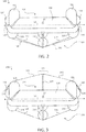
FIG. 2 illustrates a cross-sectional view of an evacuation assembly with a sheet in a negative lift configuration, in accordance with various embodiments; -
FIG. 3 illustrates a cross-sectional view of an evacuation assembly with a sheet in a canopy configuration, in accordance with various embodiments; -
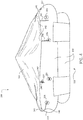
FIG. 4 illustrates a perspective view of an evacuation assembly with a sheet in a canopy configuration, in accordance with various embodiments; -
FIG. 5 illustrates a perspective view of an evacuation assembly with a sheet in a canopy configuration, in accordance with various embodiments; and -
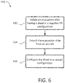
FIG. 6 is a schematic flow chart diagram of a method of using an evacuation assembly of an aircraft, in accordance with various embodiments. - The subject matter of the present disclosure is particularly pointed out and distinctly claimed in the concluding portion of the specification. A more complete understanding of the present disclosure, however, may best be obtained by referring to the detailed description and claims when considered in connection with the drawing figures, wherein like numerals denote like elements.
- The detailed description of exemplary embodiments herein makes reference to the accompanying drawings, which show exemplary embodiments by way of illustration. While these exemplary embodiments are described in sufficient detail to enable those skilled in the art to practice the disclosures, it should be understood that other embodiments may be realized and that logical changes and adaptations in design and construction may be made in accordance with this disclosure and the teachings herein. Thus, the detailed description herein is presented for purposes of illustration only and not of limitation. Throughout the present disclosure, like reference numbers denote like elements. Accordingly, elements with like element numbering may be shown in the figures but may not be necessarily be repeated herein for the sake of clarity.
- A first component that is "axially outward" of a second component means that a first component is positioned at a greater distance in either longitudinal direction away from the longitudinal center of the composite component along its longitudinal axis than the second component. A first component that is "axially inward" of a second component means that the first component is positioned closer to the longitudinal center of the composite component along its longitudinal axis than the second component.
- As used herein, "aft" refers to the direction associated with the tail (e.g., the back end) of an aircraft, or generally, to the direction of exhaust of the gas turbine. As used herein, "forward" refers to the direction associated with the nose (e.g., the front end) of an aircraft, or generally, to the direction of flight or motion.
- Referring to
FIG. 1 , anexemplary aircraft 100 is shown, in accordance with various embodiments.Aircraft 100 may comprise afuselage 102 withwings 104 fixed tofuselage 102.Emergency exit door 106 may be disposed on fuselage overwing 104 such that passengers exitingemergency exit door 106 would exit ontowing 104. Anevacuation assembly 108 may be disposed aft ofemergency exit door 106.Blowout panel 110 may coverevacuation assembly 108 when installed on theaircraft 100. In various embodiments, theevacuation assembly 108 may include and/or be housed within a packboard mounted to theaircraft 100. - The
evacuation assembly 108 may jettison theblowout panel 110 and deploy an evacuation slide, such as an inflatable evacuation slide, in response toemergency exit door 106 opening or in response to another evacuation event. A common inopportune occurrence associated with conventional evacuation slides is that when such slides are deployed in high lateral wind conditions, the wind may cause the slide to "kite" such that the toe end of the slide does not touch the ground, rendering the slide less usable. If the slide lifts off the ground above the airplane's door sill height after full extension, the slide may even block the aircraft exit and prevent safe evacuation of passengers and crew. - In the event of an emergency water landing, aircraft evacuation slides can also be used as passenger rafts. To protect passengers from the sun, rain, and/or other weather conditions while situated in the evacuation slide in raft mode, conventional evacuation assemblies have traditionally included a standalone canopy system that can be assembled, installed, and mounted to the evacuation slide after the evacuation slide is in raft mode.
- Disclosed herein, according to various embodiments, is an evacuation assembly that can be arranged in two different configurations based on whether an evacuation slide of the evacuation assembly is in slide mode or in raft mode. Said differently, the evacuation assembly disclosed herein includes a sheet that is coupled to the evacuation slide that can be utilized in a negative lift configuration to reduce or eliminate the "kiting" effect described above when the evacuation slide is in slide mode and that can also be utilized in a canopy configuration to protect passengers when the evacuation slide is in raft mode, in accordance with various embodiments.
- In various embodiments, and with reference to
FIG. 2 , theevacuation assembly 108 includes anevacuation slide 120 and asheet 140 coupled to theevacuation slide 120. Thesheet 140 is deployable in a negative lift configuration, with reference toFIG. 2 , and a canopy configuration, with reference toFIG. 3 . In the negative lift configuration (FIG. 2 ), thesheet 140 extends across at least a portion of anunderside 122 of theevacuation slide 120, according to various embodiments. As described in greater detail below, thesheet 140 disposed on theunderside 122 of theevacuation slide 120 at least partially imparts an inverted airfoil shape to the evacuation assembly, thereby creating negative lift that helps to hold the toe end of theevacuation slide 120 against the ground or against the water when theevacuation slide 120 is in slide mode. In the canopy configuration (FIG. 3 ), thesheet 140 extends over at least a portion of atop side 124 of theevacuation slide 120, according to various embodiments. Also, as described in greater detail below, with thesheet 140 disposed over thetop side 124 of theevacuation slide 120, passengers situated in theevacuation slide 120 in the raft mode are protected by thesheet 140 from sun, precipitation, and/or other weather conditions. Thesheet 140 may be made from a fabric material, a plastic material, or a composite material, among others. For example, thesheet 140 may be made from the same material as the evacuation slide 120 (e.g., nylon or nylon coated with a thermoplastic material, among others). - In various embodiments, the configuration of the
evacuation assembly 108 can be switched by a single person. For example, theevacuation slide 120 may inflate/deploy with thesheet 140 attached to theevacuation slide 120 in the negative lift configuration. After theaircraft 100 has been evacuated, theevacuation slide 120 can be detached from theaircraft 100, as described in greater detail below with reference toFIG. 6 , and theevacuation slide 120 can be converted to raft mode. In various embodiments, a single passenger can reconfigure thesheet 140 so that it no longer extends across theunderside 122 of theevacuation slide 120 but instead extends over thetop side 124 of the evacuation slide. Before describing the details pertaining to how theevacuation assembly 108 can be switched between the two configurations, it may be beneficial to first describe the features and structure of the two configurations. - In the negative lift configuration, and with reference to
FIG. 2 , thesheet 140 extends across and below at least a portion of theunderside 122 of theevacuation slide 120, according to various embodiments. Said differently, thesheet 140 may extend belowvarious support tubes 118 and/orvarious support straps 119 to impart a convex shape to theunderside 122 of theevacuation slide 120. In various embodiments, thesheet 140 contributes to the convex shape of theunderside 122 of theevacuation slide 120 such that theunderside 122 of the evacuation slide generally curves about alongitudinal axis 51 of the evacuation slide. Thelongitudinal axis 51 may extend substantially centrally along a length of theevacuation slide 120 from a head portion attached to theaircraft 100 to a toe portion that contacts the ground/water. - Accordingly, in various embodiments, a top length of a top air flow path across the
top side 124 of at least the toe portion of theevacuation slide 120 in awidth direction 52 is less than a bottom length of a bottom air flow path across the underside 122 (i.e., the sheet 140) of at least the toe portion of theevacuation slide 120 in thewidth direction 52. In other words, and according to various embodiments, the top flow path of wind across the top surface of theevacuation slide 120 in awidth direction 52, which is generally perpendicular to thelongitudinal axis 51 of theevacuation slide 120, is shorter than the bottom flow path of wind across the bottom surface. Accordingly, the velocity of the wind flowing across thetop side 124 is less than the velocity of the wind flowing across theunderside 122 of the evacuation slide, and such a velocity difference creates a pressure differential, per Bernoulli's principle, that produces a downward force on the evacuation slide. Thus, the convex shape imparted by thesheet 140 at least partially contributes to an inverted airfoil-like shape/geometry of theevacuation slide 120 that creates negative lift in windy conditions, thereby mitigating the "kiting" effect described above. - In various embodiments, the
sheet 140 extends across the entire width of theunderside 122 of theevacuation slide 120. In various embodiments, however, the sheet may not extend across an entire width of theunderside 122 of the evacuation slide, but may only extend across portions of theunderside 122 of the evacuation slide while still contributing to the convex, inverted airfoil shape. In various embodiments, thesheet 140 extends substantially along the entire longitudinal length of theevacuation slide 120. In various embodiments, the sheet may not extend along the entire longitudinal length of theevacuation slide 120, but may only be disposed along a portion (e.g., the toe portion). - In the canopy configuration, and with reference to
FIG. 3 , thesheet 140 extends across and over thetop side 124 of theevacuation slide 120, according to various embodiments. Theevacuation assembly 108 may further include one ormore supports 130 that are coupled to and extend between thetop side 124 of theevacuation slide 120 and thesheet 140 in the canopy configuration. In various embodiments, thesupport 130 may include a pole, a tube, a divider, or other suitable device/structure. Thesupport 130 may engage thesheet 140 to hold the sheet 140 a distance apart from thetop side 124 of theevacuation slide 120. In various embodiments, as described in greater detail below, thesheet 140 may be directly coupled/attached to thesupport 130. - In various embodiments, the
evacuation slide 120 includes two longitudinally extendingborder tubes 121 that extend parallel to thelongitudinal axis 51 to form opposing lateral edges of theevacuation slide 120. Thesupport 130 may be disposed in amiddle section 123 between the longitudinally extendingborder tubes 121. In various embodiments, a plurality of supports may extend along the longitudinal length of theevacuation slide 120 in themiddle section 123. For example, a first support and a second support may be disposed in themiddle section 123 but may be longitudinally spaced apart from each other. In various embodiments, thesupport 130 is a continuous structure that extends substantially along the entire longitudinal length of the evacuation slide. - In various embodiments, the
support 130 is permanently coupled to theevacuation slide 120. In various embodiments, however, thesupport 130 may be detachably coupled to theevacuation slide 120, thereby allowing a passenger/crew member to attach/detach thesupport 130 depending on which configuration (e.g., the negative lift configuration with the slide in slide mode or the canopy configuration with the slide in raft mode). - In various embodiments, and with reference to
FIGS. 2 and 3 , thesheet 140 may be detachably coupled to theevacuation slide 120 at various connection points 126. For example, thesheet 140 may be detachably tethered, tied, anchored, connected, fastened, or otherwise coupled to theevacuation slide 120 via the various connection points 126. In various embodiments, thesheet 140 may utilize the same connection points 126 regardless of the sheet's configuration. However, in various embodiments, theevacuation assembly 208 may include connection points 126 for the negative lift configuration that are different (e.g., either located in different locations along theevacuation slide 120 or that have a different connection mechanism) than the connection points 126 for the canopy configuration. In various embodiments, the sheet and/orconnection point 126 may include a ratcheting mechanism to enable a passenger/crew member to adjust the tension in thesheet 140. - In various embodiments, and with reference to
FIG. 4 , theevacuation assembly 208 includes asheet 240 extend over the top side of theevacuation slide 220 in the canopy configuration. Thesheet 240 may include afirst portion 241 that is permanently coupled to the evacuation slide 220 (via bonding, permanent adhesive, etc.) and asecond portion 242 that is detachably coupled to theevacuation slide 220. In various embodiments, thesecond portion 242 of thesheet 240 may includestraps 246 or other attachment fixtures that are engageable/connectable with corresponding anchor points 226 of theevacuation slide 220. In various embodiments, for example, thefirst portion 241 of thesheet 240 may be permanently coupled to a first lateral portion/edge 227 (e.g., a first longitudinally extending border tube) of theevacuation slide 220 and thesecond portion 242 may be detachably coupled to a second lateral portion/edge 228 (e.g., a second longitudinally extending border tube) of theevacuation slide 220. As shown inFIG. 4 , thesheet 240 may also be detachably coupled along a toe portion/edge of theevacuation slide 220 as well. - As described in greater detail below with reference to
FIG. 6 , with thefirst portion 241 of thesheet 240 permanently coupled to theevacuation slide 220 and thesecond portion 242 of thesheet 240 detachably coupled to theevacuation slide 220, a passenger/crew member can detach thesecond portion 242 from theevacuation slide 220 and reconfigure thesheet 240 to be in the desired configuration. For example, before configuring thesheet 240 in the canopy configuration depicted inFIG. 4 , thefirst portion 241 of thesheet 240 may have been folded the opposite direction at thefirst edge 227 of theevacuation slide 220 such that thesheet 240 extended across theunderside 222 of theevacuation slide 220 in response to theevacuation slide 220 being in slide mode. Thus, switching between configurations may include detaching thesecond portion 242 of thesheet 240, retracting the sheet from a first side (e.g., theunderside 222 of the evacuation slide 220), extending thesheet 240 over a second side (e.g., the top side of the evacuation slide 220), and attaching thesecond portion 242 of thesheet 240 to theevacuation slide 220. - In various embodiments, and with reference to
FIG. 5 , the sheet 340 may include two sections. Said differently, theevacuation assembly 308 may include afirst sheet 340A and asecond sheet 340B. Thefirst sheet 340A may include afirst portion 341 and asecond portion 342 and thesecond sheet 340B may include athird portion 343 and afourth portion 344. Thefirst portion 341 of thefirst sheet 340A and thethird portion 343 of thesecond sheet 340B may be permanently coupled to the evacuation slide 320 (e.g., along opposing lateral edges). In various embodiments, thesecond portion 342 of thefirst sheet 340A and thefourth portion 344 of thesecond sheet 340B may be detachably coupled together (e.g., using hook and loop type fasteners, etc.). - The
sheets evacuation assembly 308 may further includevarious straps 346 or other attachment fixtures that are engageable/connectable with corresponding anchor points 326 of theevacuation slide 320. WhileFIG. 5 depicts thesecond portion 342 and thefourth portion 344 detachably coupled together in the canopy configuration, thesecond portion 342 and thefourth portion 344 may be similarly attached together on theunderside 322 of theevacuation slide 320 in the negative lift configuration. In the canopy configuration, and according to various embodiments, thesecond portion 342 of thefirst sheet 340A and thefourth portion 344 of thesecond sheet 340B may be detachably coupled directly to the support 130 (with momentary reference toFIG. 3 ). - In various embodiments, and with reference to
FIG. 6 , amethod 690 of using an evacuation assembly of an aircraft is provided herein. Themethod 690 includes, according to various embodiments, inflating an evacuation slide having a sheet in the negative lift configuration atstep 692. That is, the evacuation slide may be inflated so as to be in slide mode to facilitate evacuation of passengers/crew. Themethod 690 further includes, according to various embodiments, detaching the evacuation slide from the aircraft atstep 694. By detaching the evacuation slide from the aircraft, the evacuation slide may be in raft mode. Themethod 690 further includes, according to various embodiments, configuring the sheet in the canopy configuration atstep 696. In various embodiments,step 696 may be performed in response to the evacuation slide being in raft mode (e.g., step 696 may be performed after step 694). - As mentioned above, configuring the sheet in the canopy configuration (step 696) may include detaching a detachable portion of the sheet from the evacuation slide, retracting the sheet form the underside of the evacuation slide, extending sheet over at least a portion of the top side of the evacuation slide, and attaching the detachable portion to the evacuation slide.
- Benefits, other advantages, and solutions to problems have been described herein with regard to specific embodiments. Furthermore, the connecting lines shown in the various figures contained herein are intended to represent exemplary functional relationships and/or physical couplings between the various elements. It should be noted that many alternative or additional functional relationships or physical connections may be present in a practical system. However, the benefits, advantages, solutions to problems, and any elements that may cause any benefit, advantage, or solution to occur or become more pronounced are not to be construed as critical, required, or essential features or elements of the disclosure.
- The scope of the disclosure is accordingly to be limited by nothing other than the appended claims, in which reference to an element in the singular is not intended to mean "one and only one" unless explicitly so stated, but rather "one or more." It is to be understood that unless specifically stated otherwise, references to "a," "an," and/or "the" may include one or more than one and that reference to an item in the singular may also include the item in the plural. All ranges and ratio limits disclosed herein may be combined.
- Moreover, where a phrase similar to "at least one of A, B, and C" is used in the claims, it is intended that the phrase be interpreted to mean that A alone may be present in an embodiment, B alone may be present in an embodiment, C alone may be present in an embodiment, or that any combination of the elements A, B and C may be present in a single embodiment; for example, A and B, A and C, B and C, or A and B and C. Different cross-hatching is used throughout the figures to denote different parts but not necessarily to denote the same or different materials.
- The steps recited in any of the method or process descriptions may be executed in any order and are not necessarily limited to the order presented. Furthermore, any reference to singular includes plural embodiments, and any reference to more than one component or step may include a singular embodiment or step. Elements and steps in the figures are illustrated for simplicity and clarity and have not necessarily been rendered according to any particular sequence. For example, steps that may be performed concurrently or in different order are illustrated in the figures to help to improve understanding of embodiments of the present disclosure.
- Any reference to attached, fixed, connected or the like may include permanent, removable, temporary, partial, full and/or any other possible attachment option. Additionally, any reference to without contact (or similar phrases) may also include reduced contact or minimal contact. Surface shading lines may be used throughout the figures to denote different parts or areas but not necessarily to denote the same or different materials. In some cases, reference coordinates may be specific to each figure.
- Systems, methods and apparatus are provided herein. In the detailed description herein, references to "one embodiment", "an embodiment", "various embodiments", etc., indicate that the embodiment described may include a particular feature, structure, or characteristic, but every embodiment may not necessarily include the particular feature, structure, or characteristic. Moreover, such phrases are not necessarily referring to the same embodiment. Further, when a particular feature, structure, or characteristic is described in connection with an embodiment, it is submitted that it is within the knowledge of one skilled in the art to affect such feature, structure, or characteristic in connection with other embodiments whether or not explicitly described. After reading the description, it will be apparent to one skilled in the relevant art(s) how to implement the disclosure in alternative embodiments.
- Furthermore, no element, component, or method step in the present disclosure is intended to be dedicated to the public regardless of whether the element, component, or method step is explicitly recited in the claims. As used herein, the terms "comprises", "comprising", or any other variation thereof, are intended to cover a non-exclusive inclusion, such that a process, method, article, or apparatus that comprises a list of elements does not include only those elements but may include other elements not expressly listed or inherent to such process, method, article, or apparatus.
Claims (15)
- An evacuation assembly (108) of an aircraft, the evacuation assembly comprising:an evacuation slide (120); anda sheet (140) coupled to the evacuation slide (120), wherein the sheet (140) is deployable in a negative lift configuration and a canopy configuration.
- The evacuation assembly of claim 1, wherein:in the negative lift configuration the sheet extends across at least a portion of an underside of the evacuation slide; andin the canopy configuration the sheet extends over at least a portion of a top side of the evacuation slide.
- The evacuation assembly of claim 2, wherein:the evacuation assembly comprises a support; andthe support is coupled to and extends between the top side of the evacuation slide and the sheet in the canopy configuration.
- The evacuation assembly of claim 3, wherein:the evacuation slide comprises a longitudinal axis and a first longitudinally extending border tube and a second longitudinally extending border tube that extend parallel to the longitudinal axis to form opposing lateral edges of the evacuation slide; andthe support is disposed in a middle section between the first longitudinally extending border tube and the second longitudinally extending border tube; and preferably wherein:the support is a first support; andthe evacuation slide comprises a second support that is longitudinally spaced apart from the first support and that is disposed in the middle section.
- The evacuation assembly of claim 2, wherein a first portion of the sheet is permanently coupled to the evacuation slide and a second portion of the sheet is detachably coupled to the evacuation slide.
- The evacuation assembly of claim 5, wherein:the evacuation slide comprises a longitudinal axis, a first longitudinally extending border tube, and a second longitudinally extending border tube;the first longitudinally extending border tube and the second longitudinally extending border tube extend parallel to the longitudinal axis to form opposing lateral edges of the evacuation slide;the first portion of the sheet is permanently coupled to the first longitudinally extending border tube; andthe second portion of the sheet is detachably coupled to the second longitudinally extending border tube; or wherein:the evacuation slide comprises a head portion and a toe portion;the first portion of the sheet is permanently coupled to at least one of the head portion and the toe portion; andthe second portion of the sheet is detachably coupled to the other of the head portion and the toe portion.
- The evacuation assembly of claim 2, wherein:the sheet is a first sheet comprising a first portion and a second portion;the evacuation assembly comprises a second sheet comprising a third portion and a fourth portion;the first portion and the third portion are permanently coupled to the evacuation slide; andthe second portion and the fourth portion are detachably coupled together.
- The evacuation assembly of claim 2, wherein:the evacuation assembly comprises a support coupled to the top side of the evacuation slide;the sheet is a first sheet comprising a first portion and a second portion;the evacuation assembly comprises a second sheet comprising a third portion and a fourth portion;the first portion and the third portion are permanently coupled to the evacuation slide;the second portion and the fourth portion are detachably coupled to the underside of the evacuation slide in the negative lift configuration; andthe second portion and the fourth portion are detachably coupled to the support in the canopy configuration.
- The evacuation assembly of claim 2, wherein in the negative lift configuration the sheet and the underside of the evacuation slide are cumulatively shaped and configured to produce negative lift in response to air flowing across the evacuation slide in a width direction, wherein the width direction is perpendicular to a longitudinal axis of the evacuation slide, and preferably wherein the evacuation slide comprises a head portion and a toe portion, wherein the longitudinal axis extends centrally along a length of the evacuation slide from the head portion to the toe portion, wherein in the negative lift configuration a top length of a top air flow path across the top side of the toe portion of the evacuation slide in the width direction is less than a bottom length of a bottom air flow path across the sheet and the underside of the toe portion of the evacuation slide in the width direction.
- An evacuation assembly of an aircraft, the evacuation assembly comprising:an evacuation slide comprising a longitudinal axis and a first longitudinally extending border tube and a second longitudinally extending border tube that extend parallel to the longitudinal axis to form opposing lateral edges of the evacuation slide;a sheet coupled to the evacuation slide, wherein:the sheet is deployable in a negative lift configuration and a canopy configuration;in the negative lift configuration the sheet extends across at least a portion of an underside of the evacuation slide; andin the canopy configuration the sheet extends over at least a portion of a top side of the evacuation slide; anda support coupled to and extending between the top side of the evacuation slide and the sheet in response to the sheet being in the canopy configuration, wherein the support is disposed in a middle section between the first longitudinally extending border tube and the second longitudinally extending border tube.
- A method of using an evacuation assembly of an aircraft, the method comprising:inflating an evacuation slide such that the evacuation slide is in slide mode, wherein in the slide mode a sheet is coupled to the evacuation slide in a negative lift configuration;detaching the evacuation slide from the aircraft such that the evacuation slide is in raft mode; andconfiguring the sheet in a canopy configuration.
- The method of claim 11, wherein configuring the sheet in the canopy configuration is performed in response to the evacuation slide being in the raft mode.
- The method of claim 11, wherein configuring the sheet in the canopy configuration is performed after detaching the evacuation slide from the aircraft; or wherein:in the negative lift configuration the sheet extends across at least a portion of an underside of the evacuation slide; andin the canopy configuration the sheet extends over at least a portion of a top side of the evacuation slide.
- The method of claim 13, wherein a first portion of the sheet is permanently coupled to the evacuation slide and a second portion of the sheet is detachably coupled to the evacuation slide, wherein configuring the sheet in the canopy configuration comprises:detaching the second portion of the sheet from the evacuation slide;retracting the sheet from the underside of the evacuation slide;extending the sheet over the portion of the top side of the evacuation slide; andafter extending the sheet over the portion of the top side of the evacuation slide, attaching the second portion of the sheet to the evacuation slide; and preferably wherein a support is coupled to the top side of the evacuation slide and is disposed in a middle section of the evacuation slide between two longitudinally extending border tubes, wherein extending the sheet over the portion of the top side of the evacuation slide comprises coupling the sheet to the support.
- The method of claim 13, wherein:a support is coupled to the top side of the evacuation slide;the sheet is a first sheet comprising a first portion and a second portion;a second sheet is coupled to the evacuation slide;the second sheet comprises a third portion and a fourth portion;the first portion and the third portion are permanently coupled to the evacuation slide;the second portion and the fourth portion are detachably coupled together in the negative lift configuration; andconfiguring the sheet in the canopy configuration comprises:detaching the second portion from the fourth portion;retracting the first sheet and the second sheet from the underside of the evacuation slide;extending the first sheet and the second sheet over the portion of the top side of the evacuation slide; andafter extending the first sheet and the second sheet over the portion of the top side of the evacuation slide, attaching the second portion and the fourth portion to the support.
Applications Claiming Priority (1)
| Application Number | Priority Date | Filing Date | Title |
|---|---|---|---|
| US15/466,473 US10457406B2 (en) | 2017-03-22 | 2017-03-22 | Dual configuration evacuation assembly |
Publications (2)
| Publication Number | Publication Date |
|---|---|
| EP3378777A1 true EP3378777A1 (en) | 2018-09-26 |
| EP3378777B1 EP3378777B1 (en) | 2022-07-13 |
Family
ID=61244439
Family Applications (1)
| Application Number | Title | Priority Date | Filing Date |
|---|---|---|---|
| EP18157337.9A Active EP3378777B1 (en) | 2017-03-22 | 2018-02-19 | Dual configuration evacuation assembly |
Country Status (2)
| Country | Link |
|---|---|
| US (1) | US10457406B2 (en) |
| EP (1) | EP3378777B1 (en) |
Cited By (1)
| Publication number | Priority date | Publication date | Assignee | Title |
|---|---|---|---|---|
| CN109515647A (en) * | 2018-11-29 | 2019-03-26 | 浙江海洋大学 | A kind of Multifunctional life-ring |
Families Citing this family (1)
| Publication number | Priority date | Publication date | Assignee | Title |
|---|---|---|---|---|
| US10647437B2 (en) | 2017-09-25 | 2020-05-12 | Goodrich Corporation | Continuously tensioned truss strap |
Citations (2)
| Publication number | Priority date | Publication date | Assignee | Title |
|---|---|---|---|---|
| US3833088A (en) * | 1972-10-18 | 1974-09-03 | Sargent Industries | Slide-raft for emergency aircraft evacuation |
| EP0034371A2 (en) * | 1980-02-19 | 1981-08-26 | The B.F. GOODRICH Company | Escape slide and protective shield |
Family Cites Families (8)
| Publication number | Priority date | Publication date | Assignee | Title |
|---|---|---|---|---|
| US2804633A (en) | 1954-07-15 | 1957-09-03 | Garrett Corp | Inflatable life raft comprising improved canopy and supporting means therefor |
| US3827094A (en) * | 1973-06-25 | 1974-08-06 | Goodrich Co B F | Inflatable life raft escape slide |
| US3860984A (en) | 1973-06-25 | 1975-01-21 | Goodrich Co B F | Inflatable life raft escape slide |
| US4519782A (en) * | 1980-02-19 | 1985-05-28 | The B. F. Goodrich Company | Escape slide and life raft |
| DE19645205A1 (en) | 1996-11-02 | 1998-05-07 | Scheibert Dt Schlauchbootfab | Additional device for inflatable life rafts |
| US5733158A (en) | 1996-11-12 | 1998-03-31 | Dunlop-Beaufort Canada Ltd. | Inflatable reversible life raft |
| US6536715B1 (en) * | 2001-06-15 | 2003-03-25 | Air Cruisers Company | Inflatable evacuation slide with arch support |
| US9162735B2 (en) | 2008-08-28 | 2015-10-20 | Michael Grainger | Inflatable evacuation slide |
-
2017
- 2017-03-22 US US15/466,473 patent/US10457406B2/en active Active
-
2018
- 2018-02-19 EP EP18157337.9A patent/EP3378777B1/en active Active
Patent Citations (2)
| Publication number | Priority date | Publication date | Assignee | Title |
|---|---|---|---|---|
| US3833088A (en) * | 1972-10-18 | 1974-09-03 | Sargent Industries | Slide-raft for emergency aircraft evacuation |
| EP0034371A2 (en) * | 1980-02-19 | 1981-08-26 | The B.F. GOODRICH Company | Escape slide and protective shield |
Cited By (1)
| Publication number | Priority date | Publication date | Assignee | Title |
|---|---|---|---|---|
| CN109515647A (en) * | 2018-11-29 | 2019-03-26 | 浙江海洋大学 | A kind of Multifunctional life-ring |
Also Published As
| Publication number | Publication date |
|---|---|
| US10457406B2 (en) | 2019-10-29 |
| EP3378777B1 (en) | 2022-07-13 |
| US20180273190A1 (en) | 2018-09-27 |
Similar Documents
| Publication | Publication Date | Title |
|---|---|---|
| US10752368B2 (en) | Asymmetric yoke | |
| CA2177155C (en) | Deployable wing | |
| US3987984A (en) | Semi-rigid aircraft wing | |
| US5362017A (en) | Parawing | |
| US5201482A (en) | RAM air inflatable gliding wing | |
| US7093803B2 (en) | Apparatus and method for aerodynamic wing | |
| US10793280B2 (en) | Evacuation system with wind lift deterrent | |
| US20190112059A1 (en) | Evacuation slide with aspirator retention strap | |
| EP3241752B1 (en) | Systems and methods for retaining removable panel when deploying evacuation system | |
| EP3378776B1 (en) | Dual configuration wind curtain for evacuation assembly | |
| EP3378777B1 (en) | Dual configuration evacuation assembly | |
| EP2857673A1 (en) | Systems, methods, and apparatus for an emergency power generator | |
| US10464682B2 (en) | Negative lift evacuation slide | |
| US3289976A (en) | Aircraft | |
| WO2004087499A2 (en) | Airship | |
| US4637576A (en) | Parachute with leading-edge slats | |
| US4776538A (en) | Parachute with leading-edge slats | |
| US6769649B2 (en) | Ram air parachute canopy with improved nose structure | |
| US10640220B2 (en) | Anti-kiting device | |
| US6929221B2 (en) | Ram air parachute with tensioned top skin | |
| US20030209634A1 (en) | Ram air parachute canopy with trapezoidal cells | |
| IL152515A (en) | Parachute slider with nozzles | |
| GB2630733A (en) | Parafoil launch system | |
| WO2003053779A2 (en) | Ram air parachute with improved canopy design |
Legal Events
| Date | Code | Title | Description |
|---|---|---|---|
| PUAI | Public reference made under article 153(3) epc to a published international application that has entered the european phase |
Free format text: ORIGINAL CODE: 0009012 |
|
| STAA | Information on the status of an ep patent application or granted ep patent |
Free format text: STATUS: THE APPLICATION HAS BEEN PUBLISHED |
|
| AK | Designated contracting states |
Kind code of ref document: A1 Designated state(s): AL AT BE BG CH CY CZ DE DK EE ES FI FR GB GR HR HU IE IS IT LI LT LU LV MC MK MT NL NO PL PT RO RS SE SI SK SM TR |
|
| AX | Request for extension of the european patent |
Extension state: BA ME |
|
| STAA | Information on the status of an ep patent application or granted ep patent |
Free format text: STATUS: REQUEST FOR EXAMINATION WAS MADE |
|
| 17P | Request for examination filed |
Effective date: 20190320 |
|
| RBV | Designated contracting states (corrected) |
Designated state(s): AL AT BE BG CH CY CZ DE DK EE ES FI FR GB GR HR HU IE IS IT LI LT LU LV MC MK MT NL NO PL PT RO RS SE SI SK SM TR |
|
| STAA | Information on the status of an ep patent application or granted ep patent |
Free format text: STATUS: EXAMINATION IS IN PROGRESS |
|
| 17Q | First examination report despatched |
Effective date: 20190812 |
|
| GRAP | Despatch of communication of intention to grant a patent |
Free format text: ORIGINAL CODE: EPIDOSNIGR1 |
|
| STAA | Information on the status of an ep patent application or granted ep patent |
Free format text: STATUS: GRANT OF PATENT IS INTENDED |
|
| INTG | Intention to grant announced |
Effective date: 20220217 |
|
| RIN1 | Information on inventor provided before grant (corrected) |
Inventor name: SCHMIDT, RYAN Inventor name: HAYNES, TIMOTHY C. |
|
| GRAS | Grant fee paid |
Free format text: ORIGINAL CODE: EPIDOSNIGR3 |
|
| GRAA | (expected) grant |
Free format text: ORIGINAL CODE: 0009210 |
|
| STAA | Information on the status of an ep patent application or granted ep patent |
Free format text: STATUS: THE PATENT HAS BEEN GRANTED |
|
| AK | Designated contracting states |
Kind code of ref document: B1 Designated state(s): AL AT BE BG CH CY CZ DE DK EE ES FI FR GB GR HR HU IE IS IT LI LT LU LV MC MK MT NL NO PL PT RO RS SE SI SK SM TR |
|
| REG | Reference to a national code |
Ref country code: CH Ref legal event code: EP |
|
| REG | Reference to a national code |
Ref country code: DE Ref legal event code: R096 Ref document number: 602018037807 Country of ref document: DE |
|
| REG | Reference to a national code |
Ref country code: AT Ref legal event code: REF Ref document number: 1504167 Country of ref document: AT Kind code of ref document: T Effective date: 20220815 |
|
| REG | Reference to a national code |
Ref country code: IE Ref legal event code: FG4D |
|
| REG | Reference to a national code |
Ref country code: LT Ref legal event code: MG9D |
|
| REG | Reference to a national code |
Ref country code: NL Ref legal event code: MP Effective date: 20220713 |
|
| PG25 | Lapsed in a contracting state [announced via postgrant information from national office to epo] |
Ref country code: SE Free format text: LAPSE BECAUSE OF FAILURE TO SUBMIT A TRANSLATION OF THE DESCRIPTION OR TO PAY THE FEE WITHIN THE PRESCRIBED TIME-LIMIT Effective date: 20220713 Ref country code: RS Free format text: LAPSE BECAUSE OF FAILURE TO SUBMIT A TRANSLATION OF THE DESCRIPTION OR TO PAY THE FEE WITHIN THE PRESCRIBED TIME-LIMIT Effective date: 20220713 Ref country code: PT Free format text: LAPSE BECAUSE OF FAILURE TO SUBMIT A TRANSLATION OF THE DESCRIPTION OR TO PAY THE FEE WITHIN THE PRESCRIBED TIME-LIMIT Effective date: 20221114 Ref country code: NO Free format text: LAPSE BECAUSE OF FAILURE TO SUBMIT A TRANSLATION OF THE DESCRIPTION OR TO PAY THE FEE WITHIN THE PRESCRIBED TIME-LIMIT Effective date: 20221013 Ref country code: NL Free format text: LAPSE BECAUSE OF FAILURE TO SUBMIT A TRANSLATION OF THE DESCRIPTION OR TO PAY THE FEE WITHIN THE PRESCRIBED TIME-LIMIT Effective date: 20220713 Ref country code: LV Free format text: LAPSE BECAUSE OF FAILURE TO SUBMIT A TRANSLATION OF THE DESCRIPTION OR TO PAY THE FEE WITHIN THE PRESCRIBED TIME-LIMIT Effective date: 20220713 Ref country code: LT Free format text: LAPSE BECAUSE OF FAILURE TO SUBMIT A TRANSLATION OF THE DESCRIPTION OR TO PAY THE FEE WITHIN THE PRESCRIBED TIME-LIMIT Effective date: 20220713 Ref country code: FI Free format text: LAPSE BECAUSE OF FAILURE TO SUBMIT A TRANSLATION OF THE DESCRIPTION OR TO PAY THE FEE WITHIN THE PRESCRIBED TIME-LIMIT Effective date: 20220713 Ref country code: ES Free format text: LAPSE BECAUSE OF FAILURE TO SUBMIT A TRANSLATION OF THE DESCRIPTION OR TO PAY THE FEE WITHIN THE PRESCRIBED TIME-LIMIT Effective date: 20220713 |
|
| REG | Reference to a national code |
Ref country code: AT Ref legal event code: MK05 Ref document number: 1504167 Country of ref document: AT Kind code of ref document: T Effective date: 20220713 |
|
| PG25 | Lapsed in a contracting state [announced via postgrant information from national office to epo] |
Ref country code: PL Free format text: LAPSE BECAUSE OF FAILURE TO SUBMIT A TRANSLATION OF THE DESCRIPTION OR TO PAY THE FEE WITHIN THE PRESCRIBED TIME-LIMIT Effective date: 20220713 Ref country code: IS Free format text: LAPSE BECAUSE OF FAILURE TO SUBMIT A TRANSLATION OF THE DESCRIPTION OR TO PAY THE FEE WITHIN THE PRESCRIBED TIME-LIMIT Effective date: 20221113 Ref country code: HR Free format text: LAPSE BECAUSE OF FAILURE TO SUBMIT A TRANSLATION OF THE DESCRIPTION OR TO PAY THE FEE WITHIN THE PRESCRIBED TIME-LIMIT Effective date: 20220713 Ref country code: GR Free format text: LAPSE BECAUSE OF FAILURE TO SUBMIT A TRANSLATION OF THE DESCRIPTION OR TO PAY THE FEE WITHIN THE PRESCRIBED TIME-LIMIT Effective date: 20221014 |
|
| REG | Reference to a national code |
Ref country code: DE Ref legal event code: R097 Ref document number: 602018037807 Country of ref document: DE |
|
| PG25 | Lapsed in a contracting state [announced via postgrant information from national office to epo] |
Ref country code: SM Free format text: LAPSE BECAUSE OF FAILURE TO SUBMIT A TRANSLATION OF THE DESCRIPTION OR TO PAY THE FEE WITHIN THE PRESCRIBED TIME-LIMIT Effective date: 20220713 Ref country code: RO Free format text: LAPSE BECAUSE OF FAILURE TO SUBMIT A TRANSLATION OF THE DESCRIPTION OR TO PAY THE FEE WITHIN THE PRESCRIBED TIME-LIMIT Effective date: 20220713 Ref country code: DK Free format text: LAPSE BECAUSE OF FAILURE TO SUBMIT A TRANSLATION OF THE DESCRIPTION OR TO PAY THE FEE WITHIN THE PRESCRIBED TIME-LIMIT Effective date: 20220713 Ref country code: CZ Free format text: LAPSE BECAUSE OF FAILURE TO SUBMIT A TRANSLATION OF THE DESCRIPTION OR TO PAY THE FEE WITHIN THE PRESCRIBED TIME-LIMIT Effective date: 20220713 Ref country code: AT Free format text: LAPSE BECAUSE OF FAILURE TO SUBMIT A TRANSLATION OF THE DESCRIPTION OR TO PAY THE FEE WITHIN THE PRESCRIBED TIME-LIMIT Effective date: 20220713 |
|
| PLBE | No opposition filed within time limit |
Free format text: ORIGINAL CODE: 0009261 |
|
| STAA | Information on the status of an ep patent application or granted ep patent |
Free format text: STATUS: NO OPPOSITION FILED WITHIN TIME LIMIT |
|
| PG25 | Lapsed in a contracting state [announced via postgrant information from national office to epo] |
Ref country code: SK Free format text: LAPSE BECAUSE OF FAILURE TO SUBMIT A TRANSLATION OF THE DESCRIPTION OR TO PAY THE FEE WITHIN THE PRESCRIBED TIME-LIMIT Effective date: 20220713 Ref country code: EE Free format text: LAPSE BECAUSE OF FAILURE TO SUBMIT A TRANSLATION OF THE DESCRIPTION OR TO PAY THE FEE WITHIN THE PRESCRIBED TIME-LIMIT Effective date: 20220713 |
|
| 26N | No opposition filed |
Effective date: 20230414 |
|
| P01 | Opt-out of the competence of the unified patent court (upc) registered |
Effective date: 20230522 |
|
| PG25 | Lapsed in a contracting state [announced via postgrant information from national office to epo] |
Ref country code: AL Free format text: LAPSE BECAUSE OF FAILURE TO SUBMIT A TRANSLATION OF THE DESCRIPTION OR TO PAY THE FEE WITHIN THE PRESCRIBED TIME-LIMIT Effective date: 20220713 |
|
| PG25 | Lapsed in a contracting state [announced via postgrant information from national office to epo] |
Ref country code: SI Free format text: LAPSE BECAUSE OF FAILURE TO SUBMIT A TRANSLATION OF THE DESCRIPTION OR TO PAY THE FEE WITHIN THE PRESCRIBED TIME-LIMIT Effective date: 20220713 |
|
| PG25 | Lapsed in a contracting state [announced via postgrant information from national office to epo] |
Ref country code: MC Free format text: LAPSE BECAUSE OF FAILURE TO SUBMIT A TRANSLATION OF THE DESCRIPTION OR TO PAY THE FEE WITHIN THE PRESCRIBED TIME-LIMIT Effective date: 20220713 |
|
| REG | Reference to a national code |
Ref country code: CH Ref legal event code: PL |
|
| REG | Reference to a national code |
Ref country code: BE Ref legal event code: MM Effective date: 20230228 |
|
| PG25 | Lapsed in a contracting state [announced via postgrant information from national office to epo] |
Ref country code: LU Free format text: LAPSE BECAUSE OF NON-PAYMENT OF DUE FEES Effective date: 20230219 Ref country code: LI Free format text: LAPSE BECAUSE OF NON-PAYMENT OF DUE FEES Effective date: 20230228 Ref country code: CH Free format text: LAPSE BECAUSE OF NON-PAYMENT OF DUE FEES Effective date: 20230228 |
|
| REG | Reference to a national code |
Ref country code: IE Ref legal event code: MM4A |
|
| PG25 | Lapsed in a contracting state [announced via postgrant information from national office to epo] |
Ref country code: IT Free format text: LAPSE BECAUSE OF FAILURE TO SUBMIT A TRANSLATION OF THE DESCRIPTION OR TO PAY THE FEE WITHIN THE PRESCRIBED TIME-LIMIT Effective date: 20220713 Ref country code: IE Free format text: LAPSE BECAUSE OF NON-PAYMENT OF DUE FEES Effective date: 20230219 |
|
| PG25 | Lapsed in a contracting state [announced via postgrant information from national office to epo] |
Ref country code: BE Free format text: LAPSE BECAUSE OF NON-PAYMENT OF DUE FEES Effective date: 20230228 |
|
| PG25 | Lapsed in a contracting state [announced via postgrant information from national office to epo] |
Ref country code: BG Free format text: LAPSE BECAUSE OF FAILURE TO SUBMIT A TRANSLATION OF THE DESCRIPTION OR TO PAY THE FEE WITHIN THE PRESCRIBED TIME-LIMIT Effective date: 20220713 |
|
| PG25 | Lapsed in a contracting state [announced via postgrant information from national office to epo] |
Ref country code: BG Free format text: LAPSE BECAUSE OF FAILURE TO SUBMIT A TRANSLATION OF THE DESCRIPTION OR TO PAY THE FEE WITHIN THE PRESCRIBED TIME-LIMIT Effective date: 20220713 |
|
| PG25 | Lapsed in a contracting state [announced via postgrant information from national office to epo] |
Ref country code: CY Free format text: LAPSE BECAUSE OF FAILURE TO SUBMIT A TRANSLATION OF THE DESCRIPTION OR TO PAY THE FEE WITHIN THE PRESCRIBED TIME-LIMIT; INVALID AB INITIO Effective date: 20180219 |
|
| PG25 | Lapsed in a contracting state [announced via postgrant information from national office to epo] |
Ref country code: HU Free format text: LAPSE BECAUSE OF FAILURE TO SUBMIT A TRANSLATION OF THE DESCRIPTION OR TO PAY THE FEE WITHIN THE PRESCRIBED TIME-LIMIT; INVALID AB INITIO Effective date: 20180219 |
|
| PG25 | Lapsed in a contracting state [announced via postgrant information from national office to epo] |
Ref country code: TR Free format text: LAPSE BECAUSE OF FAILURE TO SUBMIT A TRANSLATION OF THE DESCRIPTION OR TO PAY THE FEE WITHIN THE PRESCRIBED TIME-LIMIT Effective date: 20220713 |
|
| PGFP | Annual fee paid to national office [announced via postgrant information from national office to epo] |
Ref country code: GB Payment date: 20260121 Year of fee payment: 9 |
|
| PGFP | Annual fee paid to national office [announced via postgrant information from national office to epo] |
Ref country code: DE Payment date: 20260121 Year of fee payment: 9 |
|
| PGFP | Annual fee paid to national office [announced via postgrant information from national office to epo] |
Ref country code: FR Payment date: 20260121 Year of fee payment: 9 |