EP3378763A1 - Aircraft hydraulic systems having shared components - Google Patents
Aircraft hydraulic systems having shared components Download PDFInfo
- Publication number
- EP3378763A1 EP3378763A1 EP18155552.5A EP18155552A EP3378763A1 EP 3378763 A1 EP3378763 A1 EP 3378763A1 EP 18155552 A EP18155552 A EP 18155552A EP 3378763 A1 EP3378763 A1 EP 3378763A1
- Authority
- EP
- European Patent Office
- Prior art keywords
- hydraulic
- subsystem
- shared
- pump
- powered components
- Prior art date
- Legal status (The legal status is an assumption and is not a legal conclusion. Google has not performed a legal analysis and makes no representation as to the accuracy of the status listed.)
- Granted
Links
Images

Classifications
-
- B—PERFORMING OPERATIONS; TRANSPORTING
- B64—AIRCRAFT; AVIATION; COSMONAUTICS
- B64C—AEROPLANES; HELICOPTERS
- B64C13/00—Control systems or transmitting systems for actuating flying-control surfaces, lift-increasing flaps, air brakes, or spoilers
- B64C13/24—Transmitting means
- B64C13/38—Transmitting means with power amplification
- B64C13/40—Transmitting means with power amplification using fluid pressure
-
- F—MECHANICAL ENGINEERING; LIGHTING; HEATING; WEAPONS; BLASTING
- F15—FLUID-PRESSURE ACTUATORS; HYDRAULICS OR PNEUMATICS IN GENERAL
- F15B—SYSTEMS ACTING BY MEANS OF FLUIDS IN GENERAL; FLUID-PRESSURE ACTUATORS, e.g. SERVOMOTORS; DETAILS OF FLUID-PRESSURE SYSTEMS, NOT OTHERWISE PROVIDED FOR
- F15B11/00—Servomotor systems without provision for follow-up action ; Circuits therefor
- F15B11/16—Servomotor systems without provision for follow-up action ; Circuits therefor with two or more servomotors
- F15B11/17—Servomotor systems without provision for follow-up action ; Circuits therefor with two or more servomotors using two or more pumps
-
- B—PERFORMING OPERATIONS; TRANSPORTING
- B64—AIRCRAFT; AVIATION; COSMONAUTICS
- B64C—AEROPLANES; HELICOPTERS
- B64C13/00—Control systems or transmitting systems for actuating flying-control surfaces, lift-increasing flaps, air brakes, or spoilers
- B64C13/24—Transmitting means
- B64C13/26—Transmitting means without power amplification or where power amplification is irrelevant
- B64C13/36—Transmitting means without power amplification or where power amplification is irrelevant fluid
-
- B—PERFORMING OPERATIONS; TRANSPORTING
- B64—AIRCRAFT; AVIATION; COSMONAUTICS
- B64C—AEROPLANES; HELICOPTERS
- B64C13/00—Control systems or transmitting systems for actuating flying-control surfaces, lift-increasing flaps, air brakes, or spoilers
- B64C13/24—Transmitting means
- B64C13/38—Transmitting means with power amplification
- B64C13/40—Transmitting means with power amplification using fluid pressure
- B64C13/42—Transmitting means with power amplification using fluid pressure having duplication or stand-by provisions
-
- B—PERFORMING OPERATIONS; TRANSPORTING
- B64—AIRCRAFT; AVIATION; COSMONAUTICS
- B64C—AEROPLANES; HELICOPTERS
- B64C27/00—Rotorcraft; Rotors peculiar thereto
- B64C27/22—Compound rotorcraft, i.e. aircraft using in flight the features of both aeroplane and rotorcraft
- B64C27/28—Compound rotorcraft, i.e. aircraft using in flight the features of both aeroplane and rotorcraft with forward-propulsion propellers pivotable to act as lifting rotors
-
- B—PERFORMING OPERATIONS; TRANSPORTING
- B64—AIRCRAFT; AVIATION; COSMONAUTICS
- B64C—AEROPLANES; HELICOPTERS
- B64C29/00—Aircraft capable of landing or taking-off vertically, e.g. vertical take-off and landing [VTOL] aircraft
- B64C29/0008—Aircraft capable of landing or taking-off vertically, e.g. vertical take-off and landing [VTOL] aircraft having its flight directional axis horizontal when grounded
- B64C29/0016—Aircraft capable of landing or taking-off vertically, e.g. vertical take-off and landing [VTOL] aircraft having its flight directional axis horizontal when grounded the lift during taking-off being created by free or ducted propellers or by blowers
- B64C29/0033—Aircraft capable of landing or taking-off vertically, e.g. vertical take-off and landing [VTOL] aircraft having its flight directional axis horizontal when grounded the lift during taking-off being created by free or ducted propellers or by blowers the propellers being tiltable relative to the fuselage
-
- B—PERFORMING OPERATIONS; TRANSPORTING
- B64—AIRCRAFT; AVIATION; COSMONAUTICS
- B64D—EQUIPMENT FOR FITTING IN OR TO AIRCRAFT; FLIGHT SUITS; PARACHUTES; ARRANGEMENT OR MOUNTING OF POWER PLANTS OR PROPULSION TRANSMISSIONS IN AIRCRAFT
- B64D29/00—Power-plant nacelles, fairings or cowlings
- B64D29/02—Power-plant nacelles, fairings or cowlings associated with wings
-
- B—PERFORMING OPERATIONS; TRANSPORTING
- B64—AIRCRAFT; AVIATION; COSMONAUTICS
- B64D—EQUIPMENT FOR FITTING IN OR TO AIRCRAFT; FLIGHT SUITS; PARACHUTES; ARRANGEMENT OR MOUNTING OF POWER PLANTS OR PROPULSION TRANSMISSIONS IN AIRCRAFT
- B64D41/00—Power installations for auxiliary purposes
-
- F—MECHANICAL ENGINEERING; LIGHTING; HEATING; WEAPONS; BLASTING
- F15—FLUID-PRESSURE ACTUATORS; HYDRAULICS OR PNEUMATICS IN GENERAL
- F15B—SYSTEMS ACTING BY MEANS OF FLUIDS IN GENERAL; FLUID-PRESSURE ACTUATORS, e.g. SERVOMOTORS; DETAILS OF FLUID-PRESSURE SYSTEMS, NOT OTHERWISE PROVIDED FOR
- F15B1/00—Installations or systems with accumulators; Supply reservoir or sump assemblies
- F15B1/26—Supply reservoir or sump assemblies
-
- F—MECHANICAL ENGINEERING; LIGHTING; HEATING; WEAPONS; BLASTING
- F15—FLUID-PRESSURE ACTUATORS; HYDRAULICS OR PNEUMATICS IN GENERAL
- F15B—SYSTEMS ACTING BY MEANS OF FLUIDS IN GENERAL; FLUID-PRESSURE ACTUATORS, e.g. SERVOMOTORS; DETAILS OF FLUID-PRESSURE SYSTEMS, NOT OTHERWISE PROVIDED FOR
- F15B18/00—Parallel arrangements of independent servomotor systems
-
- F—MECHANICAL ENGINEERING; LIGHTING; HEATING; WEAPONS; BLASTING
- F15—FLUID-PRESSURE ACTUATORS; HYDRAULICS OR PNEUMATICS IN GENERAL
- F15B—SYSTEMS ACTING BY MEANS OF FLUIDS IN GENERAL; FLUID-PRESSURE ACTUATORS, e.g. SERVOMOTORS; DETAILS OF FLUID-PRESSURE SYSTEMS, NOT OTHERWISE PROVIDED FOR
- F15B2211/00—Circuits for servomotor systems
- F15B2211/20—Fluid pressure source, e.g. accumulator or variable axial piston pump
- F15B2211/205—Systems with pumps
- F15B2211/20507—Type of prime mover
-
- F—MECHANICAL ENGINEERING; LIGHTING; HEATING; WEAPONS; BLASTING
- F15—FLUID-PRESSURE ACTUATORS; HYDRAULICS OR PNEUMATICS IN GENERAL
- F15B—SYSTEMS ACTING BY MEANS OF FLUIDS IN GENERAL; FLUID-PRESSURE ACTUATORS, e.g. SERVOMOTORS; DETAILS OF FLUID-PRESSURE SYSTEMS, NOT OTHERWISE PROVIDED FOR
- F15B2211/00—Circuits for servomotor systems
- F15B2211/20—Fluid pressure source, e.g. accumulator or variable axial piston pump
- F15B2211/205—Systems with pumps
- F15B2211/20507—Type of prime mover
- F15B2211/20523—Internal combustion engine
-
- F—MECHANICAL ENGINEERING; LIGHTING; HEATING; WEAPONS; BLASTING
- F15—FLUID-PRESSURE ACTUATORS; HYDRAULICS OR PNEUMATICS IN GENERAL
- F15B—SYSTEMS ACTING BY MEANS OF FLUIDS IN GENERAL; FLUID-PRESSURE ACTUATORS, e.g. SERVOMOTORS; DETAILS OF FLUID-PRESSURE SYSTEMS, NOT OTHERWISE PROVIDED FOR
- F15B2211/00—Circuits for servomotor systems
- F15B2211/20—Fluid pressure source, e.g. accumulator or variable axial piston pump
- F15B2211/205—Systems with pumps
- F15B2211/20576—Systems with pumps with multiple pumps
-
- F—MECHANICAL ENGINEERING; LIGHTING; HEATING; WEAPONS; BLASTING
- F15—FLUID-PRESSURE ACTUATORS; HYDRAULICS OR PNEUMATICS IN GENERAL
- F15B—SYSTEMS ACTING BY MEANS OF FLUIDS IN GENERAL; FLUID-PRESSURE ACTUATORS, e.g. SERVOMOTORS; DETAILS OF FLUID-PRESSURE SYSTEMS, NOT OTHERWISE PROVIDED FOR
- F15B2211/00—Circuits for servomotor systems
- F15B2211/70—Output members, e.g. hydraulic motors or cylinders or control therefor
- F15B2211/71—Multiple output members, e.g. multiple hydraulic motors or cylinders
- F15B2211/7142—Multiple output members, e.g. multiple hydraulic motors or cylinders the output members being arranged in multiple groups
-
- Y—GENERAL TAGGING OF NEW TECHNOLOGICAL DEVELOPMENTS; GENERAL TAGGING OF CROSS-SECTIONAL TECHNOLOGIES SPANNING OVER SEVERAL SECTIONS OF THE IPC; TECHNICAL SUBJECTS COVERED BY FORMER USPC CROSS-REFERENCE ART COLLECTIONS [XRACs] AND DIGESTS
- Y02—TECHNOLOGIES OR APPLICATIONS FOR MITIGATION OR ADAPTATION AGAINST CLIMATE CHANGE
- Y02T—CLIMATE CHANGE MITIGATION TECHNOLOGIES RELATED TO TRANSPORTATION
- Y02T50/00—Aeronautics or air transport
- Y02T50/40—Weight reduction
Definitions
- the present disclosure relates, in general, to hydraulic systems for an aircraft and, in particular, to aircraft hydraulic systems with two or more hydraulic subsystems having shared components.
- Hydraulic systems are commonly employed on aircraft to perform a variety of different operations. For example, hydraulic systems may be used to start one or more engines, move control surfaces and apply wheel brakes, among other things. Aircraft sometimes use multiple independent hydraulic circuits that employ altogether different componentry, even in cases in which independent componentry is redundant or unnecessary. The redundant use of hydraulic components increases the weight of the aircraft, adds to aircraft cost and occupies valuable space within the aircraft. Accordingly, a need has arisen for a hydraulic system having two or more hydraulic subsystems that share one or more components, thereby mitigating the aforementioned problems, among others, found in current hydraulic systems.
- the present disclosure is directed to a hydraulic system for an aircraft having an engine and an auxiliary power unit.
- the hydraulic system includes a first hydraulic subsystem including a first hydraulic pump and a first set of hydraulic-powered components in fluid communication with the first hydraulic pump.
- the first hydraulic pump is powered by the engine to pump shared hydraulic fluid to the first set of hydraulic-powered components.
- the hydraulic system includes a second hydraulic subsystem including a second hydraulic pump and a second set of hydraulic-powered components in fluid communication with the second hydraulic pump.
- the second hydraulic pump is powered by the auxiliary power unit to pump the shared hydraulic fluid to the second set of hydraulic-powered components.
- the hydraulic system also includes a shared return line subsystem in fluid communication with the first and second hydraulic subsystems to return the shared hydraulic fluid from the first and second sets of hydraulic-powered components to the first and second hydraulic pumps.
- the hydraulic system may include a shared reservoir in fluid communication with the shared return line subsystem, the shared reservoir adapted to store the shared hydraulic fluid usable by the first and second hydraulic subsystems.
- the shared return line subsystem may be adapted to return the shared hydraulic fluid to the first hydraulic pump, the second hydraulic pump and the shared reservoir.
- the shared return line subsystem may return the shared hydraulic fluid to the first hydraulic pump via the shared reservoir.
- the first hydraulic subsystem may include a first set of pressure lines providing fluid communication between the first hydraulic pump and the first set of hydraulic-powered components
- the second hydraulic subsystem may include a second set of pressure lines providing fluid communication between the second hydraulic pump and the second set of hydraulic-powered components.
- one of the first or second hydraulic subsystems may be a flight essential hydraulic subsystem and the other of the first or second hydraulic subsystems may be a non-flight essential hydraulic subsystem.
- the first hydraulic subsystem may be the flight essential hydraulic subsystem and the second hydraulic subsystem may be the non-flight essential hydraulic subsystem.
- the flight essential hydraulic subsystem may include a flight control hydraulic subsystem and the non-flight essential hydraulic subsystem may include a ground checkout and engine starting hydraulic subsystem.
- the first hydraulic subsystem may include a flight control hydraulic subsystem.
- the first set of hydraulic-powered components of the flight control hydraulic subsystem may include at least one flight control actuator, such as a wing flight control actuator, a tail section flight control actuator or a nacelle flight control actuator, each adapted to move a flight control surface.
- the second hydraulic subsystem may include a ground checkout and engine starting hydraulic subsystem.
- the second set of hydraulic-powered components of the ground checkout and engine starting hydraulic subsystem may include at least one ground operation component, such as an engine start hydraulic motor.
- the ground checkout and engine starting hydraulic subsystem may include a ground operations isolation valve downstream of the second hydraulic pump, the ground operations isolation valve adapted to be selectively opened to allow the second hydraulic pump to provide the shared hydraulic fluid to the first set of hydraulic-powered components during ground operations.
- the first hydraulic subsystem may be in fluid communication with the second hydraulic subsystem via the shared return line subsystem.
- the hydraulic system may include at least one switching valve downstream of the first and second hydraulic pumps, the at least one switching valve movable into a plurality of positions including a first position and a second position.
- the at least one switching valve may allow the first hydraulic pump to provide the shared hydraulic fluid to the second set of hydraulic-powered components, and in the second position the at least one switching valve may allow the second hydraulic pump to provide the shared hydraulic fluid to the first set of hydraulic-powered components.
- at least one of the first or second hydraulic subsystems may have an operating pressure of between about 2500 and 3500 pounds per square inch.
- the present disclosure is directed to an aircraft including one or more engines, an auxiliary power unit and a hydraulic system.
- the hydraulic system includes a first hydraulic subsystem including a first hydraulic pump and a first set of hydraulic-powered components in fluid communication with the first hydraulic pump.
- the first hydraulic pump is powered by the one or more engines to pump shared hydraulic fluid to the first set of hydraulic-powered components.
- the hydraulic system includes a second hydraulic subsystem including a second hydraulic pump and a second set of hydraulic-powered components in fluid communication with the second hydraulic pump.
- the second hydraulic pump is powered by the auxiliary power unit to pump the shared hydraulic fluid to the second set of hydraulic-powered components.
- the hydraulic system also includes a shared return line subsystem in fluid communication with the first and second hydraulic subsystems to return the shared hydraulic fluid from the first and second sets of hydraulic-powered components to the first and second hydraulic pumps.
- the aircraft may be a tiltrotor aircraft.
- the tiltrotor aircraft may include a wing having first and second ends and first and second nacelles coupled to the first and second ends of the wing, respectively, the first and second nacelles each having one or more flight control surfaces.
- the first set of hydraulic-powered components of the first hydraulic subsystem may include a first nacelle flight control actuator adapted to control the one or more flight control surfaces of the first nacelle and a second nacelle flight control actuator adapted to control the one or more flight control surfaces of the second nacelle.
- the tiltrotor aircraft may include a wing having first and second ends and first and second nacelles coupled to the first and second ends of the wing, respectively, the first and second nacelles each having an engine.
- the second set of hydraulic-powered components of the second hydraulic subsystem may include a first engine start hydraulic motor adapted to start the engine of the first nacelle and a second engine start hydraulic motor adapted to start the engine of the second nacelle.
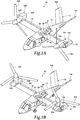
- Tiltrotor aircraft 10 includes a fuselage 12 and a tail section 14 including rotatably mounted tail members 14a, 14b having control surfaces operable for horizontal and/or vertical stabilization during forward flight.
- a wing 16 is supported by fuselage 12.
- propulsion assemblies 18a, 18b Located at outboard ends of wing 16 are propulsion assemblies 18a, 18b.
- Propulsion assembly 18a includes a fixed nacelle 20a that houses an engine 22 and a transmission.
- propulsion assembly 18a includes a pylon assembly 24a that is rotatable relative to fixed nacelle 20a between a generally horizontal orientation, as best seen in figure 1A , and a generally vertical orientation, as best seen in figure IB.
- Propulsion assembly 18a also includes a proprotor assembly 26a that is rotatable relative to pylon assembly 24a responsive to torque and rotational energy provided by a rotor hub assembly and drive system mechanically coupled to engine 22 and the transmission.
- propulsion assembly 18b includes a fixed nacelle 20b that houses an engine and transmission, a pylon assembly 24b that is rotatable relative to fixed nacelle 20b and a proprotor assembly 26b that is rotatable relative to pylon assembly 24b responsive to torque and rotational energy provided via a rotor hub assembly and drive system mechanically coupled to the engine and transmission housed by fixed nacelle 20b.
- the term “coupled” may include direct or indirect coupling by any means, including moving and/or non-moving mechanical connections.
- Figure 1A illustrates tiltrotor aircraft 10 in airplane or forward flight mode, in which proprotor assemblies 26a, 26b are rotating in a substantially vertical plane to provide a forward thrust enabling wing 16 to provide a lifting force responsive to forward airspeed, such that tiltrotor aircraft 10 flies much like a conventional propeller driven aircraft.
- Figure 1B illustrates tiltrotor aircraft 10 in helicopter or vertical takeoff and landing (VTOL) flight mode, in which proprotor assemblies 26a, 26b are rotating in a substantially horizontal plane to provide a lifting thrust, such that tiltrotor aircraft 10 flies much like a conventional helicopter.
- VTOL vertical takeoff and landing
- tiltrotor aircraft 10 can be operated such that proprotor assemblies 26a, 26b are selectively positioned between forward flight mode and VTOL flight mode, which can be referred to as a conversion flight mode.
- tiltrotor aircraft 10 has been described as having one engine in each fixed nacelle 20a, 20b, it should be appreciated by those having ordinary skill in the art that other engine arrangements are possible and are considered to be within the scope of the present disclosure including, for example, alternatively or additionally having an engine housed within fuselage 12 that provides torque and rotational energy to both proprotor assemblies 26a, 26b.
- Tiltrotor aircraft 10 has a hydraulic system 28 that includes hydraulic subsystems 30, 32.
- Hydraulic subsystems 30, 32 each include a respective hydraulic pump that provides fluid pressure to various hydraulic-powered components on tiltrotor aircraft 10. Hydraulic subsystems 30, 32 have different power sources. In particular, hydraulic subsystem 30 may be powered by either or both of the engines in the nacelles of propulsion assemblies 18a, 18b, or may be powered by an engine elsewhere on tiltrotor aircraft 10. Hydraulic subsystem 32 is powered by an auxiliary power unit 34. To reduce the weight and cost of tiltrotor aircraft 10, hydraulic subsystems 30, 32 share some components. In the illustrated example, hydraulic subsystems 30, 32 both utilize a shared return line subsystem 36 and a shared reservoir 38. Utilizing common plumbing in this manner eliminates unnecessary weight carried by aircraft that have two or more entirely independent hydraulic subsystems that share no componentry.
- tiltrotor aircraft 10 is merely illustrative of a variety of aircraft that can implement the embodiments disclosed herein.
- hydraulic system 28 may be utilized on any aircraft that uses hydraulics.
- Other aircraft implementations can include hybrid aircraft, tiltwing aircraft, quad tiltrotor aircraft, unmanned aircraft, gyrocopters, airplanes, jets, helicopters and the like.
- hydraulic system 28 can be integrated into a variety of aircraft configurations.
- non-aircraft vehicles and devices can also implement the embodiments, including, but not limited to, automobiles or land-based vehicles.
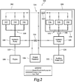
- Hydraulic system 100 includes hydraulic subsystems 102, 104.
- Hydraulic subsystem 102 includes hydraulic pump 106, which is powered by one or more engines 108 via input shaft 110 and/or an interconnect gearbox (not shown).
- Hydraulic subsystem 102 includes a set of hydraulic-powered components 112, 114, 116 in fluid communication with hydraulic pump 106.
- Hydraulic pump 106 pumps hydraulic fluid, which is shared between hydraulic subsystems 102, 104, to hydraulic-powered components 112, 114, 116 via pressure lines 118.
- the term "set" encompasses a quantity of one or more.
- Hydraulic subsystem 104 includes hydraulic pump 120, which is powered by auxiliary power unit 122 via input shaft 124.
- auxiliary power unit 122 may be an electrically-startable gas-powered engine.
- Hydraulic subsystem 104 includes a second set of hydraulic-powered components 126, 128, 130 in fluid communication with hydraulic pump 120.
- Hydraulic pump 120 pumps hydraulic fluid to hydraulic-powered components 126, 128, 130 via pressure lines 132.
- Hydraulic pumps 106, 120 may each operate at any operating pressure, including an operating pressure in a range between 2,500 and 3,500 pounds per square inch, such as 3000 pounds per square inch. Hydraulic pumps 106, 120 may be any type of hydraulic pump, such as a variable displacement constant pressure hydraulic pump.
- Hydraulic system 100 includes shared return line subsystem 134 in fluid communication with the first and second hydraulic subsystems 102, 104, thereby providing fluid communication between the first and second hydraulic subsystems 102, 104. Hydraulic system 100 also includes shared reservoir 136, which is in fluid communication with shared return line subsystem 134 and is shared by hydraulic subsystems 102, 104. Shared reservoir 136 stores hydraulic fluid that is used by first and second hydraulic subsystems 102, 104. Shared return line subsystem 134 returns the hydraulic fluid from hydraulic-powered components 112, 114, 116, 126, 128, 130 to hydraulic pumps 106, 120 and shared reservoir 136 so that the hydraulic fluid may recirculate through hydraulic system 100.
- hydraulic subsystem 102 may be a flight essential hydraulic subsystem and hydraulic system 104 may be a non-flight essential hydraulic subsystem by which only hydraulic subsystem 102 includes hydraulic-powered components 112, 114, 116 that are essential during flight.
- hydraulic-powered components 126, 128, 130 of hydraulic subsystem 104 may be components that are not essential during flight, but are instead used during ground operations and pre-flight checks. Partitioning the functionality of hydraulic subsystems 102, 104 in this manner may be advantageous because of the shared mode failures resulting from the use of shared components, such as shared return line subsystem 134 and shared reservoir 136.
- hydraulic subsystems 102, 104 may be functionally and temporally independent in that each hydraulic subsystem performs different respective functions non-simultaneously. In other embodiments, hydraulic subsystems 102, 104 may be temporally independent such that they are utilized non-simultaneously, but have fully or partially overlapping functionality.
- hydraulic system 100 may be employed to allow hydraulic pump 106 to power hydraulic-powered components 126, 128, 130 and/or hydraulic pump 120 to power hydraulic-powered components 112, 114, 116.
- hydraulic-powered components 112, 114, 116 are flight essential components, such as flight control actuators
- the fluid pressure produced by hydraulic pump 120 may be diverted to hydraulic-powered components 112, 114, 116 in certain circumstances, such as in an emergency or during ground operations.
- hydraulic system 100 is illustrated as including two hydraulic subsystems 102, 104, in other embodiments hydraulic system 100 may include three or more hydraulic subsystems that share shared return line subsystem 134, shared reservoir 136 or other components.
- hydraulic subsystem 104 may be an isolated hydraulic subsystem 138 that is isolated from the remainder of hydraulic system 100, including hydraulic subsystem 102, so that a failure in hydraulic subsystem 104 does not affect the remainder of hydraulic system 100, including any flight essential hydraulic subsystems.
- the isolation of hydraulic subsystem 104 may be implemented using check valve 140, selector valve 142 and/or other components. Selector valve 142 may be opened or closed depending on whether hydraulic subsystem 104 is being utilized.
- shared return line subsystem 134 may include check valve 144 so that hydraulic fluid used by hydraulic-powered components 112, 114, 116, 126, 128, 130 may be returned either directly to hydraulic pump 120 or indirectly to hydraulic pump 120 via shared reservoir 136, while hydraulic fluid is returned to hydraulic pump 106 via shared reservoir 136.
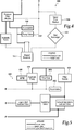
- Hydraulic system 200 includes a flight control hydraulic subsystem 202, which is a flight essential hydraulic subsystem, and a ground checkout and engine starting hydraulic subsystem 204, which is a non-flight essential hydraulic subsystem.
- Flight control hydraulic subsystem 202 includes a hydraulic power generation circuit 206 that includes hydraulic pump 208 powered by engine 210 via gearbox 212.
- Hydraulic pump 208 provides hydraulic pump pressure to pressure filter module 214, through which system pressure is provided to pressure lines 216.
- pressure filter module 214 may be equipped with a pressure transducer that supports a cockpit indication of system pressure and a mechanical delta pressure indicator that provides an indication of a dirty filter.
- Hydraulic system 200 includes shared reservoir 218, which stores hydraulic fluid and is in fluid communication with both flight control hydraulic subsystem 202 and ground checkout and engine starting hydraulic subsystem 204. Hydraulic pump 208 may receive hydraulic fluid from shared reservoir 218 via hydraulic pump suction line 220.
- Hydraulic pump 208 may be in fluid communication with a return filter module 222 via a hydraulic pump case drain line 224.
- Return filter module 222 includes system and pump case drain fluid filters.
- Return filter module 222 may also be equipped with a temperature sensor that supports a cockpit indication of system fluid temperature as well as filter mechanical delta pressure indicators for both the return and case drain filters. The delta pressure indicators may provide an indication of a dirty filter. Hydraulic fluid may be returned to shared reservoir 218 from return filter module 222 via reservoir inlet line 226.
- the hydraulic-powered components of flight control hydraulic subsystem 202 include nacelle flight control actuators 228, 230, wing flight control actuators 232, 234 and tail section flight control actuators 236.
- Nacelle flight control actuators 228, 230 may control one or more flight control surfaces on the nacelles of, for example, a tiltrotor aircraft such as that illustrated in figures 1A-1B .
- the nacelle flight control actuators 228, 230 may also be used to control a pylon conversion actuator on the nacelles of a tiltrotor aircraft to change between VTOL and forward flight mode, as described in figures 1A-1B .
- Wing flight control actuators 232, 234 may control one or more flight control surfaces on a wing of an aircraft, such as wing 16 illustrated in figures 1A-1B .
- Tail section flight control actuators 236 may be used to control one or more flight control surfaces on the tail section of an aircraft, such as tail members 14a, 14b of tail section 14 illustrated in figures 1A-1B .
- the flight control actuators of flight control hydraulic subsystem 202 may control any flight control surface, such as ailerons, flaperons, spoilers, elevators, rudders, ruddervators or any combination thereof.
- Other hydraulic-powered components that may be powered by flight control hydraulic subsystem 202 include one or more rotor swashplate flight control actuators or actuators to control tail wheel steering or wheel brakes.
- Flight control actuators 228, 230, 232, 234, 236 may be any type of actuator, such as one or more single system linear electro-hydraulic servoactuators.
- flight control hydraulic subsystem 202 may have a duplex or triplex redundant architecture as a safety measure in case of component failure.
- hydraulic system 200 includes shared return line subsystem 238, which recirculates hydraulic fluid back to flight control hydraulic subsystem 202 and ground checkout and engine starting hydraulic subsystem 204.
- Ground checkout and engine starting hydraulic subsystem 204 includes hydraulic pump 240, which is powered by auxiliary power unit 242.
- Hydraulic pump 240 may obtain hydraulic fluid from shared return line subsystem 238 via hydraulic pump filter module 244 and hydraulic pump suction line 246. Hydraulic pump 240 may drain into hydraulic pump filter module 244 via hydraulic pump case drain line 248. Hydraulic pump 240 pumps hydraulic fluid at a particular pressure to one or more ground operation components, such as engine start hydraulic motors 250, 252.
- Engine start hydraulic motors 250, 252 may include one or more engine start valves and be used to start the engines in the nacelles of a tiltrotor aircraft, such as those described in figures 1A-1B .
- Flight control hydraulic subsystem 202 and ground checkout and engine starting hydraulic subsystem 204 and in particular flight control actuators 228, 230, 232, 234, 236 and engine start hydraulic motors 250, 252, return hydraulic fluid back into shared return line subsystem 238.
- Shared return line subsystem 238 may then recirculate the hydraulic fluid back to hydraulic pump 208, hydraulic pump 240 and/or shared reservoir 218.
- Engine start circuit 254 of ground checkout and engine starting hydraulic subsystem 204 may include one or more control valves and dedicated high-pressure routings to provide fluid power to engine start hydraulic motors 250, 252.
- Ground checkout and engine starting hydraulic subsystem 204 may power engine start hydraulic motors 250, 252 when switching valve 256, engine start isolation valve 258 and the engine start valves at engine start hydraulic motors 250, 252 are set in appropriate positions.
- Switching valve 256 may also be positioned to allow fluid pressure from hydraulic pump 208 of flight control hydraulic subsystem 202 to power engine start hydraulic motors 250, 252.
- engine start circuit 254 may be powered by a ground cart.
- a ground operations isolation valve 260 may be selectively opened to allow hydraulic pump 240 to provide hydraulic fluid to flight control actuators 228, 230, 232, 234, 236 via pressure line 262 during ground operations.
- hydraulic pump 240 is capable of delivering fluid pressure to flight control actuators 228, 230, 232, 234, 236 for flight control functional checks, including pre-flight checks, either when auxiliary power unit 242 is running or when ground power is connected from a hydraulic cart.
- either or both of hydraulic power generation circuit 206 or engine start circuit 254 may utilize one or more accumulators and/or heat exchangers to fine tune the operating pressure and hydraulic fluid temperature.
- engine start circuit 254 may be located in the fuselage of an aircraft. Flight control hydraulic subsystem 202 and ground checkout and engine starting hydraulic subsystem 204 may be isolated from one another using one or more check valves 264, 266, 268, 270, switching valve 256 or other components such that if, for example, one of the pressure lines of ground checkout and engine starting hydraulic subsystem 204 failed, then flight control hydraulic subsystem 202 would remain in a fully functional condition. By isolating the hydraulic subsystems in the aircraft from one another in this manner, the overall safety and reliability of the aircraft is improved.
- Hydraulic power generation circuit 300 may be used in lieu of or in combination with hydraulic power generation circuit 206 in figure 3 .
- Hydraulic power generation circuit 300 includes additional components not shown for hydraulic power generation circuit 206 in figure 3 .
- hydraulic power generation circuit 300 includes heat exchanger 302, which cools hydraulic fluid flowing into shared reservoir 304 from return filter module 306. Heat exchanger 302 may be equipped with a thermostat and pressure relief valve to bypass the core when cooling the hydraulic fluid is not required or in the event that the core becomes clogged.
- Hydraulic power generation circuit 300 also includes a bootstrap reservoir accumulator 308 used to maintain the reservoir bootstrap return pressure.
- Hydraulic power generation circuit 300 also includes an accumulator dump valve 310 utilized to service accumulator 308 and relieve bootstrap pressure prior to maintenance. Dump valve 310 may also incorporate a high pressure relief feature.
- Engine start circuit 400 may be used in lieu of or in combination with engine start circuit 254 in figure 3 .
- Engine start circuit 400 includes pump inlet accumulator 402, flow fuse 404 and filter module 406.
- Accumulator 402 is used to maintain pump inlet pressure greater than a pump manufacturer minimum, and flow fuse 404 is used to unload hydraulic pump 408 while auxiliary power unit 410 is starting.
Landscapes
- Engineering & Computer Science (AREA)
- Aviation & Aerospace Engineering (AREA)
- Physics & Mathematics (AREA)
- Fluid Mechanics (AREA)
- Automation & Control Theory (AREA)
- Mechanical Engineering (AREA)
- Chemical & Material Sciences (AREA)
- Combustion & Propulsion (AREA)
- General Engineering & Computer Science (AREA)
- Fluid-Pressure Circuits (AREA)
Abstract
Description
- The present disclosure relates, in general, to hydraulic systems for an aircraft and, in particular, to aircraft hydraulic systems with two or more hydraulic subsystems having shared components.
- Hydraulic systems are commonly employed on aircraft to perform a variety of different operations. For example, hydraulic systems may be used to start one or more engines, move control surfaces and apply wheel brakes, among other things. Aircraft sometimes use multiple independent hydraulic circuits that employ altogether different componentry, even in cases in which independent componentry is redundant or unnecessary. The redundant use of hydraulic components increases the weight of the aircraft, adds to aircraft cost and occupies valuable space within the aircraft. Accordingly, a need has arisen for a hydraulic system having two or more hydraulic subsystems that share one or more components, thereby mitigating the aforementioned problems, among others, found in current hydraulic systems.
- In a first aspect, the present disclosure is directed to a hydraulic system for an aircraft having an engine and an auxiliary power unit. The hydraulic system includes a first hydraulic subsystem including a first hydraulic pump and a first set of hydraulic-powered components in fluid communication with the first hydraulic pump. The first hydraulic pump is powered by the engine to pump shared hydraulic fluid to the first set of hydraulic-powered components. The hydraulic system includes a second hydraulic subsystem including a second hydraulic pump and a second set of hydraulic-powered components in fluid communication with the second hydraulic pump. The second hydraulic pump is powered by the auxiliary power unit to pump the shared hydraulic fluid to the second set of hydraulic-powered components. The hydraulic system also includes a shared return line subsystem in fluid communication with the first and second hydraulic subsystems to return the shared hydraulic fluid from the first and second sets of hydraulic-powered components to the first and second hydraulic pumps.
- In some embodiments, the hydraulic system may include a shared reservoir in fluid communication with the shared return line subsystem, the shared reservoir adapted to store the shared hydraulic fluid usable by the first and second hydraulic subsystems. In certain embodiments, the shared return line subsystem may be adapted to return the shared hydraulic fluid to the first hydraulic pump, the second hydraulic pump and the shared reservoir. In such embodiments, the shared return line subsystem may return the shared hydraulic fluid to the first hydraulic pump via the shared reservoir. In some embodiments, the first hydraulic subsystem may include a first set of pressure lines providing fluid communication between the first hydraulic pump and the first set of hydraulic-powered components, and the second hydraulic subsystem may include a second set of pressure lines providing fluid communication between the second hydraulic pump and the second set of hydraulic-powered components. In certain embodiments, one of the first or second hydraulic subsystems may be a flight essential hydraulic subsystem and the other of the first or second hydraulic subsystems may be a non-flight essential hydraulic subsystem. In such embodiments, the first hydraulic subsystem may be the flight essential hydraulic subsystem and the second hydraulic subsystem may be the non-flight essential hydraulic subsystem. In some embodiments, the flight essential hydraulic subsystem may include a flight control hydraulic subsystem and the non-flight essential hydraulic subsystem may include a ground checkout and engine starting hydraulic subsystem.
- In certain embodiments, the first hydraulic subsystem may include a flight control hydraulic subsystem. In such embodiments, the first set of hydraulic-powered components of the flight control hydraulic subsystem may include at least one flight control actuator, such as a wing flight control actuator, a tail section flight control actuator or a nacelle flight control actuator, each adapted to move a flight control surface. In some embodiments, the second hydraulic subsystem may include a ground checkout and engine starting hydraulic subsystem. In such embodiments, the second set of hydraulic-powered components of the ground checkout and engine starting hydraulic subsystem may include at least one ground operation component, such as an engine start hydraulic motor. In certain embodiments, the ground checkout and engine starting hydraulic subsystem may include a ground operations isolation valve downstream of the second hydraulic pump, the ground operations isolation valve adapted to be selectively opened to allow the second hydraulic pump to provide the shared hydraulic fluid to the first set of hydraulic-powered components during ground operations. In some embodiments, the first hydraulic subsystem may be in fluid communication with the second hydraulic subsystem via the shared return line subsystem. In certain embodiments, the hydraulic system may include at least one switching valve downstream of the first and second hydraulic pumps, the at least one switching valve movable into a plurality of positions including a first position and a second position. In the first position the at least one switching valve may allow the first hydraulic pump to provide the shared hydraulic fluid to the second set of hydraulic-powered components, and in the second position the at least one switching valve may allow the second hydraulic pump to provide the shared hydraulic fluid to the first set of hydraulic-powered components. In some embodiments, at least one of the first or second hydraulic subsystems may have an operating pressure of between about 2500 and 3500 pounds per square inch.
- In a second aspect, the present disclosure is directed to an aircraft including one or more engines, an auxiliary power unit and a hydraulic system. The hydraulic system includes a first hydraulic subsystem including a first hydraulic pump and a first set of hydraulic-powered components in fluid communication with the first hydraulic pump. The first hydraulic pump is powered by the one or more engines to pump shared hydraulic fluid to the first set of hydraulic-powered components. The hydraulic system includes a second hydraulic subsystem including a second hydraulic pump and a second set of hydraulic-powered components in fluid communication with the second hydraulic pump. The second hydraulic pump is powered by the auxiliary power unit to pump the shared hydraulic fluid to the second set of hydraulic-powered components. The hydraulic system also includes a shared return line subsystem in fluid communication with the first and second hydraulic subsystems to return the shared hydraulic fluid from the first and second sets of hydraulic-powered components to the first and second hydraulic pumps.
- In some embodiments, the aircraft may be a tiltrotor aircraft. In certain embodiments, the tiltrotor aircraft may include a wing having first and second ends and first and second nacelles coupled to the first and second ends of the wing, respectively, the first and second nacelles each having one or more flight control surfaces. The first set of hydraulic-powered components of the first hydraulic subsystem may include a first nacelle flight control actuator adapted to control the one or more flight control surfaces of the first nacelle and a second nacelle flight control actuator adapted to control the one or more flight control surfaces of the second nacelle. In some embodiments, the tiltrotor aircraft may include a wing having first and second ends and first and second nacelles coupled to the first and second ends of the wing, respectively, the first and second nacelles each having an engine. The second set of hydraulic-powered components of the second hydraulic subsystem may include a first engine start hydraulic motor adapted to start the engine of the first nacelle and a second engine start hydraulic motor adapted to start the engine of the second nacelle.
- For a more complete understanding of the features and advantages of the present disclosure, reference is now made to the detailed description along with the accompanying figures in which corresponding numerals in the different figures refer to corresponding parts and in which:
-
Figures 1A-1B are schematic illustrations of a tiltrotor aircraft utilizing a hydraulic system in accordance with embodiments of the present disclosure; -
Figure 2 is a schematic illustration of a hydraulic system having shared components in accordance with embodiments of the present disclosure; -
Figure 3 is a schematic illustration of a hydraulic system having shared components in accordance with embodiments of the present disclosure; -
Figure 4 is a schematic illustration of a hydraulic power generation circuit in accordance with embodiments of the present disclosure; and -
Figure 5 is a schematic illustration of an engine start circuit in accordance with embodiments of the present disclosure. - While the making and using of various embodiments of the present disclosure are discussed in detail below, it should be appreciated that the present disclosure provides many applicable inventive concepts, which can be embodied in a wide variety of specific contexts. The specific embodiments discussed herein are merely illustrative and do not delimit the scope of the present disclosure. In the interest of clarity, all features of an actual implementation may not be described in this specification. It will of course be appreciated that in the development of any such actual embodiment, numerous implementation-specific decisions must be made to achieve the developer's specific goals, such as compliance with system-related and business-related constraints, which will vary from one implementation to another. Moreover, it will be appreciated that such a development effort might be complex and time-consuming but would nevertheless be a routine undertaking for those of ordinary skill in the art having the benefit of this disclosure.
- In the specification, reference may be made to the spatial relationships between various components and to the spatial orientation of various aspects of components as the devices are depicted in the attached drawings. However, as will be recognized by those skilled in the art after a complete reading of the present disclosure, the devices, members, apparatuses, and the like described herein may be positioned in any desired orientation. Thus, the use of terms such as "above," "below," "upper," "lower" or other like terms to describe a spatial relationship between various components or to describe the spatial orientation of aspects of such components should be understood to describe a relative relationship between the components or a spatial orientation of aspects of such components, respectively, as the devices described herein may be oriented in any desired direction.
- Referring to
figures 1A-1B in the drawings, a tiltrotor aircraft is schematically illustrated and generally designated 10.Tiltrotor aircraft 10 includes afuselage 12 and atail section 14 including rotatably mountedtail members wing 16 is supported byfuselage 12. Located at outboard ends ofwing 16 arepropulsion assemblies Propulsion assembly 18a includes a fixednacelle 20a that houses anengine 22 and a transmission. In addition,propulsion assembly 18a includes apylon assembly 24a that is rotatable relative to fixednacelle 20a between a generally horizontal orientation, as best seen infigure 1A , and a generally vertical orientation, as best seen in figure IB.Propulsion assembly 18a also includes aproprotor assembly 26a that is rotatable relative topylon assembly 24a responsive to torque and rotational energy provided by a rotor hub assembly and drive system mechanically coupled toengine 22 and the transmission. Similarly,propulsion assembly 18b includes a fixednacelle 20b that houses an engine and transmission, apylon assembly 24b that is rotatable relative to fixednacelle 20b and aproprotor assembly 26b that is rotatable relative topylon assembly 24b responsive to torque and rotational energy provided via a rotor hub assembly and drive system mechanically coupled to the engine and transmission housed by fixednacelle 20b. As used herein, the term "coupled" may include direct or indirect coupling by any means, including moving and/or non-moving mechanical connections. -
Figure 1A illustratestiltrotor aircraft 10 in airplane or forward flight mode, in whichproprotor assemblies thrust enabling wing 16 to provide a lifting force responsive to forward airspeed, such thattiltrotor aircraft 10 flies much like a conventional propeller driven aircraft.Figure 1B illustratestiltrotor aircraft 10 in helicopter or vertical takeoff and landing (VTOL) flight mode, in whichproprotor assemblies tiltrotor aircraft 10 flies much like a conventional helicopter. It should be appreciated thattiltrotor aircraft 10 can be operated such thatproprotor assemblies tiltrotor aircraft 10 has been described as having one engine in each fixednacelle fuselage 12 that provides torque and rotational energy to bothproprotor assemblies -
Tiltrotor aircraft 10 has ahydraulic system 28 that includeshydraulic subsystems Hydraulic subsystems tiltrotor aircraft 10.Hydraulic subsystems hydraulic subsystem 30 may be powered by either or both of the engines in the nacelles ofpropulsion assemblies tiltrotor aircraft 10.Hydraulic subsystem 32 is powered by anauxiliary power unit 34. To reduce the weight and cost oftiltrotor aircraft 10,hydraulic subsystems hydraulic subsystems return line subsystem 36 and a sharedreservoir 38. Utilizing common plumbing in this manner eliminates unnecessary weight carried by aircraft that have two or more entirely independent hydraulic subsystems that share no componentry. - It should be appreciated that
tiltrotor aircraft 10 is merely illustrative of a variety of aircraft that can implement the embodiments disclosed herein. Indeed,hydraulic system 28 may be utilized on any aircraft that uses hydraulics. Other aircraft implementations can include hybrid aircraft, tiltwing aircraft, quad tiltrotor aircraft, unmanned aircraft, gyrocopters, airplanes, jets, helicopters and the like. As such, those of ordinary skill in the art will recognize thathydraulic system 28 can be integrated into a variety of aircraft configurations. It should be appreciated that even though aircraft are particularly well-suited to implement the embodiments of the present disclosure, non-aircraft vehicles and devices can also implement the embodiments, including, but not limited to, automobiles or land-based vehicles. - Referring to
figure 2 in the drawings, a hydraulic system for an aircraft is schematically illustrated and generally designated 100.Hydraulic system 100 includeshydraulic subsystems Hydraulic subsystem 102 includeshydraulic pump 106, which is powered by one ormore engines 108 viainput shaft 110 and/or an interconnect gearbox (not shown).Hydraulic subsystem 102 includes a set of hydraulic-poweredcomponents hydraulic pump 106.Hydraulic pump 106 pumps hydraulic fluid, which is shared betweenhydraulic subsystems components Hydraulic subsystem 104 includeshydraulic pump 120, which is powered byauxiliary power unit 122 viainput shaft 124. In some embodiments,auxiliary power unit 122 may be an electrically-startable gas-powered engine.Hydraulic subsystem 104 includes a second set of hydraulic-poweredcomponents hydraulic pump 120.Hydraulic pump 120 pumps hydraulic fluid to hydraulic-poweredcomponents Hydraulic pumps Hydraulic pumps -
Hydraulic system 100 includes sharedreturn line subsystem 134 in fluid communication with the first and secondhydraulic subsystems hydraulic subsystems Hydraulic system 100 also includes sharedreservoir 136, which is in fluid communication with sharedreturn line subsystem 134 and is shared byhydraulic subsystems reservoir 136 stores hydraulic fluid that is used by first and secondhydraulic subsystems return line subsystem 134 returns the hydraulic fluid from hydraulic-poweredcomponents hydraulic pumps reservoir 136 so that the hydraulic fluid may recirculate throughhydraulic system 100. In one embodiment,hydraulic subsystem 102 may be a flight essential hydraulic subsystem andhydraulic system 104 may be a non-flight essential hydraulic subsystem by which onlyhydraulic subsystem 102 includes hydraulic-poweredcomponents components hydraulic subsystem 104 may be components that are not essential during flight, but are instead used during ground operations and pre-flight checks. Partitioning the functionality ofhydraulic subsystems return line subsystem 134 and sharedreservoir 136. In some embodiments,hydraulic subsystems hydraulic subsystems - To further enhance the flexibility of
hydraulic system 100, one or more valves or other hydraulic components (not shown) may be employed to allowhydraulic pump 106 to power hydraulic-poweredcomponents hydraulic pump 120 to power hydraulic-poweredcomponents components hydraulic pump 120 may be diverted to hydraulic-poweredcomponents hydraulic system 100 is illustrated as including twohydraulic subsystems hydraulic system 100 may include three or more hydraulic subsystems that share sharedreturn line subsystem 134, sharedreservoir 136 or other components. Previous aircraft that have employed multiple hydraulic subsystems do so in a way that each hydraulic subsystem is completely independent of one another with no component overlap, thus increasing the weight, cost and volume of the overall hydraulic system. By reducing the need for multiple reservoirs and independent plumbing, the illustrative embodiments mitigate such disadvantages. - In addition,
hydraulic subsystem 104 may be an isolatedhydraulic subsystem 138 that is isolated from the remainder ofhydraulic system 100, includinghydraulic subsystem 102, so that a failure inhydraulic subsystem 104 does not affect the remainder ofhydraulic system 100, including any flight essential hydraulic subsystems. The isolation ofhydraulic subsystem 104 may be implemented usingcheck valve 140,selector valve 142 and/or other components.Selector valve 142 may be opened or closed depending on whetherhydraulic subsystem 104 is being utilized. In some embodiments, sharedreturn line subsystem 134 may includecheck valve 144 so that hydraulic fluid used by hydraulic-poweredcomponents hydraulic pump 120 or indirectly tohydraulic pump 120 via sharedreservoir 136, while hydraulic fluid is returned tohydraulic pump 106 via sharedreservoir 136. - Referring to
figure 3 in the drawings, a hydraulic system for an aircraft is schematically illustrated and generally designated 200.Hydraulic system 200 includes a flight controlhydraulic subsystem 202, which is a flight essential hydraulic subsystem, and a ground checkout and engine startinghydraulic subsystem 204, which is a non-flight essential hydraulic subsystem. Flight controlhydraulic subsystem 202 includes a hydraulicpower generation circuit 206 that includeshydraulic pump 208 powered byengine 210 viagearbox 212.Hydraulic pump 208 provides hydraulic pump pressure to pressurefilter module 214, through which system pressure is provided to pressure lines 216. In one example,pressure filter module 214 may be equipped with a pressure transducer that supports a cockpit indication of system pressure and a mechanical delta pressure indicator that provides an indication of a dirty filter.Hydraulic system 200 includes sharedreservoir 218, which stores hydraulic fluid and is in fluid communication with both flight controlhydraulic subsystem 202 and ground checkout and engine startinghydraulic subsystem 204.Hydraulic pump 208 may receive hydraulic fluid from sharedreservoir 218 via hydraulicpump suction line 220. -
Hydraulic pump 208 may be in fluid communication with areturn filter module 222 via a hydraulic pumpcase drain line 224.Return filter module 222 includes system and pump case drain fluid filters.Return filter module 222 may also be equipped with a temperature sensor that supports a cockpit indication of system fluid temperature as well as filter mechanical delta pressure indicators for both the return and case drain filters. The delta pressure indicators may provide an indication of a dirty filter. Hydraulic fluid may be returned to sharedreservoir 218 fromreturn filter module 222 viareservoir inlet line 226. - The hydraulic-powered components of flight control
hydraulic subsystem 202 include nacelleflight control actuators flight control actuators flight control actuators 236. Nacelleflight control actuators figures 1A-1B . The nacelleflight control actuators figures 1A-1B . Wingflight control actuators wing 16 illustrated infigures 1A-1B . Tail sectionflight control actuators 236 may be used to control one or more flight control surfaces on the tail section of an aircraft, such astail members tail section 14 illustrated infigures 1A-1B . Indeed, the flight control actuators of flight controlhydraulic subsystem 202 may control any flight control surface, such as ailerons, flaperons, spoilers, elevators, rudders, ruddervators or any combination thereof. Other hydraulic-powered components that may be powered by flight controlhydraulic subsystem 202 include one or more rotor swashplate flight control actuators or actuators to control tail wheel steering or wheel brakes.Flight control actuators hydraulic subsystem 202 may have a duplex or triplex redundant architecture as a safety measure in case of component failure. In addition to sharedreservoir 218,hydraulic system 200 includes sharedreturn line subsystem 238, which recirculates hydraulic fluid back to flight controlhydraulic subsystem 202 and ground checkout and engine startinghydraulic subsystem 204. - Ground checkout and engine starting
hydraulic subsystem 204 includeshydraulic pump 240, which is powered byauxiliary power unit 242.Hydraulic pump 240 may obtain hydraulic fluid from sharedreturn line subsystem 238 via hydraulicpump filter module 244 and hydraulicpump suction line 246.Hydraulic pump 240 may drain into hydraulicpump filter module 244 via hydraulic pumpcase drain line 248.Hydraulic pump 240 pumps hydraulic fluid at a particular pressure to one or more ground operation components, such as engine starthydraulic motors hydraulic motors figures 1A-1B . The hydraulic-powered components of both flight controlhydraulic subsystem 202 and ground checkout and engine startinghydraulic subsystem 204, and in particularflight control actuators hydraulic motors return line subsystem 238. Sharedreturn line subsystem 238 may then recirculate the hydraulic fluid back tohydraulic pump 208,hydraulic pump 240 and/or sharedreservoir 218. -
Engine start circuit 254 of ground checkout and engine startinghydraulic subsystem 204 may include one or more control valves and dedicated high-pressure routings to provide fluid power to engine starthydraulic motors hydraulic subsystem 204 may power engine starthydraulic motors valve 256, engine startisolation valve 258 and the engine start valves at engine starthydraulic motors Switching valve 256 may also be positioned to allow fluid pressure fromhydraulic pump 208 of flight controlhydraulic subsystem 202 to power engine starthydraulic motors engine start circuit 254 may be powered by a ground cart. A groundoperations isolation valve 260 may be selectively opened to allowhydraulic pump 240 to provide hydraulic fluid toflight control actuators pressure line 262 during ground operations. Thus, with groundoperations isolation valve 260 energized and the engines not running,hydraulic pump 240 is capable of delivering fluid pressure toflight control actuators auxiliary power unit 242 is running or when ground power is connected from a hydraulic cart. In some embodiments, either or both of hydraulicpower generation circuit 206 orengine start circuit 254 may utilize one or more accumulators and/or heat exchangers to fine tune the operating pressure and hydraulic fluid temperature. In some embodiments,engine start circuit 254 may be located in the fuselage of an aircraft. Flight controlhydraulic subsystem 202 and ground checkout and engine startinghydraulic subsystem 204 may be isolated from one another using one ormore check valves valve 256 or other components such that if, for example, one of the pressure lines of ground checkout and engine startinghydraulic subsystem 204 failed, then flight controlhydraulic subsystem 202 would remain in a fully functional condition. By isolating the hydraulic subsystems in the aircraft from one another in this manner, the overall safety and reliability of the aircraft is improved. - Referring to
figure 4 in the drawings, a hydraulic power generation circuit is schematically illustrated and generally designated 300. Hydraulicpower generation circuit 300 may be used in lieu of or in combination with hydraulicpower generation circuit 206 infigure 3 . Hydraulicpower generation circuit 300 includes additional components not shown for hydraulicpower generation circuit 206 infigure 3 . In particular, hydraulicpower generation circuit 300 includesheat exchanger 302, which cools hydraulic fluid flowing into sharedreservoir 304 fromreturn filter module 306.Heat exchanger 302 may be equipped with a thermostat and pressure relief valve to bypass the core when cooling the hydraulic fluid is not required or in the event that the core becomes clogged. Hydraulicpower generation circuit 300 also includes abootstrap reservoir accumulator 308 used to maintain the reservoir bootstrap return pressure. Hydraulicpower generation circuit 300 also includes anaccumulator dump valve 310 utilized toservice accumulator 308 and relieve bootstrap pressure prior to maintenance. Dumpvalve 310 may also incorporate a high pressure relief feature. - Referring to
figure 5 of the drawings, an engine start circuit is schematically illustrated and generally designated 400.Engine start circuit 400 may be used in lieu of or in combination withengine start circuit 254 infigure 3 . Included inengine start circuit 400 arepump inlet accumulator 402,flow fuse 404 andfilter module 406.Accumulator 402 is used to maintain pump inlet pressure greater than a pump manufacturer minimum, and flowfuse 404 is used to unloadhydraulic pump 408 whileauxiliary power unit 410 is starting. - The foregoing description of embodiments of the disclosure has been presented for purposes of illustration and description. It is not intended to be exhaustive or to limit the disclosure to the precise form disclosed, and modifications and variations are possible in light of the above teachings or may be acquired from practice of the disclosure. The embodiments were chosen and described in order to explain the principals of the disclosure and its practical application to enable one skilled in the art to utilize the disclosure in various embodiments and with various modifications as are suited to the particular use contemplated. Other substitutions, modifications, changes and omissions may be made in the design, operating conditions and arrangement of the embodiments without departing from the scope of the present disclosure. Such modifications and combinations of the illustrative embodiments as well as other embodiments will be apparent to persons skilled in the art upon reference to the description. It is, therefore, intended that the appended claims encompass any such modifications or embodiments.
Claims (15)
- A hydraulic system for an aircraft having an engine and an auxiliary power unit comprising:a first hydraulic subsystem including a first hydraulic pump and a first set of hydraulic-powered components in fluid communication with the first hydraulic pump, the first hydraulic pump powered by the engine to pump shared hydraulic fluid to the first set of hydraulic-powered components;a second hydraulic subsystem including a second hydraulic pump and a second set of hydraulic-powered components in fluid communication with the second hydraulic pump, the second hydraulic pump powered by the auxiliary power unit to pump the shared hydraulic fluid to the second set of hydraulic-powered components; anda shared return line subsystem in fluid communication with the first and second hydraulic subsystems to return the shared hydraulic fluid from the first and second sets of hydraulic-powered components to the first and second hydraulic pumps.
- The hydraulic system as recited in claim 1 further comprising:a shared reservoir in fluid communication with the shared return line subsystem, the shared reservoir adapted to store the shared hydraulic fluid usable by the first and second hydraulic subsystems.
- The hydraulic system as recited in claim 2 wherein the shared return line subsystem is adapted to return the shared hydraulic fluid to the first hydraulic pump, the second hydraulic pump and the shared reservoir, and optionally or preferably wherein the shared return line subsystem returns the shared hydraulic fluid to the first hydraulic pump via the shared reservoir.
- The hydraulic system as recited in claim 1 or in any preceding claim, wherein the first hydraulic subsystem further comprises a first set of pressure lines providing fluid communication between the first hydraulic pump and the first set of hydraulic-powered components; and
wherein, the second hydraulic subsystem further comprises a second set of pressure lines providing fluid communication between the second hydraulic pump and the second set of hydraulic-powered components. - The hydraulic system as recited in claim 1 or in any preceding claim, wherein one of the first or second hydraulic subsystems is a flight essential hydraulic subsystem and the other of the first or second hydraulic subsystems is a non-flight essential hydraulic subsystem.
- The hydraulic system as recited in claim 5 wherein the first hydraulic subsystem further comprises the flight essential hydraulic subsystem and the second hydraulic subsystem further comprises the non-flight essential hydraulic subsystem, and optionally or preferably wherein the flight essential hydraulic subsystem further comprises a flight control hydraulic subsystem and the non-flight essential hydraulic subsystem further comprises a ground checkout and engine starting hydraulic subsystem.
- The hydraulic system as recited in claim 1 or in any preceding claim, wherein the first hydraulic subsystem further comprises a flight control hydraulic subsystem.
- The hydraulic system as recited in claim 7 wherein the first set of hydraulic-powered components of the flight control hydraulic subsystem further comprises at least one flight control actuator each adapted to move a flight control surface, and optionally or preferably wherein the at least one flight control actuator includes at least one of a wing flight control actuator, a tail section flight control actuator or a nacelle flight control actuator.
- The hydraulic system as recited in claim 1 or in any preceding claim, wherein the second hydraulic subsystem further comprises a ground checkout and engine starting hydraulic subsystem.
- The hydraulic system as recited in claim 9 wherein the second set of hydraulic-powered components of the ground checkout and engine starting hydraulic subsystem further comprises at least one ground operation component, and optionally or preferably wherein the at least one ground operation component further comprises at least one engine start hydraulic motor.
- The hydraulic system as recited in claim 9 or in claim 10 wherein the ground checkout and engine starting hydraulic subsystem further comprises a ground operations isolation valve downstream of the second hydraulic pump, the ground operations isolation valve adapted to be selectively opened to allow the second hydraulic pump to provide the shared hydraulic fluid to the first set of hydraulic-powered components during ground operations.
- The hydraulic system as recited in claim 1 or in any preceding claim further comprising:at least one switching valve downstream of the first and second hydraulic pumps, the at least one switching valve movable into a plurality of positions including a first position and a second position;wherein, in the first position, the at least one switching valve allows the first hydraulic pump to provide the shared hydraulic fluid to the second set of hydraulic-powered components; andwherein, in the second position, the at least one switching valve allows the second hydraulic pump to provide the shared hydraulic fluid to the second set of hydraulic-powered components.
- An aircraft comprising:one or more engines;an auxiliary power unit; anda hydraulic system comprising:a first hydraulic subsystem including a first hydraulic pump and a first set of hydraulic-powered components in fluid communication with the first hydraulic pump, the first hydraulic pump powered by the one or more engines to pump shared hydraulic fluid to the first set of hydraulic-powered components;a second hydraulic subsystem including a second hydraulic pump and a second set of hydraulic-powered components in fluid communication with the second hydraulic pump, the second hydraulic pump powered by the auxiliary power unit to pump the shared hydraulic fluid to the second set of hydraulic-powered components; anda shared return line subsystem in fluid communication with the first and second hydraulic subsystems to return the shared hydraulic fluid from the first and second sets of hydraulic-powered components to the first and second hydraulic pumps.
- The aircraft as recited in claim 13 wherein the aircraft further comprises a tiltrotor aircraft.
- The aircraft as recited in claim 14 further comprising:(i) a wing having first and second ends; and
first and second nacelles coupled to the first and second ends of the wing, respectively, the first and second nacelles each having one or more flight control surfaces;
wherein, the first set of hydraulic-powered components of the first hydraulic subsystem further comprises a first nacelle flight control actuator adapted to control the one or more flight control surfaces of the first nacelle and a second nacelle flight control actuator adapted to control the one or more flight control surfaces of the second nacelle; and/or(ii) a wing having first and second ends; andfirst and second nacelles coupled to the first and second ends of the wing, respectively, the first and second nacelles each having an engine;
wherein, the second set of hydraulic-powered components of the second hydraulic subsystem further comprises a first engine start hydraulic motor adapted to start the engine of the first nacelle and a second engine start hydraulic motor adapted to start the engine of the second nacelle.
Applications Claiming Priority (1)
| Application Number | Priority Date | Filing Date | Title |
|---|---|---|---|
| US15/466,655 US10570931B2 (en) | 2017-03-22 | 2017-03-22 | Aircraft hydraulic systems having shared components |
Publications (2)
| Publication Number | Publication Date |
|---|---|
| EP3378763A1 true EP3378763A1 (en) | 2018-09-26 |
| EP3378763B1 EP3378763B1 (en) | 2019-01-30 |
Family
ID=61187188
Family Applications (1)
| Application Number | Title | Priority Date | Filing Date |
|---|---|---|---|
| EP18155552.5A Active EP3378763B1 (en) | 2017-03-22 | 2018-02-07 | Aircraft hydraulic systems having shared components |
Country Status (2)
| Country | Link |
|---|---|
| US (1) | US10570931B2 (en) |
| EP (1) | EP3378763B1 (en) |
Families Citing this family (7)
| Publication number | Priority date | Publication date | Assignee | Title |
|---|---|---|---|---|
| US20190351994A1 (en) * | 2018-05-16 | 2019-11-21 | Richard Michael Truhill | Retractable aircraft control surface |
| US11280398B2 (en) * | 2018-07-02 | 2022-03-22 | Textron Innovations Inc. | Lubrication management systems for tiltrotor aircraft |
| EP3674545B1 (en) | 2018-12-31 | 2022-09-21 | Goodrich Actuation Systems Limited | Tilt rotor control |
| JP7692719B2 (en) * | 2021-03-31 | 2025-06-16 | 本田技研工業株式会社 | aircraft |
| US12043400B2 (en) * | 2022-03-29 | 2024-07-23 | Toyota Motor Engineering & Manufacturing North America, Inc. | Cooling system for aircraft components including ram chute body and relatively rotatable air conduit |
| US12312070B2 (en) | 2023-06-14 | 2025-05-27 | Textron Innovations Inc. | Hydraulic energy retention |
| US12687156B2 (en) * | 2024-08-15 | 2026-07-21 | The Boeing Company | Accumulator for prevention of hydraulic pump cavitation |
Citations (3)
| Publication number | Priority date | Publication date | Assignee | Title |
|---|---|---|---|---|
| FR2224657A1 (en) * | 1973-04-06 | 1974-10-31 | United Aircraft Corp | Servo-mechanism with emergency fluid feed - has auxiliary circuit started when malfunction is detected by valve |
| US20110303785A1 (en) * | 2010-06-10 | 2011-12-15 | Messier-Bugatti-Dowty | Aircraft fitted with an independent drive device |
| US20120233991A1 (en) * | 2011-03-16 | 2012-09-20 | Purdue Research Foundtion | Multi-function machines, hydraulic systems therefor, and methods for their operation |
Family Cites Families (6)
| Publication number | Priority date | Publication date | Assignee | Title |
|---|---|---|---|---|
| US5100082A (en) * | 1987-09-17 | 1992-03-31 | The Boeing Company | Hydraulic power supplies |
| US5768973A (en) * | 1996-12-27 | 1998-06-23 | Cochran; Gary | Hydraulic line and valve assembly for construction vehicle auxiliary implements |
| US6618659B1 (en) * | 2003-01-14 | 2003-09-09 | New Holland North America, Inc. | Boom/bucket hydraulic fluid sharing method |
| CA2754206C (en) * | 2009-03-12 | 2019-04-09 | Bell Helicopter Textron Inc. | Wing extension control surface |
| US9567070B2 (en) * | 2013-03-15 | 2017-02-14 | Bell Helicopter Textron Inc. | Tiltrotor control system with two rise/fall actuators |
| US10106251B2 (en) * | 2014-09-15 | 2018-10-23 | Bell Helicopter Textron Inc. | Variable anhedral tip rotor blade |
-
2017
- 2017-03-22 US US15/466,655 patent/US10570931B2/en active Active
-
2018
- 2018-02-07 EP EP18155552.5A patent/EP3378763B1/en active Active
Patent Citations (3)
| Publication number | Priority date | Publication date | Assignee | Title |
|---|---|---|---|---|
| FR2224657A1 (en) * | 1973-04-06 | 1974-10-31 | United Aircraft Corp | Servo-mechanism with emergency fluid feed - has auxiliary circuit started when malfunction is detected by valve |
| US20110303785A1 (en) * | 2010-06-10 | 2011-12-15 | Messier-Bugatti-Dowty | Aircraft fitted with an independent drive device |
| US20120233991A1 (en) * | 2011-03-16 | 2012-09-20 | Purdue Research Foundtion | Multi-function machines, hydraulic systems therefor, and methods for their operation |
Also Published As
| Publication number | Publication date |
|---|---|
| EP3378763B1 (en) | 2019-01-30 |
| US20180274563A1 (en) | 2018-09-27 |
| US10570931B2 (en) | 2020-02-25 |
Similar Documents
| Publication | Publication Date | Title |
|---|---|---|
| US10570931B2 (en) | Aircraft hydraulic systems having shared components | |
| EP4237330B1 (en) | Vtol aircraft fan tilting mechanisms and arrangements | |
| US10343767B2 (en) | Hydraulic system and method for a flight control system of an aircraft | |
| EP3693271B1 (en) | Multimode clutch assemblies for rotorcraft | |
| EP2821343B1 (en) | Independent hydraulic control system for rotorcraft secondary rotor | |
| US9334044B2 (en) | Method for generating hydraulic power in an aircraft, use of a hybrid power control unit and drive system | |
| EP3339600B1 (en) | Engine cooling systems for aircraft | |
| US11603209B2 (en) | Aviation hydraulic propulsion system utilizing secondary controlled drives | |
| US8172174B2 (en) | Hybrid electromechanical/hydromechanical actuator and actuation control system | |
| US8567715B2 (en) | Flight control system for an aircraft | |
| EP4234400B1 (en) | Electromechanical actuator pump | |
| EP3317179B1 (en) | Aircraft with distributed hydraulic system | |
| US10787245B2 (en) | Distributed compressor for improved integration and performance of an active fluid flow control system | |
| Maré | Aerospace Actuators 3: European Commercial Aircraft and Tiltrotor Aircraft | |
| US9102402B2 (en) | Landing gear, an aircraft, and a method | |
| JP5905294B2 (en) | Aircraft actuator hydraulic system | |
| US20250250001A1 (en) | Hydraulic energy retention | |
| McGillen et al. | Fluid Power and Control Requirements for the Space Shuttle Orbiting Vehicle | |
| Waterman | The Boeing 767 hydraulic system | |
| CA2984534A1 (en) | Engine cooling systems for aircraft |
Legal Events
| Date | Code | Title | Description |
|---|---|---|---|
| STAA | Information on the status of an ep patent application or granted ep patent |
Free format text: STATUS: EXAMINATION IS IN PROGRESS |
|
| PUAI | Public reference made under article 153(3) epc to a published international application that has entered the european phase |
Free format text: ORIGINAL CODE: 0009012 |
|
| 17P | Request for examination filed |
Effective date: 20180207 |
|
| AK | Designated contracting states |
Kind code of ref document: A1 Designated state(s): AL AT BE BG CH CY CZ DE DK EE ES FI FR GB GR HR HU IE IS IT LI LT LU LV MC MK MT NL NO PL PT RO RS SE SI SK SM TR |
|
| AX | Request for extension of the european patent |
Extension state: BA ME |
|
| RIC1 | Information provided on ipc code assigned before grant |
Ipc: B64C 13/42 20060101ALI20180924BHEP Ipc: B64C 27/28 20060101ALN20180924BHEP Ipc: B64C 29/00 20060101ALN20180924BHEP Ipc: B64C 13/40 20060101AFI20180924BHEP Ipc: B64D 41/00 20060101ALI20180924BHEP Ipc: F15B 18/00 20060101ALI20180924BHEP |
|
| GRAP | Despatch of communication of intention to grant a patent |
Free format text: ORIGINAL CODE: EPIDOSNIGR1 |
|
| STAA | Information on the status of an ep patent application or granted ep patent |
Free format text: STATUS: GRANT OF PATENT IS INTENDED |
|
| RIC1 | Information provided on ipc code assigned before grant |
Ipc: B64D 41/00 20060101ALI20181004BHEP Ipc: B64C 27/28 20060101ALN20181004BHEP Ipc: B64C 29/00 20060101ALN20181004BHEP Ipc: B64C 13/40 20060101AFI20181004BHEP Ipc: B64C 13/42 20060101ALI20181004BHEP Ipc: F15B 18/00 20060101ALI20181004BHEP |
|
| INTG | Intention to grant announced |
Effective date: 20181105 |
|
| GRAS | Grant fee paid |
Free format text: ORIGINAL CODE: EPIDOSNIGR3 |
|
| GRAA | (expected) grant |
Free format text: ORIGINAL CODE: 0009210 |
|
| STAA | Information on the status of an ep patent application or granted ep patent |
Free format text: STATUS: THE PATENT HAS BEEN GRANTED |
|
| AK | Designated contracting states |
Kind code of ref document: B1 Designated state(s): AL AT BE BG CH CY CZ DE DK EE ES FI FR GB GR HR HU IE IS IT LI LT LU LV MC MK MT NL NO PL PT RO RS SE SI SK SM TR |
|
| REG | Reference to a national code |
Ref country code: GB Ref legal event code: FG4D |
|
| REG | Reference to a national code |
Ref country code: CH Ref legal event code: EP |
|
| REG | Reference to a national code |
Ref country code: AT Ref legal event code: REF Ref document number: 1093042 Country of ref document: AT Kind code of ref document: T Effective date: 20190215 |
|
| REG | Reference to a national code |
Ref country code: IE Ref legal event code: FG4D |
|
| REG | Reference to a national code |
Ref country code: DE Ref legal event code: R096 Ref document number: 602018000004 Country of ref document: DE |
|
| REG | Reference to a national code |
Ref country code: LT Ref legal event code: MG4D |
|
| REG | Reference to a national code |
Ref country code: NL Ref legal event code: MP Effective date: 20190130 |
|
| PG25 | Lapsed in a contracting state [announced via postgrant information from national office to epo] |
Ref country code: SE Free format text: LAPSE BECAUSE OF FAILURE TO SUBMIT A TRANSLATION OF THE DESCRIPTION OR TO PAY THE FEE WITHIN THE PRESCRIBED TIME-LIMIT Effective date: 20190130 Ref country code: PT Free format text: LAPSE BECAUSE OF FAILURE TO SUBMIT A TRANSLATION OF THE DESCRIPTION OR TO PAY THE FEE WITHIN THE PRESCRIBED TIME-LIMIT Effective date: 20190530 Ref country code: ES Free format text: LAPSE BECAUSE OF FAILURE TO SUBMIT A TRANSLATION OF THE DESCRIPTION OR TO PAY THE FEE WITHIN THE PRESCRIBED TIME-LIMIT Effective date: 20190130 Ref country code: LT Free format text: LAPSE BECAUSE OF FAILURE TO SUBMIT A TRANSLATION OF THE DESCRIPTION OR TO PAY THE FEE WITHIN THE PRESCRIBED TIME-LIMIT Effective date: 20190130 Ref country code: FI Free format text: LAPSE BECAUSE OF FAILURE TO SUBMIT A TRANSLATION OF THE DESCRIPTION OR TO PAY THE FEE WITHIN THE PRESCRIBED TIME-LIMIT Effective date: 20190130 Ref country code: PL Free format text: LAPSE BECAUSE OF FAILURE TO SUBMIT A TRANSLATION OF THE DESCRIPTION OR TO PAY THE FEE WITHIN THE PRESCRIBED TIME-LIMIT Effective date: 20190130 Ref country code: NO Free format text: LAPSE BECAUSE OF FAILURE TO SUBMIT A TRANSLATION OF THE DESCRIPTION OR TO PAY THE FEE WITHIN THE PRESCRIBED TIME-LIMIT Effective date: 20190430 |
|
| REG | Reference to a national code |
Ref country code: AT Ref legal event code: MK05 Ref document number: 1093042 Country of ref document: AT Kind code of ref document: T Effective date: 20190130 |
|
| PG25 | Lapsed in a contracting state [announced via postgrant information from national office to epo] |
Ref country code: IS Free format text: LAPSE BECAUSE OF FAILURE TO SUBMIT A TRANSLATION OF THE DESCRIPTION OR TO PAY THE FEE WITHIN THE PRESCRIBED TIME-LIMIT Effective date: 20190530 Ref country code: NL Free format text: LAPSE BECAUSE OF FAILURE TO SUBMIT A TRANSLATION OF THE DESCRIPTION OR TO PAY THE FEE WITHIN THE PRESCRIBED TIME-LIMIT Effective date: 20190130 Ref country code: LV Free format text: LAPSE BECAUSE OF FAILURE TO SUBMIT A TRANSLATION OF THE DESCRIPTION OR TO PAY THE FEE WITHIN THE PRESCRIBED TIME-LIMIT Effective date: 20190130 Ref country code: GR Free format text: LAPSE BECAUSE OF FAILURE TO SUBMIT A TRANSLATION OF THE DESCRIPTION OR TO PAY THE FEE WITHIN THE PRESCRIBED TIME-LIMIT Effective date: 20190501 Ref country code: HR Free format text: LAPSE BECAUSE OF FAILURE TO SUBMIT A TRANSLATION OF THE DESCRIPTION OR TO PAY THE FEE WITHIN THE PRESCRIBED TIME-LIMIT Effective date: 20190130 Ref country code: BG Free format text: LAPSE BECAUSE OF FAILURE TO SUBMIT A TRANSLATION OF THE DESCRIPTION OR TO PAY THE FEE WITHIN THE PRESCRIBED TIME-LIMIT Effective date: 20190430 Ref country code: RS Free format text: LAPSE BECAUSE OF FAILURE TO SUBMIT A TRANSLATION OF THE DESCRIPTION OR TO PAY THE FEE WITHIN THE PRESCRIBED TIME-LIMIT Effective date: 20190130 |
|
| PG25 | Lapsed in a contracting state [announced via postgrant information from national office to epo] |
Ref country code: DK Free format text: LAPSE BECAUSE OF FAILURE TO SUBMIT A TRANSLATION OF THE DESCRIPTION OR TO PAY THE FEE WITHIN THE PRESCRIBED TIME-LIMIT Effective date: 20190130 Ref country code: EE Free format text: LAPSE BECAUSE OF FAILURE TO SUBMIT A TRANSLATION OF THE DESCRIPTION OR TO PAY THE FEE WITHIN THE PRESCRIBED TIME-LIMIT Effective date: 20190130 Ref country code: RO Free format text: LAPSE BECAUSE OF FAILURE TO SUBMIT A TRANSLATION OF THE DESCRIPTION OR TO PAY THE FEE WITHIN THE PRESCRIBED TIME-LIMIT Effective date: 20190130 Ref country code: CZ Free format text: LAPSE BECAUSE OF FAILURE TO SUBMIT A TRANSLATION OF THE DESCRIPTION OR TO PAY THE FEE WITHIN THE PRESCRIBED TIME-LIMIT Effective date: 20190130 Ref country code: MC Free format text: LAPSE BECAUSE OF FAILURE TO SUBMIT A TRANSLATION OF THE DESCRIPTION OR TO PAY THE FEE WITHIN THE PRESCRIBED TIME-LIMIT Effective date: 20190130 Ref country code: AL Free format text: LAPSE BECAUSE OF FAILURE TO SUBMIT A TRANSLATION OF THE DESCRIPTION OR TO PAY THE FEE WITHIN THE PRESCRIBED TIME-LIMIT Effective date: 20190130 Ref country code: SK Free format text: LAPSE BECAUSE OF FAILURE TO SUBMIT A TRANSLATION OF THE DESCRIPTION OR TO PAY THE FEE WITHIN THE PRESCRIBED TIME-LIMIT Effective date: 20190130 |
|
| REG | Reference to a national code |
Ref country code: DE Ref legal event code: R097 Ref document number: 602018000004 Country of ref document: DE |
|
| PG25 | Lapsed in a contracting state [announced via postgrant information from national office to epo] |
Ref country code: SM Free format text: LAPSE BECAUSE OF FAILURE TO SUBMIT A TRANSLATION OF THE DESCRIPTION OR TO PAY THE FEE WITHIN THE PRESCRIBED TIME-LIMIT Effective date: 20190130 |
|
| PLBE | No opposition filed within time limit |
Free format text: ORIGINAL CODE: 0009261 |
|
| STAA | Information on the status of an ep patent application or granted ep patent |
Free format text: STATUS: NO OPPOSITION FILED WITHIN TIME LIMIT |
|
| PG25 | Lapsed in a contracting state [announced via postgrant information from national office to epo] |
Ref country code: AT Free format text: LAPSE BECAUSE OF FAILURE TO SUBMIT A TRANSLATION OF THE DESCRIPTION OR TO PAY THE FEE WITHIN THE PRESCRIBED TIME-LIMIT Effective date: 20190130 |
|
| 26N | No opposition filed |
Effective date: 20191031 |
|
| PG25 | Lapsed in a contracting state [announced via postgrant information from national office to epo] |
Ref country code: TR Free format text: LAPSE BECAUSE OF FAILURE TO SUBMIT A TRANSLATION OF THE DESCRIPTION OR TO PAY THE FEE WITHIN THE PRESCRIBED TIME-LIMIT Effective date: 20190130 |
|
| REG | Reference to a national code |
Ref country code: BE Ref legal event code: MM Effective date: 20200229 |
|
| PG25 | Lapsed in a contracting state [announced via postgrant information from national office to epo] |
Ref country code: LU Free format text: LAPSE BECAUSE OF NON-PAYMENT OF DUE FEES Effective date: 20200207 |
|
| PG25 | Lapsed in a contracting state [announced via postgrant information from national office to epo] |
Ref country code: IE Free format text: LAPSE BECAUSE OF NON-PAYMENT OF DUE FEES Effective date: 20200207 |
|
| PG25 | Lapsed in a contracting state [announced via postgrant information from national office to epo] |
Ref country code: BE Free format text: LAPSE BECAUSE OF NON-PAYMENT OF DUE FEES Effective date: 20200229 |
|
| PG25 | Lapsed in a contracting state [announced via postgrant information from national office to epo] |
Ref country code: HU Free format text: LAPSE BECAUSE OF FAILURE TO SUBMIT A TRANSLATION OF THE DESCRIPTION OR TO PAY THE FEE WITHIN THE PRESCRIBED TIME-LIMIT; INVALID AB INITIO Effective date: 20180207 |
|
| PG25 | Lapsed in a contracting state [announced via postgrant information from national office to epo] |
Ref country code: LI Free format text: LAPSE BECAUSE OF NON-PAYMENT OF DUE FEES Effective date: 20210228 Ref country code: CH Free format text: LAPSE BECAUSE OF NON-PAYMENT OF DUE FEES Effective date: 20210228 |
|
| PG25 | Lapsed in a contracting state [announced via postgrant information from national office to epo] |
Ref country code: MT Free format text: LAPSE BECAUSE OF FAILURE TO SUBMIT A TRANSLATION OF THE DESCRIPTION OR TO PAY THE FEE WITHIN THE PRESCRIBED TIME-LIMIT Effective date: 20190130 Ref country code: CY Free format text: LAPSE BECAUSE OF FAILURE TO SUBMIT A TRANSLATION OF THE DESCRIPTION OR TO PAY THE FEE WITHIN THE PRESCRIBED TIME-LIMIT Effective date: 20190130 |
|
| PG25 | Lapsed in a contracting state [announced via postgrant information from national office to epo] |
Ref country code: MK Free format text: LAPSE BECAUSE OF FAILURE TO SUBMIT A TRANSLATION OF THE DESCRIPTION OR TO PAY THE FEE WITHIN THE PRESCRIBED TIME-LIMIT Effective date: 20190130 |
|
| P01 | Opt-out of the competence of the unified patent court (upc) registered |
Effective date: 20230602 |
|
| PG25 | Lapsed in a contracting state [announced via postgrant information from national office to epo] |
Ref country code: SI Free format text: LAPSE BECAUSE OF FAILURE TO SUBMIT A TRANSLATION OF THE DESCRIPTION OR TO PAY THE FEE WITHIN THE PRESCRIBED TIME-LIMIT Effective date: 20190130 |
|
| PGFP | Annual fee paid to national office [announced via postgrant information from national office to epo] |
Ref country code: GB Payment date: 20260227 Year of fee payment: 9 |
|
| PGFP | Annual fee paid to national office [announced via postgrant information from national office to epo] |
Ref country code: DE Payment date: 20260227 Year of fee payment: 9 |
|
| PGFP | Annual fee paid to national office [announced via postgrant information from national office to epo] |
Ref country code: IT Payment date: 20260219 Year of fee payment: 9 |
|
| PGFP | Annual fee paid to national office [announced via postgrant information from national office to epo] |
Ref country code: FR Payment date: 20260225 Year of fee payment: 9 |