EP3378758A1 - Aircraft wing space frame - Google Patents
Aircraft wing space frame Download PDFInfo
- Publication number
- EP3378758A1 EP3378758A1 EP18154753.0A EP18154753A EP3378758A1 EP 3378758 A1 EP3378758 A1 EP 3378758A1 EP 18154753 A EP18154753 A EP 18154753A EP 3378758 A1 EP3378758 A1 EP 3378758A1
- Authority
- EP
- European Patent Office
- Prior art keywords
- carbon fiber
- wing
- space frame
- fiber rods
- connectors
- Prior art date
- Legal status (The legal status is an assumption and is not a legal conclusion. Google has not performed a legal analysis and makes no representation as to the accuracy of the status listed.)
- Ceased
Links
Images



Classifications
-
- B—PERFORMING OPERATIONS; TRANSPORTING
- B64—AIRCRAFT; AVIATION; COSMONAUTICS
- B64C—AEROPLANES; HELICOPTERS
- B64C3/00—Wings
- B64C3/18—Spars; Ribs; Stringers
-
- B—PERFORMING OPERATIONS; TRANSPORTING
- B64—AIRCRAFT; AVIATION; COSMONAUTICS
- B64C—AEROPLANES; HELICOPTERS
- B64C3/00—Wings
-
- B—PERFORMING OPERATIONS; TRANSPORTING
- B64—AIRCRAFT; AVIATION; COSMONAUTICS
- B64C—AEROPLANES; HELICOPTERS
- B64C1/00—Fuselages; Constructional features common to fuselages, wings, stabilising surfaces or the like
- B64C1/06—Frames; Stringers; Longerons ; Fuselage sections
- B64C1/061—Frames
-
- B—PERFORMING OPERATIONS; TRANSPORTING
- B64—AIRCRAFT; AVIATION; COSMONAUTICS
- B64C—AEROPLANES; HELICOPTERS
- B64C1/00—Fuselages; Constructional features common to fuselages, wings, stabilising surfaces or the like
- B64C1/06—Frames; Stringers; Longerons ; Fuselage sections
- B64C1/12—Construction or attachment of skin panels
-
- B—PERFORMING OPERATIONS; TRANSPORTING
- B64—AIRCRAFT; AVIATION; COSMONAUTICS
- B64C—AEROPLANES; HELICOPTERS
- B64C3/00—Wings
- B64C3/18—Spars; Ribs; Stringers
- B64C3/187—Ribs
-
- B—PERFORMING OPERATIONS; TRANSPORTING
- B64—AIRCRAFT; AVIATION; COSMONAUTICS
- B64C—AEROPLANES; HELICOPTERS
- B64C3/00—Wings
- B64C3/22—Geodetic or other open-frame structures
-
- B—PERFORMING OPERATIONS; TRANSPORTING
- B64—AIRCRAFT; AVIATION; COSMONAUTICS
- B64C—AEROPLANES; HELICOPTERS
- B64C3/00—Wings
- B64C3/26—Construction, shape, or attachment of separate skins, e.g. panels
-
- B—PERFORMING OPERATIONS; TRANSPORTING
- B64—AIRCRAFT; AVIATION; COSMONAUTICS
- B64F—GROUND OR AIRCRAFT-CARRIER-DECK INSTALLATIONS SPECIALLY ADAPTED FOR USE IN CONNECTION WITH AIRCRAFT; DESIGNING, MANUFACTURING, ASSEMBLING, CLEANING, MAINTAINING OR REPAIRING AIRCRAFT, NOT OTHERWISE PROVIDED FOR; HANDLING, TRANSPORTING, TESTING OR INSPECTING AIRCRAFT COMPONENTS, NOT OTHERWISE PROVIDED FOR
- B64F5/00—Designing, manufacturing, assembling, cleaning, maintaining or repairing aircraft, not otherwise provided for; Handling, transporting, testing or inspecting aircraft components, not otherwise provided for
-
- B—PERFORMING OPERATIONS; TRANSPORTING
- B64—AIRCRAFT; AVIATION; COSMONAUTICS
- B64F—GROUND OR AIRCRAFT-CARRIER-DECK INSTALLATIONS SPECIALLY ADAPTED FOR USE IN CONNECTION WITH AIRCRAFT; DESIGNING, MANUFACTURING, ASSEMBLING, CLEANING, MAINTAINING OR REPAIRING AIRCRAFT, NOT OTHERWISE PROVIDED FOR; HANDLING, TRANSPORTING, TESTING OR INSPECTING AIRCRAFT COMPONENTS, NOT OTHERWISE PROVIDED FOR
- B64F5/00—Designing, manufacturing, assembling, cleaning, maintaining or repairing aircraft, not otherwise provided for; Handling, transporting, testing or inspecting aircraft components, not otherwise provided for
- B64F5/10—Manufacturing or assembling aircraft, e.g. jigs therefor
-
- B—PERFORMING OPERATIONS; TRANSPORTING
- B64—AIRCRAFT; AVIATION; COSMONAUTICS
- B64C—AEROPLANES; HELICOPTERS
- B64C1/00—Fuselages; Constructional features common to fuselages, wings, stabilising surfaces or the like
- B64C2001/0054—Fuselage structures substantially made from particular materials
- B64C2001/0072—Fuselage structures substantially made from particular materials from composite materials
Definitions
- the present disclosure generally relates to aircraft wing support structures, and more specifically to utilization of carbon fiber rods to improve structural strength and reduce weight of aircraft wings for achieving enhanced performance.
- Wing box joints included on commercial jetliners are formed of heavily reinforced metal structures, even for newer jetliners formed primarily of non-metallic composites, often requiring massive and expensive autoclave assemblies for their manufacture.
- a wing support space frame formed of carbon fiber rods can provide opportunities for elimination of conventionally designed heavy metal wing box joints, and among other benefits enable avoidance of autoclave use.
- an aircraft wing is configured for securement to a fuselage, the wing including an exterior skin that defines an interior volume.
- the interior volume incorporates a space frame configured to support all tensile, compression, bending and torsional loads applied to the wing during flight, landing, and ground operations.
- the space frame is defined by a first array of carbon fiber rods extending spanwise within the interior volume, and a second array of carbon fiber rods extending chordwise within the interior volume. The first and second arrays are secured together by a first plurality of connectors, and the exterior skin is internally secured to the space frame by a second plurality of connectors.
- a space frame is configured to structurally support a pair of integrated left and right aircraft wings having an exterior skin defining their interior volume.
- the space frame includes a first array of carbon fiber rods configured to extend spanwise within the interior volume at least midspan of each wing, and a second array of carbon fiber rods configured to extend chordwise from a leading edge to a trailing edge within the interior volume of each wing.
- the first and second arrays are secured together by a first plurality of connectors.
- a wing-centric method of manufacturing an aircraft includes steps of forming a unitary space frame to support a pair of integrally connected left and right aircraft wings having an exterior skin defining an interior volume of the wings.
- a first array of carbon fiber rods are secured to a second array of carbon fiber rods via a plurality of connectors to form the space frame, which is configured to have the first array of carbon fiber rods extend spanwise at least midspan within the interior volume of the wings, and to have the second array of carbon fiber rods extend chordwise from a leading to a trailing edge of the wings.
- An aircraft fuselage frame is next attached over a central portion of the space frame, and exterior skin panels are applied to the space frame and to the fuselage frame.
- a space frame configured to structurally support a pair of integrated left and right aircraft wings that have an exterior skin defining an interior volume of the wings; the space frame comprising:
- Clause 2 The space frame of clause1, wherein the first plurality of connectors comprises sleeve connectors, each sleeve connector coupled to a rigid shaft.
- Clause 3 The space frame of clause 2, wherein the first plurality of connectors is arranged in truss-like configurations with respect to the carbon fiber rods.
- each of the first and second arrays of carbon fiber rods include upper and lower carbon fiber rods secured together by the first plurality of connectors.
- first plurality of connectors include compound sleeve connectors, wherein each compound sleeve connector is configured to tie together an upper carbon fiber rod of the first array to an upper carbon fiber rod of the second array, and to tie together a lower carbon fiber rod of the first array to a lower carbon fiber rod of the second array.
- each of the second plurality of sleeve connectors comprises an elongated sleeve having an elongated skin panel sleeve connector configured to secure a skin panel to the space frame.
- each of the second plurality of sleeve connectors is configured to extend spanwise over the first array of carbon fiber rods.
- the aircraft 10 includes a main body or fuselage 12, and a pair of wings including a left wing 14 and a right wing 16, each wing extending laterally, or outwardly of the fuselage 12, in a so-called spanwise direction.
- Each wing 14, 16 defines an interior volume 14' and 16', respectively, for reasons to be described.
- a left engine 18 and a right engine 20 is supported from each of the left and right wings 14, 16, respectively.
- Each wing has a leading edge 22 and a trailing edge 24, the latter shown only with respect to the left wing 14.
- the aircraft 10 further includes a nose 25, and a tail or empennage 26, which includes a vertical stabilizer 28 and left and right horizontal stabilizers 29.
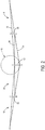
- a space frame 30 is configured to extend spanwise within at least a midspan portion of the interior volumes 14' and 16' of each of the left and right wings 14, 16, respectively.
- the space frame 30 is designed to accommodate all tensile, compression, bending, and torsional loads applied to the wings 14 and 16, during all flight, landing, and ground operations of the aircraft wing.
- the wing supporting space frame 30 includes arrays of such spanwise extending carbon fiber rods.
- the visible carbon fiber rod 32 is the upper leading edge carbon fiber rod 32, and is only representative of a parallel array of carbon fiber rods (as will be further described in reference the chordwise cross-sectional view of the space frame in FIG.
- the array of upper carbon fiber rods 32 et seq. is formed of a plurality of parallel singular carbon fiber rods that extend from the right wing tip A to the left wing tip H, as shown.
- each upper carbon fiber rod 32 may exist as a singular or unitary rod, rather than a connection of a series of such rods, through parallel upper load paths A-C-E-G-H, as depicted in the schematic view.
- a lower carbon fiber rod 34 also representative of a parallel array of carbon fiber rods, extends from the right wing tip A to the left wing tip H; each carbon fiber rod 34 may also exist as a single or unitary carbon fiber rod through lower corresponding parallel load paths A-B-D-F-H for optimized strength.
- the arrays of upper and lower carbon fiber rods 32, 34 are secured together in a manner to be described.
- carbon fiber rods can be advantageous for optimizing load-bearing strength of wing structures. This is because individual carbon fibers within a carbon fiber rod are oriented along the axis of the rod. In a truss-style structure, tensile and compressive loads act only along the axis of each rod, thus in a direction of optimal strength. On the other hand, the carbon fibers contained within composite skins are oriented in a plurality of directions, which comparatively reduces effective strength of skin-based composites.
- the upper carbon fiber rods 32 will be primarily subject to compression loads, while the lower carbon fiber rods 34 will be primarily subject to tensile loads. This is because during flight, the entire weight of the aircraft is borne by the wings, tending to bend them upwardly from tip to tip. The qualifier "primarily” is applied because wing loads vary considerably during flight, and most significantly during moderate to severe turbulence. Conversely, during ground operations, the upper carbon fiber rod 32 may be subject to tensile loads, while the lower carbon fiber rod 34 is subject to compression loads. The reason for the latter is because on the ground the wings do not support the weight of the fuselage, as those skilled in the art will appreciate.
- a reinforcing midspan carbon fiber rod 36 (also representative of a parallel array of rods 36) extends along a load path defined by B-E-F, along with a plurality of chordwise arrays of carbon fiber rods, the latter depicted only as simple vertical wing elements 38 and 40 and vertical fuselage element 42 in the schematic view.
- the reinforcing midspan rods 36 act to transfer massive compressive loads from one wing to the other, entirely eliminating any need to transfer such loads to the fuselage, as commonly done via the noted heavy metal wing box joints formed at the sides of a typical jetliner fuselage.
- chordwise arrays of carbon fiber rods of the space frame 30 are configured to be secured to all spanwise arrays carbon fiber rods.
- the rods including 32 and 34 described above are connected to chordwise rods (described below) by sleeve connectors, to be described.
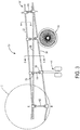
- E-G of the upper spanwise load path A-C-E-G-H ( FIG. 2 ) is shown to provide greater detail of the left interior volume 14', including relative positions of the jet engine 18 and left main landing gear 46 on that particular spanwise subsection of the wing 14.
- a corresponding portion, D-F, of the lower spanwise load path A-B-D-F-H ( FIG. 2 ) is also shown, in reference to the latter aircraft engine and landing gear structures 18 and 46.
- a plurality of sleeve connectors 50 and 52 are utilized to connect adjacent upper and lower spanwise and chordwise, i.e. orthogonally oriented, carbon fiber rods together (see FIG 5 for chordwise view).
- each of the sleeve connectors 50 and 52 is connected to a vertically extending rigid shaft 70.
- the sleeve and shaft fittings 50, 52, and 70 are utilized throughout the space frame 30 to secure the carbon fiber rods together.
- the latter sleeve and shaft fittings 50, 52, and 70 are specific structures within each of the earlier noted chordwise-extending vertical wing and fuselage elements 38, 40, and 42. Ideally, at least two of such chordwise elements within the left and right wings can be positioned to align vertically over the landing gear and engine structures for enhanced strength, as shown in FIG. 3 .
- the sleeve and shaft fittings, further described below, may be secured together by conventionally obtained fasteners and/or other connective structures (not shown).
- a cross-section of the upper spanwise carbon fiber rod 32 ( FIG. 3 ) reveals one embodiment be formed of a sheath or bundle of multiple smaller carbon fiber rods 33, secured together, for example by a composite adhesive 35.
- This embodiment is only one carbon fiber rod of numerous commercially available variants.
- the midspan carbon fiber rods 36 have been removed to better reveal chordwise details of the space frame 30, which includes an array of upper and lower chordwise extending carbon fiber rods 44 and 48, respectively.
- a compound sleeve connector 50 secures the upper spanwise carbon fiber rod 32 to the upper chordwise carbon fiber rod 44.
- a compound sleeve connector 52 secures the lower spanwise carbon fiber rod 34 ( FIG. 3 ) to the lower chordwise carbon fiber rod 48.
- the rigid shaft 70 holds the compound sleeves 50 and 52 together.
- Elongated rigid shafts 72, 72', and 72" which may also be formed of metal, may be angled to extend between the upper and lower compound sleeves 50, 52, as shown. This arrangement constitutes an angled bracing that provides a truss-like framing for overall reinforcement of the space frame 30.
- the sleeve connector 52 utilized to secure orthogonally oriented lower spanwise carbon fiber 34 to lower chordwise carbon fiber 48, is detailed in FIG. 5A .
- the compound connector 52 includes a robust flange aperture separator 60, along with an upper aperture 62 within a barrel 64.
- the sleeve connector 52 also incorporates a lower aperture 66 which extends orthogonally with respect to the upper aperture 62.
- the lower aperture 66 is in a separate lower barrel 68, rigidly and structurally separated by the flange aperture separator 60.
- the compound sleeve connector 50 ( FIG. 5 ) may be identical to the sleeve connector 52.
- an elongated skin panel sleeve connector 56 acts as a fitting for attachment of exterior skin panels 90, 92 ( FIG. 5 ) to the space frame 30.
- a skin support flange 76 is integrally attached to a barrel 80 containing an aperture 78.
- the skin panel 90 ( FIG. 5 ) is installed over a portion of the upper carbon fiber rod 32, adjacent and in between the sleeve connectors 50 and 50', as shown.
- the exterior skin panels 90, 92 may be formed of a laminated composite, or of a conventional aluminum alloy, for example.
- FIG. 5C depicts an angled compound sleeve connector 54 which can be used to secure upper chordwise carbon fiber rods 44 angled with respect to the lower chordwise carbon fiber rods 48 at locations, such as near the trailing edge 24 of the wing 14 ( FIG. 5 ), for example.
- an angled flange aperture separator 60' separates adjacently angled apertures 62' and 66', situated in respective barrels 64' and 68', as shown.
- an array of such chordwise upper and lower carbon fiber rods 44, 44', 44", etc. and 48, 48', 48” etc. would be utilized, similar to earlier described upper and lower spanwise carbon fiber rods 32, 32', 32", etc. and 34, 34', 34", etc., as will be appreciated by those skilled in the art.
- the skin panel 90 may include a honeycomb skin panel reinforcement 94 attached to the interior of the exterior skin panel 90.
- the honeycomb skin panel reinforcement 94 which may, for example, also be formed of a laminated composite or an aluminum alloy, is shown secured by skin panel sleeve connectors 56, extending between upper spanwise carbon fiber rods 32 and 32'.
- Each panel may be secured to the skin support flange 76 of each connector 56 via rivets 100, as depicted.
- the disclosed space frame 30 may provide alternative and less costly approaches to manufacturing aircraft, including a wing-centric approach of building the wings to receive the fuselage rather than vice versa.
- a manufacturing sequence of building an aircraft without necessity of conventional heavy structural metal wing box joints formed at either side of the fuselage for attaching the left and right wings may, for example, involve the steps of:
- the fittings can be integral compound sleeve and shaft connectors for securing above referenced orthogonally adjacent spanwise and chordwise arrays of carbon fiber rods together.
- the fuselage may then be secured to the single piece by commercially available fittings.
- the disclosed embodiment of the space frame 30 may have other variations and alternative constructions neither described nor suggested herein.
- other configurations and/or other components may be utilized, and potentially in other environments.
- the disclosure presents structures in only the shapes and sizes depicted, numerous variations of the disclosed structures may be envisioned for use in alternative embodiments, as may be appreciated by those skilled in the art.
Landscapes
- Engineering & Computer Science (AREA)
- Aviation & Aerospace Engineering (AREA)
- Mechanical Engineering (AREA)
- Manufacturing & Machinery (AREA)
- Transportation (AREA)
- Moulding By Coating Moulds (AREA)
- Laminated Bodies (AREA)
Abstract
Description
- The present disclosure generally relates to aircraft wing support structures, and more specifically to utilization of carbon fiber rods to improve structural strength and reduce weight of aircraft wings for achieving enhanced performance.
- Commercial aircraft wings have traditionally incorporated interior arrays of interconnected metal parts, including spars, ribs and stringers, for meeting varying tensile, compression, bending, and torsional wing-load demands during aircraft flight and landing operations. As newer, lighter, and stronger composite materials have become available for enhancing structural support, additional possibilities exist for building stronger wings for improving performance without weight penalties of traditional metal structures.
- One significant weight-savings potential can result from elimination of traditional wing box joints provided at each side of a commercial jetliner fuselage to enable structural attachment of wings to the fuselage. Wing box joints included on commercial jetliners are formed of heavily reinforced metal structures, even for newer jetliners formed primarily of non-metallic composites, often requiring massive and expensive autoclave assemblies for their manufacture. A wing support space frame formed of carbon fiber rods can provide opportunities for elimination of conventionally designed heavy metal wing box joints, and among other benefits enable avoidance of autoclave use.
- In accordance with one form of the present disclosure, an aircraft wing is configured for securement to a fuselage, the wing including an exterior skin that defines an interior volume. The interior volume incorporates a space frame configured to support all tensile, compression, bending and torsional loads applied to the wing during flight, landing, and ground operations. The space frame is defined by a first array of carbon fiber rods extending spanwise within the interior volume, and a second array of carbon fiber rods extending chordwise within the interior volume. The first and second arrays are secured together by a first plurality of connectors, and the exterior skin is internally secured to the space frame by a second plurality of connectors.
- In accordance with another form of the present disclosure, a space frame is configured to structurally support a pair of integrated left and right aircraft wings having an exterior skin defining their interior volume. The space frame includes a first array of carbon fiber rods configured to extend spanwise within the interior volume at least midspan of each wing, and a second array of carbon fiber rods configured to extend chordwise from a leading edge to a trailing edge within the interior volume of each wing. The first and second arrays are secured together by a first plurality of connectors.
- In accordance with yet another form of the present disclosure, a wing-centric method of manufacturing an aircraft includes steps of forming a unitary space frame to support a pair of integrally connected left and right aircraft wings having an exterior skin defining an interior volume of the wings. A first array of carbon fiber rods are secured to a second array of carbon fiber rods via a plurality of connectors to form the space frame, which is configured to have the first array of carbon fiber rods extend spanwise at least midspan within the interior volume of the wings, and to have the second array of carbon fiber rods extend chordwise from a leading to a trailing edge of the wings. An aircraft fuselage frame is next attached over a central portion of the space frame, and exterior skin panels are applied to the space frame and to the fuselage frame.
- The features, functions, and advantages disclosed herein can be achieved independently in various embodiments or may be combined in yet other embodiments, the details of which may be better appreciated with reference to the following description and drawings.
- Set out below are a series of clauses that disclose features of further aspects of the invention, which may be claimed. The clauses that do not refer to a preceding clause contain essential features of that aspect; the clauses that do refer to one or more preceding clause contain optional features of that aspect.
- Clause 1. A space frame configured to structurally support a pair of integrated left and right aircraft wings that have an exterior skin defining an interior volume of the wings; the space frame comprising:
- a first array of carbon fiber rods configured to extend spanwise within the interior volume at least midspan of each wing, and a second array of carbon fiber rods configured to extend chordwise from a leading edge to a trailing edge within the interior volume; the first and second arrays secured together by a first plurality of connectors.
- Clause 2. The space frame of clause1, wherein the first plurality of connectors comprises sleeve connectors, each sleeve connector coupled to a rigid shaft.
- Clause 3. The space frame of clause 2, wherein the first plurality of connectors is arranged in truss-like configurations with respect to the carbon fiber rods.
- Clause 4. The space frame of clauses1-3, wherein each of the first and second arrays of carbon fiber rods include upper and lower carbon fiber rods secured together by the first plurality of connectors.
-
Clause 5. The space frame of clauses 1-4, wherein the first plurality of connectors include compound sleeve connectors, wherein each compound sleeve connector is configured to tie together an upper carbon fiber rod of the first array to an upper carbon fiber rod of the second array, and to tie together a lower carbon fiber rod of the first array to a lower carbon fiber rod of the second array. - Clause 6. The space frame of clause 1-5, further comprising a second plurality of sleeve connectors, and wherein each of the second plurality of sleeve connectors comprises an elongated sleeve having an elongated skin panel sleeve connector configured to secure a skin panel to the space frame.
- Clause 7. The space frame of clause6, wherein each of the second plurality of sleeve connectors is configured to extend spanwise over the first array of carbon fiber rods.
-
-
FIG. 1 is a perspective view of an aircraft in flight, the aircraft including wings incorporating a space frame, constructed in accordance with the present disclosure. -
FIG. 2 is a schematic frontal view of the aircraft ofFIG. 1 , with its fuselage, exterior wing skin, and engines removed to reveal a wing supporting space frame formed of spanwise extending carbon fiber rods, configured in accordance with the present disclosure. -
FIG. 3 is a schematic portion of the view ofFIG. 2 , to show greater detail of the space frame, constructed in accordance with the present disclosure. -
FIG. 4 is a cross-sectional view, taken along lines 4-4 ofFIG. 3 , of a carbon fiber rod that may be utilized in at least one embodiment of the space frame, constructed in accordance with the present disclosure. -
FIG. 5 is a chordwise cross-sectional view, taken along lines 5-5 ofFIG. 3 , of the space frame as may be configured for a wing of the aircraft ofFIG. 1 , including a perspective view of at least one embodiment of exterior skin panels applied to the space frame, in accordance with the present disclosure. -
FIG. 5A is a perspective view of a compound sleeve component shown inFIG. 5 , that may be utilized to connect orthogonally oriented spanwise and chordwise extending carbon fiber rods of the disclosed space frame. -
FIG. 5B is a perspective view of an elongated compound sleeve and flange component shown inFIG. 5 , that may be utilized to attach skin panels to the disclosed space frame. -
FIG. 5C is a perspective view of a compound sleeve component shown inFIG. 5 , that may be utilized to attach chordwise extending upper and lower carbon fiber rods, such as at the trailing edge of a wing ofFIG. 1 . -
FIG. 6 is a chordwise cross-section view of a skin panel installation situated between an upper pair of spanwise extending carbon fiber rods, revealing details of the elongated compound sleeve and flange component ofFIG. 5B . - It should be understood that referenced drawings are not necessarily to scale, and that disclosed embodiments are illustrated only schematically. Aspects of the disclosed embodiments may be combined with or substituted by one another, and within various systems and environments that are neither shown nor described herein. As such, it should be understood that the following detailed description is merely exemplary, and not intended to be limiting in either application or use.
- The following detailed description addresses both apparatus and methods for carrying out the disclosure. Actual scope of the disclosure is as defined in the appended claims.
- Referring initially to
FIG. 1 , anaircraft 10 is shown in flight. Theaircraft 10 includes a main body orfuselage 12, and a pair of wings including aleft wing 14 and aright wing 16, each wing extending laterally, or outwardly of thefuselage 12, in a so-called spanwise direction. Eachwing left engine 18 and aright engine 20 is supported from each of the left andright wings edge 22 and atrailing edge 24, the latter shown only with respect to theleft wing 14. Theaircraft 10 further includes anose 25, and a tail orempennage 26, which includes avertical stabilizer 28 and left and righthorizontal stabilizers 29. - Referring now to
FIG. 2 , aspace frame 30 is configured to extend spanwise within at least a midspan portion of the interior volumes 14' and 16' of each of the left andright wings space frame 30 is designed to accommodate all tensile, compression, bending, and torsional loads applied to thewings carbon fiber rod 32 is visible inFIG. 2 , the wing supportingspace frame 30 includes arrays of such spanwise extending carbon fiber rods. As such, the visiblecarbon fiber rod 32 is the upper leading edgecarbon fiber rod 32, and is only representative of a parallel array of carbon fiber rods (as will be further described in reference the chordwise cross-sectional view of the space frame inFIG. 5 ). In the example depicted, the array of uppercarbon fiber rods 32 et seq. is formed of a plurality of parallel singular carbon fiber rods that extend from the right wing tip A to the left wing tip H, as shown. For optimized strength, each uppercarbon fiber rod 32 may exist as a singular or unitary rod, rather than a connection of a series of such rods, through parallel upper load paths A-C-E-G-H, as depicted in the schematic view. - Correspondingly, a lower
carbon fiber rod 34, also representative of a parallel array of carbon fiber rods, extends from the right wing tip A to the left wing tip H; eachcarbon fiber rod 34 may also exist as a single or unitary carbon fiber rod through lower corresponding parallel load paths A-B-D-F-H for optimized strength. The arrays of upper and lowercarbon fiber rods - As those skilled in the art will appreciate, the use of carbon fiber rods can be advantageous for optimizing load-bearing strength of wing structures. This is because individual carbon fibers within a carbon fiber rod are oriented along the axis of the rod. In a truss-style structure, tensile and compressive loads act only along the axis of each rod, thus in a direction of optimal strength. On the other hand, the carbon fibers contained within composite skins are oriented in a plurality of directions, which comparatively reduces effective strength of skin-based composites.
- It will be appreciated that during flight the upper
carbon fiber rods 32 will be primarily subject to compression loads, while the lowercarbon fiber rods 34 will be primarily subject to tensile loads. This is because during flight, the entire weight of the aircraft is borne by the wings, tending to bend them upwardly from tip to tip. The qualifier "primarily" is applied because wing loads vary considerably during flight, and most significantly during moderate to severe turbulence. Conversely, during ground operations, the uppercarbon fiber rod 32 may be subject to tensile loads, while the lowercarbon fiber rod 34 is subject to compression loads. The reason for the latter is because on the ground the wings do not support the weight of the fuselage, as those skilled in the art will appreciate. - To assist in managing compression loading of the carbon fiber rods within the
space frame 30, a reinforcing midspan carbon fiber rod 36 (also representative of a parallel array of rods 36) extends along a load path defined by B-E-F, along with a plurality of chordwise arrays of carbon fiber rods, the latter depicted only as simplevertical wing elements vertical fuselage element 42 in the schematic view. The reinforcingmidspan rods 36 act to transfer massive compressive loads from one wing to the other, entirely eliminating any need to transfer such loads to the fuselage, as commonly done via the noted heavy metal wing box joints formed at the sides of a typical jetliner fuselage. As will become more apparent, all chordwise arrays of carbon fiber rods of thespace frame 30 are configured to be secured to all spanwise arrays carbon fiber rods. As such, the rods including 32 and 34 described above are connected to chordwise rods (described below) by sleeve connectors, to be described. - Referring now to
FIG. 3 , only a portion, E-G, of the upper spanwise load path A-C-E-G-H (FIG. 2 ) is shown to provide greater detail of the left interior volume 14', including relative positions of thejet engine 18 and leftmain landing gear 46 on that particular spanwise subsection of thewing 14. A corresponding portion, D-F, of the lower spanwise load path A-B-D-F-H (FIG. 2 ) is also shown, in reference to the latter aircraft engine andlanding gear structures sleeve connectors FIG 5 for chordwise view). As particularly identified above thelanding gear 46, each of thesleeve connectors rigid shaft 70. The sleeve andshaft fittings space frame 30 to secure the carbon fiber rods together. It will be noted that the latter sleeve andshaft fittings fuselage elements FIG. 3 . The sleeve and shaft fittings, further described below, may be secured together by conventionally obtained fasteners and/or other connective structures (not shown). - Referring now also to
FIG. 4 , a cross-section of the upper spanwise carbon fiber rod 32 (FIG. 3 ) reveals one embodiment be formed of a sheath or bundle of multiple smallercarbon fiber rods 33, secured together, for example by acomposite adhesive 35. This embodiment is only one carbon fiber rod of numerous commercially available variants. - In
FIG. 5 , the midspancarbon fiber rods 36 have been removed to better reveal chordwise details of thespace frame 30, which includes an array of upper and lower chordwise extendingcarbon fiber rods compound sleeve connector 50 secures the upper spanwisecarbon fiber rod 32 to the upper chordwisecarbon fiber rod 44. Similarly, acompound sleeve connector 52 secures the lower spanwise carbon fiber rod 34 (FIG. 3 ) to the lower chordwisecarbon fiber rod 48. Therigid shaft 70 holds thecompound sleeves - As will be appreciated, the same connections are replicated chordwise from the leading
edge 22 to the trailingedge 24 of the interior volume 14'. Thus, between theleading edge 22 and the trailingedge 24 are similarcorresponding structures 50', 50" and 50"', along with 52', 52", 52"', and 70', 70", 70"', all configured to secure respective upper spanwisecarbon fiber rods 32', 32", and 32"' to upper chordwisecarbon fiber rods 44, and similar lower spanwise carbon fiber rods (shown only as 34 inFIG. 3 to the lower chordwisecarbon fiber rods 48. - Elongated
rigid shafts lower compound sleeves space frame 30. - Referring now also to
FIGS. 5A, 5B, and 5C , it will be noted that alternative compound sleeve connector structures can be employed to secure the carbon fiber rods together in the manner described. Thus, thesleeve connector 52, utilized to secure orthogonally oriented lowerspanwise carbon fiber 34 to lowerchordwise carbon fiber 48, is detailed inFIG. 5A . Thecompound connector 52 includes a robustflange aperture separator 60, along with anupper aperture 62 within abarrel 64. Thesleeve connector 52 also incorporates alower aperture 66 which extends orthogonally with respect to theupper aperture 62. Thelower aperture 66 is in a separatelower barrel 68, rigidly and structurally separated by theflange aperture separator 60. In the disclosed embodiment, the compound sleeve connector 50 (FIG. 5 ) may be identical to thesleeve connector 52. - In
FIG. 5B , an elongated skinpanel sleeve connector 56 acts as a fitting for attachment ofexterior skin panels 90, 92 (FIG. 5 ) to thespace frame 30. Askin support flange 76 is integrally attached to abarrel 80 containing anaperture 78. Thus, the skin panel 90 (FIG. 5 ) is installed over a portion of the uppercarbon fiber rod 32, adjacent and in between thesleeve connectors 50 and 50', as shown. Theexterior skin panels -
FIG. 5C depicts an angledcompound sleeve connector 54 which can be used to secure upper chordwisecarbon fiber rods 44 angled with respect to the lower chordwisecarbon fiber rods 48 at locations, such as near the trailingedge 24 of the wing 14 (FIG. 5 ), for example. For this purpose, an angled flange aperture separator 60' separates adjacently angled apertures 62' and 66', situated in respective barrels 64' and 68', as shown. Obviously, an array of such chordwise upper and lowercarbon fiber rods carbon fiber rods - Referring now also to
FIG. 6 , additional details of theskin panel 90 may include a honeycombskin panel reinforcement 94 attached to the interior of theexterior skin panel 90. The honeycombskin panel reinforcement 94, which may, for example, also be formed of a laminated composite or an aluminum alloy, is shown secured by skinpanel sleeve connectors 56, extending between upper spanwisecarbon fiber rods 32 and 32'. Each panel may be secured to theskin support flange 76 of eachconnector 56 viarivets 100, as depicted. - Finally, the disclosed
space frame 30 may provide alternative and less costly approaches to manufacturing aircraft, including a wing-centric approach of building the wings to receive the fuselage rather than vice versa. Thus, a manufacturing sequence of building an aircraft without necessity of conventional heavy structural metal wing box joints formed at either side of the fuselage for attaching the left and right wings may, for example, involve the steps of: - a) forming a unitary space frame to support a pair of integrated left and right aircraft wings having an exterior skin defining an interior volume of the wings, by securing a first array of carbon fiber rods to a second array of carbon fiber rods via a plurality of sleeve connectors;
- b) configuring the space frame to have the first array of carbon fiber rods extend spanwise within the interior volume at least midspan of each wing, and to have the second array of carbon fiber rods extend chordwise from a leading edge to a trailing edge of the wings;
- c) attaching an aircraft fuselage frame over a central portion of the space frame; and
- d) applying skin panels to the space frame and to the fuselage frame.
- In a wing-centric manufacturing approach, the fittings can be integral compound sleeve and shaft connectors for securing above referenced orthogonally adjacent spanwise and chordwise arrays of carbon fiber rods together. The fuselage may then be secured to the single piece by commercially available fittings.
- The disclosed embodiment of the
space frame 30 may have other variations and alternative constructions neither described nor suggested herein. For example, although described in terms of specific structures and components, other configurations and/or other components may be utilized, and potentially in other environments. Moreover, although the disclosure presents structures in only the shapes and sizes depicted, numerous variations of the disclosed structures may be envisioned for use in alternative embodiments, as may be appreciated by those skilled in the art. - Features of each embodiments may be combined with one or more embodiments from elsewhere in the disclosure in any suitable manner.
Claims (13)
- An aircraft wing configured for securement to a fuselage; the wing comprising:an exterior skin defining an interior volume;the interior volume having a space frame configured to support all tensile, compression, bending and torsional loads applied to the wing during flight, landing, and ground operations of the aircraft wing;wherein the space frame is defined by a first array of carbon fiber rods extending spanwise within the interior volume, and a second array of carbon fiber rods extending chordwise within the interior volume; the first and second arrays secured together by a first plurality of connectors, andwherein the exterior skin is secured to the space frame by a second plurality of connectors.
- The aircraft wing of claim 1, wherein the space frame comprises a primary supporting structure of the wing, and wherein the exterior skin is configured to support only aerodynamic loads.
- The aircraft wing of claims 1-2, wherein the first plurality of connectors comprises sleeve connectors secured to the carbon fiber rods, each sleeve connector coupled to a rigid shaft to prevent buckling of the carbon fiber rods when subject to compressive loads.
- The aircraft wing of claim 3, wherein the sleeve connectors are arranged in truss-like configurations with respect to the carbon fiber rods.
- The aircraft wing of claims 1-4, comprising an integrated system of left and right wings, wherein the space frame comprises at least a midspan portion of the interior volume of both left and right wings.
- The aircraft wing of claim 5, wherein the space frame extends spanwise at least midspan of the interior volume of each wing.
- The aircraft wing of claims 5-6, wherein the space frame comprises upper spanwise carbon fiber rods in a state of compression when the wing is in flight, and in a state of tension when the wing is not in flight.
- The aircraft wing of claims 5-7, wherein the space frame comprises lower spanwise carbon fiber rods in a state of tension when the wing is in flight, and in a state of compression when the wing is not in flight.
- The aircraft wing of claim 8, wherein the space frame further comprises an array of separate reinforcing midspan carbon fiber rods, each reinforcing midspan carbon fiber rod configured to reciprocally transfer compressive loads between the left and right wings.
- The aircraft wing of claim 9, wherein each reinforcing midspan carbon fiber rod structurally links an upper spanwise carbon fiber rod with a lower spanwise carbon fiber rod.
- A method of manufacturing an aircraft; the method comprising steps of:forming a unitary space frame to support a pair of integrated left and right wings having an exterior skin defining an interior volume of the wings, by securing a first array of carbon fiber rods to a second array of carbon fiber rods via a plurality of connectors;configuring the space frame to have the first array of carbon fiber rods extend spanwise within the interior volume at least midspan of each wing, and to have the second array of carbon fiber rods extend chordwise from a leading edge to a trailing edge of the wings;attaching an aircraft fuselage frame over a central portion of the space frame; andapplying skin panels to the space frame and to the fuselage frame.
- The method of claim 11, wherein the connectors comprise sleeve and shaft connectors.
- The method of claim 12, wherein the sleeve connectors comprise compound sleeve connectors for securing orthogonally oriented adjacent carbon fiber rods together.
Applications Claiming Priority (1)
| Application Number | Priority Date | Filing Date | Title |
|---|---|---|---|
| US15/468,866 US10850826B2 (en) | 2017-03-24 | 2017-03-24 | Aircraft wing space frame |
Publications (1)
| Publication Number | Publication Date |
|---|---|
| EP3378758A1 true EP3378758A1 (en) | 2018-09-26 |
Family
ID=61132338
Family Applications (1)
| Application Number | Title | Priority Date | Filing Date |
|---|---|---|---|
| EP18154753.0A Ceased EP3378758A1 (en) | 2017-03-24 | 2018-02-01 | Aircraft wing space frame |
Country Status (3)
| Country | Link |
|---|---|
| US (1) | US10850826B2 (en) |
| EP (1) | EP3378758A1 (en) |
| CN (1) | CN108622368B (en) |
Families Citing this family (8)
| Publication number | Priority date | Publication date | Assignee | Title |
|---|---|---|---|---|
| US20200122816A1 (en) * | 2018-10-22 | 2020-04-23 | The Boeing Company | Bulkhead joint assembly |
| EP4100319B1 (en) * | 2020-02-06 | 2025-11-19 | AeroVironment, Inc. | D-truss wing structure for an unmanned aerial vehicle |
| CN113443121A (en) * | 2020-03-24 | 2021-09-28 | 西北工业大学 | Unmanned aerial vehicle and wing thereof |
| US11845566B2 (en) * | 2020-11-18 | 2023-12-19 | The Boeing Company | Frame fabrication line |
| US11597490B1 (en) | 2021-12-22 | 2023-03-07 | Rapidflight Holdings, Llc | Additive manufactured airframe structure having a plurality of reinforcement elements |
| US20240166330A1 (en) * | 2022-11-21 | 2024-05-23 | Rapidflight Holdings Llc | Additive manufactured wing structure having a plurality of chordwise wing segments |
| EP4600140A1 (en) * | 2024-02-07 | 2025-08-13 | BAE SYSTEMS plc | Structural assemblies for aircraft |
| WO2025168918A1 (en) * | 2024-02-07 | 2025-08-14 | Bae Systems Plc | Structural assemblies for aircraft |
Citations (7)
| Publication number | Priority date | Publication date | Assignee | Title |
|---|---|---|---|---|
| FR673934A (en) * | 1928-04-25 | 1930-01-21 | Emboutissage Et De Const Mecan | Improvements made to reinforcements for aircraft bearing surfaces, in particular those for airplane wings |
| DE102005038849A1 (en) * | 2005-08-17 | 2007-02-22 | Airbus Deutschland Gmbh | Support structure for a wing |
| US20080245927A1 (en) * | 2007-04-05 | 2008-10-09 | Kulesha Richard L | Methods and systems for composite structural truss |
| US20150151830A1 (en) * | 2012-06-21 | 2015-06-04 | Bombardier Inc. | Morphing wing for an aircraft |
| US20150167288A1 (en) * | 2012-07-06 | 2015-06-18 | Paul Harkin | Adjustable Structures |
| EP2947009A1 (en) * | 2014-05-20 | 2015-11-25 | The Boeing Company | Solar powered airplane |
| US20150369212A1 (en) * | 2008-12-05 | 2015-12-24 | Vestas Wind Systems A/S | Efficient wind turbine blades, wind turbine blade structures, and associated systems and methods of manufacture, assembly and use |
Family Cites Families (26)
| Publication number | Priority date | Publication date | Assignee | Title |
|---|---|---|---|---|
| US1325499A (en) | 1919-12-16 | Wings and the like | ||
| US1291678A (en) | 1916-03-31 | 1919-01-14 | Curtiss Aeroplane & Motor Co | Wing construction. |
| US1403444A (en) | 1917-12-31 | 1922-01-10 | Rapp | Airplane-wing construction |
| US1328963A (en) * | 1919-09-06 | 1920-01-27 | Handley Page Ltd | Connection for members of aircraft-frames |
| US1555409A (en) * | 1920-12-27 | 1925-09-29 | Curtiss Aeroplane & Motor Co | Airplane wing |
| US1545129A (en) * | 1923-09-27 | 1925-07-07 | Jr John F Cook | Aircraft structure |
| US2791386A (en) * | 1953-10-19 | 1957-05-07 | Lockheed Aircraft Corp | Truss core |
| GB9024387D0 (en) * | 1990-11-09 | 1991-01-02 | British Aerospace | Carbon fibre composite wing manufacture |
| US7037568B1 (en) * | 2003-07-15 | 2006-05-02 | Rogers Terry W | Joining member for mechanically joining a skin to a supporting rib |
| DE102005038851A1 (en) * | 2005-08-17 | 2007-03-01 | Airbus Deutschland Gmbh | Wing box for aircraft wing, has framework connected to at least one exterior shell such that load acting on exterior shell is transferred by framework |
| US7517198B2 (en) | 2006-03-20 | 2009-04-14 | Modular Wind Energy, Inc. | Lightweight composite truss wind turbine blade |
| GR1006556B (en) * | 2007-04-04 | 2009-10-02 | Variable and fixed joints-nodes with an incorporated two-part mechanical joint for lateral connection between tubes, beams and rods for the construction of framework. | |
| DE102007019692B4 (en) * | 2007-04-26 | 2011-06-01 | Airbus Operations Gmbh | Wing-hull section of an airplane |
| US20090224102A1 (en) * | 2008-03-06 | 2009-09-10 | White Walter W | Aircraft Wing and Fuselage Structure |
| EP2530010B1 (en) * | 2011-06-02 | 2013-09-18 | Bell Helicopter Textron Inc. | Integrally stiffened panel |
| US9010688B2 (en) * | 2012-02-07 | 2015-04-21 | The Boeing Company | Structural joint having continuous skin with inside and outside stringers |
| AU2012244116B1 (en) * | 2012-07-04 | 2013-03-21 | Systems Pty Ltd | Building system and panel for a building system |
| EP2716544B1 (en) * | 2012-10-03 | 2020-04-08 | Airbus Operations S.L. | Horizontal airfoil tip fairing |
| US9096324B2 (en) | 2013-03-19 | 2015-08-04 | The Boeing Company | Joint assembly to form a sealed flow conduit |
| CN103171756B (en) * | 2013-03-19 | 2014-12-10 | 北京航空航天大学 | Wing rib-free rapid water injection and drainage wing suitable for sea and air across amphibious unmanned aerial vehicle |
| US9156538B1 (en) * | 2013-07-22 | 2015-10-13 | The Boeing Company | Aircraft skin attachment system |
| EP2921600B1 (en) * | 2014-03-19 | 2016-05-18 | Airbus Operations GmbH | Rotary joint, framework construction kit and method for constructing a framework |
| FR3021898B1 (en) * | 2014-06-10 | 2016-07-15 | Daher Aerospace | METHOD FOR ASSEMBLING A SET OF COMPOSITE PARTS AND ASSEMBLY OBTAINED BY SUCH A METHOD |
| US10040537B2 (en) * | 2015-01-15 | 2018-08-07 | The Boeing Company | Laminate composite wing structures |
| US10358821B2 (en) * | 2015-03-02 | 2019-07-23 | The Boeing Company | Thermoplastic truss structure for use in wing and rotor blade structures and methods for manufacture |
| US10207789B2 (en) * | 2016-08-16 | 2019-02-19 | The Boeing Company | Aircraft composite wingbox integration |
-
2017
- 2017-03-24 US US15/468,866 patent/US10850826B2/en active Active
-
2018
- 2018-01-23 CN CN201810065647.0A patent/CN108622368B/en active Active
- 2018-02-01 EP EP18154753.0A patent/EP3378758A1/en not_active Ceased
Patent Citations (7)
| Publication number | Priority date | Publication date | Assignee | Title |
|---|---|---|---|---|
| FR673934A (en) * | 1928-04-25 | 1930-01-21 | Emboutissage Et De Const Mecan | Improvements made to reinforcements for aircraft bearing surfaces, in particular those for airplane wings |
| DE102005038849A1 (en) * | 2005-08-17 | 2007-02-22 | Airbus Deutschland Gmbh | Support structure for a wing |
| US20080245927A1 (en) * | 2007-04-05 | 2008-10-09 | Kulesha Richard L | Methods and systems for composite structural truss |
| US20150369212A1 (en) * | 2008-12-05 | 2015-12-24 | Vestas Wind Systems A/S | Efficient wind turbine blades, wind turbine blade structures, and associated systems and methods of manufacture, assembly and use |
| US20150151830A1 (en) * | 2012-06-21 | 2015-06-04 | Bombardier Inc. | Morphing wing for an aircraft |
| US20150167288A1 (en) * | 2012-07-06 | 2015-06-18 | Paul Harkin | Adjustable Structures |
| EP2947009A1 (en) * | 2014-05-20 | 2015-11-25 | The Boeing Company | Solar powered airplane |
Also Published As
| Publication number | Publication date |
|---|---|
| US10850826B2 (en) | 2020-12-01 |
| CN108622368A (en) | 2018-10-09 |
| US20180273159A1 (en) | 2018-09-27 |
| CN108622368B (en) | 2022-12-13 |
Similar Documents
| Publication | Publication Date | Title |
|---|---|---|
| US10850826B2 (en) | Aircraft wing space frame | |
| US7887009B2 (en) | Methods and systems for attaching aircraft wings to fuselages | |
| US9580164B2 (en) | Apparatus and methods for joining aircraft composite structures | |
| CN110573421B (en) | Assembly for an aircraft comprising a primary structure of an attachment pylon attached to a wing box using bolted connections | |
| CN106335629B (en) | Fuselage spar structure with continuous integral fastened upper and lower chord sections | |
| US8322656B2 (en) | Wing-fuselage section of an aircraft | |
| US9688382B2 (en) | Method of constructing a fixed-wing aircraft | |
| EP2772427B1 (en) | Vertically integrated stringers | |
| US8695922B2 (en) | Aircraft fuselage structure and method for its production | |
| EP2810869B1 (en) | Lower joints between outboard wing boxes and center wing sections of aircraft wing assemblies | |
| JP6930876B2 (en) | Aircraft wing and aircraft including the aircraft wing | |
| CN104097764B (en) | The spar and its manufacturing method of continuous bend | |
| EP3075653B1 (en) | Composite rib for an aircraft | |
| EP2173615A2 (en) | Stiffened multispar torsion box | |
| EP3653490B1 (en) | Frame assembly for a rear section of an aircraft and rear section of an aircraft comprising said frame assembly | |
| EP3415414B1 (en) | Wing-to-fuselage joints and aircraft including the same | |
| US20170066518A1 (en) | Aircraft rear portion comprising a vertical stabilizer having a box-section structure including a lower portion accommodated in the fuselage | |
| EP2886449A1 (en) | Leading edge for an aircraft lifting surface | |
| EP3501971B1 (en) | Aircraft rear fuselage section and manufacturing method thereof | |
| EP4129818B1 (en) | An aircraft or spacecraft fuselage with a structural junction | |
| CN102849218A (en) | Mounting beam for auxiliary power unit of aircraft | |
| EP3805092B1 (en) | Fuselage sections having tapered wing rib interfaces | |
| CN219487711U (en) | Lightweight aircraft body structure | |
| CN222408563U (en) | Wing and aircraft | |
| EP4365083B1 (en) | SYSTEMS AND METHOD FOR COUPLING A STRUT TO A WING OF AN AIRCRAFT |
Legal Events
| Date | Code | Title | Description |
|---|---|---|---|
| PUAI | Public reference made under article 153(3) epc to a published international application that has entered the european phase |
Free format text: ORIGINAL CODE: 0009012 |
|
| STAA | Information on the status of an ep patent application or granted ep patent |
Free format text: STATUS: REQUEST FOR EXAMINATION WAS MADE |
|
| 17P | Request for examination filed |
Effective date: 20180201 |
|
| AK | Designated contracting states |
Kind code of ref document: A1 Designated state(s): AL AT BE BG CH CY CZ DE DK EE ES FI FR GB GR HR HU IE IS IT LI LT LU LV MC MK MT NL NO PL PT RO RS SE SI SK SM TR |
|
| AX | Request for extension of the european patent |
Extension state: BA ME |
|
| STAA | Information on the status of an ep patent application or granted ep patent |
Free format text: STATUS: EXAMINATION IS IN PROGRESS |
|
| 17Q | First examination report despatched |
Effective date: 20200312 |
|
| STAA | Information on the status of an ep patent application or granted ep patent |
Free format text: STATUS: THE APPLICATION HAS BEEN REFUSED |
|
| 18R | Application refused |
Effective date: 20210910 |