EP3378749A1 - Leaning vehicle - Google Patents
Leaning vehicle Download PDFInfo
- Publication number
- EP3378749A1 EP3378749A1 EP16866353.2A EP16866353A EP3378749A1 EP 3378749 A1 EP3378749 A1 EP 3378749A1 EP 16866353 A EP16866353 A EP 16866353A EP 3378749 A1 EP3378749 A1 EP 3378749A1
- Authority
- EP
- European Patent Office
- Prior art keywords
- body frame
- vehicle
- roll angle
- leaning vehicle
- control
- Prior art date
- Legal status (The legal status is an assumption and is not a legal conclusion. Google has not performed a legal analysis and makes no representation as to the accuracy of the status listed.)
- Granted
Links
- 230000007246 mechanism Effects 0.000 claims abstract description 221
- 230000008859 change Effects 0.000 claims abstract description 42
- 238000012546 transfer Methods 0.000 claims description 53
- 239000000725 suspension Substances 0.000 description 157
- 230000001629 suppression Effects 0.000 description 75
- 230000008602 contraction Effects 0.000 description 70
- 239000000872 buffer Substances 0.000 description 57
- 230000033001 locomotion Effects 0.000 description 50
- 230000002265 prevention Effects 0.000 description 29
- 238000000034 method Methods 0.000 description 22
- 230000008569 process Effects 0.000 description 17
- 238000013459 approach Methods 0.000 description 14
- 230000035939 shock Effects 0.000 description 13
- 230000001105 regulatory effect Effects 0.000 description 11
- 230000001276 controlling effect Effects 0.000 description 10
- 230000001133 acceleration Effects 0.000 description 7
- 230000005540 biological transmission Effects 0.000 description 3
- 239000003638 chemical reducing agent Substances 0.000 description 3
- 230000007423 decrease Effects 0.000 description 3
- 230000005484 gravity Effects 0.000 description 3
- 238000010586 diagram Methods 0.000 description 2
- 230000006870 function Effects 0.000 description 2
- 230000004043 responsiveness Effects 0.000 description 2
- 230000006399 behavior Effects 0.000 description 1
- 238000013016 damping Methods 0.000 description 1
- 238000012217 deletion Methods 0.000 description 1
- 230000037430 deletion Effects 0.000 description 1
- 230000000694 effects Effects 0.000 description 1
- 239000011553 magnetic fluid Substances 0.000 description 1
- 238000012986 modification Methods 0.000 description 1
- 230000004048 modification Effects 0.000 description 1
- 238000012544 monitoring process Methods 0.000 description 1
- 230000004044 response Effects 0.000 description 1
Images


Classifications
-
- B—PERFORMING OPERATIONS; TRANSPORTING
- B62—LAND VEHICLES FOR TRAVELLING OTHERWISE THAN ON RAILS
- B62K—CYCLES; CYCLE FRAMES; CYCLE STEERING DEVICES; RIDER-OPERATED TERMINAL CONTROLS SPECIALLY ADAPTED FOR CYCLES; CYCLE AXLE SUSPENSIONS; CYCLE SIDE-CARS, FORECARS, OR THE LIKE
- B62K5/00—Cycles with handlebars, equipped with three or more main road wheels
- B62K5/10—Cycles with handlebars, equipped with three or more main road wheels with means for inwardly inclining the vehicle body on bends
-
- B—PERFORMING OPERATIONS; TRANSPORTING
- B60—VEHICLES IN GENERAL
- B60G—VEHICLE SUSPENSION ARRANGEMENTS
- B60G17/00—Resilient suspensions having means for adjusting the spring or vibration-damper characteristics, for regulating the distance between a supporting surface and a sprung part of vehicle or for locking suspension during use to meet varying vehicular or surface conditions, e.g. due to speed or load
- B60G17/015—Resilient suspensions having means for adjusting the spring or vibration-damper characteristics, for regulating the distance between a supporting surface and a sprung part of vehicle or for locking suspension during use to meet varying vehicular or surface conditions, e.g. due to speed or load the regulating means comprising electric or electronic elements
- B60G17/016—Resilient suspensions having means for adjusting the spring or vibration-damper characteristics, for regulating the distance between a supporting surface and a sprung part of vehicle or for locking suspension during use to meet varying vehicular or surface conditions, e.g. due to speed or load the regulating means comprising electric or electronic elements characterised by their responsiveness, when the vehicle is travelling, to specific motion, a specific condition, or driver input
- B60G17/0162—Resilient suspensions having means for adjusting the spring or vibration-damper characteristics, for regulating the distance between a supporting surface and a sprung part of vehicle or for locking suspension during use to meet varying vehicular or surface conditions, e.g. due to speed or load the regulating means comprising electric or electronic elements characterised by their responsiveness, when the vehicle is travelling, to specific motion, a specific condition, or driver input mainly during a motion involving steering operation, e.g. cornering, overtaking
-
- B—PERFORMING OPERATIONS; TRANSPORTING
- B60—VEHICLES IN GENERAL
- B60G—VEHICLE SUSPENSION ARRANGEMENTS
- B60G17/00—Resilient suspensions having means for adjusting the spring or vibration-damper characteristics, for regulating the distance between a supporting surface and a sprung part of vehicle or for locking suspension during use to meet varying vehicular or surface conditions, e.g. due to speed or load
- B60G17/015—Resilient suspensions having means for adjusting the spring or vibration-damper characteristics, for regulating the distance between a supporting surface and a sprung part of vehicle or for locking suspension during use to meet varying vehicular or surface conditions, e.g. due to speed or load the regulating means comprising electric or electronic elements
- B60G17/018—Resilient suspensions having means for adjusting the spring or vibration-damper characteristics, for regulating the distance between a supporting surface and a sprung part of vehicle or for locking suspension during use to meet varying vehicular or surface conditions, e.g. due to speed or load the regulating means comprising electric or electronic elements characterised by the use of a specific signal treatment or control method
-
- B—PERFORMING OPERATIONS; TRANSPORTING
- B60—VEHICLES IN GENERAL
- B60G—VEHICLE SUSPENSION ARRANGEMENTS
- B60G21/00—Interconnection systems for two or more resiliently-suspended wheels, e.g. for stabilising a vehicle body with respect to acceleration, deceleration or centrifugal forces
- B60G21/02—Interconnection systems for two or more resiliently-suspended wheels, e.g. for stabilising a vehicle body with respect to acceleration, deceleration or centrifugal forces permanently interconnected
- B60G21/04—Interconnection systems for two or more resiliently-suspended wheels, e.g. for stabilising a vehicle body with respect to acceleration, deceleration or centrifugal forces permanently interconnected mechanically
- B60G21/05—Interconnection systems for two or more resiliently-suspended wheels, e.g. for stabilising a vehicle body with respect to acceleration, deceleration or centrifugal forces permanently interconnected mechanically between wheels on the same axle but on different sides of the vehicle, i.e. the left and right wheel suspensions being interconnected
-
- B—PERFORMING OPERATIONS; TRANSPORTING
- B62—LAND VEHICLES FOR TRAVELLING OTHERWISE THAN ON RAILS
- B62K—CYCLES; CYCLE FRAMES; CYCLE STEERING DEVICES; RIDER-OPERATED TERMINAL CONTROLS SPECIALLY ADAPTED FOR CYCLES; CYCLE AXLE SUSPENSIONS; CYCLE SIDE-CARS, FORECARS, OR THE LIKE
- B62K5/00—Cycles with handlebars, equipped with three or more main road wheels
- B62K5/02—Tricycles
- B62K5/027—Motorcycles with three wheels
-
- B—PERFORMING OPERATIONS; TRANSPORTING
- B62—LAND VEHICLES FOR TRAVELLING OTHERWISE THAN ON RAILS
- B62K—CYCLES; CYCLE FRAMES; CYCLE STEERING DEVICES; RIDER-OPERATED TERMINAL CONTROLS SPECIALLY ADAPTED FOR CYCLES; CYCLE AXLE SUSPENSIONS; CYCLE SIDE-CARS, FORECARS, OR THE LIKE
- B62K5/00—Cycles with handlebars, equipped with three or more main road wheels
- B62K5/02—Tricycles
- B62K5/05—Tricycles characterised by a single rear wheel
-
- B—PERFORMING OPERATIONS; TRANSPORTING
- B62—LAND VEHICLES FOR TRAVELLING OTHERWISE THAN ON RAILS
- B62K—CYCLES; CYCLE FRAMES; CYCLE STEERING DEVICES; RIDER-OPERATED TERMINAL CONTROLS SPECIALLY ADAPTED FOR CYCLES; CYCLE AXLE SUSPENSIONS; CYCLE SIDE-CARS, FORECARS, OR THE LIKE
- B62K5/00—Cycles with handlebars, equipped with three or more main road wheels
- B62K5/08—Cycles with handlebars, equipped with three or more main road wheels with steering devices acting on two or more wheels
-
- B—PERFORMING OPERATIONS; TRANSPORTING
- B60—VEHICLES IN GENERAL
- B60G—VEHICLE SUSPENSION ARRANGEMENTS
- B60G2202/00—Indexing codes relating to the type of spring, damper or actuator
- B60G2202/40—Type of actuator
- B60G2202/442—Rotary actuator
-
- B—PERFORMING OPERATIONS; TRANSPORTING
- B60—VEHICLES IN GENERAL
- B60G—VEHICLE SUSPENSION ARRANGEMENTS
- B60G2204/00—Indexing codes related to suspensions per se or to auxiliary parts
- B60G2204/40—Auxiliary suspension parts; Adjustment of suspensions
- B60G2204/421—Pivoted lever mechanisms for mounting suspension elements, e.g. Watt linkage
-
- B—PERFORMING OPERATIONS; TRANSPORTING
- B60—VEHICLES IN GENERAL
- B60G—VEHICLE SUSPENSION ARRANGEMENTS
- B60G2204/00—Indexing codes related to suspensions per se or to auxiliary parts
- B60G2204/40—Auxiliary suspension parts; Adjustment of suspensions
- B60G2204/423—Rails, tubes, or the like, for guiding the movement of suspension elements
- B60G2204/4232—Sliding mounts
-
- B—PERFORMING OPERATIONS; TRANSPORTING
- B60—VEHICLES IN GENERAL
- B60G—VEHICLE SUSPENSION ARRANGEMENTS
- B60G2300/00—Indexing codes relating to the type of vehicle
- B60G2300/12—Cycles; Motorcycles
- B60G2300/122—Trikes
-
- B—PERFORMING OPERATIONS; TRANSPORTING
- B60—VEHICLES IN GENERAL
- B60G—VEHICLE SUSPENSION ARRANGEMENTS
- B60G2300/00—Indexing codes relating to the type of vehicle
- B60G2300/45—Rolling frame vehicles
-
- B—PERFORMING OPERATIONS; TRANSPORTING
- B60—VEHICLES IN GENERAL
- B60G—VEHICLE SUSPENSION ARRANGEMENTS
- B60G2400/00—Indexing codes relating to detected, measured or calculated conditions or factors
- B60G2400/05—Attitude
- B60G2400/051—Angle
- B60G2400/0511—Roll angle
-
- B—PERFORMING OPERATIONS; TRANSPORTING
- B60—VEHICLES IN GENERAL
- B60G—VEHICLE SUSPENSION ARRANGEMENTS
- B60G2400/00—Indexing codes relating to detected, measured or calculated conditions or factors
- B60G2400/05—Attitude
- B60G2400/051—Angle
- B60G2400/0516—Angular position of a suspension element
- B60G2400/05162—Angular position of a suspension element the element being a suspension arm
-
- B—PERFORMING OPERATIONS; TRANSPORTING
- B60—VEHICLES IN GENERAL
- B60G—VEHICLE SUSPENSION ARRANGEMENTS
- B60G2400/00—Indexing codes relating to detected, measured or calculated conditions or factors
- B60G2400/20—Speed
- B60G2400/204—Vehicle speed
-
- B—PERFORMING OPERATIONS; TRANSPORTING
- B60—VEHICLES IN GENERAL
- B60G—VEHICLE SUSPENSION ARRANGEMENTS
- B60G2400/00—Indexing codes relating to detected, measured or calculated conditions or factors
- B60G2400/30—Propulsion unit conditions
- B60G2400/33—Throttle position
-
- B—PERFORMING OPERATIONS; TRANSPORTING
- B60—VEHICLES IN GENERAL
- B60G—VEHICLE SUSPENSION ARRANGEMENTS
- B60G2400/00—Indexing codes relating to detected, measured or calculated conditions or factors
- B60G2400/40—Steering conditions
- B60G2400/41—Steering angle
-
- B—PERFORMING OPERATIONS; TRANSPORTING
- B60—VEHICLES IN GENERAL
- B60G—VEHICLE SUSPENSION ARRANGEMENTS
- B60G2400/00—Indexing codes relating to detected, measured or calculated conditions or factors
- B60G2400/40—Steering conditions
- B60G2400/42—Steering torque
-
- B—PERFORMING OPERATIONS; TRANSPORTING
- B60—VEHICLES IN GENERAL
- B60G—VEHICLE SUSPENSION ARRANGEMENTS
- B60G2400/00—Indexing codes relating to detected, measured or calculated conditions or factors
- B60G2400/90—Other conditions or factors
- B60G2400/98—Stabiliser movement
-
- B—PERFORMING OPERATIONS; TRANSPORTING
- B60—VEHICLES IN GENERAL
- B60G—VEHICLE SUSPENSION ARRANGEMENTS
- B60G2401/00—Indexing codes relating to the type of sensors based on the principle of their operation
- B60G2401/90—Single sensor for two or more measurements
- B60G2401/904—Single sensor for two or more measurements the sensor being an xyz axis sensor
-
- B—PERFORMING OPERATIONS; TRANSPORTING
- B60—VEHICLES IN GENERAL
- B60G—VEHICLE SUSPENSION ARRANGEMENTS
- B60G2600/00—Indexing codes relating to particular elements, systems or processes used on suspension systems or suspension control systems
- B60G2600/02—Retarders, delaying means, dead zones, threshold values, cut-off frequency, timer interruption
-
- B—PERFORMING OPERATIONS; TRANSPORTING
- B60—VEHICLES IN GENERAL
- B60G—VEHICLE SUSPENSION ARRANGEMENTS
- B60G2600/00—Indexing codes relating to particular elements, systems or processes used on suspension systems or suspension control systems
- B60G2600/07—Inhibiting means
-
- B—PERFORMING OPERATIONS; TRANSPORTING
- B60—VEHICLES IN GENERAL
- B60G—VEHICLE SUSPENSION ARRANGEMENTS
- B60G2600/00—Indexing codes relating to particular elements, systems or processes used on suspension systems or suspension control systems
- B60G2600/18—Automatic control means
- B60G2600/182—Active control means
-
- B—PERFORMING OPERATIONS; TRANSPORTING
- B60—VEHICLES IN GENERAL
- B60G—VEHICLE SUSPENSION ARRANGEMENTS
- B60G2800/00—Indexing codes relating to the type of movement or to the condition of the vehicle and to the end result to be achieved by the control action
- B60G2800/01—Attitude or posture control
- B60G2800/012—Rolling condition
-
- B—PERFORMING OPERATIONS; TRANSPORTING
- B60—VEHICLES IN GENERAL
- B60G—VEHICLE SUSPENSION ARRANGEMENTS
- B60G2800/00—Indexing codes relating to the type of movement or to the condition of the vehicle and to the end result to be achieved by the control action
- B60G2800/18—Starting, accelerating
-
- B—PERFORMING OPERATIONS; TRANSPORTING
- B60—VEHICLES IN GENERAL
- B60G—VEHICLE SUSPENSION ARRANGEMENTS
- B60G2800/00—Indexing codes relating to the type of movement or to the condition of the vehicle and to the end result to be achieved by the control action
- B60G2800/22—Braking, stopping
-
- B—PERFORMING OPERATIONS; TRANSPORTING
- B62—LAND VEHICLES FOR TRAVELLING OTHERWISE THAN ON RAILS
- B62K—CYCLES; CYCLE FRAMES; CYCLE STEERING DEVICES; RIDER-OPERATED TERMINAL CONTROLS SPECIALLY ADAPTED FOR CYCLES; CYCLE AXLE SUSPENSIONS; CYCLE SIDE-CARS, FORECARS, OR THE LIKE
- B62K5/00—Cycles with handlebars, equipped with three or more main road wheels
- B62K2005/001—Suspension details for cycles with three or more main road wheels
-
- B—PERFORMING OPERATIONS; TRANSPORTING
- B62—LAND VEHICLES FOR TRAVELLING OTHERWISE THAN ON RAILS
- B62K—CYCLES; CYCLE FRAMES; CYCLE STEERING DEVICES; RIDER-OPERATED TERMINAL CONTROLS SPECIALLY ADAPTED FOR CYCLES; CYCLE AXLE SUSPENSIONS; CYCLE SIDE-CARS, FORECARS, OR THE LIKE
- B62K21/00—Steering devices
Definitions
- the present teaching relates to a technique for controlling a tilt angle of a leaning vehicle in a left direction of a body frame or in a right direction of the body frame.
- a known vehicle performs cornering by tilting a body frame in a left direction or in the right direction.
- a vehicle disclosed in WO2011/005945 includes a body frame supporting an engine and a shock tower rotatably attached to the body frame.
- a left front wheel and a right front wheel are disposed at the left and the right of a rotation axis of the shock tower.
- a suspension of the left front wheel and a suspension of the right front wheel are connected to an end of the shock tower.
- the vehicle also includes an actuator for adjusting a rotation of the shock tower with respect to the body frame. When the vehicle speed decreases below a threshold with the body frame tilted, the actuator generates a torque on the shock tower so that the body frame stands in an upright position. Accordingly, the frame may be easily maintained in the upright position in low-speed traveling.
- Patent Document 1 WO2011/005945
- a rider When starting traveling of a vehicle, a rider adjusts a tilt angle of the vehicle in a left direction or in the right direction depending on situations ahead of the vehicle.
- the present teaching has an object of providing a leaning vehicle capable of controlling a tilt angle of a body frame closely reflecting an intention of a rider.
- a leaning vehicle having a first configuration of the present teaching includes: a body frame; and a right wheel and a left wheel arranged in a left-right direction of the body frame.
- the body frame tilts rightward when turning rightward in a left-right direction of the leaning vehicle, and tilts leftward when turning leftward in the left-right direction of the leaning vehicle.
- the leaning vehicle includes a linkage mechanism.
- the linkage mechanism includes an arm rotatably supported on the body frame. The arm supports the right wheel and the left wheel. Relative positions of the right wheel and the left wheel relative to the body frame in a top-bottom direction of the leaning vehicle are changed by rotating the arm with respect to the body frame.
- the body frame tilts in a left direction of the leaning vehicle or in a right direction of the leaning vehicle.
- the leaning vehicle includes a left-right tilt angle control mechanism and a control section for controlling the left-right tilt angle control mechanism.
- the left-right tilt angle control mechanism includes an actuator for adjusting a rotation of the arm with respect to the body frame.
- the left-right tilt angle control mechanism controls a tilt angle of the body frame in the left direction of the leaning vehicle or in the right direction of the leaning vehicle.
- the control section controls the left-right tilt angle control mechanism to change the tilt angle of the body frame in accordance with an input to the leaning vehicle from a rider concerning a tilt of the body frame in the left direction of the leaning vehicle or in the right direction of the leaning vehicle while the leaning vehicle is stopped (first configuration).
- the tilt angle of the body frame in the left direction or in the right direction during stop is controlled in accordance with the input to the leaning vehicle from the rider during stop. Accordingly, a rider's operation during stop before start of traveling is reflected in the tilt angle of the body frame in the left direction or in the right direction at the start of traveling.
- the rider may adjust the tilt angle of the body frame at the start of traveling to an angle depending on situations. Accordingly, it is possible to control the tilt angle of the body frame while closely reflecting a rider's intention.
- the leaning vehicle may further include: at least one wheel disposed ahead of or behind the right and left wheels; a handlebar; and a steering force transfer mechanism that is rotatably supported on a front portion of the body frame integrally with the handlebar and transfers rotation of the handlebar to the right and left wheels or the at least one wheel.
- the control section may control the roll angle control mechanism to change the tilt angle of the body frame in accordance with an input to the handlebar while the leaning vehicle is stopped (second configuration).
- the rider may control the tilt angle of the body frame in the left direction or in the right direction during stop of traveling by an operation of the handlebar during the stop.
- the rider may control a posture of the vehicle at start of traveling by an operation of the handlebar during stop before the start. As a result, it is possible to control the tilt angle of the body frame while closely reflecting a rider's intention.
- the input to the handlebar may be a steering torque (third configuration).
- the input to the handlebar may be a steering angle amount (fourth configuration).
- control section may control the left-right tilt angle control mechanism to cause the body frame to tilt rightward in the left-right direction of the leaning vehicle in a case where the input to the handlebar is in a direction of turning rightward, and control the left-right tilt angle control mechanism to cause the body frame to tilt leftward in the left-right direction of the leaning vehicle in a case where the input to the handlebar is in a direction of turning leftward (fifth configuration).
- the rider may perform control in such a manner that the tilt angle of the body frame in the left direction or in the right direction at start of traveling to a roll angle in accordance with an intended turning direction, by an operation of the handlebar during stop.
- the handlebar may perform control in such a manner that the tilt angle of the body frame in the left direction or in the right direction at start of traveling to a roll angle in accordance with an intended turning direction, by an operation of the handlebar during stop.
- the input to the handlebar in the direction of turning rightward refers to an input of rotating the handlebar in a direction of causing the vehicle to turn rightward when viewed from the rider.
- the input to the handlebar in the direction of turning leftward refers to an input of rotating the handlebar in a direction of causing the vehicle to turn leftward when viewed from the rider.
- the control section may control the left-right tilt angle control mechanism to cause the tilt angle of the body frame to have a degree in accordance with a degree of a steering angle of the handlebar (sixth configuration).
- a rider's operation of the handlebar during stop causes the tilt angle of the body frame in the left direction or in the right direction at start of traveling to reach a tilt angle in accordance with a turning direction intended by the rider.
- the control section may cause the left-right tilt angle control mechanism to control the tilt angle during traveling toward stop (seventh configuration).
- the control section may cause the left-right tilt angle control mechanism to control the tilt angle of the body frame in a period in at least a part of a low-speed traveling range (variation of the seventh configuration).
- the low-speed traveling range is a speed range where the vehicle speed is lowest among a plurality of ranges obtained by dividing an entire vehicle-speed range except for a stopped state.
- the tilt angle of the body frame in the left direction or in the right direction is also maintained by the left-right tilt angle control mechanism while the vehicle is stopped in many cases.
- the control section controls the tilt angle in accordance with the input to the vehicle from the rider during stop, and thus, the tilt angle control by the rider during stop is not hindered by tilt angle control by the tilt angle control mechanism. Accordingly, the tilt angle may be controlled during traveling toward stop, and flexibility in tilt angle control by the rider during stop may be obtained.
- control section may control the left-right tilt angle control mechanism to cause the tilt angle to approach the target value.
- the control section may update the target value in accordance with the input to the leaning vehicle from the rider concerning a tilt of the body frame in the left direction of the leaning vehicle or in the right direction of the leaning vehicle.
- the control section may set control of the tilt angle of the body frame by the left-right tilt angle control mechanism during traveling and control of the tilt angle of the body frame by the left-right tilt angle control mechanism during stop different from each other. Accordingly, tilt angle control may be performed in a manner suitable for each of a period during traveling and a period during stop. For example, the input to the leaning vehicle from the rider serving as a cause of tilt angle control of the body frame during traveling may be different from the input to the leaning vehicle from the rider serving as a cause of tilt angle control of the body frame during stop.
- a control method by the control section in any one of the first through seventh configurations is included in embodiments of the present teaching.
- a program of causing a computer to perform control of the control section and a non-transitory recording medium on which the program is recorded are also included in embodiments of the present teaching.
- a roll angle is the same as the tilt angle of the body frame in the left direction of the leaning vehicle or in the right direction of the leaning vehicle.
- a roll angle control mechanism is the same as the left-right tilt angle control mechanism.
- a method for controlling a vehicle is also an embodiment of the present teaching.
- the vehicle in this control method includes: a body frame; a right wheel and a left wheel that are arranged in a left-right direction of the body frame; a linkage mechanism including an arm disposed between the body frame and each of the right wheel and the left wheel and rotatably supported on the body frame, the linkage mechanism being configured to change relative positions of the right wheel and the left wheel relative to the body frame in a top-bottom direction of the leaning vehicle and tilt the body frame in the vertical direction by rotating the arm with respect to the body frame; and a roll angle control mechanism that controls a roll angle of the body frame by adjusting a rotation of the arm with respect to the body frame.
- the control method includes the steps of: detecting an input to the vehicle from a rider while the vehicle is stopped; and controlling the roll angle control mechanism to change the roll angle of the body frame in accordance with an input to the vehicle from the rider while the vehicle is stopped.
- the inventors of the present teaching evaluated the control of a tilt (roll angle) of a vehicle at low speed by using an actuator. Specifically, in a case where the body frame tilts and the vehicle speed is below a threshold, the inventors operated the actuator to set a body frame in an upright position. The inventors intensively investigated a scene where such roll angle control is used.
- the inventors focused on a control of a tilt angle of the body frame at a start of traveling.
- the inventors studied a control of maintaining the tilt angle of the body frame in the left direction or in the right direction near the upright position by using the actuator until the vehicle speed reached a threshold after the start of traveling. In this case, after the start of traveling, when the vehicle speed reaches or exceeds the threshold, the control of the tilt angle of the body frame in the left direction or in the right direction by using the actuator is canceled.
- the inventors intensively studied a roll angle control by the actuator and a movement of a rider at start of traveling. Consequently, it was found that an operation of the rider immediately after the start varies depending on situations. For example, control of a vehicle posture by the rider after the start differs between a case where the vehicle travels straight after the start of traveling and a case where the vehicle turns rightward or leftward after the start.
- the body frame is maintained near the upright position by the actuator until the vehicle speed reaches the threshold after the start of traveling. After the vehicle speed has reached or exceeded the threshold, the tilt angle of the body frame is controlled mainly by an operation of the rider. At this time, the rider controls the vehicle posture depending on situations.
- the inventors further concluded from the study that a rider's operation not only at start of traveling but also at stop of traveling before the start subtly changes depending on situations.
- the inventors found that a rider desires to tilt the vehicle slightly from the vertical direction at the start of traveling in some situations.
- the inventors arrived at a configuration in which a tilt angle of the body frame is controlled by using an actuator based on a rider's operation while the vehicle is stopped. This configuration enables control of the tilt angle of the body frame while closely reflecting a rider's intention.
- the inventors arrived at a configuration of a vehicle according to an embodiment described below.
- a leaning vehicle includes a body frame and a right wheel and a left wheel disposed in a left-right direction of the body frame.
- the body frame tilts rightward when turning rightward in a left-right direction of the leaning vehicle, and tilts leftward when turning leftward in the left-right direction of the leaning vehicle.
- the leaning vehicle includes a linkage mechanism.
- the linkage mechanism includes an arm rotatably supported on the body frame. The arm supports the right wheel and the left wheel. Relative positions of the right wheel and the left wheel relative to the body frame in a top-bottom direction of the leaning vehicle is changed by rotating the arm with respect to the body frame.
- the body frame tilts in the left direction of the leaning vehicle or in the right direction of the leaning vehicle.
- the leaning vehicle includes a left-right tilt angle control mechanism and a control section for controlling the left-right tilt angle control mechanism.
- the left-right tilt angle control mechanism includes an actuator for adjusting a rotation of the arm with respect to the body frame.
- the left-right tilt angle control mechanism controls a tilt angle of the body frame in the left direction of the leaning vehicle or in the right direction of the leaning vehicle.
- the control section controls the left-right tilt angle control mechanism to change the tilt angle of the body frame in accordance with an input to the leaning vehicle from the rider concerning a tilt of the body frame in the left direction of the leaning vehicle or in the right direction of the leaning vehicle while the leaning vehicle is stopped.
- the control section changes the tilt angle of the body frame in the left direction or in the right direction in accordance with the input to the leaning vehicle from the rider while the vehicle is stopped.
- the control section uses especially the input from the rider concerning a tilt of the body frame in the left direction or in the right direction for control of the tilt angle. Accordingly, it is possible to control the tilt angle of the body frame in the left direction or in the right direction while the vehicle is stopped, that is, before the vehicle starts traveling, in accordance with a rider's operation of the vehicle at the stop. Consequently, the vehicle may start traveling in a posture suitable for an operation intended by a rider after the start. That is, a rider's intention for an operation after the start is taken into consideration from the input to the leaning vehicle from the rider at the stop and is reflected in the tilt angle of the body frame in the left direction or in the right direction at the start.
- the inventors further studied a relationship between an input to the leaning vehicle from the rider at the stop and a rider's operation on the vehicle after the start. As a result, the inventors found that the rider tends to control a posture of the leaning vehicle at the start by a steering operation while the vehicle is stopped. Based on this finding, the inventors arrived at a configuration in which the control section controls the left-right tilt angle control mechanism to change the tilt angle of the body frame in the left direction or in the right direction in accordance with a steering angle of the handlebar at the stop of the leaning vehicle. This configuration enables control of the tilt angle of the body frame in the left direction or in the right direction in accordance with a rider's input of the steering force to a handlebar at the stop. Accordingly, the roll angle of the body frame at start of traveling may be adjusted to meet a rider's intention.
- arrow F represents the forward direction of a vehicle.
- Arrow B represents the rearward direction of the vehicle.
- Arrow U represents the upward direction of the vehicle.
- Arrow D represents the downward direction of the vehicle.
- Arrow R represents the rightward direction of the vehicle.
- Arrow L represents the leftward direction of the vehicle.
- arrow FF represents the forward direction of the body frame.
- Arrow FB represents the rearward direction of the body frame.
- Arrow FU represents the upward direction of the body frame.
- Arrow FD represents the downward direction of the body frame.
- Arrow FR represents the rightward direction of the body frame.
- Arrow FL represents the leftward direction of the body frame.
- front-rear direction of the body frame refers to the front-rear direction, the left-right direction, and the top-bottom direction, respectively, relative to the body frame when seen from a rider driving the vehicle.
- top-bottom direction of the body frame refers to the rightward or leftward direction of the body frame.
- extending in the front-rear direction of the body frame herein includes extending in a direction with a tilt relative to the front-rear direction of the body frame.
- a tilt of the extension direction relative to the front-rear direction of the body frame is often smaller than a tilt relative to the left-right direction of the body frame and a tilt relative to the top-bottom direction of the body frame.
- extending in the left-right direction of the body frame herein includes extending in a direction with a tilt relative to the left-right direction of the body frame.
- a tilt of the extension direction relative to the left-right direction of the body frame is often smaller than a tilt relative to the front-rear direction of the body frame and a tilt relative to the top-bottom direction of the body frame.
- extending in the top-bottom direction of the body frame herein includes extending in a direction with a tilt relative to the top-bottom direction of the body frame.
- a tilt of the extension direction relative to the top-bottom direction of the body frame is often smaller than a tilt relative to the front-rear direction of the body frame and a tilt relative to the left-right direction of the body frame.
- the "upright position of the body frame” herein refers to a state where the top-bottom direction of the body frame coincides with the vertical direction. In this state, the directions relative to the vehicle coincide with the directions relative to the body frame. While the body frame is tilted in the left direction or in the right direction relative to the vertical direction, the left-right direction of the vehicle does not coincide with the left-right direction of the body frame. In this case, the top-bottom direction of the vehicle does not coincide with the top-bottom direction of the body frame, either. However, even while the body frame is tilted in the left direction or in the right direction relative to the vertical direction, the front-rear direction of the vehicle coincides with the front-rear direction of the body frame.
- the roll angle of the body frame herein refers to an angle of rotation of the body frame about the front-rear direction.
- the roll angle of the body frame is the same as a tilt angle of the body frame in the left direction of the vehicle or in the right direction of the vehicle.
- the roll angle may be expressed by an angle of the top-bottom direction of the body frame with respect to the vertical direction.
- the vertical direction is the same as the gravity direction.
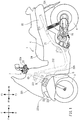
- FIG. 1 is a left side view of the entire vehicle 1 when viewed from the left.
- the vehicle 1 includes a vehicle body 2, a pair of left and right front wheels 3, a rear wheel 4, a linkage mechanism 5, and a steering mechanism 7.
- the vehicle body 2 includes a body frame 21, a body cover 22, a sheet 24, and a power unit 25.
- the body frame 21 is in an upright position.
- the following description with reference to FIG. 1 is based on a premise that the body frame 21 is in the upright position.
- the vehicle 1 is a leaning vehicle. While the vehicle 1 is turning, the body frame 21 tilts in the turning direction.
- the body frame 21 includes a head pipe 211, a down frame 212, and a rear frame 213. In FIG. 1 , a portion of the body frame 21 hidden by the body cover 22 is indicated by broken lines.
- the body frame 21 supports the sheet 24 and the power unit 25.
- the power unit 25 supports the rear wheel 4.
- the power unit 25 includes a driving source such as an engine, an electric motor, or a battery, and a device such as a transmission.
- the head pipe 211 is disposed in a front portion of the vehicle 1. When viewed from a side of the body frame 21, an upper portion of the head pipe 211 is disposed behind a lower portion of the head pipe 211.
- the down frame 212 is connected to the head pipe 211.
- the down frame 212 is disposed behind the head pipe 211.
- the down frame 212 extends in the top-bottom direction of the body frame 21.
- the rear frame 213 is disposed behind the down frame 212.
- the rear frame 213 extends in the front-rear direction of the body frame 21.
- the rear frame 213 supports the sheet 24 and the power unit 25.
- the body cover 22 includes a front cover 221, a front spoiler 222, a pair of left and right front fenders 223, a rear fender 224, and a leg shield 225.
- the body cover 22 is a body part covering at least a portion of body parts mounted on the vehicle 1, such as the pair of left and right front wheels 3, the body frame 21, and the linkage mechanism 5.
- FIG. 2 is a front view of a front portion of the vehicle 1 when viewed from the front of the body frame 21.
- the body frame 21 is in an upright position.
- the following description with reference to FIG. 2 is based on a premise that the body frame 21 is in the upright position.
- FIG. 2 illustrates a state where the front cover 221, the front spoiler 222, and the pair of left and right front fenders 223 are detached.
- the pair of front wheels 3 includes a right wheel 31 and a left wheel 32 arranged at the right and left of the head pipe 211 (body frame 21).
- the linkage mechanism 5 and suspensions (a right suspension 33 and a left suspension 35) are disposed between the head pipe 211 as a part of the body frame 21 and the pair of front wheels 3. That is, the body frame 21 is connected to the right wheel 31 and the left wheel 32 through the linkage mechanism 5 and the suspensions 33 and 35.
- the linkage mechanism 5 is disposed below a handlebar 23.
- the linkage mechanism 5 is disposed above the right wheel 31 and the left wheel 32.
- the linkage mechanism 5 is connected to the right wheel 31 and the left wheel 32 through the suspensions 33 and 35.
- the arrangement of the suspensions 33 and 35 is not limited to this example.
- the suspensions may be disposed in a part of the linkage mechanism 5.
- the suspensions may be disposed between the linkage mechanism 5 and the body frame 21.
- the linkage mechanism 5 of the vehicle 1 illustrated in FIG. 2 is a linkage mechanism of a parallel four-bar linkage (also called parallelogram linkage) type linkage mechanism.
- the linkage mechanism 5 includes an upper arm 51, a lower arm 52, a right side member 53, and a left side member 54.
- the linkage mechanism 5 includes the upper arm 51 and the lower arm 52 (hereinafter collectively referred to as arms 51 and 52 when not specifically distinguished) rotatably supported on the body frame 21.
- the arms 51 and 52 are rotatable about rotation axes extending in the front-rear direction with respect to the body frame 21.
- the rotation axes are disposed at the centers of the arms 51 and 52 in the left-right direction. That is, intermediate portions of the arms 51 and 52 are supported by the head pipe 211 on support parts A and D.
- the rotation axes of the arms 51 and 52 pass through the support parts A and D.
- the right wheel 31 is disposed at the right of the rotation axes
- the left wheel 32 is disposed at the left of the rotation axes.
- the right wheel 31 is connected to right portions of the arms 51 and 52 relative to the rotation axes through the right side member 53 and the right suspension 33.
- the left wheel 32 is connected to left portions of the arms 51 and 52 relative to the rotation axes through the left side member 54 and the left suspension 35.
- the body frame 21 tilts in the left direction or in the right direction relative to the vertical direction. Accordingly, by adjusting the rotations of the arms 51 and 52 with respect to the body frame 21, a tilt in the left direction or in the right direction, that is, the roll angle, of the body frame 21 may be controlled.
- the upper arm 51 includes a pair of plate-shaped members 512.
- the pair of plate-shaped members 512 is disposed ahead of and behind the head pipe 211. Each of the plate-shaped members 512 extends in the left-right direction of the body frame 21.
- the lower arm 52 includes a pair of plate-shaped members 522. The pair of plate-shaped members 522 is disposed ahead of and behind the head pipe 211. Each of the plate-shaped members 522 extends in the left-right direction of the body frame 21.
- the lower arm 52 is disposed below the upper arm 51.
- the length of the lower arm 52 in the left-right direction of the body frame 21 is equal to or approximately equal to the length of the upper arm 51 in the left-right direction of the body frame 21.
- the lower arm 52 extends in parallel with the upper arm 51.
- the configurations of the arms 51 and 52 are not limited to the above example.
- the arms 51 and 52 may be constituted by one plate-like member disposed ahead of the head pipe 211.
- the right end of the upper arm 51 and the right end of the lower arm 52 are connected to the right side member 53 extending in the top-bottom direction of the body frame 21.
- the right side member 53 is rotatably supported by the upper arm 51 and the lower arm 52 on support parts B and E.
- the right side member 53 is rotatable about rotation axes passing through the support parts B and E in the front-rear direction with respect to the upper arm 51 and the lower arm 52.
- the left end of the upper arm 51 and the left end of the lower arm 52 are connected to the left side member 54 extending in the top-bottom direction of the body frame 21.
- the left side member 54 is rotatably supported by the upper arm 51 and the lower arm 52 on support parts C and F.
- the left side member 54 is rotatable about rotation axes passing through the support parts C and F in the front-rear direction with respect to the upper arm 51 and the lower arm 52.
- the lower end of the right side member 53 is connected to the right suspension 33 through a right bracket 317.
- the lower end of the left side member 54 is connected to the left suspension 35 through a left bracket 327.
- the right suspension 33 and the left suspension 35 may extend and contract in the top-bottom direction of the body frame 21.
- the upper end of the right suspension 33 is connected to the linkage mechanism 5, and the lower end of the right suspension 33 is connected to the right wheel 31.
- the upper end of the left suspension 35 is connected to the linkage mechanism 5, and the lower end of the left suspension 35 is connected to the left wheel 32.
- the suspensions 33 and 35 are telescopic suspensions, for example.
- the suspensions may also be referred to as buffers.
- the right suspension 33 includes a right outer cylinder 312 supporting the right wheel 31 and a right inner cylinder 316 disposed in an upper portion of the right outer cylinder 312.
- the upper end of the right inner cylinder 316 is fixed to the right bracket 317, and the lower end of the right inner cylinder 316 is inserted in the right outer cylinder 312.
- the left suspension 35 includes a left outer cylinder 322 supporting the left wheel 32 and a left inner cylinder 326 disposed in an upper portion of the left outer cylinder 322.
- the upper end of the left inner cylinder 326 is fixed to the left bracket 327, and the lower end of the left inner cylinder 326 is inserted in the left outer cylinder 322.
- the left suspension 35 extends and contracts.
- a right rotation prevention mechanism 34 is connected between the right bracket 317 and the right outer cylinder 312.
- the right rotation prevention mechanism 34 prevents the right outer cylinder 312 from rotating about an axis extending in the extension/contraction direction of the right suspension 33 with respect to the right inner cylinder 316.
- a left rotation prevention mechanism 36 is connected to between the left bracket 327 and the left outer cylinder 322.
- the left rotation prevention mechanism 36 prevents the left outer cylinder 322 from rotating about an axis extending in the extension/contraction direction of the left suspension 35 with respect to the left inner cylinder 326.
- the right rotation prevention mechanism 34 includes a right rotation prevention rod 341, a right guide 313, and the right bracket 317.
- the right guide 313 is fixed to an upper portion of the right outer cylinder 312.
- the right guide 313 includes a right guide cylinder 313b in a front portion thereof.
- the right rotation prevention rod 341 extends in parallel with the right inner cylinder 316. An upper portion of the right rotation prevention rod 341 is fixed to a front portion of the right bracket 317. The right rotation prevention rod 341 is disposed ahead of the right inner cylinder 316 with a part of the right rotation prevention rod 341 being inserted in the right guide cylinder 313b. Accordingly, the right rotation prevention rod 341 does not move relative to the right inner cylinder 316. With relative movement of the right inner cylinder 316 relative to the right outer cylinder 312 in the direction in which the right outer cylinder 312 extends, the right rotation prevention rod 341 also moves relative to the right guide cylinder 313b. On the other hand, rotation of the right outer cylinder 312 about an axis extending in the extension/contraction direction of the right suspension 33 with respect to the right inner cylinder 316 is prevented.
- the left rotation prevention mechanism 36 includes a left rotation prevention rod 361, a left guide 323, and the left bracket 327.
- the left guide 323 is fixed to an upper portion of the left outer cylinder 322.
- the left guide 323 includes a left guide cylinder 323b in a front portion thereof.
- the left rotation prevention rod 361 extends in parallel with the left inner cylinder 326. An upper portion of the left rotation prevention rod 361 is fixed to a front portion of the left bracket 327. The left rotation prevention rod 361 is disposed ahead of the left inner cylinder 326 with a part of the left rotation prevention rod 361 being inserted in the left guide cylinder 323b. Accordingly, the left rotation prevention rod 361 does not move relative to the left inner cylinder 326. With relative movement of the left inner cylinder 326 relative to the left outer cylinder 322 in the direction in which the left outer cylinder 322 extends, the left rotation prevention rod 361 also moves relative to the left guide cylinder 323b. On the other hand, rotation of the left outer cylinder 322 about an axis extending in the extension/contraction direction of the left suspension 35 with respect to the left inner cylinder 326 is prevented.
- the configuration of the suspensions is not limited to the above example.
- the right suspension 33 may be configured in such a manner that two combinations of right outer cylinders 312 and inner cylinders 316 that move relative to each other are arranged side by side.
- the left suspension 35 may be configured in such a manner that two combinations of left outer cylinders 322 and left inner cylinders 326 are arranged side by side.
- This configuration is a double telescopic suspension.
- the outer cylinder and the inner cylinder forming a pair of each of the suspensions 33 and 35 are connected to each other not to move relative to each other so that the suspensions 33 and 35 may also serve as rotation prevention mechanisms.
- the right rotation prevention mechanism 34 and the left rotation prevention mechanism 36 as described above are unnecessary.
- the vehicle 1 includes a roll angle control mechanism 74 for controlling a roll angle of the body frame 21.
- FIG. 2 illustrates the roll angle control mechanism 74 by dotted lines.
- the roll angle control mechanism 74 adjusts rotations of the arms 51 and 52 with respect to the body frame 21. The adjustment of rotation of the arms 51 and 52 controls the roll angle of the body frame 21.
- the roll angle control mechanism 74 is connected to the body frame 21 and to at least one of the arm 51 or the lower arm 52.
- the adjustment of rotations of the arms 51 and 52 by the roll angle control mechanism 74 is not only for simply locking and unlocking the arms 51 and 52 but also for controlling a rotary force. That is, the roll angle control mechanism 74 may be configured to adjust rotations of the arms 51 and 52 by generating a torque for rotating the arms 51 and 52 with respect to the body frame 21 or a resistance to such a torque. For example, the roll angle control mechanism 74 may be configured to enable a change in the magnitude of a force for rotating the arms 51 and 52.
- the roll angle control mechanism 74 may adjust rotations of the arms 51 and 52 so that the roll angle of the body frame 21 reaches an arbitrarily set target value. At this time, the roll angle control mechanism 74 may monitor an actual roll angle of the body frame 21 or a torque to the arms 51 and 52, and by using a monitoring result, determine a magnitude and an orientation of a force for rotating the arms 51 and 52.
- FIG. 3 is a left side view of a front portion of the vehicle 1 when viewed from the left of the body frame 21.
- the body frame 21 is in the upright position.
- the following description with reference to FIG. 3 is based on a premise that the body frame 21 is in the upright position.
- FIG. 3 illustrates a state where the front cover 221, the front spoiler 222, and the pair of left and right front fenders 223 are detached.
- the left side member 54 and a left transfer plate 63 are not shown in FIG. 3 .
- the roll angle control mechanism 74 includes an actuator 42 for adjusting the rotations of the arms 51 and 52 with respect to the body frame 21.
- the actuator 42 is connected to the head pipe 211 (body frame 21) through a support member 43.
- the support member 43 fixes the actuator 42 to the body frame 21.
- the actuator 42 includes an output member 461 that applies a rotary force to the upper arm 51 while being in contact with the upper arm 51.
- the output member 461 is an output shaft that rotates about an axis.
- the output shaft of the output member 461 is coaxial with the rotation axis of the upper arm 51. Rotations of these output shafts are transferred to the rotation axis of the upper arm 51.
- the actuator 42 may include a motor as a power source and a speed reducer that reduces the rotation speed of the motor and outputs the reduced speed.
- the speed reducer may be, for example, a deceleration gear that operates in conjunction with rotation of the motor.
- the output member 461 transfers rotations of the motor and the speed reducer to the outside.
- the actuator 42 may operate based on a control signal from a control section (not shown) included in the vehicle 1. For example, the actuator 42 may adjust a rotary force to be applied to the arms 51 and 52 so that the roll angle of the body frame 21 reaches a target value indicated by the control section.
- the actuator 42 may also control an output based on a signal from a sensor that detects a state of the vehicle 1. Examples of sensors indicating the state of the vehicle includes a posture sensor for detecting a posture of the vehicle 1 and a torque sensor for detecting a torque for rotations of the arms 51 and 52 with respect to the body frame.
- a process of determining an output of the actuator 42 based on information from the sensor may be executed by a control circuit or a control computer incorporated in the actuator 42 or may be executed by a control device external to the actuator 42.
- the configuration of the actuator 42 is not limited to the above example.
- the actuator 42 may be configured to be connected to at least one of the upper arm 51 and the lower arm 52 and adjust rotation of the at least one of the upper arm 51 and the lower arm 52.
- the output member of the actuator 42 may be an axial shape extending in a single-axis direction so that when the output member axially contracts, the output member applies a rotary force to the arms 51 and 52.
- the actuator may be configured in such a manner that one end of the actuator is rotatably connected to the arms 51 and 52 and the other end of the actuator is rotatably connected to the body frame 21. The one end is connected to a portion away from the rotation axes of the arms 51 and 52.
- the actuator 42 may be a hydraulic actuator. That is, a power source of the actuator may be electric or hydraulic.
- the actuator 42 may be a damper device that applies a damping force to a torque for rotating the arms 51 and 52.
- the vehicle 1 may include suspension control mechanisms that reduce extension and contraction of the suspensions 33 and 35 (see FIG. 2 ).
- the suspension control mechanisms may be disposed inside the suspensions 33 and 35, for example.
- the suspensions 33 and 35 include inner cylinders 316 and 326 and outer cylinders 312 and 322. With extension and contraction of the suspensions 33 and 35, a flow of oil occurs in the suspensions.
- orifices that are oil channels and regulating valves for regulating flow rates in the oil channels are provided in the suspensions.
- the suspension control mechanisms may be configured to control the regulating valves. Adjusting mechanism for adjusting the regulating valves may be mechanical or electric.
- each of the mechanisms may be configured to control the position of the regulating valve by using a motor or a solenoid, for example.
- the regulating valves may be electromagnetic regulating valves.
- Each of the suspension control mechanisms may have a configuration that adjusts a magnetic fluid viscosity with a solenoid.
- the suspension control mechanisms may control the regulating valves based on a signal from the control section of the vehicle 1.
- the suspension control mechanisms control opening and closing of the regulating valves to thereby regulate the flow rates of oil in the suspensions 33 and 35.
- the suspension control mechanisms may suppress extension and contraction of the suspensions 33 and 35 by reducing the flow rates.
- the suspension control mechanisms may cancel suppression of extension and contraction of the suspensions 33 and 35 by increasing the flow rates. For example, when the regulating valves are closed, extension and contraction of the suspensions 33 and 35 are suppressed, whereas when the regulating valves are opened, suppression of extension and contraction of the suspensions 33 and 35 are canceled (operations of extension and contraction are allowed).
- suspension control mechanisms may be provided to the right rotation prevention mechanism 34 and the left rotation prevention mechanism 36.
- brake shoes may be provided to guide cylinders 313b and 323b in which the rotation prevention rods 341 and 361 are inserted. When the brake shoes are actuated, the brake shoes contact the rotation prevention rods 341 and 361 and lock relative movements of the rotation prevention rods 341 and 361 relative to the guide cylinders 313b and 323b.
- Each of the brake shoes may be actuated by an actuator such as a motor or a hydraulic actuator, for example.
- the actuator for the brake shoes may be attached to, for example, the body frame 21.
- the configuration of the brakes used as the suspension control mechanisms is not limited to the above example.
- the brakes may have a configuration including a caliper or a configuration that restricts extension and contraction of the suspensions by breaking a parallel relationship between the extension/contraction direction of the rotation prevention mechanisms and the extension/contraction direction of the suspensions.
- the suspension control mechanism is provided independently of the actuator 42 of the roll angle control mechanism 74.
- an actuator for suppressing extension and contraction of the suspensions 33 and 35 is additionally provided.
- the power source of the suspension control mechanism may be provided independently of the power source of the roll angle control mechanism 74. Accordingly, extension and contraction of the suspensions 33 and 35 may be controlled without constraint of roll angle control.
- the roll angle control may be performed independently of control of the extension and contraction of the suspensions 33 and 35.
- the steering mechanism 7 includes the handlebar 23 and the steering force transfer mechanism 6.
- the steering force transfer mechanism 6 includes a steering shaft 60 and a tie rod 67.
- the steering force transfer mechanism 6 also includes the brackets 317 and 327 and the suspensions 33 and 35.
- the steering force transfer mechanism 6 is rotatably supported on the head pipe 211 in a front portion of the body frame 21, integrally with the handlebar 23.
- the steering force transfer mechanism 6 changes the directions of the right wheel 31 and the left wheel 32 in accordance with rotation of the handlebar 23. That is, the steering force transfer mechanism 6 transfers a steering force input to the handlebar 23 with a rider's operation of the handlebar 23, to the right wheel 31 and the left wheel 32 through the right bracket 317 and the left bracket 327.
- the rotation axis Z of the steering shaft 60 extends in the top-bottom direction of the body frame 21.
- the handlebar 23 is attached to an upper portion of the steering shaft 60.
- the steering shaft 60 rotates about the rotation axis Z in accordance with an operation of the handlebar 23 by a rider.
- a part of the steering shaft 60 is rotatably supported on the head pipe 211.
- a lower portion of the steering shaft 60 is connected to the tie rod 67 extending in the left-right direction through an intermediate transfer plate 61.
- the intermediate transfer plate 61 is relatively non-rotatable with respect to the steering shaft 60. That is, the intermediate transfer plate 61 is rotatable together with the steering shaft 60 about the direction in which the steering shaft 60 extends.
- the right end of the tie rod 67 is connected to the right bracket 317 through a right transfer plate 62.
- the right transfer plate 62 is rotatable together with the right side member 53 about the direction in which the right side member 53 extends.
- the left end of the tie rod 67 is connected to the left bracket 327 through a left transfer plate 63.
- the left transfer plate 63 is rotatable together with the left side member 54 about the direction in which the left side member 54 extends.
- FIG. 4 is a plan view of a front portion of the vehicle 1 when viewed from above the body frame 21.
- the body frame 21 is in the upright position.
- the following description with reference to FIG. 4 is based on a premise that the body frame 21 is in the upright position.
- FIG. 4 illustrates a state where the front cover 221 is detached.
- the direction in which the right side member 53 extends is defined as a right center axis X
- the direction in which the left side member 54 is defined as a left center axis Y.
- the right center axis X and the left center axis Y extend in parallel with the rotation axis Z of the steering shaft 60.
- the intermediate transfer plate 61, the right transfer plate 62, and the left transfer plate 63 are connected to the tie rod 67 through an intermediate front rod 641, a right front rod 651, and a left front rod 661, respectively.
- the intermediate front rod 641, the right front rod 651, and the left front rod 661 extend in the front-rear direction of the body frame 21, and are rotatable about the direction in which these rods extend. Accordingly, the intermediate front rod 641, the right front rod 651, and the left front rod 661 are connected to the tie rod 67 to be rotatable about an axis extending in the front-rear direction.
- the intermediate front rod 641, the right front rod 651, and the left front rod 661 are connected to the intermediate transfer plate 61, the right transfer plate 62, and the left transfer plate 63 through an intermediate joint 64, a right joint 65, and a left joint 66, respectively.
- the intermediate front rod 641 is relatively rotatable about an axis parallel to the rotation axis Z with respect to the intermediate transfer plate 61.
- the right front rod 651 is relatively rotatable about an axis parallel to the right center axis X with respect to the right transfer plate 62.
- the left front rod 661 is relatively rotatable about an axis parallel to the left center axis Y with respect to the left transfer plate 63.
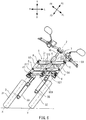
- FIG. 5 is a plan view of a front portion of the vehicle 1 when viewed from above the body frame 21 in a state where the right wheel 31 and the left wheel 32 are steered rightward.
- the steering shaft 60 rotates about the rotation axis Z with respect to the head pipe 211.
- the steering shaft 60 rotates in the direction of arrow G.
- the intermediate transfer plate 61 rotates about the rotation axis Z in the direction of arrow G with respect to the head pipe 211.
- the intermediate front rod 641 of the tie rod 67 rotates about the intermediate joint 64 in the direction opposite to arrow G with respect to the intermediate transfer plate 61. Accordingly, the tie rod 67 moves right-rearward while maintaining its posture.
- the right front rod 651 and the left front rod 661 of the tie rod 67 rotate about the right joint 65 and the left joint 66, respectively, in the direction opposite to arrow G. Accordingly, the right transfer plate 62 and the left transfer plate 63 rotate in the direction of arrow G while the tie rod 67 maintains its posture.
- the right bracket 317 With the rotation of the right transfer plate 62 in the direction of arrow G, the right bracket 317, which is relatively non-rotatable with respect to the right transfer plate 62, rotates about the right center axis X in the direction of arrow G with respect to the right side member 53.
- the left bracket 327 which is relatively non-rotatable with respect to the left transfer plate 63, rotates about the left center axis Y in the direction of arrow G with respect to the left side member 54.
- the right suspension 33 which is connected to the right bracket 317 through the right inner cylinder 316, rotates about the right center axis X in the direction of arrow G with respect to the right side member 53. Accordingly, the right wheel 31 supported by the right suspension 33 rotates about the right center axis X in the direction of arrow G with respect to the right side member 53.
- the left suspension 35 which is connected to the left bracket 327 through the left inner cylinder 326, rotates about the left center axis Y in the direction of arrow G with respect to the left side member 54. Accordingly, the left wheel 32 supported by the left suspension 35 rotates about the left center axis Y in the direction of arrow G with respect to the left side member 54.
- the steering force transfer mechanism 6 transfers a steering force to the right wheel 31 and the left wheel 32 in accordance with an operation of the handlebar 23 by the rider.
- the right wheel 31 and the left wheel 32 rotate about the right center axis X and the left center axis Y, respectively, in the directions in accordance with the operation direction of the handlebar 23 by the rider.
- FIG. 6 is a front view of a front portion of the vehicle 1 in a state where the body frame 21 tilts leftward when viewed from the front of the body frame 21.
- the linkage mechanism 5 forms a rectangle when the vehicle 1 is viewed from the front of the body frame 21.
- the linkage mechanism 5 forms a parallelogram when the vehicle 1 is viewed from the front of the body frame 21.
- the deformation of the linkage mechanism 5 is in conjunction with the tilt of the body frame 21 in the left direction or in the right direction. Actuation of the linkage mechanism 5 means that the upper arm 51, the lower arm 52, the right side member 53, and the left side member 54 constituting the linkage mechanism 5 relatively rotate about the rotation axes respectively passing through the support parts A through F thereof so that the linkage mechanism 5 is thereby deformed.
- the head pipe 211 that is, the body frame 21, tilts leftward relative to vertical direction.
- the upper arm 51 rotates about the axis passing through the support part A counterclockwise with respect to the body frame 21 when viewed from the rider.
- the lower arm 52 rotates counterclockwise about the axis passing through the support part D. Accordingly, the upper arm 51 moves leftward relative to the lower arm 52.
- the upper arm 51 With the leftward movement of the upper arm 51, the upper arm 51 rotates about the axis passing through the support part B and the axis passing through the support part C counterclockwise with respect to the right side member 53 and the left side member 54, respectively.
- the lower arm 52 rotates about the axis passing through the support part E and the axis passing through the support part F counterclockwise with respect to the right side member 53 and the left side member 54, respectively. Accordingly, the right side member 53 and the left side member 54 tilt leftward relative to the vertical direction while maintaining a posture parallel to the body frame 21.
- the lower arm 52 moves leftward relative to the tie rod 67.
- the intermediate front rod 641, the right front rod 651, and the left front rod 661 of the tie rod 67 rotate with respect to the tie rod 67. Accordingly, the tie rod 67 maintains a posture parallel to the upper arm 51 and the lower arm 52.
- the right wheel 31 which is connected to the right side member 53 through the right bracket 317 and the right suspension 33, tilts leftward while maintaining a posture parallel to the body frame 21.
- the left wheel 32 which is connected to the left side member 54 through the left bracket 327 and the left suspension 35, tilts leftward while maintaining a posture parallel to the body frame 21.
- the tilt operations of the right wheel 31 and the left wheel 32 have been described with respect to the vertical direction.
- the top-bottom direction of the body frame 21 does not coincide with the vertical direction.
- the linkage mechanism 5 tilts the body frame 21 relative to the vertical direction by changing the relative positions of the right wheel 31 and the left wheel 32 relative to the body frame 21 in the top-bottom direction of the body frame 21.
- FIG. 7 is a block diagram illustrating an example configuration of a control system of the vehicle 1.
- the control section 71 controls a roll angle control mechanism 74 and a suspension control mechanism 75 based on information indicating a vehicle state.
- the control section 71 is connected to the roll angle control mechanism 74 and the suspension control mechanism 75 wirelessly or by wire.
- the control section 71 is configured to enable transmission of a control signal to a driving unit of the roll angle control mechanism 74 and a driving unit of the suspension control mechanism 75.
- the driving unit of the roll angle control mechanism 74 may be, for example, a driving unit or the like of the actuator 42 of the roll angle control mechanism 74.
- the driving unit of the suspension control mechanism 75 may be, for example, an actuator, an attenuating circuit, or another component of the suspension control mechanism 75.
- the control section 71 is connected to a sensor for detecting a state of the vehicle 1 wirelessly or by wire.
- the control section 71 receives information indicating the state of the vehicle 1 from the sensor.
- a steering angle sensor 76, a throttle sensor 77, a vehicle speed sensor 78, and a posture angle sensor 79 are connected to the control section 71.
- the steering angle sensor 76 sends, to the control section 71, a signal in accordance with the rotation angle and the rotation direction of the steering shaft 60.
- the steering angle sensor 76 is, for example, attached to the steering shaft 60 and detects rotation of the steering shaft 60 with respect to the body frame 21.
- the throttle sensor 77 sends a signal in accordance with a throttle opening degree of the vehicle 1 to the control section 71.
- the throttle sensor 77 is attached to the engine of the vehicle 1, for example, and detects a throttle opening degree of a throttle valve of the engine.
- the vehicle speed sensor 78 sends a signal in accordance with a traveling speed of the vehicle 1 to the control section 71.
- the vehicle speed sensor 78 may detect a rotation speed of the wheel.
- the vehicle speed sensor 78 is attached to, for example, an axle of the front wheels 3 or the rear wheel 4 or an output shaft of a transmission, and sends a signal in accordance with the rotation speed of the wheel to the control section 71.
- the posture angle sensor 79 sends a signal in accordance with a roll angle of the body frame 21 to the control section 71.
- the posture angle sensor 79 may be a gyroscope for detecting a roll angular velocity and a roll angle of the body frame 21.
- the gyroscope may be a three-axis gyroscope for detecting angular velocities or angles of a yaw angle and a pitch angle in addition to the roll angle.
- the posture angle sensor 79 is not limited to a gyroscope.
- the posture angle sensor 79 may be an acceleration sensor, a sensor for detecting rotation angles, angular velocities, or torques of the arms 51 and 52 with respect to body frame 21, or a sensor for detecting an angle of a pendulum hanging from the body frame 21, a sensor for detecting a torque applied to the actuator, or a current detector of the actuator, or a combination of at least these two sensors.
- the control section 71 may receive information from an acceleration sensor in three-axis directions, an angular acceleration sensor for three axes, a steering torque sensor, an engine torque sensor, an engine revolution speed sensor, a seat pressure sensor, or a stroke sensor for detecting the operation amount of a brake, for example.
- the control section 71 includes a determination section 72 and an angle control section 73.
- the determination section 72 determines control of the roll angle and control of extension and contraction of the suspensions based on information acquired from the group of the sensors 77 through 79 and indicating the vehicle state
- the angle control section 73 controls the roll angle control mechanism based on the roll angle control determined by the determination section 72 and the roll angle of the body frame 21 detected by the posture angle sensor 79.
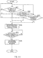
- the determination section 72 determines whether roll angle control during traveling toward stop is necessary or not based on information acquired from at least one of the group of the sensors 77 through 79 and indicating the vehicle state. This determination includes determination of start or cancel of roll angle control during traveling toward stop. For example, the determination section 72 may determine whether roll angle control during traveling toward stop is necessary or not based on predetermined conditions for the vehicle state. If the vehicle state satisfies a first condition, for example, the determination section 72 may determine to start roll angle control during traveling toward stop, whereas if the vehicle state satisfies a second condition, the determination section 72 may determine to cancel the roll angle control.
- the state of "during traveling toward stop” is, for example, a traveling state determined to be highly probably stopped within several seconds. Determination on whether the vehicle is traveling toward stop or not is based on, for example, whether the vehicle speed is below a predetermined threshold or not. If the vehicle 1 shows a behavior of traveling toward stop, the determination section 72 determines to perform roll angle control during traveling toward stop. Accordingly, in a case where the vehicle increases the speed again from a decelerated state for stop, for example, the determination section 72 might determine to perform roll angle control during traveling toward stop in some cases.
- the low-speed traveling range refers to a range in which the vehicle speed of the vehicle 1 is lowest among a plurality of ranges obtained by dividing the entire vehicle-speed range except for a stopped state. That is, the entire vehicle-speed range of the vehicle 1 except for the stopped state may be divided into a high-speed traveling range and the low-speed traveling range.
- the low-speed traveling range may be set as a range where the vehicle speed v is higher than zero and is lower than an upper limit VLu (i.e., 0 ⁇ v ⁇ VLu).
- the high-speed traveling range is a range where the vehicle speed v is VLu or more and is a maximum speed Vmax of the vehicle 1 or less (i.e., VLu ⁇ v ⁇ Vmax).
- the upper limit VLu of the low-speed traveling range is not limited to a specific value, and is set at a value depending on the type of the vehicle.
- the threshold Th2 of the vehicle speed for determining whether the vehicle is traveling toward stop or not is a value of the vehicle speed included in the low-speed traveling range.
- the roll angle control during traveling toward stop may be, for example, control of causing the roll angle to approach a set target value.
- the target value is determined by the control section 71 based on an input to the vehicle from the rider.
- the determination of the target value may be performed by any one of the determination section 72 or the angle control section 73.
- the control section 71 determines a target value in accordance with an input to the vehicle from the rider when the determination section 71 determines that the vehicle state satisfies the first condition.
- the control section 71 detects an input to the vehicle from the rider.
- a point of time when it is determined that the vehicle state satisfies the first condition and a point of time when the input to the vehicle from the rider is detected do not need to be strictly the same.
- the control section 7 may detect the input to the vehicle from the rider from information obtained by the group of the sensors 77 through 79 for detecting the vehicle state. For example, the control section 7 may use information acquired from the group of the sensors 77 through 79 as information indicating an input to the vehicle from the rider or may use the information acquired from the group of the sensors 77 through 79 for determining an input to the vehicle from the rider.
- Examples of the information detected by vehicle-mounted sensors as an input to the vehicle from the rider include a vehicle speed, an acceleration, a throttle opening degree, an operating state of a brake, a roll angle of the body frame 21, a barycenter shift of the vehicle, a steering angle of the handlebar, motions of the body frame in three directions (acceleration, speed, and position), motions about three axes (acceleration, angular velocity, angle), and a pressure of a sheet.
- the control section 71 may also determine an input to the vehicle from the rider from a combination of information detected by a plurality of sensors.
- the input to the vehicle from the rider includes a case where the input is zero. That is, the control section 7 may determine roll angle control based on that no input is made from the rider to the vehicle for an event or that a value indicating an input is zero for an event. For example, in a case where the rider keeps the body frame 21 in the upright position during traveling, the detected roll angle is zero degrees, and a change in the roll angle over time is also zero. In such a case, the information that the roll angle or a change in the roll angle is zero may be used for determining an operation of the control section 7.
- control section 71 detects the roll angle of the body frame 21 as an input to the vehicle from a rider, as an example. If the control section 71 determines that the state of the vehicle 1 satisfies the first condition, the control section 71 acquires a roll angle of the body frame 21 from the posture angle sensor 79. Accordingly, the roll angle of the body frame 21 in the case where the state of the vehicle 1 satisfies the first condition may be acquired. The control section 71 sets the acquired roll angle as a target value. The angle control section 73 controls the roll angle control mechanism 74 to cause the roll angle of the body frame 21 to reach the set target value.
- the roll angle of the body frame 21 obtained when the state of the vehicle 1 is determined to satisfy the first condition, that is, when the vehicle becomes a traveling state toward stop, is maintained.
- This roll angle may be maintained at and after the stop of the vehicle 1. Accordingly, traveling toward stop and stop of the vehicle may be performed in a vehicle posture in accordance with a rider's intention.
- the control section 71 may update the target value of the roll angle in accordance with an input to the vehicle 1 from the rider after the determination that the state of the vehicle 1 satisfies the first condition, that is, in a period in which the roll angle control during traveling toward stop is performed.
- the target value may be updated in accordance with an actual roll angle of the body frame 21.
- control section 71 may control the roll angle control mechanism in accordance with an operation of the rider during traveling toward stop to cause the roll angle of the body frame 21 to approach zero degrees with respect to the vertical direction. That is, in a case where the rider performs an operation of causing the roll angle of the body frame to approach zero degrees with respect to the vertical direction in the period in which roll angle control during traveling toward stop is performed, the control section 71 may control the roll angle control mechanism in accordance with the operation of the rider to cause the roll angle of the body frame 21 to approach zero degrees with respect to the vertical direction. At this time, when the roll angle of the body frame 21 changes to approach zero degrees from the target value with respect to the vertical direction, the control section 71 sets the roll angle after the change as a target value.
- control may be performed in such a manner that during traveling toward stop and after the stop, a rider's operation of tilting the vehicle in a direction in which the roll angle of the body frame approaches zero degrees is permitted, but a rider's operation of tilting the vehicle in the opposite direction is not permitted.
- the roll angle of the body frame approaches zero degrees with respect to the vertical direction means that, when supposing the roll angle of the body frame in a case where the top-bottom direction of the body frame coincides with the vertical direction to be zero degrees, the roll angle changes to approach zero degrees.
- the determination section 72 determines whether extension and contraction of the suspensions 33 and 35 are necessary or not based on information indicating the vehicle state and acquired from at least one of the group of the sensors 77 through 79. This necessity determination includes determination on start or cancel of suppression of extension and contraction of the suspensions 33 and 35. For example, it may be determined whether suppression of extension and contraction of the suspensions 33 and 35 based on predetermined conditions of the vehicle state. If the vehicle state satisfies a third condition, for example, the determination section 72 determines to start suppression of extension and contraction of the suspensions 33 and 35, whereas if the vehicle state satisfies a fourth condition, the determination section 72 determines to cancel suppression of extension and contraction of the suspensions 33 and 35.
- the suppression of extension and contraction of the suspensions 33 and 35 may be a mode of locking to prevent extension and contraction of the suspensions 33 and 35, for example.
- the suppression of extension and contraction of the suspensions 33 and 35 may be a mode of applying a resistance against a force of extension and contraction of the suspensions 33 and 35 or a mode of increasing such a resistance.
- the determination section 72 may determine to reduce extension and contraction of the suspensions 33 and 35. That is, the first through fourth conditions may be set in such a manner that extension and contraction of the suspensions 33 and 35 are suppressed in at least a part of a period in which the roll angle control during traveling toward stop is performed. For example, by making the first condition and the third conditions the same, the determination section 72 may determine to start roll angle control during traveling toward stop and suppression of extension and contraction of the suspensions 33 and 35 at the same time. Alternatively, by making the first condition and the third condition different from each other, the determination section 72 may start suppression of extension and contraction of the suspensions 33 and 35 and start roll angle control during traveling toward stop at different times. Alternatively, the determination section 72 may include start of roll angle control during traveling toward stop in a condition for start of suppression of extension and contraction of the suspensions.
- the determination section 72 may perform determination in such a manner that the roll angle control during traveling toward stop continues after stop of the vehicle.
- the second condition may be set not to cancel the roll angle control during traveling toward stop even when the vehicle 1 stops.
- a condition in which the vehicle speed exceeds a predetermined threshold may be included in the second condition. In this case, if the vehicle 1 stops and then starts traveling so that the vehicle speed exceeds the threshold, the determination section 72 may determine to cancel roll angle control during traveling toward stop.
- the determination section 72 may still continue suppression of extension and contraction of the suspensions after stop of the vehicle.
- the fourth condition may be set in such a manner that suppression of extension and contraction of the suspensions is not canceled even when the vehicle 1 stops.
- a condition in which the vehicle speed exceeds a predetermined threshold may be included in the fourth condition. In this case, if the vehicle 1 stops and then starts traveling so that the vehicle speed exceeds the threshold, the determination section 72 may determine to cancel suppression of extension and contraction of the suspensions.
- the determination section 72 may determine whether roll angle control during traveling toward stop is necessary or not and whether suppression of extension and contraction of the suspensions is necessary or not, by using a plurality of parameters indicating a vehicle state.
- the plurality of parameters indicating the vehicle state are determined based on information obtained from the sensors 77 through 79.
- the determination section 72 compares the parameters indicating the vehicle state with thresholds to thereby perform the determinations described above.
- These thresholds are data indicating the first through fourth conditions.
- the thresholds may be recorded in a storage unit (e.g., memory) of the control section 71 beforehand. That is, the control section 71 may store data indicating the first through fourth conditions beforehand.
- the determination section 72 may change the thresholds depending on the vehicle state.
- a combination of parameters used for determining whether roll angle control during traveling toward stop is necessary or not may be different from a combination of parameters used for determining whether suppression of extension and contraction of the suspensions is necessary or not.
- At least one parameter used for determining whether roll angle control during traveling toward stop is necessary or not may be the same as a parameter used for determining whether suppression of extension and contraction of the suspensions is necessary or not.
- a threshold of the parameter used for determining whether roll angle control during traveling toward stop is necessary or not may be different from a threshold of the parameter used for determining whether suppression of extension and contraction of the suspensions is necessary or not.
- a combination of parameters used for determining start of roll angle control during traveling toward stop may be constituted by the vehicle speed, the throttle opening degree, and the roll angle, and a combination of parameters used for determining start of suppression of extension and contraction of the suspensions may be constituted by only the vehicle speed.
- a threshold of the vehicle speed used for determining start of roll angle control during traveling toward stop may be different from a threshold of the vehicle speed used for determining start of suppression of extension and contraction of the suspensions.
- the angle control section 73 determines control of rotations of the arms 51 and 52 based on the roll angle of the body frame 21 detected by the posture angle sensor 79.
- the angle control section 73 determines the magnitude and direction of a rotary force as control of rotation, and outputs the magnitude and direction to the roll angle control mechanism 74.
- the angle control section 73 may determine the magnitude and direction of the rotary force applied to the arms 51 and 52 based on a target value of the roll angle and the roll angle detected by the posture angle sensor 79. Accordingly, an actual roll angle of the body frame 21 may be fed back to control by the roll angle control mechanism.
- the angle control section 73 may determine the rotation direction of the arms 51 and 52 that reduces the difference between the target value of the roll angle and the roll angle detected by the posture angle sensor 79, as the direction of a rotation to be applied.
- the angle control section 73 may determine a magnitude of the rotary force to be applied in accordance with the difference between the target value of the roll angle and the roll angle detected by the posture angle sensor 79.
- the angle control section 73 may also determine the magnitude of a rotary force to be applied based on a torque to rotation of the arms 51 and 52 with respect to the body frame 21.
- the control of the angle control section 73 is not limited to the control of reducing the difference between the roll angle detected by the posture angle sensor 79 and the target value of the roll angle.
- the angle control section 73 may determine, for example, an instruction value of a motor of an actuator by using a rotation speed or a torque of the arms with respect to the body frame and a current value of the motor.
- the determination section 72 determines whether the vehicle 1 is stopped or not. For example, in a case where the vehicle speed detected by the vehicle speed sensor 78 is zero, the determination section 72 may determine that the vehicle 1 is stopped. If the determination section 72 determines that the vehicle 1 is stopped, the control section 71 determines a target value of the roll angle during stop in accordance with an input to the vehicle 1 during stop from a rider. Based on the determined target value of the roll angle during stop and the roll angle detected by the posture angle sensor 79, the angle control section 73 determines control of rotation of the arms 51 and 52. The angle control section 73 determines the magnitude and direction of a rotary force as control of rotation, and outputs the magnitude and direction to the roll angle control mechanism 74. The roll angle control mechanism 74 applies a rotary force to the arms 51 and 52 in accordance with an output from the angle control section 73. Accordingly, the roll angle of the body frame 21 is controlled in accordance with the input to the vehicle from the rider during stop.
- the control section 71 may control the roll angle control mechanism so as to change the roll angle of the body frame 21 in accordance with the input to the vehicle 1 from the rider.
- the fifth condition may include another condition in addition to the stopped state of the vehicle 1.
- a state of traveling start preparation of the vehicle 1 may be included, for example. Accordingly, if the state of the vehicle 1 satisfies the fifth condition, for example, the determination section 72 may determine that the vehicle is stopped with a high possibility of start of traveling.
- control section 71 may cause the roll angle control mechanism 74 to control the roll angle during stop in accordance with the input to the vehicle from the rider during stop.
- the fifth condition is not limited to a specific condition, but may be a vehicle state serving as a basis of determination on whether to perform roll angle control during stop or not.
- the fifth condition may include a condition that the engine is running and the rider is seated on the sheet 24.
- the input to the vehicle 1 from the rider during stop may be detected based on information obtained by the group of the sensors 77 through 79 for detecting vehicle states, in a manner similar to that described above.
- description is given on a case where an input to the handlebar during stop is detected as an input to the vehicle 1 from the rider, as an example.
- the control section 71 acquires a steering angle of the handlebar detected by the steering angle sensor 76.
- the steering angle of the handlebar is not necessarily acquired from the steering angle sensor 76.
- a torque of the steering shaft 60 detected by a torque sensor of the steering shaft 60 (an example of a steering torque) may be acquired as an input to the handlebar.
- the control section 71 determines a target value of the roll angle in accordance with at least one of a direction or a degree of the steering angle of the handlebar acquired from the steering angle sensor 76.
- the angle control section 73 controls the roll angle control mechanism 74 so as to cause the roll angle to reach the determined target value.
- the control section 71 may set a target value of the roll angle so as to tilt the vehicle 1 rightward, whereas in a case where the input to the handlebar is in a direction of turning leftward, the control section 71 may set a target value of the roll angle so as to tilt the vehicle 1 leftward.
- the control section 71 may set a target value in such a manner that the roll angle of the vehicle 1 has a degree in accordance with a degree of the steering angle of the handlebar.
- the control section 71 may be constituted by an electronic control unit (ECU).
- the control section 71 may be constituted by a computer including a processor and a memory or a circuit formed on a board.
- the process of the control section 71 is, for example, implemented by reading and executing a program from a memory with the processor.
- Such a program and a non-transitory recording medium in which the program is recorded are also included in the embodiment of the present teaching.
- control section 71 is not limited to the example illustrated in FIG. 7 .
- control section 71 may not have the function of controlling the suspension control mechanism 75.
- the control section 71 may not have the function of controlling the roll angle during traveling toward stop.
- the determination section 72 and the angle control section 73 may be constituted by computers independently of each other or circuits formed on different boards.
- the angle control section 73 may be incorporated in a part of the roll angle control mechanism 74.
- FIG. 8 is a timing chart demonstrating an example of control of a roll angle and a suspension by the control section 71 illustrated in FIG. 7 .
- the abscissa represents time.
- the ordinate represents the vehicle speed or the roll angle.
- the line VI represents a change in the vehicle speed over time, and line R1 represents a change in a roll angle over time.
- the threshold Th1 represents a threshold of the vehicle speed for use in determining start of suppression of extension and contraction of the suspensions (an example of the third condition).
- the threshold Th2 represents a threshold of the vehicle speed for use in determining whether to start roll angle control during traveling toward stop (an example of the first condition).
- the threshold Th3 represents a threshold of a vehicle speed for use in determining whether to cancel suppression of extension and contraction of the suspensions (an example of the fourth condition).
- the threshold Th4 represents a threshold of the vehicle speed for use in determining whether to cancel roll angle control during traveling toward stop (an example of the second condition).
- the determination section 72 determines start of suppression of extension and contraction of the suspensions.
- the control section 71 issues an instruction of suppressing extension and contraction of the suspensions to the suspension control mechanism 75.
- the suspension control mechanism 75 locks the suspensions to prevent the suspensions from extending and contracting.
- the determination section 72 determines to start roll angle control during traveling toward stop. Although not shown, it is assumed that at time t2, the throttle opening degree and the roll angle have already satisfied the condition for starting roll angle control during traveling toward stop (first condition). At time t2, the control section 71 instructs the roll angle control mechanism 74 to control the roll angle during traveling toward stop. In this example, since Th1 > Th2, after the start of suppression of extension and contraction of the suspensions, roll angle control during traveling toward stop starts.
- the determination section 72 sets a roll angle R(t2) at time t2 as a target value of the roll angle during traveling toward stop.
- the angle control section 73 compares the roll angle R(t2) with a roll angle Rs detected by the posture angle sensor 79. If the signs (positive (+) or negative (-)) of R(t2) and Rs are the same and
- , the angle control section 73 determines a rotary force of the arms 51 and 52 in such a manner that Rs R(t2) is established.
- a roll angle in a state where the top-bottom direction of the body frame 21 coincides with the vertical direction (gravity direction) is defined as zero degrees.
- a roll angle in a state where the body frame 21 tilts rightward with respect to the vertical direction is defined as positive (+), and a roll angle in a state where the body frame 21 tilts leftward with respect to the vertical direction is defined as negative (-). In this manner, at and after time t2, the roll angle is kept at R(t2).
- the threshold Th3 > if the vehicle speed is zero, it is determined that the condition for starting roll angle control during traveling toward stop (first condition) is satisfied and the condition for canceling the roll angle control (second condition) is not satisfied.
- the threshold Th4 > if the vehicle speed is zero, it is determined that the condition for starting suspension suppression control (third condition) is satisfied and the condition for canceling the suspension suppression control (fourth condition) is not satisfied.
- FIG. 9 is a flowchart depicting an example process in which the determination section 72 determines whether to start roll angle control and suppression of extension and contraction of the suspensions during traveling toward stop.
- the determination section 72 determines whether or not the vehicle speed is a threshold or less (S1). If the vehicle speed is the threshold or less, the determination section 72 determines to start suppression of extension and contraction of the suspensions (S2).
- the determination section 72 determines whether or not each of the throttle opening degree, the vehicle speed, and the roll angle is within a threshold, inclusive (S3 through S5). If each of the throttle opening degree, the vehicle speed, and the roll angle is within the threshold, inclusive, the determination section 72 determines start of roll angle control during traveling toward stop (S6).
- the determination section 72 records a roll angle (R(t2) in the example of FIG. 8 ) when start of the roll angle control is determined in the memory as a target value.
- the angle control section 73 issues an instruction to the roll angle control mechanism 74 so as to hold the roll angle of the body frame 21 at the target value (S7).
- the process in FIG. 9 may be executed by the determination section 72 in predetermined cycles.
- the control section 71 controls the roll angle control mechanism 74 in such a manner that the roll angle of the body frame 21 approaches zero degrees in accordance with the operation of the rider. Accordingly, the roll angle changes to approach zero degrees by an amount in accordance with the rider's operation (time t5).
- the control section 71 sets a roll angle after the change in accordance with the rider's operation as a new target value. Accordingly, in the roll angle control during traveling toward stop, the roll angle control mechanism may control the roll angle so as to permit motion of causing the tilt of the vehicle 1 to approach the upright position by a rider's operation.
- FIG. 10 is a flowchart depicting a process in which the control section 71 updates a target value of the roll angle.
- the control section 71 (the determination section 72 or the angle control section 73) determines whether the roll angle Rs of the body frame 21 acquired from the posture angle sensor 79 is closer to the zero degrees than the set target value (R(t2) in the example of FIG. 8 ) or not (S11). For example, the control section 71 determines whether
- the angle control section 73 issues an instruction to the roll angle control mechanism 74 so that the roll angle of the body frame 21 is held at the updated target value (S13).
- the control section 71 may repeatedly perform the process of FIG. 10 at predetermined intervals in a period in which roll angle control during traveling toward stop is performed.
- the control section 21 compares the current roll angle of the body frame 21 acquired from the posture angle sensor 79 with the target value, and if the current roll angle is closer to zero degrees (where the vertical direction is defined as zero degrees) than the target value, updates the target value recorded on the memory to the value of the current roll angle.
- the angle control section 73 controls the roll angle control mechanism 74 in such a manner that the body frame 21 holds the target value. With this control, if the roll angle of the body frame 21 changes to a direction away from zero degrees relative to the target value, the roll angle control mechanism 74 applies a rotary force to the arms 51 and 52 in order to return the roll angle to the target value. On the other hand, if the roll angle of the body frame 21 changes to approach zero degrees with respect to the vertical direction, the roll angle control mechanism 74 applies a rotary force to the arms 51 and 52 in order to maintain the roll angle after the change.
- the rider may perform an operation of stopping the vehicle with a slight tilt toward a peak portion of the road surface and, after the stop, returning the body frame to the vertical direction. Accordingly, in stopping the vehicle 1 on a tilt, the rider may perform an operation of tilting the body frame slightly to the peak portion of the road surface and then returning the body frame to the upright position. As a result, it is possible to perform roll angle control following a rider's intention that changes depending on situations.
- the vehicle 1 starts traveling at time t6.
- the determination section 72 determines to cancel roll angle control during traveling toward stop.
- the control section 71 instructs cancellation of roll angle control during traveling toward stop to the roll angle control mechanism 74.
- the determination section 72 determines cancellation of suspension suppression control.
- Th3 > Th4 in this example after cancellation of roll angle control during traveling toward stop, suppression of extension and contraction of the suspensions is canceled.
- FIG. 11 is a flowchart depicting an example process in which the determination section 72 determines to cancel roll angle control and suppression of extension and contraction of the suspensions during traveling toward stop.
- the determination section 72 determines whether or not at least one of the throttle opening degree, the vehicle speed, or the acceleration is at or above a threshold (S21 through S23). For example, if the vehicle speed exceeds a threshold (Th3 in the example of FIG. 8 ), the determination section 72 determines to cancel roll angle control during traveling toward stop (S24). The determination section 72 determines whether or not the vehicle speed is a threshold (Th4 in the example of FIG. 8 ) or less (S25). If the vehicle speed is at or above the threshold, the determination section 72 determines to cancel suppression of extension and contraction of the suspensions (S26).
- extension and contraction of the suspensions are suppressed in a period in which roll angle control during traveling toward stop is performed (t2 through t7). Accordingly, in the period in which roll angle control during traveling toward stop is performed, responsiveness of the roll angle of the body frame to adjustment of rotations of the arms 51 and 52 by the roll angle control mechanism 74 is high. Thus, in traveling toward stop, movement of the roll angle of the body frame 21 controlled by the roll angle control mechanism 74 may be easily converged. As a result, the roll angle may be controlled depending on various possible situations occurring during traveling toward stop.
- the linkage mechanism 5 of the vehicle 1 absorbs movement of the right wheel 31 and the left wheel 32 in the top-bottom direction with respect to the body frame 21. Accordingly, an increase in vibrations of the body frame caused by suppression of extension and contraction of the suspensions 33 and 35 during traveling toward stop may be reduced.
- extension and contraction of the suspensions are suppressed in the entire period in which roll angle control during traveling toward stop is performed (t2 through t7).
- extension and contraction of the suspension may be suppressed in a part of this period. In this case, convergence of the roll angle may be improved, advantageously.
- FIG. 12 is a timing chart demonstrating another example of control of the roll angle and the suspensions by the control section 71.
- the roll angle is controlled in accordance with the steering angle of the handlebar in a period in which the vehicle is stopped (time t3 through t6). That is, the determination section 72 determines to perform roll angle control in accordance with an input from a rider to the vehicle 1 during stop in the period from time t3 through t6 in which the vehicle speed is zero. In a case where the vehicle state satisfies another condition in addition to the condition that the vehicle speed is zero, the determination section 72 may also determine to perform roll angle control in accordance with the input from the rider to the vehicle 1 during stop.
- the control section 71 detects a change in the steering angle of the handlebar as an input to the vehicle from the rider. At time t51, the control section 71 updates the target value of the roll angle to a roll angle in accordance with the steering angle of the handlebar. The control section 71 performs control of causing the roll angle control mechanism 74 to operate so that the roll angle of the body frame 21 reaches the updated target value. Accordingly, at time t52, the roll angle of the body frame 21 reaches the target value.
- the roll angle of the body frame 21 is maintained at the target value. Since the vehicle speed is not zero after time t6, the determination section 21 finishes roll angle control in accordance with the input from the rider to the vehicle 1 during stop. After time t6, the control section 71 does not update the target value of the roll angle even with a change in the steering angle of the handlebar.
- the determination section 72 determines cancellation of the roll angle control toward stop. After time t7, the roll angle of the body frame 21 changes in accordance with a rider's operation.
- FIG. 13 is a flowchart depicting an example process in which the control section 71 performs roll angle control during stop of the vehicle 1.
- the control section 71 determines a roll angle in accordance with the steering angle detected by the steering angle sensor 76 (S31).
- the angle control section 73 updates the target value of the roll angle recorded in a memory to the value determined at step S31 (S32).
- the angle control section 73 issues an instruction to the roll angle control mechanism 74 so as to hold the roll angle of the body frame 21 at the updated target value (S33).
- the control section 71 may perform the process depicted in FIG. 13 in a case where a change in the steering angle of the handlebar is detected, for example.
- the roll angle during stop may be changed in accordance with the steering angle.
- the body frame 21 may be tilted in accordance with a change in the steering angle before start of traveling. Consequently, the vehicle may be started with the body frame 21 tilted.
- the body frame 21 does not easily tilt outward (in the direction opposite to the turning direction) when the vehicle turns after start of traveling. Accordingly, the rider may easily perform a turning operation.
- the turning radius is smaller in a case where the vehicle starts traveling with the body frame 21 being tilted in the turning direction than in a case the vehicle starts traveling with the body frame 21 being in the upright position.
- the configuration of the linkage mechanism 5 is not limited to the parallelogram linkage illustrated in FIG. 2 .
- the linkage mechanism may include a shock tower as an arm that rotates with respect to the body frame, for example.
- FIG. 14 is a view illustrating an example of the linkage mechanism including the shock tower.
- a shock tower 102 is attached to the body frame 101 to be rotatable about the rotating shaft 100.
- the vehicle la includes a right suspension arm 103, a left suspension arm 104, a right suspension 107, and a left suspension 108.
- the right suspension arm 103 is rotatably connected to the body frame 101 at one end and is rotatably connected to a right wheel 105 at the other end.
- the left suspension arm 104 is rotatably connected to the body frame 101 at one end and is rotatably connected to the left wheel 106 at the other end.
- the right suspension 107 is rotatably connected to the right suspension arm 103 at one end and is rotatably connected to the shock tower 102 at the other end.
- the left suspension 108 is rotatably connected to the left suspension arm 104 at one end and is rotatably connected to the shock tower 102 at the other end.
- the actuator 109 adjusts rotation of the shock tower 102 with respect to the body frame 101.
- FIG. 15 is a view illustrating an example configuration of the linkage mechanism including no shock tower.
- the linkage mechanism includes, as arms that rotate with respect to a body frame 111, a pair of right arms 113u and 113d rotatably connected to the body frame 111 at one end and rotatably connected to the right wheel 115 at the other end, and a pair of left arms 114u and 114d rotatably connected to the body frame 111 at one end and rotatably connected to the left wheel 116 at the other end.
- a suspension 117 is rotatably connected to the arm 113d of the pair of right arms at one end and is rotatably connected to the arm 114d of the pair of left arms at the other end.
- An actuator 118 applies a rotary force to the right arm 112d and the left arm 114d to thereby adjust rotation of the right arm 112d with respect to the body frame 111 and rotation of the left arm 114d with respect to the body frame 111.
- the suspension 117 is also disposed between the right and left wheels 115 and 116 and the body frame 111.
- FIG. 16 is a view illustrating another variation of the linkage mechanism.
- the linkage mechanism illustrated in FIG. 16 includes a pair of right arms 123d and 123u connecting a body frame 121 and a right wheel 125 to each other and a pair of left arms 124d and 124u connecting the body frame 121 and a left wheel 126 to each other.
- a balancer arm 122 is rotatably connected between the right arm 123d of the pair of right arms and the left arm 124d of the pair of left arms.
- the balancer arm 122 rotatably bridges over the body frame 121 with a suspension 127 interposed therebetween.
- An actuator 128 applies a rotary force to the balancer arm 122 to thereby adjust rotation of the balancer arm 122 with respect to the body frame 121.
- the rotation axes of the arms of the linkage mechanism extend in the front-rear direction of the vehicle.
- the rotation axes of the arms of the linkage mechanism may extend in the left-right direction of the vehicle.
- the linkage mechanism includes a right arm supporting the right wheel and a left arm supporting the left wheel.
- the right arm and the left arm are formed to extend in the front-rear direction of the vehicle.
- the right arm and the left arm rotate within a plane perpendicular to the left-right axis of the vehicle. That is, the axes of rotations of the right arm and the left arm with respect to the body frame are in the left-right direction of the vehicle.
- One end of the right arm is rotatably supported by the body frame.
- the other end of the right arm supports the right wheel so that the right wheel is rotatable about an axle.
- One end of the left arm is rotatably supported by the body frame.
- the other end of the left arm supports the left wheel so that the left wheel is rotatable about an axle.
- the left-right tilt angle control mechanism includes an actuator for adjusting the rotations of the right arm and the left arm with respect to the body frame.
- the steering force transfer mechanism 6 is configured to transfer rotation of the handlebar 23 to the right wheel 31 and the left wheel 32. That is, although the steering force transfer mechanism 6 is configured to transfer rotation of the handlebar 23 to the front wheels, the steering force transfer mechanism 6 may be configured to transfer rotation of the handlebar 23 to the rear wheel.
- the front wheels are the right wheel 31 and the left wheel 32 arranged in the left-right direction, but the vehicle 1 may be configured such that the right wheel 31 and the left wheel 32 are rear wheels.
- the steering force transfer mechanism 6 may be configured to transfer rotation of the handlebar to a front wheel disposed ahead of the right wheel 31 and the left wheel 32, and may be also configured to transfer rotation of the handlebar to the right wheel 31 and the left wheel 32 that are rear wheels.
- the another wheel disposed ahead of or behind the right wheel 31 and the left wheel 32 (the rear wheel 4 in the above example) is not limited to one wheel, and may be two wheels.
- An actuator of a left-right tilt angle control mechanism in a leaning vehicle adjusts rotation of an arm with respect to a body frame.
- This actuator supplies at least one of a force for rotating the arm with respect to the body frame or a force against rotation of the arm with respect to the body frame.
- the left-right tilt angle control mechanism may be configured to include, for example, the actuator that has a part connected to the body frame and a part connected to the arm, and applies a force for moving these parts relative to each other.
- a period in which the left-right tilt angle control mechanism performs tilt angle control is a period in which a force of the actuator acts on rotation of the arm with respect to the body frame.
- the force of the actuator may act as a force against rotation of the arm in some cases or may act as a force for rotating the arm in other cases.
- a control section controls execution of tilt angle control by the left-right tilt angle control mechanism in the left-right direction of the body frame and cancellation of execution of the tilt angle control.
- the actuator acts on rotation of the arm. That is, rotation of the arm with respect to the body frame is controlled by the actuator.
- the actuator does not act on rotation of the arm. That is, rotation of the arm with respect to the body frame is not affected by the actuator.
- the control section causes the roll angle control mechanism to control a roll angle in a low-speed traveling range.
- the roll angle control mechanism (left-right tilt angle control mechanism) may control a roll angle of the body frame (a tilt in the left direction or in the right direction) in a region except the low-speed traveling range (i.e., a high-speed traveling range).
- the control section updates the target value of the tilt angle of the body frame in the left direction or in the right direction in accordance with an input to the leaning vehicle from the rider.
- the target value may be a fixed value.
- the control section may control the left-right tilt angle control mechanism in such a manner that the body frame is in the upright position while the leaning vehicle is traveling in the low-speed traveling range.
- the target value is a value indicating the upright position.
- the control section may be configured to acquire information on the vehicle speed of the leaning vehicle and determine whether the leaning vehicle is stopped or not. If the control section determines that the leaning vehicle is stopped based on the information on the vehicle speed of the leaning vehicle, the control section controls the left-right tilt angle control mechanism to change the tilt angle of the body frame in accordance with an input to the leaning vehicle from the rider concerning a tilt of the body frame in the left direction of the leaning vehicle or in the right direction of the leaning vehicle.
- the leaning vehicle may include a tilt lock mechanism that fixes the body frame so that the body frame does not tilt in the left direction or in the right direction, in addition to the left-right tilt angle control mechanism.
- the control section controls the tilt lock mechanism while the leaning vehicle is stopped so that the body frame is fixed not to tilt in the left direction or in the right direction.
- the tilt lock mechanism locks tilt movement of the body frame in the left direction or in the right direction.
- the tilt lock mechanism includes, for example, a locking member to be attached to the body frame or the arms.
- the locking member is configured to be switchable between a lock state in which the locking member is in contact with both the body frame and the arms to prevent the arms from rotating with respect to the body frame and an unlock state in which the locking member is in contact with one of the body frame or the arms to allow the arms to rotate with respect to the body frame.
- the control section switches the locking member between the lock state and the unlock state.
- the control section may set the tilt angle after the change as the target value.
- the target value in a case where the tilt angle described above changes to be closer to zero degrees with respect to the vertical direction than to the target value in at least a part of a period in which the leaning vehicle is traveling, at least a part of a period in which the leaning vehicle is stopped, or a period overlapping at least a part of the period in which the leaning vehicle is traveling and at least a part of the period in which the leaning vehicle is stopped.
- the control section controls the left-right tilt angle control mechanism to cause the tilt angle of the body frame in the left direction or in the right direction to change in accordance with an input to the leaning vehicle from the rider concerning a tilt of the body frame in the left direction of the leaning vehicle or in the right direction of the leaning vehicle.
- the control section detects the input to the leaning vehicle from the rider concerning a tilt of the body frame.
- the input to the leaning vehicle from the rider may be detected through a sensor mounted on the leaning vehicle.
- the control section acquires, from the sensor, information on a tilt of the body frame in the left direction or in the right direction in the vehicle state affected by a rider's operation, for example.
- the acquired information is information indicating an input to the leaning vehicle from the rider concerning a tilt of the body frame in the left direction or in the right direction.
- the information indicating the input to the leaning vehicle from the rider is represented by a value of a physical quantity indicating a vehicle state affected by a rider's operation.
- the control section may determine (update) control of the tilt angle of the body frame by using the value of the physical quantity of the vehicle state. For example, the control section calculates a control value of the tilt angle of the body frame by using the physical quantity of the vehicle state.
- the control section supplies control data or a control signal indicating the calculated control value to the left-right tilt angle control mechanism.
- the control value may be, for example, a target value of the tilt angle of the body frame or an instruction value indicating an operation of the actuator of the left-right tilt angle control mechanism.
- a current value indicating a current state concerning the tilt angle may be used for the calculation.
- the current value may be at least one of a tilt angle (roll angle), a change in the tilt angle over time (roll rate), a current or a torque of a motor as a power source of the actuator or changes in the current and torque over time, and a torque for rotation of the arms with respect to the body frame or a change in the torque over time, for example.
- This configuration enables feedback control.
- the control section may be configured to supply a target value to the actuator and calculate an instruction value in a circuit included in the actuator, for example.
- the control section may determine a target value by numerical operation using the physical quantity of the vehicle state affected by a rider's operation. Alternatively, the control section may determine a target value by referring to corresponding data in which a target value corresponding to the physical quantity is previously recorded. Alternatively, a target value may be determined by a combination of a numerical operation and corresponding data.
- the input to the leaning vehicle from the rider may be, for example, a physical quantity of at least one of a roll angle (tilt angle) of the body frame, a vehicle speed, a throttle opening degree, a brake operation, a steering angle, a steering torque, a clutch, or a torque applied to the actuator.
- the physical quantity may be the amount of change in this physical quantity over time.
- the control section cancels control of a tilt angle by the left-right tilt angle control mechanism in accordance with a change in the vehicle state caused by at least one of a rider's intention of causing the leaning vehicle to travel (vehicle travel intention) or a rider's intention of canceling tilt angle control by the left-right tilt angle control mechanism (left-right tilt angle control cancellation intention).
- the control section detects a change in the vehicle state by acquiring a signal or data indicating an operation of a rider or a signal or data from a sensor mounted on the vehicle.
- the control section determines whether or not the detected change in the vehicle state is caused by the rider's vehicle travel intention or the left-right tilt angle control cancellation intention.
- This determination may be made by, for example, determining whether the detected change in the vehicle state satisfies a predetermined condition or not. If the detected change in the vehicle state is caused by the rider's vehicle travel intention or the left-right tilt angle control cancellation intention, the control section cancels control of the tilt angle by the left-right tilt angle control mechanism.
- the control section cancels suppression of motion of a buffer device in accordance with the change in the vehicle state caused by at least one of a rider's intention of causing the leaning vehicle to travel (vehicle travel intention) or an intention of canceling suppression of motion of the buffer device (buffer suppression cancellation intention).
- the control section detects a change in the vehicle state by acquiring a signal or data indicating an operation of a rider or a signal or data from a sensor mounted on the vehicle.
- the control section determines whether or not the detected change in the vehicle state is caused by the rider's vehicle travel intention or the buffer suppression cancellation intention. This determination may be made by, for example, determining whether the detected change in the vehicle state satisfies a predetermined condition or not. If the detected vehicle state is caused by the rider's vehicle travel intention or the buffer suppression cancellation intention, the control section cancels suppression of motion of the buffer device.
- the control section detects an input of an instruction for canceling suppression of the buffer device by the rider (e.g., an operation of, for example, a button, a lever, or a switch by the rider) to thereby acquire information indicating the intention of canceling suppression of motion of the buffer device.
- the control section detects an input of an instruction for canceling left-right tilt angle control by the rider (e.g., an operation of, for example, the button, the lever, or the switch by the rider) to thereby acquire information indicating the intention of canceling left-right tilt angle control of the body frame.
- the control section controls a state where the buffer control mechanism suppresses motion of the buffer device and a state where the buffer control mechanism cancels suppression of motion of the buffer device.
- the state where the buffer control mechanism suppresses motion of the buffer device motion of the buffer device is suppressed more greatly than in the state where suppression of motion of the buffer device is canceled.
- the state where motion of the buffer device is locked may be a state where motion of the buffer device is suppressed
- a state where the lock of motion of the buffer device is canceled may be a state where suppression of motion of the buffer device is canceled.
- the buffer control mechanism may more greatly suppress motion of the buffer device than in the state where suppression of motion of the buffer device is canceled.
- the linkage mechanism is disposed between the body frame and each of the right wheel and the left wheel. This means that the linkage mechanism is on a force transfer path between the body frame and the right wheel and on a force transfer path between the body frame and the left wheel.
- space where the linkage mechanism may be placed is not limited to space disposed between the body frame and the right wheel and space disposed between the body frame and the left wheel.
- the body frame is a member that receives stress on the leaning vehicle during traveling.
- Examples of the body frame include monocoque (stressed-skin structure), semi-monocoque, and a structure in which a vehicle part also serves as a member that receives stress.
- a part such as an engine or an air cleaner may be a part of the body frame.
- the buffer device buffers motion of the right wheel and the left wheel with respect to the body frame.
- the buffer device is disposed between the body frame and each of the right wheel and the left wheel. This means that the buffer device is on a force transfer path between the body frame and the right wheel and on a force transfer path between the body frame and the left wheel.
- space where the buffer device may be placed is not limited to space disposed between the body frame and the right wheel and space disposed between the body frame and the left wheel.
- the buffer device is not limited to the configuration that buffers motion of the right wheel and the left wheel with respect to the body frame by extension and contraction of the buffer device.
- the buffer device may be configured to include a rotating part having one end supporting the right wheel or the left wheel in such a manner that the right wheel or the left wheel is rotatable about an axle and another end supported on the body frame in such a manner that the other end is rotatable about a rotating shaft parallel to the axis.
- the buffer device further includes a damper part for suppressing rotation of the rotating part.
- the buffer device includes an oil chamber charged with oil for suppressing rotation of the rotating part with respect to the body frame. The oil chamber is fixed to the body frame.
- the rotating part includes a vane radially extending from the rotating shaft.
- the vane is attached to be rotatable in the oil chamber.
- the buffer control mechanism controls the flow rate of oil with the vane in the oil chamber to thereby suppress motion of the buffer device and cancel the suppression.
- control of the roll angle by the roll angle control mechanism starts. After the control of the roll angle is canceled, the suppression of extension and contraction of the suspensions is canceled.
- the timing of tilt angle control by the roll angle control mechanism left-right tilt angle control mechanism
- the timing of suppression of extension and contraction of the suspensions suppression of motion of the buffer device
- the suspension control mechanism buffer control mechanism
- suppression of motion of the buffer device may start. These processes may start at the same time. After suppression of motion of the buffer device is canceled, control of the tilt angle of the body frame in the left direction or in the right direction may be canceled. These processes may be canceled at the same time. That is, control of the tilt angle of the body frame may start after suppression of motion of the buffer device and may be canceled after cancellation of suppression of motion of the buffer device. Alternatively, control of the tilt angle of the body frame may start after suppression of motion of the buffer device and may be canceled before cancellation of suppression of motion of the buffer device.
- control of the tilt angle of the body frame may start before suppression of motion of the buffer device and may be canceled after cancellation of suppression of motion of the buffer device.
- control of the tilt angle of the body frame may start before suppression of motion of the buffer device and may be canceled before cancellation of suppression of motion of the buffer device.
- Suppression of motion of the buffer device may start before control of the tilt angle of the body frame in the left direction or in the right direction starts.
- responsiveness of motion of a tilt of the body frame in the left direction or in the right direction with respect to a force of the actuator may be enhanced. Consequently, a change in the tilt of the body frame in the left direction or in the right direction may be converged.
- control section continues roll angle control of the body frame (tilt angle control) from before stop of the vehicle to the middle of the stop of the vehicle.
- control section may cancel control of the tilt angle of the body frame at the stop of the vehicle or while the vehicle is stopped.
- control section continues suppression of extension and contraction of the suspensions (suppression of motion of the buffer device) from before stop of the vehicle to the middle of the stop of the vehicle.
- control section may cancel suppression of motion of the buffer device at the stop of the vehicle or while the vehicle is stopped.
- the leaning vehicle performs both roll angle control (tilt angle control) of the body frame and suppression of extension and contraction of the suspensions (suppression of motion of the buffer device).
- the leaning vehicle may be configured to perform only roll angle control (tilt angle control) of the body frame.
- the suspension control mechanism buffer control mechanism
- roll angle control tilt angle control
- the roll angle control during traveling may be omitted. That is, the control section may be configured to perform no roll angle control during traveling and to perform roll angle control during stop of traveling.
- the control section performs control of the tilt angle of the body frame in the left direction or in the right direction and suppression of motion of the buffer device in a part or the whole of the low-speed traveling range.
- the roll angle control tilt angle control
- the suppression of extension and contraction of the suspensions buffer device motion suppression
Abstract
Description
- The present teaching relates to a technique for controlling a tilt angle of a leaning vehicle in a left direction of a body frame or in a right direction of the body frame.
- A known vehicle performs cornering by tilting a body frame in a left direction or in the right direction. For example, a vehicle disclosed in
WO2011/005945 (Patent Document 1 listed below) includes a body frame supporting an engine and a shock tower rotatably attached to the body frame. A left front wheel and a right front wheel are disposed at the left and the right of a rotation axis of the shock tower. A suspension of the left front wheel and a suspension of the right front wheel are connected to an end of the shock tower. The vehicle also includes an actuator for adjusting a rotation of the shock tower with respect to the body frame. When the vehicle speed decreases below a threshold with the body frame tilted, the actuator generates a torque on the shock tower so that the body frame stands in an upright position. Accordingly, the frame may be easily maintained in the upright position in low-speed traveling. - Patent Document 1:
WO2011/005945 - When starting traveling of a vehicle, a rider adjusts a tilt angle of the vehicle in a left direction or in the right direction depending on situations ahead of the vehicle.
- The present teaching has an object of providing a leaning vehicle capable of controlling a tilt angle of a body frame closely reflecting an intention of a rider.
- A leaning vehicle having a first configuration of the present teaching includes: a body frame; and a right wheel and a left wheel arranged in a left-right direction of the body frame. The body frame tilts rightward when turning rightward in a left-right direction of the leaning vehicle, and tilts leftward when turning leftward in the left-right direction of the leaning vehicle. The leaning vehicle includes a linkage mechanism. The linkage mechanism includes an arm rotatably supported on the body frame. The arm supports the right wheel and the left wheel. Relative positions of the right wheel and the left wheel relative to the body frame in a top-bottom direction of the leaning vehicle are changed by rotating the arm with respect to the body frame. Accordingly, the body frame tilts in a left direction of the leaning vehicle or in a right direction of the leaning vehicle. The leaning vehicle includes a left-right tilt angle control mechanism and a control section for controlling the left-right tilt angle control mechanism. The left-right tilt angle control mechanism includes an actuator for adjusting a rotation of the arm with respect to the body frame. The left-right tilt angle control mechanism controls a tilt angle of the body frame in the left direction of the leaning vehicle or in the right direction of the leaning vehicle. The control section controls the left-right tilt angle control mechanism to change the tilt angle of the body frame in accordance with an input to the leaning vehicle from a rider concerning a tilt of the body frame in the left direction of the leaning vehicle or in the right direction of the leaning vehicle while the leaning vehicle is stopped (first configuration).
- With this configuration, the tilt angle of the body frame in the left direction or in the right direction during stop is controlled in accordance with the input to the leaning vehicle from the rider during stop. Accordingly, a rider's operation during stop before start of traveling is reflected in the tilt angle of the body frame in the left direction or in the right direction at the start of traveling. Thus, the rider may adjust the tilt angle of the body frame at the start of traveling to an angle depending on situations. Accordingly, it is possible to control the tilt angle of the body frame while closely reflecting a rider's intention.
- In the first configuration, the leaning vehicle may further include: at least one wheel disposed ahead of or behind the right and left wheels; a handlebar; and a steering force transfer mechanism that is rotatably supported on a front portion of the body frame integrally with the handlebar and transfers rotation of the handlebar to the right and left wheels or the at least one wheel. The control section may control the roll angle control mechanism to change the tilt angle of the body frame in accordance with an input to the handlebar while the leaning vehicle is stopped (second configuration). With the second configuration, the rider may control the tilt angle of the body frame in the left direction or in the right direction during stop of traveling by an operation of the handlebar during the stop. The rider may control a posture of the vehicle at start of traveling by an operation of the handlebar during stop before the start. As a result, it is possible to control the tilt angle of the body frame while closely reflecting a rider's intention.
- In the second configuration, the input to the handlebar may be a steering torque (third configuration). Alternatively, in the second configuration, the input to the handlebar may be a steering angle amount (fourth configuration).
- In any one of the second through fourth configurations, while the leaning vehicle is stopped, the control section may control the left-right tilt angle control mechanism to cause the body frame to tilt rightward in the left-right direction of the leaning vehicle in a case where the input to the handlebar is in a direction of turning rightward, and control the left-right tilt angle control mechanism to cause the body frame to tilt leftward in the left-right direction of the leaning vehicle in a case where the input to the handlebar is in a direction of turning leftward (fifth configuration). With the fifth configuration, the rider may perform control in such a manner that the tilt angle of the body frame in the left direction or in the right direction at start of traveling to a roll angle in accordance with an intended turning direction, by an operation of the handlebar during stop. As a result, it is possible to control the tilt angle of the body frame while closely reflecting a rider's intention.
- Here, the input to the handlebar in the direction of turning rightward refers to an input of rotating the handlebar in a direction of causing the vehicle to turn rightward when viewed from the rider. The input to the handlebar in the direction of turning leftward refers to an input of rotating the handlebar in a direction of causing the vehicle to turn leftward when viewed from the rider.
- In any one of the second through fifth configurations, while the leaning vehicle is stopped, the control section may control the left-right tilt angle control mechanism to cause the tilt angle of the body frame to have a degree in accordance with a degree of a steering angle of the handlebar (sixth configuration). With the sixth configuration, a rider's operation of the handlebar during stop causes the tilt angle of the body frame in the left direction or in the right direction at start of traveling to reach a tilt angle in accordance with a turning direction intended by the rider.
- In any one of the first through sixth configurations, if the control section determines that a state of the leaning vehicle during traveling satisfies a first condition, the control section may cause the left-right tilt angle control mechanism to control the tilt angle during traveling toward stop (seventh configuration). Alternatively, the control section may cause the left-right tilt angle control mechanism to control the tilt angle of the body frame in a period in at least a part of a low-speed traveling range (variation of the seventh configuration). The low-speed traveling range is a speed range where the vehicle speed is lowest among a plurality of ranges obtained by dividing an entire vehicle-speed range except for a stopped state.
- As described above, in the configuration in which tilt angle control is performed during traveling toward stop or in the low-speed traveling range, the tilt angle of the body frame in the left direction or in the right direction is also maintained by the left-right tilt angle control mechanism while the vehicle is stopped in many cases. Even in such cases, the control section controls the tilt angle in accordance with the input to the vehicle from the rider during stop, and thus, the tilt angle control by the rider during stop is not hindered by tilt angle control by the tilt angle control mechanism. Accordingly, the tilt angle may be controlled during traveling toward stop, and flexibility in tilt angle control by the rider during stop may be obtained.
- In any one of the first through seventh configurations, the control section may control the left-right tilt angle control mechanism to cause the tilt angle to approach the target value. The control section may update the target value in accordance with the input to the leaning vehicle from the rider concerning a tilt of the body frame in the left direction of the leaning vehicle or in the right direction of the leaning vehicle.
- In any one of the first through seventh configurations, the control section may set control of the tilt angle of the body frame by the left-right tilt angle control mechanism during traveling and control of the tilt angle of the body frame by the left-right tilt angle control mechanism during stop different from each other. Accordingly, tilt angle control may be performed in a manner suitable for each of a period during traveling and a period during stop. For example, the input to the leaning vehicle from the rider serving as a cause of tilt angle control of the body frame during traveling may be different from the input to the leaning vehicle from the rider serving as a cause of tilt angle control of the body frame during stop.
- A control method by the control section in any one of the first through seventh configurations is included in embodiments of the present teaching. A program of causing a computer to perform control of the control section and a non-transitory recording medium on which the program is recorded are also included in embodiments of the present teaching.
- In the following description, a roll angle is the same as the tilt angle of the body frame in the left direction of the leaning vehicle or in the right direction of the leaning vehicle. A roll angle control mechanism is the same as the left-right tilt angle control mechanism.
- A method for controlling a vehicle is also an embodiment of the present teaching. The vehicle in this control method includes: a body frame; a right wheel and a left wheel that are arranged in a left-right direction of the body frame; a linkage mechanism including an arm disposed between the body frame and each of the right wheel and the left wheel and rotatably supported on the body frame, the linkage mechanism being configured to change relative positions of the right wheel and the left wheel relative to the body frame in a top-bottom direction of the leaning vehicle and tilt the body frame in the vertical direction by rotating the arm with respect to the body frame; and a roll angle control mechanism that controls a roll angle of the body frame by adjusting a rotation of the arm with respect to the body frame. The control method includes the steps of: detecting an input to the vehicle from a rider while the vehicle is stopped; and controlling the roll angle control mechanism to change the roll angle of the body frame in accordance with an input to the vehicle from the rider while the vehicle is stopped.
-
- [
FIG. 1] FIG. 1 is a left side view of an overall vehicle according to an embodiment when viewed from the left. - [
FIG. 2] FIG. 2 is a front view of a part of the vehicle illustrated inFIG. 1 when viewed from the front. - [
FIG. 3] FIG. 3 is a left side view of a part of the vehicle illustrated inFIG. 1 when viewed from the left. - [
FIG. 4] FIG. 4 is a plan view of a part of the vehicle illustrated inFIG. 1 when viewed from above. - [
FIG. 5] FIG. 5 is a plan view of a part of the vehicle illustrated inFIG. 1 in rightward steering when viewed from above. - [
FIG. 6] FIG. 6 is a front view of a part of the vehicle illustrated inFIG. 1 tilting leftward when viewed from the front. - [
FIG. 7] FIG. 7 is a block diagram illustrating an example configuration of a control system of the vehicle according to the embodiment. - [
FIG. 8] FIG. 8 is a timing chart demonstrating an example of control of a roll angle and suspensions by the control section illustrated inFIG. 7 . - [
FIG. 9] FIG. 9 is a flowchart depicting an example process in which a determination section determines start of roll angle control and suppression of extension and contraction of the suspensions. - [
FIG. 10] FIG. 10 is a flowchart depicting an example process in which the control section updates a target value of the roll angle. - [
FIG. 11] FIG. 11 is a flowchart depicting an example process in which the determination section determines cancellation of the roll angle control and the suppression of extension and contraction of the suspensions. - [
FIG. 12] FIG. 12 is a timing chart demonstrating another example of control by the control section. - [
FIG. 13] FIG. 13 is a flowchart depicting an example process in which the control section performs roll angle control while the vehicle is stopped. - [
FIG. 14] FIG. 14 is a view illustrating a variation of a linkage mechanism. - [
FIG. 15] FIG. 15 is a view illustrating another variation of the linkage mechanism. - [
FIG. 16] FIG. 16 is a view illustrating still another variation of the linkage mechanism. - The inventors of the present teaching evaluated the control of a tilt (roll angle) of a vehicle at low speed by using an actuator. Specifically, in a case where the body frame tilts and the vehicle speed is below a threshold, the inventors operated the actuator to set a body frame in an upright position. The inventors intensively investigated a scene where such roll angle control is used.
- The inventors focused on a control of a tilt angle of the body frame at a start of traveling. The inventors studied a control of maintaining the tilt angle of the body frame in the left direction or in the right direction near the upright position by using the actuator until the vehicle speed reached a threshold after the start of traveling. In this case, after the start of traveling, when the vehicle speed reaches or exceeds the threshold, the control of the tilt angle of the body frame in the left direction or in the right direction by using the actuator is canceled.
- The inventors intensively studied a roll angle control by the actuator and a movement of a rider at start of traveling. Consequently, it was found that an operation of the rider immediately after the start varies depending on situations. For example, control of a vehicle posture by the rider after the start differs between a case where the vehicle travels straight after the start of traveling and a case where the vehicle turns rightward or leftward after the start.
- In the tilt angle control discussed above, the body frame is maintained near the upright position by the actuator until the vehicle speed reaches the threshold after the start of traveling. After the vehicle speed has reached or exceeded the threshold, the tilt angle of the body frame is controlled mainly by an operation of the rider. At this time, the rider controls the vehicle posture depending on situations.
- The inventors further concluded from the study that a rider's operation not only at start of traveling but also at stop of traveling before the start subtly changes depending on situations. The inventors found that a rider desires to tilt the vehicle slightly from the vertical direction at the start of traveling in some situations. Based on these findings, the inventors arrived at a configuration in which a tilt angle of the body frame is controlled by using an actuator based on a rider's operation while the vehicle is stopped. This configuration enables control of the tilt angle of the body frame while closely reflecting a rider's intention. Specifically, the inventors arrived at a configuration of a vehicle according to an embodiment described below.
- A leaning vehicle according to the embodiment includes a body frame and a right wheel and a left wheel disposed in a left-right direction of the body frame. The body frame tilts rightward when turning rightward in a left-right direction of the leaning vehicle, and tilts leftward when turning leftward in the left-right direction of the leaning vehicle. The leaning vehicle includes a linkage mechanism. The linkage mechanism includes an arm rotatably supported on the body frame. The arm supports the right wheel and the left wheel. Relative positions of the right wheel and the left wheel relative to the body frame in a top-bottom direction of the leaning vehicle is changed by rotating the arm with respect to the body frame. Accordingly, the body frame tilts in the left direction of the leaning vehicle or in the right direction of the leaning vehicle. The leaning vehicle includes a left-right tilt angle control mechanism and a control section for controlling the left-right tilt angle control mechanism. The left-right tilt angle control mechanism includes an actuator for adjusting a rotation of the arm with respect to the body frame. The left-right tilt angle control mechanism controls a tilt angle of the body frame in the left direction of the leaning vehicle or in the right direction of the leaning vehicle. The control section controls the left-right tilt angle control mechanism to change the tilt angle of the body frame in accordance with an input to the leaning vehicle from the rider concerning a tilt of the body frame in the left direction of the leaning vehicle or in the right direction of the leaning vehicle while the leaning vehicle is stopped.
- With this configuration, the control section changes the tilt angle of the body frame in the left direction or in the right direction in accordance with the input to the leaning vehicle from the rider while the vehicle is stopped. The control section uses especially the input from the rider concerning a tilt of the body frame in the left direction or in the right direction for control of the tilt angle. Accordingly, it is possible to control the tilt angle of the body frame in the left direction or in the right direction while the vehicle is stopped, that is, before the vehicle starts traveling, in accordance with a rider's operation of the vehicle at the stop. Consequently, the vehicle may start traveling in a posture suitable for an operation intended by a rider after the start. That is, a rider's intention for an operation after the start is taken into consideration from the input to the leaning vehicle from the rider at the stop and is reflected in the tilt angle of the body frame in the left direction or in the right direction at the start.
- The inventors further studied a relationship between an input to the leaning vehicle from the rider at the stop and a rider's operation on the vehicle after the start. As a result, the inventors found that the rider tends to control a posture of the leaning vehicle at the start by a steering operation while the vehicle is stopped. Based on this finding, the inventors arrived at a configuration in which the control section controls the left-right tilt angle control mechanism to change the tilt angle of the body frame in the left direction or in the right direction in accordance with a steering angle of the handlebar at the stop of the leaning vehicle. This configuration enables control of the tilt angle of the body frame in the left direction or in the right direction in accordance with a rider's input of the steering force to a handlebar at the stop. Accordingly, the roll angle of the body frame at start of traveling may be adjusted to meet a rider's intention.
- An embodiment of the present teaching will be described in detail with reference to the drawings.
- In the drawings, arrow F represents the forward direction of a vehicle. Arrow B represents the rearward direction of the vehicle. Arrow U represents the upward direction of the vehicle. Arrow D represents the downward direction of the vehicle. Arrow R represents the rightward direction of the vehicle. Arrow L represents the leftward direction of the vehicle.
- The vehicle turns with the body frame being tilted in the left direction of the vehicle or in the right direction of the leaning vehicle relative to the vertical direction. Thus, in addition to the directions relative to the vehicle, directions relative to the body frame are defined. In the accompanying drawings, arrow FF represents the forward direction of the body frame. Arrow FB represents the rearward direction of the body frame. Arrow FU represents the upward direction of the body frame. Arrow FD represents the downward direction of the body frame. Arrow FR represents the rightward direction of the body frame. Arrow FL represents the leftward direction of the body frame.
- The "front-rear direction of the body frame", the "left-right direction of the body frame", and the "top-bottom direction of the body frame" herein refer to the front-rear direction, the left-right direction, and the top-bottom direction, respectively, relative to the body frame when seen from a rider driving the vehicle. In addition, "to a side of the body frame" refers to the rightward or leftward direction of the body frame.
- The expression "extending in the front-rear direction of the body frame" herein includes extending in a direction with a tilt relative to the front-rear direction of the body frame. In this case, a tilt of the extension direction relative to the front-rear direction of the body frame is often smaller than a tilt relative to the left-right direction of the body frame and a tilt relative to the top-bottom direction of the body frame.
- The expression "extending in the left-right direction of the body frame" herein includes extending in a direction with a tilt relative to the left-right direction of the body frame. In this case, a tilt of the extension direction relative to the left-right direction of the body frame is often smaller than a tilt relative to the front-rear direction of the body frame and a tilt relative to the top-bottom direction of the body frame.
- The expression "extending in the top-bottom direction of the body frame" herein includes extending in a direction with a tilt relative to the top-bottom direction of the body frame. In this case, a tilt of the extension direction relative to the top-bottom direction of the body frame is often smaller than a tilt relative to the front-rear direction of the body frame and a tilt relative to the left-right direction of the body frame.
- The "upright position of the body frame" herein refers to a state where the top-bottom direction of the body frame coincides with the vertical direction. In this state, the directions relative to the vehicle coincide with the directions relative to the body frame. While the body frame is tilted in the left direction or in the right direction relative to the vertical direction, the left-right direction of the vehicle does not coincide with the left-right direction of the body frame. In this case, the top-bottom direction of the vehicle does not coincide with the top-bottom direction of the body frame, either. However, even while the body frame is tilted in the left direction or in the right direction relative to the vertical direction, the front-rear direction of the vehicle coincides with the front-rear direction of the body frame.
- The expression "the roll angle of the body frame" herein refers to an angle of rotation of the body frame about the front-rear direction. The roll angle of the body frame is the same as a tilt angle of the body frame in the left direction of the vehicle or in the right direction of the vehicle. As an example, the roll angle may be expressed by an angle of the top-bottom direction of the body frame with respect to the vertical direction. The vertical direction is the same as the gravity direction.
-
FIG. 1 is a left side view of theentire vehicle 1 when viewed from the left. Thevehicle 1 includes avehicle body 2, a pair of left and rightfront wheels 3, a rear wheel 4, alinkage mechanism 5, and asteering mechanism 7. - The
vehicle body 2 includes abody frame 21, abody cover 22, asheet 24, and apower unit 25. InFIG. 1 , thebody frame 21 is in an upright position. The following description with reference toFIG. 1 is based on a premise that thebody frame 21 is in the upright position. Thevehicle 1 is a leaning vehicle. While thevehicle 1 is turning, thebody frame 21 tilts in the turning direction. - The
body frame 21 includes ahead pipe 211, adown frame 212, and arear frame 213. InFIG. 1 , a portion of thebody frame 21 hidden by thebody cover 22 is indicated by broken lines. Thebody frame 21 supports thesheet 24 and thepower unit 25. Thepower unit 25 supports the rear wheel 4. Thepower unit 25 includes a driving source such as an engine, an electric motor, or a battery, and a device such as a transmission. - The
head pipe 211 is disposed in a front portion of thevehicle 1. When viewed from a side of thebody frame 21, an upper portion of thehead pipe 211 is disposed behind a lower portion of thehead pipe 211. - The down
frame 212 is connected to thehead pipe 211. The downframe 212 is disposed behind thehead pipe 211. The downframe 212 extends in the top-bottom direction of thebody frame 21. - The
rear frame 213 is disposed behind thedown frame 212. Therear frame 213 extends in the front-rear direction of thebody frame 21. Therear frame 213 supports thesheet 24 and thepower unit 25. - The body cover 22 includes a
front cover 221, afront spoiler 222, a pair of left and rightfront fenders 223, arear fender 224, and aleg shield 225. The body cover 22 is a body part covering at least a portion of body parts mounted on thevehicle 1, such as the pair of left and rightfront wheels 3, thebody frame 21, and thelinkage mechanism 5. -
FIG. 2 is a front view of a front portion of thevehicle 1 when viewed from the front of thebody frame 21. InFIG. 2 , thebody frame 21 is in an upright position. The following description with reference toFIG. 2 is based on a premise that thebody frame 21 is in the upright position.FIG. 2 illustrates a state where thefront cover 221, thefront spoiler 222, and the pair of left and rightfront fenders 223 are detached. - The pair of
front wheels 3 includes aright wheel 31 and aleft wheel 32 arranged at the right and left of the head pipe 211 (body frame 21). Thelinkage mechanism 5 and suspensions (aright suspension 33 and a left suspension 35) are disposed between thehead pipe 211 as a part of thebody frame 21 and the pair offront wheels 3. That is, thebody frame 21 is connected to theright wheel 31 and theleft wheel 32 through thelinkage mechanism 5 and thesuspensions linkage mechanism 5 is disposed below ahandlebar 23. Thelinkage mechanism 5 is disposed above theright wheel 31 and theleft wheel 32. - In the example illustrated in
FIG. 2 , thelinkage mechanism 5 is connected to theright wheel 31 and theleft wheel 32 through thesuspensions suspensions linkage mechanism 5. Alternatively, the suspensions may be disposed between thelinkage mechanism 5 and thebody frame 21. - The
linkage mechanism 5 of thevehicle 1 illustrated inFIG. 2 is a linkage mechanism of a parallel four-bar linkage (also called parallelogram linkage) type linkage mechanism. Thelinkage mechanism 5 includes anupper arm 51, alower arm 52, aright side member 53, and aleft side member 54. - The
linkage mechanism 5 includes theupper arm 51 and the lower arm 52 (hereinafter collectively referred to asarms body frame 21. Thearms body frame 21. The rotation axes are disposed at the centers of thearms arms head pipe 211 on support parts A and D. The rotation axes of thearms right wheel 31 is disposed at the right of the rotation axes, and theleft wheel 32 is disposed at the left of the rotation axes. Theright wheel 31 is connected to right portions of thearms right side member 53 and theright suspension 33. Theleft wheel 32 is connected to left portions of thearms left side member 54 and theleft suspension 35. - As described above, since the
right wheel 31 is connected to the right portions of thearms left wheel 32 is connected to the left portions of thearms right wheel 31 and theleft wheel 32 relative to thebody frame 21 in the top-bottom directions FU and FD may be adjusted. That is, rotations of thearms right wheel 31 and theleft wheel 32 disposed at the right and left of the rotation axes of thearms body frame 21. When the relative positions of theright wheel 31 and theleft wheel 32 in the top-bottom directions FU and FD change, thebody frame 21 tilts in the left direction or in the right direction relative to the vertical direction. Accordingly, by adjusting the rotations of thearms body frame 21, a tilt in the left direction or in the right direction, that is, the roll angle, of thebody frame 21 may be controlled. - The
upper arm 51 includes a pair of plate-shapedmembers 512. The pair of plate-shapedmembers 512 is disposed ahead of and behind thehead pipe 211. Each of the plate-shapedmembers 512 extends in the left-right direction of thebody frame 21. Thelower arm 52 includes a pair of plate-shapedmembers 522. The pair of plate-shapedmembers 522 is disposed ahead of and behind thehead pipe 211. Each of the plate-shapedmembers 522 extends in the left-right direction of thebody frame 21. Thelower arm 52 is disposed below theupper arm 51. The length of thelower arm 52 in the left-right direction of thebody frame 21 is equal to or approximately equal to the length of theupper arm 51 in the left-right direction of thebody frame 21. Thelower arm 52 extends in parallel with theupper arm 51. - The configurations of the
arms arms arms head pipe 211. - The right end of the
upper arm 51 and the right end of thelower arm 52 are connected to theright side member 53 extending in the top-bottom direction of thebody frame 21. Theright side member 53 is rotatably supported by theupper arm 51 and thelower arm 52 on support parts B and E. Theright side member 53 is rotatable about rotation axes passing through the support parts B and E in the front-rear direction with respect to theupper arm 51 and thelower arm 52. - The left end of the
upper arm 51 and the left end of thelower arm 52 are connected to theleft side member 54 extending in the top-bottom direction of thebody frame 21. Theleft side member 54 is rotatably supported by theupper arm 51 and thelower arm 52 on support parts C and F. Theleft side member 54 is rotatable about rotation axes passing through the support parts C and F in the front-rear direction with respect to theupper arm 51 and thelower arm 52. - The lower end of the
right side member 53 is connected to theright suspension 33 through aright bracket 317. The lower end of theleft side member 54 is connected to theleft suspension 35 through aleft bracket 327. Theright suspension 33 and theleft suspension 35 may extend and contract in the top-bottom direction of thebody frame 21. The upper end of theright suspension 33 is connected to thelinkage mechanism 5, and the lower end of theright suspension 33 is connected to theright wheel 31. The upper end of theleft suspension 35 is connected to thelinkage mechanism 5, and the lower end of theleft suspension 35 is connected to theleft wheel 32. - The
suspensions right suspension 33 includes a rightouter cylinder 312 supporting theright wheel 31 and a rightinner cylinder 316 disposed in an upper portion of the rightouter cylinder 312. The upper end of the rightinner cylinder 316 is fixed to theright bracket 317, and the lower end of the rightinner cylinder 316 is inserted in the rightouter cylinder 312. When the rightinner cylinder 316 moves relative to the rightouter cylinder 312, theright suspension 33 extends and contracts. Theleft suspension 35 includes a leftouter cylinder 322 supporting theleft wheel 32 and a leftinner cylinder 326 disposed in an upper portion of the leftouter cylinder 322. The upper end of the leftinner cylinder 326 is fixed to theleft bracket 327, and the lower end of the leftinner cylinder 326 is inserted in the leftouter cylinder 322. When the leftinner cylinder 326 moves relative to the leftouter cylinder 322, theleft suspension 35 extends and contracts. - A right
rotation prevention mechanism 34 is connected between theright bracket 317 and the rightouter cylinder 312. The rightrotation prevention mechanism 34 prevents the rightouter cylinder 312 from rotating about an axis extending in the extension/contraction direction of theright suspension 33 with respect to the rightinner cylinder 316. A leftrotation prevention mechanism 36 is connected to between theleft bracket 327 and the leftouter cylinder 322. The leftrotation prevention mechanism 36 prevents the leftouter cylinder 322 from rotating about an axis extending in the extension/contraction direction of theleft suspension 35 with respect to the leftinner cylinder 326. - Specifically, the right
rotation prevention mechanism 34 includes a rightrotation prevention rod 341, aright guide 313, and theright bracket 317. Theright guide 313 is fixed to an upper portion of the rightouter cylinder 312. Theright guide 313 includes aright guide cylinder 313b in a front portion thereof. - The right
rotation prevention rod 341 extends in parallel with the rightinner cylinder 316. An upper portion of the rightrotation prevention rod 341 is fixed to a front portion of theright bracket 317. The rightrotation prevention rod 341 is disposed ahead of the rightinner cylinder 316 with a part of the rightrotation prevention rod 341 being inserted in theright guide cylinder 313b. Accordingly, the rightrotation prevention rod 341 does not move relative to the rightinner cylinder 316. With relative movement of the rightinner cylinder 316 relative to the rightouter cylinder 312 in the direction in which the rightouter cylinder 312 extends, the rightrotation prevention rod 341 also moves relative to theright guide cylinder 313b. On the other hand, rotation of the rightouter cylinder 312 about an axis extending in the extension/contraction direction of theright suspension 33 with respect to the rightinner cylinder 316 is prevented. - The left
rotation prevention mechanism 36 includes a leftrotation prevention rod 361, aleft guide 323, and theleft bracket 327. Theleft guide 323 is fixed to an upper portion of the leftouter cylinder 322. Theleft guide 323 includes aleft guide cylinder 323b in a front portion thereof. - The left
rotation prevention rod 361 extends in parallel with the leftinner cylinder 326. An upper portion of the leftrotation prevention rod 361 is fixed to a front portion of theleft bracket 327. The leftrotation prevention rod 361 is disposed ahead of the leftinner cylinder 326 with a part of the leftrotation prevention rod 361 being inserted in theleft guide cylinder 323b. Accordingly, the leftrotation prevention rod 361 does not move relative to the leftinner cylinder 326. With relative movement of the leftinner cylinder 326 relative to the leftouter cylinder 322 in the direction in which the leftouter cylinder 322 extends, the leftrotation prevention rod 361 also moves relative to theleft guide cylinder 323b. On the other hand, rotation of the leftouter cylinder 322 about an axis extending in the extension/contraction direction of theleft suspension 35 with respect to the leftinner cylinder 326 is prevented. - The configuration of the suspensions is not limited to the above example. For example, the
right suspension 33 may be configured in such a manner that two combinations of rightouter cylinders 312 andinner cylinders 316 that move relative to each other are arranged side by side. In this case, similarly, theleft suspension 35 may be configured in such a manner that two combinations of leftouter cylinders 322 and leftinner cylinders 326 are arranged side by side. This configuration is a double telescopic suspension. In this case, the outer cylinder and the inner cylinder forming a pair of each of thesuspensions suspensions rotation prevention mechanism 34 and the leftrotation prevention mechanism 36 as described above are unnecessary. - The
vehicle 1 includes a rollangle control mechanism 74 for controlling a roll angle of thebody frame 21.FIG. 2 illustrates the rollangle control mechanism 74 by dotted lines. The rollangle control mechanism 74 adjusts rotations of thearms body frame 21. The adjustment of rotation of thearms body frame 21. The rollangle control mechanism 74 is connected to thebody frame 21 and to at least one of thearm 51 or thelower arm 52. - The adjustment of rotations of the
arms angle control mechanism 74 is not only for simply locking and unlocking thearms angle control mechanism 74 may be configured to adjust rotations of thearms arms body frame 21 or a resistance to such a torque. For example, the rollangle control mechanism 74 may be configured to enable a change in the magnitude of a force for rotating thearms - The roll
angle control mechanism 74 may adjust rotations of thearms body frame 21 reaches an arbitrarily set target value. At this time, the rollangle control mechanism 74 may monitor an actual roll angle of thebody frame 21 or a torque to thearms arms -
FIG. 3 is a left side view of a front portion of thevehicle 1 when viewed from the left of thebody frame 21. InFIG. 3 , thebody frame 21 is in the upright position. The following description with reference toFIG. 3 is based on a premise that thebody frame 21 is in the upright position.FIG. 3 illustrates a state where thefront cover 221, thefront spoiler 222, and the pair of left and rightfront fenders 223 are detached. Theleft side member 54 and aleft transfer plate 63 are not shown inFIG. 3 . - The roll
angle control mechanism 74 includes anactuator 42 for adjusting the rotations of thearms body frame 21. Theactuator 42 is connected to the head pipe 211 (body frame 21) through asupport member 43. Thesupport member 43 fixes theactuator 42 to thebody frame 21. Theactuator 42 includes anoutput member 461 that applies a rotary force to theupper arm 51 while being in contact with theupper arm 51. In the example illustrated inFIG. 3 , theoutput member 461 is an output shaft that rotates about an axis. The output shaft of theoutput member 461 is coaxial with the rotation axis of theupper arm 51. Rotations of these output shafts are transferred to the rotation axis of theupper arm 51. - Although not shown, the
actuator 42 may include a motor as a power source and a speed reducer that reduces the rotation speed of the motor and outputs the reduced speed. The speed reducer may be, for example, a deceleration gear that operates in conjunction with rotation of the motor. In this case, theoutput member 461 transfers rotations of the motor and the speed reducer to the outside. - The
actuator 42 may operate based on a control signal from a control section (not shown) included in thevehicle 1. For example, theactuator 42 may adjust a rotary force to be applied to thearms body frame 21 reaches a target value indicated by the control section. Theactuator 42 may also control an output based on a signal from a sensor that detects a state of thevehicle 1. Examples of sensors indicating the state of the vehicle includes a posture sensor for detecting a posture of thevehicle 1 and a torque sensor for detecting a torque for rotations of thearms actuator 42 based on information from the sensor may be executed by a control circuit or a control computer incorporated in theactuator 42 or may be executed by a control device external to theactuator 42. - The configuration of the
actuator 42 is not limited to the above example. For example, theactuator 42 may be configured to be connected to at least one of theupper arm 51 and thelower arm 52 and adjust rotation of the at least one of theupper arm 51 and thelower arm 52. For example, the output member of theactuator 42 may be an axial shape extending in a single-axis direction so that when the output member axially contracts, the output member applies a rotary force to thearms arms body frame 21. The one end is connected to a portion away from the rotation axes of thearms arms body frame 21. Theactuator 42 may be a hydraulic actuator. That is, a power source of the actuator may be electric or hydraulic. Theactuator 42 may be a damper device that applies a damping force to a torque for rotating thearms - The
vehicle 1 may include suspension control mechanisms that reduce extension and contraction of thesuspensions 33 and 35 (seeFIG. 2 ). The suspension control mechanisms may be disposed inside thesuspensions suspensions inner cylinders outer cylinders suspensions suspensions - The suspension control mechanisms may control the regulating valves based on a signal from the control section of the
vehicle 1. The suspension control mechanisms control opening and closing of the regulating valves to thereby regulate the flow rates of oil in thesuspensions suspensions suspensions suspensions suspensions - The configuration of the suspension control mechanisms is not limited to the above example. For example, suspension control mechanisms may be provided to the right
rotation prevention mechanism 34 and the leftrotation prevention mechanism 36. For example, in the configuration illustrated inFIG. 2 , brake shoes may be provided to guidecylinders rotation prevention rods rotation prevention rods rotation prevention rods guide cylinders body frame 21. The configuration of the brakes used as the suspension control mechanisms is not limited to the above example. For example, the brakes may have a configuration including a caliper or a configuration that restricts extension and contraction of the suspensions by breaking a parallel relationship between the extension/contraction direction of the rotation prevention mechanisms and the extension/contraction direction of the suspensions. - The suspension control mechanism is provided independently of the
actuator 42 of the rollangle control mechanism 74. In addition to theactuator 42, an actuator for suppressing extension and contraction of thesuspensions angle control mechanism 74. Accordingly, extension and contraction of thesuspensions suspensions - As illustrated in
FIG. 2 , thesteering mechanism 7 includes thehandlebar 23 and the steeringforce transfer mechanism 6. The steeringforce transfer mechanism 6 includes a steeringshaft 60 and atie rod 67. In the example illustrated inFIG. 2 , the steeringforce transfer mechanism 6 also includes thebrackets suspensions force transfer mechanism 6 is rotatably supported on thehead pipe 211 in a front portion of thebody frame 21, integrally with thehandlebar 23. The steeringforce transfer mechanism 6 changes the directions of theright wheel 31 and theleft wheel 32 in accordance with rotation of thehandlebar 23. That is, the steeringforce transfer mechanism 6 transfers a steering force input to thehandlebar 23 with a rider's operation of thehandlebar 23, to theright wheel 31 and theleft wheel 32 through theright bracket 317 and theleft bracket 327. - The rotation axis Z of the steering
shaft 60 extends in the top-bottom direction of thebody frame 21. Thehandlebar 23 is attached to an upper portion of the steeringshaft 60. The steeringshaft 60 rotates about the rotation axis Z in accordance with an operation of thehandlebar 23 by a rider. A part of the steeringshaft 60 is rotatably supported on thehead pipe 211. A lower portion of the steeringshaft 60 is connected to thetie rod 67 extending in the left-right direction through anintermediate transfer plate 61. Theintermediate transfer plate 61 is relatively non-rotatable with respect to the steeringshaft 60. That is, theintermediate transfer plate 61 is rotatable together with the steeringshaft 60 about the direction in which thesteering shaft 60 extends. - The right end of the
tie rod 67 is connected to theright bracket 317 through aright transfer plate 62. Theright transfer plate 62 is rotatable together with theright side member 53 about the direction in which theright side member 53 extends. - The left end of the
tie rod 67 is connected to theleft bracket 327 through aleft transfer plate 63. Theleft transfer plate 63 is rotatable together with theleft side member 54 about the direction in which theleft side member 54 extends. -
FIG. 4 is a plan view of a front portion of thevehicle 1 when viewed from above thebody frame 21. InFIG. 4 , thebody frame 21 is in the upright position. The following description with reference toFIG. 4 is based on a premise that thebody frame 21 is in the upright position.FIG. 4 illustrates a state where thefront cover 221 is detached. InFIG. 4 , the direction in which theright side member 53 extends is defined as a right center axis X, and the direction in which theleft side member 54 is defined as a left center axis Y. The right center axis X and the left center axis Y extend in parallel with the rotation axis Z of the steeringshaft 60. - As illustrated in
FIG. 4 , theintermediate transfer plate 61, theright transfer plate 62, and theleft transfer plate 63 are connected to thetie rod 67 through an intermediatefront rod 641, a rightfront rod 651, and a leftfront rod 661, respectively. The intermediatefront rod 641, the rightfront rod 651, and the leftfront rod 661 extend in the front-rear direction of thebody frame 21, and are rotatable about the direction in which these rods extend. Accordingly, the intermediatefront rod 641, the rightfront rod 651, and the leftfront rod 661 are connected to thetie rod 67 to be rotatable about an axis extending in the front-rear direction. - The intermediate
front rod 641, the rightfront rod 651, and the leftfront rod 661 are connected to theintermediate transfer plate 61, theright transfer plate 62, and theleft transfer plate 63 through an intermediate joint 64, a right joint 65, and a left joint 66, respectively. The intermediatefront rod 641 is relatively rotatable about an axis parallel to the rotation axis Z with respect to theintermediate transfer plate 61. The rightfront rod 651 is relatively rotatable about an axis parallel to the right center axis X with respect to theright transfer plate 62. The leftfront rod 661 is relatively rotatable about an axis parallel to the left center axis Y with respect to theleft transfer plate 63. -
FIG. 5 is a plan view of a front portion of thevehicle 1 when viewed from above thebody frame 21 in a state where theright wheel 31 and theleft wheel 32 are steered rightward. - When a rider operates the
handlebar 23, the steeringshaft 60 rotates about the rotation axis Z with respect to thehead pipe 211. In the case of rightward steering illustrated inFIG. 5 , the steeringshaft 60 rotates in the direction of arrow G. With the rotation of the steeringshaft 60, theintermediate transfer plate 61 rotates about the rotation axis Z in the direction of arrow G with respect to thehead pipe 211. - With the rotation of the
intermediate transfer plate 61 in the direction of arrow G, the intermediatefront rod 641 of thetie rod 67 rotates about the intermediate joint 64 in the direction opposite to arrow G with respect to theintermediate transfer plate 61. Accordingly, thetie rod 67 moves right-rearward while maintaining its posture. - With the right-rearward movement of the
tie rod 67, the rightfront rod 651 and the leftfront rod 661 of thetie rod 67 rotate about the right joint 65 and the left joint 66, respectively, in the direction opposite to arrow G. Accordingly, theright transfer plate 62 and theleft transfer plate 63 rotate in the direction of arrow G while thetie rod 67 maintains its posture. - With the rotation of the
right transfer plate 62 in the direction of arrow G, theright bracket 317, which is relatively non-rotatable with respect to theright transfer plate 62, rotates about the right center axis X in the direction of arrow G with respect to theright side member 53. - When the
left transfer plate 63 rotates in the direction of arrow G, theleft bracket 327, which is relatively non-rotatable with respect to theleft transfer plate 63, rotates about the left center axis Y in the direction of arrow G with respect to theleft side member 54. - When the
right bracket 317 rotates in the direction of arrow G, theright suspension 33, which is connected to theright bracket 317 through the rightinner cylinder 316, rotates about the right center axis X in the direction of arrow G with respect to theright side member 53. Accordingly, theright wheel 31 supported by theright suspension 33 rotates about the right center axis X in the direction of arrow G with respect to theright side member 53. - When the
left bracket 327 rotates in the direction of arrow G, theleft suspension 35, which is connected to theleft bracket 327 through the leftinner cylinder 326, rotates about the left center axis Y in the direction of arrow G with respect to theleft side member 54. Accordingly, theleft wheel 32 supported by theleft suspension 35 rotates about the left center axis Y in the direction of arrow G with respect to theleft side member 54. - As described above, the steering
force transfer mechanism 6 transfers a steering force to theright wheel 31 and theleft wheel 32 in accordance with an operation of thehandlebar 23 by the rider. Theright wheel 31 and theleft wheel 32 rotate about the right center axis X and the left center axis Y, respectively, in the directions in accordance with the operation direction of thehandlebar 23 by the rider. - Next, with reference to
FIGS. 2 and6 , a tilt operation of thevehicle 1 will be described.FIG. 6 is a front view of a front portion of thevehicle 1 in a state where thebody frame 21 tilts leftward when viewed from the front of thebody frame 21. - As illustrated in
FIG. 2 , in the upright position of thebody frame 21, thelinkage mechanism 5 forms a rectangle when thevehicle 1 is viewed from the front of thebody frame 21. As illustrated inFIG. 6 , in the tilt state of thebody frame 21, thelinkage mechanism 5 forms a parallelogram when thevehicle 1 is viewed from the front of thebody frame 21. The deformation of thelinkage mechanism 5 is in conjunction with the tilt of thebody frame 21 in the left direction or in the right direction. Actuation of thelinkage mechanism 5 means that theupper arm 51, thelower arm 52, theright side member 53, and theleft side member 54 constituting thelinkage mechanism 5 relatively rotate about the rotation axes respectively passing through the support parts A through F thereof so that thelinkage mechanism 5 is thereby deformed. - For example, as illustrated in
FIG. 6 , when the rider tilts thevehicle 1 leftward, thehead pipe 211, that is, thebody frame 21, tilts leftward relative to vertical direction. When thebody frame 21 tilts, theupper arm 51 rotates about the axis passing through the support part A counterclockwise with respect to thebody frame 21 when viewed from the rider. Similarly, thelower arm 52 rotates counterclockwise about the axis passing through the support part D. Accordingly, theupper arm 51 moves leftward relative to thelower arm 52. - With the leftward movement of the
upper arm 51, theupper arm 51 rotates about the axis passing through the support part B and the axis passing through the support part C counterclockwise with respect to theright side member 53 and theleft side member 54, respectively. Similarly, thelower arm 52 rotates about the axis passing through the support part E and the axis passing through the support part F counterclockwise with respect to theright side member 53 and theleft side member 54, respectively. Accordingly, theright side member 53 and theleft side member 54 tilt leftward relative to the vertical direction while maintaining a posture parallel to thebody frame 21. - At this time, the
lower arm 52 moves leftward relative to thetie rod 67. With the leftward movement of thelower arm 52, the intermediatefront rod 641, the rightfront rod 651, and the leftfront rod 661 of thetie rod 67 rotate with respect to thetie rod 67. Accordingly, thetie rod 67 maintains a posture parallel to theupper arm 51 and thelower arm 52. - With the leftward tilt of the
right side member 53, theright wheel 31, which is connected to theright side member 53 through theright bracket 317 and theright suspension 33, tilts leftward while maintaining a posture parallel to thebody frame 21. - With the leftward tilt of the
left side member 54, theleft wheel 32, which is connected to theleft side member 54 through theleft bracket 327 and theleft suspension 35, tilts leftward while maintaining a posture parallel to thebody frame 21. - The tilt operations of the
right wheel 31 and theleft wheel 32 have been described with respect to the vertical direction. In a tilt operation of the vehicle 1 (in actuation of the linkage mechanism 5), the top-bottom direction of thebody frame 21 does not coincide with the vertical direction. In the case where the description is given with respect to the top-bottom direction of thebody frame 21, in actuation of thelinkage mechanism 5, relative positions of theright wheel 31 and theleft wheel 32 relative to thebody frame 21 are changed. In other words, thelinkage mechanism 5 tilts thebody frame 21 relative to the vertical direction by changing the relative positions of theright wheel 31 and theleft wheel 32 relative to thebody frame 21 in the top-bottom direction of thebody frame 21. -
FIG. 7 is a block diagram illustrating an example configuration of a control system of thevehicle 1. In the example illustrated inFIG. 7 , the control section 71 controls a rollangle control mechanism 74 and asuspension control mechanism 75 based on information indicating a vehicle state. The control section 71 is connected to the rollangle control mechanism 74 and thesuspension control mechanism 75 wirelessly or by wire. For example, the control section 71 is configured to enable transmission of a control signal to a driving unit of the rollangle control mechanism 74 and a driving unit of thesuspension control mechanism 75. The driving unit of the rollangle control mechanism 74 may be, for example, a driving unit or the like of theactuator 42 of the rollangle control mechanism 74. The driving unit of thesuspension control mechanism 75 may be, for example, an actuator, an attenuating circuit, or another component of thesuspension control mechanism 75. - The control section 71 is connected to a sensor for detecting a state of the
vehicle 1 wirelessly or by wire. The control section 71 receives information indicating the state of thevehicle 1 from the sensor. In the example illustrated inFIG. 7 , asteering angle sensor 76, athrottle sensor 77, avehicle speed sensor 78, and aposture angle sensor 79 are connected to the control section 71. - The
steering angle sensor 76 sends, to the control section 71, a signal in accordance with the rotation angle and the rotation direction of the steeringshaft 60. Thesteering angle sensor 76 is, for example, attached to the steeringshaft 60 and detects rotation of the steeringshaft 60 with respect to thebody frame 21. - The
throttle sensor 77 sends a signal in accordance with a throttle opening degree of thevehicle 1 to the control section 71. Thethrottle sensor 77 is attached to the engine of thevehicle 1, for example, and detects a throttle opening degree of a throttle valve of the engine. - The
vehicle speed sensor 78 sends a signal in accordance with a traveling speed of thevehicle 1 to the control section 71. Thevehicle speed sensor 78 may detect a rotation speed of the wheel. In this case, thevehicle speed sensor 78 is attached to, for example, an axle of thefront wheels 3 or the rear wheel 4 or an output shaft of a transmission, and sends a signal in accordance with the rotation speed of the wheel to the control section 71. - The
posture angle sensor 79 sends a signal in accordance with a roll angle of thebody frame 21 to the control section 71. For example, theposture angle sensor 79 may be a gyroscope for detecting a roll angular velocity and a roll angle of thebody frame 21. The gyroscope may be a three-axis gyroscope for detecting angular velocities or angles of a yaw angle and a pitch angle in addition to the roll angle. Theposture angle sensor 79 is not limited to a gyroscope. For example, theposture angle sensor 79 may be an acceleration sensor, a sensor for detecting rotation angles, angular velocities, or torques of thearms body frame 21, or a sensor for detecting an angle of a pendulum hanging from thebody frame 21, a sensor for detecting a torque applied to the actuator, or a current detector of the actuator, or a combination of at least these two sensors. - Sensors connected to the control section 71 are not limited to the above example. For example, the control section 71 may receive information from an acceleration sensor in three-axis directions, an angular acceleration sensor for three axes, a steering torque sensor, an engine torque sensor, an engine revolution speed sensor, a seat pressure sensor, or a stroke sensor for detecting the operation amount of a brake, for example.
- The control section 71 includes a
determination section 72 and anangle control section 73. Thedetermination section 72 determines control of the roll angle and control of extension and contraction of the suspensions based on information acquired from the group of thesensors 77 through 79 and indicating the vehicle state Theangle control section 73 controls the roll angle control mechanism based on the roll angle control determined by thedetermination section 72 and the roll angle of thebody frame 21 detected by theposture angle sensor 79. - The
determination section 72 determines whether roll angle control during traveling toward stop is necessary or not based on information acquired from at least one of the group of thesensors 77 through 79 and indicating the vehicle state. This determination includes determination of start or cancel of roll angle control during traveling toward stop. For example, thedetermination section 72 may determine whether roll angle control during traveling toward stop is necessary or not based on predetermined conditions for the vehicle state. If the vehicle state satisfies a first condition, for example, thedetermination section 72 may determine to start roll angle control during traveling toward stop, whereas if the vehicle state satisfies a second condition, thedetermination section 72 may determine to cancel the roll angle control. - The state of "during traveling toward stop" is, for example, a traveling state determined to be highly probably stopped within several seconds. Determination on whether the vehicle is traveling toward stop or not is based on, for example, whether the vehicle speed is below a predetermined threshold or not. If the
vehicle 1 shows a behavior of traveling toward stop, thedetermination section 72 determines to perform roll angle control during traveling toward stop. Accordingly, in a case where the vehicle increases the speed again from a decelerated state for stop, for example, thedetermination section 72 might determine to perform roll angle control during traveling toward stop in some cases. - During traveling toward stop, the vehicle speed of the
vehicle 1 is in at least a part of the low-speed traveling range. The low-speed traveling range refers to a range in which the vehicle speed of thevehicle 1 is lowest among a plurality of ranges obtained by dividing the entire vehicle-speed range except for a stopped state. That is, the entire vehicle-speed range of thevehicle 1 except for the stopped state may be divided into a high-speed traveling range and the low-speed traveling range. The low-speed traveling range may be set as a range where the vehicle speed v is higher than zero and is lower than an upper limit VLu (i.e., 0 < v < VLu). In this case, the high-speed traveling range is a range where the vehicle speed v is VLu or more and is a maximum speed Vmax of thevehicle 1 or less (i.e., VLu ≤ v ≤ Vmax). The upper limit VLu of the low-speed traveling range is not limited to a specific value, and is set at a value depending on the type of the vehicle. The threshold Th2 of the vehicle speed for determining whether the vehicle is traveling toward stop or not is a value of the vehicle speed included in the low-speed traveling range. - The roll angle control during traveling toward stop may be, for example, control of causing the roll angle to approach a set target value. The target value is determined by the control section 71 based on an input to the vehicle from the rider. The determination of the target value may be performed by any one of the
determination section 72 or theangle control section 73. For example, the control section 71 determines a target value in accordance with an input to the vehicle from the rider when the determination section 71 determines that the vehicle state satisfies the first condition. In response to the determination that the vehicle state satisfies the first condition, the control section 71 detects an input to the vehicle from the rider. A point of time when it is determined that the vehicle state satisfies the first condition and a point of time when the input to the vehicle from the rider is detected do not need to be strictly the same. - The
control section 7 may detect the input to the vehicle from the rider from information obtained by the group of thesensors 77 through 79 for detecting the vehicle state. For example, thecontrol section 7 may use information acquired from the group of thesensors 77 through 79 as information indicating an input to the vehicle from the rider or may use the information acquired from the group of thesensors 77 through 79 for determining an input to the vehicle from the rider. - Examples of the information detected by vehicle-mounted sensors as an input to the vehicle from the rider include a vehicle speed, an acceleration, a throttle opening degree, an operating state of a brake, a roll angle of the
body frame 21, a barycenter shift of the vehicle, a steering angle of the handlebar, motions of the body frame in three directions (acceleration, speed, and position), motions about three axes (acceleration, angular velocity, angle), and a pressure of a sheet. The control section 71 may also determine an input to the vehicle from the rider from a combination of information detected by a plurality of sensors. - The input to the vehicle from the rider includes a case where the input is zero. That is, the
control section 7 may determine roll angle control based on that no input is made from the rider to the vehicle for an event or that a value indicating an input is zero for an event. For example, in a case where the rider keeps thebody frame 21 in the upright position during traveling, the detected roll angle is zero degrees, and a change in the roll angle over time is also zero. In such a case, the information that the roll angle or a change in the roll angle is zero may be used for determining an operation of thecontrol section 7. - In this embodiment, description will be given on a case where the control section 71 detects the roll angle of the
body frame 21 as an input to the vehicle from a rider, as an example. If the control section 71 determines that the state of thevehicle 1 satisfies the first condition, the control section 71 acquires a roll angle of thebody frame 21 from theposture angle sensor 79. Accordingly, the roll angle of thebody frame 21 in the case where the state of thevehicle 1 satisfies the first condition may be acquired. The control section 71 sets the acquired roll angle as a target value. Theangle control section 73 controls the rollangle control mechanism 74 to cause the roll angle of thebody frame 21 to reach the set target value. Accordingly, the roll angle of thebody frame 21 obtained when the state of thevehicle 1 is determined to satisfy the first condition, that is, when the vehicle becomes a traveling state toward stop, is maintained. This roll angle may be maintained at and after the stop of thevehicle 1. Accordingly, traveling toward stop and stop of the vehicle may be performed in a vehicle posture in accordance with a rider's intention. - The control section 71 may update the target value of the roll angle in accordance with an input to the
vehicle 1 from the rider after the determination that the state of thevehicle 1 satisfies the first condition, that is, in a period in which the roll angle control during traveling toward stop is performed. For example, in the period in which roll angle control during traveling toward stop is performed, the target value may be updated in accordance with an actual roll angle of thebody frame 21. - Specifically, the control section 71 may control the roll angle control mechanism in accordance with an operation of the rider during traveling toward stop to cause the roll angle of the
body frame 21 to approach zero degrees with respect to the vertical direction. That is, in a case where the rider performs an operation of causing the roll angle of the body frame to approach zero degrees with respect to the vertical direction in the period in which roll angle control during traveling toward stop is performed, the control section 71 may control the roll angle control mechanism in accordance with the operation of the rider to cause the roll angle of thebody frame 21 to approach zero degrees with respect to the vertical direction. At this time, when the roll angle of thebody frame 21 changes to approach zero degrees from the target value with respect to the vertical direction, the control section 71 sets the roll angle after the change as a target value. Accordingly, control may be performed in such a manner that during traveling toward stop and after the stop, a rider's operation of tilting the vehicle in a direction in which the roll angle of the body frame approaches zero degrees is permitted, but a rider's operation of tilting the vehicle in the opposite direction is not permitted. - The expression that "the roll angle of the body frame approaches zero degrees with respect to the vertical direction" means that, when supposing the roll angle of the body frame in a case where the top-bottom direction of the body frame coincides with the vertical direction to be zero degrees, the roll angle changes to approach zero degrees.
- The
determination section 72 determines whether extension and contraction of thesuspensions sensors 77 through 79. This necessity determination includes determination on start or cancel of suppression of extension and contraction of thesuspensions suspensions determination section 72 determines to start suppression of extension and contraction of thesuspensions determination section 72 determines to cancel suppression of extension and contraction of thesuspensions - The suppression of extension and contraction of the
suspensions suspensions suspensions suspensions - In at least a part of the roll angle control period during traveling toward stop, the
determination section 72 may determine to reduce extension and contraction of thesuspensions suspensions determination section 72 may determine to start roll angle control during traveling toward stop and suppression of extension and contraction of thesuspensions determination section 72 may start suppression of extension and contraction of thesuspensions determination section 72 may include start of roll angle control during traveling toward stop in a condition for start of suppression of extension and contraction of the suspensions. - The
determination section 72 may perform determination in such a manner that the roll angle control during traveling toward stop continues after stop of the vehicle. For example, the second condition may be set not to cancel the roll angle control during traveling toward stop even when thevehicle 1 stops. For example, a condition in which the vehicle speed exceeds a predetermined threshold may be included in the second condition. In this case, if thevehicle 1 stops and then starts traveling so that the vehicle speed exceeds the threshold, thedetermination section 72 may determine to cancel roll angle control during traveling toward stop. - The
determination section 72 may still continue suppression of extension and contraction of the suspensions after stop of the vehicle. For example, the fourth condition may be set in such a manner that suppression of extension and contraction of the suspensions is not canceled even when thevehicle 1 stops. For example, a condition in which the vehicle speed exceeds a predetermined threshold may be included in the fourth condition. In this case, if thevehicle 1 stops and then starts traveling so that the vehicle speed exceeds the threshold, thedetermination section 72 may determine to cancel suppression of extension and contraction of the suspensions. - The
determination section 72 may determine whether roll angle control during traveling toward stop is necessary or not and whether suppression of extension and contraction of the suspensions is necessary or not, by using a plurality of parameters indicating a vehicle state. The plurality of parameters indicating the vehicle state are determined based on information obtained from thesensors 77 through 79. Thedetermination section 72 compares the parameters indicating the vehicle state with thresholds to thereby perform the determinations described above. These thresholds are data indicating the first through fourth conditions. The thresholds may be recorded in a storage unit (e.g., memory) of the control section 71 beforehand. That is, the control section 71 may store data indicating the first through fourth conditions beforehand. Thedetermination section 72 may change the thresholds depending on the vehicle state. - A combination of parameters used for determining whether roll angle control during traveling toward stop is necessary or not may be different from a combination of parameters used for determining whether suppression of extension and contraction of the suspensions is necessary or not. At least one parameter used for determining whether roll angle control during traveling toward stop is necessary or not may be the same as a parameter used for determining whether suppression of extension and contraction of the suspensions is necessary or not. In this case, a threshold of the parameter used for determining whether roll angle control during traveling toward stop is necessary or not may be different from a threshold of the parameter used for determining whether suppression of extension and contraction of the suspensions is necessary or not.
- As an example, a combination of parameters used for determining start of roll angle control during traveling toward stop may be constituted by the vehicle speed, the throttle opening degree, and the roll angle, and a combination of parameters used for determining start of suppression of extension and contraction of the suspensions may be constituted by only the vehicle speed. In this example, a threshold of the vehicle speed used for determining start of roll angle control during traveling toward stop may be different from a threshold of the vehicle speed used for determining start of suppression of extension and contraction of the suspensions.
- If the
determination section 72 determines that roll angle control during traveling toward stop is performed, theangle control section 73 determines control of rotations of thearms body frame 21 detected by theposture angle sensor 79. Theangle control section 73 determines the magnitude and direction of a rotary force as control of rotation, and outputs the magnitude and direction to the rollangle control mechanism 74. For example, theangle control section 73 may determine the magnitude and direction of the rotary force applied to thearms posture angle sensor 79. Accordingly, an actual roll angle of thebody frame 21 may be fed back to control by the roll angle control mechanism. - For example, the
angle control section 73 may determine the rotation direction of thearms posture angle sensor 79, as the direction of a rotation to be applied. Theangle control section 73 may determine a magnitude of the rotary force to be applied in accordance with the difference between the target value of the roll angle and the roll angle detected by theposture angle sensor 79. Theangle control section 73 may also determine the magnitude of a rotary force to be applied based on a torque to rotation of thearms body frame 21. - The control of the
angle control section 73 is not limited to the control of reducing the difference between the roll angle detected by theposture angle sensor 79 and the target value of the roll angle. Theangle control section 73 may determine, for example, an instruction value of a motor of an actuator by using a rotation speed or a torque of the arms with respect to the body frame and a current value of the motor. - The
determination section 72 determines whether thevehicle 1 is stopped or not. For example, in a case where the vehicle speed detected by thevehicle speed sensor 78 is zero, thedetermination section 72 may determine that thevehicle 1 is stopped. If thedetermination section 72 determines that thevehicle 1 is stopped, the control section 71 determines a target value of the roll angle during stop in accordance with an input to thevehicle 1 during stop from a rider. Based on the determined target value of the roll angle during stop and the roll angle detected by theposture angle sensor 79, theangle control section 73 determines control of rotation of thearms angle control section 73 determines the magnitude and direction of a rotary force as control of rotation, and outputs the magnitude and direction to the rollangle control mechanism 74. The rollangle control mechanism 74 applies a rotary force to thearms angle control section 73. Accordingly, the roll angle of thebody frame 21 is controlled in accordance with the input to the vehicle from the rider during stop. - For example, if it is determined that the vehicle state satisfies a predetermined condition (fifth condition) while the
vehicle 1 is stopped, the control section 71 may control the roll angle control mechanism so as to change the roll angle of thebody frame 21 in accordance with the input to thevehicle 1 from the rider. In this case, the fifth condition may include another condition in addition to the stopped state of thevehicle 1. As another condition, a state of traveling start preparation of thevehicle 1 may be included, for example. Accordingly, if the state of thevehicle 1 satisfies the fifth condition, for example, thedetermination section 72 may determine that the vehicle is stopped with a high possibility of start of traveling. That is, if thedetermination section 72 determines that the vehicle is stopped with a high possibility of start of traveling based on the fifth condition, the control section 71 may cause the rollangle control mechanism 74 to control the roll angle during stop in accordance with the input to the vehicle from the rider during stop. - The fifth condition is not limited to a specific condition, but may be a vehicle state serving as a basis of determination on whether to perform roll angle control during stop or not. For example, the fifth condition may include a condition that the engine is running and the rider is seated on the
sheet 24. - The input to the
vehicle 1 from the rider during stop may be detected based on information obtained by the group of thesensors 77 through 79 for detecting vehicle states, in a manner similar to that described above. In this embodiment, description is given on a case where an input to the handlebar during stop is detected as an input to thevehicle 1 from the rider, as an example. If thedetermination section 72 determines that the vehicle state satisfies the fifth condition (i.e., if thedetermination section 72 determines to perform roll angle control in accordance with the rider's input during stop), the control section 71 acquires a steering angle of the handlebar detected by thesteering angle sensor 76. The steering angle of the handlebar is not necessarily acquired from thesteering angle sensor 76. For example, a torque of the steeringshaft 60 detected by a torque sensor of the steering shaft 60 (an example of a steering torque) may be acquired as an input to the handlebar. - The control section 71 determines a target value of the roll angle in accordance with at least one of a direction or a degree of the steering angle of the handlebar acquired from the
steering angle sensor 76. Theangle control section 73 controls the rollangle control mechanism 74 so as to cause the roll angle to reach the determined target value. - For example, in a case where the input to the handlebar is in a direction of turning rightward, the control section 71 may set a target value of the roll angle so as to tilt the
vehicle 1 rightward, whereas in a case where the input to the handlebar is in a direction of turning leftward, the control section 71 may set a target value of the roll angle so as to tilt thevehicle 1 leftward. The control section 71 may set a target value in such a manner that the roll angle of thevehicle 1 has a degree in accordance with a degree of the steering angle of the handlebar. - The control section 71 may be constituted by an electronic control unit (ECU). The control section 71 may be constituted by a computer including a processor and a memory or a circuit formed on a board. In the case where the control section 71 is constituted by a computer, the process of the control section 71 is, for example, implemented by reading and executing a program from a memory with the processor. Such a program and a non-transitory recording medium in which the program is recorded are also included in the embodiment of the present teaching.
- The configuration of the control section 71 is not limited to the example illustrated in
FIG. 7 . For example, the control section 71 may not have the function of controlling thesuspension control mechanism 75. The control section 71 may not have the function of controlling the roll angle during traveling toward stop. For example, thedetermination section 72 and theangle control section 73 may be constituted by computers independently of each other or circuits formed on different boards. For example, theangle control section 73 may be incorporated in a part of the rollangle control mechanism 74. -
FIG. 8 is a timing chart demonstrating an example of control of a roll angle and a suspension by the control section 71 illustrated inFIG. 7 . InFIG. 8 , the abscissa represents time. The ordinate represents the vehicle speed or the roll angle. The line VI represents a change in the vehicle speed over time, and line R1 represents a change in a roll angle over time. The threshold Th1 represents a threshold of the vehicle speed for use in determining start of suppression of extension and contraction of the suspensions (an example of the third condition). The threshold Th2 represents a threshold of the vehicle speed for use in determining whether to start roll angle control during traveling toward stop (an example of the first condition). The threshold Th3 represents a threshold of a vehicle speed for use in determining whether to cancel suppression of extension and contraction of the suspensions (an example of the fourth condition). The threshold Th4 represents a threshold of the vehicle speed for use in determining whether to cancel roll angle control during traveling toward stop (an example of the second condition). - In the example shown in
FIG. 8 , when the vehicle speed decreases below the threshold Th1 at time t1, thedetermination section 72 determines start of suppression of extension and contraction of the suspensions. At time t1, the control section 71 issues an instruction of suppressing extension and contraction of the suspensions to thesuspension control mechanism 75. Thesuspension control mechanism 75 locks the suspensions to prevent the suspensions from extending and contracting. - At time t2, when the vehicle speed decreases below the threshold Th2, the
determination section 72 determines to start roll angle control during traveling toward stop. Although not shown, it is assumed that at time t2, the throttle opening degree and the roll angle have already satisfied the condition for starting roll angle control during traveling toward stop (first condition). At time t2, the control section 71 instructs the rollangle control mechanism 74 to control the roll angle during traveling toward stop. In this example, since Th1 > Th2, after the start of suppression of extension and contraction of the suspensions, roll angle control during traveling toward stop starts. - The
determination section 72 sets a roll angle R(t2) at time t2 as a target value of the roll angle during traveling toward stop. Theangle control section 73 compares the roll angle R(t2) with a roll angle Rs detected by theposture angle sensor 79. If the signs (positive (+) or negative (-)) of R(t2) and Rs are the same and |R(t2)| < |Rs|, theangle control section 73 determines a rotary force of thearms body frame 21 coincides with the vertical direction (gravity direction) is defined as zero degrees. A roll angle in a state where thebody frame 21 tilts rightward with respect to the vertical direction is defined as positive (+), and a roll angle in a state where thebody frame 21 tilts leftward with respect to the vertical direction is defined as negative (-). In this manner, at and after time t2, the roll angle is kept at R(t2). - In this example, since the threshold Th3 > 0, if the vehicle speed is zero, it is determined that the condition for starting roll angle control during traveling toward stop (first condition) is satisfied and the condition for canceling the roll angle control (second condition) is not satisfied. Similarly, since the threshold Th4 > 0, if the vehicle speed is zero, it is determined that the condition for starting suspension suppression control (third condition) is satisfied and the condition for canceling the suspension suppression control (fourth condition) is not satisfied. Thus, after the
vehicle 1 stops at time t3, roll angle control and suppression of extension and contraction of the suspensions during traveling toward stop still continue. -
FIG. 9 is a flowchart depicting an example process in which thedetermination section 72 determines whether to start roll angle control and suppression of extension and contraction of the suspensions during traveling toward stop. Thedetermination section 72 determines whether or not the vehicle speed is a threshold or less (S1). If the vehicle speed is the threshold or less, thedetermination section 72 determines to start suppression of extension and contraction of the suspensions (S2). Thedetermination section 72 determines whether or not each of the throttle opening degree, the vehicle speed, and the roll angle is within a threshold, inclusive (S3 through S5). If each of the throttle opening degree, the vehicle speed, and the roll angle is within the threshold, inclusive, thedetermination section 72 determines start of roll angle control during traveling toward stop (S6). Thedetermination section 72 records a roll angle (R(t2) in the example ofFIG. 8 ) when start of the roll angle control is determined in the memory as a target value. Theangle control section 73 issues an instruction to the rollangle control mechanism 74 so as to hold the roll angle of thebody frame 21 at the target value (S7). The process inFIG. 9 may be executed by thedetermination section 72 in predetermined cycles. - With reference to
FIG. 8 again, suppose at time t4, a rider performs an operation of causing a tilt of thevehicle 1 in the left direction or in the right direction to approach zero degrees with respect to the vertical direction (gravity direction). In this case, the control section 71 controls the rollangle control mechanism 74 in such a manner that the roll angle of thebody frame 21 approaches zero degrees in accordance with the operation of the rider. Accordingly, the roll angle changes to approach zero degrees by an amount in accordance with the rider's operation (time t5). The control section 71 sets a roll angle after the change in accordance with the rider's operation as a new target value. Accordingly, in the roll angle control during traveling toward stop, the roll angle control mechanism may control the roll angle so as to permit motion of causing the tilt of thevehicle 1 to approach the upright position by a rider's operation. -
FIG. 10 is a flowchart depicting a process in which the control section 71 updates a target value of the roll angle. The control section 71 (thedetermination section 72 or the angle control section 73) determines whether the roll angle Rs of thebody frame 21 acquired from theposture angle sensor 79 is closer to the zero degrees than the set target value (R(t2) in the example ofFIG. 8 ) or not (S11). For example, the control section 71 determines whether |R(t2)| > |Rs| or not. If YES in S11, the control section 71 updates the target value to the roll angle Rs acquired from the posture angle sensor 79 (S12). Theangle control section 73 issues an instruction to the rollangle control mechanism 74 so that the roll angle of thebody frame 21 is held at the updated target value (S13). The control section 71 may repeatedly perform the process ofFIG. 10 at predetermined intervals in a period in which roll angle control during traveling toward stop is performed. - In the example illustrated in
FIG. 10 , thecontrol section 21 compares the current roll angle of thebody frame 21 acquired from theposture angle sensor 79 with the target value, and if the current roll angle is closer to zero degrees (where the vertical direction is defined as zero degrees) than the target value, updates the target value recorded on the memory to the value of the current roll angle. Theangle control section 73 controls the rollangle control mechanism 74 in such a manner that thebody frame 21 holds the target value. With this control, if the roll angle of thebody frame 21 changes to a direction away from zero degrees relative to the target value, the rollangle control mechanism 74 applies a rotary force to thearms body frame 21 changes to approach zero degrees with respect to the vertical direction, the rollangle control mechanism 74 applies a rotary force to thearms - With the process shown in
FIG. 10 , in a case where the rider stops the vehicle on a road tilted in the left direction or in the right direction, for example, the rider may perform an operation of stopping the vehicle with a slight tilt toward a peak portion of the road surface and, after the stop, returning the body frame to the vertical direction. Accordingly, in stopping thevehicle 1 on a tilt, the rider may perform an operation of tilting the body frame slightly to the peak portion of the road surface and then returning the body frame to the upright position. As a result, it is possible to perform roll angle control following a rider's intention that changes depending on situations. - With reference to
FIG. 8 again, thevehicle 1 starts traveling at time t6. After the start of traveling of thevehicle 1, when the vehicle speed exceeds the threshold Th4 at time t7, thedetermination section 72 determines to cancel roll angle control during traveling toward stop. At time t7, the control section 71 instructs cancellation of roll angle control during traveling toward stop to the rollangle control mechanism 74. - When the vehicle speed exceeds the threshold Th3 at time t8, the
determination section 72 determines cancellation of suspension suppression control. At time t8, since Th3 > Th4 in this example, after cancellation of roll angle control during traveling toward stop, suppression of extension and contraction of the suspensions is canceled. -
FIG. 11 is a flowchart depicting an example process in which thedetermination section 72 determines to cancel roll angle control and suppression of extension and contraction of the suspensions during traveling toward stop. Thedetermination section 72 determines whether or not at least one of the throttle opening degree, the vehicle speed, or the acceleration is at or above a threshold (S21 through S23). For example, if the vehicle speed exceeds a threshold (Th3 in the example ofFIG. 8 ), thedetermination section 72 determines to cancel roll angle control during traveling toward stop (S24). Thedetermination section 72 determines whether or not the vehicle speed is a threshold (Th4 in the example ofFIG. 8 ) or less (S25). If the vehicle speed is at or above the threshold, thedetermination section 72 determines to cancel suppression of extension and contraction of the suspensions (S26). In the example ofFIG. 11 , if it is determined that the condition for canceling roll angle control during traveling toward stop is satisfied, determination of canceling suppression of extension and contraction of the suspensions is executed. Thus, after cancellation of roll angle control during traveling toward stop, cancellation of suppression of extension and contraction of the suspensions is executed. - In the operation example of
FIG. 8 , extension and contraction of the suspensions are suppressed in a period in which roll angle control during traveling toward stop is performed (t2 through t7). Accordingly, in the period in which roll angle control during traveling toward stop is performed, responsiveness of the roll angle of the body frame to adjustment of rotations of thearms angle control mechanism 74 is high. Thus, in traveling toward stop, movement of the roll angle of thebody frame 21 controlled by the rollangle control mechanism 74 may be easily converged. As a result, the roll angle may be controlled depending on various possible situations occurring during traveling toward stop. - In addition, even in a case where extension and contraction of the
suspensions vehicle 1 is traveling toward stop, thelinkage mechanism 5 of thevehicle 1 absorbs movement of theright wheel 31 and theleft wheel 32 in the top-bottom direction with respect to thebody frame 21. Accordingly, an increase in vibrations of the body frame caused by suppression of extension and contraction of thesuspensions - In the example of
FIG. 8 , extension and contraction of the suspensions are suppressed in the entire period in which roll angle control during traveling toward stop is performed (t2 through t7). Alternatively, extension and contraction of the suspension may be suppressed in a part of this period. In this case, convergence of the roll angle may be improved, advantageously. -
FIG. 12 is a timing chart demonstrating another example of control of the roll angle and the suspensions by the control section 71. In the example demonstrated inFIG. 12 , the roll angle is controlled in accordance with the steering angle of the handlebar in a period in which the vehicle is stopped (time t3 through t6). That is, thedetermination section 72 determines to perform roll angle control in accordance with an input from a rider to thevehicle 1 during stop in the period from time t3 through t6 in which the vehicle speed is zero. In a case where the vehicle state satisfies another condition in addition to the condition that the vehicle speed is zero, thedetermination section 72 may also determine to perform roll angle control in accordance with the input from the rider to thevehicle 1 during stop. - At time t51 in the period from time t3 through t6 in which the
vehicle 1 is stopped, the control section 71 detects a change in the steering angle of the handlebar as an input to the vehicle from the rider. At time t51, the control section 71 updates the target value of the roll angle to a roll angle in accordance with the steering angle of the handlebar. The control section 71 performs control of causing the rollangle control mechanism 74 to operate so that the roll angle of thebody frame 21 reaches the updated target value. Accordingly, at time t52, the roll angle of thebody frame 21 reaches the target value. - From time t52 to time t6 at which the
vehicle 1 starts traveling, the roll angle of thebody frame 21 is maintained at the target value. Since the vehicle speed is not zero after time t6, thedetermination section 21 finishes roll angle control in accordance with the input from the rider to thevehicle 1 during stop. After time t6, the control section 71 does not update the target value of the roll angle even with a change in the steering angle of the handlebar. - After start of traveling of the
vehicle 1, at time t7, when the vehicle speed exceeds the threshold Th4 and the second condition is satisfied, thedetermination section 72 determines cancellation of the roll angle control toward stop. After time t7, the roll angle of thebody frame 21 changes in accordance with a rider's operation. -
FIG. 13 is a flowchart depicting an example process in which the control section 71 performs roll angle control during stop of thevehicle 1. In the example depicted inFIG. 13 , the control section 71 determines a roll angle in accordance with the steering angle detected by the steering angle sensor 76 (S31). Theangle control section 73 updates the target value of the roll angle recorded in a memory to the value determined at step S31 (S32). Theangle control section 73 issues an instruction to the rollangle control mechanism 74 so as to hold the roll angle of thebody frame 21 at the updated target value (S33). The control section 71 may perform the process depicted inFIG. 13 in a case where a change in the steering angle of the handlebar is detected, for example. - Through the process depicted in
FIG. 13 , the roll angle during stop may be changed in accordance with the steering angle. Accordingly, thebody frame 21 may be tilted in accordance with a change in the steering angle before start of traveling. Consequently, the vehicle may be started with thebody frame 21 tilted. For example, by tilting the body frame to a direction in which the vehicle turns before start of traveling, thebody frame 21 does not easily tilt outward (in the direction opposite to the turning direction) when the vehicle turns after start of traveling. Accordingly, the rider may easily perform a turning operation. In addition, the turning radius is smaller in a case where the vehicle starts traveling with thebody frame 21 being tilted in the turning direction than in a case the vehicle starts traveling with thebody frame 21 being in the upright position. - The configuration of the
linkage mechanism 5 is not limited to the parallelogram linkage illustrated inFIG. 2 . The linkage mechanism may include a shock tower as an arm that rotates with respect to the body frame, for example.FIG. 14 is a view illustrating an example of the linkage mechanism including the shock tower. In the example illustrated inFIG. 14 , ashock tower 102 is attached to thebody frame 101 to be rotatable about therotating shaft 100. The vehicle la includes aright suspension arm 103, aleft suspension arm 104, aright suspension 107, and aleft suspension 108. Theright suspension arm 103 is rotatably connected to thebody frame 101 at one end and is rotatably connected to aright wheel 105 at the other end. Theleft suspension arm 104 is rotatably connected to thebody frame 101 at one end and is rotatably connected to theleft wheel 106 at the other end. Theright suspension 107 is rotatably connected to theright suspension arm 103 at one end and is rotatably connected to theshock tower 102 at the other end. Theleft suspension 108 is rotatably connected to theleft suspension arm 104 at one end and is rotatably connected to theshock tower 102 at the other end. Theactuator 109 adjusts rotation of theshock tower 102 with respect to thebody frame 101. - A configuration including no shock tower may also be employed.
FIG. 15 is a view illustrating an example configuration of the linkage mechanism including no shock tower. In the example illustrated inFIG. 15 , the linkage mechanism includes, as arms that rotate with respect to abody frame 111, a pair ofright arms body frame 111 at one end and rotatably connected to theright wheel 115 at the other end, and a pair ofleft arms body frame 111 at one end and rotatably connected to theleft wheel 116 at the other end. In this case, asuspension 117 is rotatably connected to thearm 113d of the pair of right arms at one end and is rotatably connected to thearm 114d of the pair of left arms at the other end. Anactuator 118 applies a rotary force to the right arm 112d and theleft arm 114d to thereby adjust rotation of the right arm 112d with respect to thebody frame 111 and rotation of theleft arm 114d with respect to thebody frame 111. In the configuration illustrated inFIG. 15 , thesuspension 117 is also disposed between the right and leftwheels body frame 111. -
FIG. 16 is a view illustrating another variation of the linkage mechanism. The linkage mechanism illustrated inFIG. 16 includes a pair ofright arms body frame 121 and aright wheel 125 to each other and a pair ofleft arms body frame 121 and aleft wheel 126 to each other. Abalancer arm 122 is rotatably connected between theright arm 123d of the pair of right arms and theleft arm 124d of the pair of left arms. Thebalancer arm 122 rotatably bridges over thebody frame 121 with asuspension 127 interposed therebetween. Anactuator 128 applies a rotary force to thebalancer arm 122 to thereby adjust rotation of thebalancer arm 122 with respect to thebody frame 121. - In the example described above, the rotation axes of the arms of the linkage mechanism extend in the front-rear direction of the vehicle. Alternatively, the rotation axes of the arms of the linkage mechanism may extend in the left-right direction of the vehicle. As such a variation, the linkage mechanism includes a right arm supporting the right wheel and a left arm supporting the left wheel. The right arm and the left arm are formed to extend in the front-rear direction of the vehicle. The right arm and the left arm rotate within a plane perpendicular to the left-right axis of the vehicle. That is, the axes of rotations of the right arm and the left arm with respect to the body frame are in the left-right direction of the vehicle. One end of the right arm is rotatably supported by the body frame. The other end of the right arm supports the right wheel so that the right wheel is rotatable about an axle. One end of the left arm is rotatably supported by the body frame. The other end of the left arm supports the left wheel so that the left wheel is rotatable about an axle. In this case, the left-right tilt angle control mechanism includes an actuator for adjusting the rotations of the right arm and the left arm with respect to the body frame.
- In the embodiment described above, the steering
force transfer mechanism 6 is configured to transfer rotation of thehandlebar 23 to theright wheel 31 and theleft wheel 32. That is, although the steeringforce transfer mechanism 6 is configured to transfer rotation of thehandlebar 23 to the front wheels, the steeringforce transfer mechanism 6 may be configured to transfer rotation of thehandlebar 23 to the rear wheel. In the embodiment described above, the front wheels are theright wheel 31 and theleft wheel 32 arranged in the left-right direction, but thevehicle 1 may be configured such that theright wheel 31 and theleft wheel 32 are rear wheels. - For example, in a case where the
right wheel 31 and theleft wheel 32 are rear wheels, the steeringforce transfer mechanism 6 may be configured to transfer rotation of the handlebar to a front wheel disposed ahead of theright wheel 31 and theleft wheel 32, and may be also configured to transfer rotation of the handlebar to theright wheel 31 and theleft wheel 32 that are rear wheels. The another wheel disposed ahead of or behind theright wheel 31 and the left wheel 32 (the rear wheel 4 in the above example) is not limited to one wheel, and may be two wheels. - An actuator of a left-right tilt angle control mechanism in a leaning vehicle according to present teaching adjusts rotation of an arm with respect to a body frame. This actuator supplies at least one of a force for rotating the arm with respect to the body frame or a force against rotation of the arm with respect to the body frame. The left-right tilt angle control mechanism may be configured to include, for example, the actuator that has a part connected to the body frame and a part connected to the arm, and applies a force for moving these parts relative to each other.
- A period in which the left-right tilt angle control mechanism performs tilt angle control is a period in which a force of the actuator acts on rotation of the arm with respect to the body frame. The force of the actuator may act as a force against rotation of the arm in some cases or may act as a force for rotating the arm in other cases.
- A control section according to an embodiment of the present teaching controls execution of tilt angle control by the left-right tilt angle control mechanism in the left-right direction of the body frame and cancellation of execution of the tilt angle control. In a state where the tilt angle is controlled by the left-right tilt angle control mechanism, the actuator acts on rotation of the arm. That is, rotation of the arm with respect to the body frame is controlled by the actuator. In a state where the tilt angle control by the left-right tilt angle control mechanism is canceled, the actuator does not act on rotation of the arm. That is, rotation of the arm with respect to the body frame is not affected by the actuator.
- In the embodiment described above, the control section causes the roll angle control mechanism to control a roll angle in a low-speed traveling range. The roll angle control mechanism (left-right tilt angle control mechanism) may control a roll angle of the body frame (a tilt in the left direction or in the right direction) in a region except the low-speed traveling range (i.e., a high-speed traveling range).
- In the embodiment described above, the control section updates the target value of the tilt angle of the body frame in the left direction or in the right direction in accordance with an input to the leaning vehicle from the rider. Alternatively, the target value may be a fixed value. For example, the control section may control the left-right tilt angle control mechanism in such a manner that the body frame is in the upright position while the leaning vehicle is traveling in the low-speed traveling range. In this case, the target value is a value indicating the upright position.
- The control section may be configured to acquire information on the vehicle speed of the leaning vehicle and determine whether the leaning vehicle is stopped or not. If the control section determines that the leaning vehicle is stopped based on the information on the vehicle speed of the leaning vehicle, the control section controls the left-right tilt angle control mechanism to change the tilt angle of the body frame in accordance with an input to the leaning vehicle from the rider concerning a tilt of the body frame in the left direction of the leaning vehicle or in the right direction of the leaning vehicle.
- The leaning vehicle according to the present teaching may include a tilt lock mechanism that fixes the body frame so that the body frame does not tilt in the left direction or in the right direction, in addition to the left-right tilt angle control mechanism. The control section controls the tilt lock mechanism while the leaning vehicle is stopped so that the body frame is fixed not to tilt in the left direction or in the right direction. The tilt lock mechanism locks tilt movement of the body frame in the left direction or in the right direction. The tilt lock mechanism includes, for example, a locking member to be attached to the body frame or the arms. The locking member is configured to be switchable between a lock state in which the locking member is in contact with both the body frame and the arms to prevent the arms from rotating with respect to the body frame and an unlock state in which the locking member is in contact with one of the body frame or the arms to allow the arms to rotate with respect to the body frame. The control section switches the locking member between the lock state and the unlock state.
- In at least one of while the leaning vehicle is traveling or while the leaning vehicle is stopped, when the tilt angle of the body frame in the left direction of the leaning vehicle or in the right direction of the leaning vehicle changes to be closer to zero degrees with respect to the vertical direction than to the target value, the control section may set the tilt angle after the change as the target value. That is, it is possible to update the target value in a case where the tilt angle described above changes to be closer to zero degrees with respect to the vertical direction than to the target value in at least a part of a period in which the leaning vehicle is traveling, at least a part of a period in which the leaning vehicle is stopped, or a period overlapping at least a part of the period in which the leaning vehicle is traveling and at least a part of the period in which the leaning vehicle is stopped.
- The control section controls the left-right tilt angle control mechanism to cause the tilt angle of the body frame in the left direction or in the right direction to change in accordance with an input to the leaning vehicle from the rider concerning a tilt of the body frame in the left direction of the leaning vehicle or in the right direction of the leaning vehicle. The control section detects the input to the leaning vehicle from the rider concerning a tilt of the body frame. The input to the leaning vehicle from the rider may be detected through a sensor mounted on the leaning vehicle. The control section acquires, from the sensor, information on a tilt of the body frame in the left direction or in the right direction in the vehicle state affected by a rider's operation, for example. The acquired information is information indicating an input to the leaning vehicle from the rider concerning a tilt of the body frame in the left direction or in the right direction.
- The information indicating the input to the leaning vehicle from the rider is represented by a value of a physical quantity indicating a vehicle state affected by a rider's operation. The control section may determine (update) control of the tilt angle of the body frame by using the value of the physical quantity of the vehicle state. For example, the control section calculates a control value of the tilt angle of the body frame by using the physical quantity of the vehicle state. The control section supplies control data or a control signal indicating the calculated control value to the left-right tilt angle control mechanism. The control value may be, for example, a target value of the tilt angle of the body frame or an instruction value indicating an operation of the actuator of the left-right tilt angle control mechanism.
- In a case the control section calculates an instruction value to the actuator, a current value indicating a current state concerning the tilt angle may be used for the calculation. The current value may be at least one of a tilt angle (roll angle), a change in the tilt angle over time (roll rate), a current or a torque of a motor as a power source of the actuator or changes in the current and torque over time, and a torque for rotation of the arms with respect to the body frame or a change in the torque over time, for example. This configuration enables feedback control. The control section may be configured to supply a target value to the actuator and calculate an instruction value in a circuit included in the actuator, for example.
- The control section may determine a target value by numerical operation using the physical quantity of the vehicle state affected by a rider's operation. Alternatively, the control section may determine a target value by referring to corresponding data in which a target value corresponding to the physical quantity is previously recorded. Alternatively, a target value may be determined by a combination of a numerical operation and corresponding data.
- The input to the leaning vehicle from the rider may be, for example, a physical quantity of at least one of a roll angle (tilt angle) of the body frame, a vehicle speed, a throttle opening degree, a brake operation, a steering angle, a steering torque, a clutch, or a torque applied to the actuator. The physical quantity may be the amount of change in this physical quantity over time.
- The control section cancels control of a tilt angle by the left-right tilt angle control mechanism in accordance with a change in the vehicle state caused by at least one of a rider's intention of causing the leaning vehicle to travel (vehicle travel intention) or a rider's intention of canceling tilt angle control by the left-right tilt angle control mechanism (left-right tilt angle control cancellation intention). The control section detects a change in the vehicle state by acquiring a signal or data indicating an operation of a rider or a signal or data from a sensor mounted on the vehicle. The control section determines whether or not the detected change in the vehicle state is caused by the rider's vehicle travel intention or the left-right tilt angle control cancellation intention. This determination may be made by, for example, determining whether the detected change in the vehicle state satisfies a predetermined condition or not. If the detected change in the vehicle state is caused by the rider's vehicle travel intention or the left-right tilt angle control cancellation intention, the control section cancels control of the tilt angle by the left-right tilt angle control mechanism.
- The control section cancels suppression of motion of a buffer device in accordance with the change in the vehicle state caused by at least one of a rider's intention of causing the leaning vehicle to travel (vehicle travel intention) or an intention of canceling suppression of motion of the buffer device (buffer suppression cancellation intention). The control section detects a change in the vehicle state by acquiring a signal or data indicating an operation of a rider or a signal or data from a sensor mounted on the vehicle. The control section determines whether or not the detected change in the vehicle state is caused by the rider's vehicle travel intention or the buffer suppression cancellation intention. This determination may be made by, for example, determining whether the detected change in the vehicle state satisfies a predetermined condition or not. If the detected vehicle state is caused by the rider's vehicle travel intention or the buffer suppression cancellation intention, the control section cancels suppression of motion of the buffer device.
- The control section detects an input of an instruction for canceling suppression of the buffer device by the rider (e.g., an operation of, for example, a button, a lever, or a switch by the rider) to thereby acquire information indicating the intention of canceling suppression of motion of the buffer device. The control section detects an input of an instruction for canceling left-right tilt angle control by the rider (e.g., an operation of, for example, the button, the lever, or the switch by the rider) to thereby acquire information indicating the intention of canceling left-right tilt angle control of the body frame.
- The control section controls a state where the buffer control mechanism suppresses motion of the buffer device and a state where the buffer control mechanism cancels suppression of motion of the buffer device. In the state where the buffer control mechanism suppresses motion of the buffer device, motion of the buffer device is suppressed more greatly than in the state where suppression of motion of the buffer device is canceled. As an example, the state where motion of the buffer device is locked may be a state where motion of the buffer device is suppressed, and a state where the lock of motion of the buffer device is canceled may be a state where suppression of motion of the buffer device is canceled. As another example, in the state where motion of the buffer device is suppressed, the buffer control mechanism may more greatly suppress motion of the buffer device than in the state where suppression of motion of the buffer device is canceled.
- The linkage mechanism is disposed between the body frame and each of the right wheel and the left wheel. This means that the linkage mechanism is on a force transfer path between the body frame and the right wheel and on a force transfer path between the body frame and the left wheel. Thus, space where the linkage mechanism may be placed is not limited to space disposed between the body frame and the right wheel and space disposed between the body frame and the left wheel.
- The body frame is a member that receives stress on the leaning vehicle during traveling. Examples of the body frame include monocoque (stressed-skin structure), semi-monocoque, and a structure in which a vehicle part also serves as a member that receives stress. For example, a part such as an engine or an air cleaner may be a part of the body frame.
- The buffer device buffers motion of the right wheel and the left wheel with respect to the body frame. The buffer device is disposed between the body frame and each of the right wheel and the left wheel. This means that the buffer device is on a force transfer path between the body frame and the right wheel and on a force transfer path between the body frame and the left wheel. Thus, space where the buffer device may be placed is not limited to space disposed between the body frame and the right wheel and space disposed between the body frame and the left wheel.
- The buffer device is not limited to the configuration that buffers motion of the right wheel and the left wheel with respect to the body frame by extension and contraction of the buffer device. For example, the buffer device may be configured to include a rotating part having one end supporting the right wheel or the left wheel in such a manner that the right wheel or the left wheel is rotatable about an axle and another end supported on the body frame in such a manner that the other end is rotatable about a rotating shaft parallel to the axis. In this case, the buffer device further includes a damper part for suppressing rotation of the rotating part. For example, the buffer device includes an oil chamber charged with oil for suppressing rotation of the rotating part with respect to the body frame. The oil chamber is fixed to the body frame. The rotating part includes a vane radially extending from the rotating shaft. The vane is attached to be rotatable in the oil chamber. The buffer control mechanism controls the flow rate of oil with the vane in the oil chamber to thereby suppress motion of the buffer device and cancel the suppression.
- In the embodiment described above, in the low-speed traveling range, after suppression of extension and contraction of the suspensions starts, control of the roll angle by the roll angle control mechanism starts. After the control of the roll angle is canceled, the suppression of extension and contraction of the suspensions is canceled. The timing of tilt angle control by the roll angle control mechanism (left-right tilt angle control mechanism) and the timing of suppression of extension and contraction of the suspensions (suppression of motion of the buffer device) by the suspension control mechanism (buffer control mechanism) are not limited to the examples described above.
- For example, after control of a tilt angle of the body frame in the left direction or in the right direction starts, suppression of motion of the buffer device may start. These processes may start at the same time. After suppression of motion of the buffer device is canceled, control of the tilt angle of the body frame in the left direction or in the right direction may be canceled. These processes may be canceled at the same time. That is, control of the tilt angle of the body frame may start after suppression of motion of the buffer device and may be canceled after cancellation of suppression of motion of the buffer device. Alternatively, control of the tilt angle of the body frame may start after suppression of motion of the buffer device and may be canceled before cancellation of suppression of motion of the buffer device. Alternatively, control of the tilt angle of the body frame may start before suppression of motion of the buffer device and may be canceled after cancellation of suppression of motion of the buffer device. Alternatively, control of the tilt angle of the body frame may start before suppression of motion of the buffer device and may be canceled before cancellation of suppression of motion of the buffer device.
- Suppression of motion of the buffer device may start before control of the tilt angle of the body frame in the left direction or in the right direction starts. In this case, responsiveness of motion of a tilt of the body frame in the left direction or in the right direction with respect to a force of the actuator may be enhanced. Consequently, a change in the tilt of the body frame in the left direction or in the right direction may be converged.
- In the embodiment described above, the control section continues roll angle control of the body frame (tilt angle control) from before stop of the vehicle to the middle of the stop of the vehicle. As another control example, the control section may cancel control of the tilt angle of the body frame at the stop of the vehicle or while the vehicle is stopped.
- In the embodiment described above, the control section continues suppression of extension and contraction of the suspensions (suppression of motion of the buffer device) from before stop of the vehicle to the middle of the stop of the vehicle. As another example, the control section may cancel suppression of motion of the buffer device at the stop of the vehicle or while the vehicle is stopped.
- In the embodiment described above, the leaning vehicle performs both roll angle control (tilt angle control) of the body frame and suppression of extension and contraction of the suspensions (suppression of motion of the buffer device). The leaning vehicle may be configured to perform only roll angle control (tilt angle control) of the body frame. For example, in the
vehicle 1 according to the embodiment, the suspension control mechanism (buffer control mechanism) may be omitted. - In the embodiment described above, roll angle control (tilt angle control) is performed during traveling. The roll angle control during traveling may be omitted. That is, the control section may be configured to perform no roll angle control during traveling and to perform roll angle control during stop of traveling.
- The control section performs control of the tilt angle of the body frame in the left direction or in the right direction and suppression of motion of the buffer device in a part or the whole of the low-speed traveling range. A speed range where the vehicle speed is lowest among a plurality of speed ranges obtained by dividing the entire vehicle-speed range (except for a range where vehicle speed = 0) is the low-speed traveling range. In the embodiment described above, in a low-speed portion (speed range adjacent to the range where vehicle speed = 0) in the low-speed traveling range, the roll angle control and the suppression of extension and contraction of the suspensions are performed. On the other hand, in a speed range not adjacent to the range where vehicle speed = 0 in the low-speed traveling range, the roll angle control (tilt angle control) and the suppression of extension and contraction of the suspensions (buffer device motion suppression) may be performed. The speed range not adjacent to the range where vehicle speed = 0 in the low-speed traveling range is an intermediate portion of the low-speed traveling range or a high-speed portion of the low-speed traveling range (a portion including the upper limit of the low-speed traveling range).
- Some illustrated embodiments of the present teaching have been described here. The present teaching should not be limited to these preferred embodiments. The present teaching encompasses every embodiment including equivalent elements, modifications, deletions, combinations (e.g., combinations of features across the embodiments), improvements, and/or changes, conceivable by those skilled in the art based on this disclosure. Limitations of claims should be broadly interpreted based on terms used in the claims, and should not be limited to embodiments in this specification and added in the prosecution of this application. Such embodiments should be regarded as nonexclusive.
Claims (7)
- A leaning vehicle comprising:a body frame that tilts rightward when turning rightward in a left-right direction of the leaning vehicle, and tilts leftward when turning leftward in the left-right direction of the leaning vehicle;a right wheel and a left wheel that are arranged in a left-right direction of the body frame;a linkage mechanism including an arm rotatably supported on the body frame and supporting the right wheel and the left wheel, the linkage mechanism being configured to change relative positions of the right wheel and the left wheel relative to the body frame in a top-bottom direction of the leaning vehicle and tilt the body frame in a left direction of the leaning vehicle or in a right direction of the leaning vehicle by rotating the arm with respect to the body frame;a left-right tilt angle control mechanism including an actuator that adjusts rotation of the arm with respect to the body frame, the left-right tilt angle control mechanism being configured to control a tilt angle of the body frame in the left direction of the leaning vehicle or in the right direction of the leaning vehicle; anda control section that controls the left-right tilt angle control mechanism to change the tilt angle of the body frame in accordance with an input to the leaning vehicle from a rider concerning a tilt of the body frame in the left direction of the leaning vehicle or in the right direction of the leaning vehicle while the leaning vehicle is stopped.
- The leaning vehicle according to claim 1, further comprising:at least one wheel disposed ahead of or behind the right and left wheels;a handlebar; anda steering force transfer mechanism that is rotatably supported on the body frame integrally with the handlebar and transfers rotation of the handlebar to the right and left wheels or the at least one wheel, whereinthe control section controls the roll angle control mechanism to change the tilt angle of the body frame in accordance with an input to the handlebar while the leaning vehicle is stopped.
- The leaning vehicle according to claim 2, wherein
the input to the handlebar is a steering torque. - The leaning vehicle according to claim 2, wherein
the input to the handlebar is a steering angle amount. - The leaning vehicle according to any one of claims 2 to 4, wherein
while the leaning vehicle is stopped, the control section controls the left-right tilt angle control mechanism to cause the body frame to tilt rightward in the left-right direction of the leaning vehicle in a case where the input to the handlebar is in a direction of turning rightward, and controls the left-right tilt angle control mechanism to cause the body frame to tilt leftward in the left-right direction of the leaning vehicle in a case where the input to the handlebar is in a direction of turning leftward. - The leaning vehicle according to any one of claims 2 to 5, wherein
while the leaning vehicle is stopped, the control section controls the left-right tilt angle control mechanism to cause the tilt angle of the body frame to have a degree in accordance with a degree of a steering angle of the handlebar. - The leaning vehicle according to any one of claims 1 to 6, wherein
if the control section determines that a state of the leaning vehicle during traveling satisfies a first condition, the control section causes the left-right tilt angle control mechanism to control the tilt angle during traveling toward stop.
Applications Claiming Priority (2)
| Application Number | Priority Date | Filing Date | Title |
|---|---|---|---|
| JP2015227880 | 2015-11-20 | ||
| PCT/JP2016/083980 WO2017086352A1 (en) | 2015-11-20 | 2016-11-16 | Leaning vehicle |
Publications (3)
| Publication Number | Publication Date |
|---|---|
| EP3378749A1 true EP3378749A1 (en) | 2018-09-26 |
| EP3378749A4 EP3378749A4 (en) | 2019-01-02 |
| EP3378749B1 EP3378749B1 (en) | 2020-04-01 |
Family
ID=58718910
Family Applications (1)
| Application Number | Title | Priority Date | Filing Date |
|---|---|---|---|
| EP16866353.2A Active EP3378749B1 (en) | 2015-11-20 | 2016-11-16 | Leaning vehicle |
Country Status (5)
| Country | Link |
|---|---|
| US (1) | US11173979B2 (en) |
| EP (1) | EP3378749B1 (en) |
| JP (1) | JP6726683B2 (en) |
| CA (1) | CA3005803A1 (en) |
| WO (1) | WO2017086352A1 (en) |
Cited By (2)
| Publication number | Priority date | Publication date | Assignee | Title |
|---|---|---|---|---|
| FR3100160A1 (en) * | 2019-09-04 | 2021-03-05 | Psa Automobiles Sa | METHOD OF CHECKING A TILT OF A VEHICLE INTERIOR |
| JPWO2021045108A1 (en) * | 2019-09-02 | 2021-03-11 |
Families Citing this family (21)
| Publication number | Priority date | Publication date | Assignee | Title |
|---|---|---|---|---|
| CA3006013A1 (en) | 2015-11-20 | 2017-05-26 | Yamaha Hatsudoki Kabushiki Kaisha | Vehicle |
| CA3005803A1 (en) | 2015-11-20 | 2017-05-26 | Yamaha Hatsudoki Kabushiki Kaisha | Leaning vehicle |
| EP3378748B1 (en) * | 2015-11-20 | 2023-08-09 | Yamaha Hatsudoki Kabushiki Kaisha | Leaning vehicle |
| EP3366558B1 (en) * | 2015-11-20 | 2020-04-01 | Yamaha Hatsudoki Kabushiki Kaisha | Leaning vehicle |
| JP6565876B2 (en) * | 2016-11-25 | 2019-08-28 | トヨタ自動車株式会社 | Auto tilt vehicle |
| JP6763318B2 (en) * | 2017-02-22 | 2020-09-30 | トヨタ自動車株式会社 | Tilting train |
| JP2018144698A (en) * | 2017-03-07 | 2018-09-20 | ヤマハ発動機株式会社 | vehicle |
| JP2018144697A (en) * | 2017-03-07 | 2018-09-20 | ヤマハ発動機株式会社 | vehicle |
| JP6273059B1 (en) * | 2017-03-24 | 2018-01-31 | 株式会社ショーワ | Vehicle control device and vehicle |
| JP6478233B2 (en) * | 2017-03-29 | 2019-03-06 | 本田技研工業株式会社 | Swing control unit structure of straddle type vehicle |
| JP6547194B2 (en) * | 2017-03-29 | 2019-07-24 | 本田技研工業株式会社 | Swing lock operation part structure of saddle-ride type vehicle |
| JP2019081476A (en) * | 2017-10-31 | 2019-05-30 | 株式会社エクォス・リサーチ | vehicle |
| JP2019098885A (en) * | 2017-11-30 | 2019-06-24 | 株式会社エクォス・リサーチ | vehicle |
| US10926600B2 (en) * | 2018-06-20 | 2021-02-23 | Volvo Car Corporation | Chassis-based force nullification systems and methods for seated and standing vehicle occupants |
| US11305674B2 (en) * | 2018-06-20 | 2022-04-19 | Volvo Car Corporation | Seat-based force nullification systems and methods for seated vehicle occupants |
| WO2020045623A1 (en) * | 2018-08-30 | 2020-03-05 | ヤマハ発動機株式会社 | Steering actuator control device for leaning vehicle, and leaning vehicle |
| JP2022043370A (en) * | 2018-12-27 | 2022-03-16 | ヤマハ発動機株式会社 | Inclination vehicle having pair of right and left wheels |
| JP7232105B2 (en) | 2019-03-29 | 2023-03-02 | 本田技研工業株式会社 | Front two-wheel rocking tricycle |
| EP4005902A4 (en) | 2019-09-02 | 2022-09-28 | Yamaha Hatsudoki Kabushiki Kaisha | Tilting vehicle |
| JP7042535B1 (en) | 2021-05-31 | 2022-03-28 | 有限会社藤原ホイル | Vehicle with swing mechanism |
| WO2023047764A1 (en) * | 2021-09-27 | 2023-03-30 | 本田技研工業株式会社 | Steering assist device |
Family Cites Families (51)
| Publication number | Priority date | Publication date | Assignee | Title |
|---|---|---|---|---|
| DE3714433C2 (en) | 1987-04-30 | 1994-04-28 | Turck Werner Kg | Inductive proximity switch |
| US5639119A (en) | 1992-12-04 | 1997-06-17 | Trak International, Inc. | Forklift stabilizing apparatus |
| CN1055268C (en) * | 1994-06-14 | 2000-08-09 | 布林克斯韦斯特马斯公司 | Self-stabilising directionally controllable vehicle with at least three wheels |
| US5813697A (en) | 1994-12-05 | 1998-09-29 | Trak International, Inc. | Forklift stabilizing apparatus |
| GB0029136D0 (en) | 2000-11-29 | 2001-01-10 | Shotter Nicholas R | Motorcycle-type vehicle |
| WO2002068228A1 (en) * | 2001-02-27 | 2002-09-06 | Aprilia S.P.A. | Three wheeled vehicle with tilting suspension system |
| US20090152940A1 (en) | 2003-08-22 | 2009-06-18 | Bombardier Recreational Products Inc. | Three-wheel vehicle electronic stability system |
| JP4583741B2 (en) | 2003-09-17 | 2010-11-17 | 本田技研工業株式会社 | Swing control device for swing type vehicle |
| ITMI20040172A1 (en) | 2004-02-04 | 2004-05-04 | Piaggio & C Spa | VEHICLE SUSPENSION STOPPING DEVICE |
| ITMI20040171A1 (en) * | 2004-02-04 | 2004-05-04 | Piaggio & C Spa | ANTI-ROLL DEVICE FOR VEHICLES |
| US7802800B2 (en) | 2006-04-20 | 2010-09-28 | Melcher Thomas W | Motor vehicle with leaning system controlled by load sensor and method therefor |
| EP2019772B1 (en) * | 2006-04-26 | 2013-08-28 | Vectrix International Limited | Vehicle with lockable tilt system |
| WO2009059099A2 (en) | 2007-10-31 | 2009-05-07 | Vectrix Corporation | Lockable tilt system for a three-wheeled vehicle |
| FR2928130B1 (en) * | 2008-02-29 | 2010-05-28 | Moulene | MOTORIZED VEHICLE WITH CONTROLLED INCLINATION. |
| JP5204555B2 (en) | 2008-05-29 | 2013-06-05 | ヤマハ発動機株式会社 | Saddle riding vehicle |
| FR2933950B1 (en) * | 2008-07-21 | 2011-02-11 | Veleance | MECHANICAL INCLINATION CONTROL DEVICE |
| JP2010047151A (en) | 2008-08-22 | 2010-03-04 | Hiroshi Takeda | Three-wheeled motorcycle |
| US8123240B2 (en) | 2009-07-10 | 2012-02-28 | Bombardier Recreational Products Inc. | Control system for leaning vehicle |
| JP5369999B2 (en) | 2009-08-27 | 2013-12-18 | 株式会社エクォス・リサーチ | vehicle |
| EP3192730B1 (en) | 2009-09-08 | 2020-03-25 | Ino8 Pty Ltd | Tilt control for tilting vehicles |
| JP5405969B2 (en) | 2009-09-30 | 2014-02-05 | 本田技研工業株式会社 | Motorcycle steering device |
| CA2780315A1 (en) | 2009-11-16 | 2011-05-19 | Bombardier Recreational Products Inc. | Leaning vehicle with tilting front wheels and suspension therefor |
| GB2476807B (en) | 2010-01-08 | 2012-10-31 | David Andrew Gale | A vehicle |
| JP5381857B2 (en) * | 2010-03-26 | 2014-01-08 | 株式会社エクォス・リサーチ | vehicle |
| JP5523894B2 (en) | 2010-03-31 | 2014-06-18 | 本田技研工業株式会社 | Control device for electric power steering device |
| FR2961783B1 (en) * | 2010-06-23 | 2012-08-03 | Veleance | DEVICE FOR MONITORING THE INCLINATION OF A FRAME MOUNTED ON A RECLINING BEARING TRAIN |
| JP5475603B2 (en) | 2010-09-30 | 2014-04-16 | 本田技研工業株式会社 | Saddle-type vehicle steering device and motorcycle equipped with the same |
| JP5617509B2 (en) | 2010-10-07 | 2014-11-05 | トヨタ自動車株式会社 | Car body tilting device |
| WO2012049724A1 (en) | 2010-10-12 | 2012-04-19 | トヨタ自動車株式会社 | Vehicle body tilting device |
| JP5906915B2 (en) * | 2011-05-09 | 2016-04-20 | 三菱化学株式会社 | Non-aqueous electrolyte for secondary battery and non-aqueous electrolyte secondary battery using the same |
| EP2530005B1 (en) | 2011-06-01 | 2013-11-20 | Sunrise Medical Limited | Mobility scooter with automatic steering force altering |
| JP5741278B2 (en) | 2011-07-26 | 2015-07-01 | 株式会社エクォス・リサーチ | vehicle |
| JP6097694B2 (en) * | 2011-10-06 | 2017-03-15 | ヤマハ発動機株式会社 | Electric vehicle |
| WO2013051194A1 (en) * | 2011-10-06 | 2013-04-11 | ヤマハ発動機株式会社 | Electric vehicle |
| JP2013112238A (en) | 2011-11-30 | 2013-06-10 | Equos Research Co Ltd | Vehicle |
| JP2013144471A (en) | 2012-01-13 | 2013-07-25 | Equos Research Co Ltd | Vehicle |
| US8543291B2 (en) | 2012-02-10 | 2013-09-24 | Steven P Young | Hydraulic wheel suspension system for a 3-wheeled motorcycle |
| JP5858900B2 (en) | 2012-11-07 | 2016-02-10 | 本田技研工業株式会社 | Vehicle steering assist device |
| JP5892922B2 (en) | 2012-12-27 | 2016-03-23 | 本田技研工業株式会社 | Moving body |
| JP2014237362A (en) | 2013-06-07 | 2014-12-18 | ヤマハ発動機株式会社 | Saddle-riding type vehicle |
| FR3010042B1 (en) | 2013-09-02 | 2015-08-14 | Bruno Malphettes | THREE-WHEEL RECLINING VEHICLE |
| WO2015064656A1 (en) | 2013-10-31 | 2015-05-07 | ヤマハ発動機株式会社 | Braking system and vehicle |
| JP5955306B2 (en) * | 2013-12-09 | 2016-07-20 | 本田技研工業株式会社 | Moving vehicle |
| US9061564B1 (en) * | 2013-12-18 | 2015-06-23 | Automotive Research & Testing Center | Active vehicle with a variable inclination apparatus and method of using the same |
| US10668972B2 (en) | 2014-03-24 | 2020-06-02 | Yamaha Hatsudoki Kabushiki Kaisha | Saddle riding type vehicle |
| EP3366558B1 (en) * | 2015-11-20 | 2020-04-01 | Yamaha Hatsudoki Kabushiki Kaisha | Leaning vehicle |
| CA3005803A1 (en) | 2015-11-20 | 2017-05-26 | Yamaha Hatsudoki Kabushiki Kaisha | Leaning vehicle |
| ITUB20159407A1 (en) * | 2015-12-28 | 2017-06-28 | Piaggio & C Spa | ADVANCE OF ROLLANTE MOTORCYCLE WITH ROLLO BLOCK |
| JP6393932B2 (en) * | 2016-09-29 | 2018-09-26 | 本田技研工業株式会社 | Swing control device for front two-wheel swing vehicle |
| JP6469060B2 (en) * | 2016-09-29 | 2019-02-13 | 本田技研工業株式会社 | Swing control device for front two-wheel swing vehicle |
| CN112118974B (en) | 2017-11-15 | 2023-04-28 | 斯威汽车运动有限公司 | Control system for tiltable vehicle |
-
2016
- 2016-11-16 CA CA3005803A patent/CA3005803A1/en not_active Abandoned
- 2016-11-16 EP EP16866353.2A patent/EP3378749B1/en active Active
- 2016-11-16 JP JP2017551906A patent/JP6726683B2/en active Active
- 2016-11-16 WO PCT/JP2016/083980 patent/WO2017086352A1/en active Application Filing
-
2018
- 2018-05-18 US US15/984,078 patent/US11173979B2/en active Active
Cited By (4)
| Publication number | Priority date | Publication date | Assignee | Title |
|---|---|---|---|---|
| JPWO2021045108A1 (en) * | 2019-09-02 | 2021-03-11 | ||
| EP4005908A4 (en) * | 2019-09-02 | 2022-10-05 | Yamaha Hatsudoki Kabushiki Kaisha | Tilting vehicle |
| US11866122B2 (en) | 2019-09-02 | 2024-01-09 | Yamaha Hatsudoki Kabushiki Kaisha | Leaning vehicle |
| FR3100160A1 (en) * | 2019-09-04 | 2021-03-05 | Psa Automobiles Sa | METHOD OF CHECKING A TILT OF A VEHICLE INTERIOR |
Also Published As
| Publication number | Publication date |
|---|---|
| US20180265158A1 (en) | 2018-09-20 |
| WO2017086352A1 (en) | 2017-05-26 |
| JPWO2017086352A1 (en) | 2018-09-13 |
| US11173979B2 (en) | 2021-11-16 |
| EP3378749B1 (en) | 2020-04-01 |
| JP6726683B2 (en) | 2020-07-22 |
| EP3378749A4 (en) | 2019-01-02 |
| CA3005803A1 (en) | 2017-05-26 |
Similar Documents
| Publication | Publication Date | Title |
|---|---|---|
| EP3378749B1 (en) | Leaning vehicle | |
| EP3378748B1 (en) | Leaning vehicle | |
| EP3366558B1 (en) | Leaning vehicle | |
| US11014600B2 (en) | Leaning vehicle | |
| US8036791B2 (en) | Vehicular damping force control device | |
| WO2018168943A1 (en) | Two front wheel reverse steering leaning vehicle | |
| JP2009274600A (en) | Suspension system for vehicle | |
| JP2007527820A (en) | Method for controlling driving propulsion force of vehicle, apparatus for implementing the method, and use thereof | |
| JP7227566B2 (en) | vehicle | |
| JP4239804B2 (en) | Vehicle stabilization control device | |
| JP2018149962A (en) | Lean vehicle and roll angle control method | |
| CN115107438A (en) | Electric suspension device | |
| JP2009040355A (en) | Suspension | |
| CN115107436A (en) | Electric suspension device | |
| JP2009018700A (en) | Vehicle suspension system | |
| CN115107437A (en) | Electric suspension device | |
| JP2005035486A (en) | Vehicle suspension device | |
| CA3167709A1 (en) | Flywheel and steering based vehicle dynamics enhancements methods | |
| CN116615369A (en) | Suspension system with overall pitch stability control |
Legal Events
| Date | Code | Title | Description |
|---|---|---|---|
| STAA | Information on the status of an ep patent application or granted ep patent |
Free format text: STATUS: THE INTERNATIONAL PUBLICATION HAS BEEN MADE |
|
| PUAI | Public reference made under article 153(3) epc to a published international application that has entered the european phase |
Free format text: ORIGINAL CODE: 0009012 |
|
| STAA | Information on the status of an ep patent application or granted ep patent |
Free format text: STATUS: REQUEST FOR EXAMINATION WAS MADE |
|
| 17P | Request for examination filed |
Effective date: 20180522 |
|
| AK | Designated contracting states |
Kind code of ref document: A1 Designated state(s): AL AT BE BG CH CY CZ DE DK EE ES FI FR GB GR HR HU IE IS IT LI LT LU LV MC MK MT NL NO PL PT RO RS SE SI SK SM TR |
|
| AX | Request for extension of the european patent |
Extension state: BA ME |
|
| A4 | Supplementary search report drawn up and despatched |
Effective date: 20181205 |
|
| RIC1 | Information provided on ipc code assigned before grant |
Ipc: B60G 17/016 20060101ALN20181129BHEP Ipc: B62K 5/05 20130101ALI20181129BHEP Ipc: B62K 5/10 20130101AFI20181129BHEP Ipc: B62K 5/027 20130101ALI20181129BHEP Ipc: B60G 17/015 20060101ALI20181129BHEP Ipc: B62K 5/08 20060101ALI20181129BHEP Ipc: B62K 21/00 20060101ALN20181129BHEP |
|
| DAV | Request for validation of the european patent (deleted) | ||
| DAX | Request for extension of the european patent (deleted) | ||
| GRAP | Despatch of communication of intention to grant a patent |
Free format text: ORIGINAL CODE: EPIDOSNIGR1 |
|
| STAA | Information on the status of an ep patent application or granted ep patent |
Free format text: STATUS: GRANT OF PATENT IS INTENDED |
|
| RIC1 | Information provided on ipc code assigned before grant |
Ipc: B60G 17/016 20060101ALN20190926BHEP Ipc: B62K 21/00 20060101ALN20190926BHEP Ipc: B62K 5/05 20130101ALI20190926BHEP Ipc: B62K 5/08 20060101ALI20190926BHEP Ipc: B62K 5/027 20130101ALI20190926BHEP Ipc: B60G 17/015 20060101ALI20190926BHEP Ipc: B62K 5/10 20130101AFI20190926BHEP |
|
| INTG | Intention to grant announced |
Effective date: 20191017 |
|
| RIC1 | Information provided on ipc code assigned before grant |
Ipc: B60G 17/015 20060101ALI20191008BHEP Ipc: B62K 5/08 20060101ALI20191008BHEP Ipc: B60G 17/016 20060101ALN20191008BHEP Ipc: B62K 5/10 20130101AFI20191008BHEP Ipc: B62K 5/05 20130101ALI20191008BHEP Ipc: B62K 5/027 20130101ALI20191008BHEP Ipc: B62K 21/00 20060101ALN20191008BHEP |
|
| GRAS | Grant fee paid |
Free format text: ORIGINAL CODE: EPIDOSNIGR3 |
|
| GRAA | (expected) grant |
Free format text: ORIGINAL CODE: 0009210 |
|
| STAA | Information on the status of an ep patent application or granted ep patent |
Free format text: STATUS: THE PATENT HAS BEEN GRANTED |
|
| AK | Designated contracting states |
Kind code of ref document: B1 Designated state(s): AL AT BE BG CH CY CZ DE DK EE ES FI FR GB GR HR HU IE IS IT LI LT LU LV MC MK MT NL NO PL PT RO RS SE SI SK SM TR |
|
| REG | Reference to a national code |
Ref country code: GB Ref legal event code: FG4D |
|
| REG | Reference to a national code |
Ref country code: CH Ref legal event code: EP Ref country code: AT Ref legal event code: REF Ref document number: 1251021 Country of ref document: AT Kind code of ref document: T Effective date: 20200415 |
|
| REG | Reference to a national code |
Ref country code: DE Ref legal event code: R096 Ref document number: 602016033291 Country of ref document: DE |
|
| REG | Reference to a national code |
Ref country code: IE Ref legal event code: FG4D |
|
| PG25 | Lapsed in a contracting state [announced via postgrant information from national office to epo] |
Ref country code: BG Free format text: LAPSE BECAUSE OF FAILURE TO SUBMIT A TRANSLATION OF THE DESCRIPTION OR TO PAY THE FEE WITHIN THE PRESCRIBED TIME-LIMIT Effective date: 20200701 |
|
| REG | Reference to a national code |
Ref country code: NL Ref legal event code: MP Effective date: 20200401 |
|
| REG | Reference to a national code |
Ref country code: LT Ref legal event code: MG4D |
|
| PG25 | Lapsed in a contracting state [announced via postgrant information from national office to epo] |
Ref country code: PT Free format text: LAPSE BECAUSE OF FAILURE TO SUBMIT A TRANSLATION OF THE DESCRIPTION OR TO PAY THE FEE WITHIN THE PRESCRIBED TIME-LIMIT Effective date: 20200817 Ref country code: NL Free format text: LAPSE BECAUSE OF FAILURE TO SUBMIT A TRANSLATION OF THE DESCRIPTION OR TO PAY THE FEE WITHIN THE PRESCRIBED TIME-LIMIT Effective date: 20200401 Ref country code: LT Free format text: LAPSE BECAUSE OF FAILURE TO SUBMIT A TRANSLATION OF THE DESCRIPTION OR TO PAY THE FEE WITHIN THE PRESCRIBED TIME-LIMIT Effective date: 20200401 Ref country code: FI Free format text: LAPSE BECAUSE OF FAILURE TO SUBMIT A TRANSLATION OF THE DESCRIPTION OR TO PAY THE FEE WITHIN THE PRESCRIBED TIME-LIMIT Effective date: 20200401 Ref country code: SE Free format text: LAPSE BECAUSE OF FAILURE TO SUBMIT A TRANSLATION OF THE DESCRIPTION OR TO PAY THE FEE WITHIN THE PRESCRIBED TIME-LIMIT Effective date: 20200401 Ref country code: IS Free format text: LAPSE BECAUSE OF FAILURE TO SUBMIT A TRANSLATION OF THE DESCRIPTION OR TO PAY THE FEE WITHIN THE PRESCRIBED TIME-LIMIT Effective date: 20200801 Ref country code: NO Free format text: LAPSE BECAUSE OF FAILURE TO SUBMIT A TRANSLATION OF THE DESCRIPTION OR TO PAY THE FEE WITHIN THE PRESCRIBED TIME-LIMIT Effective date: 20200701 Ref country code: GR Free format text: LAPSE BECAUSE OF FAILURE TO SUBMIT A TRANSLATION OF THE DESCRIPTION OR TO PAY THE FEE WITHIN THE PRESCRIBED TIME-LIMIT Effective date: 20200702 Ref country code: CZ Free format text: LAPSE BECAUSE OF FAILURE TO SUBMIT A TRANSLATION OF THE DESCRIPTION OR TO PAY THE FEE WITHIN THE PRESCRIBED TIME-LIMIT Effective date: 20200401 |
|
| REG | Reference to a national code |
Ref country code: AT Ref legal event code: MK05 Ref document number: 1251021 Country of ref document: AT Kind code of ref document: T Effective date: 20200401 |
|
| PG25 | Lapsed in a contracting state [announced via postgrant information from national office to epo] |
Ref country code: RS Free format text: LAPSE BECAUSE OF FAILURE TO SUBMIT A TRANSLATION OF THE DESCRIPTION OR TO PAY THE FEE WITHIN THE PRESCRIBED TIME-LIMIT Effective date: 20200401 Ref country code: HR Free format text: LAPSE BECAUSE OF FAILURE TO SUBMIT A TRANSLATION OF THE DESCRIPTION OR TO PAY THE FEE WITHIN THE PRESCRIBED TIME-LIMIT Effective date: 20200401 Ref country code: LV Free format text: LAPSE BECAUSE OF FAILURE TO SUBMIT A TRANSLATION OF THE DESCRIPTION OR TO PAY THE FEE WITHIN THE PRESCRIBED TIME-LIMIT Effective date: 20200401 |
|
| PG25 | Lapsed in a contracting state [announced via postgrant information from national office to epo] |
Ref country code: AL Free format text: LAPSE BECAUSE OF FAILURE TO SUBMIT A TRANSLATION OF THE DESCRIPTION OR TO PAY THE FEE WITHIN THE PRESCRIBED TIME-LIMIT Effective date: 20200401 |
|
| REG | Reference to a national code |
Ref country code: DE Ref legal event code: R097 Ref document number: 602016033291 Country of ref document: DE |
|
| PG25 | Lapsed in a contracting state [announced via postgrant information from national office to epo] |
Ref country code: ES Free format text: LAPSE BECAUSE OF FAILURE TO SUBMIT A TRANSLATION OF THE DESCRIPTION OR TO PAY THE FEE WITHIN THE PRESCRIBED TIME-LIMIT Effective date: 20200401 Ref country code: EE Free format text: LAPSE BECAUSE OF FAILURE TO SUBMIT A TRANSLATION OF THE DESCRIPTION OR TO PAY THE FEE WITHIN THE PRESCRIBED TIME-LIMIT Effective date: 20200401 Ref country code: SM Free format text: LAPSE BECAUSE OF FAILURE TO SUBMIT A TRANSLATION OF THE DESCRIPTION OR TO PAY THE FEE WITHIN THE PRESCRIBED TIME-LIMIT Effective date: 20200401 Ref country code: DK Free format text: LAPSE BECAUSE OF FAILURE TO SUBMIT A TRANSLATION OF THE DESCRIPTION OR TO PAY THE FEE WITHIN THE PRESCRIBED TIME-LIMIT Effective date: 20200401 Ref country code: AT Free format text: LAPSE BECAUSE OF FAILURE TO SUBMIT A TRANSLATION OF THE DESCRIPTION OR TO PAY THE FEE WITHIN THE PRESCRIBED TIME-LIMIT Effective date: 20200401 Ref country code: RO Free format text: LAPSE BECAUSE OF FAILURE TO SUBMIT A TRANSLATION OF THE DESCRIPTION OR TO PAY THE FEE WITHIN THE PRESCRIBED TIME-LIMIT Effective date: 20200401 |
|
| PLBE | No opposition filed within time limit |
Free format text: ORIGINAL CODE: 0009261 |
|
| STAA | Information on the status of an ep patent application or granted ep patent |
Free format text: STATUS: NO OPPOSITION FILED WITHIN TIME LIMIT |
|
| PG25 | Lapsed in a contracting state [announced via postgrant information from national office to epo] |
Ref country code: PL Free format text: LAPSE BECAUSE OF FAILURE TO SUBMIT A TRANSLATION OF THE DESCRIPTION OR TO PAY THE FEE WITHIN THE PRESCRIBED TIME-LIMIT Effective date: 20200401 Ref country code: SK Free format text: LAPSE BECAUSE OF FAILURE TO SUBMIT A TRANSLATION OF THE DESCRIPTION OR TO PAY THE FEE WITHIN THE PRESCRIBED TIME-LIMIT Effective date: 20200401 |
|
| 26N | No opposition filed |
Effective date: 20210112 |
|
| PG25 | Lapsed in a contracting state [announced via postgrant information from national office to epo] |
Ref country code: SI Free format text: LAPSE BECAUSE OF FAILURE TO SUBMIT A TRANSLATION OF THE DESCRIPTION OR TO PAY THE FEE WITHIN THE PRESCRIBED TIME-LIMIT Effective date: 20200401 |
|
| PG25 | Lapsed in a contracting state [announced via postgrant information from national office to epo] |
Ref country code: MC Free format text: LAPSE BECAUSE OF FAILURE TO SUBMIT A TRANSLATION OF THE DESCRIPTION OR TO PAY THE FEE WITHIN THE PRESCRIBED TIME-LIMIT Effective date: 20200401 |
|
| REG | Reference to a national code |
Ref country code: CH Ref legal event code: PL |
|
| GBPC | Gb: european patent ceased through non-payment of renewal fee |
Effective date: 20201116 |
|
| PG25 | Lapsed in a contracting state [announced via postgrant information from national office to epo] |
Ref country code: LU Free format text: LAPSE BECAUSE OF NON-PAYMENT OF DUE FEES Effective date: 20201116 |
|
| REG | Reference to a national code |
Ref country code: BE Ref legal event code: MM Effective date: 20201130 |
|
| PG25 | Lapsed in a contracting state [announced via postgrant information from national office to epo] |
Ref country code: CH Free format text: LAPSE BECAUSE OF NON-PAYMENT OF DUE FEES Effective date: 20201130 Ref country code: LI Free format text: LAPSE BECAUSE OF NON-PAYMENT OF DUE FEES Effective date: 20201130 |
|
| PG25 | Lapsed in a contracting state [announced via postgrant information from national office to epo] |
Ref country code: IE Free format text: LAPSE BECAUSE OF NON-PAYMENT OF DUE FEES Effective date: 20201116 |
|
| PG25 | Lapsed in a contracting state [announced via postgrant information from national office to epo] |
Ref country code: GB Free format text: LAPSE BECAUSE OF NON-PAYMENT OF DUE FEES Effective date: 20201116 |
|
| PG25 | Lapsed in a contracting state [announced via postgrant information from national office to epo] |
Ref country code: TR Free format text: LAPSE BECAUSE OF FAILURE TO SUBMIT A TRANSLATION OF THE DESCRIPTION OR TO PAY THE FEE WITHIN THE PRESCRIBED TIME-LIMIT Effective date: 20200401 Ref country code: MT Free format text: LAPSE BECAUSE OF FAILURE TO SUBMIT A TRANSLATION OF THE DESCRIPTION OR TO PAY THE FEE WITHIN THE PRESCRIBED TIME-LIMIT Effective date: 20200401 Ref country code: CY Free format text: LAPSE BECAUSE OF FAILURE TO SUBMIT A TRANSLATION OF THE DESCRIPTION OR TO PAY THE FEE WITHIN THE PRESCRIBED TIME-LIMIT Effective date: 20200401 |
|
| PG25 | Lapsed in a contracting state [announced via postgrant information from national office to epo] |
Ref country code: MK Free format text: LAPSE BECAUSE OF FAILURE TO SUBMIT A TRANSLATION OF THE DESCRIPTION OR TO PAY THE FEE WITHIN THE PRESCRIBED TIME-LIMIT Effective date: 20200401 |
|
| PG25 | Lapsed in a contracting state [announced via postgrant information from national office to epo] |
Ref country code: BE Free format text: LAPSE BECAUSE OF NON-PAYMENT OF DUE FEES Effective date: 20201130 |
|
| P01 | Opt-out of the competence of the unified patent court (upc) registered |
Effective date: 20230527 |
|
| PGFP | Annual fee paid to national office [announced via postgrant information from national office to epo] |
Ref country code: IT Payment date: 20231124 Year of fee payment: 8 Ref country code: FR Payment date: 20231120 Year of fee payment: 8 Ref country code: DE Payment date: 20231121 Year of fee payment: 8 |