EP3378733A1 - Apparatus and method for situation dependent wheel angle control (had or adas) - Google Patents
Apparatus and method for situation dependent wheel angle control (had or adas) Download PDFInfo
- Publication number
- EP3378733A1 EP3378733A1 EP17161795.4A EP17161795A EP3378733A1 EP 3378733 A1 EP3378733 A1 EP 3378733A1 EP 17161795 A EP17161795 A EP 17161795A EP 3378733 A1 EP3378733 A1 EP 3378733A1
- Authority
- EP
- European Patent Office
- Prior art keywords
- wheel angle
- controller
- road vehicle
- internal state
- control loop
- Prior art date
- Legal status (The legal status is an assumption and is not a legal conclusion. Google has not performed a legal analysis and makes no representation as to the accuracy of the status listed.)
- Granted
Links
Images


Classifications
-
- B—PERFORMING OPERATIONS; TRANSPORTING
- B62—LAND VEHICLES FOR TRAVELLING OTHERWISE THAN ON RAILS
- B62D—MOTOR VEHICLES; TRAILERS
- B62D5/00—Power-assisted or power-driven steering
- B62D5/04—Power-assisted or power-driven steering electrical, e.g. using an electric servo-motor connected to, or forming part of, the steering gear
- B62D5/0457—Power-assisted or power-driven steering electrical, e.g. using an electric servo-motor connected to, or forming part of, the steering gear characterised by control features of the drive means as such
- B62D5/046—Controlling the motor
- B62D5/0463—Controlling the motor calculating assisting torque from the motor based on driver input
-
- B—PERFORMING OPERATIONS; TRANSPORTING
- B62—LAND VEHICLES FOR TRAVELLING OTHERWISE THAN ON RAILS
- B62D—MOTOR VEHICLES; TRAILERS
- B62D6/00—Arrangements for automatically controlling steering depending on driving conditions sensed and responded to, e.g. control circuits
- B62D6/002—Arrangements for automatically controlling steering depending on driving conditions sensed and responded to, e.g. control circuits computing target steering angles for front or rear wheels
-
- B—PERFORMING OPERATIONS; TRANSPORTING
- B62—LAND VEHICLES FOR TRAVELLING OTHERWISE THAN ON RAILS
- B62D—MOTOR VEHICLES; TRAILERS
- B62D5/00—Power-assisted or power-driven steering
- B62D5/04—Power-assisted or power-driven steering electrical, e.g. using an electric servo-motor connected to, or forming part of, the steering gear
-
- B—PERFORMING OPERATIONS; TRANSPORTING
- B60—VEHICLES IN GENERAL
- B60W—CONJOINT CONTROL OF VEHICLE SUB-UNITS OF DIFFERENT TYPE OR DIFFERENT FUNCTION; CONTROL SYSTEMS SPECIALLY ADAPTED FOR HYBRID VEHICLES; ROAD VEHICLE DRIVE CONTROL SYSTEMS FOR PURPOSES NOT RELATED TO THE CONTROL OF A PARTICULAR SUB-UNIT
- B60W10/00—Conjoint control of vehicle sub-units of different type or different function
- B60W10/20—Conjoint control of vehicle sub-units of different type or different function including control of steering systems
-
- B—PERFORMING OPERATIONS; TRANSPORTING
- B60—VEHICLES IN GENERAL
- B60W—CONJOINT CONTROL OF VEHICLE SUB-UNITS OF DIFFERENT TYPE OR DIFFERENT FUNCTION; CONTROL SYSTEMS SPECIALLY ADAPTED FOR HYBRID VEHICLES; ROAD VEHICLE DRIVE CONTROL SYSTEMS FOR PURPOSES NOT RELATED TO THE CONTROL OF A PARTICULAR SUB-UNIT
- B60W30/00—Purposes of road vehicle drive control systems not related to the control of a particular sub-unit, e.g. of systems using conjoint control of vehicle sub-units
- B60W30/14—Adaptive cruise control
-
- B—PERFORMING OPERATIONS; TRANSPORTING
- B62—LAND VEHICLES FOR TRAVELLING OTHERWISE THAN ON RAILS
- B62D—MOTOR VEHICLES; TRAILERS
- B62D15/00—Steering not otherwise provided for
- B62D15/02—Steering position indicators ; Steering position determination; Steering aids
- B62D15/025—Active steering aids, e.g. helping the driver by actively influencing the steering system after environment evaluation
-
- B—PERFORMING OPERATIONS; TRANSPORTING
- B62—LAND VEHICLES FOR TRAVELLING OTHERWISE THAN ON RAILS
- B62D—MOTOR VEHICLES; TRAILERS
- B62D5/00—Power-assisted or power-driven steering
- B62D5/04—Power-assisted or power-driven steering electrical, e.g. using an electric servo-motor connected to, or forming part of, the steering gear
- B62D5/0457—Power-assisted or power-driven steering electrical, e.g. using an electric servo-motor connected to, or forming part of, the steering gear characterised by control features of the drive means as such
- B62D5/046—Controlling the motor
-
- B—PERFORMING OPERATIONS; TRANSPORTING
- B62—LAND VEHICLES FOR TRAVELLING OTHERWISE THAN ON RAILS
- B62D—MOTOR VEHICLES; TRAILERS
- B62D6/00—Arrangements for automatically controlling steering depending on driving conditions sensed and responded to, e.g. control circuits
- B62D6/008—Control of feed-back to the steering input member, e.g. simulating road feel in steer-by-wire applications
-
- G—PHYSICS
- G05—CONTROLLING; REGULATING
- G05D—SYSTEMS FOR CONTROLLING OR REGULATING NON-ELECTRIC VARIABLES
- G05D1/00—Control of position, course, altitude or attitude of land, water, air or space vehicles, e.g. using automatic pilots
- G05D1/02—Control of position or course in two dimensions
- G05D1/021—Control of position or course in two dimensions specially adapted to land vehicles
- G05D1/0212—Control of position or course in two dimensions specially adapted to land vehicles with means for defining a desired trajectory
-
- G—PHYSICS
- G05—CONTROLLING; REGULATING
- G05D—SYSTEMS FOR CONTROLLING OR REGULATING NON-ELECTRIC VARIABLES
- G05D1/00—Control of position, course, altitude or attitude of land, water, air or space vehicles, e.g. using automatic pilots
- G05D1/02—Control of position or course in two dimensions
- G05D1/021—Control of position or course in two dimensions specially adapted to land vehicles
- G05D1/0231—Control of position or course in two dimensions specially adapted to land vehicles using optical position detecting means
- G05D1/0246—Control of position or course in two dimensions specially adapted to land vehicles using optical position detecting means using a video camera in combination with image processing means
-
- G—PHYSICS
- G05—CONTROLLING; REGULATING
- G05D—SYSTEMS FOR CONTROLLING OR REGULATING NON-ELECTRIC VARIABLES
- G05D1/00—Control of position, course, altitude or attitude of land, water, air or space vehicles, e.g. using automatic pilots
- G05D1/02—Control of position or course in two dimensions
- G05D1/021—Control of position or course in two dimensions specially adapted to land vehicles
- G05D1/0268—Control of position or course in two dimensions specially adapted to land vehicles using internal positioning means
- G05D1/0274—Control of position or course in two dimensions specially adapted to land vehicles using internal positioning means using mapping information stored in a memory device
-
- G—PHYSICS
- G08—SIGNALLING
- G08G—TRAFFIC CONTROL SYSTEMS
- G08G1/00—Traffic control systems for road vehicles
- G08G1/16—Anti-collision systems
- G08G1/167—Driving aids for lane monitoring, lane changing, e.g. blind spot detection
Definitions
- the present application relates to an apparatus for situation dependent wheel angle control by a highly autonomous driving system or an advanced driver assistance system of a road vehicle and a method therefore.
- ADAS Lane Keeping Aid systems
- LKA Lane Keeping Aid systems
- a steering wheel torque overlay i.e. additional steering wheel torque on top of what would have been obtained by the base assist of the EPAS, is used for lateral position control.
- Pilot Assist commonly abbreviated as PA, which helps a driver to drive the vehicle within the road lane whilst at the same time maintaining a preselected time interval to a preceding vehicle.
- Highly autonomous driving and advanced driver assistance systems such as the above described Pilot Assist, adds a requirement of high bandwidth in the wheel angle controller in order for a HAD or PA path wheel/pinion angle request to be tracked fast and accurately.
- Embodiments herein aim to provide an improved apparatus for situation dependent wheel angle control by a highly autonomous drive system or an advanced driver assistance system of a road vehicle the highly autonomous drive system or advanced driver assistance system being arranged to receive internal state data from one or more road vehicle internal state measurement units and at least one of ambient information on the road vehicle surroundings from one or more road vehicle surrounding monitoring cameras and map data relating to the road vehicle surroundings from a road vehicle localization system.
- an apparatus comprising: a lateral controller arranged to receive from the highly autonomous drive system or advanced driver assistance system information on a desired path, and to output a wheel angle request; a power steering control module comprising a wheel angle controller arranged to receive as inputs the wheel angle request from the lateral controller as well as wheel angle and wheel angle rate data, and to output an overlay torque request suitable for a motor controller of a steering system of the road vehicle, wherein: the highly autonomous drive system or advanced driver assistance system is arranged to generate a penalty measure indicative of how penalties should be handled in the lateral controller based on the internal state data and at least one of the ambient information and the map data, and that the lateral controller further is arranged to calculate gain parameters, based on the penalty measure and to output to the wheel angle controller the calculated gain parameters; and that the wheel angle controller further is arranged to receive and use the gain parameters in control loops of the wheel angle controller, such that the bandwidth of the wheel angle controller is increased if one or more of the ambient information, the map data and the internal state data indicate a
- the provision of using gain parameters in control loops of the wheel angle controller provides for using high bandwidth in a wheel angle controller in order for a desired path to be tracked with increased control speed and accuracy when a traffic situation so requires, such as when free-space for safe maneuvers is limited, and reduced bandwidth in traffic situations allowing less precise control, such as when driving on a wide lane or on a straight road with ample space for safe maneuvering.
- the lateral controller further is arranged to calculate the gain parameters to provide for increased control speed and accuracy in tracking of the desired path if at least one of the ambient information, the map data and the internal state data indicate a reduced margin for safe road vehicle travel along the desired path.
- the provision of increased control speed and accuracy in tracking of the desired path if at least one of the ambient information, the map data and the internal state data indicate a reduced margin for safe road vehicle travel provides for a desired path to be tracked with high control speed and accuracy when a traffic situation so requires, such as when free-space for safe maneuvers is limited.
- the lateral controller further is arranged to calculate the gain parameters to provide for decreased control speed and accuracy in tracking of the desired path if at least one of the ambient information, the map data and the internal state data indicate an increased margin for safe road vehicle travel along the desired path.
- the provision of decreased control speed and accuracy in tracking of the desired path if at least one of the ambient information, the map data and the internal state data indicate an increased margin for safe road vehicle travel provides for comfortable, calm and steady control when driving with ample space for safe maneuvering such as on a wide lane or on a straight road.
- the wheel angle controller is arranged to execute a wheel angle control loop and a wheel angle rate control loop and that the lateral controller is arranged to calculate a gain parameter for the wheel angle control loop and a gain parameter for the wheel angle rate control loop of the wheel angle controller.
- the provision of using a gain parameter for the wheel angle control loop and a gain parameter for the wheel angle rate control loop, as above, enables recreation of a wheel angle rate request inside the power steering control module and improved tracking of the desired path.
- the wheel angle controller is arranged to execute an outer wheel angle control loop and an inner wheel angle rate control loop and that the lateral controller is arranged to calculate a gain parameter for the outer wheel angle control loop and a gain parameter for the inner wheel angle rate control loop of the wheel angle controller.
- the provision of using a gain parameter for the outer wheel angle control loop and a gain parameter for the inner wheel angle rate control loop, as above, enables recreation of a wheel angle rate request inside the power steering control module and further improved tracking of the desired path.
- the lateral controller has a linear quadratic problem formulation with a quadratic penalty on wheel angle rate and wheel angle acceleration and the linear quadratic problem formulation is used to calculate the gain parameters.
- the power steering control module is arranged to recreate a wheel angle rate request for the wheel angle rate control loop of the wheel angle controller from the gain parameter for the wheel angle control loop and the gain parameter for the wheel angle rate control loop, the wheel angle request, the wheel angle and the wheel angle rate data.
- the power steering control module is arranged to recreate the wheel angle rate request for the wheel angle rate control loop of the wheel angle controller as the gain parameter for the wheel angle control loop multiplied with the difference between the wheel angle request and the wheel angle reduced with the product of the gain parameter for the wheel angle rate control loop and the wheel angle rate data.
- a steer torque manager that comprises a wheel angle controller arranged to receive and use gain parameters, as above, in control loops of the wheel angle controller.
- a steer torque manager provides for using high bandwidth in a wheel angle controller in order for a desired path to be tracked with increased control speed and accuracy when a traffic situation so requires, such as when free-space for safe maneuvers is limited, and reduced bandwidth in traffic situations allowing less precise control, such as when driving on a wide lane or on a straight road with ample space for safe maneuvering.
- a road vehicle that comprises an apparatus as above.
- a road vehicle that comprises an apparatus as above provides for using high bandwidth in a wheel angle controller in order for a desired path to be tracked with increased control speed and accuracy when a traffic situation so requires, such as when free-space for safe maneuvers is limited, and reduced bandwidth in traffic situations allowing less precise control, such as when driving on a wide lane or on a straight road with ample space for safe maneuvering.
- a method for situation dependent wheel angle control by a highly autonomous drive system or an advanced driver assistance system of a road vehicle the highly autonomous drive system or advanced driver assistance system being arranged to receive internal state data from one or more road vehicle internal state measurement units and at least one of ambient information on the road vehicle surroundings from one or more road vehicle surrounding monitoring cameras and map data relating to the road vehicle surroundings from a road vehicle localization system
- the road vehicle comprising: a lateral controller arranged to receive from the highly autonomous drive system or advanced driver assistance system information on a desired path, and to output a wheel angle request;
- a power steering control module comprising a wheel angle controller arranged to receive as inputs the wheel angle request from the lateral controller as well as wheel angle and wheel angle rate data, and to output an overlay torque request suitable for a motor controller of a steering system of the road vehicle
- which method comprises: generating, by the highly autonomous drive system or advanced driver assistance system a penalty measure indicative of how penalties should be handled in the lateral controller based on the internal state data and at least one of
- a method as above provides for using high bandwidth in a wheel angle controller in order for a desired path to be tracked with increased control speed and accuracy when a traffic situation so requires, such as when free-space for safe maneuvers is limited, and reduced bandwidth in traffic situations allowing less precise control, such as when driving on a wide lane or on a straight road with ample space for safe maneuvering.
- This disclosure is based on the realization that it should be possible to provide an improved apparatus for tracking a path requested by a highly autonomous drive system (HAD) or an advanced driver assistance system (ADAS) of a road vehicle such that the accuracy and responsiveness can be improved if a traffic situation so requires, e.g. if there is less space for performing safe maneuvering when tracking the desired path.
- HAD highly autonomous drive system
- ADAS advanced driver assistance system
- This whilst at the same time being able to provide for smooth and comfortable control for tracking the desired path in situations where there is more space for performing safe maneuvering.
- alter closed loop wheel angle dynamics as a road vehicle enters new traffic situations and environments.
- Such a path is usually requested through the highly autonomous drive system or an advanced driver assistance system continuously issuing wheel/pinion angle requests.
- the apparatus 1 is suitable for use with a highly autonomous drive system 2 or an advanced driver assistance system 2 of a road vehicle 3 having an electrical power assisted steering (EPAS) 40.
- the highly autonomous drive system 2 or advanced driver assistance system 2 of the road vehicle 3 having situation awareness through being arranged to receive internal state data 10 from one or more road vehicle 3 internal state measurement units 11 and at least one of ambient information 6 on the road vehicle 3 surroundings from one or more road vehicle 3 surrounding monitoring cameras 7 and map data 8 relating to the road vehicle 3 surroundings from a road vehicle 3 localization system 9, such as e.g. a GPS based navigational system.
- FIG. 1 illustrates the apparatus 1 schematically.
- a lateral controller 4 arranged in a domain 20 outside of a power steering control module (PSCM) 12, is arranged to receive, from the highly autonomous drive system 2 or advanced driver assistance system 2, information on a desired path 5.
- the lateral controller 4 is further arranged to output a wheel angle request ⁇ w,r (index r for request).
- the power steering control module 12 comprises a wheel angle controller 13.
- the wheel angle controller 13 is arranged to receive as inputs the wheel angle request ⁇ w,r from the lateral controller 4 as well as wheel angle ⁇ w and wheel angle rate ⁇ w data from one or more sensors (not shown) of the road vehicle 3 steering system.
- the wheel angle controller 13 is further arranged to output an overlay torque request 14 suitable for a motor controller 15 of a steering system 16 of the road vehicle 3.
- the overlay torque request 14 can be identified as a QM hazard which does not dictate any safety requirements, why it is subject to an overlay torque safety limiter 18 which provides a safety limited overlay torque request 19 that fulfil Automotive Safety Integrity Level D, which is the highest classification of initial hazard (injury risk) defined within ISO 26262 and to that standard's most stringent level of safety measures to apply for avoiding an unreasonable residual risk.
- Automotive Safety Integrity Level D which is the highest classification of initial hazard (injury risk) defined within ISO 26262 and to that standard's most stringent level of safety measures to apply for avoiding an unreasonable residual risk.
- the highly autonomous drive system 2 or advanced driver assistance system 2 is arranged to generate a penalty measure 32 indicative of how penalties should be handled in the lateral controller 4 based on the internal state data 10 and at least one of the ambient information 6 and the map data 8.
- the lateral controller 4 is further arranged to calculate gain parameters I ⁇ w , I ⁇ w , based on the penalty measure 32, and to output to the wheel angle controller 13 the calculated gain parameters I ⁇ w , I ⁇ w .
- the calculated gain parameters I ⁇ w , I ⁇ w are continuously sent to the wheel angle controller 13 of the power steering control module 12, which makes it possible to alter closed loop wheel angle dynamics as the road vehicle 3 enters new traffic situations and environments, as will be elaborated in the following.
- the wheel angle controller 13 is further arranged to receive and use the gain parameters I ⁇ w , I ⁇ w in control loops of the wheel angle controller 13.
- the gain parameters I ⁇ w , I ⁇ w are used in the control loops such that the bandwidth of the wheel angle controller 13 is increased if one or more of the ambient information 6, the map data 8 and the internal state data 10 indicate a need for increased control speed and accuracy for safely tracking the desired path 5, and reduced if one or more of the ambient information 6, the map data 8 and the internal state data 10 indicate that decreased control speed and accuracy can be allowed whilst still safely tracking the desired path 5.
- the above provides for using high bandwidth in the wheel angle controller 13 in order for the desired path 5 to be tracked with increased accuracy and responsiveness when a traffic situation so requires, such as when free-space for safe maneuvers around the road vehicle 3 is limited, e.g. if the road vehicle 3 is passing a large truck, driving in a narrow lane or if a forward vehicle is cutting in ahead of the road vehicle 3. It further provides for using reduced bandwidth in traffic situations allowing to provide for slightly less precise and responsive and therefore more smooth and comfortable control for tracking the desired path 5 in situations where there is more space for performing safe maneuvering, such as when driving on a wide lane or on a straight road with ample space for safe maneuvering.
- the ambient information 6 and map data 8 provides for situation awareness, which is normally not available in the power steering control module 12. Moreover, it is not possible to move wheel angle control loops of the wheel angle controller 13 outside the power steering control module 12 due to the communication delays that would result therefrom. The above solution is thus more or less insensitive to time delays between the lateral controller 4 and the power steering control module 12 since the lateral controller 4 will not require any information on the current state of the power steering control module 12.
- the lateral controller 4 is further arranged to calculate the gain parameters I ⁇ w , I ⁇ w to provide for increased control speed and accuracy in tracking of the desired path 5 if at least one of the ambient information 6, the map data 8 and the internal state data 10 indicate a reduced margin for safe road vehicle 3 travel along the desired path 5.
- the lateral controller 4 is further arranged to calculate the gain parameters I ⁇ w , I ⁇ w to provide for decreased control speed and accuracy in tracking of the desired path 5 if at least one of the ambient information 6, the map data 8 and the internal state data 10 indicate an increased margin for safe road vehicle 3 travel along the desired path 5.
- margin for safe road vehicle 3 travel along the desired path 5 is here meant to encompass physical margins for unobstructed road vehicle 3 travel, such as distances to surrounding infrastructure and vehicles, allowable velocities and acceleration with respect to surrounding traffic etc..
- a desired path 5 to be tracked with increased accuracy and responsiveness when a traffic situation so requires, such as when free-space for safe maneuvers is limited as well as for comfortable, calm and steady control when driving with ample space for safe maneuvering, such as on a wide lane or on a straight road.
- the wheel angle controller 13 is arranged to execute a wheel angle control loop and a wheel angle rate control loop and the lateral controller 4 is arranged to calculate a gain parameter I ⁇ w for the wheel angle control loop and a gain parameter I ⁇ w for the wheel angle rate control loop of the wheel angle controller 13.
- the wheel angle controller 13 is arranged to execute an outer wheel angle control loop and an inner wheel angle rate control loop and that the lateral controller 4 is arranged to calculate a gain parameter I ⁇ w,o for the outer wheel angle control loop (index o for outer) and a gain parameter I ⁇ w,i for the inner wheel angle rate control loop (index i for inner) of the wheel angle controller 13.
- the lateral controller 4 has a linear quadratic problem formulation with a quadratic penalty on wheel angle rate ⁇ w and wheel angle acceleration ⁇ w and the linear quadratic problem formulation is used to calculate the gain parameters I ⁇ w , I ⁇ w,o , I ⁇ w , I ⁇ w,i .
- This as it in the linear quadratic problem formulation is natural to consider the wheel angle rate ⁇ w as the control signal, which means that the linear quadratic problem will decide the gains used in the wheel angle ⁇ w control loop.
- this provides an efficient way to provide gain parameters I ⁇ w , I ⁇ w,o , I ⁇ w , I ⁇ w,i enabling recreation in the power steering control module 12 of a wheel angle rate request ⁇ w,r in an active safety domain master of the highly autonomous drive system 2 or advanced driver assistance system 2.
- the power steering control module 12 is arranged to recreate a wheel angle rate request ⁇ w,r for the wheel angle rate control loop of the wheel angle controller 13 from the gain parameter I ⁇ w , I ⁇ w,o for the wheel angle control loop and the gain parameter I ⁇ w , I ⁇ w,i for the wheel angle rate control loop, the wheel angle request ⁇ w,r , the wheel angle ⁇ w and the wheel angle rate data ⁇ w .
- This provides a simple and reliable way of ensuring improved control by the wheel angle controller 13.
- this is achieved through the power steering control module 12 being arranged to recreate the wheel angle rate request ⁇ w,r for the wheel angle rate control loop of the wheel angle controller 13 as the gain parameter for the wheel angle control loop I ⁇ w , I ⁇ w,o multiplied with the difference between the wheel angle request ⁇ w,r and the wheel angle ⁇ w reduced with the product of the gain parameter for the wheel angle rate control loop I ⁇ w , I ⁇ w,i and the wheel angle rate data ⁇ w .
- a steer torque manager 17 that comprises a wheel angle controller 13 arranged to receive and use the gain parameters I ⁇ w , I ⁇ w in control loops of the wheel angle controller 13, as described above.
- a steer torque manager commonly abbreviated as STM, is a component that is commonly located in an EPAS supplier node, herein referred to as Power Steering Control Module, commonly abbreviated as PSCM.
- FIG 3 is a schematic illustration of a road vehicle steering system comprising the apparatus of figure 1 arranged with an electrical power assisted steering system 40 thereof.
- the apparatus of figure 1 may be arranged with an electrical power assisted steering system 40 of a road vehicle 3.
- the steer torque manager 17, may further be arranged such that a steering wheel 21 torque applied by a driver of the road vehicle 3, is sensed by a steering wheel torque sensor 22 and used by an electrical power assisted steering (EPAS) assistance functionality 40 to provide an assistance torque request 23, for assisting a driver when during manual or semi-automated steering control of the road vehicle 3.
- EATS electrical power assisted steering
- Such an assistance torque request 23 is normally also identified as a OM hazard which does not dictate any safety requirements according to the Automotive Safety Integrity Level (ASIL) risk classification scheme defined by the ISO 26262 - Functional Safety for Road Vehicles standard, and is therefore normally also subject to an assistance torque safety limiter 24 which in turn provide a safety limited assistance torque request 25 which is then suitably brought to a summation point 26 to be added to the safety limited overlay torque request 19, and which summation point in turn provides a total torque request 27 to the motor controller 15 of the steering system of the road vehicle 3.
- ASIL Automotive Safety Integrity Level
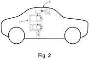
- a road vehicle 3 as illustrated in figure 2 , which has an apparatus 1 for situation dependent wheel angle ⁇ w control by a highly autonomous drive system 2 or an advanced driver assistance system 2, as described above with reference to figure 1 .
- the apparatus 1 of figure 1 e.g. arranged with an electrical power assisted steering system 40 as illustrated in figure 3
- the apparatus 1 of figure 1 may be arranged in a steering system 16 of the road vehicle 3 that comprises a steering wheel 21, connected to a steering rack 28 via a torsion bar 29, to which a steering wheel torque sensor 22 is arranged, and a pinion gear 30.
- the power steering control module 27 comprises the apparatus 1, which is arranged to control the overlay torque motor 15 of the steering system 16 of the road vehicle 3 to provide an overlay torque to steerable wheels 31 of the vehicle 3 steering system 16.
- a method for situation dependent wheel angle ⁇ w control by a highly autonomous drive system 2 or an advanced driver assistance system 2 of a road vehicle 3 the highly autonomous drive system 2 or advanced driver assistance system 2 being arranged to receive internal state data 10 from one or more road vehicle 3 internal state measurement units 11 and at least one of ambient information 6 on the road vehicle 3 surroundings from one or more road vehicle 3 surrounding monitoring cameras 7 and map data 8 relating to the road vehicle 3 surroundings from a road vehicle 3 localization system 9.
- the method is adapted for a road vehicle 3 comprising a lateral controller 4 arranged to receive from the highly autonomous drive system 2 or advanced driver assistance system 2 information on a desired path 5, and to output a wheel angle request ⁇ w,r .
- the method is further adapted for a road vehicle 3 having power steering control module 12 that comprises a wheel angle controller 13, where the wheel angle controller 13 is arranged to receive as inputs the wheel angle request ⁇ w,r from the lateral controller 4 as well as wheel angle ⁇ w and wheel angle rate ⁇ w data, and where the wheel angle controller 13 further is arranged to output an overlay torque request 14 suitable for a motor controller 15 of a steering system 16 of the road vehicle 3.
- the method starts out at 33, next at 34 is generated by the highly autonomous drive system 2 or advanced driver assistance system 2 a penalty measure 32 indicative of how penalties should be handled in the lateral controller 4 based on the internal state data 10 and at least one of the ambient information 6 and the map data 8.
- a penalty measure 32 indicative of how penalties should be handled in the lateral controller 4 based on the internal state data 10 and at least one of the ambient information 6 and the map data 8.
- gain parameters I ⁇ w , I ⁇ w are output to the wheel angle controller 13 at 36.
- the wheel angle controller 13 receives the calculated gain parameters I ⁇ w , I ⁇ w at 37, and uses them at 38 in control loops of the wheel angle controller 13, to increase the bandwidth of the wheel angle controller 13 if one or more of the ambient information 6, the map data 8 and the internal state data 10 indicate a need for increased control speed and accuracy for safely tracking the desired path 5, and to reduce the bandwidth of the wheel angle controller 13 if one or more of the ambient information 6, the map data 8 and the internal state data 10 indicate that decreased control speed and accuracy can be allowed whilst still safely tracking the desired path 5, whereupon the method at 39 loops back to start.
- a method as above provides for using high bandwidth in a wheel angle controller 13 in order for a desired path 5 to be tracked with increased control speed and accuracy when a traffic situation so requires, such as when free-space for safe maneuvers is limited, and reduced bandwidth in traffic situations allowing smooth and comfortable control for tracking the desired path 5 in traffic situations where there is more space for performing safe maneuvering.
Landscapes
- Engineering & Computer Science (AREA)
- Transportation (AREA)
- Mechanical Engineering (AREA)
- Chemical & Material Sciences (AREA)
- Combustion & Propulsion (AREA)
- Physics & Mathematics (AREA)
- General Physics & Mathematics (AREA)
- Radar, Positioning & Navigation (AREA)
- Automation & Control Theory (AREA)
- Aviation & Aerospace Engineering (AREA)
- Remote Sensing (AREA)
- Mathematical Physics (AREA)
- Computer Vision & Pattern Recognition (AREA)
- Multimedia (AREA)
- Electromagnetism (AREA)
- Steering Control In Accordance With Driving Conditions (AREA)
Abstract
Description
- The present application relates to an apparatus for situation dependent wheel angle control by a highly autonomous driving system or an advanced driver assistance system of a road vehicle and a method therefore.
- It is known to use power steering in road vehicles, e.g. electrical power assisted steering, commonly abbreviated as EPAS, in a road vehicle such as a car, lorry, bus or truck, wherein an electric motor assists a driver of the road vehicle by adding an assistive torque to e.g. a steering column or steering rack of the road vehicle.
- It is further known to use advanced driver assistance systems, commonly abbreviated as ADAS, such as Lane Keeping Aid systems, commonly abbreviated as LKA systems, in order to help a road vehicle driver maintain the road vehicle in a desired lane. For LKA or lane centering systems where an EPAS is used, a steering wheel torque overlay, i.e. additional steering wheel torque on top of what would have been obtained by the base assist of the EPAS, is used for lateral position control.
- However, the need for more advanced autonomous steering functions and also highly autonomous driving (HAD) has put new requirements on current steering safety concepts. One example of such a more advanced autonomous steering function is commonly called Pilot Assist, commonly abbreviated as PA, which helps a driver to drive the vehicle within the road lane whilst at the same time maintaining a preselected time interval to a preceding vehicle.
- Highly autonomous driving and advanced driver assistance systems, such as the above described Pilot Assist, adds a requirement of high bandwidth in the wheel angle controller in order for a HAD or PA path wheel/pinion angle request to be tracked fast and accurately.
- However, high bandwidth in the wheel angle controller may result in nervous and active steering wheel motions in situations where this behavior is undesirable, for example when driving on a wide lane or on a straight road. In addition to potentially causing discomfort to vehicle occupants this may also be perceived as control of the vehicle being erratic and nervous.
- Thus, there is a need for improved solutions which are able to comfortably, calmly and steadily, handle the above requirement for tracking of a HAD or PA path whilst facilitating fulfilment of high Automotive Safety Integrity requirements.
- Embodiments herein aim to provide an improved apparatus for situation dependent wheel angle control by a highly autonomous drive system or an advanced driver assistance system of a road vehicle the highly autonomous drive system or advanced driver assistance system being arranged to receive internal state data from one or more road vehicle internal state measurement units and at least one of ambient information on the road vehicle surroundings from one or more road vehicle surrounding monitoring cameras and map data relating to the road vehicle surroundings from a road vehicle localization system.
- This is provided through an apparatus comprising: a lateral controller arranged to receive from the highly autonomous drive system or advanced driver assistance system information on a desired path, and to output a wheel angle request; a power steering control module comprising a wheel angle controller arranged to receive as inputs the wheel angle request from the lateral controller as well as wheel angle and wheel angle rate data, and to output an overlay torque request suitable for a motor controller of a steering system of the road vehicle, wherein: the highly autonomous drive system or advanced driver assistance system is arranged to generate a penalty measure indicative of how penalties should be handled in the lateral controller based on the internal state data and at least one of the ambient information and the map data, and that the lateral controller further is arranged to calculate gain parameters, based on the penalty measure and to output to the wheel angle controller the calculated gain parameters; and that the wheel angle controller further is arranged to receive and use the gain parameters in control loops of the wheel angle controller, such that the bandwidth of the wheel angle controller is increased if one or more of the ambient information, the map data and the internal state data indicate a need for increased control speed and accuracy for safely tracking the desired path, and reduced if one or more of the ambient information, the map data and the internal state data indicate that decreased control speed and accuracy can be allowed whilst still safely tracking the desired path.
- The provision of using gain parameters in control loops of the wheel angle controller, as above, provides for using high bandwidth in a wheel angle controller in order for a desired path to be tracked with increased control speed and accuracy when a traffic situation so requires, such as when free-space for safe maneuvers is limited, and reduced bandwidth in traffic situations allowing less precise control, such as when driving on a wide lane or on a straight road with ample space for safe maneuvering.
- According to a second aspect is provided that the lateral controller further is arranged to calculate the gain parameters to provide for increased control speed and accuracy in tracking of the desired path if at least one of the ambient information, the map data and the internal state data indicate a reduced margin for safe road vehicle travel along the desired path.
- The provision of increased control speed and accuracy in tracking of the desired path if at least one of the ambient information, the map data and the internal state data indicate a reduced margin for safe road vehicle travel provides for a desired path to be tracked with high control speed and accuracy when a traffic situation so requires, such as when free-space for safe maneuvers is limited.
- According to a third aspect is provided that the lateral controller further is arranged to calculate the gain parameters to provide for decreased control speed and accuracy in tracking of the desired path if at least one of the ambient information, the map data and the internal state data indicate an increased margin for safe road vehicle travel along the desired path.
- The provision of decreased control speed and accuracy in tracking of the desired path if at least one of the ambient information, the map data and the internal state data indicate an increased margin for safe road vehicle travel provides for comfortable, calm and steady control when driving with ample space for safe maneuvering such as on a wide lane or on a straight road.
- According to a fourth aspect is provided that the wheel angle controller is arranged to execute a wheel angle control loop and a wheel angle rate control loop and that the lateral controller is arranged to calculate a gain parameter for the wheel angle control loop and a gain parameter for the wheel angle rate control loop of the wheel angle controller.
- The provision of using a gain parameter for the wheel angle control loop and a gain parameter for the wheel angle rate control loop, as above, enables recreation of a wheel angle rate request inside the power steering control module and improved tracking of the desired path.
- According to a fifth aspect is provided that the wheel angle controller is arranged to execute an outer wheel angle control loop and an inner wheel angle rate control loop and that the lateral controller is arranged to calculate a gain parameter for the outer wheel angle control loop and a gain parameter for the inner wheel angle rate control loop of the wheel angle controller.
- The provision of using a gain parameter for the outer wheel angle control loop and a gain parameter for the inner wheel angle rate control loop, as above, enables recreation of a wheel angle rate request inside the power steering control module and further improved tracking of the desired path.
- According to a sixth aspect is provided that the lateral controller has a linear quadratic problem formulation with a quadratic penalty on wheel angle rate and wheel angle acceleration and the linear quadratic problem formulation is used to calculate the gain parameters.
- The provision of using the linear quadratic problem formulation, as above, to calculate the gain parameters provides an efficient way to provide gain parameters enabling recreation in the power steering control module of a wheel angle rate request in an active safety domain master of the advanced driver assistance system.
- According to a seventh aspect is provided that the power steering control module is arranged to recreate a wheel angle rate request for the wheel angle rate control loop of the wheel angle controller from the gain parameter for the wheel angle control loop and the gain parameter for the wheel angle rate control loop, the wheel angle request, the wheel angle and the wheel angle rate data.
- The provision of recreating a wheel angle rate request, as above, provides a simple and reliable way of ensuring improved control by the wheel angle controller.
- According to an eight aspect is provided that the power steering control module is arranged to recreate the wheel angle rate request for the wheel angle rate control loop of the wheel angle controller as the gain parameter for the wheel angle control loop multiplied with the difference between the wheel angle request and the wheel angle reduced with the product of the gain parameter for the wheel angle rate control loop and the wheel angle rate data.
- The provision of recreating a wheel angle rate request, as above, provides a simple and reliable way of ensuring further improved control by the wheel angle controller.
- According to a ninth aspect is provided a steer torque manager that comprises a wheel angle controller arranged to receive and use gain parameters, as above, in control loops of the wheel angle controller.
- The provision of a steer torque manager, as above, provides for using high bandwidth in a wheel angle controller in order for a desired path to be tracked with increased control speed and accuracy when a traffic situation so requires, such as when free-space for safe maneuvers is limited, and reduced bandwidth in traffic situations allowing less precise control, such as when driving on a wide lane or on a straight road with ample space for safe maneuvering.
- According to a tenth aspect is provided a road vehicle that comprises an apparatus as above.
- The provision of a road vehicle that comprises an apparatus as above provides for using high bandwidth in a wheel angle controller in order for a desired path to be tracked with increased control speed and accuracy when a traffic situation so requires, such as when free-space for safe maneuvers is limited, and reduced bandwidth in traffic situations allowing less precise control, such as when driving on a wide lane or on a straight road with ample space for safe maneuvering.
- According to an eleventh aspect is provided a method for situation dependent wheel angle control by a highly autonomous drive system or an advanced driver assistance system of a road vehicle, the highly autonomous drive system or advanced driver assistance system being arranged to receive internal state data from one or more road vehicle internal state measurement units and at least one of ambient information on the road vehicle surroundings from one or more road vehicle surrounding monitoring cameras and map data relating to the road vehicle surroundings from a road vehicle localization system, the road vehicle comprising: a lateral controller arranged to receive from the highly autonomous drive system or advanced driver assistance system information on a desired path, and to output a wheel angle request; a power steering control module comprising a wheel angle controller arranged to receive as inputs the wheel angle request from the lateral controller as well as wheel angle and wheel angle rate data, and to output an overlay torque request suitable for a motor controller of a steering system of the road vehicle, which method comprises: generating, by the highly autonomous drive system or advanced driver assistance system a penalty measure indicative of how penalties should be handled in the lateral controller based on the internal state data and at least one of the ambient information and the map data, and calculating in the lateral controller gain parameters, based on the penalty measure, and outputting to the wheel angle controller the calculated gain parameters; receiving to the wheel angle controller the gain parameters and using them in control loops of the wheel angle controller, to increase the bandwidth of the wheel angle controller if one or more of the ambient information, the map data and the internal state data indicate a need for increased control speed and accuracy for safely tracking the desired path, and to reduce the bandwidth of the wheel angle controller if one or more of the ambient information, the map data and the internal state data indicate that decreased control speed and accuracy can be allowed whilst still safely tracking the desired path.
- A method as above provides for using high bandwidth in a wheel angle controller in order for a desired path to be tracked with increased control speed and accuracy when a traffic situation so requires, such as when free-space for safe maneuvers is limited, and reduced bandwidth in traffic situations allowing less precise control, such as when driving on a wide lane or on a straight road with ample space for safe maneuvering.
- In the following, embodiments herein will be described in greater detail by way of example only with reference to attached drawings, in which
-
Fig. 1 is a schematic illustration of an apparatus for situation dependent wheel angle control by an advanced driver assistance system of a road vehicle. -
Fig. 2 is a schematic illustration of a road vehicle comprising an apparatus for situation dependent wheel angle control according tofigure 1 . -
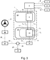
Fig. 3 is a schematic illustration of a road vehicle steering system comprising the apparatus offigure 1 arranged with an electrical power assisted steering system thereof. -
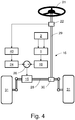
Fig. 4 is a schematic illustration of theapparatus 1 offigure 1 , arranged with an electrical power assisted steering system as illustrated infigure 3 . -
Fig. 5 is a schematic illustration of a method for situation dependent wheel angle control by an advanced driver assistance system of a road vehicle according to embodiments herein. - Still other objects and features of embodiments herein will become apparent from the following detailed description considered in conjunction with the accompanying drawings. It is to be understood, however, that the drawings are designed solely for purposes of illustration and not as a definition of the limits hereof, for which reference should be made to the appended claims. It should be further understood that the drawings are not necessarily drawn to scale and that, unless otherwise indicated, they are merely intended to conceptually illustrate the structures and procedures described herein.
- This disclosure is based on the realization that it should be possible to provide an improved apparatus for tracking a path requested by a highly autonomous drive system (HAD) or an advanced driver assistance system (ADAS) of a road vehicle such that the accuracy and responsiveness can be improved if a traffic situation so requires, e.g. if there is less space for performing safe maneuvering when tracking the desired path. This, whilst at the same time being able to provide for smooth and comfortable control for tracking the desired path in situations where there is more space for performing safe maneuvering. As described in the following it is thus suggested to alter closed loop wheel angle dynamics as a road vehicle enters new traffic situations and environments. Such a path is usually requested through the highly autonomous drive system or an advanced driver assistance system continuously issuing wheel/pinion angle requests.
- This is, as illustrated in
figure 1 , provided through anapparatus 1 for situation dependent wheel angle δ w control by a highlyautonomous drive system 2 or an advanceddriver assistance system 2 of aroad vehicle 3, as described in the following. Theapparatus 1 is suitable for use with a highlyautonomous drive system 2 or an advanceddriver assistance system 2 of aroad vehicle 3 having an electrical power assisted steering (EPAS) 40. The highlyautonomous drive system 2 or advanceddriver assistance system 2 of theroad vehicle 3 having situation awareness through being arranged to receiveinternal state data 10 from one ormore road vehicle 3 internalstate measurement units 11 and at least one ofambient information 6 on theroad vehicle 3 surroundings from one ormore road vehicle 3 surroundingmonitoring cameras 7 andmap data 8 relating to theroad vehicle 3 surroundings from aroad vehicle 3localization system 9, such as e.g. a GPS based navigational system. -
Figure 1 illustrates theapparatus 1 schematically. Alateral controller 4, arranged in adomain 20 outside of a power steering control module (PSCM) 12, is arranged to receive, from the highlyautonomous drive system 2 or advanceddriver assistance system 2, information on a desiredpath 5. Thelateral controller 4 is further arranged to output a wheel angle request δw,r (index r for request). - The power
steering control module 12 comprises awheel angle controller 13. Thewheel angle controller 13 is arranged to receive as inputs the wheel angle request δ w,r from thelateral controller 4 as well as wheel angle δ w and wheel angle rate δ̇ w data from one or more sensors (not shown) of theroad vehicle 3 steering system. - The
wheel angle controller 13 is further arranged to output anoverlay torque request 14 suitable for amotor controller 15 of asteering system 16 of theroad vehicle 3. - The
overlay torque request 14 can be identified as a QM hazard which does not dictate any safety requirements, why it is subject to an overlaytorque safety limiter 18 which provides a safety limitedoverlay torque request 19 that fulfil Automotive Safety Integrity Level D, which is the highest classification of initial hazard (injury risk) defined within ISO 26262 and to that standard's most stringent level of safety measures to apply for avoiding an unreasonable residual risk. - The highly
autonomous drive system 2 or advanceddriver assistance system 2 is arranged to generate apenalty measure 32 indicative of how penalties should be handled in thelateral controller 4 based on theinternal state data 10 and at least one of theambient information 6 and themap data 8. - The
lateral controller 4 is further arranged to calculate gain parameters I δ w , I δ̇w , based on thepenalty measure 32, and to output to thewheel angle controller 13 the calculated gain parameters I δ w , Iδ̇w . - Thus, the calculated gain parameters I δ w , I δ̇
w are continuously sent to thewheel angle controller 13 of the powersteering control module 12, which makes it possible to alter closed loop wheel angle dynamics as theroad vehicle 3 enters new traffic situations and environments, as will be elaborated in the following. - The
wheel angle controller 13 is further arranged to receive and use the gain parameters I δ w , I δ̇w in control loops of thewheel angle controller 13. The gain parameters I δ w , Iδ̇w are used in the control loops such that the bandwidth of thewheel angle controller 13 is increased if one or more of theambient information 6, themap data 8 and theinternal state data 10 indicate a need for increased control speed and accuracy for safely tracking the desiredpath 5, and reduced if one or more of theambient information 6, themap data 8 and theinternal state data 10 indicate that decreased control speed and accuracy can be allowed whilst still safely tracking the desiredpath 5. - The above provides for using high bandwidth in the
wheel angle controller 13 in order for the desiredpath 5 to be tracked with increased accuracy and responsiveness when a traffic situation so requires, such as when free-space for safe maneuvers around theroad vehicle 3 is limited, e.g. if theroad vehicle 3 is passing a large truck, driving in a narrow lane or if a forward vehicle is cutting in ahead of theroad vehicle 3. It further provides for using reduced bandwidth in traffic situations allowing to provide for slightly less precise and responsive and therefore more smooth and comfortable control for tracking the desiredpath 5 in situations where there is more space for performing safe maneuvering, such as when driving on a wide lane or on a straight road with ample space for safe maneuvering. - The
ambient information 6 andmap data 8 provides for situation awareness, which is normally not available in the powersteering control module 12. Moreover, it is not possible to move wheel angle control loops of thewheel angle controller 13 outside the powersteering control module 12 due to the communication delays that would result therefrom. The above solution is thus more or less insensitive to time delays between thelateral controller 4 and the powersteering control module 12 since thelateral controller 4 will not require any information on the current state of the powersteering control module 12. - In consequence, in some embodiments the
lateral controller 4 is further arranged to calculate the gain parameters I δ w , I δ̇w to provide for increased control speed and accuracy in tracking of the desiredpath 5 if at least one of theambient information 6, themap data 8 and theinternal state data 10 indicate a reduced margin forsafe road vehicle 3 travel along the desiredpath 5. - And conversely, in some embodiments the
lateral controller 4 is further arranged to calculate the gain parameters I δ w , I δ̇w to provide for decreased control speed and accuracy in tracking of the desiredpath 5 if at least one of theambient information 6, themap data 8 and theinternal state data 10 indicate an increased margin forsafe road vehicle 3 travel along the desiredpath 5. - The term margin for
safe road vehicle 3 travel along the desiredpath 5 is here meant to encompass physical margins forunobstructed road vehicle 3 travel, such as distances to surrounding infrastructure and vehicles, allowable velocities and acceleration with respect to surrounding traffic etc.. - These embodiments provides for a desired
path 5 to be tracked with increased accuracy and responsiveness when a traffic situation so requires, such as when free-space for safe maneuvers is limited as well as for comfortable, calm and steady control when driving with ample space for safe maneuvering, such as on a wide lane or on a straight road. - In further embodiments the
wheel angle controller 13 is arranged to execute a wheel angle control loop and a wheel angle rate control loop and thelateral controller 4 is arranged to calculate a gain parameter I δ w for the wheel angle control loop and a gain parameter I δ̇w for the wheel angle rate control loop of thewheel angle controller 13. - This enables recreation of a wheel angle rate request δ̇w,r inside the power
steering control module 12, as will be described in more detail in the following, and further provides for improved tracking of the desiredpath 5. - In order to provide for further improved tracking of the desired
path 5, in a further embodiment thewheel angle controller 13 is arranged to execute an outer wheel angle control loop and an inner wheel angle rate control loop and that thelateral controller 4 is arranged to calculate a gain parameter I δ w,o for the outer wheel angle control loop (index o for outer) and a gain parameter I δ̇w,i for the inner wheel angle rate control loop (index i for inner) of thewheel angle controller 13. - For embodiments herein it is envisaged that the
lateral controller 4 has a linear quadratic problem formulation with a quadratic penalty on wheel angle rate δ̇ w and wheel angle acceleration δ̈ w and the linear quadratic problem formulation is used to calculate the gain parameters I δ w, I δ w,o , I δ̇w , I δ̇w,i . This as it in the linear quadratic problem formulation is natural to consider the wheel angle rate δ̇ w as the control signal, which means that the linear quadratic problem will decide the gains used in the wheel angle δ w control loop. Thus, this provides an efficient way to provide gain parameters I δ w , I δ w,o , I δ̇w , I δ̇w,i enabling recreation in the powersteering control module 12 of a wheel angle rate request δ̇ w,r in an active safety domain master of the highlyautonomous drive system 2 or advanceddriver assistance system 2. - As mentioned above, in some further embodiments the power
steering control module 12 is arranged to recreate a wheel angle rate request δ̇ w,r for the wheel angle rate control loop of thewheel angle controller 13 from the gain parameter I δ w , I δ w,o for the wheel angle control loop and the gain parameter I δ̇w , I δ̇w,i for the wheel angle rate control loop, the wheel angle request δ w,r , the wheel angle δ w and the wheel angle rate data δ̇w. This provides a simple and reliable way of ensuring improved control by thewheel angle controller 13. - More particularly, in some embodiments this is achieved through the power
steering control module 12 being arranged to recreate the wheel angle rate request δ̇ w,r for the wheel angle rate control loop of thewheel angle controller 13 as the gain parameter for the wheel angle control loop I δ w , I δ w,o multiplied with the difference between the wheel angle request δw,r and the wheel angle δ w reduced with the product of the gain parameter for the wheel angle rate control loop I δ̇w , I δ̇w,i and the wheel angle rate data δ̇ w . - I.e. as

- It is further envisaged herein a
steer torque manager 17, that comprises awheel angle controller 13 arranged to receive and use the gain parameters I δ w , I δ̇w in control loops of thewheel angle controller 13, as described above. A steer torque manager, commonly abbreviated as STM, is a component that is commonly located in an EPAS supplier node, herein referred to as Power Steering Control Module, commonly abbreviated as PSCM.Figure 3 is a schematic illustration of a road vehicle steering system comprising the apparatus offigure 1 arranged with an electrical power assistedsteering system 40 thereof. - As illustrated schematically in
figure 3 , the apparatus offigure 1 may be arranged with an electrical power assistedsteering system 40 of aroad vehicle 3. In such an arrangement thesteer torque manager 17, may further be arranged such that asteering wheel 21 torque applied by a driver of theroad vehicle 3, is sensed by a steeringwheel torque sensor 22 and used by an electrical power assisted steering (EPAS)assistance functionality 40 to provide anassistance torque request 23, for assisting a driver when during manual or semi-automated steering control of theroad vehicle 3. Such anassistance torque request 23 is normally also identified as a OM hazard which does not dictate any safety requirements according to the Automotive Safety Integrity Level (ASIL) risk classification scheme defined by the ISO 26262 - Functional Safety for Road Vehicles standard, and is therefore normally also subject to an assistancetorque safety limiter 24 which in turn provide a safety limitedassistance torque request 25 which is then suitably brought to asummation point 26 to be added to the safety limitedoverlay torque request 19, and which summation point in turn provides atotal torque request 27 to themotor controller 15 of the steering system of theroad vehicle 3. - Still further envisaged herein is a
road vehicle 3, as illustrated infigure 2 , which has anapparatus 1 for situation dependent wheel angle δ w control by a highlyautonomous drive system 2 or an advanceddriver assistance system 2, as described above with reference tofigure 1 . - A
road vehicle 2 that has a highlyautonomous drive system 2 or an advanceddriver assistance system 2 that comprises anapparatus 1, as described above, provides for improved safety and driver comfort when using a highlyautonomous drive system 2 or an advanceddriver assistance system 2, such as a pilot assist system. - As illustrated schematically in
figure 4 , theapparatus 1 offigure 1 , e.g. arranged with an electrical power assistedsteering system 40 as illustrated infigure 3 , may be arranged in asteering system 16 of theroad vehicle 3 that comprises asteering wheel 21, connected to asteering rack 28 via atorsion bar 29, to which a steeringwheel torque sensor 22 is arranged, and apinion gear 30. The powersteering control module 27 comprises theapparatus 1, which is arranged to control theoverlay torque motor 15 of thesteering system 16 of theroad vehicle 3 to provide an overlay torque tosteerable wheels 31 of thevehicle 3steering system 16. - In accordance with the present application is also envisaged a method for situation dependent wheel angle δ w control by a highly
autonomous drive system 2 or an advanceddriver assistance system 2 of aroad vehicle 3, the highlyautonomous drive system 2 or advanceddriver assistance system 2 being arranged to receiveinternal state data 10 from one ormore road vehicle 3 internalstate measurement units 11 and at least one ofambient information 6 on theroad vehicle 3 surroundings from one ormore road vehicle 3 surroundingmonitoring cameras 7 andmap data 8 relating to theroad vehicle 3 surroundings from aroad vehicle 3localization system 9. - The method is adapted for a
road vehicle 3 comprising alateral controller 4 arranged to receive from the highlyautonomous drive system 2 or advanceddriver assistance system 2 information on a desiredpath 5, and to output a wheel angle request δ w,r . - The method is further adapted for a
road vehicle 3 having powersteering control module 12 that comprises awheel angle controller 13, where thewheel angle controller 13 is arranged to receive as inputs the wheel angle request δ w,r from thelateral controller 4 as well as wheel angle δ w and wheel angle rate δ̇ w data, and where thewheel angle controller 13 further is arranged to output anoverlay torque request 14 suitable for amotor controller 15 of asteering system 16 of theroad vehicle 3. - As schematically illustrated in
figure 5 the method starts out at 33, next at 34 is generated by the highlyautonomous drive system 2 or advanced driver assistance system 2 apenalty measure 32 indicative of how penalties should be handled in thelateral controller 4 based on theinternal state data 10 and at least one of theambient information 6 and themap data 8. At 35 is calculated in thelateral controller 4 gain parameters I δ w , I δ̇w , based on the penalty measure (32). The calculated gain parameters I δ w , I δ̇w are output to thewheel angle controller 13 at 36. Thewheel angle controller 13 receives the calculated gain parameters I δ w , I δ̇w at 37, and uses them at 38 in control loops of thewheel angle controller 13, to increase the bandwidth of thewheel angle controller 13 if one or more of theambient information 6, themap data 8 and theinternal state data 10 indicate a need for increased control speed and accuracy for safely tracking the desiredpath 5, and to reduce the bandwidth of thewheel angle controller 13 if one or more of theambient information 6, themap data 8 and theinternal state data 10 indicate that decreased control speed and accuracy can be allowed whilst still safely tracking the desiredpath 5, whereupon the method at 39 loops back to start. - A method as above provides for using high bandwidth in a
wheel angle controller 13 in order for a desiredpath 5 to be tracked with increased control speed and accuracy when a traffic situation so requires, such as when free-space for safe maneuvers is limited, and reduced bandwidth in traffic situations allowing smooth and comfortable control for tracking the desiredpath 5 in traffic situations where there is more space for performing safe maneuvering. - The above-described embodiments may be varied within the scope of the following claims.
- Thus, while there have been shown and described and pointed out fundamental novel features of the embodiments herein, it will be understood that various omissions and substitutions and changes in the form and details of the devices illustrated, and in their operation, may be made by those skilled in the art. For example, it is expressly intended that all combinations of those elements and/or method steps which perform substantially the same function in substantially the same way to achieve the same results are equivalent. Moreover, it should be recognized that structures and/or elements and/or method steps shown and/or described in connection with any disclosed form or embodiment herein may be incorporated in any other disclosed or described or suggested form or embodiment as a general matter of design choice.
Claims (11)
- An apparatus (1) for situation dependent wheel angle (δ w ) control by a highly autonomous drive system (2) or an advanced driver assistance system (2) of a road vehicle (3), the highly autonomous drive system (2) or advanced driver assistance system (2) being arranged to receive internal state data (10) from one or more road vehicle (3) internal state measurement units (11) and at least one of ambient information (6) on the road vehicle (3) surroundings from one or more road vehicle (3) surrounding monitoring cameras (7) and map data (8) relating to the road vehicle (3) surroundings from a road vehicle (3) localization system (9), the apparatus (1) comprising: a lateral controller (4) arranged to receive from the highly autonomous drive system (2) or advanced driver assistance system (2) information on a desired path (5), and to output a wheel angle request (δ w,r ); a power steering control module (12) comprising a wheel angle controller (13) arranged to receive as inputs the wheel angle request (δ w,r ) from the lateral controller (4) as well as wheel angle (δ w ) and wheel angle rate (δ̇ w ) data, and to output an overlay torque request (14) suitable for a motor controller (15) of a steering system (16) of the road vehicle (3), characterized in that: the highly autonomous drive system (2) or advanced driver assistance system (2) is arranged to generate a penalty measure (32) indicative of how penalties should be handled in the lateral controller (4) based on the internal state data (10) and at least one of the ambient information (6) and the map data (8) and,
that the lateral controller (4) further is arranged to calculate gain parameters (Iδw , I δ̇w ), based on the penalty measure (32) and to output to the wheel angle controller (13) the calculated gain parameters (I δw , I δ̇w ); and that the wheel angle controller (13) further is arranged to receive and use the gain parameters (I δ w , I δ̇w ) in control loops of the wheel angle controller (13), such that the bandwidth of the wheel angle controller (13) is increased if one or more of the ambient information (6), the map data (8) and the internal state data (10) indicate a need for increased control speed and accuracy for safely tracking the desired path (5), and reduced if one or more of the ambient information (6), the map data (8) and the internal state data (10) indicate that decreased control speed and accuracy can be allowed whilst still safely tracking the desired path (5). - An apparatus (1) according to claim 1, characterized in that the lateral controller (4) further is arranged to calculate the gain parameters (I δ w , I δ̇
w ) to provide for increased control speed and accuracy in tracking of the desired path (5) if at least one of the ambient information (6), the map data (8) and the internal state data (10) indicate a reduced margin for safe road vehicle (3) travel along the desired path (5). - An apparatus (1) according claim 1, characterized in that the lateral controller (4) further is arranged to calculate the gain parameters (I δ w , I δ̇
w ) to provide for decreased control speed and accuracy in tracking of the desired path (5) if at least one of the ambient information (6), the map data (8) and the internal state data (10) indicate an increased margin for safe road vehicle (3) travel along the desired path (5). - An apparatus (1) according to any one of claims 1-3, characterized in that the wheel angle controller (13) is arranged to execute a wheel angle control loop and a wheel angle rate control loop and that the lateral controller (4) is arranged to calculate a gain parameter (I δ w ) for the wheel angle control loop and a gain parameter (I δ̇
w ) for the wheel angle rate control loop of the wheel angle controller (13). - An apparatus (1) according to any one of claims 1-3, characterized in that the wheel angle controller (13) is arranged to execute an outer wheel angle control loop and an inner wheel angle rate control loop and that the lateral controller (4) is arranged to calculate a gain parameter (I δ w,o ) for the outer wheel angle control loop and a gain parameter (I δ̇
w,i ) for the inner wheel angle rate control loop of the wheel angle controller (13). - An apparatus (1) according to any one of claims 1-5, characterized in that the lateral controller (4) has a linear quadratic problem formulation with a quadratic penalty on wheel angle rate (δw ) and wheel angle acceleration (δ̈ w ) and the linear quadratic problem formulation is used to calculate the gain parameters (I δw, I δ w,o , I δ̇
w , I δ̇w,i ). - An apparatus (1) according to any one of claims 1-6, characterized in that the power steering control module (12) is arranged to recreate a wheel angle rate request (δ̇ w,r ) for the wheel angle rate control loop of the wheel angle controller (13) from the gain parameter for the wheel angle control loop (I δ w , Iδ w,o ) and the gain parameter for the wheel angle rate control loop (I δ̇
w , Iδ̇w,i ), the wheel angle request (δ w,r ), the wheel angle (δ w ) and the wheel angle rate data (δ̇ w ). - An apparatus (1) according to claim 7, characterized in that the power steering control module (12) is arranged to recreate the wheel angle rate request (δ̇ w,r ) for the wheel angle rate control loop of the wheel angle controller (13) as the gain parameter for the wheel angle control loop (I δ w , Iδ w,o ) multiplied with the difference between the wheel angle request (δ w,r ) and the wheel angle (δ w ) reduced with the product of the gain parameter for the wheel angle rate control loop (I δ̇
w , Iδ̇w,i ) and the wheel angle rate data (δ̇ w ). - A steer torque manager (17), characterized in that it comprises a wheel angle controller (13) arranged to receive and use gain parameters (I δ w , I δ̇
w ) according to any one of claims 1-8 in control loops of the wheel angle controller (13). - A road vehicle (3), characterized in that it comprises an apparatus according to any one of claims 1-8.
- A method for situation dependent wheel angle (δ w ) control by a highly autonomous drive system (2) or an advanced driver assistance system (2) of a road vehicle (3), the highly autonomous drive system (2) or advanced driver assistance system (2) being arranged to receive internal state data (10) from one or more road vehicle (3) internal state measurement units (11) and at least one of ambient information (6) on the road vehicle (3) surroundings from one or more road vehicle (3) surrounding monitoring cameras (7) and map data (8) relating to the road vehicle (3) surroundings from a road vehicle (3) localization system (9), the road vehicle (3) comprising: a lateral controller (4) arranged to receive from the highly autonomous drive system (2) or advanced driver assistance system (2) information on a desired path (5), and to output a wheel angle request (δ w,r ); a power steering control module (12) comprising a wheel angle controller (13) arranged to receive as inputs the wheel angle request (δ w,r ) from the lateral controller (4) as well as wheel angle (δ w ) and wheel angle rate (δ̇ w ) data, and to output an overlay torque request (14) suitable for a motor controller (15) of a steering system (16) of the road vehicle (3), characterized in that it comprises:generating, by the highly autonomous drive system (2) or advanced driver assistance system (2) a penalty measure (32) indicative of how penalties should be handled in the lateral controller (4) based on the internal state data (10) and at least one of the ambient information (6) and the map data (8), andcalculating in the lateral controller (4) gain parameters (I δ
w , I δ̇w ), based on the penalty measure (32), and outputting to the wheel angle controller (13) the calculated gain parameters (I δ w , I δ̇w );receiving to the wheel angle controller (13) the gain parameters (I δ w , I δ̇w ) and using them in control loops of the wheel angle controller (13), to increase the bandwidth of the wheel angle controller (13) if one or more of the ambient information (6), the map data (8) and the internal state data (10) indicate a need for increased control speed and accuracy for safely tracking the desired path (5), and to reduce the bandwidth of the wheel angle controller (13) if one or more of the ambient information (6), the map data (8) and the internal state data (10) indicate that decreased control speed and accuracy can be allowed whilst still safely tracking the desired path (5).
Priority Applications (3)
| Application Number | Priority Date | Filing Date | Title |
|---|---|---|---|
| EP17161795.4A EP3378733B1 (en) | 2017-03-20 | 2017-03-20 | Apparatus and method for situation dependent wheel angle control (had or adas) |
| CN201810199002.6A CN108622183B (en) | 2017-03-20 | 2018-03-12 | Apparatus and method for condition dependent HAD or ADAS wheel steering controller |
| US15/920,019 US10640145B2 (en) | 2017-03-20 | 2018-03-13 | Apparatus and method for situation dependent had or ADAS wheel angle control |
Applications Claiming Priority (1)
| Application Number | Priority Date | Filing Date | Title |
|---|---|---|---|
| EP17161795.4A EP3378733B1 (en) | 2017-03-20 | 2017-03-20 | Apparatus and method for situation dependent wheel angle control (had or adas) |
Publications (2)
| Publication Number | Publication Date |
|---|---|
| EP3378733A1 true EP3378733A1 (en) | 2018-09-26 |
| EP3378733B1 EP3378733B1 (en) | 2020-01-15 |
Family
ID=58387731
Family Applications (1)
| Application Number | Title | Priority Date | Filing Date |
|---|---|---|---|
| EP17161795.4A Active EP3378733B1 (en) | 2017-03-20 | 2017-03-20 | Apparatus and method for situation dependent wheel angle control (had or adas) |
Country Status (3)
| Country | Link |
|---|---|
| US (1) | US10640145B2 (en) |
| EP (1) | EP3378733B1 (en) |
| CN (1) | CN108622183B (en) |
Families Citing this family (10)
| Publication number | Priority date | Publication date | Assignee | Title |
|---|---|---|---|---|
| EP3360757B1 (en) | 2017-02-10 | 2019-10-02 | Volvo Car Corporation | Steer torque manager for an advanced driver assistance system of a road vehicle |
| EP3375696B1 (en) | 2017-03-17 | 2019-11-20 | Volvo Car Corporation | Steer torque manager for an advanced driver assistance system of a road vehicle |
| US10282998B2 (en) * | 2017-03-17 | 2019-05-07 | Denso International America, Inc. | Vehicle system and vehicle controller for controlling vehicle |
| EP3378731B1 (en) | 2017-03-20 | 2020-01-15 | Volvo Car Corporation | Apparatus and method for driver activity dependent (adas) wheel angle controller |
| DE102017207391B4 (en) * | 2017-05-03 | 2019-02-28 | Ford Global Technologies, Llc | A method for generating a resulting auxiliary steering torque adapted to a current driving situation of a vehicle using an active steering assistance system and steering assistance system |
| CN110884563A (en) * | 2019-12-12 | 2020-03-17 | 上海衡鲁汽车科技有限公司 | An electric power-assisted advanced driver assistance system |
| US12555485B2 (en) * | 2020-11-26 | 2026-02-17 | Bae Systems Plc | Autonomous taxiing method and apparatus |
| US11999417B2 (en) * | 2021-11-29 | 2024-06-04 | Volvo Car Corporation | Steering angle control using haptic controller |
| CN117037473B (en) * | 2023-07-27 | 2026-03-27 | 南斗六星(武汉)技术有限公司 | A lane-based method for correcting the direction of vehicle front view |
| CN119590508A (en) * | 2024-12-31 | 2025-03-11 | 广州市柏琳汽车零件制造有限公司 | Steering assistance system for new energy vehicles |
Citations (2)
| Publication number | Priority date | Publication date | Assignee | Title |
|---|---|---|---|---|
| US20080047775A1 (en) * | 2006-08-28 | 2008-02-28 | Toyota Jidosha Kabushiki Kaisha | Electric power steering device, and control method thereof |
| EP2159777A2 (en) * | 2008-05-30 | 2010-03-03 | Navteq North America, LLC | Data mining to identify locations of potentially hazardous conditions for vehicle operation and use thereof |
Family Cites Families (60)
| Publication number | Priority date | Publication date | Assignee | Title |
|---|---|---|---|---|
| JP2671626B2 (en) * | 1991-04-08 | 1997-10-29 | 日産自動車株式会社 | Driving information provision device |
| GB9317983D0 (en) | 1993-08-28 | 1993-10-13 | Lucas Ind Plc | A driver assistance system for a vehicle |
| US6053270A (en) | 1995-11-02 | 2000-04-25 | Honda Giken Kogyo Kabushiki Kaisha | Steering angle correcting system in vehicle |
| JP3647538B2 (en) * | 1996-02-12 | 2005-05-11 | 本田技研工業株式会社 | Vehicle steering device |
| JP3314866B2 (en) | 1997-09-13 | 2002-08-19 | 本田技研工業株式会社 | Vehicle steering system |
| JP2001256598A (en) * | 2000-03-08 | 2001-09-21 | Honda Motor Co Ltd | Danger spot notification system |
| US8280533B2 (en) * | 2000-06-20 | 2012-10-02 | Fisher-Rosemount Systems, Inc. | Continuously scheduled model parameter based adaptive controller |
| KR20020094545A (en) | 2001-06-12 | 2002-12-18 | 현대자동차주식회사 | A method for controlling a vehicle to be kept in a lane and a method thereof |
| JP3866532B2 (en) * | 2001-06-13 | 2007-01-10 | 富士通株式会社 | Mobile object safe operation support apparatus and computer program |
| JP3585874B2 (en) | 2001-09-04 | 2004-11-04 | 本田技研工業株式会社 | Vehicle travel control device |
| US6879896B2 (en) | 2002-04-11 | 2005-04-12 | Delphi Technologies, Inc. | System and method for using vehicle operator intent to adjust vehicle control system response |
| US7499949B2 (en) * | 2002-08-07 | 2009-03-03 | Navteq North America, Llc | Method and system for obtaining recurring delay data using navigation systems |
| US7510038B2 (en) | 2003-06-11 | 2009-03-31 | Delphi Technologies, Inc. | Steering system with lane keeping integration |
| WO2005003885A2 (en) * | 2003-07-07 | 2005-01-13 | Sensomatix Ltd. | Traffic information system |
| JP4161938B2 (en) * | 2004-06-01 | 2008-10-08 | トヨタ自動車株式会社 | Travel control device |
| US7664584B2 (en) * | 2005-03-01 | 2010-02-16 | Nissan Motor Co., Ltd. | Steering control system |
| AU2006306523B2 (en) | 2005-10-21 | 2011-05-19 | Deere & Company | Systems and methods for switching between autonomous and manual operation of a vehicle |
| JP4449960B2 (en) | 2006-08-22 | 2010-04-14 | トヨタ自動車株式会社 | Steering support device |
| DE602008004435D1 (en) | 2008-04-02 | 2011-02-24 | Gm Global Tech Operations Inc | Adaptive steering control for a motor vehicle |
| US8392064B2 (en) | 2008-05-27 | 2013-03-05 | The Board Of Trustees Of The Leland Stanford Junior University | Systems, methods and devices for adaptive steering control of automotive vehicles |
| US8170751B2 (en) | 2008-12-17 | 2012-05-01 | GM Global Technology Operations LLC | Detection of driver intervention during a torque overlay operation in an electric power steering system |
| EP2427356B1 (en) * | 2009-05-07 | 2017-04-12 | Continental Teves AG & Co. oHG | Method and apparatus for regulating or controlling the driving stability of a vehicle |
| EP2448806B1 (en) | 2009-06-29 | 2015-04-22 | Volvo Lastvagnar AB | A method and a system for assisting a driver of a vehicle during operation |
| JP5540092B2 (en) | 2009-06-29 | 2014-07-02 | ボルボ ラストバグナー アーベー | Method and system for changing the trajectory of a vehicle |
| US8270605B2 (en) * | 2009-09-01 | 2012-09-18 | Sony Corporation | Location authentication |
| WO2011111121A1 (en) * | 2010-03-12 | 2011-09-15 | トヨタ自動車株式会社 | Steering support device |
| JP5429062B2 (en) * | 2010-06-11 | 2014-02-26 | トヨタ自動車株式会社 | Vehicle travel control device |
| US8977419B2 (en) * | 2010-12-23 | 2015-03-10 | GM Global Technology Operations LLC | Driving-based lane offset control for lane centering |
| DE102012001666A1 (en) | 2012-01-28 | 2013-08-01 | Audi Ag | Method for steering a vehicle by means of a steering assistance system |
| DE102013213216A1 (en) * | 2013-07-05 | 2015-01-08 | Robert Bosch Gmbh | Method and apparatus for assisting a driver of a vehicle in a bottleneck |
| EP3057848B1 (en) * | 2013-10-16 | 2018-04-11 | Sentient AB | Method in order to control vehicle behaviour |
| JP5988308B2 (en) * | 2013-12-27 | 2016-09-07 | 富士重工業株式会社 | Vehicle lane keeping control device |
| JP6378887B2 (en) | 2014-02-04 | 2018-08-22 | Kyb株式会社 | Electric power steering device |
| JP2015231825A (en) * | 2014-05-13 | 2015-12-24 | トヨタ自動車株式会社 | Vehicle travel control device |
| EP2949548B1 (en) * | 2014-05-27 | 2018-07-11 | Volvo Car Corporation | Lane keeping suppressing system and method |
| FR3022515B1 (en) * | 2014-06-24 | 2016-07-29 | Jtekt Europe Sas | MIXED STEERING ASSISTANCE COMPRISING A TORQUE CONTROL LOOP PILOTED WITH A POSITION CONTROLLER INTENDED FOR TRACK ENTRY |
| US9821837B2 (en) * | 2014-07-31 | 2017-11-21 | Nsk Ltd. | Electric power steering apparatus |
| FR3026708B1 (en) * | 2014-10-07 | 2016-11-18 | Jtekt Europe Sas | SECURING DRIVING ASSISTANCE FUNCTION WITHIN AN ASSISTED STEERING |
| JP6098764B2 (en) * | 2014-11-07 | 2017-03-29 | 日本精工株式会社 | Electric power steering device |
| JP6237656B2 (en) | 2015-01-19 | 2017-11-29 | トヨタ自動車株式会社 | Vehicle system |
| JP5990606B2 (en) * | 2015-02-10 | 2016-09-14 | 本田技研工業株式会社 | Steering device and steering assist method |
| EP3260343A4 (en) * | 2015-02-19 | 2019-01-16 | Honda Motor Co., Ltd. | Vehicle |
| JP6087969B2 (en) * | 2015-03-23 | 2017-03-01 | 富士重工業株式会社 | Vehicle travel control device |
| US9499202B2 (en) | 2015-04-15 | 2016-11-22 | Delphi Technologies, Inc. | Steering system and method for autonomous vehicles |
| JP2017001597A (en) * | 2015-06-15 | 2017-01-05 | トヨタ自動車株式会社 | Automatic driving device |
| EP3109119B1 (en) * | 2015-06-23 | 2022-08-10 | Volvo Car Corporation | Method and arrangement for allowing secondary tasks during semi-automated driving |
| JP6355167B2 (en) | 2015-09-28 | 2018-07-11 | トヨタ自動車株式会社 | Vehicle driving support control device |
| CN105711588B (en) * | 2016-01-20 | 2018-05-11 | 奇瑞汽车股份有限公司 | A kind of track keeps auxiliary system and track to keep householder method |
| JP6327719B2 (en) * | 2016-02-04 | 2018-05-23 | 株式会社Subaru | Vehicle travel control device |
| US9586619B1 (en) * | 2016-02-12 | 2017-03-07 | Denso Corporation | Motor controller |
| US9731755B1 (en) * | 2016-02-16 | 2017-08-15 | GM Global Technology Operations LLC | Preview lateral control for automated driving |
| US9796421B1 (en) * | 2016-04-07 | 2017-10-24 | GM Global Technology Operations LLC | Autonomous vehicle lateral control for path tracking and stability |
| US10144453B2 (en) * | 2016-04-13 | 2018-12-04 | Cnh Industrial America Llc | System and method for controlling a vehicle |
| US10155534B2 (en) | 2016-06-14 | 2018-12-18 | Steering Solutions Ip Holding Corporation | Driver intent estimation without using torque sensor signal |
| CN106114507B (en) * | 2016-06-21 | 2018-04-03 | 百度在线网络技术(北京)有限公司 | Local path planning method and device for intelligent vehicle |
| WO2018011871A1 (en) | 2016-07-12 | 2018-01-18 | 本田技研工業株式会社 | Driving assistance device |
| US10545464B2 (en) * | 2016-12-01 | 2020-01-28 | The Boeing Company | Control system having variable gain feed forward (VGFF) control |
| EP3360757B1 (en) | 2017-02-10 | 2019-10-02 | Volvo Car Corporation | Steer torque manager for an advanced driver assistance system of a road vehicle |
| EP3375696B1 (en) | 2017-03-17 | 2019-11-20 | Volvo Car Corporation | Steer torque manager for an advanced driver assistance system of a road vehicle |
| EP3378731B1 (en) * | 2017-03-20 | 2020-01-15 | Volvo Car Corporation | Apparatus and method for driver activity dependent (adas) wheel angle controller |
-
2017
- 2017-03-20 EP EP17161795.4A patent/EP3378733B1/en active Active
-
2018
- 2018-03-12 CN CN201810199002.6A patent/CN108622183B/en active Active
- 2018-03-13 US US15/920,019 patent/US10640145B2/en active Active
Patent Citations (2)
| Publication number | Priority date | Publication date | Assignee | Title |
|---|---|---|---|---|
| US20080047775A1 (en) * | 2006-08-28 | 2008-02-28 | Toyota Jidosha Kabushiki Kaisha | Electric power steering device, and control method thereof |
| EP2159777A2 (en) * | 2008-05-30 | 2010-03-03 | Navteq North America, LLC | Data mining to identify locations of potentially hazardous conditions for vehicle operation and use thereof |
Also Published As
| Publication number | Publication date |
|---|---|
| US20180265123A1 (en) | 2018-09-20 |
| CN108622183B (en) | 2020-08-14 |
| CN108622183A (en) | 2018-10-09 |
| US10640145B2 (en) | 2020-05-05 |
| EP3378733B1 (en) | 2020-01-15 |
Similar Documents
| Publication | Publication Date | Title |
|---|---|---|
| EP3378733B1 (en) | Apparatus and method for situation dependent wheel angle control (had or adas) | |
| JP6341137B2 (en) | Vehicle driving support control device | |
| US8554410B2 (en) | Route guidance assistance by moment support at the steering wheel | |
| US10179602B2 (en) | Driver assistance system for vehicle | |
| US11059462B2 (en) | Method and device for controlling a movement of a vehicle, and vehicle movement control system | |
| US9278713B2 (en) | Collision avoidance control integrated with EPS controller | |
| CN103183028B (en) | Lane keeping method for motor vehicles | |
| JP6790807B2 (en) | Vehicle driving control device and automatic driving control method | |
| EP3375696B1 (en) | Steer torque manager for an advanced driver assistance system of a road vehicle | |
| RU2672322C1 (en) | Vehicle movement control device and autonomous movement control method | |
| EP3378731B1 (en) | Apparatus and method for driver activity dependent (adas) wheel angle controller | |
| CN104870293A (en) | Driving assistance device and driving assistance method | |
| US9714050B2 (en) | Collision avoidance assistance device and collision avoidance assistance method | |
| EP3266680A1 (en) | Method and system for safe limiting of torque overlay intervention in an power assisted steering system of a road vehicle | |
| EP3902734B1 (en) | Automotive electronic lateral dynamics control system for a self-driving motor vehicle | |
| JP2022118550A (en) | Vehicle driving support device | |
| US20160031321A1 (en) | Predicted arrival point presentation device and computer readable medium | |
| GB2583898A (en) | Control system for driver monitoring and steering control | |
| CN109476342B (en) | A method for detecting road markings on the ground to correct the direction of travel of motor vehicles | |
| JP2019112000A (en) | Steering assist device | |
| US12454315B2 (en) | Temperature dependent enhancement for brake-to-steer | |
| JP2024051387A (en) | Vehicle control apparatus | |
| Judalet et al. | Incentive shared trajectory control for highly-automated driving |
Legal Events
| Date | Code | Title | Description |
|---|---|---|---|
| PUAI | Public reference made under article 153(3) epc to a published international application that has entered the european phase |
Free format text: ORIGINAL CODE: 0009012 |
|
| STAA | Information on the status of an ep patent application or granted ep patent |
Free format text: STATUS: THE APPLICATION HAS BEEN PUBLISHED |
|
| AK | Designated contracting states |
Kind code of ref document: A1 Designated state(s): AL AT BE BG CH CY CZ DE DK EE ES FI FR GB GR HR HU IE IS IT LI LT LU LV MC MK MT NL NO PL PT RO RS SE SI SK SM TR |
|
| AX | Request for extension of the european patent |
Extension state: BA ME |
|
| STAA | Information on the status of an ep patent application or granted ep patent |
Free format text: STATUS: REQUEST FOR EXAMINATION WAS MADE |
|
| 17P | Request for examination filed |
Effective date: 20190326 |
|
| RBV | Designated contracting states (corrected) |
Designated state(s): AL AT BE BG CH CY CZ DE DK EE ES FI FR GB GR HR HU IE IS IT LI LT LU LV MC MK MT NL NO PL PT RO RS SE SI SK SM TR |
|
| GRAP | Despatch of communication of intention to grant a patent |
Free format text: ORIGINAL CODE: EPIDOSNIGR1 |
|
| STAA | Information on the status of an ep patent application or granted ep patent |
Free format text: STATUS: GRANT OF PATENT IS INTENDED |
|
| RIC1 | Information provided on ipc code assigned before grant |
Ipc: G05D 1/02 20060101ALI20190709BHEP Ipc: B62D 6/00 20060101ALI20190709BHEP Ipc: B62D 5/04 20060101AFI20190709BHEP Ipc: G01C 21/26 20060101ALI20190709BHEP Ipc: B62D 15/02 20060101ALI20190709BHEP Ipc: G08G 1/16 20060101ALI20190709BHEP Ipc: G01G 21/26 20060101ALI20190709BHEP |
|
| INTG | Intention to grant announced |
Effective date: 20190812 |
|
| GRAS | Grant fee paid |
Free format text: ORIGINAL CODE: EPIDOSNIGR3 |
|
| GRAA | (expected) grant |
Free format text: ORIGINAL CODE: 0009210 |
|
| STAA | Information on the status of an ep patent application or granted ep patent |
Free format text: STATUS: THE PATENT HAS BEEN GRANTED |
|
| AK | Designated contracting states |
Kind code of ref document: B1 Designated state(s): AL AT BE BG CH CY CZ DE DK EE ES FI FR GB GR HR HU IE IS IT LI LT LU LV MC MK MT NL NO PL PT RO RS SE SI SK SM TR |
|
| REG | Reference to a national code |
Ref country code: CH Ref legal event code: EP Ref country code: GB Ref legal event code: FG4D |
|
| REG | Reference to a national code |
Ref country code: IE Ref legal event code: FG4D |
|
| REG | Reference to a national code |
Ref country code: DE Ref legal event code: R096 Ref document number: 602017010806 Country of ref document: DE |
|
| REG | Reference to a national code |
Ref country code: AT Ref legal event code: REF Ref document number: 1224927 Country of ref document: AT Kind code of ref document: T Effective date: 20200215 |
|
| REG | Reference to a national code |
Ref country code: NL Ref legal event code: MP Effective date: 20200115 |
|
| REG | Reference to a national code |
Ref country code: LT Ref legal event code: MG4D |
|
| PG25 | Lapsed in a contracting state [announced via postgrant information from national office to epo] |
Ref country code: NO Free format text: LAPSE BECAUSE OF FAILURE TO SUBMIT A TRANSLATION OF THE DESCRIPTION OR TO PAY THE FEE WITHIN THE PRESCRIBED TIME-LIMIT Effective date: 20200415 Ref country code: FI Free format text: LAPSE BECAUSE OF FAILURE TO SUBMIT A TRANSLATION OF THE DESCRIPTION OR TO PAY THE FEE WITHIN THE PRESCRIBED TIME-LIMIT Effective date: 20200115 Ref country code: RS Free format text: LAPSE BECAUSE OF FAILURE TO SUBMIT A TRANSLATION OF THE DESCRIPTION OR TO PAY THE FEE WITHIN THE PRESCRIBED TIME-LIMIT Effective date: 20200115 Ref country code: NL Free format text: LAPSE BECAUSE OF FAILURE TO SUBMIT A TRANSLATION OF THE DESCRIPTION OR TO PAY THE FEE WITHIN THE PRESCRIBED TIME-LIMIT Effective date: 20200115 Ref country code: PT Free format text: LAPSE BECAUSE OF FAILURE TO SUBMIT A TRANSLATION OF THE DESCRIPTION OR TO PAY THE FEE WITHIN THE PRESCRIBED TIME-LIMIT Effective date: 20200607 |
|
| PG25 | Lapsed in a contracting state [announced via postgrant information from national office to epo] |
Ref country code: BG Free format text: LAPSE BECAUSE OF FAILURE TO SUBMIT A TRANSLATION OF THE DESCRIPTION OR TO PAY THE FEE WITHIN THE PRESCRIBED TIME-LIMIT Effective date: 20200415 Ref country code: GR Free format text: LAPSE BECAUSE OF FAILURE TO SUBMIT A TRANSLATION OF THE DESCRIPTION OR TO PAY THE FEE WITHIN THE PRESCRIBED TIME-LIMIT Effective date: 20200416 Ref country code: LV Free format text: LAPSE BECAUSE OF FAILURE TO SUBMIT A TRANSLATION OF THE DESCRIPTION OR TO PAY THE FEE WITHIN THE PRESCRIBED TIME-LIMIT Effective date: 20200115 Ref country code: IS Free format text: LAPSE BECAUSE OF FAILURE TO SUBMIT A TRANSLATION OF THE DESCRIPTION OR TO PAY THE FEE WITHIN THE PRESCRIBED TIME-LIMIT Effective date: 20200515 Ref country code: SE Free format text: LAPSE BECAUSE OF FAILURE TO SUBMIT A TRANSLATION OF THE DESCRIPTION OR TO PAY THE FEE WITHIN THE PRESCRIBED TIME-LIMIT Effective date: 20200115 Ref country code: HR Free format text: LAPSE BECAUSE OF FAILURE TO SUBMIT A TRANSLATION OF THE DESCRIPTION OR TO PAY THE FEE WITHIN THE PRESCRIBED TIME-LIMIT Effective date: 20200115 |
|
| REG | Reference to a national code |
Ref country code: DE Ref legal event code: R097 Ref document number: 602017010806 Country of ref document: DE |
|
| PG25 | Lapsed in a contracting state [announced via postgrant information from national office to epo] |
Ref country code: DK Free format text: LAPSE BECAUSE OF FAILURE TO SUBMIT A TRANSLATION OF THE DESCRIPTION OR TO PAY THE FEE WITHIN THE PRESCRIBED TIME-LIMIT Effective date: 20200115 Ref country code: LT Free format text: LAPSE BECAUSE OF FAILURE TO SUBMIT A TRANSLATION OF THE DESCRIPTION OR TO PAY THE FEE WITHIN THE PRESCRIBED TIME-LIMIT Effective date: 20200115 Ref country code: MC Free format text: LAPSE BECAUSE OF FAILURE TO SUBMIT A TRANSLATION OF THE DESCRIPTION OR TO PAY THE FEE WITHIN THE PRESCRIBED TIME-LIMIT Effective date: 20200115 Ref country code: ES Free format text: LAPSE BECAUSE OF FAILURE TO SUBMIT A TRANSLATION OF THE DESCRIPTION OR TO PAY THE FEE WITHIN THE PRESCRIBED TIME-LIMIT Effective date: 20200115 Ref country code: CZ Free format text: LAPSE BECAUSE OF FAILURE TO SUBMIT A TRANSLATION OF THE DESCRIPTION OR TO PAY THE FEE WITHIN THE PRESCRIBED TIME-LIMIT Effective date: 20200115 Ref country code: SK Free format text: LAPSE BECAUSE OF FAILURE TO SUBMIT A TRANSLATION OF THE DESCRIPTION OR TO PAY THE FEE WITHIN THE PRESCRIBED TIME-LIMIT Effective date: 20200115 Ref country code: RO Free format text: LAPSE BECAUSE OF FAILURE TO SUBMIT A TRANSLATION OF THE DESCRIPTION OR TO PAY THE FEE WITHIN THE PRESCRIBED TIME-LIMIT Effective date: 20200115 Ref country code: SM Free format text: LAPSE BECAUSE OF FAILURE TO SUBMIT A TRANSLATION OF THE DESCRIPTION OR TO PAY THE FEE WITHIN THE PRESCRIBED TIME-LIMIT Effective date: 20200115 Ref country code: EE Free format text: LAPSE BECAUSE OF FAILURE TO SUBMIT A TRANSLATION OF THE DESCRIPTION OR TO PAY THE FEE WITHIN THE PRESCRIBED TIME-LIMIT Effective date: 20200115 |
|
| REG | Reference to a national code |
Ref country code: CH Ref legal event code: PL |
|
| REG | Reference to a national code |
Ref country code: AT Ref legal event code: MK05 Ref document number: 1224927 Country of ref document: AT Kind code of ref document: T Effective date: 20200115 |
|
| PLBE | No opposition filed within time limit |
Free format text: ORIGINAL CODE: 0009261 |
|
| STAA | Information on the status of an ep patent application or granted ep patent |
Free format text: STATUS: NO OPPOSITION FILED WITHIN TIME LIMIT |
|
| 26N | No opposition filed |
Effective date: 20201016 |
|
| REG | Reference to a national code |
Ref country code: BE Ref legal event code: MM Effective date: 20200331 |
|
| PG25 | Lapsed in a contracting state [announced via postgrant information from national office to epo] |
Ref country code: LU Free format text: LAPSE BECAUSE OF NON-PAYMENT OF DUE FEES Effective date: 20200320 |
|
| PG25 | Lapsed in a contracting state [announced via postgrant information from national office to epo] |
Ref country code: IE Free format text: LAPSE BECAUSE OF NON-PAYMENT OF DUE FEES Effective date: 20200320 Ref country code: CH Free format text: LAPSE BECAUSE OF NON-PAYMENT OF DUE FEES Effective date: 20200331 Ref country code: LI Free format text: LAPSE BECAUSE OF NON-PAYMENT OF DUE FEES Effective date: 20200331 Ref country code: AT Free format text: LAPSE BECAUSE OF FAILURE TO SUBMIT A TRANSLATION OF THE DESCRIPTION OR TO PAY THE FEE WITHIN THE PRESCRIBED TIME-LIMIT Effective date: 20200115 |
|
| PG25 | Lapsed in a contracting state [announced via postgrant information from national office to epo] |
Ref country code: SI Free format text: LAPSE BECAUSE OF FAILURE TO SUBMIT A TRANSLATION OF THE DESCRIPTION OR TO PAY THE FEE WITHIN THE PRESCRIBED TIME-LIMIT Effective date: 20200115 Ref country code: BE Free format text: LAPSE BECAUSE OF NON-PAYMENT OF DUE FEES Effective date: 20200331 Ref country code: PL Free format text: LAPSE BECAUSE OF FAILURE TO SUBMIT A TRANSLATION OF THE DESCRIPTION OR TO PAY THE FEE WITHIN THE PRESCRIBED TIME-LIMIT Effective date: 20200115 |
|
| GBPC | Gb: european patent ceased through non-payment of renewal fee |
Effective date: 20210320 |
|
| PG25 | Lapsed in a contracting state [announced via postgrant information from national office to epo] |
Ref country code: GB Free format text: LAPSE BECAUSE OF NON-PAYMENT OF DUE FEES Effective date: 20210320 |
|
| PG25 | Lapsed in a contracting state [announced via postgrant information from national office to epo] |
Ref country code: TR Free format text: LAPSE BECAUSE OF FAILURE TO SUBMIT A TRANSLATION OF THE DESCRIPTION OR TO PAY THE FEE WITHIN THE PRESCRIBED TIME-LIMIT Effective date: 20200115 Ref country code: MT Free format text: LAPSE BECAUSE OF FAILURE TO SUBMIT A TRANSLATION OF THE DESCRIPTION OR TO PAY THE FEE WITHIN THE PRESCRIBED TIME-LIMIT Effective date: 20200115 Ref country code: CY Free format text: LAPSE BECAUSE OF FAILURE TO SUBMIT A TRANSLATION OF THE DESCRIPTION OR TO PAY THE FEE WITHIN THE PRESCRIBED TIME-LIMIT Effective date: 20200115 |
|
| PG25 | Lapsed in a contracting state [announced via postgrant information from national office to epo] |
Ref country code: MK Free format text: LAPSE BECAUSE OF FAILURE TO SUBMIT A TRANSLATION OF THE DESCRIPTION OR TO PAY THE FEE WITHIN THE PRESCRIBED TIME-LIMIT Effective date: 20200115 Ref country code: AL Free format text: LAPSE BECAUSE OF FAILURE TO SUBMIT A TRANSLATION OF THE DESCRIPTION OR TO PAY THE FEE WITHIN THE PRESCRIBED TIME-LIMIT Effective date: 20200115 |
|
| P01 | Opt-out of the competence of the unified patent court (upc) registered |
Effective date: 20231212 |
|
| PGFP | Annual fee paid to national office [announced via postgrant information from national office to epo] |
Ref country code: IT Payment date: 20250218 Year of fee payment: 9 |
|
| PGFP | Annual fee paid to national office [announced via postgrant information from national office to epo] |
Ref country code: DE Payment date: 20260219 Year of fee payment: 10 |
|
| PGFP | Annual fee paid to national office [announced via postgrant information from national office to epo] |
Ref country code: FR Payment date: 20260219 Year of fee payment: 10 |