EP3378682A1 - Suspension device - Google Patents
Suspension device Download PDFInfo
- Publication number
- EP3378682A1 EP3378682A1 EP16866018.1A EP16866018A EP3378682A1 EP 3378682 A1 EP3378682 A1 EP 3378682A1 EP 16866018 A EP16866018 A EP 16866018A EP 3378682 A1 EP3378682 A1 EP 3378682A1
- Authority
- EP
- European Patent Office
- Prior art keywords
- pitch
- roll
- damping force
- wheels
- force
- Prior art date
- Legal status (The legal status is an assumption and is not a legal conclusion. Google has not performed a legal analysis and makes no representation as to the accuracy of the status listed.)
- Withdrawn
Links
Images



Classifications
-
- B—PERFORMING OPERATIONS; TRANSPORTING
- B60—VEHICLES IN GENERAL
- B60G—VEHICLE SUSPENSION ARRANGEMENTS
- B60G17/00—Resilient suspensions having means for adjusting the spring or vibration-damper characteristics, for regulating the distance between a supporting surface and a sprung part of vehicle or for locking suspension during use to meet varying vehicular or surface conditions, e.g. due to speed or load
- B60G17/015—Resilient suspensions having means for adjusting the spring or vibration-damper characteristics, for regulating the distance between a supporting surface and a sprung part of vehicle or for locking suspension during use to meet varying vehicular or surface conditions, e.g. due to speed or load the regulating means comprising electric or electronic elements
- B60G17/016—Resilient suspensions having means for adjusting the spring or vibration-damper characteristics, for regulating the distance between a supporting surface and a sprung part of vehicle or for locking suspension during use to meet varying vehicular or surface conditions, e.g. due to speed or load the regulating means comprising electric or electronic elements characterised by their responsiveness, when the vehicle is travelling, to specific motion, a specific condition, or driver input
- B60G17/0165—Resilient suspensions having means for adjusting the spring or vibration-damper characteristics, for regulating the distance between a supporting surface and a sprung part of vehicle or for locking suspension during use to meet varying vehicular or surface conditions, e.g. due to speed or load the regulating means comprising electric or electronic elements characterised by their responsiveness, when the vehicle is travelling, to specific motion, a specific condition, or driver input to an external condition, e.g. rough road surface, side wind
-
- B—PERFORMING OPERATIONS; TRANSPORTING
- B60—VEHICLES IN GENERAL
- B60G—VEHICLE SUSPENSION ARRANGEMENTS
- B60G17/00—Resilient suspensions having means for adjusting the spring or vibration-damper characteristics, for regulating the distance between a supporting surface and a sprung part of vehicle or for locking suspension during use to meet varying vehicular or surface conditions, e.g. due to speed or load
- B60G17/015—Resilient suspensions having means for adjusting the spring or vibration-damper characteristics, for regulating the distance between a supporting surface and a sprung part of vehicle or for locking suspension during use to meet varying vehicular or surface conditions, e.g. due to speed or load the regulating means comprising electric or electronic elements
- B60G17/018—Resilient suspensions having means for adjusting the spring or vibration-damper characteristics, for regulating the distance between a supporting surface and a sprung part of vehicle or for locking suspension during use to meet varying vehicular or surface conditions, e.g. due to speed or load the regulating means comprising electric or electronic elements characterised by the use of a specific signal treatment or control method
-
- B—PERFORMING OPERATIONS; TRANSPORTING
- B60—VEHICLES IN GENERAL
- B60G—VEHICLE SUSPENSION ARRANGEMENTS
- B60G17/00—Resilient suspensions having means for adjusting the spring or vibration-damper characteristics, for regulating the distance between a supporting surface and a sprung part of vehicle or for locking suspension during use to meet varying vehicular or surface conditions, e.g. due to speed or load
- B60G17/015—Resilient suspensions having means for adjusting the spring or vibration-damper characteristics, for regulating the distance between a supporting surface and a sprung part of vehicle or for locking suspension during use to meet varying vehicular or surface conditions, e.g. due to speed or load the regulating means comprising electric or electronic elements
-
- B—PERFORMING OPERATIONS; TRANSPORTING
- B60—VEHICLES IN GENERAL
- B60G—VEHICLE SUSPENSION ARRANGEMENTS
- B60G17/00—Resilient suspensions having means for adjusting the spring or vibration-damper characteristics, for regulating the distance between a supporting surface and a sprung part of vehicle or for locking suspension during use to meet varying vehicular or surface conditions, e.g. due to speed or load
- B60G17/015—Resilient suspensions having means for adjusting the spring or vibration-damper characteristics, for regulating the distance between a supporting surface and a sprung part of vehicle or for locking suspension during use to meet varying vehicular or surface conditions, e.g. due to speed or load the regulating means comprising electric or electronic elements
- B60G17/0152—Resilient suspensions having means for adjusting the spring or vibration-damper characteristics, for regulating the distance between a supporting surface and a sprung part of vehicle or for locking suspension during use to meet varying vehicular or surface conditions, e.g. due to speed or load the regulating means comprising electric or electronic elements characterised by the action on a particular type of suspension unit
- B60G17/0157—Resilient suspensions having means for adjusting the spring or vibration-damper characteristics, for regulating the distance between a supporting surface and a sprung part of vehicle or for locking suspension during use to meet varying vehicular or surface conditions, e.g. due to speed or load the regulating means comprising electric or electronic elements characterised by the action on a particular type of suspension unit non-fluid unit, e.g. electric motor
-
- B—PERFORMING OPERATIONS; TRANSPORTING
- B60—VEHICLES IN GENERAL
- B60G—VEHICLE SUSPENSION ARRANGEMENTS
- B60G17/00—Resilient suspensions having means for adjusting the spring or vibration-damper characteristics, for regulating the distance between a supporting surface and a sprung part of vehicle or for locking suspension during use to meet varying vehicular or surface conditions, e.g. due to speed or load
- B60G17/06—Characteristics of dampers, e.g. mechanical dampers
- B60G17/08—Characteristics of fluid dampers
-
- B—PERFORMING OPERATIONS; TRANSPORTING
- B60—VEHICLES IN GENERAL
- B60G—VEHICLE SUSPENSION ARRANGEMENTS
- B60G2202/00—Indexing codes relating to the type of spring, damper or actuator
- B60G2202/40—Type of actuator
- B60G2202/41—Fluid actuator
- B60G2202/413—Hydraulic actuator
-
- B—PERFORMING OPERATIONS; TRANSPORTING
- B60—VEHICLES IN GENERAL
- B60G—VEHICLE SUSPENSION ARRANGEMENTS
- B60G2202/00—Indexing codes relating to the type of spring, damper or actuator
- B60G2202/40—Type of actuator
- B60G2202/41—Fluid actuator
- B60G2202/416—Fluid actuator using a pump, e.g. in the line connecting the lower chamber to the upper chamber of the actuator
-
- B—PERFORMING OPERATIONS; TRANSPORTING
- B60—VEHICLES IN GENERAL
- B60G—VEHICLE SUSPENSION ARRANGEMENTS
- B60G2400/00—Indexing codes relating to detected, measured or calculated conditions or factors
- B60G2400/10—Acceleration; Deceleration
-
- B—PERFORMING OPERATIONS; TRANSPORTING
- B60—VEHICLES IN GENERAL
- B60G—VEHICLE SUSPENSION ARRANGEMENTS
- B60G2400/00—Indexing codes relating to detected, measured or calculated conditions or factors
- B60G2400/10—Acceleration; Deceleration
- B60G2400/102—Acceleration; Deceleration vertical
-
- B—PERFORMING OPERATIONS; TRANSPORTING
- B60—VEHICLES IN GENERAL
- B60G—VEHICLE SUSPENSION ARRANGEMENTS
- B60G2400/00—Indexing codes relating to detected, measured or calculated conditions or factors
- B60G2400/10—Acceleration; Deceleration
- B60G2400/104—Acceleration; Deceleration lateral or transversal with regard to vehicle
-
- B—PERFORMING OPERATIONS; TRANSPORTING
- B60—VEHICLES IN GENERAL
- B60G—VEHICLE SUSPENSION ARRANGEMENTS
- B60G2400/00—Indexing codes relating to detected, measured or calculated conditions or factors
- B60G2400/10—Acceleration; Deceleration
- B60G2400/104—Acceleration; Deceleration lateral or transversal with regard to vehicle
- B60G2400/1042—Acceleration; Deceleration lateral or transversal with regard to vehicle using at least two sensors
-
- B—PERFORMING OPERATIONS; TRANSPORTING
- B60—VEHICLES IN GENERAL
- B60G—VEHICLE SUSPENSION ARRANGEMENTS
- B60G2400/00—Indexing codes relating to detected, measured or calculated conditions or factors
- B60G2400/10—Acceleration; Deceleration
- B60G2400/106—Acceleration; Deceleration longitudinal with regard to vehicle, e.g. braking
-
- B—PERFORMING OPERATIONS; TRANSPORTING
- B60—VEHICLES IN GENERAL
- B60G—VEHICLE SUSPENSION ARRANGEMENTS
- B60G2400/00—Indexing codes relating to detected, measured or calculated conditions or factors
- B60G2400/20—Speed
- B60G2400/204—Vehicle speed
- B60G2400/2042—Lateral speed
-
- B—PERFORMING OPERATIONS; TRANSPORTING
- B60—VEHICLES IN GENERAL
- B60G—VEHICLE SUSPENSION ARRANGEMENTS
- B60G2400/00—Indexing codes relating to detected, measured or calculated conditions or factors
- B60G2400/25—Stroke; Height; Displacement
-
- B—PERFORMING OPERATIONS; TRANSPORTING
- B60—VEHICLES IN GENERAL
- B60G—VEHICLE SUSPENSION ARRANGEMENTS
- B60G2400/00—Indexing codes relating to detected, measured or calculated conditions or factors
- B60G2400/25—Stroke; Height; Displacement
- B60G2400/252—Stroke; Height; Displacement vertical
-
- B—PERFORMING OPERATIONS; TRANSPORTING
- B60—VEHICLES IN GENERAL
- B60G—VEHICLE SUSPENSION ARRANGEMENTS
- B60G2500/00—Indexing codes relating to the regulated action or device
- B60G2500/10—Damping action or damper
-
- B—PERFORMING OPERATIONS; TRANSPORTING
- B60—VEHICLES IN GENERAL
- B60G—VEHICLE SUSPENSION ARRANGEMENTS
- B60G2800/00—Indexing codes relating to the type of movement or to the condition of the vehicle and to the end result to be achieved by the control action
- B60G2800/01—Attitude or posture control
- B60G2800/012—Rolling condition
-
- B—PERFORMING OPERATIONS; TRANSPORTING
- B60—VEHICLES IN GENERAL
- B60G—VEHICLE SUSPENSION ARRANGEMENTS
- B60G2800/00—Indexing codes relating to the type of movement or to the condition of the vehicle and to the end result to be achieved by the control action
- B60G2800/01—Attitude or posture control
- B60G2800/014—Pitch; Nose dive
-
- B—PERFORMING OPERATIONS; TRANSPORTING
- B60—VEHICLES IN GENERAL
- B60Y—INDEXING SCHEME RELATING TO ASPECTS CROSS-CUTTING VEHICLE TECHNOLOGY
- B60Y2400/00—Special features of vehicle units
- B60Y2400/30—Sensors
- B60Y2400/304—Acceleration sensors
Definitions
- the present invention relates to a suspension system.
- Such a suspension system as disclosed in JPH03070616 (A) or JPH03070617 (A) includes four fluid pressure cylinders interposed between a body of a vehicle and four front and rear, right and left wheels of the vehicle, and a controller for controlling the fluid pressure cylinders.
- the controller includes four vertical acceleration sensors for detecting vertical accelerations immediately above the fluid pressure cylinders of the body, and calculates a roll rate or a pitch rate on the basis of the four vertical accelerations.
- controller is configured to calculate a command value for damping rolling or pitching motion on the basis of the roll rate or the pitch rate for each of the four fluid pressure cylinders to control the fluid pressure cylinders.
- the controller multiplies the roll rate by a gain to cause each fluid pressure cylinder to generate a force proportional to the roll rate or multiplies the pitch rate by a gain to cause each fluid pressure cylinder to generate a force proportional to the pitch rate, damping rolling or pitching motion.
- an object of the present invention is to provide a suspension system which can provide an improved vibration damping effect for a body of a vehicle.
- the suspension system according to the present invention is configured to control an actuator by determining a pitch damping force and a roll damping force to cancel the roll moment and pitch moment of the body, respectively, and determining a target control force in consideration of the pitch damping force and the roll damping force.
- a suspension system S includes four actuators A FR , A FL , A RR , and A RL interposed between a body B of a vehicle V and four front and rear, right and left wheels W FR , W FL , W RR , and W RL of the vehicle V, and a controller C for controlling the actuators A FR , A FL , A RR , and A RL .
- the actuators A FR , A FL , A RR , and A RL each includes an extensible cylinder device AC, a pump 4, and a hydraulic circuit FC provided between the cylinder device AC and the pump 4 to supply a fluid discharged from the pump 4 to the cylinder device AC to extend and contract the cylinder device AC.
- the cylinder device AC includes a cylinder 1, a piston 2 movably inserted into the cylinder 1 to partition the cylinder 1 into an extension chamber R1 and an compression chamber R2, and a rod 3 movably inserted into the cylinder 1 to be connected to the piston 2.
- the rod 3 passes through only the extension chamber R1, and the cylinder device AC is a so-called single rod cylinder device.
- a reservoir R is provided independent of the cylinder device AC, in Fig. 2 , but, without detailed illustration, an outer cylinder may be provided to be disposed on the outer peripheral side of the cylinder 1 in the cylinder device AC to form an annular gap as the reservoir R between the cylinder 1 and the outer cylinder.
- the cylinder device AC is interposed between the body B and each of the wheels W FR , W FL , W RR , and W RL by connecting the cylinder 1 to one of the body B of the vehicle V and each of the wheels W FR , W FL , W RR , and W RL and connecting the rod 3 to the other of the body B and each of the wheels W FR , W FL , W RR , and W RL .
- a suspension spring Sp is interposed in parallel to the cylinder device AC.
- the fluid such as hydraulic oil
- the fluid is filled in the extension chamber R1 and the compression chamber R2, and the fluid is accumulated in the reservoir R.
- the fluid is also filled in the reservoir R and a gas spring, a spring, or both of the springs press the filled fluid.
- a fluid such as water or aqueous solution, may be employed in addition to the hydraulic oil.
- a chamber compressed during an extension process is defined as the extension chamber R1
- a chamber compressed during a contraction process is defined as the compression chamber R2.
- the pump 4 has a suction side from which the fluid is sucked and a discharge side from which the fluid is discharged for unidirectional discharge of the fluid, and the pump is driven by a motor 13.
- the motor 13 may employ various types of motors, such as a brushless motor, an induction motor, or a synchronous motor, regardless of direct current or alternate current.
- the suction side of the pump 4 is connected to the reservoir R through the pump passage 14, and the discharge side is connected to the hydraulic circuit FC. Accordingly, the pump 4 driven by the motor 13 sucks the fluid from the reservoir R and discharges the fluid to the hydraulic circuit FC.
- the motor 13 for driving the pump 4 is controlled by the controller C.
- the controller C can adjust the amount of current to be supplied to the motor 13, and can control the rotation rate of the pump 4, in addition to driving and stopping the pump 4. That is, the pump 4 is driven and controlled by the controller C.
- the hydraulic circuit FC includes an electromagnetic valve controlled by the controller C, and the fluid discharged from the pump 4 can be supplied to the extension chamber R1 and the compression chamber R2 in the cylinder device AC. Furthermore, the hydraulic circuit FC discharges the rest of the fluid discharged from any of the extension chamber R1 and the compression chamber R2 and the rest of the fluid discharged from the pump 4 to the reservoir R. In addition, in accordance with a command from the controller C, the hydraulic circuit FC adjusts the extension chamber R1 and the compression chamber R2 in pressure to control the thrust of the cylinder device AC, causing the cylinder device AC to function as active suspension. As described above, the controller C can control the thrust in each of the actuators A FR , A FL , A RR , and A RL in accordance with a target control force obtained by the controller C itself.
- the controller C includes three acceleration sensors 21, 22, and 23, an acceleration sensor 24, an acceleration sensor 25, acceleration sensors 26, 27, 28, and 29, a body control calculation unit 30, a road input reduction control calculation unit 31, a target control force calculation unit 32, and a driver 33.
- the three acceleration sensors 21, 22, and 23 are installed in the body B to detect vertical accelerations G 1 , G 2 , and G 3 , respectively, the acceleration sensor 24 is installed in the body B to detect a lateral acceleration G lat of the body B, the acceleration sensor 25 is installed in the body B to detect a longitudinal acceleration G long of the body B, the acceleration sensors 26, 27, 28, and 29 detect vertical accelerations G UFR , G UFL , G URR , and G URL of the four wheels W FR , W FL , W RR , and W RL , respectively, and the driver 33 drives the motor 13, and the electromagnetic valve in the hydraulic circuit FC.
- the acceleration sensors 21, 22, and 23 detect the vertical accelerations G 1 , G 2 , and G 3 in a vertical direction of the body B, and are installed at any three non-collinear points in the longitudinal direction or lateral direction of the body B.
- the acceleration sensors 21, 22, and 23 output the detected vertical accelerations G 1 , G 2 , and G 3 to the body control calculation unit 30.
- the acceleration sensor 24 and the acceleration sensor 25 input the detected lateral acceleration G lat and longitudinal acceleration G long , to the body control calculation unit 30.
- the acceleration sensors 26, 27, 28, and 29 input the detected vertical accelerations G UFR , G UFL , G URR , and G URL respectively to the road input reduction control calculation unit 31.
- the body control calculation unit 30 includes a speed calculation unit 30a and a control force calculation unit 30b.
- the speed calculation unit 30a processes the accelerations G 1 , G 2 , and G 3 to determine a bounce rate V B , a pitch rate Vp, and a roll rate V R of the body B
- the control force calculation unit 30b determines body control forces F FR , F FL , F RR , and F RL to be generated by the four actuators A FR , A FL , A RR , and A RL on the basis of the bounce rate V B , the pitch rate V P , the roll rate V R , the lateral acceleration G lat , and the longitudinal acceleration G long determined by the speed calculation unit 30a.
- the speed calculation unit 30a firstly integrates the accelerations G 1 , G 2 , and G 3 to determine three vertical rates. When obtaining vertical rates at any three non-collinear points in the longitudinal direction or lateral direction of the body B, considering the body B as a rigid body, the rates of vertical, longitudinal, and lateral rotations of the body B can be obtained. Thus, on the basis of these rates, the speed calculation unit 30a determines the bounce rate V B as a vertical rate at the position of the center of gravity of the body B, the pitch rate V P as an angular rate of rotation in the front-back direction at the position of the center of gravity, and an angular rate of rotation in the lateral direction at the center of gravity and the roll rate V R .
- the control force calculation unit 30b receives the input of the bounce rate V B , the pitch rate V P , and the roll rate V R determined by the speed calculation unit 30a, and the lateral acceleration G lat and the longitudinal acceleration G long detected by the acceleration sensor 24 and the acceleration sensor 25. Then, the control force calculation unit 30b determines the body control forces F FR , F FL , F RR , and F RL , on the basis of the bounce rate V B , the pitch rate V P , the roll rate V R , the lateral acceleration G lat , and the longitudinal acceleration G long .
- a longitudinal distance from the center of gravity to the front wheels W FR and W FL is designated L F
- a longitudinal distance from the center of gravity to the rear wheels W RR and W RL is designated L R
- tread between the right wheel W FR (W RR ) and the left wheel W FL (W RL ) is designated W.
- the control force calculation unit 30b multiplies the bounce rate V B by a gain to determine a control force for damping the vertical vibration of the body B.
- control force calculation unit 30b multiplies the pitch rate Vp by the gain to determine a damping moment in a pitch direction, and divides the damping moment by wheelbase (L F +L R ) to determine a control force for damping the vibration of the body B due to pitching.
- control force calculation unit 30b multiplies the roll rate V R by the gain to determine a damping moment in a roll direction, and divides the damping moment by tread W to determine a control force for damping the vibration of the body B due to rolling.
- control force calculation unit 30b multiplies the input longitudinal acceleration G long by the gain to determine a control force required to prevent pitching of the body B due to inertial force acting in the longitudinal direction.
- control force calculation unit 30b multiplies the input lateral acceleration G lat by the gain to determine a control force required to prevent rolling of the body B due to centrifugal force.
- the control force calculation unit 30b determines the control forces, on the basis of the bounce rate V B , the pitch rate V P , the roll rate V R , the longitudinal acceleration G long , and the lateral acceleration G lat . Note that the control forces are determined, designating a sign of a downward force positive, and a sign of an upward force negative. Then, the control force calculation unit 30b determines the body control forces F FR , F FL , F RR , and F RL which are to be generated from the respective actuators A FR , A FL , A RR , and A RL , on the basis of these five control forces.
- the actuators A FR , A FL , A RR , and A RL need to generate control forces directed in the same direction and having the same magnitude.
- the front actuators A FR and A FL and the rear actuators A RR and A RL need to generate control forces having the same magnitude and directed in the opposite directions.
- the right actuators A FR and A RR and the left actuators A FL and A RL need to generate control forces having the same magnitude and directed in the opposite directions.
- the control force calculation unit 30b adds a control force determined on the basis of the bounce rate V B , a control force determined on the basis of the pitch rate V P and the lateral acceleration G lat , and a control force determined on the basis of the roll rate V R and the lateral acceleration G long to damp the bouncing, pitching, and rolling of the body B, and determines the body control forces F FR , F FL , F RR , and F RL which are to be generated from the respective actuators A FR , A FL , A RR , and A RL .
- the determined body control forces F FR , F FL , F RR , and F RL are input to the target control force calculation unit 32.
- the road input reduction control calculation unit 31 determines road input reduction control forces F CFR , F CFL , F CRR , and F CRL on the basis of the vertical accelerations G UFR , G UFL , G URR , and G URL .
- the road input reduction control forces F CFR , F CFL , F CRR , and F CRL are each a force for cancelling the vibrating force caused by the expansion and contraction of the suspension spring Sp to vibrate the body B.
- M SP ⁇ 2 K F ⁇ L F 2 + K R ⁇ L R 2 ⁇ + L F ⁇ K F ⁇ X UFR + X UFL ⁇ L R ⁇ K R ⁇ X URR + X URL
- M SR ⁇ W / 2 K F + K R ⁇ + W ⁇ K F ⁇ X UFR + X UFL / 2 + W ⁇ K R ⁇ X URR + X URL / 2
- the first term on the right side is a restoring force against the rolling or pitching of the body B
- the second term and the third term are considered as moment inputs vibrating the body B upon displacement of the wheels W FR , W FL , W RR , and W RL .
- the spring constants K F and K R of the suspension springs Sp, the distances L F and L R from the center of gravity, and the tread W are already given. Furthermore, the vertical displacements X UFR , X UFL , X URR , and X URL of the wheels W FR , W FL , W RR , and W RL can be determined only by integrating twice the vertical accelerations G UFR , G UFL , G URR , and G URL input from the acceleration sensors 26, 27, 28, and 29.
- the road input reduction control calculation unit 31 can determine the road input reduction control forces F CFR , F CFL , F CRR , and F CRL , on the basis of the spring constants K F and K R of the suspension springs Sp, the distances L F and L R , the tread W, and the vertical accelerations G UFR , G UFL , G URR , and G URL .
- the road input reduction control calculation unit 31 includes integrators 40, 41, 42, and 43, multipliers 44 and 45, multipliers 46 and 47, an adder 48, an adder 49, an adder 50, a multiplier 51, a multiplier 52, a multiplier 53, an adder 54, an adder 55, an adder 56, an adder 57, and an adder 58.
- the integrators 40, 41, 42, and 43 integrate twice the vertical accelerations G UFR , G UFL , G URR , and G URL input from the acceleration sensors 26, 27, 28, and 29.
- the multipliers 44 and 45 multiply the vertical displacements X UFR and X UFL of the front wheels, which are determined by the integrators 40 and 41, by the spring constant K F to determine the forces F UFR and F UFL .
- the multipliers 46 and 47 multiply the vertical displacements X URR and X URL of the rear wheels, which are determined by the integrators 42 and 43, by the spring constant K R to determine the forces F URR and F URL .
- the adder 48 adds the forces F UFR and F UFL .
- the adder 49 adds the forces F URR and F URL .
- the adder 50 adds a value obtained by subtracting the force F URL from the force FU RR to a value obtained by subtracting the force F UFL from the force F UFR .
- the multiplier 51 multiplies a value output from the adder 48 by L F / ⁇ (2(L F + L R ) ⁇ .
- the multiplier 52 multiplies a value output from the adder 49 by L R / ⁇ (2(L F + L R ) ⁇ .
- the multiplier 53 multiplies a value output from the adder 50 by 1/4 to determine the roll damping force F R .
- the adder 54 subtracts a value output from the multiplier 52 from a value output from the multiplier 51 to determine the pitch damping force F P .
- the adder 55 adds the roll damping force F R to the pitch damping force F P to obtain the road input reduction control force F CFR .
- the adder 56 subtracts the roll damping force F R from the pitch damping force F P to determine the road input reduction control force F CFL .
- the adder 57 changes the sign of the pitch damping force F P and adds the roll damping force F R to the pitch damping force F P to determine the road input reduction control force F CRR .
- the adder 58 changes the signs of the pitch damping force F P and the roll damping force F R and adds the pitch damping force F P and the roll damping force F R to each other to determine the road input reduction control force F CFL .
- the road input reduction control forces F CFR , F CFL , F CRR , and F CRL obtained as described above are input to the target control force calculation unit 32.
- the body control forces F FR , F FL , F RR , and F RL are input to the target control force calculation unit 32.
- the target control force calculation unit 32 adds the road input reduction control forces F CFR , F CFL , F CRR , and F CRL to the body control forces F FR , F FL , F RR , and F RL , respectively, to determine target control forces F TFR , F TFL , F TRR , and F TRL for the actuators A FR , A FL , A RR , and A RL .
- the target control force calculation unit 32 After determining the target control forces F TFR , F TFL , F TRR , and F TRL , the target control force calculation unit 32 outputs the target control forces F TFR , F TFL , F TRR , and F TRL to the drivers 33.
- the drivers 33 are provided for the respective actuators A FR , A FL , A RR , and A RL , and each includes a drive circuit for driving the electromagnetic valve in the hydraulic circuit FC by PWM, and a drive circuit for driving the motor 13 for driving the pump 4 by PWM.
- each driver 33 supplies current to the electromagnetic valve and the motor 13 in accordance with each command.
- each drive circuit in the driver 33 may be a drive circuit other than the drive circuit performing the PWM drive.
- the controller C controls the electromagnetic valve of the hydraulic circuit FC, to supply the fluid discharged from the pump 4 to the compression chamber R2, and controls the pressure in the compression chamber R2 in accordance with the magnitude of each of the target control forces F TFR , F TFL , F TRR , and F TRL .
- the controller C controls the electromagnetic valve of the hydraulic circuit FC to supply the fluid discharged from the pump 4 to the extension chamber R1, and controls the pressure in the extension chamber R1 in accordance with the magnitude of each of the target control forces F TFR , F TFL , F TRR , and F TRL .
- the actuators A FR , A FL , A RR , and A RL are each a hydraulic actuator including the cylinder device AC and the hydraulic circuit FC, but the actuators A FR , A FL , A RR , and A RL may be each an electric actuator using a motor. Furthermore, the actuators A FR , A FL , A RR , and A RL may be each a pneumatic actuator pneumatically driven.
- the suspension system S is configured to determine the pitch damping force F P and the roll damping force F R for cancelling the roll and pitch moments M P and M R of the body B, respectively, determine the target control forces F TFR , F TFL , F TRR , and F TRL in consideration of the pitch damping force F P and the roll damping force F R , and control the actuators A FR , A FL , A RR , and A RL .
- the suspension system S according to the present invention can generate a control force for preliminarily damping the vibration of the body B to efficiently damp the vibration of the body B, as compared with a conventional suspension system detecting the vibration of the body B and then generating only a control force for damping the vibration.
- the vibration of the body B caused by the vibration of the wheels W FR , W FL , W RR , and W RL can be cancelled, and the body B can have an improved vibration damping effect.
- the suspension system S according to the present example is configured to add the road input reduction control forces F CFR , F CFL , F CRR , and F CRL determined on the basis of the pitch damping force Fp and the roll damping force F R to the body control forces F FR , F FL , F RR , and F RL for damping detected vibration of the body B, and determine the target control forces F TFR , F TFL , F TRR , and F TRL .
- the control force for preliminarily damping the vibration of the body B can be generated, in addition to the control force for damping the detected vibration of the body B.
- the body B has a considerably improved vibration damping effect, as compared with the conventional suspension system.
- the controller C is configured to determine the roll moment M PC and the pitch moment M RC which act on the body B, on the basis of the vertical displacements X UFR , X UFL , X URR , and X URL of the four wheels W FR , W FL , W RR , and W RL , and determine the pitch damping force F P and the roll damping force F R on the basis of the roll moment M PC and the pitch moment M RC .
- the roll moment M PC and the pitch moment M RC which act on the body B are determined on the basis of the vertical displacements X UFR , X UFL , X URR , and X URL , the roll moment M PC and the pitch moment M RC which act on the body B can be readily and accurately determined on the basis of the vibrations of the four wheels W FR , W FL , W RR , and W RL . Then, when the pitch damping force F P and the roll damping force F R are determined on the basis of thus obtained roll moment M PC and pitch moment M RC , a control force can be appropriately generated at appropriate time on the basis of the pitch damping force F P and the roll damping force F R , with a reduced calculation load.
- the controller C controls the pitch damping forces F P caused to be generated by the actuators A FR and A FL disposed on the front side and the pitch damping forces F P caused to be generated by the actuators A RR and A RL disposed on the rear side to have the same magnitude and to be directed in the opposite directions, and controls the roll damping forces F R caused to be generated by the actuators A FR and A RR disposed on the right side and the roll damping forces F R caused to be generated by the actuators A FL and A RL on the left side to have the same magnitude and to be directed in the opposite directions. Since such a configuration as described above damps the pitching and rolling of the body B without the influence of the vertical vibration on the body B, pitching vibration and rolling vibration of the body B can be reduced considerably.
- the vertical displacements X UFR , X UFL , X URR , and X URL of the wheels W FR , W FL , W RR , and W RL can be also determined on the basis of the vertical accelerations G 1 , G 2 , and G 3 detected by the acceleration sensors 21, 22, and 23 provided in the body B and relative displacements between the body B and the wheels W FR , W FL , W RR , and W RL .
- the vertical accelerations G 1 , G 2 , and G 3 detected by the acceleration sensors 21, 22, and 23 provided in the body B and relative displacements between the body B and the wheels W FR , W FL , W RR , and W RL .
- the relative displacements between the body B and the wheels W FR , W FL , W RR , and W RL can be obtained with stroke sensors 60, 61, 62, and 63 provided between the body B and the wheels W FR , W FL , W RR , and W RL .
- the stroke sensors 60, 61, 62, and 63 may be incorporated into the cylinder devices AC.
- the vertical accelerations G UFR , G UFL , G URR , and G URL of the wheels W FR , W FL , W RR , and W RL do not need to be detected, and the acceleration sensors 26, 27, 28, and 29 can be eliminated.
- the stroke sensors 60, 61, 62, and 63 detect the relative displacements between the body B and the wheels W FR , W FL , W RR , and W RL .
- the vertical displacements X UFR , X UFL , X URR , and X URL of the wheels can be determined on the basis of the displacements of the body B and the relative displacements.
- the bounce rate V B , pitch rate V P , and roll rate V R of the body B can be determined. Integration of the bounce rate V B , the pitch rate V P , and the roll rate V R can provide vertical displacement X SG , the pitch angle ⁇ , and the roll angle ⁇ at the center of gravity of the body B. Since the distances L F and L R and the tread W are already given, displacements X SFR , X SFL , X SRR , and X SRL of the body B immediately above the respective wheels can be determined by calculating the following (formula 13) to (formula 16).
- X SFR X SG + L F ⁇ ⁇ + W / 2 ⁇ ⁇
- X SFL X SG + L F ⁇ ⁇ ⁇ W / 2 ⁇ ⁇
- X SRR X SG ⁇ L F ⁇ ⁇ + W / 2 ⁇ ⁇
- X SRL X SG ⁇ L F ⁇ ⁇ ⁇ W / 2 ⁇ ⁇
- the vertical displacements X UFR , X UFL , X URR , and X URL may be determined on the basis of the vertical accelerations G 1 , G 2 , and G 3 detected by the acceleration sensors 21, 22, and 23 provided in the body B, and the relative displacements S FR , S FL , S RR , and S RL detected by the stroke sensors 60, 61, 62, and 63.
- the vertical displacements X UFR , X UFL , X URR , and X URL may be determined on the basis of the vertical accelerations G, G UFL , G URR , and G URL , or the vertical accelerations G 1 , G 2 , and G 3 of the body B and the relative displacements S FR , S FL , S RR , and S RL .
- Sensors suitable for the body B can be set to determine the vertical displacements X UFR , X UFL , X URR , and X URL , and the suspension system S can be easily incorporated in the vehicle V.
Landscapes
- Engineering & Computer Science (AREA)
- Mechanical Engineering (AREA)
- Vehicle Body Suspensions (AREA)
Abstract
A suspension system (S) according to the present invention is configured to control actuators (AFR, AFL, ARR, ARL) by determining a pitch damping force (FP) and a roll damping force FR) to cancel roll and pitch moments (MP, MR) of a body (B), and determining target control forces (FTFR, FTFL, FTRR, FTRL) in consideration of the pitch damping force (FP) and the roll damping force FR). When the pitch damping force (FP) and the roll damping force (FR) are output to the actuators (AFR, AFL, ARR, ARL), the actuators (AFR, AFL, ARR, ARL) can each generate a control force for cancelling a force acting on the body (B) not later but preliminarily.
Description
- The present invention relates to a suspension system.
- Such a suspension system as disclosed in JPH03070616 (A) or JPH03070617 (A) includes four fluid pressure cylinders interposed between a body of a vehicle and four front and rear, right and left wheels of the vehicle, and a controller for controlling the fluid pressure cylinders.
- The controller includes four vertical acceleration sensors for detecting vertical accelerations immediately above the fluid pressure cylinders of the body, and calculates a roll rate or a pitch rate on the basis of the four vertical accelerations.
- Furthermore, the controller is configured to calculate a command value for damping rolling or pitching motion on the basis of the roll rate or the pitch rate for each of the four fluid pressure cylinders to control the fluid pressure cylinders.
- Specifically, the controller multiplies the roll rate by a gain to cause each fluid pressure cylinder to generate a force proportional to the roll rate or multiplies the pitch rate by a gain to cause each fluid pressure cylinder to generate a force proportional to the pitch rate, damping rolling or pitching motion.
- Thus, in a conventional suspension system, when a body of a running vehicle rolls and pitches due to vibration input from a road surface, fluid pressure cylinders are caused to generate a force damping the rolling or pitching motion to damp the rolling or pitching motion of the body.
- However, since input to the body due to wheel vibration is not taken into consideration, rolling or pitching motion of the body cannot be fully damped, and the body has been required to have an improved vibration damping effect.
- Therefore, the present invention has been made to solve the above problems, and an object of the present invention is to provide a suspension system which can provide an improved vibration damping effect for a body of a vehicle.
- For this reason, the suspension system according to the present invention is configured to control an actuator by determining a pitch damping force and a roll damping force to cancel the roll moment and pitch moment of the body, respectively, and determining a target control force in consideration of the pitch damping force and the roll damping force.
-
-
Fig. 1 is a diagram illustrating a configuration of a suspension system according to the present invention. -
Fig. 2 is a diagram illustrating an exemplary configuration of an actuator. -
Fig. 3 is a diagram illustrating the center of gravity, the wheelbase, and the tread of a vehicle. -
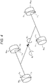
Fig. 4 is a diagram illustrating a balanced state between a moment according to a pitch damping force and a roll damping force, a pitch moment, and a roll moment. -
Fig. 5 is a diagram illustrating an exemplary configuration of a road input reduction control calculation unit. -
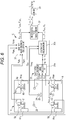
Fig. 6 is a diagram illustrating another variation of the suspension system. - Hereinafter, the present invention will be described on the basis of embodiments with reference to the drawings. As illustrated in
Fig. 1 , a suspension system S includes four actuators AFR, AFL, ARR, and ARL interposed between a body B of a vehicle V and four front and rear, right and left wheels WFR, WFL, WRR, and WRL of the vehicle V, and a controller C for controlling the actuators AFR, AFL, ARR, and ARL. - As illustrated in
Fig. 2 , the actuators AFR, AFL, ARR, and ARL each includes an extensible cylinder device AC, a pump 4, and a hydraulic circuit FC provided between the cylinder device AC and the pump 4 to supply a fluid discharged from the pump 4 to the cylinder device AC to extend and contract the cylinder device AC. - In this suspension system S, the cylinder device AC includes a
cylinder 1, apiston 2 movably inserted into thecylinder 1 to partition thecylinder 1 into an extension chamber R1 and an compression chamber R2, and a rod 3 movably inserted into thecylinder 1 to be connected to thepiston 2. The rod 3 passes through only the extension chamber R1, and the cylinder device AC is a so-called single rod cylinder device. Note that a reservoir R is provided independent of the cylinder device AC, inFig. 2 , but, without detailed illustration, an outer cylinder may be provided to be disposed on the outer peripheral side of thecylinder 1 in the cylinder device AC to form an annular gap as the reservoir R between thecylinder 1 and the outer cylinder. - The cylinder device AC is interposed between the body B and each of the wheels WFR, WFL, WRR, and WRL by connecting the
cylinder 1 to one of the body B of the vehicle V and each of the wheels WFR, WFL, WRR, and WRL and connecting the rod 3 to the other of the body B and each of the wheels WFR, WFL, WRR, and WRL. Note that between the body B and each of the wheels WFR, WFL, WRR, and WRL, a suspension spring Sp is interposed in parallel to the cylinder device AC. - Then, the fluid, such as hydraulic oil, is filled in the extension chamber R1 and the compression chamber R2, and the fluid is accumulated in the reservoir R. The fluid is also filled in the reservoir R and a gas spring, a spring, or both of the springs press the filled fluid. For the fluid filled in the extension chamber R1, the compression chamber R2, the reservoir R, and the reservoir R, a fluid, such as water or aqueous solution, may be employed in addition to the hydraulic oil. Furthermore, in the present invention, a chamber compressed during an extension process is defined as the extension chamber R1, and a chamber compressed during a contraction process is defined as the compression chamber R2.
- The pump 4 has a suction side from which the fluid is sucked and a discharge side from which the fluid is discharged for unidirectional discharge of the fluid, and the pump is driven by a
motor 13. Themotor 13 may employ various types of motors, such as a brushless motor, an induction motor, or a synchronous motor, regardless of direct current or alternate current. - The suction side of the pump 4 is connected to the reservoir R through the
pump passage 14, and the discharge side is connected to the hydraulic circuit FC. Accordingly, the pump 4 driven by themotor 13 sucks the fluid from the reservoir R and discharges the fluid to the hydraulic circuit FC. - Furthermore, the
motor 13 for driving the pump 4 is controlled by the controller C. The controller C can adjust the amount of current to be supplied to themotor 13, and can control the rotation rate of the pump 4, in addition to driving and stopping the pump 4. That is, the pump 4 is driven and controlled by the controller C. - The hydraulic circuit FC includes an electromagnetic valve controlled by the controller C, and the fluid discharged from the pump 4 can be supplied to the extension chamber R1 and the compression chamber R2 in the cylinder device AC. Furthermore, the hydraulic circuit FC discharges the rest of the fluid discharged from any of the extension chamber R1 and the compression chamber R2 and the rest of the fluid discharged from the pump 4 to the reservoir R. In addition, in accordance with a command from the controller C, the hydraulic circuit FC adjusts the extension chamber R1 and the compression chamber R2 in pressure to control the thrust of the cylinder device AC, causing the cylinder device AC to function as active suspension. As described above, the controller C can control the thrust in each of the actuators AFR, AFL, ARR, and ARL in accordance with a target control force obtained by the controller C itself.
- As illustrated in
Fig. 1 , the controller C includes threeacceleration sensors acceleration sensor 24, anacceleration sensor 25,acceleration sensors control calculation unit 30, a road input reductioncontrol calculation unit 31, a target controlforce calculation unit 32, and adriver 33. The threeacceleration sensors acceleration sensor 24 is installed in the body B to detect a lateral acceleration Glat of the body B, theacceleration sensor 25 is installed in the body B to detect a longitudinal acceleration Glong of the body B, theacceleration sensors driver 33 drives themotor 13, and the electromagnetic valve in the hydraulic circuit FC. - The
acceleration sensors acceleration sensors control calculation unit 30. Theacceleration sensor 24 and theacceleration sensor 25 input the detected lateral acceleration Glat and longitudinal acceleration Glong, to the bodycontrol calculation unit 30. Theacceleration sensors control calculation unit 31. - The body
control calculation unit 30 includes aspeed calculation unit 30a and a controlforce calculation unit 30b. Thespeed calculation unit 30a processes the accelerations G1, G2, and G3 to determine a bounce rate VB, a pitch rate Vp, and a roll rate VR of the body B, and the controlforce calculation unit 30b determines body control forces FFR, FFL, FRR, and FRL to be generated by the four actuators AFR, AFL, ARR, and ARL on the basis of the bounce rate VB, the pitch rate VP, the roll rate VR, the lateral acceleration Glat, and the longitudinal acceleration Glong determined by thespeed calculation unit 30a. - The
speed calculation unit 30a firstly integrates the accelerations G1, G2, and G3 to determine three vertical rates. When obtaining vertical rates at any three non-collinear points in the longitudinal direction or lateral direction of the body B, considering the body B as a rigid body, the rates of vertical, longitudinal, and lateral rotations of the body B can be obtained. Thus, on the basis of these rates, thespeed calculation unit 30a determines the bounce rate VB as a vertical rate at the position of the center of gravity of the body B, the pitch rate VP as an angular rate of rotation in the front-back direction at the position of the center of gravity, and an angular rate of rotation in the lateral direction at the center of gravity and the roll rate VR. - The control
force calculation unit 30b receives the input of the bounce rate VB, the pitch rate VP, and the roll rate VR determined by thespeed calculation unit 30a, and the lateral acceleration Glat and the longitudinal acceleration Glong detected by theacceleration sensor 24 and theacceleration sensor 25. Then, the controlforce calculation unit 30b determines the body control forces FFR, FFL, FRR, and FRL, on the basis of the bounce rate VB, the pitch rate VP, the roll rate VR, the lateral acceleration Glat, and the longitudinal acceleration Glong. - As illustrated in
Fig. 3 , a longitudinal distance from the center of gravity to the front wheels WFR and WFL is designated LF, a longitudinal distance from the center of gravity to the rear wheels WRR and WRL is designated LR, and tread between the right wheel WFR (WRR) and the left wheel WFL (WRL) is designated W. The controlforce calculation unit 30b multiplies the bounce rate VB by a gain to determine a control force for damping the vertical vibration of the body B. - Furthermore, the control
force calculation unit 30b multiplies the pitch rate Vp by the gain to determine a damping moment in a pitch direction, and divides the damping moment by wheelbase (LF+LR) to determine a control force for damping the vibration of the body B due to pitching. - Furthermore, the control
force calculation unit 30b multiplies the roll rate VR by the gain to determine a damping moment in a roll direction, and divides the damping moment by tread W to determine a control force for damping the vibration of the body B due to rolling. - Furthermore, the control
force calculation unit 30b multiplies the input longitudinal acceleration Glong by the gain to determine a control force required to prevent pitching of the body B due to inertial force acting in the longitudinal direction. - Then, the control
force calculation unit 30b multiplies the input lateral acceleration Glat by the gain to determine a control force required to prevent rolling of the body B due to centrifugal force. - As described above, the control
force calculation unit 30b determines the control forces, on the basis of the bounce rate VB, the pitch rate VP, the roll rate VR, the longitudinal acceleration Glong, and the lateral acceleration Glat. Note that the control forces are determined, designating a sign of a downward force positive, and a sign of an upward force negative. Then, the controlforce calculation unit 30b determines the body control forces FFR, FFL, FRR, and FRL which are to be generated from the respective actuators AFR, AFL, ARR, and ARL, on the basis of these five control forces. - To damp the bounce of the body B, the actuators AFR, AFL, ARR, and ARL need to generate control forces directed in the same direction and having the same magnitude. To damp pitching of the body B, the front actuators AFR and AFL and the rear actuators ARR and ARL need to generate control forces having the same magnitude and directed in the opposite directions. To damp rolling of the body B, the right actuators AFR and ARR and the left actuators AFL and ARL need to generate control forces having the same magnitude and directed in the opposite directions.
- Thus, the control
force calculation unit 30b adds a control force determined on the basis of the bounce rate VB, a control force determined on the basis of the pitch rate VP and the lateral acceleration Glat, and a control force determined on the basis of the roll rate VR and the lateral acceleration Glong to damp the bouncing, pitching, and rolling of the body B, and determines the body control forces FFR, FFL, FRR, and FRL which are to be generated from the respective actuators AFR, AFL, ARR, and ARL. The determined body control forces FFR, FFL, FRR, and FRL are input to the target controlforce calculation unit 32. - The road input reduction
control calculation unit 31 determines road input reduction control forces FCFR, FCFL, FCRR, and FCRL on the basis of the vertical accelerations GUFR, GUFL, GURR, and GURL. When the wheels WFR, WFL, WRR, and WRL vibrate, the suspension springs Sp expand and contract, generating a vibrating force causing the body B to roll and pitch. The road input reduction control forces FCFR, FCFL, FCRR, and FCRL are each a force for cancelling the vibrating force caused by the expansion and contraction of the suspension spring Sp to vibrate the body B. - When the pitch angle is α, the roll angle is β, a spring constant of a suspension spring Sp of a front wheel is KF, a spring constant of a suspension spring of a rear wheel is KR, and displacements in a vertical direction (vertical displacements) of the wheels WFR, WFL, WRR, and WRL are XUFR, XUFL, XURR, and XURL, pitch moment MSP and roll moment MSR caused by forces generated by the suspension springs Sp are expressed by the following (formula 1) and (formula 2).
[Mathematical Formula 1]
[Mathematical Formula 2]
- In each of (formula 1) and (formula 2), the first term on the right side is a restoring force against the rolling or pitching of the body B, and the second term and the third term are considered as moment inputs vibrating the body B upon displacement of the wheels WFR, WFL, WRR, and WRL.
- When forces obtained by multiplying the vertical displacements XUFR, XUFL, XURR, and XURL of the wheels WFR, WFL, WRR, and WRL by the spring constants KF and KR are FUFR, FUFL, FURR, and FURL, a pitch moment MP and a roll moment MR generated by the forces are expressed by the following (formula 3) and (formula 4).
[Mathematical Formula 3]
[Mathematical Formula 4]
- While, as illustrated in
Fig. 4 , consider moments MPC and MRC cancelling the moments MP and MR by applying pitch damping forces FP having the same magnitude and acting in the opposite directions by the front actuators AFR and AFL and the rear actuators ARR and ARL of the vehicle V, and applying roll damping forces FR having the same magnitude and acting in the opposite directions by the right actuators AFR and ARR and the left actuators AFL and ARL of the vehicle V. Then, the moments MPC and MRC are expressed by the following (formula 5) and (formula 6).
[Mathematical Formula 5]
[Mathematical Formula 6]
- To cancel the moments MP and MR by the moments MPC and MRC, conditions of MP = MPC and MR = MRC are desirably satisfied. When (formula 5) and (formula 6) are solved for a pitch damping force FP and a roll damping force FR while satisfying these conditions, the following (formula 7) and (formula 8) can be derived.
[Mathematical Formula 7]
[Mathematical Formula 8]
- To determine the road input reduction control forces FCFR, FCFL, FCRR, and FCRL to be generated by the actuators AFR, AFL, ARR, and ARL on the basis of the pitch damping force FP and the roll damping force FR determined by (formula 7) and (formula 8) to damp pitching and rolling, designating the sign of a downward force positive, the following (formula 9), (formula 10), (formula 11), and (formula 12) are desirably calculated.
[Mathematical Formula 9]
[Mathematical Formula 10]
[Mathematical Formula 11]
[Mathematical Formula 12]
- The spring constants KF and KR of the suspension springs Sp, the distances LF and LR from the center of gravity, and the tread W are already given. Furthermore, the vertical displacements XUFR, XUFL, XURR, and XURL of the wheels WFR, WFL, WRR, and WRL can be determined only by integrating twice the vertical accelerations GUFR, GUFL, GURR, and GURL input from the
acceleration sensors - Thus, the road input reduction
control calculation unit 31 can determine the road input reduction control forces FCFR, FCFL, FCRR, and FCRL, on the basis of the spring constants KF and KR of the suspension springs Sp, the distances LF and LR, the tread W, and the vertical accelerations GUFR, GUFL, GURR, and GURL. - As illustrated in
Fig. 5 , the road input reductioncontrol calculation unit 31 includesintegrators multipliers multipliers adder 48, anadder 49, anadder 50, amultiplier 51, amultiplier 52, amultiplier 53, anadder 54, anadder 55, anadder 56, anadder 57, and anadder 58. Theintegrators acceleration sensors multipliers integrators multipliers integrators adder 48 adds the forces FUFR and FUFL. Theadder 49 adds the forces FURR and FURL. Theadder 50 adds a value obtained by subtracting the force FURL from the force FURR to a value obtained by subtracting the force FUFL from the force FUFR. Themultiplier 51 multiplies a value output from theadder 48 by LF/{(2(LF + LR)}. Themultiplier 52 multiplies a value output from theadder 49 by LR/{(2(LF + LR)}. Themultiplier 53 multiplies a value output from theadder 50 by 1/4 to determine the roll damping force FR. Theadder 54 subtracts a value output from themultiplier 52 from a value output from themultiplier 51 to determine the pitch damping force FP. Theadder 55 adds the roll damping force FR to the pitch damping force FP to obtain the road input reduction control force FCFR. Theadder 56 subtracts the roll damping force FR from the pitch damping force FP to determine the road input reduction control force FCFL. Theadder 57 changes the sign of the pitch damping force FP and adds the roll damping force FR to the pitch damping force FP to determine the road input reduction control force FCRR. Theadder 58 changes the signs of the pitch damping force FP and the roll damping force FR and adds the pitch damping force FP and the roll damping force FR to each other to determine the road input reduction control force FCFL. - After the vertical accelerations GUFR, GUFL, GURR, and GURL input to respective units of the road input reduction
control calculation unit 31 are processed, calculation from (formula 7) to (formula 12) is performed in the road input reductioncontrol calculation unit 31, and the road input reduction control forces FCFR, FCFL, FCRR, and FCRL are determined. - The road input reduction control forces FCFR, FCFL, FCRR, and FCRL obtained as described above are input to the target control
force calculation unit 32. As described above, in addition to the road input reduction control forces FCFR, FCFL, FCRR, and FCRL, the body control forces FFR, FFL, FRR, and FRL are input to the target controlforce calculation unit 32. - The target control
force calculation unit 32 adds the road input reduction control forces FCFR, FCFL, FCRR, and FCRL to the body control forces FFR, FFL, FRR, and FRL, respectively, to determine target control forces FTFR, FTFL, FTRR, and FTRL for the actuators AFR, AFL, ARR, and ARL. After determining the target control forces FTFR, FTFL, FTRR, and FTRL, the target controlforce calculation unit 32 outputs the target control forces FTFR, FTFL, FTRR, and FTRL to thedrivers 33. - The
drivers 33 are provided for the respective actuators AFR, AFL, ARR, and ARL, and each includes a drive circuit for driving the electromagnetic valve in the hydraulic circuit FC by PWM, and a drive circuit for driving themotor 13 for driving the pump 4 by PWM. When receiving input of commands for the target control forces FTFR, FTFL, FTRR, and FTRL from the target controlforce calculation unit 32, eachdriver 33 supplies current to the electromagnetic valve and themotor 13 in accordance with each command. Note that each drive circuit in thedriver 33 may be a drive circuit other than the drive circuit performing the PWM drive. - When the target control forces FTFR, FTFL, FTRR, and FTRL are a thrust force applied to each cylinder device AC in an extension direction, the controller C controls the electromagnetic valve of the hydraulic circuit FC, to supply the fluid discharged from the pump 4 to the compression chamber R2, and controls the pressure in the compression chamber R2 in accordance with the magnitude of each of the target control forces FTFR, FTFL, FTRR, and FTRL. In contrast, when the target control forces FTFR, FTFL, FTRR, and FTRL are a thrust force applied to each cylinder device AC in a contraction direction, the controller C controls the electromagnetic valve of the hydraulic circuit FC to supply the fluid discharged from the pump 4 to the extension chamber R1, and controls the pressure in the extension chamber R1 in accordance with the magnitude of each of the target control forces FTFR, FTFL, FTRR, and FTRL.
- Note that, in the present example, the actuators AFR, AFL, ARR, and ARL are each a hydraulic actuator including the cylinder device AC and the hydraulic circuit FC, but the actuators AFR, AFL, ARR, and ARL may be each an electric actuator using a motor. Furthermore, the actuators AFR, AFL, ARR, and ARL may be each a pneumatic actuator pneumatically driven.
- As described above, the suspension system S is configured to determine the pitch damping force FP and the roll damping force FR for cancelling the roll and pitch moments MP and MR of the body B, respectively, determine the target control forces FTFR, FTFL, FTRR, and FTRL in consideration of the pitch damping force FP and the roll damping force FR, and control the actuators AFR, AFL, ARR, and ARL. When the pitch damping force FP and the roll damping force FR are output to the actuators AFR, AFL, ARR, and ARL, the actuators AFR, AFL, ARR, and ARL each generate a control force for cancelling a force acting on the body B not later but preliminarily. Thus, the suspension system S according to the present invention can generate a control force for preliminarily damping the vibration of the body B to efficiently damp the vibration of the body B, as compared with a conventional suspension system detecting the vibration of the body B and then generating only a control force for damping the vibration. As described above, in the suspension system S according to the present invention, the vibration of the body B caused by the vibration of the wheels WFR, WFL, WRR, and WRL can be cancelled, and the body B can have an improved vibration damping effect.
- Furthermore, the suspension system S according to the present example is configured to add the road input reduction control forces FCFR, FCFL, FCRR, and FCRL determined on the basis of the pitch damping force Fp and the roll damping force FR to the body control forces FFR, FFL, FRR, and FRL for damping detected vibration of the body B, and determine the target control forces FTFR, FTFL, FTRR, and FTRL. Accordingly, according to the suspension system S of the present example, the control force for preliminarily damping the vibration of the body B can be generated, in addition to the control force for damping the detected vibration of the body B. Thus, in the suspension system S according to the present example, the body B has a considerably improved vibration damping effect, as compared with the conventional suspension system.
- Furthermore, the controller C is configured to determine the roll moment MPC and the pitch moment MRC which act on the body B, on the basis of the vertical displacements XUFR, XUFL, XURR, and XURL of the four wheels WFR, WFL, WRR, and WRL, and determine the pitch damping force FP and the roll damping force FR on the basis of the roll moment MPC and the pitch moment MRC. When the roll moment MPC and the pitch moment MRC which act on the body B are determined on the basis of the vertical displacements XUFR, XUFL, XURR, and XURL, the roll moment MPC and the pitch moment MRC which act on the body B can be readily and accurately determined on the basis of the vibrations of the four wheels WFR, WFL, WRR, and WRL. Then, when the pitch damping force FP and the roll damping force FR are determined on the basis of thus obtained roll moment MPC and pitch moment MRC, a control force can be appropriately generated at appropriate time on the basis of the pitch damping force FP and the roll damping force FR, with a reduced calculation load.
- Furthermore, the controller C controls the pitch damping forces FP caused to be generated by the actuators AFR and AFL disposed on the front side and the pitch damping forces FP caused to be generated by the actuators ARR and ARL disposed on the rear side to have the same magnitude and to be directed in the opposite directions, and controls the roll damping forces FR caused to be generated by the actuators AFR and ARR disposed on the right side and the roll damping forces FR caused to be generated by the actuators AFL and ARL on the left side to have the same magnitude and to be directed in the opposite directions. Since such a configuration as described above damps the pitching and rolling of the body B without the influence of the vertical vibration on the body B, pitching vibration and rolling vibration of the body B can be reduced considerably.
- Note that the vertical displacements XUFR, XUFL, XURR, and XURL of the wheels WFR, WFL, WRR, and WRL can be also determined on the basis of the vertical accelerations G1, G2, and G3 detected by the
acceleration sensors Fig. 6 , the relative displacements between the body B and the wheels WFR, WFL, WRR, and WRL can be obtained withstroke sensors stroke sensors stroke sensors acceleration sensors - The
stroke sensors - As described above, on the basis of the vertical accelerations G1, G2, and G3 detected by the
acceleration sensors
[Mathematical Formula 13]
[Mathematical Formula 14]
[Mathematical Formula 15]
[Mathematical Formula 16]
- When relative displacements detected by the
stroke sensors
[Mathematical Formula 17]
[Mathematical Formula 18]
[Mathematical Formula 19]
[Mathematical Formula 20]
- As described above, the vertical displacements XUFR, XUFL, XURR, and XURL may be determined on the basis of the vertical accelerations G1, G2, and G3 detected by the
acceleration sensors stroke sensors - The preferred embodiments of the present invention has been described in detail above, but modifications, alterations, and changes may be made without departing from the spirit and scope of the present invention.
- This application claims the benefit of Japanese Priority Patent Application
JP 2015-226990 filed on November 19, 2015
Claims (5)
- A suspension system comprising:four actuators interposed between a body of a vehicle and four front and rear, right and left wheels of the vehicle; anda controller for controlling the actuators, whereinthe controller controls the actuators bydetermining a pitch damping force and a roll damping force to cancel roll and pitch moments of the body, respectively, on the basis of vertical displacements of the four front and back, right and left wheels in the vehicle, anddetermining a target control force for each of the actuators on the basis of the pitch damping force and the roll damping force.
- The suspension system according to claim 1, wherein
the controller
determines a pitch moment and a roll moment which act on the body, on the basis of the vertical displacements of the four wheels, and
determines the pitch damping force and the roll damping force on the basis of the pitch moment and the roll moment. - The suspension system according to claim 1, wherein
the controller controls
the pitch damping forces caused to be generated by the actuators disposed on the front side in the vehicle and the pitch damping forces caused to be generated by the actuators disposed on the rear side in the vehicle to have the same magnitude and to be directed in the opposite directions, and
the roll damping forces caused to be generated by the actuators disposed on the right side in the vehicle and the roll damping forces caused to be generated by the actuators disposed on the left side in the vehicle to have the same magnitude and to be directed in the opposite directions. - The suspension system according to claim 1, wherein
the controller
determines vertical displacements of the wheels, on the basis of vertical accelerations of the wheels detected by acceleration sensors provided at the wheels, or
determines vertical displacements of the wheels, on the basis of vertical accelerations of the body detected by acceleration sensors provided in the body, and relative displacements between the body and the wheels detected by stroke sensors provided between the wheels and the body. - The suspension system according to claim 1, wherein
the controller
detects vibration of the body to determine body control forces on the basis of the vibration,
determines road input reduction control forces on the basis of the roll damping force and the pitch damping force, and
determines the target control forces by adding the body control forces to the road input reduction control forces.
Applications Claiming Priority (2)
| Application Number | Priority Date | Filing Date | Title |
|---|---|---|---|
| JP2015226990A JP6879661B2 (en) | 2015-11-19 | 2015-11-19 | Suspension device |
| PCT/JP2016/077663 WO2017086015A1 (en) | 2015-11-19 | 2016-09-20 | Suspension device |
Publications (1)
| Publication Number | Publication Date |
|---|---|
| EP3378682A1 true EP3378682A1 (en) | 2018-09-26 |
Family
ID=58718664
Family Applications (1)
| Application Number | Title | Priority Date | Filing Date |
|---|---|---|---|
| EP16866018.1A Withdrawn EP3378682A1 (en) | 2015-11-19 | 2016-09-20 | Suspension device |
Country Status (6)
| Country | Link |
|---|---|
| US (1) | US20180326809A1 (en) |
| EP (1) | EP3378682A1 (en) |
| JP (1) | JP6879661B2 (en) |
| KR (1) | KR20180063241A (en) |
| CN (1) | CN108290470A (en) |
| WO (1) | WO2017086015A1 (en) |
Families Citing this family (5)
| Publication number | Priority date | Publication date | Assignee | Title |
|---|---|---|---|---|
| KR102589031B1 (en) * | 2018-12-06 | 2023-10-17 | 현대자동차주식회사 | Control unit of active suspension and control method of active suspension |
| JP7180638B2 (en) * | 2020-06-08 | 2022-11-30 | トヨタ自動車株式会社 | VEHICLE RUNNING STATE CONTROL DEVICE AND METHOD |
| EP4169822A4 (en) * | 2020-06-23 | 2024-03-27 | Hitachi Astemo, Ltd. | Calibration device, suspension system, saddle-type vehicle, and calibration method |
| JP7314904B2 (en) * | 2020-10-30 | 2023-07-26 | トヨタ自動車株式会社 | Vibration control device |
| CN117799374B (en) * | 2022-09-26 | 2024-10-29 | 比亚迪股份有限公司 | Semi-active suspension control method and device, storage medium and vehicle |
Family Cites Families (9)
| Publication number | Priority date | Publication date | Assignee | Title |
|---|---|---|---|---|
| JPH0832503B2 (en) | 1989-08-09 | 1996-03-29 | 日産自動車株式会社 | Active suspension |
| JPH0832502B2 (en) | 1989-08-09 | 1996-03-29 | 日産自動車株式会社 | Active suspension |
| JP3156502B2 (en) * | 1994-05-24 | 2001-04-16 | 日産自動車株式会社 | Suspension preview control device |
| JP3185566B2 (en) * | 1994-10-28 | 2001-07-11 | 日産自動車株式会社 | Suspension control device |
| JP2005081912A (en) * | 2003-09-05 | 2005-03-31 | Toyota Motor Corp | Vehicle suspension system |
| JP4960715B2 (en) * | 2007-02-01 | 2012-06-27 | 本田技研工業株式会社 | Vehicle equipped with damper with variable damping force |
| EP2052891B1 (en) * | 2007-10-26 | 2013-02-27 | Honda Motor Co., Ltd. | Control device for a variable damper |
| US8838336B2 (en) * | 2010-07-29 | 2014-09-16 | Hitachi Automotive Systems, Ltd. | Vehicle body attitude control apparatus |
| EP2868499B1 (en) * | 2012-06-29 | 2018-11-21 | Honda Motor Co., Ltd. | Suspension control device |
-
2015
- 2015-11-19 JP JP2015226990A patent/JP6879661B2/en active Active
-
2016
- 2016-09-20 US US15/773,631 patent/US20180326809A1/en not_active Abandoned
- 2016-09-20 CN CN201680066312.XA patent/CN108290470A/en active Pending
- 2016-09-20 WO PCT/JP2016/077663 patent/WO2017086015A1/en not_active Ceased
- 2016-09-20 EP EP16866018.1A patent/EP3378682A1/en not_active Withdrawn
- 2016-09-20 KR KR1020187012491A patent/KR20180063241A/en not_active Withdrawn
Also Published As
| Publication number | Publication date |
|---|---|
| KR20180063241A (en) | 2018-06-11 |
| JP2017094807A (en) | 2017-06-01 |
| CN108290470A (en) | 2018-07-17 |
| JP6879661B2 (en) | 2021-06-02 |
| WO2017086015A1 (en) | 2017-05-26 |
| US20180326809A1 (en) | 2018-11-15 |
Similar Documents
| Publication | Publication Date | Title |
|---|---|---|
| EP3378682A1 (en) | Suspension device | |
| EP3216634A1 (en) | Suspension device and suspension control device | |
| KR0169315B1 (en) | Semi-automatic suspension control method and device | |
| US20050279244A1 (en) | Active suspension controller | |
| US10124644B2 (en) | Damper control device | |
| JP5652053B2 (en) | Vehicle vibration estimation device and vehicle system vibration control device using the same | |
| US11498382B2 (en) | Controlling damper friction effects in a suspension | |
| WO2012026441A1 (en) | Device for estimating vehicle body vibration and controller for suppressing vehicle body vibration using same | |
| JP2009241813A (en) | Vehicle vibrating state detecting method, and suspension controlling method and device using the same | |
| EP3109142A1 (en) | Damper control device | |
| JP7112533B2 (en) | suspension device | |
| US20050087098A1 (en) | Position adjustment of a vehicle car body | |
| US12434524B2 (en) | Slip state detection apparatus and suspension control apparatus | |
| JP5834368B2 (en) | Damper control device | |
| US10226979B2 (en) | Damping force control device for vehicle | |
| JP5427072B2 (en) | Vibration control device for railway vehicles | |
| JP6408828B2 (en) | Suspension device | |
| JP5702200B2 (en) | Shock absorber controller | |
| CN110214277B (en) | Constant acceleration detection device and shock absorber for railway vehicles | |
| WO2018056130A1 (en) | Suspension device | |
| JP2997975B2 (en) | Vehicle suspension control device | |
| RU146626U1 (en) | HYDRO-PNEUMATIC SUSPENSION OF A VEHICLE WHEEL | |
| JP4664759B2 (en) | Stroke sensor abnormality determination device | |
| WO2018159511A1 (en) | Railroad car vibration damping device | |
| KR102430488B1 (en) | Active Suspension System for Vehicle |
Legal Events
| Date | Code | Title | Description |
|---|---|---|---|
| PUAI | Public reference made under article 153(3) epc to a published international application that has entered the european phase |
Free format text: ORIGINAL CODE: 0009012 |
|
| 17P | Request for examination filed |
Effective date: 20180615 |
|
| AK | Designated contracting states |
Kind code of ref document: A1 Designated state(s): AL AT BE BG CH CY CZ DE DK EE ES FI FR GB GR HR HU IE IS IT LI LT LU LV MC MK MT NL NO PL PT RO RS SE SI SK SM TR |
|
| AX | Request for extension of the european patent |
Extension state: BA ME |
|
| STAA | Information on the status of an ep patent application or granted ep patent |
Free format text: STATUS: THE APPLICATION HAS BEEN WITHDRAWN |
|
| DAV | Request for validation of the european patent (deleted) | ||
| DAX | Request for extension of the european patent (deleted) | ||
| 18W | Application withdrawn |
Effective date: 20190221 |