EP3378657A1 - Printing apparatus - Google Patents
Printing apparatus Download PDFInfo
- Publication number
- EP3378657A1 EP3378657A1 EP18162507.0A EP18162507A EP3378657A1 EP 3378657 A1 EP3378657 A1 EP 3378657A1 EP 18162507 A EP18162507 A EP 18162507A EP 3378657 A1 EP3378657 A1 EP 3378657A1
- Authority
- EP
- European Patent Office
- Prior art keywords
- section
- printing
- attachment section
- circuit board
- printing apparatus
- Prior art date
- Legal status (The legal status is an assumption and is not a legal conclusion. Google has not performed a legal analysis and makes no representation as to the accuracy of the status listed.)
- Granted
Links
Images

Classifications
-
- B—PERFORMING OPERATIONS; TRANSPORTING
- B41—PRINTING; LINING MACHINES; TYPEWRITERS; STAMPS
- B41J—TYPEWRITERS; SELECTIVE PRINTING MECHANISMS, i.e. MECHANISMS PRINTING OTHERWISE THAN FROM A FORME; CORRECTION OF TYPOGRAPHICAL ERRORS
- B41J29/00—Details of, or accessories for, typewriters or selective printing mechanisms not otherwise provided for
- B41J29/02—Framework
-
- B—PERFORMING OPERATIONS; TRANSPORTING
- B41—PRINTING; LINING MACHINES; TYPEWRITERS; STAMPS
- B41J—TYPEWRITERS; SELECTIVE PRINTING MECHANISMS, i.e. MECHANISMS PRINTING OTHERWISE THAN FROM A FORME; CORRECTION OF TYPOGRAPHICAL ERRORS
- B41J2/00—Typewriters or selective printing mechanisms characterised by the printing or marking process for which they are designed
- B41J2/005—Typewriters or selective printing mechanisms characterised by the printing or marking process for which they are designed characterised by bringing liquid or particles selectively into contact with a printing material
- B41J2/01—Ink jet
-
- B—PERFORMING OPERATIONS; TRANSPORTING
- B41—PRINTING; LINING MACHINES; TYPEWRITERS; STAMPS
- B41J—TYPEWRITERS; SELECTIVE PRINTING MECHANISMS, i.e. MECHANISMS PRINTING OTHERWISE THAN FROM A FORME; CORRECTION OF TYPOGRAPHICAL ERRORS
- B41J2/00—Typewriters or selective printing mechanisms characterised by the printing or marking process for which they are designed
- B41J2/005—Typewriters or selective printing mechanisms characterised by the printing or marking process for which they are designed characterised by bringing liquid or particles selectively into contact with a printing material
- B41J2/01—Ink jet
- B41J2/015—Ink jet characterised by the jet generation process
- B41J2/04—Ink jet characterised by the jet generation process generating single droplets or particles on demand
- B41J2/045—Ink jet characterised by the jet generation process generating single droplets or particles on demand by pressure, e.g. electromechanical transducers
- B41J2/04501—Control methods or devices therefor, e.g. driver circuits, control circuits
-
- B—PERFORMING OPERATIONS; TRANSPORTING
- B41—PRINTING; LINING MACHINES; TYPEWRITERS; STAMPS
- B41J—TYPEWRITERS; SELECTIVE PRINTING MECHANISMS, i.e. MECHANISMS PRINTING OTHERWISE THAN FROM A FORME; CORRECTION OF TYPOGRAPHICAL ERRORS
- B41J2/00—Typewriters or selective printing mechanisms characterised by the printing or marking process for which they are designed
- B41J2/005—Typewriters or selective printing mechanisms characterised by the printing or marking process for which they are designed characterised by bringing liquid or particles selectively into contact with a printing material
- B41J2/01—Ink jet
- B41J2/17—Ink jet characterised by ink handling
- B41J2/175—Ink supply systems ; Circuit parts therefor
- B41J2/17503—Ink cartridges
- B41J2/1752—Mounting within the printer
-
- B—PERFORMING OPERATIONS; TRANSPORTING
- B41—PRINTING; LINING MACHINES; TYPEWRITERS; STAMPS
- B41J—TYPEWRITERS; SELECTIVE PRINTING MECHANISMS, i.e. MECHANISMS PRINTING OTHERWISE THAN FROM A FORME; CORRECTION OF TYPOGRAPHICAL ERRORS
- B41J29/00—Details of, or accessories for, typewriters or selective printing mechanisms not otherwise provided for
-
- B—PERFORMING OPERATIONS; TRANSPORTING
- B41—PRINTING; LINING MACHINES; TYPEWRITERS; STAMPS
- B41J—TYPEWRITERS; SELECTIVE PRINTING MECHANISMS, i.e. MECHANISMS PRINTING OTHERWISE THAN FROM A FORME; CORRECTION OF TYPOGRAPHICAL ERRORS
- B41J29/00—Details of, or accessories for, typewriters or selective printing mechanisms not otherwise provided for
- B41J29/38—Drives, motors, controls or automatic cut-off devices for the entire printing mechanism
- B41J29/393—Devices for controlling or analysing the entire machine ; Controlling or analysing mechanical parameters involving printing of test patterns
-
- B—PERFORMING OPERATIONS; TRANSPORTING
- B41—PRINTING; LINING MACHINES; TYPEWRITERS; STAMPS
- B41J—TYPEWRITERS; SELECTIVE PRINTING MECHANISMS, i.e. MECHANISMS PRINTING OTHERWISE THAN FROM A FORME; CORRECTION OF TYPOGRAPHICAL ERRORS
- B41J2/00—Typewriters or selective printing mechanisms characterised by the printing or marking process for which they are designed
- B41J2/005—Typewriters or selective printing mechanisms characterised by the printing or marking process for which they are designed characterised by bringing liquid or particles selectively into contact with a printing material
- B41J2/01—Ink jet
- B41J2/17—Ink jet characterised by ink handling
- B41J2/175—Ink supply systems ; Circuit parts therefor
- B41J2/17503—Ink cartridges
- B41J2/17526—Electrical contacts to the cartridge
Definitions
- the present invention relates to printing apparatuses such as printers.
- Examples of the printing apparatuses include ink jet recording apparatuses having a cartridge attachment section for attaching a liquid pack in the upper part of a housing.
- JP-A-2016-22626 is an example of related art.
- the cartridge attachment section located at a raised position may cause difficulty in visual observation of the position for attaching or detaching the liquid pack. Not only in the case of attaching the liquid pack in the cartridge attachment section, but also in the case where an attachment section for attaching a component is located at a position that cannot be easily observed, operations may become troublesome.
- An advantage of some aspects of the invention is that a printing apparatus that enables ease of attachment and detachment of a component is provided.
- the printing apparatus for solving the above problem includes a printing section configured to perform printing onto a medium while reciprocating in a movement area, and an attachment section to which a component can be attached, wherein the attachment section is movable between a first position above the movement area and a second position which is at least partially within the movement area.
- the printing apparatus is, for example, an ink jet printer that performs printing by ejecting ink which is an example of the liquid onto a medium such as a paper sheet.
- a printing apparatus 11 includes a housing 12, legs 13 that support the housing 12, a printing section 20, a maintenance mechanism 30, and an attachment section 24 on which a liquid container 23 can be attached.
- the printing section 20, the maintenance mechanism 30, and the attachment section 24 are housed in the housing 12.
- the printing section 20 includes an ejecting head 21 to which nozzles 22 (see Fig. 3 ) are open so that liquid is ejected therethrough.
- the liquid container 23 is a tank that can store the liquid to be supplied to the printing section 20.
- the liquid container 23 may be a cartridge, which is a replaceable container.
- the printing section 20 is configured to perform printing onto a medium 99 while reciprocating in a movement area 14 which extends in a longitudinal direction of the housing 12. After printing is performed, the medium 99 is transported in a direction Y to the outside of the housing 12, and is hung in a gravitational direction Z.
- One and the other ends of the movement area 14 in the longitudinal direction are referred to as a first end 14f and a second end 14s, respectively.
- a direction from the first end 14f to the second end 14s is indicated as a direction X.
- the direction X, the direction Y, and the gravitational direction Z form a three-axis system.
- the printing apparatus 11 includes a guide shaft 15 that guides movement of the printing section 20, a medium support section 16 that can support the medium 99, a circuit board 100 which is an example of a component, and an attachment section 40 to which the circuit board 100 can be attached, which are housed in the housing 12.
- the circuit board 100 is a control unit that controls constituent elements of the printing apparatus 11 such as the printing section 20.
- the medium support section 16 is disposed between the first end 14f and the second end 14s in the longitudinal direction of the movement area 14.
- the medium support section 16 preferably has an end portion extending outside the housing 12 so as to support the medium 99 which is outputted outside the housing 12.
- the printing section 20 When in printing, the printing section 20 reciprocates between the first end 14f and the second end 14s of the movement area 14 while traversing the medium support section 16.
- the printing section 20 stands-by at a stand-by position which is closer to the second end 14s than to the medium support section 16.
- the attachment section 40 is preferably disposed at a position closer to the first end 14f than to the medium support section 16.
- the printing section 20 shown in Fig. 1 is located at the stand-by position.
- a cap 17 is preferably disposed at the stand-by position so as to cover the nozzles 22 (see Fig. 3 ).
- the maintenance mechanism 30 is disposed, for example, at a position closer to the first end 14f than to the medium support section 16.
- the maintenance mechanism 30 includes at least one of a wiping member 31, a suction mechanism 32, and a waste liquid receiver 33.
- the wiping member 31 wipes foreign substances such as liquid adhered to the ejecting head 21 while moving relative to the ejecting head 21.
- the suction mechanism 32 suctions the ejecting head 21 through the nozzles 22 to thereby purge foreign substances such as air bubbles residing in the printing section 20.
- the waste liquid receiver 33 receives the ejected waste liquid when the printing section 20 ejects liquid as waste liquid.
- the waste liquid receiver 33 may also be disposed at a position between the medium support section 16 and the second end 14s.
- one or more cables 18 are detachably attached to the circuit board 100.
- the cable 18 is an example of a component detachably attached to the circuit board 100 which is mounted on a fixation frame 41.
- the cable 18 may be a line for transmitting electric power to the circuit board 100 or may be a line for transmitting a signal to the printing section 20.
- the cable 18 may be a flexible flat cable or a wire harness, which is an assembly of a plurality of lines.
- a wall of the housing 12 which faces the attachment section 40 is preferably a removable cover 12a.
- the cover 12a can be disposed on the rear side of the housing 12 taking the surface of the housing 12 from which the medium 99 is outputted as the front side.
- the white arrow indicates the gaze of a user looking at the attachment section 40 in the housing 12 with the cover 12a being removed.
- the housing 12 is shown with the cover 12a removed. A portion of the housing 12 from which the cover 12a is removed is an opening 12b.
- the attachment section 40 is movable between a first position (the position indicated by the double-dotted and dashed line) above the movement area 14 and a second position (the position indicated by the solid line) which is at least partially within the movement area 14.
- the attachment section 40 is preferably fixed by a fastener such as a screw when located at the first position. In this case, the attachment section 40 moves to the second position by its own weight when released from the fixed state.
- the attachment section 40 preferably includes the fixation frame 41 on which the circuit board 100 can be mounted.
- the fixation frame 41 preferably has an aperture 41a that allows the cable 18 to pass therethrough.
- the cable 18 is preferably flexed so as to follow movement of the fixation frame 41.
- the attachment section 40 may also include a table 42 for carrying the circuit board 100. A gap is formed between the table 42 and the fixation frame 41 to promote heat dissipation of the circuit board 100. Further, a fastener such as a screw can protrude into the gap.
- the attachment section 40 is preferably configured to be tiltable between the first position and the second position.
- the bottom of the fixation frame 41 is substantially horizontal at the first position, and the bottom of the fixation frame 41 is tilted relative to the horizontal at the second position.
- the fixation frame 41 is preferably tilted with the distal end moving downward from the first position to the second position.
- the fixation frame 41 can be formed in a plate or box shape.
- the fixation frame 41 is disposed to face the inner surface (for example, a ceiling surface 12c) of the housing 12 when located at the first position so that the circuit board 100 is protected by the housing 12.
- a portion of the fixation frame 41 on which the circuit board 100 is mounted is oriented to the outside of the housing 12 to more of an extent than in the first position.
- the attachment section 40 is disposed at the first position above the movement area 14 during an operation such as printing in which the printing section 20 moves. As a result, the printing section 20 when moving does not come into contact with the attachment section 40.
- the user stops the printing section 20 at the stand-by position and removes the cover 12a from the housing 12. Then, the user moves the attachment section 40 from the first position to the second position. Since the printing section 20 is located at the stand-by position, it does not come into contact with the attachment section 40 when the attachment section 40 moves.
- the distal end of the fixation frame 41 which is the end closest to the user, comes at a position lower than the proximal end. Accordingly, the circuit board 100 held by the fixation frame 41 comes to a position that can be easily observed. As a result, a maintenance operation such as inspection of the circuit board 100 and replacement of the circuit board 100 can be smoothly performed.
- the maintenance operation also includes inspection, re-insertion, and replacement of the cable 18.
- a printing apparatus including a printing section configured to perform printing onto a medium while reciprocating in a movement area, and an attachment section to which a component can be attached, wherein the attachment section is movable between a first position above the movement area and a second position which is at least partially within the movement area.
- the printing apparatus according to the idea 1, wherein the attachment section is configured to be tiltable between the first position and the second position.
- the printing apparatus including a medium support section that supports the medium, wherein the printing section reciprocates between a first end and a second end of the movement area while traversing the medium support section when in printing, and stands-by at a stand-by position which is closer to the second end than to the medium support section when not in printing, and the attachment section is disposed at a position closer to the first end than to the medium support section.
- the printing section stands-by at the stand-by position which is spaced from the attachment section when not in printing.
- the attachment section does not come into contact with the printing section when moving to the second position.
- the printing apparatus according to any one of the ideas 1 to 3, wherein the component is a circuit board, and the attachment section includes a fixation frame which allows the circuit board to be mounted thereon.
- the attachment section includes a circuit board and a fixation frame which allows the circuit board to be mounted thereon, and the component is a cable that is detachably attached to the circuit board.
Landscapes
- Accessory Devices And Overall Control Thereof (AREA)
- Ink Jet (AREA)
Abstract
Description
- The present invention relates to printing apparatuses such as printers.
- Examples of the printing apparatuses include ink jet recording apparatuses having a cartridge attachment section for attaching a liquid pack in the upper part of a housing.
JP-A-2016-22626 - The cartridge attachment section located at a raised position may cause difficulty in visual observation of the position for attaching or detaching the liquid pack. Not only in the case of attaching the liquid pack in the cartridge attachment section, but also in the case where an attachment section for attaching a component is located at a position that cannot be easily observed, operations may become troublesome.
- An advantage of some aspects of the invention is that a printing apparatus that enables ease of attachment and detachment of a component is provided.
- The printing apparatus for solving the above problem includes a printing section configured to perform printing onto a medium while reciprocating in a movement area, and an attachment section to which a component can be attached, wherein the attachment section is movable between a first position above the movement area and a second position which is at least partially within the movement area.
- Embodiments of the invention will now be described by way of example only with reference to the accompanying drawings, wherein like numbers reference like elements.
-
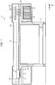
Fig. 1 is an overall configuration diagram of an embodiment of a printing apparatus. -
Fig. 2 is a plan view which schematically illustrates an inner configuration of the printing apparatus ofFig. 1 . -
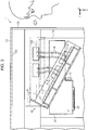
Fig. 3 is a cross-sectional view which illustrates that an attachment section of the printing apparatus ofFig. 1 is at a second position. - With reference to drawings, an embodiment of a printing apparatus will be described. The printing apparatus is, for example, an ink jet printer that performs printing by ejecting ink which is an example of the liquid onto a medium such as a paper sheet.
- As shown in
Fig. 1 , aprinting apparatus 11 includes ahousing 12,legs 13 that support thehousing 12, aprinting section 20, amaintenance mechanism 30, and anattachment section 24 on which aliquid container 23 can be attached. Theprinting section 20, themaintenance mechanism 30, and theattachment section 24 are housed in thehousing 12. Theprinting section 20 includes an ejectinghead 21 to which nozzles 22 (seeFig. 3 ) are open so that liquid is ejected therethrough. Theliquid container 23 is a tank that can store the liquid to be supplied to theprinting section 20. Alternatively, theliquid container 23 may be a cartridge, which is a replaceable container. - The
printing section 20 is configured to perform printing onto amedium 99 while reciprocating in amovement area 14 which extends in a longitudinal direction of thehousing 12. After printing is performed, themedium 99 is transported in a direction Y to the outside of thehousing 12, and is hung in a gravitational direction Z. One and the other ends of themovement area 14 in the longitudinal direction are referred to as afirst end 14f and asecond end 14s, respectively. In the figure, a direction from thefirst end 14f to thesecond end 14s is indicated as a direction X. The direction X, the direction Y, and the gravitational direction Z form a three-axis system. - The
printing apparatus 11 includes aguide shaft 15 that guides movement of theprinting section 20, amedium support section 16 that can support themedium 99, acircuit board 100 which is an example of a component, and anattachment section 40 to which thecircuit board 100 can be attached, which are housed in thehousing 12. Thecircuit board 100 is a control unit that controls constituent elements of theprinting apparatus 11 such as theprinting section 20. - The
medium support section 16 is disposed between thefirst end 14f and thesecond end 14s in the longitudinal direction of themovement area 14. Themedium support section 16 preferably has an end portion extending outside thehousing 12 so as to support themedium 99 which is outputted outside thehousing 12. - When in printing, the
printing section 20 reciprocates between thefirst end 14f and thesecond end 14s of themovement area 14 while traversing themedium support section 16. When not in printing, theprinting section 20 stands-by at a stand-by position which is closer to thesecond end 14s than to themedium support section 16. In this case, theattachment section 40 is preferably disposed at a position closer to thefirst end 14f than to themedium support section 16. Theprinting section 20 shown inFig. 1 is located at the stand-by position. Acap 17 is preferably disposed at the stand-by position so as to cover the nozzles 22 (seeFig. 3 ). - The
maintenance mechanism 30 is disposed, for example, at a position closer to thefirst end 14f than to themedium support section 16. Themaintenance mechanism 30 includes at least one of awiping member 31, asuction mechanism 32, and a wasteliquid receiver 33. Thewiping member 31 wipes foreign substances such as liquid adhered to the ejectinghead 21 while moving relative to the ejectinghead 21. Thesuction mechanism 32 suctions the ejectinghead 21 through thenozzles 22 to thereby purge foreign substances such as air bubbles residing in theprinting section 20. The wasteliquid receiver 33 receives the ejected waste liquid when theprinting section 20 ejects liquid as waste liquid. The wasteliquid receiver 33 may also be disposed at a position between themedium support section 16 and thesecond end 14s. - As shown in
Fig. 2 , one ormore cables 18 are detachably attached to thecircuit board 100. Thecable 18 is an example of a component detachably attached to thecircuit board 100 which is mounted on afixation frame 41. For example, thecable 18 may be a line for transmitting electric power to thecircuit board 100 or may be a line for transmitting a signal to theprinting section 20. Thecable 18 may be a flexible flat cable or a wire harness, which is an assembly of a plurality of lines. - A wall of the
housing 12 which faces theattachment section 40 is preferably aremovable cover 12a. When thecover 12a is removed, theattachment section 40 can be visually observed. Thecover 12a can be disposed on the rear side of thehousing 12 taking the surface of thehousing 12 from which themedium 99 is outputted as the front side. - In
Figs. 2 and3 , the white arrow indicates the gaze of a user looking at theattachment section 40 in thehousing 12 with thecover 12a being removed. InFig. 3 , thehousing 12 is shown with thecover 12a removed. A portion of thehousing 12 from which thecover 12a is removed is an opening 12b. - As shown in
Fig. 3 , theattachment section 40 is movable between a first position (the position indicated by the double-dotted and dashed line) above themovement area 14 and a second position (the position indicated by the solid line) which is at least partially within themovement area 14. Theattachment section 40 is preferably fixed by a fastener such as a screw when located at the first position. In this case, theattachment section 40 moves to the second position by its own weight when released from the fixed state. - The
attachment section 40 preferably includes thefixation frame 41 on which thecircuit board 100 can be mounted. Thefixation frame 41 preferably has anaperture 41a that allows thecable 18 to pass therethrough. Thecable 18 is preferably flexed so as to follow movement of thefixation frame 41. Theattachment section 40 may also include a table 42 for carrying thecircuit board 100. A gap is formed between the table 42 and thefixation frame 41 to promote heat dissipation of thecircuit board 100. Further, a fastener such as a screw can protrude into the gap. - The
attachment section 40 is preferably configured to be tiltable between the first position and the second position. For example, the bottom of thefixation frame 41 is substantially horizontal at the first position, and the bottom of thefixation frame 41 is tilted relative to the horizontal at the second position. When the fixation frame is in the first position, when the end of thefixation frame 41 more spaced from theopening 12b is referred to as a proximal end and the end closer to theopening 12b is referred to as a distal end, thefixation frame 41 is preferably tilted with the distal end moving downward from the first position to the second position. - The
fixation frame 41 can be formed in a plate or box shape. Thefixation frame 41 is disposed to face the inner surface (for example, a ceiling surface 12c) of thehousing 12 when located at the first position so that thecircuit board 100 is protected by thehousing 12. However, when thefixation frame 41 faces the ceiling surface 12c, it is difficult to visually observe thecircuit board 100. Therefore, in the second position, it is preferred that a portion of thefixation frame 41 on which thecircuit board 100 is mounted is oriented to the outside of thehousing 12 to more of an extent than in the first position. - Next, effects and advantages of the
printing apparatus 11 configured as above will be described. Theattachment section 40 is disposed at the first position above themovement area 14 during an operation such as printing in which theprinting section 20 moves. As a result, theprinting section 20 when moving does not come into contact with theattachment section 40. When in maintenance of surroundings of thecircuit board 100, the user stops theprinting section 20 at the stand-by position and removes thecover 12a from thehousing 12. Then, the user moves theattachment section 40 from the first position to the second position. Since theprinting section 20 is located at the stand-by position, it does not come into contact with theattachment section 40 when theattachment section 40 moves. - As the
attachment section 40 moves, the distal end of thefixation frame 41, which is the end closest to the user, comes at a position lower than the proximal end. Accordingly, thecircuit board 100 held by thefixation frame 41 comes to a position that can be easily observed. As a result, a maintenance operation such as inspection of thecircuit board 100 and replacement of thecircuit board 100 can be smoothly performed. The maintenance operation also includes inspection, re-insertion, and replacement of thecable 18. - According to the
printing apparatus 11 of the present embodiment, the following effects can be obtained. - (1) When the
attachment section 40 is located in thehousing 12, thecircuit board 100 is concealed and not easily observed. Therefore, when theattachment section 40 is moved to a position close to theopening 12b, the maintenance operation can be smoothly performed. - (2) Since the
housing 12 is disposed on thelegs 13, thehousing 12 is at a raised position, which causes difficulty in visual observation of thehousing 12. Therefore, when theattachment section 40 is moved to a lower position, the maintenance operation can be smoothly performed. - (3) When the second position of the
attachment section 40 overlaps themovement area 14, a space in thehousing 12 can be efficiently used since the movable range of theattachment section 40 does not need to be reserved. - (4) The
movement area 14 is larger than the movable range of theattachment section 40. Accordingly, a working space for a maintenance operation can be provided around theattachment section 40 in the second position. - (5) When the position at which an attachment operation is performed is easily observed, errors in operation such as erroneous connection of the
cable 18, oblique insertion of thecircuit board 100, and damages due to collision of the components can be reduced. - (6) When the
attachment section 40 is located at a raised position, a step or the like is necessary for smooth operation. Further, use of the step may cause poor footing. However, since theattachment section 40 is moved to a lower position, the operation can be safely performed without using a step. - The above embodiment may be changed as described in the following modified examples. The configurations included in the above embodiment can be combined with the configurations included in the following modified examples as appropriate. Further, each of the configurations included in the following modified examples may be combined as appropriate.
- The
attachment section 24 can be movable. In this case, a component attached to theattachment section 24 may be theliquid container 23 or a waste liquid container that stores waste liquid discharged by a suctioning operation or the like. Theattachment section 24 is preferably configured to move, for example, from the first position which is shown inFig. 1 to a second position lower than the first position. In this configuration, theattachment section 40 may protrude downward from the bottom of thehousing 12. - The
attachment sections - In the
housing 12, theattachment section 24 may be disposed above theprinting section 20 and may be movable between the first position above themovement area 14 and the second position which is at least partially within themovement area 14.
- In the
- The
attachment section 40 or theattachment section 24 may be disposed immediately above themedium support section 16.- Liquid ejected from the
printing section 20 is not limited to ink, and may be, for example, a liquid material which is made by dispersing or mixing a particle of a functional material in liquid. For example, theprinting section 20 may be configured to eject a liquid material which includes dispersed or mixed material such as electrode material or color material (pixel material) used for production of liquid crystal displays, EL (electroluminescence) displays and surface emission displays.
- Liquid ejected from the
- The medium 99 is not limited to a paper sheet, and may be a plastic film or a thin plate, or alternatively, a cloth used in a fabric printing apparatus. Further, the medium 99 may be an article of clothing in any shape such as a T-shirt, or a three-dimensional object such as an article of tableware or stationery in any shape.
- Technical ideas achieved by the above embodiment and modified examples and their advantageous effects will be described below.
- A printing apparatus including a printing section configured to perform printing onto a medium while reciprocating in a movement area, and an attachment section to which a component can be attached, wherein the attachment section is movable between a first position above the movement area and a second position which is at least partially within the movement area.
- With this configuration, contact between the attachment section and the printing section can be avoided by providing the attachment section at the first position during an operation such as printing. As the attachment section is moved from the first position to the second position, the attachment section comes to a lower position. As a result, the attachment section can be easily observed when attaching or detaching a component.
- The printing apparatus according to the
idea 1, wherein the attachment section is configured to be tiltable between the first position and the second position. - With this configuration, as the attachment section is tilted, the visual observation can be effectively improved while reducing the movable range of the attachment section.
- The printing apparatus according to the
idea 1 or 2, including a medium support section that supports the medium, wherein the printing section reciprocates between a first end and a second end of the movement area while traversing the medium support section when in printing, and stands-by at a stand-by position which is closer to the second end than to the medium support section when not in printing, and the attachment section is disposed at a position closer to the first end than to the medium support section. - With this configuration, the printing section stands-by at the stand-by position which is spaced from the attachment section when not in printing. As a result, the attachment section does not come into contact with the printing section when moving to the second position.
- The printing apparatus according to any one of the
ideas 1 to 3, wherein the component is a circuit board, and the attachment section includes a fixation frame which allows the circuit board to be mounted thereon. - With this configuration, since the fixation frame comes to a lower position as the attachment section is moved from the first position to the second position, attachment and detachment of the circuit board can be easily performed.
- The printing apparatus according to any one of the
ideas 1 to 3, wherein the attachment section includes a circuit board and a fixation frame which allows the circuit board to be mounted thereon, and the component is a cable that is detachably attached to the circuit board. - With this configuration, since the fixation frame comes to a lower position as the attachment section is moved from the first position to the second position, the circuit board can be easily observed. As a result, attachment and detachment of the cable to and from the circuit board can be easily performed.
Claims (5)
- A printing apparatus (11) comprising:a printing section (20) configured to perform printing onto a medium (99) while reciprocating in a movement area (14); andan attachment section (40) to which a component (100) can be attached, wherein the attachment section is movable between a first position above the movement area and a second position which is at least partially within the movement area.
- The printing apparatus according to Claim 1, wherein the attachment section is configured to be tiltable between the first position and the second position.
- The printing apparatus according to Claim 1 or Claim 2, comprising a medium support section (16) for supporting the medium, wherein
the printing section is configured to reciprocate between a first end (14f) and a second end (14s) of the movement area while traversing the medium support section when in printing, and to stand by at a stand-by position which is closer to the second end than to the medium support section when not in printing, and
the attachment section is disposed at a position closer to the first end than to the medium support section. - The printing apparatus according to any one of the preceding claims, wherein
the component is a circuit board (100), and
the attachment section includes a fixation frame (41) which allows the circuit board to be mounted thereon. - The printing apparatus according to any one of Claims 1 to 3, wherein
the attachment section (40) includes a circuit board (100) and a fixation frame (41) which allows the circuit board to be mounted thereon, and
the component is a cable (18) that is detachably attached to the circuit board.
Applications Claiming Priority (1)
| Application Number | Priority Date | Filing Date | Title |
|---|---|---|---|
| JP2017057140A JP6922310B2 (en) | 2017-03-23 | 2017-03-23 | Printing equipment |
Publications (2)
| Publication Number | Publication Date |
|---|---|
| EP3378657A1 true EP3378657A1 (en) | 2018-09-26 |
| EP3378657B1 EP3378657B1 (en) | 2020-01-29 |
Family
ID=61691745
Family Applications (1)
| Application Number | Title | Priority Date | Filing Date |
|---|---|---|---|
| EP18162507.0A Active EP3378657B1 (en) | 2017-03-23 | 2018-03-19 | Printing apparatus |
Country Status (4)
| Country | Link |
|---|---|
| US (1) | US10286697B2 (en) |
| EP (1) | EP3378657B1 (en) |
| JP (1) | JP6922310B2 (en) |
| CN (1) | CN108621558B (en) |
Families Citing this family (2)
| Publication number | Priority date | Publication date | Assignee | Title |
|---|---|---|---|---|
| JP7589439B2 (en) * | 2020-02-28 | 2024-11-26 | セイコーエプソン株式会社 | Printing device |
| JP2025062432A (en) * | 2023-10-02 | 2025-04-14 | キヤノン株式会社 | Image forming device |
Citations (6)
| Publication number | Priority date | Publication date | Assignee | Title |
|---|---|---|---|---|
| US5096316A (en) * | 1988-11-18 | 1992-03-17 | Seikosha Co., Ltd. | Serial printer |
| JPH0752377A (en) * | 1993-08-10 | 1995-02-28 | Funai Electric Co Ltd | Inkjet recording apparatus |
| JP2004130622A (en) * | 2002-10-09 | 2004-04-30 | Canon Inc | Inkjet recording device |
| US20080252670A1 (en) * | 2007-04-12 | 2008-10-16 | Labar Daniel Robert | Apparatus for Facilitating Ink Tank/Printhead Replacement In An Imaging Apparatus |
| US20140247304A1 (en) * | 2013-03-04 | 2014-09-04 | Seiko Epson Corporation | Liquid ejecting apparatus |
| JP2016022626A (en) | 2014-07-17 | 2016-02-08 | 株式会社ミマキエンジニアリング | Storage container, connection device and connection method |
Family Cites Families (15)
| Publication number | Priority date | Publication date | Assignee | Title |
|---|---|---|---|---|
| JPS61143154A (en) * | 1984-12-17 | 1986-06-30 | Canon Inc | Thermal transfer type recording apparatus |
| JPS61154879A (en) * | 1984-12-28 | 1986-07-14 | Canon Inc | recording device |
| JPS61175068A (en) * | 1985-01-31 | 1986-08-06 | Canon Inc | Output device |
| JP2854998B2 (en) * | 1991-04-23 | 1999-02-10 | キヤノン株式会社 | Recording device and information processing device |
| JP4251041B2 (en) * | 2002-08-30 | 2009-04-08 | セイコーエプソン株式会社 | Liquid ejector |
| US7438380B2 (en) * | 2005-08-31 | 2008-10-21 | Brother Kogyo Kabushiki Kaisha | Image forming apparatus |
| CN101326062B (en) * | 2005-12-05 | 2011-04-13 | 西尔弗布鲁克研究有限公司 | Printhead Cartridge Engagement with Power Conditioning |
| JP4420010B2 (en) * | 2006-11-06 | 2010-02-24 | 船井電機株式会社 | Printer |
| JP2010064264A (en) * | 2008-09-08 | 2010-03-25 | Ricoh Co Ltd | Image forming apparatus |
| JP5274310B2 (en) | 2009-03-09 | 2013-08-28 | キヤノン株式会社 | Image forming apparatus |
| JP5906622B2 (en) * | 2011-09-09 | 2016-04-20 | ブラザー工業株式会社 | Inkjet recording device |
| JP5542783B2 (en) * | 2011-11-15 | 2014-07-09 | シャープ株式会社 | Electric cable connecting device and image forming apparatus |
| US8708469B2 (en) * | 2012-01-12 | 2014-04-29 | Seiko Epson Corporation | Cartridge and printing material supply system |
| JP6255601B2 (en) * | 2013-03-27 | 2018-01-10 | セイコーエプソン株式会社 | Image recording device |
| US9555633B2 (en) * | 2014-10-09 | 2017-01-31 | Ricoh Company, Ltd. | Replay unit for waste liquid container and image forming apparatus incorporating the relay unit |
-
2017
- 2017-03-23 JP JP2017057140A patent/JP6922310B2/en active Active
-
2018
- 2018-03-12 US US15/918,876 patent/US10286697B2/en active Active
- 2018-03-19 EP EP18162507.0A patent/EP3378657B1/en active Active
- 2018-03-22 CN CN201810243294.9A patent/CN108621558B/en active Active
Patent Citations (6)
| Publication number | Priority date | Publication date | Assignee | Title |
|---|---|---|---|---|
| US5096316A (en) * | 1988-11-18 | 1992-03-17 | Seikosha Co., Ltd. | Serial printer |
| JPH0752377A (en) * | 1993-08-10 | 1995-02-28 | Funai Electric Co Ltd | Inkjet recording apparatus |
| JP2004130622A (en) * | 2002-10-09 | 2004-04-30 | Canon Inc | Inkjet recording device |
| US20080252670A1 (en) * | 2007-04-12 | 2008-10-16 | Labar Daniel Robert | Apparatus for Facilitating Ink Tank/Printhead Replacement In An Imaging Apparatus |
| US20140247304A1 (en) * | 2013-03-04 | 2014-09-04 | Seiko Epson Corporation | Liquid ejecting apparatus |
| JP2016022626A (en) | 2014-07-17 | 2016-02-08 | 株式会社ミマキエンジニアリング | Storage container, connection device and connection method |
Also Published As
| Publication number | Publication date |
|---|---|
| US10286697B2 (en) | 2019-05-14 |
| EP3378657B1 (en) | 2020-01-29 |
| CN108621558A (en) | 2018-10-09 |
| CN108621558B (en) | 2021-11-30 |
| JP2018158510A (en) | 2018-10-11 |
| US20180272771A1 (en) | 2018-09-27 |
| JP6922310B2 (en) | 2021-08-18 |
Similar Documents
| Publication | Publication Date | Title |
|---|---|---|
| US11097562B2 (en) | Printing apparatus | |
| EP3162571A1 (en) | Liquid ejecting device and head | |
| US10245838B2 (en) | Liquid ejecting apparatus | |
| US10022972B2 (en) | Waste liquid container and attachment | |
| EP2857212B1 (en) | Image forming apparatus | |
| EP2233295B1 (en) | Cleaner unit, printing apparatus, and method to clean a printing apparatus | |
| EP3378657B1 (en) | Printing apparatus | |
| JP7115225B2 (en) | Device for ejecting liquid | |
| US10173427B2 (en) | Recording apparatus | |
| CN104228348B (en) | Maintenance unit and liquid injection apparatus | |
| JP6551444B2 (en) | Printing device | |
| US9254670B2 (en) | Liquid ejecting apparatus, adapter, and liquid supply system | |
| JP2021138092A (en) | Liquid discharge device and support member for printing medium | |
| EP3530464B1 (en) | Liquid droplet discharge device | |
| JP2020006631A (en) | Printing equipment | |
| US20180043693A1 (en) | Liquid supply device and liquid ejecting apparatus | |
| WO2013128924A1 (en) | Liquid-ejection device | |
| US8047628B2 (en) | Printing apparatus | |
| US11214071B2 (en) | Printer and ink supply unit | |
| US20150375510A1 (en) | Recording apparatus | |
| US10059117B2 (en) | Liquid ejecting apparatus and liquid supply method of liquid ejecting apparatus | |
| JP2014034182A (en) | Liquid injection device | |
| CN108215505B (en) | liquid ejection device | |
| JP2014104708A (en) | Liquid jetting device, liquid jetting method |
Legal Events
| Date | Code | Title | Description |
|---|---|---|---|
| PUAI | Public reference made under article 153(3) epc to a published international application that has entered the european phase |
Free format text: ORIGINAL CODE: 0009012 |
|
| STAA | Information on the status of an ep patent application or granted ep patent |
Free format text: STATUS: THE APPLICATION HAS BEEN PUBLISHED |
|
| AK | Designated contracting states |
Kind code of ref document: A1 Designated state(s): AL AT BE BG CH CY CZ DE DK EE ES FI FR GB GR HR HU IE IS IT LI LT LU LV MC MK MT NL NO PL PT RO RS SE SI SK SM TR |
|
| AX | Request for extension of the european patent |
Extension state: BA ME |
|
| STAA | Information on the status of an ep patent application or granted ep patent |
Free format text: STATUS: REQUEST FOR EXAMINATION WAS MADE |
|
| 17P | Request for examination filed |
Effective date: 20190326 |
|
| RBV | Designated contracting states (corrected) |
Designated state(s): AL AT BE BG CH CY CZ DE DK EE ES FI FR GB GR HR HU IE IS IT LI LT LU LV MC MK MT NL NO PL PT RO RS SE SI SK SM TR |
|
| GRAP | Despatch of communication of intention to grant a patent |
Free format text: ORIGINAL CODE: EPIDOSNIGR1 |
|
| STAA | Information on the status of an ep patent application or granted ep patent |
Free format text: STATUS: GRANT OF PATENT IS INTENDED |
|
| INTG | Intention to grant announced |
Effective date: 20190911 |
|
| GRAS | Grant fee paid |
Free format text: ORIGINAL CODE: EPIDOSNIGR3 |
|
| GRAA | (expected) grant |
Free format text: ORIGINAL CODE: 0009210 |
|
| STAA | Information on the status of an ep patent application or granted ep patent |
Free format text: STATUS: THE PATENT HAS BEEN GRANTED |
|
| AK | Designated contracting states |
Kind code of ref document: B1 Designated state(s): AL AT BE BG CH CY CZ DE DK EE ES FI FR GB GR HR HU IE IS IT LI LT LU LV MC MK MT NL NO PL PT RO RS SE SI SK SM TR |
|
| REG | Reference to a national code |
Ref country code: GB Ref legal event code: FG4D |
|
| REG | Reference to a national code |
Ref country code: CH Ref legal event code: EP |
|
| REG | Reference to a national code |
Ref country code: AT Ref legal event code: REF Ref document number: 1228212 Country of ref document: AT Kind code of ref document: T Effective date: 20200215 |
|
| REG | Reference to a national code |
Ref country code: IE Ref legal event code: FG4D |
|
| REG | Reference to a national code |
Ref country code: DE Ref legal event code: R096 Ref document number: 602018002170 Country of ref document: DE |
|
| REG | Reference to a national code |
Ref country code: NL Ref legal event code: MP Effective date: 20200129 |
|
| PG25 | Lapsed in a contracting state [announced via postgrant information from national office to epo] |
Ref country code: PT Free format text: LAPSE BECAUSE OF FAILURE TO SUBMIT A TRANSLATION OF THE DESCRIPTION OR TO PAY THE FEE WITHIN THE PRESCRIBED TIME-LIMIT Effective date: 20200621 Ref country code: FI Free format text: LAPSE BECAUSE OF FAILURE TO SUBMIT A TRANSLATION OF THE DESCRIPTION OR TO PAY THE FEE WITHIN THE PRESCRIBED TIME-LIMIT Effective date: 20200129 Ref country code: NO Free format text: LAPSE BECAUSE OF FAILURE TO SUBMIT A TRANSLATION OF THE DESCRIPTION OR TO PAY THE FEE WITHIN THE PRESCRIBED TIME-LIMIT Effective date: 20200429 Ref country code: RS Free format text: LAPSE BECAUSE OF FAILURE TO SUBMIT A TRANSLATION OF THE DESCRIPTION OR TO PAY THE FEE WITHIN THE PRESCRIBED TIME-LIMIT Effective date: 20200129 |
|
| REG | Reference to a national code |
Ref country code: LT Ref legal event code: MG4D |
|
| PG25 | Lapsed in a contracting state [announced via postgrant information from national office to epo] |
Ref country code: GR Free format text: LAPSE BECAUSE OF FAILURE TO SUBMIT A TRANSLATION OF THE DESCRIPTION OR TO PAY THE FEE WITHIN THE PRESCRIBED TIME-LIMIT Effective date: 20200430 Ref country code: BG Free format text: LAPSE BECAUSE OF FAILURE TO SUBMIT A TRANSLATION OF THE DESCRIPTION OR TO PAY THE FEE WITHIN THE PRESCRIBED TIME-LIMIT Effective date: 20200429 Ref country code: SE Free format text: LAPSE BECAUSE OF FAILURE TO SUBMIT A TRANSLATION OF THE DESCRIPTION OR TO PAY THE FEE WITHIN THE PRESCRIBED TIME-LIMIT Effective date: 20200129 Ref country code: LV Free format text: LAPSE BECAUSE OF FAILURE TO SUBMIT A TRANSLATION OF THE DESCRIPTION OR TO PAY THE FEE WITHIN THE PRESCRIBED TIME-LIMIT Effective date: 20200129 Ref country code: IS Free format text: LAPSE BECAUSE OF FAILURE TO SUBMIT A TRANSLATION OF THE DESCRIPTION OR TO PAY THE FEE WITHIN THE PRESCRIBED TIME-LIMIT Effective date: 20200529 Ref country code: HR Free format text: LAPSE BECAUSE OF FAILURE TO SUBMIT A TRANSLATION OF THE DESCRIPTION OR TO PAY THE FEE WITHIN THE PRESCRIBED TIME-LIMIT Effective date: 20200129 |
|
| PG25 | Lapsed in a contracting state [announced via postgrant information from national office to epo] |
Ref country code: NL Free format text: LAPSE BECAUSE OF FAILURE TO SUBMIT A TRANSLATION OF THE DESCRIPTION OR TO PAY THE FEE WITHIN THE PRESCRIBED TIME-LIMIT Effective date: 20200129 |
|
| PG25 | Lapsed in a contracting state [announced via postgrant information from national office to epo] |
Ref country code: DK Free format text: LAPSE BECAUSE OF FAILURE TO SUBMIT A TRANSLATION OF THE DESCRIPTION OR TO PAY THE FEE WITHIN THE PRESCRIBED TIME-LIMIT Effective date: 20200129 Ref country code: LT Free format text: LAPSE BECAUSE OF FAILURE TO SUBMIT A TRANSLATION OF THE DESCRIPTION OR TO PAY THE FEE WITHIN THE PRESCRIBED TIME-LIMIT Effective date: 20200129 Ref country code: MC Free format text: LAPSE BECAUSE OF FAILURE TO SUBMIT A TRANSLATION OF THE DESCRIPTION OR TO PAY THE FEE WITHIN THE PRESCRIBED TIME-LIMIT Effective date: 20200129 Ref country code: ES Free format text: LAPSE BECAUSE OF FAILURE TO SUBMIT A TRANSLATION OF THE DESCRIPTION OR TO PAY THE FEE WITHIN THE PRESCRIBED TIME-LIMIT Effective date: 20200129 Ref country code: CZ Free format text: LAPSE BECAUSE OF FAILURE TO SUBMIT A TRANSLATION OF THE DESCRIPTION OR TO PAY THE FEE WITHIN THE PRESCRIBED TIME-LIMIT Effective date: 20200129 Ref country code: SK Free format text: LAPSE BECAUSE OF FAILURE TO SUBMIT A TRANSLATION OF THE DESCRIPTION OR TO PAY THE FEE WITHIN THE PRESCRIBED TIME-LIMIT Effective date: 20200129 Ref country code: RO Free format text: LAPSE BECAUSE OF FAILURE TO SUBMIT A TRANSLATION OF THE DESCRIPTION OR TO PAY THE FEE WITHIN THE PRESCRIBED TIME-LIMIT Effective date: 20200129 Ref country code: EE Free format text: LAPSE BECAUSE OF FAILURE TO SUBMIT A TRANSLATION OF THE DESCRIPTION OR TO PAY THE FEE WITHIN THE PRESCRIBED TIME-LIMIT Effective date: 20200129 Ref country code: SM Free format text: LAPSE BECAUSE OF FAILURE TO SUBMIT A TRANSLATION OF THE DESCRIPTION OR TO PAY THE FEE WITHIN THE PRESCRIBED TIME-LIMIT Effective date: 20200129 |
|
| REG | Reference to a national code |
Ref country code: DE Ref legal event code: R097 Ref document number: 602018002170 Country of ref document: DE |
|
| REG | Reference to a national code |
Ref country code: AT Ref legal event code: MK05 Ref document number: 1228212 Country of ref document: AT Kind code of ref document: T Effective date: 20200129 |
|
| PLBE | No opposition filed within time limit |
Free format text: ORIGINAL CODE: 0009261 |
|
| STAA | Information on the status of an ep patent application or granted ep patent |
Free format text: STATUS: NO OPPOSITION FILED WITHIN TIME LIMIT |
|
| REG | Reference to a national code |
Ref country code: BE Ref legal event code: MM Effective date: 20200331 |
|
| PG25 | Lapsed in a contracting state [announced via postgrant information from national office to epo] |
Ref country code: LU Free format text: LAPSE BECAUSE OF NON-PAYMENT OF DUE FEES Effective date: 20200319 |
|
| 26N | No opposition filed |
Effective date: 20201030 |
|
| PG25 | Lapsed in a contracting state [announced via postgrant information from national office to epo] |
Ref country code: IT Free format text: LAPSE BECAUSE OF FAILURE TO SUBMIT A TRANSLATION OF THE DESCRIPTION OR TO PAY THE FEE WITHIN THE PRESCRIBED TIME-LIMIT Effective date: 20200129 Ref country code: IE Free format text: LAPSE BECAUSE OF NON-PAYMENT OF DUE FEES Effective date: 20200319 Ref country code: AT Free format text: LAPSE BECAUSE OF FAILURE TO SUBMIT A TRANSLATION OF THE DESCRIPTION OR TO PAY THE FEE WITHIN THE PRESCRIBED TIME-LIMIT Effective date: 20200129 |
|
| PG25 | Lapsed in a contracting state [announced via postgrant information from national office to epo] |
Ref country code: SI Free format text: LAPSE BECAUSE OF FAILURE TO SUBMIT A TRANSLATION OF THE DESCRIPTION OR TO PAY THE FEE WITHIN THE PRESCRIBED TIME-LIMIT Effective date: 20200129 Ref country code: BE Free format text: LAPSE BECAUSE OF NON-PAYMENT OF DUE FEES Effective date: 20200331 Ref country code: PL Free format text: LAPSE BECAUSE OF FAILURE TO SUBMIT A TRANSLATION OF THE DESCRIPTION OR TO PAY THE FEE WITHIN THE PRESCRIBED TIME-LIMIT Effective date: 20200129 |
|
| REG | Reference to a national code |
Ref country code: CH Ref legal event code: PL |
|
| PG25 | Lapsed in a contracting state [announced via postgrant information from national office to epo] |
Ref country code: LI Free format text: LAPSE BECAUSE OF NON-PAYMENT OF DUE FEES Effective date: 20210331 Ref country code: CH Free format text: LAPSE BECAUSE OF NON-PAYMENT OF DUE FEES Effective date: 20210331 |
|
| PG25 | Lapsed in a contracting state [announced via postgrant information from national office to epo] |
Ref country code: TR Free format text: LAPSE BECAUSE OF FAILURE TO SUBMIT A TRANSLATION OF THE DESCRIPTION OR TO PAY THE FEE WITHIN THE PRESCRIBED TIME-LIMIT Effective date: 20200129 Ref country code: MT Free format text: LAPSE BECAUSE OF FAILURE TO SUBMIT A TRANSLATION OF THE DESCRIPTION OR TO PAY THE FEE WITHIN THE PRESCRIBED TIME-LIMIT Effective date: 20200129 Ref country code: CY Free format text: LAPSE BECAUSE OF FAILURE TO SUBMIT A TRANSLATION OF THE DESCRIPTION OR TO PAY THE FEE WITHIN THE PRESCRIBED TIME-LIMIT Effective date: 20200129 |
|
| PG25 | Lapsed in a contracting state [announced via postgrant information from national office to epo] |
Ref country code: MK Free format text: LAPSE BECAUSE OF FAILURE TO SUBMIT A TRANSLATION OF THE DESCRIPTION OR TO PAY THE FEE WITHIN THE PRESCRIBED TIME-LIMIT Effective date: 20200129 Ref country code: AL Free format text: LAPSE BECAUSE OF FAILURE TO SUBMIT A TRANSLATION OF THE DESCRIPTION OR TO PAY THE FEE WITHIN THE PRESCRIBED TIME-LIMIT Effective date: 20200129 |
|
| GBPC | Gb: european patent ceased through non-payment of renewal fee |
Effective date: 20220319 |
|
| PG25 | Lapsed in a contracting state [announced via postgrant information from national office to epo] |
Ref country code: GB Free format text: LAPSE BECAUSE OF NON-PAYMENT OF DUE FEES Effective date: 20220319 |
|
| PGFP | Annual fee paid to national office [announced via postgrant information from national office to epo] |
Ref country code: DE Payment date: 20240130 Year of fee payment: 7 |
|
| PGFP | Annual fee paid to national office [announced via postgrant information from national office to epo] |
Ref country code: FR Payment date: 20240213 Year of fee payment: 7 |
|
| REG | Reference to a national code |
Ref country code: DE Ref legal event code: R119 Ref document number: 602018002170 Country of ref document: DE |
|
| PG25 | Lapsed in a contracting state [announced via postgrant information from national office to epo] |
Ref country code: DE Free format text: LAPSE BECAUSE OF NON-PAYMENT OF DUE FEES Effective date: 20251001 |
|
| PG25 | Lapsed in a contracting state [announced via postgrant information from national office to epo] |
Ref country code: FR Free format text: LAPSE BECAUSE OF NON-PAYMENT OF DUE FEES Effective date: 20250331 |