EP3378629A1 - Recoater for additive layer manufacture - Google Patents
Recoater for additive layer manufacture Download PDFInfo
- Publication number
- EP3378629A1 EP3378629A1 EP18159225.4A EP18159225A EP3378629A1 EP 3378629 A1 EP3378629 A1 EP 3378629A1 EP 18159225 A EP18159225 A EP 18159225A EP 3378629 A1 EP3378629 A1 EP 3378629A1
- Authority
- EP
- European Patent Office
- Prior art keywords
- additive layer
- manufacturing apparatus
- layer manufacturing
- doctor blade
- air supply
- Prior art date
- Legal status (The legal status is an assumption and is not a legal conclusion. Google has not performed a legal analysis and makes no representation as to the accuracy of the status listed.)
- Granted
Links
Images


Classifications
-
- B—PERFORMING OPERATIONS; TRANSPORTING
- B29—WORKING OF PLASTICS; WORKING OF SUBSTANCES IN A PLASTIC STATE IN GENERAL
- B29C—SHAPING OR JOINING OF PLASTICS; SHAPING OF MATERIAL IN A PLASTIC STATE, NOT OTHERWISE PROVIDED FOR; AFTER-TREATMENT OF THE SHAPED PRODUCTS, e.g. REPAIRING
- B29C64/00—Additive manufacturing, i.e. manufacturing of three-dimensional [3D] objects by additive deposition, additive agglomeration or additive layering, e.g. by 3D printing, stereolithography or selective laser sintering
- B29C64/20—Apparatus for additive manufacturing; Details thereof or accessories therefor
- B29C64/205—Means for applying layers
- B29C64/214—Doctor blades
-
- B—PERFORMING OPERATIONS; TRANSPORTING
- B05—SPRAYING OR ATOMISING IN GENERAL; APPLYING FLUENT MATERIALS TO SURFACES, IN GENERAL
- B05C—APPARATUS FOR APPLYING FLUENT MATERIALS TO SURFACES, IN GENERAL
- B05C11/00—Component parts, details or accessories not specifically provided for in groups B05C1/00 - B05C9/00
- B05C11/02—Apparatus for spreading or distributing liquids or other fluent materials already applied to a surface ; Controlling means therefor; Control of the thickness of a coating by spreading or distributing liquids or other fluent materials already applied to the coated surface
- B05C11/04—Apparatus for spreading or distributing liquids or other fluent materials already applied to a surface ; Controlling means therefor; Control of the thickness of a coating by spreading or distributing liquids or other fluent materials already applied to the coated surface with blades
- B05C11/045—Apparatus for spreading or distributing liquids or other fluent materials already applied to a surface ; Controlling means therefor; Control of the thickness of a coating by spreading or distributing liquids or other fluent materials already applied to the coated surface with blades characterised by the blades themselves
-
- B—PERFORMING OPERATIONS; TRANSPORTING
- B05—SPRAYING OR ATOMISING IN GENERAL; APPLYING FLUENT MATERIALS TO SURFACES, IN GENERAL
- B05C—APPARATUS FOR APPLYING FLUENT MATERIALS TO SURFACES, IN GENERAL
- B05C11/00—Component parts, details or accessories not specifically provided for in groups B05C1/00 - B05C9/00
- B05C11/02—Apparatus for spreading or distributing liquids or other fluent materials already applied to a surface ; Controlling means therefor; Control of the thickness of a coating by spreading or distributing liquids or other fluent materials already applied to the coated surface
- B05C11/06—Apparatus for spreading or distributing liquids or other fluent materials already applied to a surface ; Controlling means therefor; Control of the thickness of a coating by spreading or distributing liquids or other fluent materials already applied to the coated surface with a blast of gas or vapour
-
- B—PERFORMING OPERATIONS; TRANSPORTING
- B29—WORKING OF PLASTICS; WORKING OF SUBSTANCES IN A PLASTIC STATE IN GENERAL
- B29C—SHAPING OR JOINING OF PLASTICS; SHAPING OF MATERIAL IN A PLASTIC STATE, NOT OTHERWISE PROVIDED FOR; AFTER-TREATMENT OF THE SHAPED PRODUCTS, e.g. REPAIRING
- B29C64/00—Additive manufacturing, i.e. manufacturing of three-dimensional [3D] objects by additive deposition, additive agglomeration or additive layering, e.g. by 3D printing, stereolithography or selective laser sintering
- B29C64/10—Processes of additive manufacturing
- B29C64/141—Processes of additive manufacturing using only solid materials
- B29C64/153—Processes of additive manufacturing using only solid materials using layers of powder being selectively joined, e.g. by selective laser sintering or melting
-
- B—PERFORMING OPERATIONS; TRANSPORTING
- B33—ADDITIVE MANUFACTURING TECHNOLOGY
- B33Y—ADDITIVE MANUFACTURING, i.e. MANUFACTURING OF THREE-DIMENSIONAL [3D] OBJECTS BY ADDITIVE DEPOSITION, ADDITIVE AGGLOMERATION OR ADDITIVE LAYERING, e.g. BY 3D PRINTING, STEREOLITHOGRAPHY OR SELECTIVE LASER SINTERING
- B33Y30/00—Apparatus for additive manufacturing; Details thereof or accessories therefor
-
- B—PERFORMING OPERATIONS; TRANSPORTING
- B33—ADDITIVE MANUFACTURING TECHNOLOGY
- B33Y—ADDITIVE MANUFACTURING, i.e. MANUFACTURING OF THREE-DIMENSIONAL [3D] OBJECTS BY ADDITIVE DEPOSITION, ADDITIVE AGGLOMERATION OR ADDITIVE LAYERING, e.g. BY 3D PRINTING, STEREOLITHOGRAPHY OR SELECTIVE LASER SINTERING
- B33Y10/00—Processes of additive manufacturing
Definitions
- the invention relates to additive layer manufacturing methods and apparatus. More particularly, the invention concerns a re-coater device (sometimes known as a "doctor blade") for use in an additive layer manufacturing method.
- a re-coater device sometimes known as a "doctor blade”
- additive layer manufacturing methods are known. Broadly, such methods involve selected regions within a fluid mass of material being processed across a number of sequential layers to cause local solidification of the material. The sequential layers are built up to form a three dimensional solid object within the fluid mass.
- Additive layer manufacturing methods can be broadly divided into two groups.
- material is deposited sequentially in patterned layers, the pattern of each layer representing a two dimensional cross section of a three dimensional shape of an object. As each layer is deposited atop a previous layer, a three dimensional object is built. Examples of this group of methods include; direct energy deposition (where focussed thermal energy is used to fuse materials as they are being deposited), material extrusion (where an extrusion head moves in a pattern selectively dispensing material through an orifice as it travels) and sheet lamination (where sheets of material already defining a two-dimensional pattern are bonded in sequence to build up the three dimensional object.)
- the process starts with a bulk mass which may, for example, be a bed of powdered material such as a ceramic, a ferrous alloy or a non-ferrous alloy, or a vat of liquid typically comprising a photopolymer. Regions within the mass are selectively treated, for example by melting, sintering, photochemical reaction or interaction with a chemical bonding agent, to solidify.
- the untreated material remains in a layer as the next layer is formed.
- Surplus (untreated) material may be removed when the three dimensional build is complete, through it is also known for surplus material sometimes to be contained within cavities of the three-dimensional object.
- a layer of untreated material may be deposited onto an already treated layer by dispersal from a hopper or by dipping the treated layer below the surface of the untreated material.
- the thickness and consistency of thickness of each layer to be treated must be carefully controlled. This is conventionally achieved by positioning a top surface a fixed distance from the tip of a "doctor blade" which is then skimmed across a top surface of the material to level out the top surface.
- doctor blade In its simplest form the doctor blade is a straight-edged, rigid blade which is skimmed across the material surface gradually pushing away any excess from the newly added material layer.
- the straight edged, rigid blade may comprise a hollow through which a vacuum can be applied. The blade is positioned a small distance from the required top surface level. Rather than push material away, such a device sucks excess material into the hollow as it passes across the surface. In regions where there is insufficient material remaining at the top surface, the vacuum effect is arrested and material is drawn from the hollow back onto the surface.
- the material to be treated is viscous
- EP17150873 describes a doctor blade which is configured to flex as it passes over a surface layer.
- an additive layer manufacturing apparatus comprising a doctor blade having a tip which, in use, is arranged proximal to a material layer to be recoated during an additive layer manufacturing method, the doctor blade having a cavity with an inlet and an outlet, the outlet located at the tip and the inlet connectable to an air supply whereby air can be directed through the cavity to the outlet and onto the material layer.
- the air supply may be a compressed air supply.
- the apparatus may further include a flow control device adjustable to vary the velocity and or pressure of the directed air supply.
- the apparatus may further include a temperature control device for adjusting and or maintaining the temperature of the compressed air supply.
- the blade may include features downstream of the outlet configured to control and/or direct air exiting the outlet. Without limitation, such features may include a grid, one or more nozzles, differently directed channels or the like. In an option, the blade tip may be tapered to provide a converging or diverging outlet.
- multiple doctor blades are provided.
- individual blades of the multiple doctor blades may have a different configuration to others of the multiple doctor blades.
- multiple blades may have the same structure but air supply to each is individually controllable.
- individual blades may have individual supply lines and any given supply line may include a flow control device which is adjustable independently of a flow control device in another supply line.
- the doctor blade may be flexible.
- the doctor blade may have an associated flexible element arranged to follow the tip of the doctor blade across the material layer to be recoated.
- the flexible doctor blade or flexible element may be configured to flex when drawn across the material layer in a first direction but inflexible when drawn across the material layer in a second direction which is opposite to the first direction.
- the apparatus may include a build platform in an X-Y plane and an indexing device for moving the blade in a direction Z, orthogonal to the X-Y plane.
- the apparatus may include a build platform in an X-Y plane and an indexing device for moving the build platform in a direction Z, orthogonal to the X-Y plane.
- the additive layer manufacturing apparatus may include a vat for containing a liquid material from which a 3 dimensional product is to be built and a device for initiating polymerisation of molecules in the liquid material.
- the device for initiating polymerisation may comprise a focusable light source in the ultraviolet to visible region of the electromagnetic spectrum and a transport mechanism for moving the source across a section of the liquid.
- the additive layer manufacturing apparatus may include a container for a powdered material from which a 3 dimensional product is to be built and a device for initiating fusion of the powder.
- the device for initiating fusion of the powder may, for example, be a laser or an electron beam.
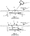
- an additive layer manufacturing apparatus comprises a vat 1 for containing a resin 2.
- a light source 3 is arranged to selectively focus on regions within layers of the resin 2 to initiate photo-polymerisation and build a 3 dimensional body of which a first layer 4 is shown.
- the first layer 4 is built on a build platform 5 which can be moved an upward and downward as represented by the two headed arrow beneath the build platform 5 in the Figure.
- the figure shows the top of the layer 4 just below the surface of the resin 6.
- the surface of the resin is substantially flat. This is typical at commencement of the additive layer manufacture and at a point where movement of the platform 5 has been arrested for some time.
- To build a second layer on to the first layer 4 the platform 5 is dropped into the resin 2 and then raised back to a surface level. This is sometimes termed "deep dipping".
- Figure 2 illustrates the apparatus of Figure 1 immediately after deep dipping.
- a second layer 9 sits on top surface 4a of the first layer 4. Due to viscosity and surface tension in the resin 2 a mound 8 of resin is formed on the surface 9a of the second layer 9. There then follows a waiting period while resin the mound 8 redistributes forming a flatter layer. Where the resin 2 is highly viscous, this can significantly delay the manufacture a body.
- the doctor blade 7 can be swept across the surface 6 to level the mound 8, however, when the build is only a few layers thick, this sweeping motion has an associated risk of stressing the build with a consequence of possible structural damage to the body.
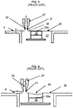
- the vacuum doctor blade blade 37 is characterised by a cavity 30 extending from a tip 31 of the blade.
- the cavity 30 is connected to a suction device which removes air from the cavity 30 (as represented by the grey arrow above the blade) creating a vacuum effect at the tip 31.
- the tip 31 of vacuum doctor blade 37 is spaced a small distance d from the surface 36 of the resin 32. The distance is typically less than the thickness of a build layer. Since the tip is not directly contacting the surface 36, stress on the build is reduced compared to the arrangement of Figures 1 and 2 .
- the vacuum doctor blade 37 has just made a pass over layer 39.
- the surface 39a of the already formed layer 39 is lowered beneath the resin surface 36 by a distance equating to the desired layer thickness.
- a dip 40 results in the resin surface 36.
- the vacuum doctor blade 37 is swept in a reverse direction back over the surface layer 36.
- suction to the cavity 30 is ceased and consequently, as the tip 31 passes over dip 40, resin is released from the cavity 30 into the dip 40.
- Excess resin is now left on the surface 39a due to the stand-off height between the vacuum doctor blade 37 and the resin surface 36. This then requires a wait time to drain back off the surface 39a of the already formed layer 39.
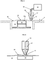
- FIG. 5 illustrates an embodiment of the invention of an additive layer manufacturing apparatus in accordance with the invention.
- the apparatus is shown at a point in the manufacture when a recently polymerised layer 59 has just been dipped in the resin 52 and raised back to the resin surface level 56 in a similar manner as described in relation to Figure 2 .
- a mound 58 is formed on the surface 59a of the polymerised layer 59.
- the vacuum blade of this apparatus has a cavity 50 passing through the doctor blade 57.
- the cavity has an outlet at a tip 51 of the doctor blade 57.
- a conduit 60 connects the cavity 50 to an air supply 53 which forces air through the conduit 60 and the cavity 50 towards the surface 56 of the resin.
- the tip 51 of the blade is positioned a small distance d from the surface level 56 of the resin 52 such that there is no direct contact between the two.
- FIGS 7 8 and 9 illustrate optional adaptations of the tip 51 to control flow of air exiting at the tip 51.
- Figure 7 shows a section and an end view of a first optional adaptation of the doctor blade.
- the cavity 50 has convergent walls 61 towards the tip 51 resulting in a narrowed slot 62 in the tip.
- Figure 8 shows a section and an end view of a second optional adaptation of the doctor blade. As can be seen the tip 51 end of the cavity 50 is covered by a grid 63.
- Figure 9 shows a section and an end view of a third optional adaptation of the doctor blade.
- the tip 51 comprises a wall through which differently directed channels 64, 65 are provided.
- Figure 10 shows a section and an end view of a fourth optional adaptation of the doctor blade.
- the doctor blade 57 of this embodiment includes a follow blade 66 on one side of the doctor blade 57.
- the follower blade 66 is flexible as represented by the dotted outline and curved arrow in the Figure.
- a tip of the flexible follower blade 66 extends beyond the tip 51 of the of the doctor blade 57 by a distance d.
- the tip of the follow blade contacts the surface of the resin.
- the follow blade 66 is swept across the surface, it flexes thereby reducing stress on the surface layer.
- doctor blade 57 and associated air supply 53 may also be used to fill efficiently a dip in a resin surface.
- the apparatus of the invention may be applied to other additive layer manufacturing methods, for example powder bed ALM.
Landscapes
- Chemical & Material Sciences (AREA)
- Engineering & Computer Science (AREA)
- Materials Engineering (AREA)
- Manufacturing & Machinery (AREA)
- Physics & Mathematics (AREA)
- Optics & Photonics (AREA)
- Mechanical Engineering (AREA)
Abstract
Description
- The invention relates to additive layer manufacturing methods and apparatus. More particularly, the invention concerns a re-coater device (sometimes known as a "doctor blade") for use in an additive layer manufacturing method.
- Additive layer manufacturing (ALM) methods are known. Broadly, such methods involve selected regions within a fluid mass of material being processed across a number of sequential layers to cause local solidification of the material. The sequential layers are built up to form a three dimensional solid object within the fluid mass.
- Additive layer manufacturing methods can be broadly divided into two groups. In a first group, material is deposited sequentially in patterned layers, the pattern of each layer representing a two dimensional cross section of a three dimensional shape of an object. As each layer is deposited atop a previous layer, a three dimensional object is built. Examples of this group of methods include; direct energy deposition (where focussed thermal energy is used to fuse materials as they are being deposited), material extrusion (where an extrusion head moves in a pattern selectively dispensing material through an orifice as it travels) and sheet lamination (where sheets of material already defining a two-dimensional pattern are bonded in sequence to build up the three dimensional object.)
- In the second group, the process starts with a bulk mass which may, for example, be a bed of powdered material such as a ceramic, a ferrous alloy or a non-ferrous alloy, or a vat of liquid typically comprising a photopolymer. Regions within the mass are selectively treated, for example by melting, sintering, photochemical reaction or interaction with a chemical bonding agent, to solidify. However unlike with the first group, the untreated material remains in a layer as the next layer is formed. Surplus (untreated) material may be removed when the three dimensional build is complete, through it is also known for surplus material sometimes to be contained within cavities of the three-dimensional object.
- Within the second group of ALM methods, a layer of untreated material may be deposited onto an already treated layer by dispersal from a hopper or by dipping the treated layer below the surface of the untreated material. For the three-dimensional shape to be properly controlled, the thickness and consistency of thickness of each layer to be treated must be carefully controlled. This is conventionally achieved by positioning a top surface a fixed distance from the tip of a "doctor blade" which is then skimmed across a top surface of the material to level out the top surface.
- Various forms of doctor blade are known. In its simplest form the doctor blade is a straight-edged, rigid blade which is skimmed across the material surface gradually pushing away any excess from the newly added material layer. In a more advanced form, the straight edged, rigid blade may comprise a hollow through which a vacuum can be applied. The blade is positioned a small distance from the required top surface level. Rather than push material away, such a device sucks excess material into the hollow as it passes across the surface. In regions where there is insufficient material remaining at the top surface, the vacuum effect is arrested and material is drawn from the hollow back onto the surface. Where the material to be treated is viscous, there may be a waiting time between recoats while the viscous top surface drains and settles. In some cases highly viscous materials may not drain and settle resulting in the top surface rising above the desired height and a consequent, detrimental effect on the quality of the component.
- The Applicant's previously filed European Patent Application no.
EP17150873 - In accordance with the present invention there is provided an additive layer manufacturing apparatus comprising a doctor blade having a tip which, in use, is arranged proximal to a material layer to be recoated during an additive layer manufacturing method, the doctor blade having a cavity with an inlet and an outlet, the outlet located at the tip and the inlet connectable to an air supply whereby air can be directed through the cavity to the outlet and onto the material layer.
- The air supply may be a compressed air supply. The apparatus may further include a flow control device adjustable to vary the velocity and or pressure of the directed air supply. The apparatus may further include a temperature control device for adjusting and or maintaining the temperature of the compressed air supply. The blade may include features downstream of the outlet configured to control and/or direct air exiting the outlet. Without limitation, such features may include a grid, one or more nozzles, differently directed channels or the like. In an option, the blade tip may be tapered to provide a converging or diverging outlet.
- In some embodiments, multiple doctor blades are provided. In an option, individual blades of the multiple doctor blades may have a different configuration to others of the multiple doctor blades. Optionally multiple blades may have the same structure but air supply to each is individually controllable. For example, individual blades may have individual supply lines and any given supply line may include a flow control device which is adjustable independently of a flow control device in another supply line.
- The doctor blade may be flexible. The doctor blade may have an associated flexible element arranged to follow the tip of the doctor blade across the material layer to be recoated. The flexible doctor blade or flexible element may be configured to flex when drawn across the material layer in a first direction but inflexible when drawn across the material layer in a second direction which is opposite to the first direction.
- The apparatus may include a build platform in an X-Y plane and an indexing device for moving the blade in a direction Z, orthogonal to the X-Y plane. The apparatus may include a build platform in an X-Y plane and an indexing device for moving the build platform in a direction Z, orthogonal to the X-Y plane.
- In some embodiments the additive layer manufacturing apparatus may include a vat for containing a liquid material from which a 3 dimensional product is to be built and a device for initiating polymerisation of molecules in the liquid material. The device for initiating polymerisation may comprise a focusable light source in the ultraviolet to visible region of the electromagnetic spectrum and a transport mechanism for moving the source across a section of the liquid.
- In other embodiments the additive layer manufacturing apparatus may include a container for a powdered material from which a 3 dimensional product is to be built and a device for initiating fusion of the powder. The device for initiating fusion of the powder may, for example, be a laser or an electron beam.
- An embodiment of the invention will now be described with reference to the accompanying drawings in which:
-
Figure 1 shows a first known additive layer manufacturing apparatus suited to the building of a three dimensional product by photo-polymerisation of a liquid resin; -
Figure 2 shows the apparatus ofFigure 1 immediately after the build platform has been raised and before the doctor blade has been swept across the build platform; -
Figure 3 shows a second known additive layer manufacturing apparatus which employs a vacuum doctor blade; -
Figure 4 shows the apparatus ofFigure 3 during a sweep of the vacuum doctor blade in a first direction; -
Figure 5 shows an additive layer manufacturing apparatus in accordance with an embodiment of the invention; -
Figure 6 shows the additive layer manufacturing apparatus ofFigure 5 midway during a sweep of the doctor blade; -
Figure 7 shows a first modification of a doctor blade in accordance with the invention; -
Figure 8 shows a second modification of a doctor blade in accordance with the invention; -
Figure 9 shows a third modification of a doctor blade in accordance with the invention; -
Figure 10 shows a fourth modification of a doctor blade in accordance with the invention. - As can be seen in
Figure 1 an additive layer manufacturing apparatus comprises avat 1 for containing aresin 2. Alight source 3 is arranged to selectively focus on regions within layers of theresin 2 to initiate photo-polymerisation and build a 3 dimensional body of which afirst layer 4 is shown. Thefirst layer 4 is built on abuild platform 5 which can be moved an upward and downward as represented by the two headed arrow beneath thebuild platform 5 in the Figure. The figure shows the top of thelayer 4 just below the surface of theresin 6. The surface of the resin is substantially flat. This is typical at commencement of the additive layer manufacture and at a point where movement of theplatform 5 has been arrested for some time. To build a second layer on to thefirst layer 4, theplatform 5 is dropped into theresin 2 and then raised back to a surface level. This is sometimes termed "deep dipping". -
Figure 2 illustrates the apparatus ofFigure 1 immediately after deep dipping. Asecond layer 9 sits ontop surface 4a of thefirst layer 4. Due to viscosity and surface tension in the resin 2 amound 8 of resin is formed on thesurface 9a of thesecond layer 9. There then follows a waiting period while resin themound 8 redistributes forming a flatter layer. Where theresin 2 is highly viscous, this can significantly delay the manufacture a body. - The
doctor blade 7 can be swept across thesurface 6 to level themound 8, however, when the build is only a few layers thick, this sweeping motion has an associated risk of stressing the build with a consequence of possible structural damage to the body. - One solution to the problem of stresses resulting from the doctor blade is the vacuum doctor blade. An example is illustrated in
Figure 3 . The vacuumdoctor blade blade 37 is characterised by acavity 30 extending from atip 31 of the blade. Thecavity 30 is connected to a suction device which removes air from the cavity 30 (as represented by the grey arrow above the blade) creating a vacuum effect at thetip 31. In use thetip 31 ofvacuum doctor blade 37 is spaced a small distance d from thesurface 36 of theresin 32. The distance is typically less than the thickness of a build layer. Since the tip is not directly contacting thesurface 36, stress on the build is reduced compared to the arrangement ofFigures 1 and 2 . As thevacuum blade 37 is swept over thesurface 36 of theresin 32 at a distance d from the surface, resin from the mound 38 (which is closer to the blade tip 31) is drawn into thecavity 30 by the vacuum and thesurface 36 of the resin is thus flattened out. - Turning to
Figure 4 , thevacuum doctor blade 37 has just made a pass overlayer 39. To build a subsequent layer, thesurface 39a of the already formedlayer 39 is lowered beneath theresin surface 36 by a distance equating to the desired layer thickness. As a consequence of surface tension effects on thesurface 39a of the already formedlayer 39, adip 40 results in theresin surface 36. To address this dip, thevacuum doctor blade 37 is swept in a reverse direction back over thesurface layer 36. On this sweep, suction to thecavity 30 is ceased and consequently, as thetip 31 passes overdip 40, resin is released from thecavity 30 into thedip 40. Excess resin is now left on thesurface 39a due to the stand-off height between thevacuum doctor blade 37 and theresin surface 36. This then requires a wait time to drain back off thesurface 39a of the already formedlayer 39. - Again, where the resin is highly viscous, there may be a considerable delay in the manufacture while the resin fills the
dip 40. -
Figure 5 illustrates an embodiment of the invention of an additive layer manufacturing apparatus in accordance with the invention. The apparatus is shown at a point in the manufacture when a recently polymerisedlayer 59 has just been dipped in theresin 52 and raised back to theresin surface level 56 in a similar manner as described in relation toFigure 2 . Amound 58 is formed on thesurface 59a of the polymerisedlayer 59. Much like the previously describedvacuum doctor blade 37, the vacuum blade of this apparatus has acavity 50 passing through thedoctor blade 57. The cavity has an outlet at atip 51 of thedoctor blade 57. Aconduit 60 connects thecavity 50 to anair supply 53 which forces air through theconduit 60 and thecavity 50 towards thesurface 56 of the resin. Thetip 51 of the blade is positioned a small distance d from thesurface level 56 of theresin 52 such that there is no direct contact between the two. - As the blade passes over the mound, the air exiting the outlet forcibly spreads the
mound 58 so as to smooth out theresin surface 56 into a flat surface more quickly than if themound 58 were left to flow uninfluenced. This is illustrated inFigure 6 . -
Figures 7 8 and9 illustrate optional adaptations of thetip 51 to control flow of air exiting at thetip 51. -
Figure 7 shows a section and an end view of a first optional adaptation of the doctor blade. As can be seen, thecavity 50 hasconvergent walls 61 towards thetip 51 resulting in a narrowedslot 62 in the tip. -
Figure 8 shows a section and an end view of a second optional adaptation of the doctor blade. As can be seen thetip 51 end of thecavity 50 is covered by agrid 63. -
Figure 9 shows a section and an end view of a third optional adaptation of the doctor blade. As can be seen, thetip 51 comprises a wall through which differently directedchannels -
Figure 10 shows a section and an end view of a fourth optional adaptation of the doctor blade. As can be seen, thedoctor blade 57 of this embodiment includes afollow blade 66 on one side of thedoctor blade 57. Thefollower blade 66 is flexible as represented by the dotted outline and curved arrow in the Figure. When in its resting state, a tip of theflexible follower blade 66 extends beyond thetip 51 of the of thedoctor blade 57 by a distance d. In use, whilst thetip 51 of thedoctor blade 57 does not contact the surface of the resin, the tip of the follow blade contacts the surface of the resin. As thefollow blade 66 is swept across the surface, it flexes thereby reducing stress on the surface layer. - Whilst the embodiment is directed to dissemnination of a resin in a mound, it is to be appreciated that the
doctor blade 57 and associatedair supply 53 may also be used to fill efficiently a dip in a resin surface. - Whilst the embodiments are described in the context of vat photo-polymerisation based additive layer manufacturing methods, the apparatus of the invention may be applied to other additive layer manufacturing methods, for example powder bed ALM.
- It will be understood that the invention is not limited to the embodiments above-described and various modifications and improvements can be made without departing from the invention as defined by the accompanying claims. Except where mutually exclusive, any of the features may be employed separately or in combination with any other features and the disclosure extends to and includes all combinations and sub-combinations of one or more features described herein.
Claims (15)
- An additive layer manufacturing apparatus comprising a doctor blade (57) having a tip (51) which, in use, is arranged proximal to a material layer (59) to be recoated during an additive layer manufacturing method, the doctor blade (57) having a cavity (50) with an inlet and an outlet, the outlet located at the tip (51) and the inlet connectable to an air supply (53) whereby air can be directed through the cavity (50) to the outlet and onto a surface (59a) of the material layer (59).
- An additive layer manufacturing apparatus as claimed in claim 1 wherein the air supply (53) is a compressed air supply.
- An additive layer manufacturing apparatus as claimed in claim 1 or claim 2 further including a flow control device adjustable to vary the velocity and/or pressure of the directed air supply.
- An additive layer manufacturing apparatus as claimed in claim 2 or 3 wherein the apparatus further includes a temperature control device for adjusting and/or maintaining the temperature of the compressed air supply.
- An additive layer manufacturing apparatus as claimed in any preceding claim wherein the doctor blade includes features downstream of the outlet which are configured to control and/or direct air exiting the outlet.
- An additive layer manufacturing apparatus as claimed in any preceding claim wherein the doctor blade is flexible.
- An additive layer manufacturing apparatus as claimed in any preceding claim further comprising a flexible follower blade arranged to move with the doctor blade.
- An additive layer manufacturing apparatus as claimed in any of claims 1 to 7 comprising multiple doctor blades and one or more of the doctor blades has a different configuration to others.
- An additive layer manufacturing apparatus as claimed in any preceding claim comprising multiple doctor blades wherein the air supply to each is individually controllable.
- An additive layer manufacturing apparatus as claimed in any preceding claim further comprising a build platform in an X-Y plane and an indexing device for moving the doctor blade in a direction Z, orthogonal to the X-Y plane.
- An additive layer manufacturing apparatus as claimed in any preceding claim further comprising a build platform in an X-Y plane and an indexing device for moving the build platform in a direction Z, orthogonal to the X-Y plane.
- An additive layer manufacturing apparatus as claimed in any preceding claim further comprising a vat for containing a liquid material from which a 3 dimensional product is to be built and a device for initiating polymerisation of molecules in the liquid material.
- An additive layer manufacturing apparatus as claimed in claim 12 wherein the device for initiating polymerisation comprises a focusable light source in the ultraviolet to visible region of the electromagnetic spectrum and a transport mechanism for moving the source across a section of the liquid.
- An additive layer manufacturing apparatus as claimed any of claims 1 to 11 further comprising a container for a powdered material from which a 3 dimensional product is to be built and a device for initiating fusion of the powder.
- An additive layer manufacturing apparatus as claimed in claim 14 wherein the device for initiating fusion of the powder is a laser or an electron beam emitter.
Applications Claiming Priority (1)
| Application Number | Priority Date | Filing Date | Title |
|---|---|---|---|
| GBGB1704676.4A GB201704676D0 (en) | 2017-03-24 | 2017-03-24 | Recoater for additive layer manufature |
Publications (2)
| Publication Number | Publication Date |
|---|---|
| EP3378629A1 true EP3378629A1 (en) | 2018-09-26 |
| EP3378629B1 EP3378629B1 (en) | 2020-04-22 |
Family
ID=58687917
Family Applications (1)
| Application Number | Title | Priority Date | Filing Date |
|---|---|---|---|
| EP18159225.4A Active EP3378629B1 (en) | 2017-03-24 | 2018-02-28 | Recoater for additive layer manufacture |
Country Status (3)
| Country | Link |
|---|---|
| US (1) | US10926465B2 (en) |
| EP (1) | EP3378629B1 (en) |
| GB (1) | GB201704676D0 (en) |
Families Citing this family (6)
| Publication number | Priority date | Publication date | Assignee | Title |
|---|---|---|---|---|
| EP4397425A3 (en) * | 2018-12-20 | 2024-08-14 | Concept Laser GmbH | Build material handling unit for a powder module for an apparatus for additively manufacturing three-dimensional object |
| CN116018271A (en) | 2020-09-04 | 2023-04-25 | 伏尔肯模型公司 | Defect Mitigation for Recoating Systems for Additive Manufacturing |
| DE102020125403A1 (en) | 2020-09-29 | 2022-03-31 | Mühlbauer Technology Gmbh | 3D printer and its uses |
| US11110650B1 (en) * | 2020-10-02 | 2021-09-07 | Intrepid Automation | Vat-based additive manufacturing with dispensed material |
| US11772162B2 (en) * | 2020-10-29 | 2023-10-03 | GM Global Technology Operations LLC | Local collection of contaminants formed during metal powder bed fusion process |
| CN115157665B (en) * | 2022-09-08 | 2022-12-06 | 季华实验室 | Continuous 3D printing method and device based on air knife |
Citations (4)
| Publication number | Priority date | Publication date | Assignee | Title |
|---|---|---|---|---|
| US5238614A (en) * | 1991-05-28 | 1993-08-24 | Matsushita Electric Words, Ltd., Japan | Process of fabricating three-dimensional objects from a light curable resin liquid |
| US5824259A (en) * | 1993-12-09 | 1998-10-20 | Laser International S.A. | Process and installation for the manufacture of parts by phototransformation of material |
| WO2016106136A2 (en) * | 2014-12-23 | 2016-06-30 | Stratasys, Inc. | Resin slot extruder for additive manufacturing system |
| CN106392065A (en) * | 2016-09-30 | 2017-02-15 | 西安铂力特激光成形技术有限公司 | Flexible powder laying device and manufacturing method thereof |
Family Cites Families (13)
| Publication number | Priority date | Publication date | Assignee | Title |
|---|---|---|---|---|
| DE1280673B (en) * | 1963-05-27 | 1968-10-17 | Fuji Photo Film Co Ltd | Device for applying treatment solutions to light-sensitive paper |
| DE2938521A1 (en) * | 1979-09-24 | 1981-04-09 | Hoechst Ag, 6000 Frankfurt | DOSING DEVICE FOR LACQUER |
| CA1337955C (en) | 1988-09-26 | 1996-01-23 | Thomas A. Almquist | Recoating of stereolithographic layers |
| JP2930455B2 (en) | 1991-05-28 | 1999-08-03 | 松下電工株式会社 | 3D shape forming method |
| US5922364A (en) | 1997-03-03 | 1999-07-13 | Young, Jr.; Albert C. | Stereolithography layering control system |
| KR100408896B1 (en) * | 1998-08-14 | 2004-01-24 | 엘지.필립스 엘시디 주식회사 | Air curtain used to manufacture TF LCD liquid crystal display device |
| US6702101B2 (en) * | 2001-12-21 | 2004-03-09 | Spraying Systems Co. | Blower operated airknife with air augmenting shroud |
| US7045738B1 (en) | 2002-10-01 | 2006-05-16 | Southern Methodist University | Powder delivery system and method |
| US8382013B2 (en) * | 2009-07-30 | 2013-02-26 | Illinois Tool Works Inc. | Air knife |
| US9682424B2 (en) | 2012-12-24 | 2017-06-20 | United Technologies Corporation | Absorbed impurities reduction in additive manufacturing systems |
| US9908158B2 (en) * | 2014-03-10 | 2018-03-06 | Ametek, Inc. | Air flow mechanism for image capture and vision systems |
| GB201514620D0 (en) * | 2015-08-17 | 2015-09-30 | Landa Labs 2012 Ltd | Air knife |
| GB201602067D0 (en) | 2016-02-05 | 2016-03-23 | Rolls Royce Plc | Additive layer manufacturing |
-
2017
- 2017-03-24 GB GBGB1704676.4A patent/GB201704676D0/en not_active Ceased
-
2018
- 2018-02-28 EP EP18159225.4A patent/EP3378629B1/en active Active
- 2018-03-21 US US15/927,268 patent/US10926465B2/en active Active
Patent Citations (4)
| Publication number | Priority date | Publication date | Assignee | Title |
|---|---|---|---|---|
| US5238614A (en) * | 1991-05-28 | 1993-08-24 | Matsushita Electric Words, Ltd., Japan | Process of fabricating three-dimensional objects from a light curable resin liquid |
| US5824259A (en) * | 1993-12-09 | 1998-10-20 | Laser International S.A. | Process and installation for the manufacture of parts by phototransformation of material |
| WO2016106136A2 (en) * | 2014-12-23 | 2016-06-30 | Stratasys, Inc. | Resin slot extruder for additive manufacturing system |
| CN106392065A (en) * | 2016-09-30 | 2017-02-15 | 西安铂力特激光成形技术有限公司 | Flexible powder laying device and manufacturing method thereof |
Also Published As
| Publication number | Publication date |
|---|---|
| US10926465B2 (en) | 2021-02-23 |
| EP3378629B1 (en) | 2020-04-22 |
| GB201704676D0 (en) | 2017-05-10 |
| US20180272604A1 (en) | 2018-09-27 |
Similar Documents
| Publication | Publication Date | Title |
|---|---|---|
| EP3378629B1 (en) | Recoater for additive layer manufacture | |
| US10442176B2 (en) | Additive layer manufacturing | |
| US6838035B1 (en) | Rapid-prototyping method and apparatus | |
| US6036777A (en) | Powder dispensing apparatus using vibration | |
| JP6384826B2 (en) | Three-dimensional additive manufacturing apparatus, three-dimensional additive manufacturing method, and three-dimensional additive manufacturing program | |
| CN120133539A (en) | Method for producing a molded layered product | |
| TW201609606A (en) | Sintering forming method, liquid bonding agent and sintered shape forming material | |
| CN105848838A (en) | Apparatus and method for 3D printing method with accelerated execution | |
| CA2210802A1 (en) | Rapid recoating of three-dimensional objects formed on a cross-sectional basis | |
| US20140227123A1 (en) | Method for producing a moulded body and device | |
| CN108527603A (en) | Method and machine for manufacturing blank by increases material manufacturing technology | |
| CN109843591B (en) | Methods of forming 3D objects | |
| JP6862917B2 (en) | Composition for manufacturing three-dimensional modeled object and manufacturing method of three-dimensional modeled object | |
| CN106985378A (en) | Increase material depositing system and method | |
| KR102628763B1 (en) | Machine for manufacturing green parts from ceramic or metallic material | |
| CN107160672A (en) | Manufacture method, manufacture device and the three-D moulding object of three-D moulding object | |
| EP3787874B1 (en) | A method and system for layerwise forming an object from a medium capable of solidification | |
| JP2019023327A (en) | Method and device for manufacturing a lamination molded object | |
| CN100569520C (en) | Integral transfer ink jet nozzle plate and method of making same | |
| JPH0976354A (en) | 3D modeling device | |
| JP6919229B2 (en) | Composition for manufacturing three-dimensional modeled object and manufacturing method of three-dimensional modeled object | |
| JP2017160471A (en) | Three-dimensional structure manufacturing method, three-dimensional structure manufacturing apparatus, and three-dimensional structure | |
| JPH08192468A (en) | Method and apparatus for manufacturing three-dimensional model | |
| DE19853814B4 (en) | Method for producing components by application technology | |
| JP6907657B2 (en) | Manufacturing method of 3D model |
Legal Events
| Date | Code | Title | Description |
|---|---|---|---|
| PUAI | Public reference made under article 153(3) epc to a published international application that has entered the european phase |
Free format text: ORIGINAL CODE: 0009012 |
|
| STAA | Information on the status of an ep patent application or granted ep patent |
Free format text: STATUS: THE APPLICATION HAS BEEN PUBLISHED |
|
| AK | Designated contracting states |
Kind code of ref document: A1 Designated state(s): AL AT BE BG CH CY CZ DE DK EE ES FI FR GB GR HR HU IE IS IT LI LT LU LV MC MK MT NL NO PL PT RO RS SE SI SK SM TR |
|
| AX | Request for extension of the european patent |
Extension state: BA ME |
|
| STAA | Information on the status of an ep patent application or granted ep patent |
Free format text: STATUS: REQUEST FOR EXAMINATION WAS MADE |
|
| 17P | Request for examination filed |
Effective date: 20190322 |
|
| RBV | Designated contracting states (corrected) |
Designated state(s): AL AT BE BG CH CY CZ DE DK EE ES FI FR GB GR HR HU IE IS IT LI LT LU LV MC MK MT NL NO PL PT RO RS SE SI SK SM TR |
|
| STAA | Information on the status of an ep patent application or granted ep patent |
Free format text: STATUS: EXAMINATION IS IN PROGRESS |
|
| 17Q | First examination report despatched |
Effective date: 20190912 |
|
| GRAP | Despatch of communication of intention to grant a patent |
Free format text: ORIGINAL CODE: EPIDOSNIGR1 |
|
| STAA | Information on the status of an ep patent application or granted ep patent |
Free format text: STATUS: GRANT OF PATENT IS INTENDED |
|
| RAP1 | Party data changed (applicant data changed or rights of an application transferred) |
Owner name: ROLLS-ROYCE PLC |
|
| GRAS | Grant fee paid |
Free format text: ORIGINAL CODE: EPIDOSNIGR3 |
|
| INTG | Intention to grant announced |
Effective date: 20200220 |
|
| GRAA | (expected) grant |
Free format text: ORIGINAL CODE: 0009210 |
|
| STAA | Information on the status of an ep patent application or granted ep patent |
Free format text: STATUS: THE PATENT HAS BEEN GRANTED |
|
| AK | Designated contracting states |
Kind code of ref document: B1 Designated state(s): AL AT BE BG CH CY CZ DE DK EE ES FI FR GB GR HR HU IE IS IT LI LT LU LV MC MK MT NL NO PL PT RO RS SE SI SK SM TR |
|
| REG | Reference to a national code |
Ref country code: CH Ref legal event code: EP |
|
| REG | Reference to a national code |
Ref country code: IE Ref legal event code: FG4D |
|
| REG | Reference to a national code |
Ref country code: DE Ref legal event code: R096 Ref document number: 602018003862 Country of ref document: DE |
|
| REG | Reference to a national code |
Ref country code: AT Ref legal event code: REF Ref document number: 1259525 Country of ref document: AT Kind code of ref document: T Effective date: 20200515 |
|
| REG | Reference to a national code |
Ref country code: LT Ref legal event code: MG4D |
|
| REG | Reference to a national code |
Ref country code: NL Ref legal event code: MP Effective date: 20200422 |
|
| PG25 | Lapsed in a contracting state [announced via postgrant information from national office to epo] |
Ref country code: LT Free format text: LAPSE BECAUSE OF FAILURE TO SUBMIT A TRANSLATION OF THE DESCRIPTION OR TO PAY THE FEE WITHIN THE PRESCRIBED TIME-LIMIT Effective date: 20200422 Ref country code: GR Free format text: LAPSE BECAUSE OF FAILURE TO SUBMIT A TRANSLATION OF THE DESCRIPTION OR TO PAY THE FEE WITHIN THE PRESCRIBED TIME-LIMIT Effective date: 20200723 Ref country code: PT Free format text: LAPSE BECAUSE OF FAILURE TO SUBMIT A TRANSLATION OF THE DESCRIPTION OR TO PAY THE FEE WITHIN THE PRESCRIBED TIME-LIMIT Effective date: 20200824 Ref country code: SE Free format text: LAPSE BECAUSE OF FAILURE TO SUBMIT A TRANSLATION OF THE DESCRIPTION OR TO PAY THE FEE WITHIN THE PRESCRIBED TIME-LIMIT Effective date: 20200422 Ref country code: NL Free format text: LAPSE BECAUSE OF FAILURE TO SUBMIT A TRANSLATION OF THE DESCRIPTION OR TO PAY THE FEE WITHIN THE PRESCRIBED TIME-LIMIT Effective date: 20200422 Ref country code: NO Free format text: LAPSE BECAUSE OF FAILURE TO SUBMIT A TRANSLATION OF THE DESCRIPTION OR TO PAY THE FEE WITHIN THE PRESCRIBED TIME-LIMIT Effective date: 20200722 Ref country code: FI Free format text: LAPSE BECAUSE OF FAILURE TO SUBMIT A TRANSLATION OF THE DESCRIPTION OR TO PAY THE FEE WITHIN THE PRESCRIBED TIME-LIMIT Effective date: 20200422 Ref country code: IS Free format text: LAPSE BECAUSE OF FAILURE TO SUBMIT A TRANSLATION OF THE DESCRIPTION OR TO PAY THE FEE WITHIN THE PRESCRIBED TIME-LIMIT Effective date: 20200822 |
|
| REG | Reference to a national code |
Ref country code: AT Ref legal event code: MK05 Ref document number: 1259525 Country of ref document: AT Kind code of ref document: T Effective date: 20200422 |
|
| PG25 | Lapsed in a contracting state [announced via postgrant information from national office to epo] |
Ref country code: HR Free format text: LAPSE BECAUSE OF FAILURE TO SUBMIT A TRANSLATION OF THE DESCRIPTION OR TO PAY THE FEE WITHIN THE PRESCRIBED TIME-LIMIT Effective date: 20200422 Ref country code: LV Free format text: LAPSE BECAUSE OF FAILURE TO SUBMIT A TRANSLATION OF THE DESCRIPTION OR TO PAY THE FEE WITHIN THE PRESCRIBED TIME-LIMIT Effective date: 20200422 Ref country code: BG Free format text: LAPSE BECAUSE OF FAILURE TO SUBMIT A TRANSLATION OF THE DESCRIPTION OR TO PAY THE FEE WITHIN THE PRESCRIBED TIME-LIMIT Effective date: 20200722 Ref country code: RS Free format text: LAPSE BECAUSE OF FAILURE TO SUBMIT A TRANSLATION OF THE DESCRIPTION OR TO PAY THE FEE WITHIN THE PRESCRIBED TIME-LIMIT Effective date: 20200422 |
|
| PG25 | Lapsed in a contracting state [announced via postgrant information from national office to epo] |
Ref country code: AL Free format text: LAPSE BECAUSE OF FAILURE TO SUBMIT A TRANSLATION OF THE DESCRIPTION OR TO PAY THE FEE WITHIN THE PRESCRIBED TIME-LIMIT Effective date: 20200422 |
|
| REG | Reference to a national code |
Ref country code: DE Ref legal event code: R097 Ref document number: 602018003862 Country of ref document: DE |
|
| PG25 | Lapsed in a contracting state [announced via postgrant information from national office to epo] |
Ref country code: ES Free format text: LAPSE BECAUSE OF FAILURE TO SUBMIT A TRANSLATION OF THE DESCRIPTION OR TO PAY THE FEE WITHIN THE PRESCRIBED TIME-LIMIT Effective date: 20200422 Ref country code: RO Free format text: LAPSE BECAUSE OF FAILURE TO SUBMIT A TRANSLATION OF THE DESCRIPTION OR TO PAY THE FEE WITHIN THE PRESCRIBED TIME-LIMIT Effective date: 20200422 Ref country code: CZ Free format text: LAPSE BECAUSE OF FAILURE TO SUBMIT A TRANSLATION OF THE DESCRIPTION OR TO PAY THE FEE WITHIN THE PRESCRIBED TIME-LIMIT Effective date: 20200422 Ref country code: DK Free format text: LAPSE BECAUSE OF FAILURE TO SUBMIT A TRANSLATION OF THE DESCRIPTION OR TO PAY THE FEE WITHIN THE PRESCRIBED TIME-LIMIT Effective date: 20200422 Ref country code: IT Free format text: LAPSE BECAUSE OF FAILURE TO SUBMIT A TRANSLATION OF THE DESCRIPTION OR TO PAY THE FEE WITHIN THE PRESCRIBED TIME-LIMIT Effective date: 20200422 Ref country code: SM Free format text: LAPSE BECAUSE OF FAILURE TO SUBMIT A TRANSLATION OF THE DESCRIPTION OR TO PAY THE FEE WITHIN THE PRESCRIBED TIME-LIMIT Effective date: 20200422 Ref country code: EE Free format text: LAPSE BECAUSE OF FAILURE TO SUBMIT A TRANSLATION OF THE DESCRIPTION OR TO PAY THE FEE WITHIN THE PRESCRIBED TIME-LIMIT Effective date: 20200422 Ref country code: AT Free format text: LAPSE BECAUSE OF FAILURE TO SUBMIT A TRANSLATION OF THE DESCRIPTION OR TO PAY THE FEE WITHIN THE PRESCRIBED TIME-LIMIT Effective date: 20200422 |
|
| PG25 | Lapsed in a contracting state [announced via postgrant information from national office to epo] |
Ref country code: SK Free format text: LAPSE BECAUSE OF FAILURE TO SUBMIT A TRANSLATION OF THE DESCRIPTION OR TO PAY THE FEE WITHIN THE PRESCRIBED TIME-LIMIT Effective date: 20200422 Ref country code: PL Free format text: LAPSE BECAUSE OF FAILURE TO SUBMIT A TRANSLATION OF THE DESCRIPTION OR TO PAY THE FEE WITHIN THE PRESCRIBED TIME-LIMIT Effective date: 20200422 |
|
| PLBE | No opposition filed within time limit |
Free format text: ORIGINAL CODE: 0009261 |
|
| STAA | Information on the status of an ep patent application or granted ep patent |
Free format text: STATUS: NO OPPOSITION FILED WITHIN TIME LIMIT |
|
| 26N | No opposition filed |
Effective date: 20210125 |
|
| PG25 | Lapsed in a contracting state [announced via postgrant information from national office to epo] |
Ref country code: SI Free format text: LAPSE BECAUSE OF FAILURE TO SUBMIT A TRANSLATION OF THE DESCRIPTION OR TO PAY THE FEE WITHIN THE PRESCRIBED TIME-LIMIT Effective date: 20200422 |
|
| PG25 | Lapsed in a contracting state [announced via postgrant information from national office to epo] |
Ref country code: MC Free format text: LAPSE BECAUSE OF FAILURE TO SUBMIT A TRANSLATION OF THE DESCRIPTION OR TO PAY THE FEE WITHIN THE PRESCRIBED TIME-LIMIT Effective date: 20200422 |
|
| REG | Reference to a national code |
Ref country code: BE Ref legal event code: MM Effective date: 20210228 |
|
| PG25 | Lapsed in a contracting state [announced via postgrant information from national office to epo] |
Ref country code: LI Free format text: LAPSE BECAUSE OF NON-PAYMENT OF DUE FEES Effective date: 20210228 Ref country code: LU Free format text: LAPSE BECAUSE OF NON-PAYMENT OF DUE FEES Effective date: 20210228 Ref country code: CH Free format text: LAPSE BECAUSE OF NON-PAYMENT OF DUE FEES Effective date: 20210228 |
|
| PG25 | Lapsed in a contracting state [announced via postgrant information from national office to epo] |
Ref country code: IE Free format text: LAPSE BECAUSE OF NON-PAYMENT OF DUE FEES Effective date: 20210228 |
|
| PG25 | Lapsed in a contracting state [announced via postgrant information from national office to epo] |
Ref country code: BE Free format text: LAPSE BECAUSE OF NON-PAYMENT OF DUE FEES Effective date: 20210228 |
|
| PG25 | Lapsed in a contracting state [announced via postgrant information from national office to epo] |
Ref country code: CY Free format text: LAPSE BECAUSE OF FAILURE TO SUBMIT A TRANSLATION OF THE DESCRIPTION OR TO PAY THE FEE WITHIN THE PRESCRIBED TIME-LIMIT Effective date: 20200422 |
|
| P01 | Opt-out of the competence of the unified patent court (upc) registered |
Effective date: 20230528 |
|
| PG25 | Lapsed in a contracting state [announced via postgrant information from national office to epo] |
Ref country code: HU Free format text: LAPSE BECAUSE OF FAILURE TO SUBMIT A TRANSLATION OF THE DESCRIPTION OR TO PAY THE FEE WITHIN THE PRESCRIBED TIME-LIMIT; INVALID AB INITIO Effective date: 20180228 |
|
| PG25 | Lapsed in a contracting state [announced via postgrant information from national office to epo] |
Ref country code: MK Free format text: LAPSE BECAUSE OF FAILURE TO SUBMIT A TRANSLATION OF THE DESCRIPTION OR TO PAY THE FEE WITHIN THE PRESCRIBED TIME-LIMIT Effective date: 20200422 |
|
| PG25 | Lapsed in a contracting state [announced via postgrant information from national office to epo] |
Ref country code: MT Free format text: LAPSE BECAUSE OF FAILURE TO SUBMIT A TRANSLATION OF THE DESCRIPTION OR TO PAY THE FEE WITHIN THE PRESCRIBED TIME-LIMIT Effective date: 20200422 |
|
| PG25 | Lapsed in a contracting state [announced via postgrant information from national office to epo] |
Ref country code: TR Free format text: LAPSE BECAUSE OF FAILURE TO SUBMIT A TRANSLATION OF THE DESCRIPTION OR TO PAY THE FEE WITHIN THE PRESCRIBED TIME-LIMIT Effective date: 20200422 |
|
| PGFP | Annual fee paid to national office [announced via postgrant information from national office to epo] |
Ref country code: GB Payment date: 20260223 Year of fee payment: 9 |
|
| PGFP | Annual fee paid to national office [announced via postgrant information from national office to epo] |
Ref country code: DE Payment date: 20260220 Year of fee payment: 9 |
|
| PGFP | Annual fee paid to national office [announced via postgrant information from national office to epo] |
Ref country code: FR Payment date: 20260224 Year of fee payment: 9 |