EP3378588A1 - Cutting tool and cutting device - Google Patents
Cutting tool and cutting device Download PDFInfo
- Publication number
- EP3378588A1 EP3378588A1 EP16866068.6A EP16866068A EP3378588A1 EP 3378588 A1 EP3378588 A1 EP 3378588A1 EP 16866068 A EP16866068 A EP 16866068A EP 3378588 A1 EP3378588 A1 EP 3378588A1
- Authority
- EP
- European Patent Office
- Prior art keywords
- cutter
- main body
- cutting edge
- shank
- cutting tool
- Prior art date
- Legal status (The legal status is an assumption and is not a legal conclusion. Google has not performed a legal analysis and makes no representation as to the accuracy of the status listed.)
- Granted
Links
Images





Classifications
-
- B—PERFORMING OPERATIONS; TRANSPORTING
- B23—MACHINE TOOLS; METAL-WORKING NOT OTHERWISE PROVIDED FOR
- B23B—TURNING; BORING
- B23B51/00—Tools for drilling machines
- B23B51/08—Drills combined with tool parts or tools for performing additional working
-
- B—PERFORMING OPERATIONS; TRANSPORTING
- B23—MACHINE TOOLS; METAL-WORKING NOT OTHERWISE PROVIDED FOR
- B23B—TURNING; BORING
- B23B41/00—Boring or drilling machines or devices specially adapted for particular work; Accessories specially adapted therefor
- B23B41/12—Boring or drilling machines or devices specially adapted for particular work; Accessories specially adapted therefor for forming working surfaces of cylinders, of bearings, e.g. in heads of driving rods, or of other engine parts
-
- B—PERFORMING OPERATIONS; TRANSPORTING
- B23—MACHINE TOOLS; METAL-WORKING NOT OTHERWISE PROVIDED FOR
- B23B—TURNING; BORING
- B23B51/00—Tools for drilling machines
- B23B51/10—Bits for countersinking
-
- B—PERFORMING OPERATIONS; TRANSPORTING
- B23—MACHINE TOOLS; METAL-WORKING NOT OTHERWISE PROVIDED FOR
- B23C—MILLING
- B23C3/00—Milling particular work; Special milling operations; Machines therefor
- B23C3/02—Milling surfaces of revolution
- B23C3/05—Finishing valves or valve seats
-
- B—PERFORMING OPERATIONS; TRANSPORTING
- B23—MACHINE TOOLS; METAL-WORKING NOT OTHERWISE PROVIDED FOR
- B23B—TURNING; BORING
- B23B2215/00—Details of workpieces
- B23B2215/24—Components of internal combustion engines
-
- B—PERFORMING OPERATIONS; TRANSPORTING
- B23—MACHINE TOOLS; METAL-WORKING NOT OTHERWISE PROVIDED FOR
- B23D—PLANING; SLOTTING; SHEARING; BROACHING; SAWING; FILING; SCRAPING; LIKE OPERATIONS FOR WORKING METAL BY REMOVING MATERIAL, NOT OTHERWISE PROVIDED FOR
- B23D77/00—Reaming tools
Definitions
- the present disclosure relates to a cutting tool and a cutting device.
- the present application claims the priority benefit of Japanese Patent Application No. 2015-224035 filed on November 16, 2015 , the contents of which are incorporated herein by reference in its entirety.
- Japanese Patent Laying-Open No. 2015-54385 discloses a valve finisher capable of coaxially finish machining a hole in a stem guide of a cylinder head in an engine and machining an inner peripheral surface of a valve seat.
- the valve finisher includes a plurality of cutting inserts which are disposed on the outer periphery of a main body.
- PTD 1 Japanese Patent Laying-Open No. 2015-54385
- a cutting tool includes a main body and a cutter.
- the main body has an outer peripheral surface with one end and the other end.
- the cutter is fixed to the main body.
- the main body is provided with a hole extending in a direction from a region surrounded by the one end toward a region surrounded by the other end. When viewed from this direction, the shape of the opening of the hole is circular, and the hole is provided inner than the outer peripheral surface.
- the cutter has a member disposed inside the hole.
- valve finisher a part of the outer periphery of the main body is cut off so as to form a pocket in the outer periphery, and each cutting insert is disposed in the pocket. Since the outer peripheral portion of the main body is cut off so as to form a pocket therein, the strength and the rigidity of the main body are reduced. Therefore, it is difficult to hold a large number of cutting inserts (cutter) in the main body. As a result, it is necessary to cut a workpiece with a small number of cutters, which consequently deteriorates the durability of cutting edges.
- An object of one aspect of the present disclosure is to provide a cutting tool and a cutting device capable of improving the durability of cutters.
- a cutting tool and a cutting device capable of improving the durability of cutters.
- the cutting tool 100 mainly includes a main body 10, a cutter 20, a fastening member 41, and a position adjusting member 42.
- the main body 10 has, for example, a hollow cylindrical shape.
- the main body 10 surrounds an axis line 1.
- a space formed by an inner peripheral surface 9 of the main body 10 extends along the axis line 1.
- the main body 10 is provided with a recess 2 and a hole 6 (see Fig. 5 ) in communication with the recess 2.
- the cutter 20 is disposed inside the hole 6 (see Fig. 8 ).
- the cutter 20 includes a cutting edge 21 and a shank 22 configured to hold the cutting edge 21.
- the shank 22 is disposed inside the hole 6. At least a part of the cutting edge 21 is positioned in the recess 2.
- the main body 10 has an outer peripheral surface 30.
- the outer peripheral surface 30 has one end 16 and the other end 17 (see Fig. 4 ).
- the hole 6 (see Fig. 5 ) extends in a first direction A from one region 15 surrounded by one end 16 to the other region 18 surrounded by the other end 17.
- the first direction A is, for example, a direction parallel to the axis line 1.
- the hole 6 extends, for example, along the direction parallel to the axis line 1.
- the recess 2 opens to the side of one end 16 and the outer peripheral surface 30.
- a plurality of recesses 2 are provided along the circumferential direction of the axis line 1.
- the number of the holes 6 and the recesses 2 is, for example, 6, but it is not particularly limited thereto.
- the number of the holes 6 and the recesses 2 is 6 or more.
- the shape of the opening 19 of the hole 6 is circular.
- the inner sectional shape of the hole 6 is also circular.
- the hole 6 may be provided inner than one end 16 or may be provided inner than the other end 17.
- the hole 6 is provided inner than the outer peripheral surface 30.
- the hole 6 is provided outer than the inner peripheral surface 9.
- the hole 6 is, for example, a blind hole.
- a plurality of holes 6 are provided in the main body 10 along the circumferential direction of the axis line 1.
- the plurality of holes 6 are provided on the same circle centered on the axis line 1.
- the distance from the center of each of the plurality of holes 6 to the axis line 1 is identical.
- the number of the holes 6 is for example 6, but it is not limited to 6.
- the number of holes 6 is 6 or more.
- the number of the holes 6 is the same as the number of the recesses 2.
- the main body 10 is provided with a plurality of through holes 5.
- the plurality of through holes 5 When viewed from the direction parallel to the axis line 1, the plurality of through holes 5 are provided on the same circle centered on the axis line 1.
- the through holes 5 extend in the direction parallel to the axis line 1.
- the number of the through holes 5 is, for example, 3, but it is not limited to 3.
- the main body 10 includes a first main body region 11, a second main body region 12, a third main body region 13, and a fourth main body region 14.
- the first main body region 11 has one end 16.
- the width W1 of the first main body region 11 may increase gradually in the first direction A.
- the second main body region 12 is provided contiguous to the first main body region 11.
- the width W2 of the first main body region 11 is constant in the first direction A.
- the recess 2 extends so as to cross the boundary between the first main body region 11 and the second main body region 12. Holes 3 are provided in the second main body region 12.
- the third main body region 13 is provided contiguous to the second main body region 12.
- the width of the third main body region 13 increases monotonically in the first direction A.
- Holes 4 and through holes 5 are provided in the third main body region 13.
- the fourth main body region 14 is provided contiguous to the third main body region 13.
- the width W3 of the fourth main body region 14 is constant in the first direction A.
- the width W3 of the fourth main body region 14 is larger than the width W2 of the second main body region 12.
- the width W1 of one region 15 surrounded by one end 16 is smaller than the width of the other region 18 surrounded by the other end 17.
- the main body 10 when viewed from the radial direction, has a projection member 35 that covers a part of the recess 2.
- the projection member 35 projects from the opening end of the concave portion 2 along the circumferential direction of the main body 10.
- the cutting edge 21 may be in contact with the projection member 35 of the main body 10, which makes it possible to suppress the vibration of the cutting edge 21.
- the diameter of the hole 6 may be constant in the first direction A.
- the hole 3 may communicate with the hole 6.
- the hole 4 may communicate with the hole 6.
- a hole 7 may be provided in the recess 2.
- the hole 7 may penetrate the recess 2 and the inner peripheral surface 9.
- a hole 8 may be provided in the other region 18 surrounded by the other end 17.
- the hole 8 is configured to align the main body 10 with a connection member 50.
- the cross-sectional shape of the hole 6 may be circular.
- Each of the plurality of holes 6 may be provided on the same cross section.
- the cross-sectional shape of the inner peripheral surface 9 may be circular.
- the cutter 20 may include a plurality of cutter members 20a, 20b and 20c separated from each other.
- the plurality of cutter members are provided, for example, on the outer peripheral surface 30 along the circumferential direction thereof.
- the number of cutter members is not particularly limited.
- the number of cutter members is preferably 6 or more, and more preferably 9 or more.
- the cutter 20 includes the first cutter member to the sixth cutter member.
- Each of the first to sixth cutter members has a corresponding cutting edge portion.
- Each of the first to sixth cutter members is arranged inside a corresponding hole 6. It is not necessary to arrange a cutter member in each of the holes 6. In other words, the number of cutter members may be smaller than the number of holes 6.
- the cutter 20 includes the cutting edge 21 and the shank 22.
- the shank 22 holds the cutting edge 21.
- the shank 22 has a first side face 24, a second side face 23, and a third side face 25.
- the first side face 24 and the third side face 25 are flat.
- the second side face 23 is curved.
- the second side face 23 is provided contiguous to the first side face 24.
- the third side face 25 is provided contiguous to the first side face 24.
- the first side face 24 is linear.
- the second side face 23 is arc-shaped.
- the third side face 25 is inclined with respect to the first side face 24.
- the cutting edge 21 has a first section 31 having a first angle ⁇ 1, a second section 32 having a second angle ⁇ 2, and a third section 33 having a third angle ⁇ 3.
- the second angle ⁇ 2 may be larger than the first angle ⁇ 1.
- the third angle ⁇ 3 may be larger than the second angle ⁇ 2.
- the first angle ⁇ 1 is, for example, 20°.
- the second angle ⁇ 2 is, for example, 45°.
- the third angle ⁇ 3 is, for example, 90°.
- the first section 31 is contiguous to the second section 32.
- the second section 32 is contiguous to the third section 33.
- the first section 31 and the third section 33 are joined together by the second section 32.
- Fig. 8 illustrates a state in which the shank 22 is inserted into the hole 6. As illustrated in Fig. 8 , the shank 22 is disposed in the hole 6. In other words, the shank 22 is completely disposed inside the hole 6. A part of the shank 22 may be exposed from the hole 6. The cutting edge 21 is exposed from the hole 6.
- the fastening member 41 is configured to fix the shank 22 to the main body 10. As illustrated in Fig. 8 , the fastening member 41 is disposed inside the hole 3 in communication with the hole 6.
- the fastening member 41 is, for example, a bolt.
- the fastening member 41 is configured to contact the planar first side face 24. When the fastening member 41 presses the first side face 24, the second side face 23 opposite to the first side face 24 is pressed against the main body 10. Thereby, the shank 22 is fixed to the main body 10.
- the first side face 24 may be separated from the main body 10.
- the position adjusting member 42 is configured to adjust the position of the cutter 20 in the first direction A. As illustrated in Fig. 8 , the position adjusting member 42 is provided in the hole 4 communicating with the hole 6.
- the position adjusting member 42 is, for example, a bolt.
- the third side face 25 included in the shank 22 is a flat surface inclined with respect to the first direction A, and is provided contiguous to the first side face 24.
- the third side face 25 is inclined, for example, by 45° with respect to the first side face 24.
- the position adjusting member 42 is configured to contact the third side face 25.
- the hole 4 In the first direction A, the hole 4 is provided between the hole 3 and the other end 17 (see Fig. 4 ).
- the position where the position adjusting member 42 contacts the third side face 25 is changed. Specifically, when the position adjusting member 42 is adjusted to move downward, the shank 22 is moved to the left side (the direction approaching one end). Conversely, when the position adjusting member 42 is adjusted to move upward, the shank 22 is moved to the right side (the direction approaching the other end). As illustrated in Fig. 8 , the shank 22 may have a head portion 221 configured to hold the cutting edge 21, and a root portion 222 opposite to the head portion 221. When viewed from the first direction A, the root portion 222 may be completely surrounded by the main body 10.
- Each of the plurality of cutter members 20a, 20b and 20c may have a cutting edge portion having a different angle and a shank portion having a different length.
- the cutter 20 includes a first cutter member 20a, a second cutter member 20b, and a third cutter member 20c.
- the first cutter member 20a may have a first cutting edge portion 21a having a first angle ⁇ 1 and a first shank portion 22a configured to hold the first cutting edge portion 21a.
- the first angle ⁇ 1 is, for example, 20°.
- the first shank portion 22a has a planar first side face 24a and a curved second side face 23a.
- the second side face 23a is provided contiguous to the first side face 24a. When viewed from the first direction A, the second side face 23a is arc-shaped.
- the second cutter member 20b may have a second cutting edge portion 21b having a second angle ⁇ 2 and a second shank portion 22b configured to the second cutting edge portion 21b.
- the second angle ⁇ 2 is larger than the first angle ⁇ 1.
- the second angle ⁇ 2 is, for example, 45°.
- the length L12 of the second shank portion 22b in the first direction A may be shorter than the length L11 of the first shank portion 22a.
- the length L22 of the second cutting edge portion 21b in the first direction A may be shorter than the length L21 of the first cutting edge portion 21a.
- the second shank portion 22b has a planar first side face 24b and a curved second side face 23b.
- the second side face 23b is provided contiguous to the first side face 24b. When viewed from the first direction A, the second side face 23b is arc-shaped.
- the third cutter member 20c may have a third cutting edge portion 21c having a third angle ⁇ 3 and a third shank portion 22c configured to hold the third cutting edge portion 21c.
- the third angle ⁇ 3 is larger than the second angle ⁇ 2.
- the third angle ⁇ 3 is, for example, 90°.
- the length L13 of the third shank portion 22c in the first direction A may be shorter than the length L12 of the second shank portion 22b.
- the length L23 of the third cutting edge portion 21c may be shorter than the length L22 of the second cutting edge portion 21b.
- the third shank portion 22c has a planar first side face 24c and a curved second side face 23c.
- the second side face 23c is provided contiguous to the first side face 24c. When viewed from the first direction A, the second side face 23c is arc-shaped.
- the cutting tool 100 may further include a connection member 50, a reamer holding member 55, and a screw 51.
- the main body 10 is provided with a protrusion 59 for positioning.
- the protrusion 59 is engaged into the hole 8 provided in the main body 10.
- the main body 10 is fixed to the connection member 50 by using the screw 51.
- the screw 51 passes through the through hole 5 provided in the main body 10 and is fastened in a screw hole 56 provided in the connection member 50. Thereby, the main body 10 is fixed to the connection member 50.
- the reamer holding member 55 is configured to penetrate the space surrounded by the inner peripheral surface 9 of the main body 10.
- the main body 10 is configured to be detachable from the connection member 50.
- a reamer 52 is provided on one end 16 side of the main body 10.
- the reamer 52 is held by the reamer holding member 55.
- the reamer 52 extends in the same direction as the axis line 1.
- the cutting device 200 mainly includes the cutting tool 100 described in the above and a driving unit 57.
- the cutting tool 100 mainly includes a main body 10, a cutter 20, a connection member 50, a reamer 52, and a reamer holding member 55.
- the main body 10 is configured to be rotatable around the axis line 1.
- the driving unit 57 is, for example, a main shaft of an equipment. As the driving unit 57 rotates, the connection member 50 and the main body 10 are driven to rotate. In other words, the rotational force is transmitted from the driving unit 57 to the connection member 50.
- the plurality of cutters 20 provided along the circumferential direction of the main body 10 are driven to rotate around the axis line 1.
- the inner peripheral surface of the valve seat 53 is machined by the cutting edge 21 of each cutter 20.
- the reamer 52 held by the reamer holding member 55 is driven to rotate, a hole is machined in the stem guide 58 provided in the cylinder head 54. Since the reamer 52 and the main body 10 are driven to rotate about the same axis line 1, the inner peripheral surface of the valve seat 53 and the hole of the stem guide 58 are machined simultaneously.
- the shape of the opening 19 of the hole 6 provided in the main body 10 is circular, and the hole 6 is provided inner than the outer peripheral surface 30, which makes it possible to improve the strength of the main body 10.
- a large number of cutters 20 can be attached to the main body 10, which makes it possible to improve the durability of each cutter 20.
- the cutter 20 includes the cutting edge 21 and the shank 22 configured to hold the cutting edge 21.
- the shank 22 is disposed inside the hole 6.
- the cutting edge 21 is exposed from the hole 6. Thereby, it is possible to improve the durability of the cutting edge 21.
- the shank 22 when viewed from the first direction A, has a first side face 24 which is linear, and a second side face 23 which is arc-shaped and provided contiguous to the first face 24. Since the arc-shaped second side face 23 contacts the inner peripheral surface of the hole 6, it is possible to improve the positioning accuracy of the shank 22 in the radial direction, which contributes to the improvement of the cutting accuracy.
- a fastening member 41 configured to fix the shank 22 to the main body 10.
- the fastening member 41 is in contact with the first side face 24.
- a position adjusting member 42 configured to adjust the position of the cutter 20 in the first direction A.
- the shank 22 includes a third side face 25 which is a flat surface inclined with respect to the above direction and provided contiguous to the first side face 24.
- the position adjusting member 42 is in contact with the third side face 25.
- the shank 22 has a head portion 221 configured to hold the cutting edge 21 and a root portion 222 opposite to the head portion 221.
- the root portion 222 is completely surrounded by the main body 10. As a result, it is possible to suppress the inclination of the shank 22 with respect to the first direction A.
- the cutting edge 21 contacts the main body 10, which makes it possible to suppress the vibration of the cutting edge 21 during machining.
- a reamer 52 on one end side.
- the cutter 20 includes six or more cutter members separated from each other. As a result, the resistance to each cutter 20 is reduced, , which makes it possible to further improve the durability of the cutters 20.
- the cutter 20 includes a first cutter member 20a, a second cutter member 20b, and a third cutter member 20c.
- the first cutter member 20a includes a first cutting edge portion 21a having a first angle ⁇ 1, and a first shank portion 22a configured to hold the first cutting edge portion 21a.
- the second cutter member 20b includes a second cutting edge portion 21b having a second angle ⁇ 2 larger than the first angle ⁇ 1, and a second shank portion 22b which is configured to hold the second cutting edge portion 21b and is shorter than the first shank portion 22a.
- the third cutter member 20c includes a third cutting edge portion 21c having a third angle ⁇ 3 larger than the second angle ⁇ 2, and a third shank portion 22c which is configured to hold the third cutting edge portion 21c and is shorter than the second shank portion 22b. Thereby, it is possible to form an article having an inner peripheral surface whose angle changes along the first direction A.
- the cutter 20 includes a first cutter member 20a, a second cutter member 20b, and a third cutter member 20c.
- the first cutter member 20a, the second cutter member 20b and the third cutter member 20c each has a corresponding cutting edge portion 21a, 21b and 21c.
- Each cutting edge portion includes a first portion 31 having a first angle ⁇ 1, a second portion 32 having a second angle ⁇ 2 larger than the first angle ⁇ 1, and a third portion 33 having a third angle ⁇ 3 larger than the second angle ⁇ 2.
- the cutting device 200 includes the cutting tool 100 and a driving unit 57 configured to rotate the cutting tool 100. Thereby, it is possible to provide the cutting device 200 capable of improving the durability of the cutter 20.
Landscapes
- Engineering & Computer Science (AREA)
- Mechanical Engineering (AREA)
- Drilling Tools (AREA)
- Drilling And Boring (AREA)
- Milling, Broaching, Filing, Reaming, And Others (AREA)
- Milling Processes (AREA)
Abstract
Description
- The present disclosure relates to a cutting tool and a cutting device. The present application claims the priority benefit of Japanese Patent Application No.
2015-224035 filed on November 16, 2015 - For example, Japanese Patent Laying-Open No.
2015-54385 - PTD 1: Japanese Patent Laying-Open No.
2015-54385 - A cutting tool according to one aspect of the present disclosure includes a main body and a cutter. The main body has an outer peripheral surface with one end and the other end. The cutter is fixed to the main body. The main body is provided with a hole extending in a direction from a region surrounded by the one end toward a region surrounded by the other end. When viewed from this direction, the shape of the opening of the hole is circular, and the hole is provided inner than the outer peripheral surface. The cutter has a member disposed inside the hole.
-
-
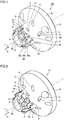
Fig. 1 is a schematic perspective view illustrating the structure of a cutting tool according to the present embodiment; -
Fig. 2 is a schematic perspective view illustrating the structure of a main body of the cutting tool according to the present embodiment; -
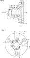
Fig. 3 is a schematic front view illustrating the structure of the main body of the cutting tool according to the present embodiment; -
Fig. 4 is a schematic side view illustrating the structure of the main body of the cutting tool according to the present embodiment; -
Fig. 5 is a schematic cross-sectional view taken along line V-V inFig. 3 ; -
Fig. 6 is a schematic cross-sectional view taken along line VI-VI inFig. 4 ; -
Fig. 7 is a schematic side view illustrating the structure of a cutter of the cutting tool according to the present embodiment; -
Fig. 8 is a schematic cross-sectional view illustrating a state in which the cutter is inserted in a hole of the main body; -
Fig. 9 is a schematic perspective view illustrating the structure of a cutting tool according to a modification of the present embodiment; -
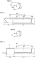
Fig. 10 is a schematic side view illustrating the structure of a cutter of the cutting tool according to a first modification of the present embodiment; -
Fig. 11 is a schematic front view illustrating the structure of a cutter of the cutting tool according to the first modification of the present embodiment; -
Fig. 12 is a schematic side view illustrating the structure of a cutter of the cutting tool according to a second modification of the present embodiment; -
Fig. 13 is a schematic front view illustrating the structure of a cutter of the cutting tool according to the second modification of the present embodiment; -
Fig. 14 is a schematic side view illustrating the structure of a cutter of the cutting tool according to a third modified example of the present embodiment; -
Fig. 15 is a schematic front view illustrating the structure of a cutter of the cutting tool according to the third modification of the present embodiment; -
Fig. 16 is an exploded schematic perspective view illustrating the structure of the cutting tool according to the present embodiment; and -
Fig. 17 is a schematic partial cross-sectional view illustrating the structure of the cutting device according to the present embodiment. - According to the valve finisher, a part of the outer periphery of the main body is cut off so as to form a pocket in the outer periphery, and each cutting insert is disposed in the pocket. Since the outer peripheral portion of the main body is cut off so as to form a pocket therein, the strength and the rigidity of the main body are reduced. Therefore, it is difficult to hold a large number of cutting inserts (cutter) in the main body. As a result, it is necessary to cut a workpiece with a small number of cutters, which consequently deteriorates the durability of cutting edges.
- An object of one aspect of the present disclosure is to provide a cutting tool and a cutting device capable of improving the durability of cutters.
- According to one aspect of the present disclosure, there is provided a cutting tool and a cutting device capable of improving the durability of cutters.
- First, aspects of the present disclosure will be described briefly hereinafter.
- (1) A
cutting tool 100 according to one aspect of the present disclosure includes amain body 10 and acutter 20. Themain body 10 has an outerperipheral surface 30 with oneend 16 and theother end 17. Thecutter 20 is fixed to themain body 10. Themain body 10 is provided with ahole 6 extending in a direction from aregion 15 surrounded by oneend 16 to aregion 18 surrounded by theother end 17. When viewed from the above direction, the shape of theopening 19 of thehole 6 is circular, and thehole 6 is provided inner than the outerperipheral surface 30. Thecutter 20 has a member disposed inside thehole 6.
After extensive researches for a solution to improve the durability of cutters, the inventors of the present disclosure have achieved the following findings, and thereby established one aspect of the present disclosure. In order to improve the durability of the cutter, it is effective to use a large number of cutters so as to reduce the load of each cutter. In order to use a large number of cutters, it is required to improve the strength of the main body. After extensive studies, the inventors have conceived the idea of providing the cutters inner than the outer peripheral surface of the main body other than on the outer periphery of the main body. As a result, compared with the case where the outer periphery of the main body is cut off to form a pocket, the volume to be cut off the main body is smaller, which makes it possible to improve the strength of the main body.
When a location for disposing the cutter is provided inner than the outer peripheral surface of the main body, it is required to machine the main body in the axial direction instead of in the radial direction. Normally, the shape of a shank for holding a cutting edge is rectangular in plan view. However, in order to form a rectangular hole in the main body along the axial direction in plan view, it is required to perform, for example, electric discharge machining. Compared with machining by a combination of drill machining and subsequent reamer finishing, the electric discharge machining is lower in machining accuracy and longer in machining time, and thereby it is difficult to form a rectangular hole in plan view. Therefore, in the present disclosure, drill machining and subsequent reamer finishing, for example, are used to form a hole having a circular opening in the main body in plan view.
According to thecutting tool 100 according to one aspect of the present disclosure, the shape of theopening 19 of thehole 6 provided in themain body 10 is circular, and thehole 6 is provided inner than the outerperipheral surface 30, which makes it possible to improve the strength of themain body 10. As a result, a large number ofcutters 20 can be attached to themain body 10, which makes it possible to improve the durability of eachcutter 20. - (2) In the
cutting tool 100 according to the above (1), thecutter 20 may include acutting edge 21 and ashank 22 configured to hold thecutting edge 21. Theshank 22 may be disposed inside thehole 6. Thecutting edge 21 may be exposed from thehole 6. Thereby, it is possible to improve the durability of thecutting edge 21. - (3) In the
cutting tool 100 according to the above (2), when viewed from the above direction, theshank 22 has afirst side face 24 which is linear and asecond side face 23 which is arc-shaped and provided contiguous to thefirst face 24. Since the arc-shaped second side face 23 contacts the inner peripheral surface of thehole 6, it is possible to improve the positioning accuracy of theshank 22 in the radial direction, which contributes to the improvement of the cutting accuracy. - (4) The
cutting tool 100 according to the above (3) may further include afastening member 41 configured to fix theshank 22 to themain body 10. Thefastening member 41 may be in contact with thefirst side face 24. As a result, it is possible to suppress the rotation of theshank 22, which makes it possible to firmly fix theshank 22 to themain body 10. - (5) The
cutting tool 100 according to the above (3) or (4) may further include aposition adjusting member 42 configured to adjust the position of thecutter 20 in the above direction. Theshank 22 may include a third side face 25 which is a flat surface inclined with respect to the above direction and provided contiguous to thefirst side face 24. Theposition adjusting member 42 may be in contact with thethird side face 25. Thereby, it is possible to adjust the position of thecutter 20 in the above direction with high accuracy, which contributes to the improvement of the cutting accuracy. - (6) In the
cutting tool 100 according to any one of the above (2) to (5), theshank 22 may have ahead portion 221 configured to hold thecutting edge 21 and aroot portion 222 opposite to thehead portion 221. When viewed from the above direction, theroot portion 222 may be completely surrounded by themain body 10. As a result, it is possible to suppress the inclination of theshank 22 with respect to the above direction. - (7) In the
cutting tool 100 according to any one of the above (2) to (6), thecutting edge 21 may contact themain body 10, which makes it possible to suppress the vibration of thecutting edge 21 during machining. - (8) The
cutting tool 100 according to any one of the above (1) to (7) may further include areamer 52 provided on the one end side. As a result, it is possible to machine the inner peripheral surface of the valve seat with thecutter 20 while performing finish machining of a hole in the stem guide with the reamer, for example. - (9) In the
cutting tool 100 according to any one of the above (1) to (8), thecutter 20 may include six or more cutter members separated from each other. As a result, the resistance to eachcutter 20 is reduced, which makes it possible to further improve the durability of thecutters 20. - (10) In the
cutting tool 100 according to any one of the above (1) to (9), thecutter 20 may include afirst cutter member 20a, asecond cutter member 20b and athird cutter member 20c. Thefirst cutter member 20a may include a firstcutting edge portion 21a having a first angle θ1, and afirst shank portion 22a configured to hold the firstcutting edge portion 21a. Thesecond cutter member 20b includes a secondcutting edge portion 21b having a second angle θ2 larger than the first angle θ1, and asecond shank portion 22b which is configured to hold the secondcutting edge portion 21b and is shorter than thefirst shank portion 22a. Thethird cutter member 20c includes a thirdcutting edge portion 21c having a third angle θ3 larger than the second angle θ2, and athird shank portion 22c which is configured to hold the thirdcutting edge portion 21c and is shorter than thesecond shank portion 22b. Thereby, it is possible to form an article having an inner peripheral surface whose angle changes along the above direction. - (11) In the
cutting tool 100 according to any one of the above (1) to (9), thecutter 20 may include afirst cutter member 20a, asecond cutter member 20b, and athird cutter member 20c. Thefirst cutter member 20a, thesecond cutter member 20b and thethird cutter member 20c may each have a correspondingcutting edge portion first portion 31 having a first angle θ1, asecond portion 32 having a second angle θ2 larger than the first angle θ1, and athird portion 33 having a third angle θ3 larger than the second angle θ2. Thereby, it is possible to form an article having an inner peripheral surface with different angles. - (12) A cutting device 200 according to one aspect of the present disclosure includes the
cutting tool 100 according to any one of the above (1) to (9) and a drivingunit 57 configured to rotate thecutting tool 100. Thereby, it is possible to provide the cutting device 200 capable of improving the durability of thecutter 20. - Hereinafter, an embodiment of the present disclosure will be described in detail with reference to the drawings. It should be noted that in the following drawings, the same or corresponding parts are denoted by the same reference numerals, and the description thereof will not be repeated.
- First, the structure of a
cutting tool 100 according to the present embodiment will be described. - As illustrated in
Fig. 1 , thecutting tool 100 according to the present embodiment mainly includes amain body 10, acutter 20, afastening member 41, and aposition adjusting member 42. Themain body 10 has, for example, a hollow cylindrical shape. Themain body 10 surrounds anaxis line 1. A space formed by an innerperipheral surface 9 of themain body 10 extends along theaxis line 1. Themain body 10 is provided with arecess 2 and a hole 6 (seeFig. 5 ) in communication with therecess 2. Thecutter 20 is disposed inside the hole 6 (seeFig. 8 ). Thecutter 20 includes acutting edge 21 and ashank 22 configured to hold thecutting edge 21. Theshank 22 is disposed inside thehole 6. At least a part of thecutting edge 21 is positioned in therecess 2. - As illustrated in
Fig. 2 , themain body 10 has an outerperipheral surface 30. The outerperipheral surface 30 has oneend 16 and the other end 17 (seeFig. 4 ). The hole 6 (seeFig. 5 ) extends in a first direction A from oneregion 15 surrounded by oneend 16 to theother region 18 surrounded by theother end 17. The first direction A is, for example, a direction parallel to theaxis line 1. Specifically, thehole 6 extends, for example, along the direction parallel to theaxis line 1. As illustrated inFig. 2 , therecess 2 opens to the side of oneend 16 and the outerperipheral surface 30. A plurality ofrecesses 2 are provided along the circumferential direction of theaxis line 1. The number of theholes 6 and therecesses 2 is, for example, 6, but it is not particularly limited thereto. Preferably, the number of theholes 6 and therecesses 2 is 6 or more. - As illustrated in
Fig. 3 , when viewed from the first direction A, the shape of theopening 19 of thehole 6 is circular. Preferably, when viewed from the first direction A, the inner sectional shape of thehole 6 is also circular. When viewed from the first direction A, thehole 6 may be provided inner than oneend 16 or may be provided inner than theother end 17. Thehole 6 is provided inner than the outerperipheral surface 30. When viewed from the first direction A, thehole 6 is provided outer than the innerperipheral surface 9. Thehole 6 is, for example, a blind hole. - As illustrated in
Fig. 3 , a plurality ofholes 6 are provided in themain body 10 along the circumferential direction of theaxis line 1. When viewed from the direction parallel to theaxis line 1, the plurality ofholes 6 are provided on the same circle centered on theaxis line 1. In other words, when viewed from the direction parallel to theaxis line 1, the distance from the center of each of the plurality ofholes 6 to theaxis line 1 is identical. The number of theholes 6 is for example 6, but it is not limited to 6. Preferably, the number ofholes 6 is 6 or more. The number of theholes 6 is the same as the number of therecesses 2. Themain body 10 is provided with a plurality of throughholes 5. When viewed from the direction parallel to theaxis line 1, the plurality of throughholes 5 are provided on the same circle centered on theaxis line 1. The throughholes 5 extend in the direction parallel to theaxis line 1. The number of the throughholes 5 is, for example, 3, but it is not limited to 3. - As illustrated in
Fig. 4 , themain body 10 includes a firstmain body region 11, a secondmain body region 12, a thirdmain body region 13, and a fourthmain body region 14. The firstmain body region 11 has oneend 16. The width W1 of the firstmain body region 11 may increase gradually in the first direction A. The secondmain body region 12 is provided contiguous to the firstmain body region 11. The width W2 of the firstmain body region 11 is constant in the first direction A. Therecess 2 extends so as to cross the boundary between the firstmain body region 11 and the secondmain body region 12.Holes 3 are provided in the secondmain body region 12. - The third
main body region 13 is provided contiguous to the secondmain body region 12. The width of the thirdmain body region 13 increases monotonically in the firstdirection A. Holes 4 and throughholes 5 are provided in the thirdmain body region 13. The fourthmain body region 14 is provided contiguous to the thirdmain body region 13. The width W3 of the fourthmain body region 14 is constant in the first direction A. As illustrated inFig. 4 , in a second direction B (that is, the radial direction B) perpendicular to theaxis line 1, the width W3 of the fourthmain body region 14 is larger than the width W2 of the secondmain body region 12. In the radial direction B, the width W1 of oneregion 15 surrounded by oneend 16 is smaller than the width of theother region 18 surrounded by theother end 17. - As illustrated in
Fig. 4 , when viewed from the radial direction, themain body 10 has aprojection member 35 that covers a part of therecess 2. Theprojection member 35 projects from the opening end of theconcave portion 2 along the circumferential direction of themain body 10. As illustrated inFig. 1 , thecutting edge 21 may be in contact with theprojection member 35 of themain body 10, which makes it possible to suppress the vibration of thecutting edge 21. - As illustrated in
Fig. 5 , the diameter of thehole 6 may be constant in the first direction A. Thehole 3 may communicate with thehole 6. Thehole 4 may communicate with thehole 6. Ahole 7 may be provided in therecess 2. Thehole 7 may penetrate therecess 2 and the innerperipheral surface 9. Ahole 8 may be provided in theother region 18 surrounded by theother end 17. Thehole 8 is configured to align themain body 10 with aconnection member 50. As illustrated inFig. 6 , the cross-sectional shape of thehole 6 may be circular. Each of the plurality ofholes 6 may be provided on the same cross section. The cross-sectional shape of the innerperipheral surface 9 may be circular. - As illustrated in
Fig. 1 , thecutter 20 may include a plurality ofcutter members peripheral surface 30 along the circumferential direction thereof. The number of cutter members is not particularly limited. The number of cutter members is preferably 6 or more, and more preferably 9 or more. When the number of cutter members is 6, thecutter 20 includes the first cutter member to the sixth cutter member. Each of the first to sixth cutter members has a corresponding cutting edge portion. Each of the first to sixth cutter members is arranged inside acorresponding hole 6. It is not necessary to arrange a cutter member in each of theholes 6. In other words, the number of cutter members may be smaller than the number ofholes 6. - As illustrated in
Fig. 7 , thecutter 20 includes thecutting edge 21 and theshank 22. Theshank 22 holds thecutting edge 21. Theshank 22 has afirst side face 24, asecond side face 23, and athird side face 25. Thefirst side face 24 and thethird side face 25 are flat. Thesecond side face 23 is curved. Thesecond side face 23 is provided contiguous to thefirst side face 24. Thethird side face 25 is provided contiguous to thefirst side face 24. When viewed from the first direction A, thefirst side face 24 is linear. When viewed from the first direction A, thesecond side face 23 is arc-shaped. Thethird side face 25 is inclined with respect to thefirst side face 24. - As illustrated in
Fig. 7 , thecutting edge 21 has afirst section 31 having a first angle θ1, asecond section 32 having a second angle θ2, and athird section 33 having a third angle θ3. The second angle θ2 may be larger than the first angle θ1. The third angle θ3 may be larger than the second angle θ2. The first angle θ1 is, for example, 20°. The second angle θ2 is, for example, 45°. The third angle θ3 is, for example, 90°. Thefirst section 31 is contiguous to thesecond section 32. Thesecond section 32 is contiguous to thethird section 33. Thefirst section 31 and thethird section 33 are joined together by thesecond section 32. -
Fig. 8 illustrates a state in which theshank 22 is inserted into thehole 6. As illustrated inFig. 8 , theshank 22 is disposed in thehole 6. In other words, theshank 22 is completely disposed inside thehole 6. A part of theshank 22 may be exposed from thehole 6. Thecutting edge 21 is exposed from thehole 6. - The
fastening member 41 is configured to fix theshank 22 to themain body 10. As illustrated inFig. 8 , thefastening member 41 is disposed inside thehole 3 in communication with thehole 6. Thefastening member 41 is, for example, a bolt. Thefastening member 41 is configured to contact the planarfirst side face 24. When thefastening member 41 presses thefirst side face 24, thesecond side face 23 opposite to thefirst side face 24 is pressed against themain body 10. Thereby, theshank 22 is fixed to themain body 10. Thefirst side face 24 may be separated from themain body 10. - The
position adjusting member 42 is configured to adjust the position of thecutter 20 in the first direction A. As illustrated inFig. 8 , theposition adjusting member 42 is provided in thehole 4 communicating with thehole 6. Theposition adjusting member 42 is, for example, a bolt. The third side face 25 included in theshank 22 is a flat surface inclined with respect to the first direction A, and is provided contiguous to thefirst side face 24. Thethird side face 25 is inclined, for example, by 45° with respect to thefirst side face 24. Theposition adjusting member 42 is configured to contact thethird side face 25. In the first direction A, thehole 4 is provided between thehole 3 and the other end 17 (seeFig. 4 ). - By adjusting the height of the
position adjusting member 42 in the direction along which thehole 4 extends (i.e., the vertical direction inFig. 8 ), the position where theposition adjusting member 42 contacts thethird side face 25 is changed. Specifically, when theposition adjusting member 42 is adjusted to move downward, theshank 22 is moved to the left side (the direction approaching one end). Conversely, when theposition adjusting member 42 is adjusted to move upward, theshank 22 is moved to the right side (the direction approaching the other end). As illustrated inFig. 8 , theshank 22 may have ahead portion 221 configured to hold thecutting edge 21, and aroot portion 222 opposite to thehead portion 221. When viewed from the first direction A, theroot portion 222 may be completely surrounded by themain body 10. - Each of the plurality of
cutter members Fig. 9 , thecutter 20 includes afirst cutter member 20a, asecond cutter member 20b, and athird cutter member 20c. As illustrated inFigs. 10 and11 , thefirst cutter member 20a may have a firstcutting edge portion 21a having a first angle θ1 and afirst shank portion 22a configured to hold the firstcutting edge portion 21a. The first angle θ1 is, for example, 20°. Thefirst shank portion 22a has a planarfirst side face 24a and a curvedsecond side face 23a. Thesecond side face 23a is provided contiguous to thefirst side face 24a. When viewed from the first direction A, thesecond side face 23a is arc-shaped. - As illustrated in
Figs. 12 and 13 , thesecond cutter member 20b may have a secondcutting edge portion 21b having a second angle θ2 and asecond shank portion 22b configured to the secondcutting edge portion 21b. The second angle θ2 is larger than the first angle θ1. The second angle θ2 is, for example, 45°. The length L12 of thesecond shank portion 22b in the first direction A may be shorter than the length L11 of thefirst shank portion 22a. The length L22 of the secondcutting edge portion 21b in the first direction A may be shorter than the length L21 of the firstcutting edge portion 21a. Thesecond shank portion 22b has a planarfirst side face 24b and a curvedsecond side face 23b. Thesecond side face 23b is provided contiguous to thefirst side face 24b. When viewed from the first direction A, thesecond side face 23b is arc-shaped. - As illustrated in
Figs. 14 and15 , thethird cutter member 20c may have a thirdcutting edge portion 21c having a third angle θ3 and athird shank portion 22c configured to hold the thirdcutting edge portion 21c. The third angle θ3 is larger than the second angle θ2. The third angle θ3 is, for example, 90°. The length L13 of thethird shank portion 22c in the first direction A may be shorter than the length L12 of thesecond shank portion 22b. The length L23 of the thirdcutting edge portion 21c may be shorter than the length L22 of the secondcutting edge portion 21b. Thethird shank portion 22c has a planarfirst side face 24c and a curvedsecond side face 23c. Thesecond side face 23c is provided contiguous to thefirst side face 24c. When viewed from the first direction A, thesecond side face 23c is arc-shaped. - As illustrated in
Fig. 16 , thecutting tool 100 may further include aconnection member 50, areamer holding member 55, and ascrew 51. Themain body 10 is provided with aprotrusion 59 for positioning. Theprotrusion 59 is engaged into thehole 8 provided in themain body 10. Themain body 10 is fixed to theconnection member 50 by using thescrew 51. Thescrew 51 passes through the throughhole 5 provided in themain body 10 and is fastened in ascrew hole 56 provided in theconnection member 50. Thereby, themain body 10 is fixed to theconnection member 50. Thereamer holding member 55 is configured to penetrate the space surrounded by the innerperipheral surface 9 of themain body 10. As described in the above, themain body 10 is configured to be detachable from theconnection member 50. As illustrated inFig. 17 , areamer 52 is provided on oneend 16 side of themain body 10. Thereamer 52 is held by thereamer holding member 55. Thereamer 52 extends in the same direction as theaxis line 1. - Hereinafter, the structure of the cutting device 200 according to the present embodiment will be described.
- As illustrated in
Fig. 17 , the cutting device 200 mainly includes thecutting tool 100 described in the above and a drivingunit 57. Thecutting tool 100 mainly includes amain body 10, acutter 20, aconnection member 50, areamer 52, and areamer holding member 55. Themain body 10 is configured to be rotatable around theaxis line 1. The drivingunit 57 is, for example, a main shaft of an equipment. As the drivingunit 57 rotates, theconnection member 50 and themain body 10 are driven to rotate. In other words, the rotational force is transmitted from the drivingunit 57 to theconnection member 50. - As the
main body 10 rotates, the plurality ofcutters 20 provided along the circumferential direction of themain body 10 are driven to rotate around theaxis line 1. As a result, the inner peripheral surface of thevalve seat 53 is machined by thecutting edge 21 of eachcutter 20. Similarly, as thereamer 52 held by thereamer holding member 55 is driven to rotate, a hole is machined in thestem guide 58 provided in thecylinder head 54. Since thereamer 52 and themain body 10 are driven to rotate about thesame axis line 1, the inner peripheral surface of thevalve seat 53 and the hole of thestem guide 58 are machined simultaneously. - Hereinafter, the functions and effects of the cutting tool and the cutting device according to the present embodiment will be described.
- According to the
cutting tool 100 of the present embodiment, when viewed from the first direction A, the shape of theopening 19 of thehole 6 provided in themain body 10 is circular, and thehole 6 is provided inner than the outerperipheral surface 30, which makes it possible to improve the strength of themain body 10. As a result, a large number ofcutters 20 can be attached to themain body 10, which makes it possible to improve the durability of eachcutter 20. - According to the
cutting tool 100 of the present embodiment, thecutter 20 includes thecutting edge 21 and theshank 22 configured to hold thecutting edge 21. Theshank 22 is disposed inside thehole 6. Thecutting edge 21 is exposed from thehole 6. Thereby, it is possible to improve the durability of thecutting edge 21. - Moreover, according to the
cutting tool 100 of the present embodiment, when viewed from the first direction A, theshank 22 has afirst side face 24 which is linear, and asecond side face 23 which is arc-shaped and provided contiguous to thefirst face 24. Since the arc-shaped second side face 23 contacts the inner peripheral surface of thehole 6, it is possible to improve the positioning accuracy of theshank 22 in the radial direction, which contributes to the improvement of the cutting accuracy. - Moreover, according to the
cutting tool 100 of the present embodiment, there is further provided afastening member 41 configured to fix theshank 22 to themain body 10. Thefastening member 41 is in contact with thefirst side face 24. As a result, it is possible to suppress the rotation of theshank 22, which makes it possible to firmly fix theshank 22 to themain body 10. - Moreover, according to the
cutting tool 100 of the present embodiment, there is further provided aposition adjusting member 42 configured to adjust the position of thecutter 20 in the first direction A. Theshank 22 includes a third side face 25 which is a flat surface inclined with respect to the above direction and provided contiguous to thefirst side face 24. Theposition adjusting member 42 is in contact with thethird side face 25. Thereby, it is possible to adjust the position of thecutter 20 in the above direction with high accuracy, which contributes to the improvement of the cutting accuracy. - Moreover, according to the
cutting tool 100 of the present embodiment, theshank 22 has ahead portion 221 configured to hold thecutting edge 21 and aroot portion 222 opposite to thehead portion 221. When viewed from the first direction A, theroot portion 222 is completely surrounded by themain body 10. As a result, it is possible to suppress the inclination of theshank 22 with respect to the first direction A. - Moreover, according to the
cutting tool 100 of the present embodiment, thecutting edge 21 contacts themain body 10, which makes it possible to suppress the vibration of thecutting edge 21 during machining. - Moreover, according to the
cutting tool 100 of the present embodiment, there is further provided areamer 52 on one end side. As a result, it is possible to machine the inner peripheral surface of the valve seat with thecutter 20 while performing finish machining of a hole in the stem guide with the reamer, for example. - Furthermore, according to the
cutting tool 100 of the present embodiment, thecutter 20 includes six or more cutter members separated from each other. As a result, the resistance to eachcutter 20 is reduced, , which makes it possible to further improve the durability of thecutters 20. - Moreover, according to the
cutting tool 100 of the present embodiment, thecutter 20 includes afirst cutter member 20a, asecond cutter member 20b, and athird cutter member 20c. Thefirst cutter member 20a includes a firstcutting edge portion 21a having a first angle θ1, and afirst shank portion 22a configured to hold the firstcutting edge portion 21a. Thesecond cutter member 20b includes a secondcutting edge portion 21b having a second angle θ2 larger than the first angle θ1, and asecond shank portion 22b which is configured to hold the secondcutting edge portion 21b and is shorter than thefirst shank portion 22a. Thethird cutter member 20c includes a thirdcutting edge portion 21c having a third angle θ3 larger than the second angle θ2, and athird shank portion 22c which is configured to hold the thirdcutting edge portion 21c and is shorter than thesecond shank portion 22b. Thereby, it is possible to form an article having an inner peripheral surface whose angle changes along the first direction A. - Furthermore, according to the
cutting tool 100 of the present embodiment, thecutter 20 includes afirst cutter member 20a, asecond cutter member 20b, and athird cutter member 20c. Thefirst cutter member 20a, thesecond cutter member 20b and thethird cutter member 20c each has a correspondingcutting edge portion first portion 31 having a first angle θ1, asecond portion 32 having a second angle θ2 larger than the first angle θ1, and athird portion 33 having a third angle θ3 larger than the second angle θ2. Thereby, it is possible to form an article having an inner peripheral surface with different angles. - The cutting device 200 according to the present embodiment includes the
cutting tool 100 and a drivingunit 57 configured to rotate thecutting tool 100. Thereby, it is possible to provide the cutting device 200 capable of improving the durability of thecutter 20. - It should be understood that the embodiments disclosed herein have been presented for the purpose of illustration and description but not limited in all aspects. It is intended that the scope of the present disclosure is not limited to the description above but defined by the scope of the claims and encompasses all modifications equivalent in meaning and scope to the claims.
- 1: axis line; 2: recess; 3, 4, 6, 7, 8: hole; 5: through hole; 9: inner peripheral surface; 10: main body; 11: first main body region; 12: second main body region; 13: third main body region; 14: fourth main body region; 15: one region; 16: one end; 17: the other end; 18: the other region; 19: opening; 20: cutter; 20a: first cutter member; 20b: second cutter member; 20c: third cutter member; 21: cutting edge; 21a: first cutting edge portion; 21b: second cutting edge portion; 21c: third cutting edge portion; 22: shank; 22a: first shank portion; 22b: second shank portion; 22c: third shank portion; 23, 23a, 23b, 23c: second side face; 24, 24a, 24b, 24c: first side face; 25: third side face; 30: outer peripheral surface; 31: first section; 32: second section; 33: third section; 35: projection member; 41: fastening member, 42: position adjusting member; 50: connection member; 51: screw; 52: reamer; 53: valve seat; 54: cylinder head; 55: reamer holding member; 56: screw hole; 57: driving unit; 58: stem guide; 59: protrusion; 100: cutting tool; 200: cutting device; 221: head portion; 222: root portion; A: first direction; B: second direction (radial direction); L11, L12, L13, L21, L22, L23: length; W1, W2, W3: width.
Claims (12)
- A cutting tool comprising:a main body having an outer peripheral surface with one end and the other end; anda cutter fixed to the main body,the main body being provided with a hole extending in a direction from a region surrounded by the one end toward a region surrounded by the other end,when viewed from the above direction, the shape of the opening of the hole is circular, the hole being provided inner than the outer peripheral surface,the cutter having a member disposed inside the hole.
- The cutting tool according to claim 1, wherein
the cutter includes a cutting edge, and a shank configured to hold the cutting edge,
the shank is disposed inside the hole,
the cutting edge is exposed from the hole. - The cutting tool according to claim 2, wherein
when viewed from the above direction, the shank includes a first side face which is linear and a second side face which is arc-shaped and provided contiguous to the first side face. - The cutting tool according to claim 3, further comprising a fastening member configured to fix the shank to the main body, wherein
the fastening member is in contact with the first side face. - The cutting tool according to claim 3 or 4, further comprising a position adjusting member configured to adjust the position of the cutter in the above direction, wherein
the shank includes a third side face which is a flat surface inclined with respect to the above direction and provided contiguous to the first side face,
the position adjusting member is in contact with the third side face. - The cutting tool according to any one of claims 2 to 5, wherein
the shank has a head portion configured to hold the cutting edge and a root portion opposite to the head portion,
when viewed from the above direction, the root portion is completely surrounded by the main body. - The cutting tool according to any one of claims 2 to 6, wherein
the cutting edge contacts the main body. - The cutting tool according to any one of claims 1 to 7, further comprising a reamer provided on the one end side.
- The cutting tool according to any one of claims 1 to 8, wherein
the cutter includes six or more cutter members separated from each other. - The cutting tool according to any one of claims 1 to 9, wherein
the cutter includes a first cutter member, a second cutter member and a third cutter member,
the first cutter member includes a first cutting edge portion having a first angle, and a first shank portion configured to hold the first cutting edge portion,
the second cutter member includes a second cutting edge portion having a second angle larger than the first angle, and a second shank portion which is configured to hold the second cutting edge portion and is shorter than the first shank portion,
the third cutter member includes a third cutting edge portion having a third angle larger than the second angle, and a third shank portion which is configured to hold the third cutting edge portion and is shorter than the second shank portion. - The cutting tool according to any one of claims 1 to 9, wherein
the cutter includes a first cutter member, a second cutter member and a third cutter member,
each of the first cutter member, the second cutter member and the third cutter member has a corresponding cutting edge portion,
each cutting edge portion includes a first portion having a first angle, a second portion having a second angle larger than the first angle, and a third portion having a third angle larger than the second angle. - A cutting device comprising:a cutting tool according to any one of claims 1 to 11, anda driving unit configured to rotate the cutting tool.
Applications Claiming Priority (2)
| Application Number | Priority Date | Filing Date | Title |
|---|---|---|---|
| JP2015224035A JP6769009B2 (en) | 2015-11-16 | 2015-11-16 | Cutting tools and cutting equipment |
| PCT/JP2016/080317 WO2017086066A1 (en) | 2015-11-16 | 2016-10-13 | Cutting tool and cutting device |
Publications (3)
| Publication Number | Publication Date |
|---|---|
| EP3378588A1 true EP3378588A1 (en) | 2018-09-26 |
| EP3378588A4 EP3378588A4 (en) | 2019-06-19 |
| EP3378588B1 EP3378588B1 (en) | 2024-12-25 |
Family
ID=58718710
Family Applications (1)
| Application Number | Title | Priority Date | Filing Date |
|---|---|---|---|
| EP16866068.6A Active EP3378588B1 (en) | 2015-11-16 | 2016-10-13 | Cutting tool and cutting device |
Country Status (7)
| Country | Link |
|---|---|
| US (1) | US20190061018A1 (en) |
| EP (1) | EP3378588B1 (en) |
| JP (1) | JP6769009B2 (en) |
| KR (1) | KR20180081045A (en) |
| CN (1) | CN108136513B (en) |
| MX (1) | MX2018004197A (en) |
| WO (1) | WO2017086066A1 (en) |
Families Citing this family (3)
| Publication number | Priority date | Publication date | Assignee | Title |
|---|---|---|---|---|
| CN109175532A (en) * | 2018-11-08 | 2019-01-11 | 广西玉柴机器股份有限公司 | A kind of processing cylinder head valve retainer sealing surface cutter |
| US20210394283A1 (en) * | 2020-06-18 | 2021-12-23 | David Giles | Spherical cutting tool, system and method of using |
| US20220371110A1 (en) * | 2020-10-29 | 2022-11-24 | Sumitomo Electric Hardmetal Corp. | Cutting tool |
Family Cites Families (42)
| Publication number | Priority date | Publication date | Assignee | Title |
|---|---|---|---|---|
| US1495910A (en) * | 1921-09-26 | 1924-05-27 | George A Lefort | Tool for reseating and resurfacing valves and the like |
| US1453643A (en) * | 1922-01-10 | 1923-05-01 | Harry T Shearer | Reaming tool for truing valve seats |
| US1846890A (en) * | 1930-02-12 | 1932-02-23 | Harry G Miller | Valve reseating tool |
| US2102707A (en) * | 1936-09-16 | 1937-12-21 | H & H Machine & Motor Parts Co | Valve-seat surfacing tool |
| US2586955A (en) * | 1950-04-12 | 1952-02-26 | Ingersoll Milling Machine Co | Finishing cutter |
| US2751663A (en) * | 1951-05-25 | 1956-06-26 | Stahag Steel & Hard Metal Imp | Facing head, particularly for the milling of steel, bronze and cast iron |
| GB1160425A (en) * | 1966-07-20 | 1969-08-06 | Marsh Brothers & Co Ltd | Improvements in or relating to Cutting Tools. |
| US4353670A (en) * | 1980-06-02 | 1982-10-12 | Everede Tool Company | Machining tool |
| DE3801394A1 (en) * | 1988-01-19 | 1989-07-27 | Zerspannungstech Gmbh & Co Kg | KNIFE HEAD |
| US5044841A (en) * | 1990-07-20 | 1991-09-03 | Litton Industrial Automation Systems, Inc. | Valve seat bushing machining apparatus |
| DE4214343A1 (en) * | 1992-05-05 | 1993-11-11 | Fischer Artur Werke Gmbh | Device for producing boreholes with an undercut |
| JP3154648B2 (en) * | 1995-08-22 | 2001-04-09 | 本田技研工業株式会社 | Rotary cutting tool |
| US5704741A (en) * | 1995-12-27 | 1998-01-06 | Master Tool Corporation | Valve seat tool |
| DE29606578U1 (en) * | 1996-04-11 | 1996-06-20 | Jongen, Werkzeugtechnik GmbH, 47877 Willich | Milling tool |
| DE19648039A1 (en) * | 1996-11-20 | 1998-02-26 | Bayerische Motoren Werke Ag | Cutting tool holder for face milling |
| US5876155A (en) * | 1997-05-15 | 1999-03-02 | Ford Global Technologies, Inc. | Method of eliminating chatter in plunge cutting with cutters at different diameters and depths |
| IL120948A0 (en) * | 1997-05-29 | 1997-09-30 | Iscar Ltd | Cutting tool assembly |
| DE19800440A1 (en) * | 1998-01-08 | 1999-07-15 | Maier Kg Andreas | Cutter head with one- to three-dimensionally adjustable cutting insert and with a form-fitting cutting insert |
| JP2000126920A (en) * | 1998-10-22 | 2000-05-09 | Sumitomo Electric Ind Ltd | Face milling cutter |
| JP2001071204A (en) * | 1999-09-03 | 2001-03-21 | Mitsubishi Materials Corp | Inserts, holders and cutting tools |
| JP2002331412A (en) * | 2001-05-09 | 2002-11-19 | Mitsubishi Materials Corp | Face milling |
| DE10144923A1 (en) * | 2001-09-12 | 2003-03-27 | Guehring Joerg | Cutting tool with indexable insert |
| JP4017377B2 (en) * | 2001-10-25 | 2007-12-05 | 栄 清水 | Cutting tools |
| SE0103752L (en) * | 2001-11-13 | 2003-05-14 | Sandvik Ab | Rotatable tool for chip separating machining and cutting part herewith |
| US6739807B2 (en) * | 2001-11-26 | 2004-05-25 | Valenite Llc | Rotatable cutting tool |
| JP4248978B2 (en) * | 2002-10-03 | 2009-04-02 | 三菱マテリアル株式会社 | Drilling tool |
| SE0301456D0 (en) * | 2003-05-20 | 2003-05-20 | Sandvik Ab | An edge-bearing drill body, and a method of manufacturing and drilling tool comprising such drill body |
| JP4498704B2 (en) * | 2003-09-01 | 2010-07-07 | 三菱マテリアル株式会社 | Drilling tool |
| JP4212991B2 (en) * | 2003-09-01 | 2009-01-21 | 三菱マテリアル株式会社 | Drilling tool |
| SE528020C2 (en) * | 2004-01-14 | 2006-08-08 | Sandvik Intellectual Property | Rotatable chip separating tool |
| US20070020052A1 (en) * | 2005-07-25 | 2007-01-25 | Master Tool Corporation | Robust vavle seat tool and associated provision method |
| JP4500748B2 (en) * | 2005-09-02 | 2010-07-14 | 住友電工ハードメタル株式会社 | Throw-away tool |
| DE102006005379B4 (en) * | 2006-02-03 | 2015-02-12 | Kennametal Inc. | Combination tool and method of machining a borehole and its bore surface |
| DE102007019933A1 (en) * | 2007-04-27 | 2008-10-30 | Kennametal Inc. | Blade holder with soldered cutting body and milling cutter head |
| DE202007011816U1 (en) * | 2007-08-24 | 2007-12-20 | Jakob Lach Gmbh & Co. Kg | Monoblock milling cutter |
| CA2712796A1 (en) * | 2009-08-06 | 2011-02-06 | Textron Innovations Inc. | Hole saw with tapered pilot bit |
| JP5433344B2 (en) * | 2009-08-10 | 2014-03-05 | 東芝機械株式会社 | Composite tool, machine tool and machining method |
| JP2013071214A (en) * | 2011-09-28 | 2013-04-22 | Kyocera Corp | Cutting tool |
| DE102011117148B4 (en) * | 2011-10-28 | 2022-05-05 | Kennametal Inc. | Rotary tool and method for producing a rotary tool and a cutting insert |
| DE102012209312A1 (en) * | 2012-06-01 | 2013-12-05 | Gühring Ohg | Modular tool holder |
| JP5725111B2 (en) * | 2013-09-13 | 2015-05-27 | 三菱マテリアル株式会社 | Cutting tools |
| US20170151614A1 (en) * | 2015-06-19 | 2017-06-01 | EIP Holdings, LLC | Adjustable face mill and method of manufacture |
-
2015
- 2015-11-16 JP JP2015224035A patent/JP6769009B2/en active Active
-
2016
- 2016-10-13 WO PCT/JP2016/080317 patent/WO2017086066A1/en not_active Ceased
- 2016-10-13 EP EP16866068.6A patent/EP3378588B1/en active Active
- 2016-10-13 MX MX2018004197A patent/MX2018004197A/en unknown
- 2016-10-13 KR KR1020187009879A patent/KR20180081045A/en not_active Withdrawn
- 2016-10-13 CN CN201680060078.XA patent/CN108136513B/en active Active
- 2016-10-13 US US15/767,275 patent/US20190061018A1/en not_active Abandoned
Also Published As
| Publication number | Publication date |
|---|---|
| EP3378588B1 (en) | 2024-12-25 |
| EP3378588A4 (en) | 2019-06-19 |
| CN108136513A (en) | 2018-06-08 |
| KR20180081045A (en) | 2018-07-13 |
| CN108136513B (en) | 2020-03-13 |
| JP6769009B2 (en) | 2020-10-14 |
| WO2017086066A1 (en) | 2017-05-26 |
| JP2017087391A (en) | 2017-05-25 |
| MX2018004197A (en) | 2018-05-17 |
| US20190061018A1 (en) | 2019-02-28 |
Similar Documents
| Publication | Publication Date | Title |
|---|---|---|
| EP2682212B1 (en) | Guide pad and cutting tool | |
| EP3094438B1 (en) | Indexable central drill insert and cutting tool therewith | |
| EP2764939A1 (en) | Cutting tool with replaceable blade edge | |
| EP3378588B1 (en) | Cutting tool and cutting device | |
| US20210086270A1 (en) | Cutting insert and cutting tool | |
| US10569375B2 (en) | Chip suction cover and machine tool | |
| CZ2005264A3 (en) | Tool for cutting operation | |
| CN104339028A (en) | Tool for the turning/turn broaching of workpieces | |
| KR101222291B1 (en) | Drill tool | |
| IL210500A (en) | Rotating cutting tool with support element | |
| KR20160099553A (en) | Rotary cutting tool having a disk-shaped cutter body provided with support pads | |
| US20160368063A1 (en) | Boring tool and boring method using same | |
| EP3533546B1 (en) | Tool with cutting insert | |
| EP3401046B1 (en) | Rotary cutting tool | |
| EP2398619B1 (en) | Reaming tool with a guide arrangement | |
| JP2009262307A (en) | Boring tool | |
| CN109843491B (en) | Cutting Tools, Insert Holders, and Inserts | |
| EP4306245A1 (en) | Cutting insert and cutting tool equipped with cutting insert | |
| EP2869956B1 (en) | Beveling tool for metal | |
| US20240100604A1 (en) | Cutting insert, holder, and blade-tip-replaceable cutting tool | |
| JP2007260788A (en) | Cutting insert and cutting tool | |
| JP5845816B2 (en) | Tip replacement type cutting tool | |
| JP2009184036A (en) | Cutting tools | |
| KR102901534B1 (en) | Milling cutter with wiper insert and interchangeable blade tip | |
| JP2016010837A (en) | Boring tool |
Legal Events
| Date | Code | Title | Description |
|---|---|---|---|
| STAA | Information on the status of an ep patent application or granted ep patent |
Free format text: STATUS: THE INTERNATIONAL PUBLICATION HAS BEEN MADE |
|
| PUAI | Public reference made under article 153(3) epc to a published international application that has entered the european phase |
Free format text: ORIGINAL CODE: 0009012 |
|
| STAA | Information on the status of an ep patent application or granted ep patent |
Free format text: STATUS: REQUEST FOR EXAMINATION WAS MADE |
|
| 17P | Request for examination filed |
Effective date: 20180409 |
|
| AK | Designated contracting states |
Kind code of ref document: A1 Designated state(s): AL AT BE BG CH CY CZ DE DK EE ES FI FR GB GR HR HU IE IS IT LI LT LU LV MC MK MT NL NO PL PT RO RS SE SI SK SM TR |
|
| AX | Request for extension of the european patent |
Extension state: BA ME |
|
| DAV | Request for validation of the european patent (deleted) | ||
| DAX | Request for extension of the european patent (deleted) | ||
| A4 | Supplementary search report drawn up and despatched |
Effective date: 20190516 |
|
| RIC1 | Information provided on ipc code assigned before grant |
Ipc: B23B 51/10 20060101AFI20190510BHEP Ipc: B23C 3/05 20060101ALI20190510BHEP Ipc: B23B 51/08 20060101ALN20190510BHEP Ipc: B23D 77/00 20060101ALN20190510BHEP |
|
| STAA | Information on the status of an ep patent application or granted ep patent |
Free format text: STATUS: EXAMINATION IS IN PROGRESS |
|
| 17Q | First examination report despatched |
Effective date: 20220128 |
|
| REG | Reference to a national code |
Ref country code: DE Ref legal event code: R079 Free format text: PREVIOUS MAIN CLASS: B23B0041120000 Ipc: B23B0051100000 Ref country code: DE Ref legal event code: R079 Ref document number: 602016090758 Country of ref document: DE Free format text: PREVIOUS MAIN CLASS: B23B0041120000 Ipc: B23B0051100000 |
|
| RIC1 | Information provided on ipc code assigned before grant |
Ipc: B23D 77/00 20060101ALN20240530BHEP Ipc: B23B 51/08 20060101ALN20240530BHEP Ipc: B23C 3/05 20060101ALI20240530BHEP Ipc: B23B 51/10 20060101AFI20240530BHEP |
|
| RIC1 | Information provided on ipc code assigned before grant |
Ipc: B23D 77/00 20060101ALN20240606BHEP Ipc: B23B 51/08 20060101ALN20240606BHEP Ipc: B23C 3/05 20060101ALI20240606BHEP Ipc: B23B 51/10 20060101AFI20240606BHEP |
|
| GRAP | Despatch of communication of intention to grant a patent |
Free format text: ORIGINAL CODE: EPIDOSNIGR1 |
|
| STAA | Information on the status of an ep patent application or granted ep patent |
Free format text: STATUS: GRANT OF PATENT IS INTENDED |
|
| RIC1 | Information provided on ipc code assigned before grant |
Ipc: B23D 77/00 20060101ALN20240625BHEP Ipc: B23B 51/08 20060101ALN20240625BHEP Ipc: B23C 3/05 20060101ALI20240625BHEP Ipc: B23B 51/10 20060101AFI20240625BHEP |
|
| RIC1 | Information provided on ipc code assigned before grant |
Ipc: B23D 77/00 20060101ALN20240708BHEP Ipc: B23B 51/08 20060101ALN20240708BHEP Ipc: B23C 3/05 20060101ALI20240708BHEP Ipc: B23B 51/10 20060101AFI20240708BHEP |
|
| INTG | Intention to grant announced |
Effective date: 20240731 |
|
| GRAS | Grant fee paid |
Free format text: ORIGINAL CODE: EPIDOSNIGR3 |
|
| GRAA | (expected) grant |
Free format text: ORIGINAL CODE: 0009210 |
|
| STAA | Information on the status of an ep patent application or granted ep patent |
Free format text: STATUS: THE PATENT HAS BEEN GRANTED |
|
| P01 | Opt-out of the competence of the unified patent court (upc) registered |
Free format text: CASE NUMBER: APP_60442/2024 Effective date: 20241108 |
|
| AK | Designated contracting states |
Kind code of ref document: B1 Designated state(s): AL AT BE BG CH CY CZ DE DK EE ES FI FR GB GR HR HU IE IS IT LI LT LU LV MC MK MT NL NO PL PT RO RS SE SI SK SM TR |
|
| REG | Reference to a national code |
Ref country code: GB Ref legal event code: FG4D |
|
| REG | Reference to a national code |
Ref country code: CH Ref legal event code: EP |
|
| REG | Reference to a national code |
Ref country code: DE Ref legal event code: R096 Ref document number: 602016090758 Country of ref document: DE |
|
| REG | Reference to a national code |
Ref country code: IE Ref legal event code: FG4D |
|
| REG | Reference to a national code |
Ref country code: LT Ref legal event code: MG9D |
|
| PG25 | Lapsed in a contracting state [announced via postgrant information from national office to epo] |
Ref country code: HR Free format text: LAPSE BECAUSE OF FAILURE TO SUBMIT A TRANSLATION OF THE DESCRIPTION OR TO PAY THE FEE WITHIN THE PRESCRIBED TIME-LIMIT Effective date: 20241225 |
|
| PG25 | Lapsed in a contracting state [announced via postgrant information from national office to epo] |
Ref country code: FI Free format text: LAPSE BECAUSE OF FAILURE TO SUBMIT A TRANSLATION OF THE DESCRIPTION OR TO PAY THE FEE WITHIN THE PRESCRIBED TIME-LIMIT Effective date: 20241225 |
|
| PG25 | Lapsed in a contracting state [announced via postgrant information from national office to epo] |
Ref country code: BG Free format text: LAPSE BECAUSE OF FAILURE TO SUBMIT A TRANSLATION OF THE DESCRIPTION OR TO PAY THE FEE WITHIN THE PRESCRIBED TIME-LIMIT Effective date: 20241225 |
|
| PG25 | Lapsed in a contracting state [announced via postgrant information from national office to epo] |
Ref country code: NO Free format text: LAPSE BECAUSE OF FAILURE TO SUBMIT A TRANSLATION OF THE DESCRIPTION OR TO PAY THE FEE WITHIN THE PRESCRIBED TIME-LIMIT Effective date: 20250325 |
|
| PG25 | Lapsed in a contracting state [announced via postgrant information from national office to epo] |
Ref country code: GR Free format text: LAPSE BECAUSE OF FAILURE TO SUBMIT A TRANSLATION OF THE DESCRIPTION OR TO PAY THE FEE WITHIN THE PRESCRIBED TIME-LIMIT Effective date: 20250326 Ref country code: LV Free format text: LAPSE BECAUSE OF FAILURE TO SUBMIT A TRANSLATION OF THE DESCRIPTION OR TO PAY THE FEE WITHIN THE PRESCRIBED TIME-LIMIT Effective date: 20241225 |
|
| PG25 | Lapsed in a contracting state [announced via postgrant information from national office to epo] |
Ref country code: RS Free format text: LAPSE BECAUSE OF FAILURE TO SUBMIT A TRANSLATION OF THE DESCRIPTION OR TO PAY THE FEE WITHIN THE PRESCRIBED TIME-LIMIT Effective date: 20250325 |
|
| REG | Reference to a national code |
Ref country code: NL Ref legal event code: MP Effective date: 20241225 |
|
| PG25 | Lapsed in a contracting state [announced via postgrant information from national office to epo] |
Ref country code: NL Free format text: LAPSE BECAUSE OF FAILURE TO SUBMIT A TRANSLATION OF THE DESCRIPTION OR TO PAY THE FEE WITHIN THE PRESCRIBED TIME-LIMIT Effective date: 20241225 |
|
| REG | Reference to a national code |
Ref country code: AT Ref legal event code: MK05 Ref document number: 1753760 Country of ref document: AT Kind code of ref document: T Effective date: 20241225 |
|
| PG25 | Lapsed in a contracting state [announced via postgrant information from national office to epo] |
Ref country code: SM Free format text: LAPSE BECAUSE OF FAILURE TO SUBMIT A TRANSLATION OF THE DESCRIPTION OR TO PAY THE FEE WITHIN THE PRESCRIBED TIME-LIMIT Effective date: 20241225 |
|
| PG25 | Lapsed in a contracting state [announced via postgrant information from national office to epo] |
Ref country code: PL Free format text: LAPSE BECAUSE OF FAILURE TO SUBMIT A TRANSLATION OF THE DESCRIPTION OR TO PAY THE FEE WITHIN THE PRESCRIBED TIME-LIMIT Effective date: 20241225 |
|
| PG25 | Lapsed in a contracting state [announced via postgrant information from national office to epo] |
Ref country code: ES Free format text: LAPSE BECAUSE OF FAILURE TO SUBMIT A TRANSLATION OF THE DESCRIPTION OR TO PAY THE FEE WITHIN THE PRESCRIBED TIME-LIMIT Effective date: 20241225 |
|
| PG25 | Lapsed in a contracting state [announced via postgrant information from national office to epo] |
Ref country code: IS Free format text: LAPSE BECAUSE OF FAILURE TO SUBMIT A TRANSLATION OF THE DESCRIPTION OR TO PAY THE FEE WITHIN THE PRESCRIBED TIME-LIMIT Effective date: 20250425 |
|
| PG25 | Lapsed in a contracting state [announced via postgrant information from national office to epo] |
Ref country code: PT Free format text: LAPSE BECAUSE OF FAILURE TO SUBMIT A TRANSLATION OF THE DESCRIPTION OR TO PAY THE FEE WITHIN THE PRESCRIBED TIME-LIMIT Effective date: 20250428 |
|
| PG25 | Lapsed in a contracting state [announced via postgrant information from national office to epo] |
Ref country code: EE Free format text: LAPSE BECAUSE OF FAILURE TO SUBMIT A TRANSLATION OF THE DESCRIPTION OR TO PAY THE FEE WITHIN THE PRESCRIBED TIME-LIMIT Effective date: 20241225 |
|
| PG25 | Lapsed in a contracting state [announced via postgrant information from national office to epo] |
Ref country code: AT Free format text: LAPSE BECAUSE OF FAILURE TO SUBMIT A TRANSLATION OF THE DESCRIPTION OR TO PAY THE FEE WITHIN THE PRESCRIBED TIME-LIMIT Effective date: 20241225 Ref country code: RO Free format text: LAPSE BECAUSE OF FAILURE TO SUBMIT A TRANSLATION OF THE DESCRIPTION OR TO PAY THE FEE WITHIN THE PRESCRIBED TIME-LIMIT Effective date: 20241225 |
|
| PG25 | Lapsed in a contracting state [announced via postgrant information from national office to epo] |
Ref country code: SK Free format text: LAPSE BECAUSE OF FAILURE TO SUBMIT A TRANSLATION OF THE DESCRIPTION OR TO PAY THE FEE WITHIN THE PRESCRIBED TIME-LIMIT Effective date: 20241225 |
|
| PG25 | Lapsed in a contracting state [announced via postgrant information from national office to epo] |
Ref country code: CZ Free format text: LAPSE BECAUSE OF FAILURE TO SUBMIT A TRANSLATION OF THE DESCRIPTION OR TO PAY THE FEE WITHIN THE PRESCRIBED TIME-LIMIT Effective date: 20241225 |
|
| PG25 | Lapsed in a contracting state [announced via postgrant information from national office to epo] |
Ref country code: SE Free format text: LAPSE BECAUSE OF FAILURE TO SUBMIT A TRANSLATION OF THE DESCRIPTION OR TO PAY THE FEE WITHIN THE PRESCRIBED TIME-LIMIT Effective date: 20241225 |
|
| REG | Reference to a national code |
Ref country code: DE Ref legal event code: R097 Ref document number: 602016090758 Country of ref document: DE |
|
| PG25 | Lapsed in a contracting state [announced via postgrant information from national office to epo] |
Ref country code: DK Free format text: LAPSE BECAUSE OF FAILURE TO SUBMIT A TRANSLATION OF THE DESCRIPTION OR TO PAY THE FEE WITHIN THE PRESCRIBED TIME-LIMIT Effective date: 20241225 |
|
| PGFP | Annual fee paid to national office [announced via postgrant information from national office to epo] |
Ref country code: IT Payment date: 20250922 Year of fee payment: 10 |
|
| PGFP | Annual fee paid to national office [announced via postgrant information from national office to epo] |
Ref country code: FR Payment date: 20250908 Year of fee payment: 10 |
|
| PLBE | No opposition filed within time limit |
Free format text: ORIGINAL CODE: 0009261 |
|
| STAA | Information on the status of an ep patent application or granted ep patent |
Free format text: STATUS: NO OPPOSITION FILED WITHIN TIME LIMIT |
|
| 26N | No opposition filed |
Effective date: 20250926 |
|
| PGFP | Annual fee paid to national office [announced via postgrant information from national office to epo] |
Ref country code: DE Payment date: 20250902 Year of fee payment: 10 |