EP3378562A1 - Droplet dispensing apparatus - Google Patents
Droplet dispensing apparatus Download PDFInfo
- Publication number
- EP3378562A1 EP3378562A1 EP18159398.9A EP18159398A EP3378562A1 EP 3378562 A1 EP3378562 A1 EP 3378562A1 EP 18159398 A EP18159398 A EP 18159398A EP 3378562 A1 EP3378562 A1 EP 3378562A1
- Authority
- EP
- European Patent Office
- Prior art keywords
- droplet
- dispensing apparatus
- solution
- nozzle
- droplet dispensing
- Prior art date
- Legal status (The legal status is an assumption and is not a legal conclusion. Google has not performed a legal analysis and makes no representation as to the accuracy of the status listed.)
- Withdrawn
Links
Images



Classifications
-
- B—PERFORMING OPERATIONS; TRANSPORTING
- B05—SPRAYING OR ATOMISING IN GENERAL; APPLYING FLUENT MATERIALS TO SURFACES, IN GENERAL
- B05B—SPRAYING APPARATUS; ATOMISING APPARATUS; NOZZLES
- B05B12/00—Arrangements for controlling delivery; Arrangements for controlling the spray area
- B05B12/02—Arrangements for controlling delivery; Arrangements for controlling the spray area for controlling time, or sequence, of delivery
-
- B—PERFORMING OPERATIONS; TRANSPORTING
- B01—PHYSICAL OR CHEMICAL PROCESSES OR APPARATUS IN GENERAL
- B01L—CHEMICAL OR PHYSICAL LABORATORY APPARATUS FOR GENERAL USE
- B01L3/00—Containers or dishes for laboratory use, e.g. laboratory glassware; Droppers
- B01L3/50—Containers for the purpose of retaining a material to be analysed, e.g. test tubes
- B01L3/502—Containers for the purpose of retaining a material to be analysed, e.g. test tubes with fluid transport, e.g. in multi-compartment structures
- B01L3/5027—Containers for the purpose of retaining a material to be analysed, e.g. test tubes with fluid transport, e.g. in multi-compartment structures by integrated microfluidic structures, i.e. dimensions of channels and chambers are such that surface tension forces are important, e.g. lab-on-a-chip
- B01L3/502715—Containers for the purpose of retaining a material to be analysed, e.g. test tubes with fluid transport, e.g. in multi-compartment structures by integrated microfluidic structures, i.e. dimensions of channels and chambers are such that surface tension forces are important, e.g. lab-on-a-chip characterised by interfacing components, e.g. fluidic, electrical, optical or mechanical interfaces
-
- B—PERFORMING OPERATIONS; TRANSPORTING
- B01—PHYSICAL OR CHEMICAL PROCESSES OR APPARATUS IN GENERAL
- B01L—CHEMICAL OR PHYSICAL LABORATORY APPARATUS FOR GENERAL USE
- B01L3/00—Containers or dishes for laboratory use, e.g. laboratory glassware; Droppers
- B01L3/02—Burettes; Pipettes
- B01L3/0241—Drop counters; Drop formers
- B01L3/0268—Drop counters; Drop formers using pulse dispensing or spraying, eg. inkjet type, piezo actuated ejection of droplets from capillaries
-
- B—PERFORMING OPERATIONS; TRANSPORTING
- B01—PHYSICAL OR CHEMICAL PROCESSES OR APPARATUS IN GENERAL
- B01L—CHEMICAL OR PHYSICAL LABORATORY APPARATUS FOR GENERAL USE
- B01L3/00—Containers or dishes for laboratory use, e.g. laboratory glassware; Droppers
- B01L3/50—Containers for the purpose of retaining a material to be analysed, e.g. test tubes
- B01L3/502—Containers for the purpose of retaining a material to be analysed, e.g. test tubes with fluid transport, e.g. in multi-compartment structures
- B01L3/5027—Containers for the purpose of retaining a material to be analysed, e.g. test tubes with fluid transport, e.g. in multi-compartment structures by integrated microfluidic structures, i.e. dimensions of channels and chambers are such that surface tension forces are important, e.g. lab-on-a-chip
- B01L3/50273—Containers for the purpose of retaining a material to be analysed, e.g. test tubes with fluid transport, e.g. in multi-compartment structures by integrated microfluidic structures, i.e. dimensions of channels and chambers are such that surface tension forces are important, e.g. lab-on-a-chip characterised by the means or forces applied to move the fluids
-
- B—PERFORMING OPERATIONS; TRANSPORTING
- B05—SPRAYING OR ATOMISING IN GENERAL; APPLYING FLUENT MATERIALS TO SURFACES, IN GENERAL
- B05B—SPRAYING APPARATUS; ATOMISING APPARATUS; NOZZLES
- B05B15/00—Details of spraying plant or spraying apparatus not otherwise provided for; Accessories
-
- B—PERFORMING OPERATIONS; TRANSPORTING
- B05—SPRAYING OR ATOMISING IN GENERAL; APPLYING FLUENT MATERIALS TO SURFACES, IN GENERAL
- B05B—SPRAYING APPARATUS; ATOMISING APPARATUS; NOZZLES
- B05B9/00—Spraying apparatus for discharge of liquids or other fluent material, without essentially mixing with gas or vapour
- B05B9/03—Spraying apparatus for discharge of liquids or other fluent material, without essentially mixing with gas or vapour characterised by means for supplying liquid or other fluent material
- B05B9/04—Spraying apparatus for discharge of liquids or other fluent material, without essentially mixing with gas or vapour characterised by means for supplying liquid or other fluent material with pressurised or compressible container; with pump
-
- B—PERFORMING OPERATIONS; TRANSPORTING
- B01—PHYSICAL OR CHEMICAL PROCESSES OR APPARATUS IN GENERAL
- B01L—CHEMICAL OR PHYSICAL LABORATORY APPARATUS FOR GENERAL USE
- B01L2200/00—Solutions for specific problems relating to chemical or physical laboratory apparatus
- B01L2200/02—Adapting objects or devices to another
- B01L2200/026—Fluid interfacing between devices or objects, e.g. connectors, inlet details
- B01L2200/027—Fluid interfacing between devices or objects, e.g. connectors, inlet details for microfluidic devices
-
- B—PERFORMING OPERATIONS; TRANSPORTING
- B01—PHYSICAL OR CHEMICAL PROCESSES OR APPARATUS IN GENERAL
- B01L—CHEMICAL OR PHYSICAL LABORATORY APPARATUS FOR GENERAL USE
- B01L2200/00—Solutions for specific problems relating to chemical or physical laboratory apparatus
- B01L2200/06—Fluid handling related problems
- B01L2200/0605—Metering of fluids
-
- B—PERFORMING OPERATIONS; TRANSPORTING
- B01—PHYSICAL OR CHEMICAL PROCESSES OR APPARATUS IN GENERAL
- B01L—CHEMICAL OR PHYSICAL LABORATORY APPARATUS FOR GENERAL USE
- B01L2200/00—Solutions for specific problems relating to chemical or physical laboratory apparatus
- B01L2200/06—Fluid handling related problems
- B01L2200/061—Counting droplets
-
- B—PERFORMING OPERATIONS; TRANSPORTING
- B01—PHYSICAL OR CHEMICAL PROCESSES OR APPARATUS IN GENERAL
- B01L—CHEMICAL OR PHYSICAL LABORATORY APPARATUS FOR GENERAL USE
- B01L2200/00—Solutions for specific problems relating to chemical or physical laboratory apparatus
- B01L2200/14—Process control and prevention of errors
- B01L2200/143—Quality control, feedback systems
-
- B—PERFORMING OPERATIONS; TRANSPORTING
- B01—PHYSICAL OR CHEMICAL PROCESSES OR APPARATUS IN GENERAL
- B01L—CHEMICAL OR PHYSICAL LABORATORY APPARATUS FOR GENERAL USE
- B01L2300/00—Additional constructional details
- B01L2300/14—Means for pressure control
-
- B—PERFORMING OPERATIONS; TRANSPORTING
- B01—PHYSICAL OR CHEMICAL PROCESSES OR APPARATUS IN GENERAL
- B01L—CHEMICAL OR PHYSICAL LABORATORY APPARATUS FOR GENERAL USE
- B01L2400/00—Moving or stopping fluids
- B01L2400/04—Moving fluids with specific forces or mechanical means
- B01L2400/0475—Moving fluids with specific forces or mechanical means specific mechanical means and fluid pressure
- B01L2400/0487—Moving fluids with specific forces or mechanical means specific mechanical means and fluid pressure fluid pressure, pneumatics
-
- B—PERFORMING OPERATIONS; TRANSPORTING
- B41—PRINTING; LINING MACHINES; TYPEWRITERS; STAMPS
- B41J—TYPEWRITERS; SELECTIVE PRINTING MECHANISMS, i.e. MECHANISMS PRINTING OTHERWISE THAN FROM A FORME; CORRECTION OF TYPOGRAPHICAL ERRORS
- B41J2202/00—Embodiments of or processes related to ink-jet or thermal heads
- B41J2202/01—Embodiments of or processes related to ink-jet heads
- B41J2202/15—Moving nozzle or nozzle plate
-
- G—PHYSICS
- G01—MEASURING; TESTING
- G01N—INVESTIGATING OR ANALYSING MATERIALS BY DETERMINING THEIR CHEMICAL OR PHYSICAL PROPERTIES
- G01N35/00—Automatic analysis not limited to methods or materials provided for in any single one of groups G01N1/00 - G01N33/00; Handling materials therefor
- G01N35/10—Devices for transferring samples or any liquids to, in, or from, the analysis apparatus, e.g. suction devices, injection devices
- G01N2035/1027—General features of the devices
- G01N2035/1034—Transferring microquantities of liquid
- G01N2035/1041—Ink-jet like dispensers
Definitions
- Embodiments described herein relate generally to the field of microanalysis, and more particularly to a droplet dispensing apparatus and an analytic system comprising the same.
- analytic devices and testing methods involving dispensing solution in volumes with in a picoliter (pL) to microliter ( ⁇ L) range are often used.
- a droplet ejecting device typically ejects liquid droplets simultaneously from multiple nozzles into different wells of a microplate (also referred to as a multi-well plate) or the like.
- a droplet dispensing apparatus comprising:
- the controller may adjust ejection timings for the plurality of nozzle groups such that solutions being ejected from any two nozzle groups in the plurality of nozzle groups do not overlap along the optical path.
- the droplet dispensing apparatus preferably may further comprise a droplet ejection unit configured to dispense liquid towards the base plate.
- the droplet dispensing apparatus preferably may further comprise a needle-like ejection member on the droplet ejection array configured to engage and open a lid on a periphery of a well opening of the microplate.
- the droplet dispensing apparatus preferably may further comprise a base plate on which the microplate can be disposed.
- each of the plurality of actuators may be configured with a piezoelectric element of a lead-free material.
- the droplet dispensing apparatus preferably may further comprise a mounting module to which the droplet ejecting array can be detachably attached.
- analytic system comprising the droplet dispensing apparatus according to the embodiments.
- a droplet dispensing apparatus includes a droplet ejecting array having a plurality of nozzle groups, from each of which solution can be ejected into a well opening of a microplate on a baseline, each nozzle group including a plurality of nozzles arranged in columns in a first direction and rows in a second direction that intersects the first direction, and the plurality of nozzles being arranged in a line in a third direction, a light emitting unit configured to emit light along an optical path in the third direction oblique with respect to the first direction and the second direction, a light receiving unit disposed along the optical path and configured to receive light from the light emitting unit, the light receiving unit being on an opposite side of the droplet ejecting array from the light emitting unit, and a controller configured to receive signals from the light receiving unit according to light intensity as detected by the light receiving unit, and adjust ejection timings such that each of the plurality of nozzle groups ejects at a different timing.
- droplet dispensing apparatuses according to example embodiments will be described with reference to the drawings. It should be noted, that the particular embodiments explained below are some possible examples of a droplet dispensing apparatus according to the present disclosure and do not limit the possible configurations, specifications, or the like of droplet dispensing apparatuses according to the present disclosure.
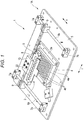
- Fig. 1 is a perspective view of the droplet dispensing apparatus 1 according to the first embodiment.
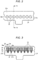
- Fig. 2 is a top view of a droplet ejecting device 2, which is mounted in the droplet dispensing apparatus 1.
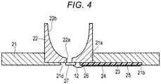
- Fig. 3 is a bottom view a surface of the droplet ejecting device 2 from which droplets are discharged.
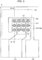
- Fig. 4 is a cross-sectional view taken along line F4-F4 in Fig. 2 .
- Fig. 5 is a plan view of a droplet ejecting array 27 of the droplet ejecting device 2.
- Fig. 6 is a cross-sectional view taken along line F6-F6 in Fig. 5 .
- Fig. 7 is a schematic diagram of a droplet detection unit 230 of the droplet dispensing apparatus 1.
- Fig. 8 is a diagram illustrating ejection timing for different nozzle groups in the droplet dispensing apparatus 1.
- Fig. 9 is a diagram for explaining an operation of the droplet detection unit 230 of the droplet dispensing apparatus 1.
- Fig. 10 is a diagram illustrating adjusted ejection timings for different nozzle groups and drive pulses applied to the respective nozzle groups in the droplet dispensing apparatus 1.
- the droplet dispensing apparatus 1 has a main body 1A, which includes a base plate 3 of the rectangular plate shape and a mounting module 5.
- a microplate 4 which may also be referred to as a receiving portion, a multiwell plate, or a microwell plate in some contexts, has 96 wells into which a solution can be dispensed. Microplates having 96 wells are commonly used in a biochemistry research and clinical examination. However, the microplate 4 is not limited to having 96 wells and may have any other number of wells, such as 384 wells, 1536 wells, 3456 wells, or 6144 wells.
- the microplate 4 is located at a middle position of the base plate 3 and can be secured to and detached from a plate attaching portion 3a of the base plate 3.
- a pair X-direction guide rails 6a and 6b extending in the X-direction is provided at both sides of the microplate 4.
- the ends of each of the X-direction guide rails 6a and 6b are respectively fixed to fixing supports 7a and 7b protruding on the base plate 3.
- a Y-direction guide rail 8 extending in the Y-direction is provided between the X-direction guide rails 6a and 6b. Both ends of the Y-direction guide rail 8 are respectively fixed to X-direction movable supports 9 which can slide in the X-direction along the X-direction guide rails 6a and 6b.
- a Y-direction movable support 10 is provided, on which the mounting module 5 is movable in the Y-direction along the Y-direction guide rail 8.
- the mounting module 5 is mounted on the Y-direction movable support 10.
- the droplet ejecting device 2, which serves as a droplet ejecting unit, is fixed to the mounting module 5.
- the droplet ejecting device 2 can move to any position in the X- and Y-directions, which are orthogonal to each other in this instance, by a combination of a movement of the Y-direction movable support 10 moving in the Y-direction along the Y-direction guide rail 8 and a movement of the X-direction movable supports 9 moving in the X-direction along the X-direction guide rails 6a and 6b.
- the droplet ejecting device 2 can be configured to be detachably mounted on the mounting module 5.
- the droplet ejecting device 2 has a flat base plate 21. As illustrated in Fig. 2 , on a top surface of the base plate 21 eight solution holding containers 22 are arranged side by side in a line in the Y-direction. In some embodiments, the base plate 21 may have more or less than eight solution holding containers 22. Each of the solution holding containers 22 is a bottomed cylindrically-shaped container with an open top surface as illustrated in Fig. 4 . On the top surface of the base plate 21, cylindrically-shaped recessed portions 21a are formed at positions corresponding to the respective solution holding containers 22. The bottom portion of each of the solution holding containers 22 is adhesively fixed to each of the recessed portions 21a.
- a solution outlet opening 22a (referred simply to as an opening hereinafter), through which solution is ejected, is formed at the central position.
- An opening area of a top opening 22b is larger than an opening area of the solution outlet opening 22a.
- an electrical circuit board 23 is provided at each of the solution holding containers 22.
- Each of the electrical circuit boards 23 is a rectangular flat plate member.
- a rectangular recessed portion 21b for mounting the electrical circuit board 23 and a droplet ejecting opening 21d communicating with the recessed portion 21b are formed. Circumference of the recessed portion 21b extends from the solution holding container 22 towards an upper end of the base plate 21 (an upper end in Fig. 3 and a right end in Fig. 4 ). A portion of the recessed portion 21b overlaps a part of the solution holding container 22 as illustrated in Fig. 4 .
- the electrical circuit board 23 is adhesively fixed to the recessed portion 21b.
- an electrical circuit board wiring 24 is patterned on a surface opposite to the recessed portion 21b.
- the electrical circuit board wiring 24 has three wiring patterns 24a, 24b, and 24c formed therein, which are respectively connected to a terminal portion 131c of a lower electrode 131 and two terminal portions 133c of an upper electrode 133.
- a control signal input terminal 25 for receiving an external control signal is formed.
- an electrode terminal connector 26 is formed. The electrode terminal connector 26 electrically connects the lower electrode terminal portion 131c and the upper electrode terminal portions 133c formed in the droplet ejecting array 27.
- the base plate 21 has a through-hole for the droplet ejecting opening 21d.
- the droplet ejecting opening 21d is a rectangular through-hole as illustrated in Fig. 3 , and is formed at a position overlapping the recessed portions 21a on the side of the back surface of the base plate 21.
- the droplet ejecting array 27 illustrated in Fig. 5 is adhesively fixed to the lower surface of the solution holding container 22 as to cover the solution outlet opening 22a of the solution holding container 22.
- the droplet ejecting array 27 is located at a position corresponding to the droplet ejecting opening 21d of the base plate 21.
- the droplet ejecting array 27 is formed by stacking a nozzle plate 100 and a pressure chamber structure 200 in layers.
- the nozzle plate 100 includes a nozzle 110 for discharging solution, a diaphragm 120, a drive element 130, a protective film 150, and a liquid-repellent film 160.
- An actuator 170 is formed with the diaphragm 120 and the drive element 130.
- the actuator 170 can be a piezoelectric element made from a lead-free material containing no lead component, or made from lead-containing material.
- the droplet ejecting array 27 has a nozzle group including a plurality of the nozzles 110 arranged side by side in a X-Y plane that is parallel to the X-direction and the Y-direction, as illustrated in Fig. 5 .
- three nozzles 110 are arranged in a vertical direction (also referred to as a first direction)
- four nozzles 110 are arranged in a horizontal direction (also referred to as a second direction)
- one set of twelve nozzles 110 arrayed in three rows and four columns is referred to as a "nozzle group 171".
- a plurality of nozzles 110 is arranged in each of the first direction and the second direction as illustrated in Fig. 5 .
- the terminal portion 131c of the lower electrode 131 is spaced from the nozzle group in the first direction, and the terminal portions 131c and other terminal portions 131c for other nozzle groups are aligned in the second direction.
- one nozzle group is located at a position corresponding to one opening 22a of one of the eight solution holding containers 22. Twelve nozzles 110 in one nozzle group 171 are arranged only within one well opening 4b of the microplate 4.
- the diaphragm 120 is formed, for example, integrally with the pressure chamber structure 200.
- the drive element 130 is formed for each nozzle 110.
- the drive element 130 has an annular shape surrounding the nozzle 110.
- the shape of the drive element 130 is not limited, and can be, for example, a C shape formed with a part of the circular ring removed.
- the diaphragm 120 deforms in the thickness direction thereof by an operation of the drive element 130, which is in a planar shape.
- the droplet ejecting device 2 ejects a solution supplied to each nozzle 110 according to a pressure change occurring in a pressure chamber 210 of the pressure chamber structure 200 due to the deformation of the diaphragm 120.
- the main body 1A of the droplet dispensing apparatus 1 includes a droplet detection unit 230 illustrated in Fig. 7 .
- the droplet detection unit 230 includes a light emitting unit 231, a light receiving unit (a light receiving sensor) 232, an ejection timing adjustment unit 234, and a control unit 235.
- the light emitting unit 231 includes, for example, a light source having a plurality of light-emitting diode (LED) elements arranged side by side.
- the light receiving unit 232 includes, for example, a charge-coupled device (CCD) camera.
- the control unit 235 includes, for example, a microprocessor and it connected to the light emitting unit 231 and the light receiving unit 232.
- the light emitting unit 231 and the light receiving unit 232 can be formed integrally in the droplet ejecting device 2, or may be provided in the mounting module 5.
- the light emitting unit 231 and the light receiving unit 232 are located on either sides of a plurality of nozzle groups each having twelve nozzles 110 (a first nozzle group 171a, closest to the light emitting unit 232, through an eighth nozzle group 171h, closest to the light receiving unit 232) arranged in a line in a third direction.
- An optical path 233 between the light emitting unit 231 and the light receiving unit 232 along the third direction intersects a trajectory of droplets ejected from the nozzles 110.
- the droplet detection unit 230 is driven by the control unit 235. Then, when droplets block light along the optical path 233, light intensity received by the light receiving unit 232 is reduced.
- the control unit 235 receives an output corresponding to the light intensity detected by the light receiving unit 232. When the detected light intensity is less than a specified amount, the control unit 235 detects droplets are being ejected from the nozzles 110.
- the optical path 233 is arranged obliquely with respect to the second direction along the columns of nozzles 110 in a nozzle group.
- the droplet ejecting array 27 is adhesively fixed to the droplet ejecting opening 21d of the base plate 21 of the droplet ejecting device 2, and located obliquely with respect to the base plate 21.
- control unit 235 includes the ejection timing adjustment unit 234, which controls timing of ejecting of droplets from the droplet ejecting device 2.
- the ejection timing adjustment unit 234 adjusts ejection timing of droplets from the eight nozzle groups 171 (nozzle groups 171a to 171h) at different timings.
- Fig. 8 is a diagram illustrating ejection timings for different nozzle groups.
- the ordinate axis indicates an ejection time
- the abscissa axis indicates the drive electrodes for the eight nozzle groups (the first nozzle group 171a to the eighth nozzle group 171h) of the droplet ejecting device 2.
- the label "a" indicates the first nozzle group 171a
- label "b” indicates the second nozzle group 171b and so forth up to label "h” that indicates the eighth nozzle group 171h.
- the ejection timing adjustment unit 234 adjusts ejection timings for the eight nozzle groups 171 (the first nozzle group 171a through the eighth nozzle group 171h) to different timings.
- Fig. 10 illustrates adjusted ejection timings for the of nozzle groups and drive pulses to be applied to the respective nozzle groups at the adjusted ejection timings.
- the control unit 235 applies a drive pulse having a pulse width t1 and a voltage Vt to drive the first nozzle group 171a.
- control unit 235 applies a drive pulse having a pulse width t1 and a voltage Vt to drive the second nozzle group 171b after elapse of a predetermined interval t2.
- control unit 235 sequentially applies drive pulses (each having a pulse width t1 and a voltage Vt to drive the third nozzle group 171c through the eighth nozzle group 171h at intervals of the predetermined interval t2.
- drive pulses each having a pulse width t1 and a voltage Vt to drive the third nozzle group 171c through the eighth nozzle group 171h at intervals of the predetermined interval t2.
- the control unit 235 re-applies a drive pulse having the pulse width t1 and the voltage Vt to drive the first nozzle group 171a. After that, the control unit 235 sequentially applies drive pulses each having the pulse width t1 and the voltage Vt to the drive the second nozzle group 171b through the eighth nozzle group 171h at the predetermined intervals t2.
- the droplet ejecting array 27 of the droplet ejecting device 2 is mounted on the mounting module 5.
- a predetermined amount of solution is supplied to the solution holding container 22 from the top open portion 22b of the solution holding container 22 by a pipette or the like (not illustrated).
- the solution is held at the inner surface of the solution holding container 22.
- the opening portion 22a at the bottom portion of the solution holding container 22 communicates with the droplet ejecting array 27.
- the solution held in the solution holding container 22 flows into each pressure chamber 210 of the droplet ejecting array 27 via the opening portion 22a.
- a voltage control signal that is input to the control signal input terminal 25 is transmitted from the electrode terminal connector 26 to the terminal portion 131c of the lower electrode 131 and the terminal portions 133c of the upper electrode 133.
- the diaphragm 120 deforms to change the volume of the pressure chamber 210, so that the solution is ejected as solution droplets from the nozzle 110 of the droplet ejecting array 27.
- the solution droplets are simultaneously dropped from twelve nozzles 110 to one well opening 4b of the microplate 4.
- a predetermined amount of solution is dropped from the nozzle 110 to each well opening 4b of the microplate 4.
- An amount of solution that is dropped is controlled by a number of repetitions of one-droplet dropping from each nozzle 110, and thus it is possible to control dropping of solution on the order of picoliter (pL) to microliter ( ⁇ L).
- the droplet detection unit 230 and the ejection timing adjustment unit 234 are driven during an operation of solution dropping from the nozzles 110 of the droplet ejecting array 27.
- the droplet detection unit 230 detects droplets are being ejected from the nozzles 110 by detecting a reduction in the light intensity detected by the light receiving unit 232 when light in the optical path 233 is blocked by the droplets.
- one nozzle group has twelve nozzles 110 arrayed in three rows and four columns located along the optical path 233 between the light emitting unit 231 and the light receiving unit 232.
- the nozzle 110 in which clogging occurs is referred to as a "nozzle 110q".
- the nozzle 110q is unavailable to drop droplets.
- the optical path 233 between the light emitting unit 231 and the light receiving unit 232 is located obliquely with respect to the second direction along the columns of nozzles 110 in the nozzle group. Therefore, all droplets dropped from the twelve nozzles 110 arrayed in three rows by four columns of one nozzle group can be simultaneously detected by the light receiving unit 232. For example, when droplets are dropped from nozzles 110 other than the nozzle 1 10q, a reduction in the light intensity is detected by the light receiving unit 232. However, since no droplets are dropped from the nozzle 110q, there is no reduction in the light intensity received by the light receiving unit 232 at the position corresponding to the nozzle 110q. Based on the detected light intensity by the light receiving unit 232, the nozzle 110q which is clogged can be detected.
- the eight nozzle groups are arranged along the optical path 233 between the light emitting unit 231 and the light receiving unit 232.
- the control unit 235 combines detecting droplets being ejected from one nozzle group and adjusting ejection timings of different nozzle groups by the ejection timing adjustment unit 234.
- the control unit 235 adjusts ejection timings for the eight nozzle groups 171. For example, as illustrated in Fig. 8 , the control unit 235 first drives the first nozzle group 171a. After driving of the first nozzle group 171a and an elapse of a predetermined interval, the control unit 235 drives the second nozzle group 171b. The control unit 235 sequentially drives the remaining nozzle groups, the third nozzle group 171c through the eighth nozzle group 171h, at the predetermined interval.
- the droplet detection unit 230 is driven at the time of an operation of dropping droplets from the nozzles 110 of the droplet ejecting array 27.
- the optical path 233 between the light emitting unit 231 and the light receiving unit 232 is located obliquely with respect to the second direction along the columns of the nozzles 110 in one nozzle group 171 of the droplet ejecting array 27.
- the control unit 235 can simultaneously detect, via the light receiving unit 232, all droplets dropped from the twelve nozzles 110 arrayed in one nozzle group, and thus can detect a nozzle 110 that does not discharge based on light intensity detected by the light receiving unit 232.
- the control unit 235 can detect an ejection failure, such as clogging, in a nozzle 110.
- the control unit 235 can promptly stop dropping solution from the nozzles 110.
- control unit 235 can promptly stop, for example, in a dose-response experiment, thus contributing to reduction or prevention of a waste, and early error detection in evaluation results of drug performance.
- control unit 235 can promptly stop, for example, in a dose-response experiment, thus contributing to reduction or prevention of a waste, and early error detection in evaluation results of drug performance.
- the droplet dispensing apparatus 1 has the ejection timing adjustment unit 234.
- the control unit 235 adjusts ejection timings for the eight nozzle groups 171. For example, as illustrated in Fig. 8 , the control unit 235 first drives the first nozzle group 171a. After driving the first nozzle group 171a and an elapse of a predetermined interval, the control unit 235 drives the second nozzle group 171b. The control unit 235 sequentially drives the remaining nozzle groups, the third nozzle group 171c through the eighth nozzle group 171h, at the predetermined intervals.
- the control unit 235 can individually detect droplets being ejected from the eight nozzle groups 171.
- a piezoelectric element may be made of a lead-free material that is lower in piezoelectric property than a piezoelectric element including a lead component, for example, PZT (Pb(Zr,Ti)O 3 : lead zirconate titanate), which contains a lead component. Therefore, in the case of using the piezoelectric element made of a lead-free material, since the amount of displacement of the diaphragm 120 when being driven is smaller than that of the piezoelectric element made from PZT, an amount of solution per one droplet is small.
- PZT Pb(Zr,Ti)O 3 : lead zirconate titanate
- a plurality of nozzles 110 (twelve arrayed in three rows and four columns) is disposed in one nozzle group for one well opening 4b.
- dropping of a required amount of solution can be completed in a short time even with use of the piezoelectric element having a lower piezoelectric property. Therefore, dropping of a required amount of solution can be completed in a short time even with respect to all well openings 4b of the microplate 4.
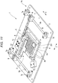
- Fig. 11 illustrates a droplet detection unit of a droplet dispensing apparatus according to a second embodiment.
- the droplet dispensing apparatus 1 according to the first embodiment is modified as follows.
- the same reference numerals are used for the components that are substantially the same as those of the first embodiment, and the detailed description of repeated components may be omitted.
- a second droplet ejecting unit 251 in addition to the droplet ejecting array 27 is provided.
- the second droplet ejecting unit 251 is provided with a supporting mechanism which supports the second droplet ejecting unit 251 in such a way as to be movable to any position in the X- and Y-directions separately from the droplet ejecting device 2.
- the second droplet ejecting unit 251 includes, for example, a water tank (not specifically illustrated).
- the second droplet ejecting unit 251 may include a tank that contains the same solution as that contained in the droplet ejecting array 27.
- solution or water is additionally ejected from the second droplet ejecting unit 251 into each well opening 4b of the microplate 4. This makes it possible to prevent solution held in each well opening 4b of the microplate 4 from drying.
- cells may be dried by solution evaporation due to a prolonged dispensing time due to a large number of wells.
- the second droplet ejecting unit 251 in the second embodiment performs additional dispensing of a solution enables to prevent or reducing drying. This permits high-efficiency experiments to be performed by using a high-density microplate.
- the supporting mechanism for the second droplet ejecting unit 251 may be able to perform parallel processing of dispensing droplets while moving in parallel with or perpendicularly to the movement of the droplet ejecting array 27.
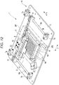
- Fig. 12 illustrates a droplet dispensing apparatus according to a third embodiment.
- the droplet dispensing apparatus 1 according to the first embodiment is modified as follows.
- the same reference numerals are used for the components that are substantially the same as those of the first embodiment, and the detailed description of repeated components may be omitted.
- a closed box component 261 encloses the microplate 4 and a spray device 262 spraying a humidifying solution inside the closed box component 261 on the base plate 3.
- the closed box component 261 includes, for example, a frame portion having a high-rigidity frame structure and a cover made from an elastic material closing a space between the framing parts of each frame.
- the closed box component 261 can be hermetically sealed by the frame portion and the cover.
- the spray device 262 includes, for example, a water tank (not illustrated).
- the spray device 262 may further include a tank that contains the same solution as that contained in the droplet ejecting array 27.
- the spray device 262 is located inside the closed box component 261, and sprays solution to the internal space of the closed box component 261 for drying prevention.
- droplets for preventing drying are sprayed from the spray device 262 to the internal space of the closed box component 261.
- the spray device 262 may be configured such that droplets for drying prevention are sprayed at the same time as the start of a solution dropping operation from the droplet ejecting array 27.
- Fig. 13 is a longitudinal cross-sectional view of a microplate 4 according to the fourth embodiment.
- a lid 271 made of an elastic material such as rubber is provided on the periphery of the well opening 4b.
- a notch 272 is formed as a slit at the central position of the opening of the well opening 4b.
- a needle-like injection member 273 is provided at the tip of the injection member 273, there is provided with an actuator which is capable of ejecting droplets in the order of pL.
- the opening of the well opening 4b is closed by the lid 271.
- the notch 272 of the lid 271 is closed.
- the tip of the injection member 273 is pressed into the notch 272 of the lid 271 as illustrated in Fig. 12 .
- the tip of the injection member 273 forces the notch 272 of the lid member 271 open.
- the lid 271 elastically deforms such that the peripheral portion on both sides of the notch 272 are pushed into the inside of the well opening 4b. Therefore, droplets are ejected from the tip of the injection member 273 while the tip of the injection member 273 is inserted into the well opening 4b.
- the injection member 273 is withdrawn to the outside of the microplate 4.
- the lid 271 elastically returns to a state in which the peripheral portions on both sides of the notch 272 are closed. Therefore, the well opening 4b of the microplate 4 is closed by the lid 271.
- the internal space of the well opening 4b of the microplate 4 is kept in an airtight state by the lid 271, droplets injected into the well opening 4b of the microplate 4 are prevented from evaporating.
Landscapes
- Chemical & Material Sciences (AREA)
- Health & Medical Sciences (AREA)
- Clinical Laboratory Science (AREA)
- Chemical Kinetics & Catalysis (AREA)
- Dispersion Chemistry (AREA)
- Analytical Chemistry (AREA)
- General Health & Medical Sciences (AREA)
- Hematology (AREA)
- Automatic Analysis And Handling Materials Therefor (AREA)
- Ink Jet (AREA)
- Particle Formation And Scattering Control In Inkjet Printers (AREA)
Abstract
A droplet dispensing apparatus includes a droplet ejecting array having a plurality of nozzle groups (171a-171h), each nozzle group including a plurality of nozzles arranged in columns in a first direction and rows in a second direction that intersects the first direction, and the plurality of nozzles being arranged in a third direction, a light emitting unit (231) configured to emit light along an optical path in the third direction oblique with respect to the first direction, a light receiving unit (232) configured to receive light from the light emitting unit (231), the light receiving unit (232) being on an opposite side of the droplet ejecting array from the light emitting unit (231), and a controller (234) configured to receive signals from the light receiving unit (232) according to light intensity as detected by the light receiving unit, and adjust ejection timings (234) such that each of the plurality of nozzle groups (171a-171h) ejects at a different timing.
Description
- Embodiments described herein relate generally to the field of microanalysis, and more particularly to a droplet dispensing apparatus and an analytic system comprising the same.
- For use in biological and pharmaceutical research and development, medical diagnosis or testing, or agricultural experiment, analytic devices and testing methods involving dispensing solution in volumes with in a picoliter (pL) to microliter (µL) range are often used.
- For improved speed in testing and evaluation, a droplet ejecting device typically ejects liquid droplets simultaneously from multiple nozzles into different wells of a microplate (also referred to as a multi-well plate) or the like.
- When liquid droplets are being dispensed simultaneously from a plurality of nozzles, there is a possibility that some of nozzles may not discharge the liquid as intended. In such a case, the intended amount of liquid is not dispensed from malfunctioning nozzle, which may cause erroneous evaluation results in some testing applications.
- To solve the above-cited problems, there is provided a droplet dispensing apparatus comprising:
- a droplet ejecting array having a plurality of nozzle groups, from each of which solution can be ejected into a well opening of a microplate on a baseline, each nozzle group including a plurality of nozzles arranged in columns in a first direction and rows in a second direction that intersects the first direction, and the plurality of nozzles being arranged in a line in a third direction;
- a light emitting unit configured to emit light along an optical path in the third direction oblique with respect to the first direction and the second direction;
- a light receiving unit disposed along the optical path and configured to receive light from the light emitting unit, the light receiving unit being on an opposite side of the droplet ejecting array from the light emitting unit; and
- a controller configured to
- receive signals from the light receiving unit according to light intensity as detected by the light receiving unit, and
- adjust ejection timings such that each of the plurality of nozzle groups ejects at a different timing.
- In an exemplary embodiment preferably the controller may adjust ejection timings for the plurality of nozzle groups such that solutions being ejected from any two nozzle groups in the plurality of nozzle groups do not overlap along the optical path.
- The droplet dispensing apparatus according to the embodiments preferably may further comprise a droplet ejection unit configured to dispense liquid towards the base plate.
- The droplet dispensing apparatus according to the embodiments preferably may further comprise:
- a sealed box enclosing the droplet ejection array and at least a portion of the base plate; and
- a spraying device and configured to spray a liquid into the sealed box.
- The droplet dispensing apparatus according to the embodiments preferably may further comprise a needle-like ejection member on the droplet ejection array configured to engage and open a lid on a periphery of a well opening of the microplate.
- The droplet dispensing apparatus according to the embodiments preferably may further comprise a base plate on which the microplate can be disposed.
- The droplet dispensing apparatus according to the embodiments preferably may further comprise:
- a plurality of pressure chambers on the base plate, each pressure chamber in the plurality being fluidly connected to a respective nozzle in the plurality of nozzle groups;
- a plurality of actuators configured to change pressure in the pressure chamber and cause solution to be ejected from the pressure chamber from the respective nozzle; and
- a plurality of solution holding containers on the base plate, each having a solution receiving port for receiving solution and a solution outlet port for supplying solution to the pressure chamber.
- Preferably in the embodiments each of the plurality of actuators may be configured with a piezoelectric element of a lead-free material.
- The droplet dispensing apparatus according to the embodiments preferably may further comprise a mounting module to which the droplet ejecting array can be detachably attached.
- In another exemplary embodiment there is also provided an analytic system comprising the droplet dispensing apparatus according to the embodiments.
- The above and other objects, features and advantages of the present invention will be made apparent from the following description of the preferred embodiments, given as non-limiting examples, with reference to the accompanying drawings, in which:
-
Fig. 1 is a perspective view of a droplet dispensing apparatus according to a first embodiment. -
Fig. 2 is a top view illustrating of a droplet ejecting device of a droplet dispensing apparatus. -
Fig. 3 is a bottom view of a droplet ejecting device of a droplet dispensing apparatus. -
Fig. 4 is a cross-sectional view taken along line F4-F4 inFig. 2 . -
Fig. 5 is a plan view of a droplet ejecting array of a droplet ejecting device. -
Fig. 6 is a cross-sectional view taken along line F6-F6 inFig. 5 . -
Fig. 7 is a schematic diagram of a droplet detection unit of a droplet dispensing apparatus. -
Fig. 8 is a diagram illustrating ejection timings for different nozzle groups. -
Fig. 9 is a diagram for explaining an operation of a droplet detection unit of the droplet dispensing apparatus. -
Fig. 10 is a diagram illustrating adjusted ejection timings for different nozzle groups and drive pulses applied to respective nozzle groups. -
Fig. 11 is a perspective view of a droplet dispensing apparatus according to a second embodiment. -
Fig. 12 is a perspective view of a droplet dispensing apparatus according to a third embodiment. -
Fig. 13 is a cross-sectional view of a microplate. - In general, according to one embodiment, a droplet dispensing apparatus includes a droplet ejecting array having a plurality of nozzle groups, from each of which solution can be ejected into a well opening of a microplate on a baseline, each nozzle group including a plurality of nozzles arranged in columns in a first direction and rows in a second direction that intersects the first direction, and the plurality of nozzles being arranged in a line in a third direction, a light emitting unit configured to emit light along an optical path in the third direction oblique with respect to the first direction and the second direction, a light receiving unit disposed along the optical path and configured to receive light from the light emitting unit, the light receiving unit being on an opposite side of the droplet ejecting array from the light emitting unit, and a controller configured to receive signals from the light receiving unit according to light intensity as detected by the light receiving unit, and adjust ejection timings such that each of the plurality of nozzle groups ejects at a different timing.
- Hereinafter, droplet dispensing apparatuses according to example embodiments will be described with reference to the drawings. It should be noted, that the particular embodiments explained below are some possible examples of a droplet dispensing apparatus according to the present disclosure and do not limit the possible configurations, specifications, or the like of droplet dispensing apparatuses according to the present disclosure.
- An example of a droplet dispensing apparatus 1 according to a first embodiment is described with reference to
Fig. 1 through Fig. 10 .Fig. 1 is a perspective view of the droplet dispensing apparatus 1 according to the first embodiment.Fig. 2 is a top view of adroplet ejecting device 2, which is mounted in the droplet dispensing apparatus 1.Fig. 3 is a bottom view a surface of the droplet ejectingdevice 2 from which droplets are discharged.Fig. 4 is a cross-sectional view taken along line F4-F4 inFig. 2 .Fig. 5 is a plan view of adroplet ejecting array 27 of thedroplet ejecting device 2.Fig. 6 is a cross-sectional view taken along line F6-F6 inFig. 5 .Fig. 7 is a schematic diagram of adroplet detection unit 230 of the droplet dispensing apparatus 1.Fig. 8 is a diagram illustrating ejection timing for different nozzle groups in the droplet dispensing apparatus 1.Fig. 9 is a diagram for explaining an operation of thedroplet detection unit 230 of the droplet dispensing apparatus 1.Fig. 10 is a diagram illustrating adjusted ejection timings for different nozzle groups and drive pulses applied to the respective nozzle groups in the droplet dispensing apparatus 1. - The droplet dispensing apparatus 1 has a
main body 1A, which includes a base plate 3 of the rectangular plate shape and amounting module 5. In the present embodiment, amicroplate 4, which may also be referred to as a receiving portion, a multiwell plate, or a microwell plate in some contexts, has 96 wells into which a solution can be dispensed. Microplates having 96 wells are commonly used in a biochemistry research and clinical examination. However, themicroplate 4 is not limited to having 96 wells and may have any other number of wells, such as 384 wells, 1536 wells, 3456 wells, or 6144 wells. - The
microplate 4 is located at a middle position of the base plate 3 and can be secured to and detached from aplate attaching portion 3a of the base plate 3. A pairX-direction guide rails microplate 4. The ends of each of theX-direction guide rails supports - A Y-
direction guide rail 8 extending in the Y-direction is provided between theX-direction guide rails direction guide rail 8 are respectively fixed to X-directionmovable supports 9 which can slide in the X-direction along theX-direction guide rails - A Y-direction
movable support 10 is provided, on which the mountingmodule 5 is movable in the Y-direction along the Y-direction guide rail 8. The mountingmodule 5 is mounted on the Y-directionmovable support 10. Thedroplet ejecting device 2, which serves as a droplet ejecting unit, is fixed to the mountingmodule 5. Thus, thedroplet ejecting device 2 can move to any position in the X- and Y-directions, which are orthogonal to each other in this instance, by a combination of a movement of the Y-directionmovable support 10 moving in the Y-direction along the Y-direction guide rail 8 and a movement of the X-directionmovable supports 9 moving in the X-direction along theX-direction guide rails droplet ejecting device 2 can be configured to be detachably mounted on the mountingmodule 5. - The
droplet ejecting device 2 according to the first embodiment has aflat base plate 21. As illustrated inFig. 2 , on a top surface of thebase plate 21 eightsolution holding containers 22 are arranged side by side in a line in the Y-direction. In some embodiments, thebase plate 21 may have more or less than eightsolution holding containers 22. Each of thesolution holding containers 22 is a bottomed cylindrically-shaped container with an open top surface as illustrated inFig. 4 . On the top surface of thebase plate 21, cylindrically-shaped recessedportions 21a are formed at positions corresponding to the respectivesolution holding containers 22. The bottom portion of each of thesolution holding containers 22 is adhesively fixed to each of the recessedportions 21a. Furthermore, on the bottom portion of thesolution holding container 22, asolution outlet opening 22a (referred simply to as an opening hereinafter), through which solution is ejected, is formed at the central position. An opening area of atop opening 22b is larger than an opening area of thesolution outlet opening 22a. - As illustrated in
Fig. 3 , on a bottom surface of thebase plate 21, anelectrical circuit board 23 is provided at each of thesolution holding containers 22. Each of theelectrical circuit boards 23 is a rectangular flat plate member. On the side of the back surface of thebase plate 21. As illustrated inFig. 4 , a rectangular recessedportion 21b for mounting theelectrical circuit board 23 and adroplet ejecting opening 21d communicating with the recessedportion 21b are formed. Circumference of the recessedportion 21b extends from thesolution holding container 22 towards an upper end of the base plate 21 (an upper end inFig. 3 and a right end inFig. 4 ). A portion of the recessedportion 21b overlaps a part of thesolution holding container 22 as illustrated inFig. 4 . Theelectrical circuit board 23 is adhesively fixed to the recessedportion 21b. - On the
electrical circuit board 23, an electricalcircuit board wiring 24 is patterned on a surface opposite to the recessedportion 21b. The electricalcircuit board wiring 24 has threewiring patterns terminal portion 131c of a lower electrode 131 and twoterminal portions 133c of an upper electrode 133. - At one end portion of the electrical
circuit board wiring 24, a controlsignal input terminal 25 for receiving an external control signal is formed. At the other end portion of the electricalcircuit board wiring 24, anelectrode terminal connector 26 is formed. Theelectrode terminal connector 26 electrically connects the lowerelectrode terminal portion 131c and the upperelectrode terminal portions 133c formed in thedroplet ejecting array 27. - Furthermore, the
base plate 21 has a through-hole for thedroplet ejecting opening 21d. Thedroplet ejecting opening 21d is a rectangular through-hole as illustrated inFig. 3 , and is formed at a position overlapping the recessedportions 21a on the side of the back surface of thebase plate 21. - The
droplet ejecting array 27 illustrated inFig. 5 is adhesively fixed to the lower surface of thesolution holding container 22 as to cover the solution outlet opening 22a of thesolution holding container 22. Thedroplet ejecting array 27 is located at a position corresponding to thedroplet ejecting opening 21d of thebase plate 21. - As illustrated in
Fig. 6 , thedroplet ejecting array 27 is formed by stacking anozzle plate 100 and apressure chamber structure 200 in layers. Thenozzle plate 100 includes anozzle 110 for discharging solution, adiaphragm 120, adrive element 130, aprotective film 150, and a liquid-repellent film 160. Anactuator 170 is formed with thediaphragm 120 and thedrive element 130. In the present embodiment, theactuator 170 can be a piezoelectric element made from a lead-free material containing no lead component, or made from lead-containing material. - The
droplet ejecting array 27 has a nozzle group including a plurality of thenozzles 110 arranged side by side in a X-Y plane that is parallel to the X-direction and the Y-direction, as illustrated inFig. 5 . In the example embodiment described herein, threenozzles 110 are arranged in a vertical direction (also referred to as a first direction), fournozzles 110 are arranged in a horizontal direction (also referred to as a second direction), and one set of twelvenozzles 110 arrayed in three rows and four columns is referred to as a "nozzle group 171". In other words, in the present embodiment, a plurality ofnozzles 110 is arranged in each of the first direction and the second direction as illustrated inFig. 5 . Theterminal portion 131c of the lower electrode 131 is spaced from the nozzle group in the first direction, and theterminal portions 131c and otherterminal portions 131c for other nozzle groups are aligned in the second direction. - Furthermore, in the
droplet ejecting array 27 according to the present embodiment, one nozzle group is located at a position corresponding to oneopening 22a of one of the eightsolution holding containers 22. Twelvenozzles 110 in one nozzle group 171 are arranged only within onewell opening 4b of themicroplate 4. - The
diaphragm 120 is formed, for example, integrally with thepressure chamber structure 200. Thedrive element 130 is formed for eachnozzle 110. Thedrive element 130 has an annular shape surrounding thenozzle 110. The shape of thedrive element 130 is not limited, and can be, for example, a C shape formed with a part of the circular ring removed. - The
diaphragm 120 deforms in the thickness direction thereof by an operation of thedrive element 130, which is in a planar shape. Thedroplet ejecting device 2 ejects a solution supplied to eachnozzle 110 according to a pressure change occurring in apressure chamber 210 of thepressure chamber structure 200 due to the deformation of thediaphragm 120. - The
main body 1A of the droplet dispensing apparatus 1 includes adroplet detection unit 230 illustrated inFig. 7 . Thedroplet detection unit 230 includes alight emitting unit 231, a light receiving unit (a light receiving sensor) 232, an ejectiontiming adjustment unit 234, and acontrol unit 235. Thelight emitting unit 231 includes, for example, a light source having a plurality of light-emitting diode (LED) elements arranged side by side. Furthermore, thelight receiving unit 232 includes, for example, a charge-coupled device (CCD) camera. Thecontrol unit 235 includes, for example, a microprocessor and it connected to thelight emitting unit 231 and thelight receiving unit 232. Thelight emitting unit 231 and thelight receiving unit 232 can be formed integrally in thedroplet ejecting device 2, or may be provided in the mountingmodule 5. - As illustrated in
Fig. 7 , thelight emitting unit 231 and thelight receiving unit 232 are located on either sides of a plurality of nozzle groups each having twelve nozzles 110 (afirst nozzle group 171a, closest to thelight emitting unit 232, through aneighth nozzle group 171h, closest to the light receiving unit 232) arranged in a line in a third direction. Anoptical path 233 between thelight emitting unit 231 and thelight receiving unit 232 along the third direction intersects a trajectory of droplets ejected from thenozzles 110. - Along the
optical path 233, horizontally-polarized light is emitted from thelight emitting unit 231 toward thelight receiving unit 232. Thedroplet detection unit 230 is driven by thecontrol unit 235. Then, when droplets block light along theoptical path 233, light intensity received by thelight receiving unit 232 is reduced. Thecontrol unit 235 receives an output corresponding to the light intensity detected by thelight receiving unit 232. When the detected light intensity is less than a specified amount, thecontrol unit 235 detects droplets are being ejected from thenozzles 110. - In the
main body 1A of the droplet dispensing apparatus 1, theoptical path 233 is arranged obliquely with respect to the second direction along the columns ofnozzles 110 in a nozzle group. In the example embodiment described herein, thedroplet ejecting array 27 is adhesively fixed to thedroplet ejecting opening 21d of thebase plate 21 of thedroplet ejecting device 2, and located obliquely with respect to thebase plate 21. - Furthermore, the
control unit 235 includes the ejectiontiming adjustment unit 234, which controls timing of ejecting of droplets from thedroplet ejecting device 2. The ejectiontiming adjustment unit 234 adjusts ejection timing of droplets from the eight nozzle groups 171 (nozzle groups 171a to 171h) at different timings. - The
terminal portion 131c of the lower electrode 131 and theterminal portions 133c of the upper electrode 133 are formed for each of the eight nozzle groups and are connected to the ejectiontiming adjustment unit 234 via the electricalcircuit board wiring 24.Fig. 8 is a diagram illustrating ejection timings for different nozzle groups. InFig. 8 , the ordinate axis indicates an ejection time, and the abscissa axis indicates the drive electrodes for the eight nozzle groups (thefirst nozzle group 171a to theeighth nozzle group 171h) of thedroplet ejecting device 2. InFig. 8 , the label "a" indicates thefirst nozzle group 171a, and label "b" indicates thesecond nozzle group 171b and so forth up to label "h" that indicates theeighth nozzle group 171h. - As illustrated in
Fig. 8 , the ejectiontiming adjustment unit 234 adjusts ejection timings for the eight nozzle groups 171 (thefirst nozzle group 171a through theeighth nozzle group 171h) to different timings. -
Fig. 10 illustrates adjusted ejection timings for the of nozzle groups and drive pulses to be applied to the respective nozzle groups at the adjusted ejection timings. As illustrated inFig. 10 , when a start button or the like is pressed, at time t0, thecontrol unit 235 applies a drive pulse having a pulse width t1 and a voltage Vt to drive thefirst nozzle group 171a. - After that, the
control unit 235 applies a drive pulse having a pulse width t1 and a voltage Vt to drive thesecond nozzle group 171b after elapse of a predetermined interval t2. - Subsequently, the
control unit 235 sequentially applies drive pulses (each having a pulse width t1 and a voltage Vt to drive thethird nozzle group 171c through theeighth nozzle group 171h at intervals of the predetermined interval t2. After the eighth nozzle group 217h is driven, a sequence of the drive pluses to drive the first nozzle group 217a through the eighth nozzle group 217h is repeated. - That is, after the
eighth nozzle group 171h has been driven at time t0+8×(t1+t2), thecontrol unit 235 re-applies a drive pulse having the pulse width t1 and the voltage Vt to drive thefirst nozzle group 171a. After that, thecontrol unit 235 sequentially applies drive pulses each having the pulse width t1 and the voltage Vt to the drive thesecond nozzle group 171b through theeighth nozzle group 171h at the predetermined intervals t2. - In the droplet dispensing apparatus 1 according to the present embodiment, the
droplet ejecting array 27 of thedroplet ejecting device 2 is mounted on the mountingmodule 5. When thedroplet ejecting device 2 is use, a predetermined amount of solution is supplied to thesolution holding container 22 from the topopen portion 22b of thesolution holding container 22 by a pipette or the like (not illustrated). The solution is held at the inner surface of thesolution holding container 22. Theopening portion 22a at the bottom portion of thesolution holding container 22 communicates with thedroplet ejecting array 27. The solution held in thesolution holding container 22 flows into eachpressure chamber 210 of thedroplet ejecting array 27 via theopening portion 22a. - A voltage control signal that is input to the control
signal input terminal 25 is transmitted from theelectrode terminal connector 26 to theterminal portion 131c of the lower electrode 131 and theterminal portions 133c of the upper electrode 133. In response to the voltage control signal applied to thedrive element 130, thediaphragm 120 deforms to change the volume of thepressure chamber 210, so that the solution is ejected as solution droplets from thenozzle 110 of thedroplet ejecting array 27. In the present embodiment, the solution droplets are simultaneously dropped from twelvenozzles 110 to onewell opening 4b of themicroplate 4. Thus, a predetermined amount of solution is dropped from thenozzle 110 to each well opening 4b of themicroplate 4. - An amount of solution that is dropped is controlled by a number of repetitions of one-droplet dropping from each
nozzle 110, and thus it is possible to control dropping of solution on the order of picoliter (pL) to microliter (µL). - In the present embodiment, the
droplet detection unit 230 and the ejectiontiming adjustment unit 234 are driven during an operation of solution dropping from thenozzles 110 of thedroplet ejecting array 27. Thedroplet detection unit 230 detects droplets are being ejected from thenozzles 110 by detecting a reduction in the light intensity detected by thelight receiving unit 232 when light in theoptical path 233 is blocked by the droplets. - An operation of detecting droplets via the
droplet detection unit 230 in the present embodiment will be described with reference toFig. 9 . In the example illustrated inFig. 9 , one nozzle group has twelvenozzles 110 arrayed in three rows and four columns located along theoptical path 233 between thelight emitting unit 231 and thelight receiving unit 232. In a case where clogging occurs in at least onenozzle 110 among the twelvenozzles 110 in one nozzle group, thenozzle 110 in which clogging occurs is referred to as a "nozzle 110q". Thenozzle 110q is unavailable to drop droplets. - As illustrated in
Fig. 9 , in thedroplet detection unit 230, theoptical path 233 between thelight emitting unit 231 and thelight receiving unit 232 is located obliquely with respect to the second direction along the columns ofnozzles 110 in the nozzle group. Therefore, all droplets dropped from the twelvenozzles 110 arrayed in three rows by four columns of one nozzle group can be simultaneously detected by thelight receiving unit 232. For example, when droplets are dropped fromnozzles 110 other than the nozzle 1 10q, a reduction in the light intensity is detected by thelight receiving unit 232. However, since no droplets are dropped from thenozzle 110q, there is no reduction in the light intensity received by thelight receiving unit 232 at the position corresponding to thenozzle 110q. Based on the detected light intensity by thelight receiving unit 232, thenozzle 110q which is clogged can be detected. - Furthermore, as illustrated in
Fig. 7 , the eight nozzle groups are arranged along theoptical path 233 between thelight emitting unit 231 and thelight receiving unit 232. In the example embodiment described herein, thecontrol unit 235 combines detecting droplets being ejected from one nozzle group and adjusting ejection timings of different nozzle groups by the ejectiontiming adjustment unit 234. - During an operation of the ejection
timing adjustment unit 234, thecontrol unit 235 adjusts ejection timings for the eight nozzle groups 171. For example, as illustrated inFig. 8 , thecontrol unit 235 first drives thefirst nozzle group 171a. After driving of thefirst nozzle group 171a and an elapse of a predetermined interval, thecontrol unit 235 drives thesecond nozzle group 171b. Thecontrol unit 235 sequentially drives the remaining nozzle groups, thethird nozzle group 171c through theeighth nozzle group 171h, at the predetermined interval. - In the droplet dispensing apparatus 1 according to the first embodiment, the
droplet detection unit 230 is driven at the time of an operation of dropping droplets from thenozzles 110 of thedroplet ejecting array 27. In thedroplet detection unit 230 as illustrated inFig. 7 , theoptical path 233 between thelight emitting unit 231 and thelight receiving unit 232 is located obliquely with respect to the second direction along the columns of thenozzles 110 in one nozzle group 171 of thedroplet ejecting array 27. Therefore, thecontrol unit 235 can simultaneously detect, via thelight receiving unit 232, all droplets dropped from the twelvenozzles 110 arrayed in one nozzle group, and thus can detect anozzle 110 that does not discharge based on light intensity detected by thelight receiving unit 232. As a result, when solution is dropped simultaneously from twelvenozzles 110 arrayed in one nozzle group unto one well opening 4b of themicroplate 4, thecontrol unit 235 can detect an ejection failure, such as clogging, in anozzle 110. When a discharge failure is detected, and thus a predetermined amount of solution cannot be dropped from thedroplet ejecting array 27 into thewell opening 4b of themicroplate 4, thecontrol unit 235 can promptly stop dropping solution from thenozzles 110. Thus, thecontrol unit 235 can promptly stop, for example, in a dose-response experiment, thus contributing to reduction or prevention of a waste, and early error detection in evaluation results of drug performance. As a result, it is possible to provide a droplet dispensing apparatus which can provide more accurate evaluation results of drugs performance. - In the example embodiment described herein, the droplet dispensing apparatus 1 has the ejection
timing adjustment unit 234. During an operation of the ejectiontiming adjustment unit 234, thecontrol unit 235 adjusts ejection timings for the eight nozzle groups 171. For example, as illustrated inFig. 8 , thecontrol unit 235 first drives thefirst nozzle group 171a. After driving thefirst nozzle group 171a and an elapse of a predetermined interval, thecontrol unit 235 drives thesecond nozzle group 171b. Thecontrol unit 235 sequentially drives the remaining nozzle groups, thethird nozzle group 171c through theeighth nozzle group 171h, at the predetermined intervals. - Accordingly, in the example embodiment described herein, when droplets are ejected from the eight nozzle groups 171 that are arrayed along the
optical path 233 between thelight emitting unit 231 and thelight receiving unit 232 of thedroplet detection unit 230, no two or more nozzle groups 171 among the eight nozzle groups 171 are driven at the same timing. Therefore, thelight receiving unit 232 detects droplets being dropped from one nozzle group at a time. As a result, even with eightnozzle groups 171h arranged in a line along theoptical path 233 between thelight emitting unit 231 and thelight receiving unit 232, thecontrol unit 235 can individually detect droplets being ejected from the eight nozzle groups 171. - A piezoelectric element may be made of a lead-free material that is lower in piezoelectric property than a piezoelectric element including a lead component, for example, PZT (Pb(Zr,Ti)O3: lead zirconate titanate), which contains a lead component. Therefore, in the case of using the piezoelectric element made of a lead-free material, since the amount of displacement of the
diaphragm 120 when being driven is smaller than that of the piezoelectric element made from PZT, an amount of solution per one droplet is small. - In the example embodiment described herein, a plurality of nozzles 110 (twelve arrayed in three rows and four columns) is disposed in one nozzle group for one
well opening 4b. Thus, dropping of a required amount of solution can be completed in a short time even with use of the piezoelectric element having a lower piezoelectric property. Therefore, dropping of a required amount of solution can be completed in a short time even with respect to allwell openings 4b of themicroplate 4. -
Fig. 11 illustrates a droplet detection unit of a droplet dispensing apparatus according to a second embodiment. In this example embodiment, the droplet dispensing apparatus 1 according to the first embodiment is modified as follows. The same reference numerals are used for the components that are substantially the same as those of the first embodiment, and the detailed description of repeated components may be omitted. - In the second embodiment, a second
droplet ejecting unit 251 in addition to thedroplet ejecting array 27 is provided. The seconddroplet ejecting unit 251 is provided with a supporting mechanism which supports the seconddroplet ejecting unit 251 in such a way as to be movable to any position in the X- and Y-directions separately from thedroplet ejecting device 2. - The second
droplet ejecting unit 251 includes, for example, a water tank (not specifically illustrated). The seconddroplet ejecting unit 251 may include a tank that contains the same solution as that contained in thedroplet ejecting array 27. - In the second embodiment, after a predetermined amount of solution has been dropped from the
droplet ejecting array 27 into each well opening 4b of themicroplate 4, after elapse of a preset time, solution (or water) is additionally ejected from the seconddroplet ejecting unit 251 into each well opening 4b of themicroplate 4. This makes it possible to prevent solution held in each well opening 4b of themicroplate 4 from drying. - For example, in a high-density microplate, cells may be dried by solution evaporation due to a prolonged dispensing time due to a large number of wells. In such a case, the second
droplet ejecting unit 251 in the second embodiment performs additional dispensing of a solution enables to prevent or reducing drying. This permits high-efficiency experiments to be performed by using a high-density microplate. - Furthermore, the supporting mechanism for the second
droplet ejecting unit 251 may be able to perform parallel processing of dispensing droplets while moving in parallel with or perpendicularly to the movement of thedroplet ejecting array 27. -
Fig. 12 illustrates a droplet dispensing apparatus according to a third embodiment. In this example embodiment, the droplet dispensing apparatus 1 according to the first embodiment is modified as follows. The same reference numerals are used for the components that are substantially the same as those of the first embodiment, and the detailed description of repeated components may be omitted. - In the third embodiment, a
closed box component 261 encloses themicroplate 4 and aspray device 262 spraying a humidifying solution inside theclosed box component 261 on the base plate 3. Theclosed box component 261 includes, for example, a frame portion having a high-rigidity frame structure and a cover made from an elastic material closing a space between the framing parts of each frame. Theclosed box component 261 can be hermetically sealed by the frame portion and the cover. - The
spray device 262 includes, for example, a water tank (not illustrated). Thespray device 262 may further include a tank that contains the same solution as that contained in thedroplet ejecting array 27. Thespray device 262 is located inside theclosed box component 261, and sprays solution to the internal space of theclosed box component 261 for drying prevention. - In the present embodiment, after a predetermined amount of solution has been dropped from the
droplet ejecting array 27 into each well opening 4b of themicroplate 4, when a preset time elapses, droplets for preventing drying are sprayed from thespray device 262 to the internal space of theclosed box component 261. Thespray device 262 may be configured such that droplets for drying prevention are sprayed at the same time as the start of a solution dropping operation from thedroplet ejecting array 27. - This makes it possible to prevent solution held in
well openings 4b of themicroplate 4 from drying or reducing. -
Fig. 13 is a longitudinal cross-sectional view of amicroplate 4 according to the fourth embodiment. In themicroplate 4 in the present modification example embodiment, alid 271 made of an elastic material such as rubber is provided on the periphery of thewell opening 4b. In thelid 271, anotch 272 is formed as a slit at the central position of the opening of thewell opening 4b. - Furthermore, in the
droplet ejecting array 27, a needle-like injection member 273 is provided. At the tip of theinjection member 273, there is provided with an actuator which is capable of ejecting droplets in the order of pL. - In the
microplate 4, in the standby state (when not in use), the opening of thewell opening 4b is closed by thelid 271. In this state, thenotch 272 of thelid 271 is closed. - At the time of an operation of solution dropping from the
droplet ejecting array 27, the tip of theinjection member 273 is pressed into thenotch 272 of thelid 271 as illustrated inFig. 12 . Thus, the tip of theinjection member 273 forces thenotch 272 of thelid member 271 open. At this time, thelid 271 elastically deforms such that the peripheral portion on both sides of thenotch 272 are pushed into the inside of thewell opening 4b. Therefore, droplets are ejected from the tip of theinjection member 273 while the tip of theinjection member 273 is inserted into thewell opening 4b. - Furthermore, after a specified amount of solution is ejected from the
injection member 273, theinjection member 273 is withdrawn to the outside of themicroplate 4. At this time, thelid 271 elastically returns to a state in which the peripheral portions on both sides of thenotch 272 are closed. Therefore, the well opening 4b of themicroplate 4 is closed by thelid 271. Thus, since the internal space of thewell opening 4b of themicroplate 4 is kept in an airtight state by thelid 271, droplets injected into thewell opening 4b of themicroplate 4 are prevented from evaporating. - As a result, solution held in each well opening 4b of the
microplate 4 can prevented from and drying is reduced. - While certain embodiments have been described, these embodiments have been presented by way of example only, and are not intended to limit the scope of the inventions. Indeed, the novel embodiments described herein may be embodied in a variety of other forms. Furthermore, various omissions, substitutions and changes in the form of the embodiments described herein may be made without departing from the scope of the inventions. The accompanying claims and their equivalents are intended to cover such forms or modifications as would fall within the scope of the inventions.
Claims (10)
- A droplet dispensing apparatus comprising:a droplet ejecting array having a plurality of nozzle groups, from each of which solution can be ejected into a well opening of a microplate on a baseline, each nozzle group including a plurality of nozzles arranged in columns in a first direction and rows in a second direction that intersects the first direction, and the plurality of nozzles being arranged in a line in a third direction;a light emitting unit configured to emit light along an optical path in the third direction oblique with respect to the first direction and the second direction;a light receiving unit disposed along the optical path and configured to receive light from the light emitting unit, the light receiving unit being on an opposite side of the droplet ejecting array from the light emitting unit; anda controller configured toreceive signals from the light receiving unit according to light intensity as detected by the light receiving unit, andadjust ejection timings such that each of the plurality of nozzle groups ejects at a different timing.
- The droplet dispensing apparatus according to claim 1, wherein the controller adjusts ejection timings for the plurality of nozzle groups such that solutions being ejected from any two nozzle groups in the plurality of nozzle groups do not overlap along the optical path.
- The droplet dispensing apparatus according to claim 1 or 2, further comprising a droplet ejection unit configured to dispense liquid towards the base plate.
- The droplet dispensing apparatus according to any one of claims 1 to 3, further comprising:a sealed box enclosing the droplet ejection array and at least a portion of the base plate; anda spraying device and configured to spray a liquid into the sealed box.
- The droplet dispensing apparatus according to any one of claims 1 to 4, further comprising a needle-like ejection member on the droplet ejection array configured to engage and open a lid on a periphery of a well opening of the microplate.
- The droplet dispensing apparatus according to any one of claims 1 to 5, further comprising a base plate on which the microplate can be disposed.
- The droplet dispensing apparatus according to any one of claims 1 to 6, further comprising:a plurality of pressure chambers on the base plate, each pressure chamber in the plurality being fluidly connected to a respective nozzle in the plurality of nozzle groups;a plurality of actuators configured to change pressure in the pressure chamber and cause solution to be ejected from the pressure chamber from the respective nozzle; anda plurality of solution holding containers on the base plate, each having a solution receiving port for receiving solution and a solution outlet port for supplying solution to the pressure chamber.
- The droplet dispensing apparatus according to claim 7, wherein each of the plurality of actuators is configured with a piezoelectric element of a lead-free material.
- The droplet dispensing apparatus according to any one of claims 1 to 8, further comprising a mounting module to which the droplet ejecting array can be detachably attached.
- An analytic system comprising the droplet dispensing apparatus according to any one of claims 1 to 9.
Applications Claiming Priority (1)
| Application Number | Priority Date | Filing Date | Title |
|---|---|---|---|
| JP2017059797A JP2018163017A (en) | 2017-03-24 | 2017-03-24 | Droplet dispensing device |
Publications (1)
| Publication Number | Publication Date |
|---|---|
| EP3378562A1 true EP3378562A1 (en) | 2018-09-26 |
Family
ID=61526721
Family Applications (1)
| Application Number | Title | Priority Date | Filing Date |
|---|---|---|---|
| EP18159398.9A Withdrawn EP3378562A1 (en) | 2017-03-24 | 2018-03-01 | Droplet dispensing apparatus |
Country Status (4)
| Country | Link |
|---|---|
| US (1) | US20180272345A1 (en) |
| EP (1) | EP3378562A1 (en) |
| JP (1) | JP2018163017A (en) |
| CN (1) | CN108620252A (en) |
Cited By (1)
| Publication number | Priority date | Publication date | Assignee | Title |
|---|---|---|---|---|
| EP3677921A1 (en) * | 2019-01-04 | 2020-07-08 | Funai Electric Co., Ltd. | Digital dispense system cartridge |
Families Citing this family (9)
| Publication number | Priority date | Publication date | Assignee | Title |
|---|---|---|---|---|
| JP7019344B2 (en) | 2017-08-22 | 2022-02-15 | 東芝テック株式会社 | Drug droplet drop device and drug solution discharge device |
| JP6925908B2 (en) | 2017-08-22 | 2021-08-25 | 東芝テック株式会社 | Drug droplet device |
| JP2019184495A (en) | 2018-04-13 | 2019-10-24 | 東芝テック株式会社 | Droplet dispensing device |
| US11474007B2 (en) | 2019-01-04 | 2022-10-18 | Funai Electric Co., Ltd. | Digital dispense system |
| US11471879B2 (en) | 2019-01-04 | 2022-10-18 | Funai Electric Co., Ltd. | Volume data representation and processing for liquid dispensing devices |
| US11331660B2 (en) * | 2019-01-04 | 2022-05-17 | Funai Electric Co. Ltd. | Digital dispense system |
| CN110488028A (en) * | 2019-08-28 | 2019-11-22 | 北京慧荣和科技有限公司 | A kind of ultra micro quantity of fluid sample adding device |
| CN116899776B (en) * | 2023-08-10 | 2026-01-06 | 广州华创精密科技有限公司 | Spraying equipment and its working method |
| US12669455B2 (en) * | 2024-03-21 | 2026-06-30 | Brady Worldwide, Inc. | Method and apparatus for determining water content of hygroscopic fluids |
Citations (4)
| Publication number | Priority date | Publication date | Assignee | Title |
|---|---|---|---|---|
| JPH10193643A (en) * | 1997-01-14 | 1998-07-28 | Seiko Epson Corp | Ink jet recording device |
| US20020018090A1 (en) * | 1998-11-12 | 2002-02-14 | Seiko Epson Corporation | Inkjet recording apparatus |
| US20020180824A1 (en) * | 2001-05-30 | 2002-12-05 | Seiko Epson Corporation | Printing with missing dot testing |
| EP1445106A1 (en) * | 2001-10-15 | 2004-08-11 | Olympus Corporation | Image recording apparatus |
Family Cites Families (7)
| Publication number | Priority date | Publication date | Assignee | Title |
|---|---|---|---|---|
| JP3840958B2 (en) * | 2001-11-16 | 2006-11-01 | セイコーエプソン株式会社 | Ink discharge determination device, ink jet printer, and ink discharge determination method |
| US6874699B2 (en) * | 2002-10-15 | 2005-04-05 | Wisconsin Alumni Research Foundation | Methods and apparata for precisely dispensing microvolumes of fluids |
| JP2004337734A (en) * | 2003-05-15 | 2004-12-02 | Seiko Epson Corp | Liquid ejection head and method of manufacturing the same |
| US7370933B2 (en) * | 2005-01-14 | 2008-05-13 | Fuji Photo Film Co., Ltd. | Liquid ejection apparatus, image forming apparatus and ejection determination method |
| CN105142916B (en) * | 2013-02-28 | 2017-09-12 | 惠普发展公司,有限责任合伙企业 | Molding fluid flow structure |
| JP6643073B2 (en) * | 2015-06-29 | 2020-02-12 | 東芝テック株式会社 | Droplet dispensing device |
| JP2017015466A (en) * | 2015-06-29 | 2017-01-19 | 東芝テック株式会社 | Droplet ejector |
-
2017
- 2017-03-24 JP JP2017059797A patent/JP2018163017A/en active Pending
-
2018
- 2018-02-09 US US15/892,970 patent/US20180272345A1/en not_active Abandoned
- 2018-03-01 EP EP18159398.9A patent/EP3378562A1/en not_active Withdrawn
- 2018-03-08 CN CN201810192252.7A patent/CN108620252A/en not_active Withdrawn
Patent Citations (4)
| Publication number | Priority date | Publication date | Assignee | Title |
|---|---|---|---|---|
| JPH10193643A (en) * | 1997-01-14 | 1998-07-28 | Seiko Epson Corp | Ink jet recording device |
| US20020018090A1 (en) * | 1998-11-12 | 2002-02-14 | Seiko Epson Corporation | Inkjet recording apparatus |
| US20020180824A1 (en) * | 2001-05-30 | 2002-12-05 | Seiko Epson Corporation | Printing with missing dot testing |
| EP1445106A1 (en) * | 2001-10-15 | 2004-08-11 | Olympus Corporation | Image recording apparatus |
Cited By (3)
| Publication number | Priority date | Publication date | Assignee | Title |
|---|---|---|---|---|
| EP3677921A1 (en) * | 2019-01-04 | 2020-07-08 | Funai Electric Co., Ltd. | Digital dispense system cartridge |
| CN111413513A (en) * | 2019-01-04 | 2020-07-14 | 船井电机株式会社 | Open fluid droplet ejection cassette, digital fluid distribution system and distribution method thereof |
| CN111413513B (en) * | 2019-01-04 | 2024-01-09 | 船井电机株式会社 | Open fluid drop ejecting cartridge, digital fluid dispensing system and dispensing method thereof |
Also Published As
| Publication number | Publication date |
|---|---|
| CN108620252A (en) | 2018-10-09 |
| US20180272345A1 (en) | 2018-09-27 |
| JP2018163017A (en) | 2018-10-18 |
Similar Documents
| Publication | Publication Date | Title |
|---|---|---|
| US20180272345A1 (en) | Droplet dispensing apparatus | |
| CN108621560B (en) | Liquid drop dispensing device | |
| US20190315122A1 (en) | Droplet dispensing apparatus | |
| US11213813B2 (en) | Droplet dispensing apparatus | |
| EP3339036B1 (en) | Liquid medicine discharge device and liquid medicine dispensing device | |
| EP3378560A1 (en) | Droplet dispensing apparatus | |
| JP7395667B2 (en) | Microdispensing mechanism and automatic microdispensing method | |
| US10682874B2 (en) | Droplet dispensing apparatus | |
| KR101323213B1 (en) | Fluid deposition device | |
| WO2009091410A1 (en) | Assay system and method | |
| US20090033690A1 (en) | Ink jet device and method for releasing a plurality of substances onto a substrate | |
| CN101277759A (en) | Inkjet device for controlled placement of droplets of a substance on a substrate, method for controlled placement of droplets of a substance and use of an inkjet device | |
| JP2019037908A (en) | Medicine droplet dropping device | |
| US20080180482A1 (en) | Flushing method of liquid ejecting apparatus and liquid ejecting apparatus | |
| CN109420572B (en) | Liquid medicine dripping device and liquid medicine dripping system | |
| US20250196495A1 (en) | Liquid Ejection Apparatus | |
| JP7149765B2 (en) | Chemical liquid ejection device | |
| US20130099023A1 (en) | Fluid ejection device | |
| JP7582860B2 (en) | Liquid ejection head and liquid ejection device | |
| CN112622445A (en) | Liquid medicine dripping device |
Legal Events
| Date | Code | Title | Description |
|---|---|---|---|
| PUAI | Public reference made under article 153(3) epc to a published international application that has entered the european phase |
Free format text: ORIGINAL CODE: 0009012 |
|
| STAA | Information on the status of an ep patent application or granted ep patent |
Free format text: STATUS: THE APPLICATION HAS BEEN PUBLISHED |
|
| AK | Designated contracting states |
Kind code of ref document: A1 Designated state(s): AL AT BE BG CH CY CZ DE DK EE ES FI FR GB GR HR HU IE IS IT LI LT LU LV MC MK MT NL NO PL PT RO RS SE SI SK SM TR |
|
| AX | Request for extension of the european patent |
Extension state: BA ME |
|
| STAA | Information on the status of an ep patent application or granted ep patent |
Free format text: STATUS: THE APPLICATION IS DEEMED TO BE WITHDRAWN |
|
| 18D | Application deemed to be withdrawn |
Effective date: 20190327 |