EP3378447A1 - Lung volume reduction elastic implant and lung volume reduction device - Google Patents
Lung volume reduction elastic implant and lung volume reduction device Download PDFInfo
- Publication number
- EP3378447A1 EP3378447A1 EP16865527.2A EP16865527A EP3378447A1 EP 3378447 A1 EP3378447 A1 EP 3378447A1 EP 16865527 A EP16865527 A EP 16865527A EP 3378447 A1 EP3378447 A1 EP 3378447A1
- Authority
- EP
- European Patent Office
- Prior art keywords
- section
- distal end
- implant
- elastic
- proximal end
- Prior art date
- Legal status (The legal status is an assumption and is not a legal conclusion. Google has not performed a legal analysis and makes no representation as to the accuracy of the status listed.)
- Granted
Links
Images











Classifications
-
- A—HUMAN NECESSITIES
- A61—MEDICAL OR VETERINARY SCIENCE; HYGIENE
- A61B—DIAGNOSIS; SURGERY; IDENTIFICATION
- A61B17/00—Surgical instruments, devices or methods
- A61B17/12—Surgical instruments, devices or methods for ligaturing or otherwise compressing tubular parts of the body, e.g. blood vessels or umbilical cord
- A61B17/12022—Occluding by internal devices, e.g. balloons or releasable wires
- A61B17/12099—Occluding by internal devices, e.g. balloons or releasable wires characterised by the location of the occluder
- A61B17/12104—Occluding by internal devices, e.g. balloons or releasable wires characterised by the location of the occluder in an air passage
-
- A—HUMAN NECESSITIES
- A61—MEDICAL OR VETERINARY SCIENCE; HYGIENE
- A61B—DIAGNOSIS; SURGERY; IDENTIFICATION
- A61B17/00—Surgical instruments, devices or methods
- A61B17/12—Surgical instruments, devices or methods for ligaturing or otherwise compressing tubular parts of the body, e.g. blood vessels or umbilical cord
- A61B17/12022—Occluding by internal devices, e.g. balloons or releasable wires
- A61B17/12131—Occluding by internal devices, e.g. balloons or releasable wires characterised by the type of occluding device
- A61B17/1214—Coils or wires
-
- A—HUMAN NECESSITIES
- A61—MEDICAL OR VETERINARY SCIENCE; HYGIENE
- A61B—DIAGNOSIS; SURGERY; IDENTIFICATION
- A61B90/00—Instruments, implements or accessories specially adapted for surgery or diagnosis and not covered by any of the groups A61B1/00 - A61B50/00, e.g. for luxation treatment or for protecting wound edges
- A61B90/39—Markers, e.g. radio-opaque or breast lesions markers
-
- A—HUMAN NECESSITIES
- A61—MEDICAL OR VETERINARY SCIENCE; HYGIENE
- A61B—DIAGNOSIS; SURGERY; IDENTIFICATION
- A61B17/00—Surgical instruments, devices or methods
- A61B17/12—Surgical instruments, devices or methods for ligaturing or otherwise compressing tubular parts of the body, e.g. blood vessels or umbilical cord
- A61B17/12022—Occluding by internal devices, e.g. balloons or releasable wires
- A61B17/12131—Occluding by internal devices, e.g. balloons or releasable wires characterised by the type of occluding device
- A61B17/1214—Coils or wires
- A61B17/12145—Coils or wires having a pre-set deployed three-dimensional shape
-
- A—HUMAN NECESSITIES
- A61—MEDICAL OR VETERINARY SCIENCE; HYGIENE
- A61B—DIAGNOSIS; SURGERY; IDENTIFICATION
- A61B17/00—Surgical instruments, devices or methods
- A61B2017/00477—Coupling
-
- A—HUMAN NECESSITIES
- A61—MEDICAL OR VETERINARY SCIENCE; HYGIENE
- A61B—DIAGNOSIS; SURGERY; IDENTIFICATION
- A61B17/00—Surgical instruments, devices or methods
- A61B2017/00743—Type of operation; Specification of treatment sites
- A61B2017/00809—Lung operations
-
- A—HUMAN NECESSITIES
- A61—MEDICAL OR VETERINARY SCIENCE; HYGIENE
- A61B—DIAGNOSIS; SURGERY; IDENTIFICATION
- A61B17/00—Surgical instruments, devices or methods
- A61B2017/00831—Material properties
- A61B2017/00862—Material properties elastic or resilient
-
- A—HUMAN NECESSITIES
- A61—MEDICAL OR VETERINARY SCIENCE; HYGIENE
- A61B—DIAGNOSIS; SURGERY; IDENTIFICATION
- A61B17/00—Surgical instruments, devices or methods
- A61B2017/00831—Material properties
- A61B2017/00867—Material properties shape memory effect
-
- A—HUMAN NECESSITIES
- A61—MEDICAL OR VETERINARY SCIENCE; HYGIENE
- A61B—DIAGNOSIS; SURGERY; IDENTIFICATION
- A61B17/00—Surgical instruments, devices or methods
- A61B17/12—Surgical instruments, devices or methods for ligaturing or otherwise compressing tubular parts of the body, e.g. blood vessels or umbilical cord
- A61B17/12022—Occluding by internal devices, e.g. balloons or releasable wires
- A61B2017/1205—Introduction devices
-
- A—HUMAN NECESSITIES
- A61—MEDICAL OR VETERINARY SCIENCE; HYGIENE
- A61B—DIAGNOSIS; SURGERY; IDENTIFICATION
- A61B17/00—Surgical instruments, devices or methods
- A61B17/12—Surgical instruments, devices or methods for ligaturing or otherwise compressing tubular parts of the body, e.g. blood vessels or umbilical cord
- A61B17/12022—Occluding by internal devices, e.g. balloons or releasable wires
- A61B2017/1205—Introduction devices
- A61B2017/12054—Details concerning the detachment of the occluding device from the introduction device
- A61B2017/12095—Threaded connection
-
- A—HUMAN NECESSITIES
- A61—MEDICAL OR VETERINARY SCIENCE; HYGIENE
- A61B—DIAGNOSIS; SURGERY; IDENTIFICATION
- A61B90/00—Instruments, implements or accessories specially adapted for surgery or diagnosis and not covered by any of the groups A61B1/00 - A61B50/00, e.g. for luxation treatment or for protecting wound edges
- A61B90/39—Markers, e.g. radio-opaque or breast lesions markers
- A61B2090/3966—Radiopaque markers visible in an X-ray image
-
- A—HUMAN NECESSITIES
- A61—MEDICAL OR VETERINARY SCIENCE; HYGIENE
- A61F—FILTERS IMPLANTABLE INTO BLOOD VESSELS; PROSTHESES; DEVICES PROVIDING PATENCY TO, OR PREVENTING COLLAPSING OF, TUBULAR STRUCTURES OF THE BODY, e.g. STENTS; ORTHOPAEDIC, NURSING OR CONTRACEPTIVE DEVICES; FOMENTATION; TREATMENT OR PROTECTION OF EYES OR EARS; BANDAGES, DRESSINGS OR ABSORBENT PADS; FIRST-AID KITS
- A61F2/00—Filters implantable into blood vessels; Prostheses, i.e. artificial substitutes or replacements for parts of the body; Appliances for connecting them with the body; Devices providing patency to, or preventing collapsing of, tubular structures of the body, e.g. stents
- A61F2/02—Prostheses implantable into the body
- A61F2/04—Hollow or tubular parts of organs, e.g. bladders, tracheae, bronchi or bile ducts
-
- A—HUMAN NECESSITIES
- A61—MEDICAL OR VETERINARY SCIENCE; HYGIENE
- A61F—FILTERS IMPLANTABLE INTO BLOOD VESSELS; PROSTHESES; DEVICES PROVIDING PATENCY TO, OR PREVENTING COLLAPSING OF, TUBULAR STRUCTURES OF THE BODY, e.g. STENTS; ORTHOPAEDIC, NURSING OR CONTRACEPTIVE DEVICES; FOMENTATION; TREATMENT OR PROTECTION OF EYES OR EARS; BANDAGES, DRESSINGS OR ABSORBENT PADS; FIRST-AID KITS
- A61F2/00—Filters implantable into blood vessels; Prostheses, i.e. artificial substitutes or replacements for parts of the body; Appliances for connecting them with the body; Devices providing patency to, or preventing collapsing of, tubular structures of the body, e.g. stents
- A61F2/02—Prostheses implantable into the body
- A61F2/04—Hollow or tubular parts of organs, e.g. bladders, tracheae, bronchi or bile ducts
- A61F2002/043—Bronchi
Definitions
- the present disclosure belongs to the technical field of interventional therapy, relates to an implant and a device for the interventional therapy, and particularly relates to a lung volume reduction elastic implant and a lung volume reduction device.
- Pulmonary emphysema is a common pulmonary disease.
- Traditional internal therapies for pulmonary emphysema include oxygen inhalation, pulmonary infection prevention, bronchus spasm relaxation and the like, but the curative effect is extremely limited.
- Surgical therapies for pulmonary emphysema mostly adopt lung volume reduction surgery, and there are also many limitations, for example: strict surgical indications, risks of many complications, anesthesia and anesthesia-related complications, difficulty in curative effect prediction before the surgery, and an irreparable non-ideal curative effect caused by over-cutting or sub-cutting after the surgery, excessively high surgery cost and great mental and physical sufferings.
- some patients always cannot tolerate the surgery due to their poor lung functions, and lead to a higher postoperative mortality rate, which limits the application of surgical operation.
- FIG. 1 is a schematic diagram of a lung volume reduction elastic coil in the prior art.
- This product is designed and made of a nickel-titanium memory alloy metal wire, and may elastically deform under the action of an external force. Under the restriction of a loading system, this product may be implanted into a lung through a working channel of a bronchoscope in a straight line form.
- the coil After being delivered into a bronchus of a pulmonary emphysema region, the coil is released from the restriction of the loading system and then recovers to a natural shape (which is a shape without the external force) as shown in Figure 1 , and at the same time, the emphysema region is squeezed under the pulling action of the nickel-titanium alloy wire, thereby discharging gas in the bronchus and reducing the volume of a lung tissue in the pulmonary emphysema region; and therefore, a relatively healthy lung tissue therearound may exert a physiological function better.
- a surgical method using the elastic coil includes three operation processes of inserting a bronchoscope, building a channel and implanting a product. Insertion of the bronchoscope is as shown in Figure 2 : a bronchoscope 201 is inserted through a mouth or a nose, and may display an image detected by the distal end 203 of the bronchoscope 201 on a monitor 204, thereby guiding the bronchoscope 201 to reach the bronchus 205 of a human lung.
- the outer diameter of a guide wire 206 is about 5 Fr to 7 Fr, and the diameter of a delivery sheath may be about 5 Fr to 9 Fr.
- the guide wire 206 is moved to pass through an inner cavity of an expander 207, and the expander 207 is moved to pass through an inner cavity of the delivery sheath 208; after being assembled, the guide wire 206, the expander 207 and the delivery sheath 208 enter the bronchoscope 201 together from a working channel 202 of the bronchoscope 201, and then pass through the distal end 203 of the bronchoscope 201 and enter the bronchus 205.
- a length label 210 is disposed at the distal end 209 of the guide wire 206, and indicates a distance along the guide wire 206 from the distal end 209.
- the distal end 211 of the delivery sheath 208 may have multiple corresponding labels 210 in a form of high-contrast metal straps (including gold, platinum, tantalum, iridium, tungsten and/or metalloids).
- a fluorescence inspection system, an ultrasonic imaging system, an MRI (Magnetic Resonance Imaging) system, an X-ray CT (Computerized Tomography) system, which are provided with a remote imaging and capturing device 212, or some other remote imaging implants are configured to guide the guide wire 206.
- the remote imaging and capturing device 212 may display a detected image on a monitor 213, and identify a track of the guide wire 206 or an imaging label 210, thereby building the channel.
- the expander 207 and the guide wire 206 are pulled out towards the proximal end from the delivery sheath 208, so that a lung volume reduction elastic coil 301 may be loaded in an open cavity of the delivery sheath 208.
- Implantation of the coil 301 is shown in Figure 3 , and the loading system 302 with the coil 301 is connected to the proximal end of the delivery sheath 208 through a locking hub connector 303.
- the coil 301 is introduced into the delivery sheath, as shown in Figure 4 , and a steel cable 305 of an actuation device 304 pushes the product out of the distal end of the delivery sheath 208 and enables the product to enter the bronchus 205.
- the delivery sheath 208 is withdrawn, and a gripper 306 of the actuation device 304 is configured to release the coil 301.
- the coil 301 When recovering to an initial shape, the coil 301 also pulls the bronchus 205 to be in curled shape, thereby achieving a pulmonary emphysema volume reduction treatment effect.
- the above-mentioned implant and its implantation method have defects as follows:
- the present disclosure provides an implant which is directly delivered through a core wire instead of a delivery sheath.
- the adoption of the implant may prevent the delivery sheath from injuring the inner wall of a bronchus and reduce incidence of pneumothorax.
- the present disclosure provides a lung volume reduction device which may implant the implant into a lung bypass or the ends of some small-diameter tracheas according to an actual requirement, integrate a channel building process with an implant implantation operation process, make surgical operation more convenient, shorten the surgical operation time and achieve a better treatment effect.
- a lung volume reduction elastic implant which is tubular and at least opens at the proximal end.
- the implant includes an elastic deformation section, a flexible guide section connected with the distal end of the elastic deformation section, and a protuberance connected with the proximal end of the elastic deformation section.
- the elastic deformation section has a shape memory characteristic and has a plurality of grooves formed in a spacing manner along its lengthwise direction. Each groove is communicated with a lumen of the elastic deformation section. Under the action of a same external force, the flexible guide section deforms more easily than the elastic deformation section, and the outer diameter of the protuberance is larger than that of a portion, which is close to the protuberance, on the elastic implant in a delivery state.
- an included angle between the incision direction of each groove and the lengthwise direction of the elastic deformation section ranges from 10 to 90 degrees.
- the implant further includes an elastic film at least wrapping the outer walls of the elastic deformation section and the flexible guide section.
- the grooves are further filled with the elastic film.
- the elastic deformation section is made of a conical nickel-titanium tube having an outer diameter gradually increased from the distal end to the proximal end, and a gap of 0.05 mm to 0.5 mm is reserved between every two adjacent grooves of the elastic deformation section.
- the flexible guide section deforms easily in an increasing manner from the proximal end to the distal end.
- the flexible guide section includes a main body portion having a spring on the outer wall; the proximal end of the main body portion is connected with the elastic deformation section; and the outer diameter of the main body portion is gradually increased from its distal end to proximal end.
- the flexible guide section includes a tubular body which is cut from the nickel-titanium tube and has continuous spiral grooves.
- a gap between every two adjacent grooves of the flexible guide section along the axial direction of the flexible guide section is gradually increased from the distal end to the proximal end of the flexible guide section.
- the elastic implant further includes a connection section located between the elastic deformation section and the protuberance. Under the action of a same external force, the connection section deforms more easily than the elastic deformation section.
- connection section has a plurality of grooves formed in a spacing manner along its lengthwise direction, and each groove of the connection section is communicated with the lumen of the connection section.
- the connection section includes multiple hollow subcomponents connected with one another in an end-to-end manner.
- the proximal end of each hollow subcomponent includes multiple proximal end bulges distributed in a circumferential direction of the hollow subcomponent; the circumferential length of each proximal end bulge from the proximal end to the distal end is gradually decreased; a proximal end recess is formed between every two adjacent proximal end bulges; the distal end of each hollow subcomponent includes multiple distal end bulges distributed in the circumferential direction of the hollow subcomponent; the circumferential length of each distal end bulge from the proximal end to the distal end is gradually increased; and a distal end recess is formed between every two adjacent distal end bulges.
- the end surface of part of the distal end of the protuberance is sunken towards the proximal end of the protuberance, thereby forming an annular recess surrounding the longitudinal central line of the protuberance.
- part of the side surface of the protuberance is sunken towards the inside of the protuberance, thereby forming an annular recess surrounding the longitudinal central line of the protuberance.
- the protuberance includes multiple small bulges distributed in the circumferential direction of the protuberance in a spacing manner.
- a lung volume reduction device including any one of the above-mentioned implants and a delivery device matched with the implant.
- the delivery device includes a core wire and a hollow pushing member; the implant is detachably connected to the distal end of the pushing member through its proximal end; the core wire may be movably disposed in a lumen of the implant and a lumen of the pushing member in a penetrating manner.
- a core wire guide head coaxial with the core wire is disposed at the distal end of the core wire, and the outer diameter of the core wire guide head is consistent with that of the core wire.
- the core wire guide head includes a guide post and a spring disposed on the guide post in a sleeving manner; the guide post and the core wire are of an integrated structure or the guide post is fixedly connected to the distal end of the core wire; and the spring has an imaging label.
- the proximal end of the implant is in detachably threaded connection with the distal end of the pushing member.
- an implant of the present disclosure is tubular and at least opens at its proximal end, and the core wire may be directly inserted into the lumen of the implant to restrict the implant in a straight line form for delivery, so that no delivery sheath with larger outer diameter than a implant is required for restricting the implant, thus preventing the delivery sheath from injuring the trachea in a delivery process and further reducing the incidence of pneumothorax.
- An implant of the present disclosure has a hollow lumen structure, so that the core wire conveniently is inserted through the lumen of the implant in advance during operation, to make the implant to be disposed on the core wire and then the implant and the core wire are pushed into the bronchus in a pulmonary emphysema region together through the bronchoscope.
- an implant with a core wire further has a function of exploring a path in the bronchus to a lesion region. Therefore, the two operation processes of building the channel and implanting the implant in the prior art are completed synchronously, which may effectively shorten the surgical operation time to avoid adverse events such as acute exacerbation of a COPD (Chronic Obstructive Pulmonary Disease).
- an elastic deformation section of the implant or the surface of the whole implant is wrapped by one elastic film which may avoid direct contact between the metal surface of tan implant and the inner wall of the bronchus, thereby reducing release of metal elements and effectively reducing pneumonia or small airway infections.
- an core wire is configured to load an implant, guide the building of the channel, deliver the implant and release it; or a guide head is disposed at the distal end of an implant, also plays a role in guiding and building a channel, and may release the implant immediately after the channel is built; and this scheme is configured to integrate the channel building process with the implant implantation operation process, so that the surgical operation is more convenient, and the surgical operation time is further shortened.
- a delivery device is inserting a core wire through an implant having a lumen structure, and completing delivery of the implant through pushing of a pushing mechanism.
- an implant turns into a delivery state (namely a straight line form matched with the shape of a core wire) from a natural state (namely a preset curled state obtained by thermal treatment); after the core wire is withdrawn from the lumen of an implant, the restriction of the core wire is relieved, so that the implant may turn into the natural state from the delivery state, achieving an effect of squeezing a target pulmonary emphysema region.
- the delivery device Compared with a delivery sheath in the prior art, the delivery device has no delivery sheaths, so that the diameter is smaller, and the implant may enter a smaller target pulmonary emphysema region to achieve a better treatment effect.
- the present disclosure may shorten the whole surgical time, and may be located in the target pulmonary emphysema region more precisely.
- the surface of an implant is further wrapped by one elastic film which is made of a macromolecular material having a higher biocompatibility, so that the elastic film made of the macromolecular material is in contact with the inner wall of the bronchus.
- a lung volume reduction device of the present disclosure may reduce bronchial inflammation and injury caused by friction between the implant and the inner wall of the bronchus in a respiration process, thereby reducing risks of pneumonia and small airway infections.
- wrapping the metal surface of the implant with the elastic film made of the macromolecular material may effectively reduce release of metal elements.
- proximal end an end relatively close to an operator
- distal end an end relatively far away from the operator
- an elastic implant 500 provided by one embodiment of the present disclosure is of a tubular structure, which includes a hollow tubular elastic deformation section 51, a flexible guide section 53 connected with the distal end of the elastic deformation section 51, a connection section 52 connected with the proximal end of the elastic deformation section 51, a connection member 57 connected with the proximal end of the connection section 52, and an elastic film 55.
- the implant 500 at least opens at the proximal end; the elastic deformation section 51 and the flexible guide section 53 may be of an integrated structure, or are fixedly connected with each other.
- the distal end of the flexible guide section 53 is the distal end of the elastic implant 500.
- the flexible guide section 53 deforms more easily than the elastic deformation section 51 (that is to say, under the action of a same external force, the bending resistance of the flexible guide section 53 is lower than that of the elastic deformation section 51), so that it may move in a bronchus better without injuring a surrounding tissue.
- the elastic deformation section 51 has a shape memory characteristic, and includes a proximal end 511 and a distal end 513 which are opposite; and the distal end 513 is connected with the flexible guide section 53.
- the elastic deformation section 51 further includes multiple grooves 514 which are isolated from one another and are communicated with a lumen of the elastic deformation section 51.
- the multiple grooves 514 enable the elastic deformation section 51 of the elastic implant 500 to be bent into a preset shape in a natural state, for example, a shape as shown in Figure 5 .
- the elastic deformation section 51 In the natural state (namely without any external force), the elastic deformation section 51 is of a preset curled shape, but under the action of an external force, it may be restricted into a straight line form or any other shapes, and would be recovered into the preset shape through bending and twisting if the external force is withdrawn.
- the elastic deformation section 51 may be made of any material which is commonly used in this industry and has a shape memory function. The present disclosure does not limit specific materials, and materials which are applicable to human body and have shape memory function are acceptable.
- the elastic deformation section 51 is made of a nickel-titanium alloy.
- a machining method of an elastic deformation section 51 includes: firstly, cutting a section of hollow nickel-titanium tube having a diameter of about 0.5 to 2.0 mm and a wall thickness of 0.01 to 0.4 mm with laser; then bending the cut nickel-titanium tube with a die into a shape of an elastic deformation section 51 as shown in Figure 5 ; and finally, performing thermal treatment for modeling, thus obtaining the elastic deformation section 51.
- the elastic deformation section 51 may extend into a thinner bronchus to achieve a better squeezing effect on a corresponding tissue
- the elastic deformation section 51 is made of a conical nickel-titanium tube having a consistent inner diameter and a gradually varying wall thickness, for example, a conical nickel-titanium tube having an inner diameter of 0.8 to 1.0 mm and a wall thickness varying from 0.01 mm at the distal end to 0.4 mm at the proximal end; multiple dumbbell-shaped grooves 514 are formed in the nickel-titanium tube, and an extending direction 518 (namely an incision direction) of these grooves 514 and the axial line 501 of the elastic deformation section 51 form a certain angle A which is preferably 10 to 90 degrees.
- a gap 508 of about 0.05 to 0.5 mm is reserved between every two adjacent grooves 514.
- the elastic deformation section 51 has the multiple grooves 514, its bending resistance may vary with changes of the lengths 510 of the grooves 514 along their extending direction 518.
- a person skilled in the art could set the lengths 510 of the grooves 514 of the elastic deformation section 51 in their extending direction 518 according to an actual requirement to achieve an aim that the bending resistance of the flexible guide section 53 is lower than that of the elastic deformation section 51.
- the flexible guide section 53 is disposed at the distal end of the elastic deformation section 51, and is configured to play a guide role for the elastic deformation section 51, and under the action of the same external force, the flexible guide section 53 deforms easily in an increasing manner from the proximal end to the distal end.
- the axial line 503 at the distal end of the flexible guide section 53 and the axial line 502 at the distal end 511 of the elastic deformation section 51 form an included angle B which may be 5 to 60 degrees.
- the flexible guide section 53 includes a main body portion 531, a flexible guide section head end 533 disposed at the distal end of the main body portion 531 and a spring 535 disposed on the outer wall of the main body portion 531.
- the main body portion 531 may support the spring 535, and may be made of a metal with relatively high elasticity, such as a nickel-titanium alloy and a cobalt-chromium alloy, and the outer diameter of the main body portion 531 is gradually increased from the distal end of the main body portion 531 to the proximal end of the main body portion 531.
- the proximal end of the main body portion 531 is connected with the distal end 511 of the elastic deformation section 51 in ways of macromolecular heat-shrink tube or film wrapping, glue adhesion, laser welding, soldering and the like.
- the main body portion 531 is a solid nickel-titanium rod.
- the main body portion 531 also may be a hollow nickel-titanium tube.
- a hollow nickel-titanium tube if the inner diameter of the main body portion 531 does not change from the proximal end to the distal end, its outer diameter is gradually increased from the distal end to the proximal end, and if the outer diameter of the main body portion 531 does not change from the proximal end to the distal end, its inner diameter is gradually decreased from the distal end to the proximal end.
- the distal end of the spring 535 and the distal end of the main body portion 531 are fused together at high temperature, thus forming the flexible guide section head end 533.
- the flexible guide section head end 533 is coaxial with the distal end of the main body portion 531 and closes the distal end of the main body portion 531.
- the flexible guide section head end 533 may further have an imaging label (not shown in the figures).
- the spring 535 is formed by winding a metal wire with a diameter of 0.05 to 0.5 mm (preferably, a tungsten metal wire, a tantalum metal wire and the like with relatively high X-ray developing property).
- a metal wire with a diameter of 0.05 to 0.5 mm preferably, a tungsten metal wire, a tantalum metal wire and the like with relatively high X-ray developing property.
- the flexible guide section head end 533, the spring 535 and the main body portion 531 may be formed separately as well, and then the flexible guide section head end 533, and the distal end of the spring 535 are connected together with the distal end of the main body portion 531 in ways of macromolecular heat-shrink tube or film wrapping, glue adhesion, laser welding and the like; in case of separate forming, preferably, the flexible guide section head end 533 is made of a metal with relatively high X-ray developing property, such as tungsten and tantalum. It further should be understood that the flexible guide section head end
- a closing member made of the same material or a similar material as the guide head 533 may be disposed in the proximal end of the main body portion 531 to fully close or half close the distal end of the elastic deformation section 51; on the other hand, the proximal end of the main body portion 531 may be also communicated with the elastic deformation section 51; and at this moment, the implant 500 opens at both the proximal end and the distal end.
- a core wire (specifically described below) does not penetrate through the distal end of the flexible guide section 53, that is to say, when the implant 500 opens at the distal end, it needs to ensure that the core wire may enter the implant 500 and the outer diameter of the core wire would be larger than that of an incircle of the opening in the distal end of the implant 500 (when the opening is a non-circular opening, such as a triangular opening and a square opening) or larger than that of the opening in the distal end (when the opening is a circular opening).
- connection section 52 is connected between the connection member 57 and the elastic deformation section 51, and under the action of a same external force, the bending resistance of the connection section 52 is lower than that of the elastic deformation section 51 (namely under the action of a same external force, the connection section 52 deforms more easily than the elastic deformation section 51).
- multiple groove groups 1702 are disposed on the connection section 52.
- each groove group 1702 includes three grooves 1702a, 1702b and 1702c which are arrayed in a circumferential direction of the connection section 52 and are parallel to one another, and two ends of the three grooves are aligned with each other in the circumferential direction. And a certain gap 1703 is reserved between every two adjacent grooves in each groove group 1702, and a gap 1704 is reserved between every two adjacent groove groups 1702.
- Each groove is of a slender structure, and the extending direction AC of the multiple grooves and the axial line 513 of the connection section 52 form a certain included angle C.
- the bending resistance of the whole connection section 52 may be adjusted by adjusting the number of the grooves in each groove group 1702, the sizes of the gaps 1703, the degree size of the included angle C between the extending direction AC of the grooves and the axial line 501 of the elastic deformation section 51 and the size of the gap 1704 between every two adjacent groove groups 1702, so that the bending resistance of the connection section 52 is lower than that of the elastic deformation section 51.
- the gap 1703 between every two adjacent grooves in each groove group 1702 may be 0.05 to 1 mm
- the included angle C may be 10 to 85 degrees
- the gap 208 between every two adjacent groups may be 0.1 to 1.0 mm.
- the outer diameter of the elastic deformation section 51 is about 1.0 to 2.0 mm, and the wall thickness is 0.05 to 0.3 mm.
- Connection between the connection section 52 and the elastic deformation section 51 may be realized in ways of macromolecular heat-shrink tube or film wrapping, glue adhesion, laser welding, soldering and the like. Based on prior arts, an integrated cutting way is preferred that is the elastic deformation section 51 and the connection section 52 which have different texture features are cut from different regions on the same tube material.
- connection member 57 is disposed at the proximal end of the connection section 52, and includes a protuberance 571 and a connection portion 573.
- the outer diameter D of the protuberance 571 is larger than that of a portion, which is close to the protuberance 571, on the elastic implant 500 in a delivery state.
- the outer diameter of the portion, which is close to the protuberance 571, on the elastic implant 500 is the outer diameter of the proximal end of the connection section 52.
- An internal thread 574 is in the protuberance 571.
- connection portion 573 is disposed between the protuberance 571 and the connection section 52, and has a cavity 575 which penetrates through the end surfaces of the proximal end and the distal end of the connection portion 573.
- the cross section, which is parallel to a longitudinal central axis of the protuberance 571, of the protuberance 571 includes two opposite semicircles, and the outer diameter D would not exceed 2.8 mm, preferably 2.0 to 2.3 mm.
- the protuberance 571 effectively enlarges a contact area of the proximal end of the elastic implant 500 and reduce the injury to a lung tissue due to the implantation of the elastic implant 500.
- the end surface of part of the distal end of the protuberance 571 is sunken towards the proximal end of the protuberance 571, thereby forming an annular recess 576 (see Figure 15 and Figure 16 ) surrounding the longitudinal central line of the protuberance 571 to provide a buckling position for biopsy forceps which may clamp a connection device more effectively to recycle the elastic implant 500.
- the elastic implant film 55 completely wraps the outer surface of the elastic implant 500 except for the protuberance 571, and each groove 514 is filled with the film, but the film does not block the lumen of the elastic implant 500, thereby ensuring that the elastic implant film 55 firmly wraps the elastic implant 500 and also ensuring that the lumen of the elastic implant 500 is unblocked.
- the elastic implant film 55 may have a thickness of 0.01 to 0.8 mm, and may be prepared from macromolecular solutions featuring high chemical stability, water resistance and weather aging resistance, good low compressibility, good biocompatibility, high mechanical strength, non-toxicity, odorlessness and the like.
- these macromolecular solutions may be silicone rubber or polyurethane solutions.
- the elastic implant film 55 As the elastic implant film 55 is combined with a metal matrix, the end portion of its proximal end would turn up and fall off most easily under an external force; the outer diameter of the protuberance 571 is larger than that of the portion, which is close to the protuberance 571, on the elastic implant 500 in the delivery state, so that the protuberance 571 may protect the end portion of the proximal end of the elastic implant film 55 from being in contact with a tube wall in delivery and withdrawal processes, thereby protecting the elastic implant film 55 from turning up and falling off in the delivery and withdrawal processes.
- a lung volume reduction device 600 provided by one embodiment of the present disclosure includes an elastic implant 500 and a delivery device 700.
- the delivery device 700 includes a core wire 71 and a pushing mechanism 73.
- the core wire 71 is accommodated in a lumen of the elastic implant 500, and is configured to limit the elastic implant 500 in an approximately straight line type delivery state to facilitate delivery of the implant 500 to a lesion portion, thus no delivery sheath is needed to restrict the implant 500, which prevents the delivery sheath from injuring a trachea in a delivery process and further reduces incidence of pneumothorax.
- the core wire 71 may be made of a section of metal wire having a diameter of 0.1 to 1.1 mm. Compared with the prior art, the present disclosure does not need the delivery sheath, so that the implant 500 may be implanted into a lung bypass or the ends of some small-diameter tracheas to achieve a better treatment effect.
- a flexible core wire guide head 75 which is coaxial with the core wire 71 and has an imaging label, at the distal end of the core wire 71.
- the outer diameter of the core wire guide head 75 is consistent with that of the core wire 71.
- the core wire guide head 75 includes a guide post 751 and a spring 753 fixed outside the guide post 751 in a sleeving manner.
- the guide post 751 and the core wire 71 are of an integrated structure or the guide post 751 is fixedly connected to the distal end of the core wire 71; and the spring 753 has an imaging label.
- the core wire guide head 75 is configured to guide the core wire 71 to successfully enter the lumen of the elastic implant 500.
- the flexible core wire guide head 75 may be implemented through a flexible spring, and namely the spring 753 is disposed in a sleeving manner on the guide post 751 which is of an integrated structure with the core wire 71 or is fixedly connected to the distal end of the core wire 71.
- a specific manufacturing method may include: firstly thinning the head end of the core wire 71 to manufacture the guide post 751, and then fixing a section of the spring 753 having a length of 5 to 150 mm outside the guide post 751.
- the spring 753 and the core wire 71 may be fixed in ways of macromolecular heat-shrink tube or film wrapping, glue adhesion, laser welding, soldering and the like. Under the guide of the flexible core wire guide head 75, the core wire 71 may successfully enter the lumen of the implant 500 from the proximal end of the implant 500 to restrict the implant 500 into an approximate straight line form (as shown in Figure 17 ) from the shape as shown in Figure 5 and Figure 9 .
- the implant 500 equipped with a core wire 71 further has a function of exploring a path in the bronchus to reach the lesion region. It needs to dispose the imaging label on the core wire guide head 75 to guide and monitor an operation condition of the core wire 71 in the lung.
- the imaging label can display the implant through a fluorescence inspection system, an ultrasonic imaging system, an MRI (Magnetic Resonance Imaging) system, an X-ray CT (Computerized Tomography) system or other remote imaging systems, and there is no limitation to a specific structure.
- the core wire 101 is developed and guided through these systems.
- the spring formed by winding a metal wire with the wire diameter of 0.01 to 0.3 mm and relatively high X-ray developing property, such as a tungsten metal wire and a tantalum metal wire, is used as an imaging label.
- the imaging label and the core wire guide head 75 are combined into one component to realize two functions. Besides such a mode, an extra developing label may be disposed on the core wire guide head 75.
- the implant of the present disclosure is not wrapped by an elastic film, and the implant is made of a material capable of realizing imaging by itself, such as the nickel-titanium alloy, no imaging label is disposed.
- the pushing mechanism 73 includes a hollow pushing member 731 and a control handle 733 connected with the hollow pushing member 731.
- the hollow pushing member 731 and the implant 500 are disposed on the core wire 71 in a sleeving manner in sequence from outside to inside; and the distal end of the hollow pushing member 731 is detachably connected with the proximal end 511 of the implant 500.
- the hollow pushing member 731 is a pushing steel cable, and a connection matching member 735 having an external thread matched with the internal thread of the connection member 57 is disposed at its distal end.
- connection member 57 is in threaded connection with the connection matching member 735 with the external thread of the pushing mechanism 73, and the implant 500 may be reliably fixed at the distal end of the hollow pushing member 73.
- the connection member 57 of the implant 500 is screwed out of and separated from the connection matching member 735 of the hollow pushing member 73 by twisting the control handle 733 of the hollow pushing member 73.
- the connection member 57 and the connection matching member 735 may be other detachably fixed connection components, such as magnetic connection devices, elastic buckles and ropes, which are disposed on the implant 500 and the hollow pushing member 103 respectively to realize detachable connection.
- Assembling steps of the elastic implant 500 and the core wire 71 as well as the hollow pushing member 731 are as follows: firstly, connecting the elastic implant 500 with the connection matching member 735 at the distal end of the hollow pushing member 731 through the threads to communicate the hollow pushing member 731 with an inner channel of the elastic implant 500; and then pushing the core wire 71 into the elastic implant 500 along a channel of the hollow pushing member 731 to restrict the elastic implant 500, which is curled in a natural state, into a tube in an approximately straight line type delivery state.
- an implant 500 equipped with the core wire 73 and the hollow pushing member 731 is delivered into the bronchus 1504 of a lung 1503 through a working channel 1502 of a bronchoscope 1501. With the assistance of X-rays, the implant 500 is pushed to an expected position by using the hollow pushing member 731, and then the core wire 71 is withdrawn.
- the implant 500 is automatically recovered to the natural shape as shown in Figure 17 from the straight line type delivery state restricted by the core wire 71; and in this recovery process, the pulmonary emphysema region may be squeezed and pulled, and a relatively healthy lung tissue therearound may better exert a respiration physiological function, thereby achieving a lung volume reduction effect.
- the threaded connection between the connection matching member 735 at the distal end of the hollow pushing member 731 and the connection member 57 of the elastic implant 500 is relieved by rotating the handle 733, thereby releasing the implant 500.
- an elastic implant 500a provided by another embodiment of the present disclosure includes a hollow tubular elastic deformation section 51 a, a flexible guide section 53a connected with the distal end of the elastic deformation section 51a, a connection section 52a connected with the proximal end of the elastic deformation section 51a, and a connection member 57a connected with the proximal end of the connection section 54a.
- the implant 500a at least opens at the proximal end, and the elastic deformation section 51a and the flexible guide section 53a may be of an integrated structure, or are fixedly connected with each other.
- the distal end of the flexible guide section 53a is the distal end of the elastic implant 500a.
- the flexible guide section 53a deforms more easily than the elastic deformation section 51a (that is to say, under the action of the same external force, the bending resistance of the flexible guide section 53a is lower than that of the elastic deformation section 51a), so that it may move in a bronchus better without injuring a surrounding tissue.
- the elastic deformation section 51a includes multiple groove clusters 1802 which are arrayed in an axial direction of the elastic deformation section 51a in a spacing manner.
- Each groove cluster 1802 consists of five elliptical groove groups 1803 which are disposed side by side and are arrayed in a stair-stepping manner.
- Each groove group 1803 in this embodiment consists of two side-by-side grooves; a certain gap 1801 is reserved between the two grooves in each groove group 1803; and the long axis of each groove is perpendicular to the axial line of the elastic deformation section 51a.
- the extending direction 1805 of arrangement of every two groups in each groove cluster 1802 and the axial line 501a of the elastic deformation section 51a form a certain included angle E which may be 60 to 90 degrees.
- a gap 508a of about 0.3 to 5 mm is reserved between every two adjacent groove groups 1803 in each groove cluster 1802.
- the groove groups 1803 arrayed in the stair-stepping manner contribute to bending the elastic deformation section 51a into a specific shape.
- a portion having a length of about 0.5 to 5 mm at the proximal end 511a of the elastic deformation section 51a is cut into a threaded trench serving as a connection member 57a.
- a cut nickel-titanium tube is bent with a die into a shape as shown in Figure 25 , and then is subjected to thermal treatment modeling, thereby forming the elastic deformation section 51a of an elastic implant 500a.
- connection section 52a is a tubular body which is formed by connecting multiple hollow subcomponents 2004 in an end-to-end manner and has multiple circumferentially continuous wavy grooves 2001.
- the grooves 2001 have certain widths 2005 which may be preferably 0.01 mm to 0.3 mm. Starting points and ending points of every two adjacent wavy grooves 2001 are overlapped in the circumferential direction of the connection section 52a.
- the proximal end of each subcomponent 2004 includes multiple proximal end bulges 2002 distributed in the circumferential direction of the hollow subcomponent 2004 in an equal spacing manner; and the circumferential length of each proximal end bulge 2002 is gradually decreased from the proximal end to the distal end, thus a dovetail-shaped opening towards a proximal end recess 2006 at the proximal end is formed between every two adjacent proximal end bulges 2002; the distal end of each hollow subcomponent 2004 includes multiple distal end bulges 2007 distributed in the circumferential direction of the hollow subcomponent 2004 in an equal spacing manner; and the circumferential length of each distal end bulge 2007 is gradually increased from the proximal end to the distal end, thus a dovetail-shaped opening towards a distal end recess 2008 at the distal end is formed between every two adjacent distal end bulges 2007; the quantity of the proximal end bulges 2002 of each hollow subcomponent 2004
- connection section 52a As all the separated subcomponents 2004 are connected through meshing structures of the dovetail-shaped bulges and the dovetail recesses, the connection section 52a with such structure has extremely high flexibility and connection strength, and may transmit a torque to the elastic deformation section 51a at a ratio of 1 to 1 during twisting of the connection member 57.
- the subcomponents 2004 may be also machined in other ways, such as machining, casting and powder metallurgy.
- connection section 52a has extremely high flexibility and extremely low bending resistance, so that the aim that the bending resistance of the connection section 52a is lower than that of the elastic deformation section 51a may be achieved easily by adjusting the bending resistance of the elastic deformation section 51a.
- the multiple proximal end bulges 2002 may be also distributed at the proximal ends of the subcomponents 2004 in a non-equal spacing manner to achieve the aim that the multiple subcomponents 2004 may be spliced together.
- the bending resistance of the flexible guide section 53a is lower than that of the elastic deformation section 51a, so as to guide the elastic deformation section 51a better to move in the bronchus and reduce injury to the bronchus wall. Under the action of the same external force, the bending resistance of the flexible guide section 53a is gradually enhanced from the distal end to the proximal end.
- the flexible guide section 53a is a tubular body, which is cut from a nickel-titanium tube through laser and has grooves, and under the action of the same external force, its bending resistance is gradually enhanced from the distal end to the proximal end (that is to say, under the action of the same external force, its deformability is gradually lowered from the distal end to the proximal end, and namely it becomes harder and harder from the distal end to the proximal end), so as to achieve a better guide effect on the elastic implant 500a.
- the flexible guide section 53a is the tubular body having the multiple grooves, its bending resistance may change with the change of a gap between every two adjacent grooves.
- a person skilled in the art could set the gap between every two adjacent grooves according to an actual requirement to achieve an aim that the bending resistance of the flexible guide section 53a is lower than that of the elastic deformation section 51a.
- the flexible guide section 53a includes multiple slender groove groups from 1601 to 1608.
- Each groove group (for example 1601) consists of two or more parallel grooves 1601a and 1601b, and each parallel groove has a certain width 1609.
- the extending direction of these groove groups from 1601 to 1608 and the axial line 513a of the flexible guide section 53a form a certain angle F.
- a gap 1610 is reserved between every two adjacent groove groups.
- the bending resistance of the flexible guide section 53a may be adjusted by adjusting the number and the widths 1609 of the grooves in each groove group, the degree size of the angle F and the sizes of the gaps 1610.
- the gaps 1609 are 0.05 to 1 mm, the angle F is 5 to 85 degrees, and the gaps 1610 is 0.1 to 1.0 mm.
- the parallel groove groups (from 1601 to 1608) with different widths 1609 are combined into a same nickel-titanium tube, thereby achieving the aim that under the action of the same external force, the bending resistance of the flexible guide section 53a is gradually enhanced from the distal end to the proximal end; and the flexible guide section 53a with a bending resistance gradual change effect may achieve a better guide effect on the elastic implant 500a.
- the flexible guide section 53a and the elastic deformation section 51a may be connected in ways of macromolecular heat-shrink tube or film wrapping, glue adhesion, laser welding, soldering and the like. Based on the prior art, an integrated cutting way is preferred: cutting the flexible guide section 53a and the elastic deformation section 51a which have different texture features from different regions on the same tube material.
- one feasible mode is to keep the angle F between every two adjacent groove groups unchanged and gradually decrease the widths 1609 of the grooves from the distal end to the proximal end
- another feasible mode is to keep the widths 1609 of the grooves in every two adjacent groove groups unchanged and gradually enlarge the angle F. It should be understood that the effect of gradually enhancing the bending resistance of the flexible guide section 53a from the distal end to the proximal end also may be achieved by simultaneously changing the angle F and the widths 1609 of the grooves in every two adjacent groove groups.
- connection member 57a is substantially the same as the connection body 57, but what is different is that a protuberance 571a of the connection member 57a has multiple small bulges 578 which are distributed in the circumferential direction of the protuberance 571a in an equal spacing manner and are connected with one another.
- the multiple small bulges 578 form a virtual circumference 579 together (namely an circumcircle of the multiple small bulges 578 is 579).
- the diameter of the circumference 579 is the outer diameter of the protuberance 571 a.
- the multiple small bulges 578 provide a buckling position for biopsy forceps, so that the biopsy forceps may effectively clamp the connection device to recycle the elastic implant 500a.
- the connection member 57a and the connection section 52a may be connected in ways of macromolecular heat-shrink tube or film wrapping, glue adhesion, laser welding, soldering and the like.
- an elastic implant 500b provided by another embodiment of the present disclosure includes a hollow tubular elastic deformation section 51b, a flexible guide section 53b connected with the distal end of the elastic deformation section 51b, a connection section 52b connected with the proximal end of the elastic deformation section 51b, and a connection member 57b connected with the proximal end of the connection section 52b.
- the implant 500b at least opens at the proximal end; the elastic deformation section 51b and the flexible guide section 53b may be of an integrated structure, or are fixedly connected with each other.
- the distal end of the flexible guide section 53b is the distal end of the elastic implant 500b. Under the action of a same external force, the flexible guide section 53b deforms more easily than the elastic deformation section 51b, so that it may move in a bronchus better without injuring a surrounding tissue.
- the arrangement mode of grooves of the elastic deformation section 51b is substantially the same as that of the grooves of the connection section 52 of the embodiment I, and no repeated descriptions will be given here.
- the flexible guide section 53b is a tubular body which is cut from a nickel-titanium tube through laser and has continuous spiral grooves, and under the action of the same external force, its bending resistance is gradually enhanced from the distal end to the proximal end (that is to say, under the action of the same external force, its deformability is gradually lowered from the distal end to the proximal end) to achieve a better guide effect on the elastic implant 500b.
- the flexible guide section 53b is a tubular body having continuous spiral grooves, its bending resistance may change with the change of a gap between every two adjacent grooves. A person skilled in the art could set the gap between every two adjacent grooves according to an actual requirement to achieve an aim that the bending resistance of the flexible guide section 53b is lower than that of the elastic deformation section 51b.
- the flexible guide section 53b includes the continuous spiral grooves 2502. On an unfolded plane formed by splitting the flexible guide section 53b along its axial direction, from the distal end to the proximal end of the flexible guide section 53b, the gap between every two adjacent grooves 2502 is gradually increased as well to achieve the aim of gradually enhancing the bending resistance of the flexible guide section 53b from the distal end to the proximal end.
- connection section 52b is substantially the same as that of the connection section 52a, and no repeated descriptions will be given here.
- an integrated forming way is adopted.
- Features of the elastic deformation section 51b, the flexible guide section 53b and the connection section 52b which are cut from the same nickel-titanium tube through laser are as shown in Figure 39 , and problems of low connection strength and the like which are caused by a connection mode may be effectively avoided.
- connection member 57b is substantially the same as the connection member 57, but what is different is that part of the side surface of the protuberance 571 b of the connection member 57b is sunken towards the inside of the protuberance 571b, thereby forming an annular recess 577 surrounding the longitudinal central line of the protuberance 571b.
Landscapes
- Health & Medical Sciences (AREA)
- Surgery (AREA)
- Life Sciences & Earth Sciences (AREA)
- Heart & Thoracic Surgery (AREA)
- Molecular Biology (AREA)
- Veterinary Medicine (AREA)
- Engineering & Computer Science (AREA)
- Biomedical Technology (AREA)
- Public Health (AREA)
- Medical Informatics (AREA)
- Nuclear Medicine, Radiotherapy & Molecular Imaging (AREA)
- Animal Behavior & Ethology (AREA)
- General Health & Medical Sciences (AREA)
- Reproductive Health (AREA)
- Vascular Medicine (AREA)
- Oral & Maxillofacial Surgery (AREA)
- Pathology (AREA)
- Prostheses (AREA)
- Media Introduction/Drainage Providing Device (AREA)
Abstract
Description
- The present disclosure belongs to the technical field of interventional therapy, relates to an implant and a device for the interventional therapy, and particularly relates to a lung volume reduction elastic implant and a lung volume reduction device.
- Pulmonary emphysema is a common pulmonary disease. Traditional internal therapies for pulmonary emphysema include oxygen inhalation, pulmonary infection prevention, bronchus spasm relaxation and the like, but the curative effect is extremely limited. Surgical therapies for pulmonary emphysema mostly adopt lung volume reduction surgery, and there are also many limitations, for example: strict surgical indications, risks of many complications, anesthesia and anesthesia-related complications, difficulty in curative effect prediction before the surgery, and an irreparable non-ideal curative effect caused by over-cutting or sub-cutting after the surgery, excessively high surgery cost and great mental and physical sufferings. In addition, some patients always cannot tolerate the surgery due to their poor lung functions, and lead to a higher postoperative mortality rate, which limits the application of surgical operation.
- In order to treat pulmonary emphysema better, improve living quality of a patient and reduce traumas to the patient during surgery, internationally, it has been researched to use a bronchoscope to implement interventional modes such as one-way valve, biogel, steam thermal ablation and elastic coil for treating pulmonary emphysema. However, the one-way valve has been rejected by the FDA (Food and Drug Administration) in USA due to its low clinical indicators that residual gas and sputum in a target region cannot be effectively and actively excreted, and technical difficulties in collateral ventilation and precise placement of the one-way valve at different anatomical structure positions also limit the curative effectiveness of the one-way valve. The problem that the biogel completely blocks an emphysema region and leads to postoperative inflammation is still unsolved. The steam thermal ablation would lead to the postoperative inflammation due to a defect of destroying an original tissue structure of the emphysema region.
- At the present, an updated therapy method is adopted for pulmonary emphysema, meaning that an elastic coil serving as an implant is implanted into a lesion portion of the lung of a human body.
Figure 1 is a schematic diagram of a lung volume reduction elastic coil in the prior art. This product is designed and made of a nickel-titanium memory alloy metal wire, and may elastically deform under the action of an external force. Under the restriction of a loading system, this product may be implanted into a lung through a working channel of a bronchoscope in a straight line form. After being delivered into a bronchus of a pulmonary emphysema region, the coil is released from the restriction of the loading system and then recovers to a natural shape (which is a shape without the external force) as shown inFigure 1 , and at the same time, the emphysema region is squeezed under the pulling action of the nickel-titanium alloy wire, thereby discharging gas in the bronchus and reducing the volume of a lung tissue in the pulmonary emphysema region; and therefore, a relatively healthy lung tissue therearound may exert a physiological function better. - A surgical method using the elastic coil includes three operation processes of inserting a bronchoscope, building a channel and implanting a product. Insertion of the bronchoscope is as shown in
Figure 2 : abronchoscope 201 is inserted through a mouth or a nose, and may display an image detected by thedistal end 203 of thebronchoscope 201 on amonitor 204, thereby guiding thebronchoscope 201 to reach thebronchus 205 of a human lung. - Building of the channel is as shown in
Figure 2 . The outer diameter of aguide wire 206 is about 5 Fr to 7 Fr, and the diameter of a delivery sheath may be about 5 Fr to 9 Fr. Theguide wire 206 is moved to pass through an inner cavity of anexpander 207, and theexpander 207 is moved to pass through an inner cavity of thedelivery sheath 208; after being assembled, theguide wire 206, theexpander 207 and thedelivery sheath 208 enter thebronchoscope 201 together from a workingchannel 202 of thebronchoscope 201, and then pass through thedistal end 203 of thebronchoscope 201 and enter thebronchus 205. Alength label 210 is disposed at thedistal end 209 of theguide wire 206, and indicates a distance along theguide wire 206 from thedistal end 209. Thedistal end 211 of thedelivery sheath 208 may have multiplecorresponding labels 210 in a form of high-contrast metal straps (including gold, platinum, tantalum, iridium, tungsten and/or metalloids). A fluorescence inspection system, an ultrasonic imaging system, an MRI (Magnetic Resonance Imaging) system, an X-ray CT (Computerized Tomography) system, which are provided with a remote imaging and capturingdevice 212, or some other remote imaging implants are configured to guide theguide wire 206. As shown inFigure 2 , the remote imaging and capturingdevice 212 may display a detected image on amonitor 213, and identify a track of theguide wire 206 or animaging label 210, thereby building the channel. - After the channel is built, the
expander 207 and theguide wire 206 are pulled out towards the proximal end from thedelivery sheath 208, so that a lung volume reductionelastic coil 301 may be loaded in an open cavity of thedelivery sheath 208. Implantation of thecoil 301 is shown inFigure 3 , and theloading system 302 with thecoil 301 is connected to the proximal end of thedelivery sheath 208 through alocking hub connector 303. Thecoil 301 is introduced into the delivery sheath, as shown inFigure 4 , and asteel cable 305 of anactuation device 304 pushes the product out of the distal end of thedelivery sheath 208 and enables the product to enter thebronchus 205. And then thedelivery sheath 208 is withdrawn, and agripper 306 of theactuation device 304 is configured to release thecoil 301. When recovering to an initial shape, thecoil 301 also pulls thebronchus 205 to be in curled shape, thereby achieving a pulmonary emphysema volume reduction treatment effect. - The above-mentioned implant and its implantation method have defects as follows:
- 1. An elastic coil is required to be released through a delivery sheath which may injure the inner wall of a bronchus during its pushing in the bronchus and cause adverse events such as pneumothorax.
- 2. As the delivery sheath has a relatively large outer diameter of about 5 Fr to 9 Fr, it is really hard to implant the elastic coil into a lung bypass or the ends of some small-diameter tracheas, and only a limited pulmonary emphysema region is squeezed and pulled by the elastic coil, thus affecting a volume reduction effect.
- 3. The existing surgical method for implanting an elastic coil needs three independent operation processes of inserting the bronchoscope, building the channel and implanting the product, so that a relatively long operation time is needed. In addition, as the surgery is conducted when a patient is awake, extremely long operation time may easily lead to adverse events such as discomfort of the patient and acute exacerbation of a COPD (Chronic Obstructive Pulmonary Disease).
- In order to solve the technical problems, in view of the above-mentioned defects in the prior art, the present disclosure provides an implant which is directly delivered through a core wire instead of a delivery sheath. The adoption of the implant may prevent the delivery sheath from injuring the inner wall of a bronchus and reduce incidence of pneumothorax.
- In order to further solve the technical problem, the present disclosure provides a lung volume reduction device which may implant the implant into a lung bypass or the ends of some small-diameter tracheas according to an actual requirement, integrate a channel building process with an implant implantation operation process, make surgical operation more convenient, shorten the surgical operation time and achieve a better treatment effect.
- A technical scheme adopted by the present disclosure to solve the technical problems is as follows:
A lung volume reduction elastic implant is provided, which is tubular and at least opens at the proximal end. The implant includes an elastic deformation section, a flexible guide section connected with the distal end of the elastic deformation section, and a protuberance connected with the proximal end of the elastic deformation section. The elastic deformation section has a shape memory characteristic and has a plurality of grooves formed in a spacing manner along its lengthwise direction. Each groove is communicated with a lumen of the elastic deformation section. Under the action of a same external force, the flexible guide section deforms more easily than the elastic deformation section, and the outer diameter of the protuberance is larger than that of a portion, which is close to the protuberance, on the elastic implant in a delivery state. - In one embodiment of the technical scheme, an included angle between the incision direction of each groove and the lengthwise direction of the elastic deformation section ranges from 10 to 90 degrees.
- In one embodiment of the technical scheme, the implant further includes an elastic film at least wrapping the outer walls of the elastic deformation section and the flexible guide section.
- In one embodiment of the technical scheme, the grooves are further filled with the elastic film.
- In one embodiment of the technical scheme, the elastic deformation section is made of a conical nickel-titanium tube having an outer diameter gradually increased from the distal end to the proximal end, and a gap of 0.05 mm to 0.5 mm is reserved between every two adjacent grooves of the elastic deformation section.
- In one embodiment of the technical scheme, under the action of a same external force, the flexible guide section deforms easily in an increasing manner from the proximal end to the distal end.
- In one embodiment of the technical scheme, the flexible guide section includes a main body portion having a spring on the outer wall; the proximal end of the main body portion is connected with the elastic deformation section; and the outer diameter of the main body portion is gradually increased from its distal end to proximal end.
- In one embodiment of the technical scheme, the flexible guide section includes a tubular body which is cut from the nickel-titanium tube and has continuous spiral grooves.
- In one embodiment of the technical scheme, a gap between every two adjacent grooves of the flexible guide section along the axial direction of the flexible guide section is gradually increased from the distal end to the proximal end of the flexible guide section.
- In one embodiment of the technical scheme, the elastic implant further includes a connection section located between the elastic deformation section and the protuberance. Under the action of a same external force, the connection section deforms more easily than the elastic deformation section.
- In one embodiment of the technical scheme, the connection section has a plurality of grooves formed in a spacing manner along its lengthwise direction, and each groove of the connection section is communicated with the lumen of the connection section.
- In one embodiment of the technical scheme, the connection section includes multiple hollow subcomponents connected with one another in an end-to-end manner. The proximal end of each hollow subcomponent includes multiple proximal end bulges distributed in a circumferential direction of the hollow subcomponent; the circumferential length of each proximal end bulge from the proximal end to the distal end is gradually decreased; a proximal end recess is formed between every two adjacent proximal end bulges; the distal end of each hollow subcomponent includes multiple distal end bulges distributed in the circumferential direction of the hollow subcomponent; the circumferential length of each distal end bulge from the proximal end to the distal end is gradually increased; and a distal end recess is formed between every two adjacent distal end bulges.
- In one embodiment of the technical scheme, the end surface of part of the distal end of the protuberance is sunken towards the proximal end of the protuberance, thereby forming an annular recess surrounding the longitudinal central line of the protuberance.
- In one embodiment of the technical scheme, part of the side surface of the protuberance is sunken towards the inside of the protuberance, thereby forming an annular recess surrounding the longitudinal central line of the protuberance.
- In one embodiment of the technical scheme, the protuberance includes multiple small bulges distributed in the circumferential direction of the protuberance in a spacing manner.
- A lung volume reduction device is provided, including any one of the above-mentioned implants and a delivery device matched with the implant. The delivery device includes a core wire and a hollow pushing member; the implant is detachably connected to the distal end of the pushing member through its proximal end; the core wire may be movably disposed in a lumen of the implant and a lumen of the pushing member in a penetrating manner.
- In one embodiment of the technical scheme, a core wire guide head coaxial with the core wire is disposed at the distal end of the core wire, and the outer diameter of the core wire guide head is consistent with that of the core wire.
- In one embodiment of the technical scheme, the core wire guide head includes a guide post and a spring disposed on the guide post in a sleeving manner; the guide post and the core wire are of an integrated structure or the guide post is fixedly connected to the distal end of the core wire; and the spring has an imaging label.
- In one embodiment of the technical scheme, the proximal end of the implant is in detachably threaded connection with the distal end of the pushing member.
- Compared with the prior art, an implant of the present disclosure is tubular and at least opens at its proximal end, and the core wire may be directly inserted into the lumen of the implant to restrict the implant in a straight line form for delivery, so that no delivery sheath with larger outer diameter than a implant is required for restricting the implant, thus preventing the delivery sheath from injuring the trachea in a delivery process and further reducing the incidence of pneumothorax.
- An implant of the present disclosure has a hollow lumen structure, so that the core wire conveniently is inserted through the lumen of the implant in advance during operation, to make the implant to be disposed on the core wire and then the implant and the core wire are pushed into the bronchus in a pulmonary emphysema region together through the bronchoscope. In addition, an implant with a core wire further has a function of exploring a path in the bronchus to a lesion region. Therefore, the two operation processes of building the channel and implanting the implant in the prior art are completed synchronously, which may effectively shorten the surgical operation time to avoid adverse events such as acute exacerbation of a COPD (Chronic Obstructive Pulmonary Disease).
- Further, the surface of an elastic deformation section of the implant or the surface of the whole implant is wrapped by one elastic film which may avoid direct contact between the metal surface of tan implant and the inner wall of the bronchus, thereby reducing release of metal elements and effectively reducing pneumonia or small airway infections.
- According to the lung volume reduction device of the present disclosure, an core wire is configured to load an implant, guide the building of the channel, deliver the implant and release it; or a guide head is disposed at the distal end of an implant, also plays a role in guiding and building a channel, and may release the implant immediately after the channel is built; and this scheme is configured to integrate the channel building process with the implant implantation operation process, so that the surgical operation is more convenient, and the surgical operation time is further shortened.
- According to the lung volume reduction device of the present disclosure, a delivery device is inserting a core wire through an implant having a lumen structure, and completing delivery of the implant through pushing of a pushing mechanism. Under the restriction of a core wire, an implant turns into a delivery state (namely a straight line form matched with the shape of a core wire) from a natural state (namely a preset curled state obtained by thermal treatment); after the core wire is withdrawn from the lumen of an implant, the restriction of the core wire is relieved, so that the implant may turn into the natural state from the delivery state, achieving an effect of squeezing a target pulmonary emphysema region. Compared with a delivery sheath in the prior art, the delivery device has no delivery sheaths, so that the diameter is smaller, and the implant may enter a smaller target pulmonary emphysema region to achieve a better treatment effect. By adoption of the technical scheme of combining channel building and implant releasing, the present disclosure may shorten the whole surgical time, and may be located in the target pulmonary emphysema region more precisely.
- According to the lung volume reduction device of the present disclosure, the surface of an implant is further wrapped by one elastic film which is made of a macromolecular material having a higher biocompatibility, so that the elastic film made of the macromolecular material is in contact with the inner wall of the bronchus. Compared with a scheme that a nickel-titanium wire is in contact with the inner wall of the bronchus directly in the prior art, a lung volume reduction device of the present disclosure may reduce bronchial inflammation and injury caused by friction between the implant and the inner wall of the bronchus in a respiration process, thereby reducing risks of pneumonia and small airway infections. In addition, wrapping the metal surface of the implant with the elastic film made of the macromolecular material may effectively reduce release of metal elements.
- A further description for the present disclosure in combination with drawings and embodiments is as follows. In the drawings:
-
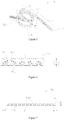
Figure 1 is a structural schematic diagram of an elastic coil in a prior art; -
Figure 2 is an operation schematic diagram of implantation of a bronchoscope and building of a channel through a core wire in a prior art; -
Figure 3 is a schematic diagram of delivery of an elastic coil in a prior art; -
Figure 4 is a schematic diagram of release of an elastic coil in a prior art; -
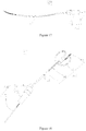
Figure 5 is a schematic diagram of an implant, on which part of a film is torn away, provided by one embodiment of the present disclosure; -
Figure 6 is a section view of part of the implant inFigure 5 ; -
Figure 7 is a section view of an elastic deformation section of the implant as shown inFigure 5 ; -
Figure 8 is a schematic diagram of a groove obtained by splitting and unfolding the elastic deformation section of the implant inFigure 5 along its lengthwise direction; -
Figure 9 is a schematic diagram of the implant without a film inFigure 5 ; -
Figure 10 is an enlarged view of a part inside a ring inFigure 9 ; -
Figure 11 is a schematic diagram of a connection section of the implant inFigure 5 ; -
Figure 12 is a schematic diagram of the connection section, which is split and unfolded along its lengthwise direction, inFigure 11 ; -
Figure 13 is a schematic diagram of a connection member of the implant inFigure 5 ; -
Figure 14 is a section view of the connection member inFigure 13 ; -
Figure 15 is a schematic diagram of deformation of the connection member inFigure 13 ; -
Figure 16 is a section view of the connection member inFigure 15 ; -
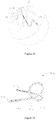
Figure 17 is a schematic diagram of a lung volume reduction device provided by one embodiment of the present disclosure; -
Figure 18 is a schematic diagram of decomposition of the lung volume reduction device inFigure 17 ; -
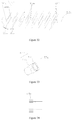
Figure 19 is a schematic diagram of a core wire of the lung volume reduction device inFigure 17 ; -
Figure 20 is an enlarged view of a portion M inFigure 19 ; -
Figure 21 is a schematic diagram of building of a working channel of a lung volume reduction device provided by one embodiment of the present disclosure; -
Figure 22 is an enlarged view of a portion L inFigure 21 ; -
Figure 23 is a schematic diagram of an implanted released; -
Figure 24 is an enlarged view of a portion O inFigure 23 ; -
Figure 25 is a schematic diagram of an implant provided by another embodiment of the present disclosure; -
Figure 26 is a schematic diagram of an elastic deformation section of the implant inFigure 25 ; -
Figure 27 is a schematic diagram of the elastic deformation section, which is split and unfolded along its lengthwise direction, inFigure 26 ; -
Figure 28 is a schematic diagram of a connection section of the implant inFigure 25 ; -
Figure 29 is a schematic diagram of the connection section, which is split and unfolded along its lengthwise direction, inFigure 28 ; -
Figure 30 is a schematic diagram of a connection subcomponent of the connection section inFigure 28 ; -
Figure 31 is a schematic diagram of a flexible guide section of the implant inFigure 25 ; -
Figure 32 is a schematic diagram of the flexible guide section, which is split and unfolded along its lengthwise direction, inFigure 31 ; -
Figure 33 is a schematic diagram of a connection member of the implant inFigure 25 ; -
Figure 34 is a section view of the connection member inFigure 33 ; -
Figure 35 is a top view of the proximal end side of the connection member inFigure 33 ; -
Figure 36 is a schematic diagram of an elastic implant provided by another embodiment; -
Figure 37 is a schematic diagram of a flexible guide section of the implant inFigure 36 ; -
Figure 38 is a schematic diagram of the flexible guide section, which is split and unfolded along its lengthwise direction, inFigure 37 ; -
Figure 39 is a schematic diagram of integration of an elastic deformation section, a flexible guide section and a connection section; -
Figure 40 is a schematic diagram of a connection member of the elastic implant inFigure 36 ; -
Figure 41 is a section view of the connection member inFigure 40 . - For the purpose of making objects, features and advantages of the present disclosure more clear, a detailed description for specific implementation modes of the present disclosure with drawings is as follows. Many specific details are specified in descriptions as follows to facilitate full understandings of the present disclosure. However, the present disclosure may be implemented through many other modes different from those described herein. A person skilled in the art can make similar improvements without departing from contents of the present disclosure, thus the present disclosure should not be limited by the specific embodiments disclosed as follows.
- In the field of intervention, generally, an end relatively close to an operator is called a proximal end, and an end relatively far away from the operator is called a distal end.
- Unless otherwise defined, all technical and scientific terms used herein have the same meanings of general understandings of persons skilled in the art of the present disclosure. Terms used in the description of the present disclosure herein are only intended to describe the specific embodiments, but not to limit the present disclosure. Terms "and/or" used herein include any and all combinations of one or multiple relevant listed items.
- With reference to
Figure 5 and Figure 6 , anelastic implant 500 provided by one embodiment of the present disclosure is of a tubular structure, which includes a hollow tubularelastic deformation section 51, aflexible guide section 53 connected with the distal end of theelastic deformation section 51, aconnection section 52 connected with the proximal end of theelastic deformation section 51, aconnection member 57 connected with the proximal end of theconnection section 52, and anelastic film 55. Theimplant 500 at least opens at the proximal end; theelastic deformation section 51 and theflexible guide section 53 may be of an integrated structure, or are fixedly connected with each other. The distal end of theflexible guide section 53 is the distal end of theelastic implant 500. Under the action of a same external force, theflexible guide section 53 deforms more easily than the elastic deformation section 51 (that is to say, under the action of a same external force, the bending resistance of theflexible guide section 53 is lower than that of the elastic deformation section 51), so that it may move in a bronchus better without injuring a surrounding tissue. - The
elastic deformation section 51 has a shape memory characteristic, and includes aproximal end 511 and adistal end 513 which are opposite; and thedistal end 513 is connected with theflexible guide section 53. Theelastic deformation section 51 further includesmultiple grooves 514 which are isolated from one another and are communicated with a lumen of theelastic deformation section 51. Themultiple grooves 514 enable theelastic deformation section 51 of theelastic implant 500 to be bent into a preset shape in a natural state, for example, a shape as shown inFigure 5 . - In the natural state (namely without any external force), the
elastic deformation section 51 is of a preset curled shape, but under the action of an external force, it may be restricted into a straight line form or any other shapes, and would be recovered into the preset shape through bending and twisting if the external force is withdrawn. Theelastic deformation section 51 may be made of any material which is commonly used in this industry and has a shape memory function. The present disclosure does not limit specific materials, and materials which are applicable to human body and have shape memory function are acceptable. In this embodiment, theelastic deformation section 51 is made of a nickel-titanium alloy. To be more specific, a machining method of anelastic deformation section 51 includes: firstly, cutting a section of hollow nickel-titanium tube having a diameter of about 0.5 to 2.0 mm and a wall thickness of 0.01 to 0.4 mm with laser; then bending the cut nickel-titanium tube with a die into a shape of anelastic deformation section 51 as shown inFigure 5 ; and finally, performing thermal treatment for modeling, thus obtaining theelastic deformation section 51. - With reference to
Figure 7 andFigure 8 together, in this embodiment, for the purpose that theelastic deformation section 51 may extend into a thinner bronchus to achieve a better squeezing effect on a corresponding tissue, preferably, theelastic deformation section 51 is made of a conical nickel-titanium tube having a consistent inner diameter and a gradually varying wall thickness, for example, a conical nickel-titanium tube having an inner diameter of 0.8 to 1.0 mm and a wall thickness varying from 0.01 mm at the distal end to 0.4 mm at the proximal end; multiple dumbbell-shapedgrooves 514 are formed in the nickel-titanium tube, and an extending direction 518 (namely an incision direction) of thesegrooves 514 and theaxial line 501 of theelastic deformation section 51 form a certain angle A which is preferably 10 to 90 degrees. Agap 508 of about 0.05 to 0.5 mm is reserved between every twoadjacent grooves 514. It should be understood that as theelastic deformation section 51 has themultiple grooves 514, its bending resistance may vary with changes of thelengths 510 of thegrooves 514 along their extendingdirection 518. A person skilled in the art could set thelengths 510 of thegrooves 514 of theelastic deformation section 51 in their extendingdirection 518 according to an actual requirement to achieve an aim that the bending resistance of theflexible guide section 53 is lower than that of theelastic deformation section 51. - With reference to
Figure 9 and Figure 10 together, theflexible guide section 53 is disposed at the distal end of theelastic deformation section 51, and is configured to play a guide role for theelastic deformation section 51, and under the action of the same external force, theflexible guide section 53 deforms easily in an increasing manner from the proximal end to the distal end. Theaxial line 503 at the distal end of theflexible guide section 53 and theaxial line 502 at thedistal end 511 of theelastic deformation section 51 form an included angle B which may be 5 to 60 degrees. In this embodiment, theflexible guide section 53 includes amain body portion 531, a flexible guidesection head end 533 disposed at the distal end of themain body portion 531 and aspring 535 disposed on the outer wall of themain body portion 531. - The
main body portion 531 may support thespring 535, and may be made of a metal with relatively high elasticity, such as a nickel-titanium alloy and a cobalt-chromium alloy, and the outer diameter of themain body portion 531 is gradually increased from the distal end of themain body portion 531 to the proximal end of themain body portion 531. The proximal end of themain body portion 531 is connected with thedistal end 511 of theelastic deformation section 51 in ways of macromolecular heat-shrink tube or film wrapping, glue adhesion, laser welding, soldering and the like. In this embodiment, themain body portion 531 is a solid nickel-titanium rod. It should be understood that themain body portion 531 also may be a hollow nickel-titanium tube. As a hollow nickel-titanium tube, if the inner diameter of themain body portion 531 does not change from the proximal end to the distal end, its outer diameter is gradually increased from the distal end to the proximal end, and if the outer diameter of themain body portion 531 does not change from the proximal end to the distal end, its inner diameter is gradually decreased from the distal end to the proximal end. - In this embodiment, the distal end of the
spring 535 and the distal end of themain body portion 531 are fused together at high temperature, thus forming the flexible guidesection head end 533. The flexible guidesection head end 533 is coaxial with the distal end of themain body portion 531 and closes the distal end of themain body portion 531. The flexible guidesection head end 533 may further have an imaging label (not shown in the figures). - The
spring 535 is formed by winding a metal wire with a diameter of 0.05 to 0.5 mm (preferably, a tungsten metal wire, a tantalum metal wire and the like with relatively high X-ray developing property). It should be understood that the flexible guidesection head end 533, thespring 535 and themain body portion 531 may be formed separately as well, and then the flexible guidesection head end 533, and the distal end of thespring 535 are connected together with the distal end of themain body portion 531 in ways of macromolecular heat-shrink tube or film wrapping, glue adhesion, laser welding and the like; in case of separate forming, preferably, the flexible guidesection head end 533 is made of a metal with relatively high X-ray developing property, such as tungsten and tantalum. It further should be understood that the flexible guidesection head end 533 may be removed as required. - It further should be understood that if there is no flexible guide
section head end 533, and themain body portion 531 is a hollow nickel-titanium tube, on one hand, a closing member made of the same material or a similar material as theguide head 533 may be disposed in the proximal end of themain body portion 531 to fully close or half close the distal end of theelastic deformation section 51; on the other hand, the proximal end of themain body portion 531 may be also communicated with theelastic deformation section 51; and at this moment, theimplant 500 opens at both the proximal end and the distal end. In any case, it only needs to ensure that a core wire (specifically described below) does not penetrate through the distal end of theflexible guide section 53, that is to say, when theimplant 500 opens at the distal end, it needs to ensure that the core wire may enter theimplant 500 and the outer diameter of the core wire would be larger than that of an incircle of the opening in the distal end of the implant 500 (when the opening is a non-circular opening, such as a triangular opening and a square opening) or larger than that of the opening in the distal end (when the opening is a circular opening). - With reference to
Figure 11 and Figure 12 together, theconnection section 52 is connected between theconnection member 57 and theelastic deformation section 51, and under the action of a same external force, the bending resistance of theconnection section 52 is lower than that of the elastic deformation section 51 (namely under the action of a same external force, theconnection section 52 deforms more easily than the elastic deformation section 51). In this embodiment,multiple groove groups 1702 are disposed on theconnection section 52. After theconnection section 52 is split along an axial direction and then flattened, it can be seen that eachgroove group 1702 includes threegrooves connection section 52 and are parallel to one another, and two ends of the three grooves are aligned with each other in the circumferential direction. And acertain gap 1703 is reserved between every two adjacent grooves in eachgroove group 1702, and agap 1704 is reserved between every twoadjacent groove groups 1702. Each groove is of a slender structure, and the extending direction AC of the multiple grooves and theaxial line 513 of theconnection section 52 form a certain included angle C. The bending resistance of thewhole connection section 52 may be adjusted by adjusting the number of the grooves in eachgroove group 1702, the sizes of thegaps 1703, the degree size of the included angle C between the extending direction AC of the grooves and theaxial line 501 of theelastic deformation section 51 and the size of thegap 1704 between every twoadjacent groove groups 1702, so that the bending resistance of theconnection section 52 is lower than that of theelastic deformation section 51. In other embodiments, there may be 2 to 6 grooves in eachgroove group 1702, thegap 1703 between every two adjacent grooves in eachgroove group 1702 may be 0.05 to 1 mm, the included angle C may be 10 to 85 degrees, and thegap 208 between every two adjacent groups may be 0.1 to 1.0 mm. The outer diameter of theelastic deformation section 51 is about 1.0 to 2.0 mm, and the wall thickness is 0.05 to 0.3 mm. Connection between theconnection section 52 and theelastic deformation section 51 may be realized in ways of macromolecular heat-shrink tube or film wrapping, glue adhesion, laser welding, soldering and the like. Based on prior arts, an integrated cutting way is preferred that is theelastic deformation section 51 and theconnection section 52 which have different texture features are cut from different regions on the same tube material. - With reference to
Figure 13 andFigure 14 together, theconnection member 57 is disposed at the proximal end of theconnection section 52, and includes aprotuberance 571 and aconnection portion 573. The outer diameter D of theprotuberance 571 is larger than that of a portion, which is close to theprotuberance 571, on theelastic implant 500 in a delivery state. In this implementation mode, the outer diameter of the portion, which is close to theprotuberance 571, on theelastic implant 500 is the outer diameter of the proximal end of theconnection section 52. Aninternal thread 574 is in theprotuberance 571. Theconnection portion 573 is disposed between theprotuberance 571 and theconnection section 52, and has acavity 575 which penetrates through the end surfaces of the proximal end and the distal end of theconnection portion 573. In this embodiment, the cross section, which is parallel to a longitudinal central axis of theprotuberance 571, of theprotuberance 571 includes two opposite semicircles, and the outer diameter D would not exceed 2.8 mm, preferably 2.0 to 2.3 mm. Theprotuberance 571 effectively enlarges a contact area of the proximal end of theelastic implant 500 and reduce the injury to a lung tissue due to the implantation of theelastic implant 500. It should be understood that the end surface of part of the distal end of theprotuberance 571 is sunken towards the proximal end of theprotuberance 571, thereby forming an annular recess 576 (seeFigure 15 and Figure 16 ) surrounding the longitudinal central line of theprotuberance 571 to provide a buckling position for biopsy forceps which may clamp a connection device more effectively to recycle theelastic implant 500. - With reference to
Figure 5 and Figure 6 together, theelastic implant film 55 completely wraps the outer surface of theelastic implant 500 except for theprotuberance 571, and eachgroove 514 is filled with the film, but the film does not block the lumen of theelastic implant 500, thereby ensuring that theelastic implant film 55 firmly wraps theelastic implant 500 and also ensuring that the lumen of theelastic implant 500 is unblocked. Theelastic implant film 55 may have a thickness of 0.01 to 0.8 mm, and may be prepared from macromolecular solutions featuring high chemical stability, water resistance and weather aging resistance, good low compressibility, good biocompatibility, high mechanical strength, non-toxicity, odorlessness and the like. For example, these macromolecular solutions may be silicone rubber or polyurethane solutions. As theelastic implant film 55 is combined with a metal matrix, the end portion of its proximal end would turn up and fall off most easily under an external force; the outer diameter of theprotuberance 571 is larger than that of the portion, which is close to theprotuberance 571, on theelastic implant 500 in the delivery state, so that theprotuberance 571 may protect the end portion of the proximal end of theelastic implant film 55 from being in contact with a tube wall in delivery and withdrawal processes, thereby protecting theelastic implant film 55 from turning up and falling off in the delivery and withdrawal processes. - With reference to
Figure 17 and Figure 18 together, a lungvolume reduction device 600 provided by one embodiment of the present disclosure includes anelastic implant 500 and adelivery device 700. Thedelivery device 700 includes acore wire 71 and a pushingmechanism 73. - The
core wire 71 is accommodated in a lumen of theelastic implant 500, and is configured to limit theelastic implant 500 in an approximately straight line type delivery state to facilitate delivery of theimplant 500 to a lesion portion, thus no delivery sheath is needed to restrict theimplant 500, which prevents the delivery sheath from injuring a trachea in a delivery process and further reduces incidence of pneumothorax. Thecore wire 71 may be made of a section of metal wire having a diameter of 0.1 to 1.1 mm. Compared with the prior art, the present disclosure does not need the delivery sheath, so that theimplant 500 may be implanted into a lung bypass or the ends of some small-diameter tracheas to achieve a better treatment effect. - With reference to
Figure 19 and Figure 20 together, for the purpose of safety and convenience in operation, it needs to dispose a flexible corewire guide head 75, which is coaxial with thecore wire 71 and has an imaging label, at the distal end of thecore wire 71. The outer diameter of the corewire guide head 75 is consistent with that of thecore wire 71. The corewire guide head 75 includes aguide post 751 and aspring 753 fixed outside theguide post 751 in a sleeving manner. Theguide post 751 and thecore wire 71 are of an integrated structure or theguide post 751 is fixedly connected to the distal end of thecore wire 71; and thespring 753 has an imaging label. - The core
wire guide head 75 is configured to guide thecore wire 71 to successfully enter the lumen of theelastic implant 500. The flexible corewire guide head 75 may be implemented through a flexible spring, and namely thespring 753 is disposed in a sleeving manner on theguide post 751 which is of an integrated structure with thecore wire 71 or is fixedly connected to the distal end of thecore wire 71. A specific manufacturing method may include: firstly thinning the head end of thecore wire 71 to manufacture theguide post 751, and then fixing a section of thespring 753 having a length of 5 to 150 mm outside theguide post 751. Thespring 753 and thecore wire 71 may be fixed in ways of macromolecular heat-shrink tube or film wrapping, glue adhesion, laser welding, soldering and the like. Under the guide of the flexible corewire guide head 75, thecore wire 71 may successfully enter the lumen of theimplant 500 from the proximal end of theimplant 500 to restrict theimplant 500 into an approximate straight line form (as shown inFigure 17 ) from the shape as shown inFigure 5 andFigure 9 . - In this embodiment, with the
flexible guide section 53, theimplant 500 equipped with acore wire 71 further has a function of exploring a path in the bronchus to reach the lesion region. It needs to dispose the imaging label on the corewire guide head 75 to guide and monitor an operation condition of thecore wire 71 in the lung. The imaging label can display the implant through a fluorescence inspection system, an ultrasonic imaging system, an MRI (Magnetic Resonance Imaging) system, an X-ray CT (Computerized Tomography) system or other remote imaging systems, and there is no limitation to a specific structure. The core wire 101 is developed and guided through these systems. In this embodiment, the spring formed by winding a metal wire with the wire diameter of 0.01 to 0.3 mm and relatively high X-ray developing property, such as a tungsten metal wire and a tantalum metal wire, is used as an imaging label. In this embodiment, the imaging label and the corewire guide head 75 are combined into one component to realize two functions. Besides such a mode, an extra developing label may be disposed on the corewire guide head 75. Of course, when the surface of the implant of the present disclosure is not wrapped by an elastic film, and the implant is made of a material capable of realizing imaging by itself, such as the nickel-titanium alloy, no imaging label is disposed. - The pushing
mechanism 73 includes a hollow pushingmember 731 and acontrol handle 733 connected with the hollow pushingmember 731. The hollow pushingmember 731 and theimplant 500 are disposed on thecore wire 71 in a sleeving manner in sequence from outside to inside; and the distal end of the hollow pushingmember 731 is detachably connected with theproximal end 511 of theimplant 500. In this embodiment, the hollow pushingmember 731 is a pushing steel cable, and aconnection matching member 735 having an external thread matched with the internal thread of theconnection member 57 is disposed at its distal end. During assembling, the internal thread of theconnection member 57 is in threaded connection with theconnection matching member 735 with the external thread of the pushingmechanism 73, and theimplant 500 may be reliably fixed at the distal end of the hollow pushingmember 73. After animplant 500 is pushed to a corresponding position of the bronchus, theconnection member 57 of theimplant 500 is screwed out of and separated from theconnection matching member 735 of the hollow pushingmember 73 by twisting the control handle 733 of the hollow pushingmember 73. Theconnection member 57 and theconnection matching member 735 may be other detachably fixed connection components, such as magnetic connection devices, elastic buckles and ropes, which are disposed on theimplant 500 and the hollow pushing member 103 respectively to realize detachable connection. - Assembling steps of the
elastic implant 500 and thecore wire 71 as well as the hollow pushingmember 731 are as follows: firstly, connecting theelastic implant 500 with theconnection matching member 735 at the distal end of the hollow pushingmember 731 through the threads to communicate the hollow pushingmember 731 with an inner channel of theelastic implant 500; and then pushing thecore wire 71 into theelastic implant 500 along a channel of the hollow pushingmember 731 to restrict theelastic implant 500, which is curled in a natural state, into a tube in an approximately straight line type delivery state. - With reference to figures from
Figure 21 to Figure 24 , animplant 500 equipped with thecore wire 73 and the hollow pushingmember 731 is delivered into thebronchus 1504 of alung 1503 through a workingchannel 1502 of abronchoscope 1501. With the assistance of X-rays, theimplant 500 is pushed to an expected position by using the hollow pushingmember 731, and then thecore wire 71 is withdrawn. During withdrawal of thecore wire 71, theimplant 500 is automatically recovered to the natural shape as shown inFigure 17 from the straight line type delivery state restricted by thecore wire 71; and in this recovery process, the pulmonary emphysema region may be squeezed and pulled, and a relatively healthy lung tissue therearound may better exert a respiration physiological function, thereby achieving a lung volume reduction effect. The threaded connection between theconnection matching member 735 at the distal end of the hollow pushingmember 731 and theconnection member 57 of theelastic implant 500 is relieved by rotating thehandle 733, thereby releasing theimplant 500. - With reference to
Figure 25 , anelastic implant 500a provided by another embodiment of the present disclosure includes a hollow tubularelastic deformation section 51 a, a flexible guide section 53a connected with the distal end of theelastic deformation section 51a, aconnection section 52a connected with the proximal end of theelastic deformation section 51a, and aconnection member 57a connected with the proximal end of the connection section 54a. Theimplant 500a at least opens at the proximal end, and theelastic deformation section 51a and the flexible guide section 53a may be of an integrated structure, or are fixedly connected with each other. The distal end of the flexible guide section 53a is the distal end of theelastic implant 500a. Under the action of a same external force, the flexible guide section 53a deforms more easily than theelastic deformation section 51a (that is to say, under the action of the same external force, the bending resistance of the flexible guide section 53a is lower than that of theelastic deformation section 51a), so that it may move in a bronchus better without injuring a surrounding tissue. - With reference to
Figure 26 and Figure 27 together, theelastic deformation section 51a includesmultiple groove clusters 1802 which are arrayed in an axial direction of theelastic deformation section 51a in a spacing manner. Eachgroove cluster 1802 consists of fiveelliptical groove groups 1803 which are disposed side by side and are arrayed in a stair-stepping manner. Eachgroove group 1803 in this embodiment consists of two side-by-side grooves; acertain gap 1801 is reserved between the two grooves in eachgroove group 1803; and the long axis of each groove is perpendicular to the axial line of theelastic deformation section 51a. The extendingdirection 1805 of arrangement of every two groups in eachgroove cluster 1802 and theaxial line 501a of theelastic deformation section 51a form a certain included angle E which may be 60 to 90 degrees. Agap 508a of about 0.3 to 5 mm is reserved between every twoadjacent groove groups 1803 in eachgroove cluster 1802. Thegroove groups 1803 arrayed in the stair-stepping manner contribute to bending theelastic deformation section 51a into a specific shape. A portion having a length of about 0.5 to 5 mm at the proximal end 511a of theelastic deformation section 51a is cut into a threaded trench serving as aconnection member 57a. A cut nickel-titanium tube is bent with a die into a shape as shown inFigure 25 , and then is subjected to thermal treatment modeling, thereby forming theelastic deformation section 51a of anelastic implant 500a. - Under the action of the same external force, the bending resistance of the
connection section 52a is lower than that of theelastic deformation section 51a to reduce injury of theconnection section 52a to a bronchus wall better. With reference to Figures fromFigure 28 to Figure 30 , in this embodiment, theconnection section 52a is a tubular body which is formed by connecting multiplehollow subcomponents 2004 in an end-to-end manner and has multiple circumferentially continuouswavy grooves 2001. Thegrooves 2001 havecertain widths 2005 which may be preferably 0.01 mm to 0.3 mm. Starting points and ending points of every two adjacentwavy grooves 2001 are overlapped in the circumferential direction of theconnection section 52a. Preferably, in this embodiment, the proximal end of eachsubcomponent 2004 includes multiple proximal end bulges 2002 distributed in the circumferential direction of thehollow subcomponent 2004 in an equal spacing manner; and the circumferential length of eachproximal end bulge 2002 is gradually decreased from the proximal end to the distal end, thus a dovetail-shaped opening towards aproximal end recess 2006 at the proximal end is formed between every two adjacent proximal end bulges 2002; the distal end of eachhollow subcomponent 2004 includes multiple distal end bulges 2007 distributed in the circumferential direction of thehollow subcomponent 2004 in an equal spacing manner; and the circumferential length of eachdistal end bulge 2007 is gradually increased from the proximal end to the distal end, thus a dovetail-shaped opening towards adistal end recess 2008 at the distal end is formed between every two adjacent distal end bulges 2007; the quantity of the proximal end bulges 2002 of eachhollow subcomponent 2004 is equal to that of the distal end bulges 2007 of the samehollow subcomponent 2004; and onedistal end recess 2008 on eachhollow subcomponent 2004 is aligned with oneproximal end bulge 2002 on the samehollow subcomponent 2004. Therefore, in twohollow subcomponents 2004, the multiple dovetail-shaped proximal end bulges 2002 on onehollow subcomponent 2004 mesh with the multipledistal end recesses 2008 of the otherhollow subcomponent 2004, so that the two separatedhollow subcomponents 2004 form an interlocked structure, and the multiplehollow subcomponents 2004 are spliced and combined to form theconnection section 52a. As all the separatedsubcomponents 2004 are connected through meshing structures of the dovetail-shaped bulges and the dovetail recesses, theconnection section 52a with such structure has extremely high flexibility and connection strength, and may transmit a torque to theelastic deformation section 51a at a ratio of 1 to 1 during twisting of theconnection member 57. Based on prior arts, thesubcomponents 2004 may be also machined in other ways, such as machining, casting and powder metallurgy. It should be understood that theconnection section 52a has extremely high flexibility and extremely low bending resistance, so that the aim that the bending resistance of theconnection section 52a is lower than that of theelastic deformation section 51a may be achieved easily by adjusting the bending resistance of theelastic deformation section 51a. It should be understood that the multiple proximal end bulges 2002 may be also distributed at the proximal ends of thesubcomponents 2004 in a non-equal spacing manner to achieve the aim that themultiple subcomponents 2004 may be spliced together. - Under the action of the same external force, the bending resistance of the flexible guide section 53a is lower than that of the
elastic deformation section 51a, so as to guide theelastic deformation section 51a better to move in the bronchus and reduce injury to the bronchus wall. Under the action of the same external force, the bending resistance of the flexible guide section 53a is gradually enhanced from the distal end to the proximal end. With reference toFigure 31 andFigure 32 together, in this embodiment, the flexible guide section 53a is a tubular body, which is cut from a nickel-titanium tube through laser and has grooves, and under the action of the same external force, its bending resistance is gradually enhanced from the distal end to the proximal end (that is to say, under the action of the same external force, its deformability is gradually lowered from the distal end to the proximal end, and namely it becomes harder and harder from the distal end to the proximal end), so as to achieve a better guide effect on theelastic implant 500a. It should be understood that as the flexible guide section 53a is the tubular body having the multiple grooves, its bending resistance may change with the change of a gap between every two adjacent grooves. A person skilled in the art could set the gap between every two adjacent grooves according to an actual requirement to achieve an aim that the bending resistance of the flexible guide section 53a is lower than that of theelastic deformation section 51a. - The flexible guide section 53a includes multiple slender groove groups from 1601 to 1608. Each groove group (for example 1601) consists of two or more
parallel grooves certain width 1609. The extending direction of these groove groups from 1601 to 1608 and the axial line 513a of the flexible guide section 53a form a certain angleF. A gap 1610 is reserved between every two adjacent groove groups. The bending resistance of the flexible guide section 53a may be adjusted by adjusting the number and thewidths 1609 of the grooves in each groove group, the degree size of the angle F and the sizes of thegaps 1610. Preferably, there are 2 to 6parallel grooves 1601, thegaps 1609 are 0.05 to 1 mm, the angle F is 5 to 85 degrees, and thegaps 1610 is 0.1 to 1.0 mm. The parallel groove groups (from 1601 to 1608) withdifferent widths 1609 are combined into a same nickel-titanium tube, thereby achieving the aim that under the action of the same external force, the bending resistance of the flexible guide section 53a is gradually enhanced from the distal end to the proximal end; and the flexible guide section 53a with a bending resistance gradual change effect may achieve a better guide effect on theelastic implant 500a. - The flexible guide section 53a and the
elastic deformation section 51a may be connected in ways of macromolecular heat-shrink tube or film wrapping, glue adhesion, laser welding, soldering and the like. Based on the prior art, an integrated cutting way is preferred: cutting the flexible guide section 53a and theelastic deformation section 51a which have different texture features from different regions on the same tube material. For the purpose of achieving a bending resistance gradual change effect on the flexible guide section 53a, one feasible mode is to keep the angle F between every two adjacent groove groups unchanged and gradually decrease thewidths 1609 of the grooves from the distal end to the proximal end, and another feasible mode is to keep thewidths 1609 of the grooves in every two adjacent groove groups unchanged and gradually enlarge the angle F. It should be understood that the effect of gradually enhancing the bending resistance of the flexible guide section 53a from the distal end to the proximal end also may be achieved by simultaneously changing the angle F and thewidths 1609 of the grooves in every two adjacent groove groups. - With reference to
Figure 33 and Figure 34 , theconnection member 57a is substantially the same as theconnection body 57, but what is different is that aprotuberance 571a of theconnection member 57a has multiplesmall bulges 578 which are distributed in the circumferential direction of theprotuberance 571a in an equal spacing manner and are connected with one another. With reference toFigure 35 , the multiplesmall bulges 578 form avirtual circumference 579 together (namely an circumcircle of the multiplesmall bulges 578 is 579). The diameter of thecircumference 579 is the outer diameter of theprotuberance 571 a. The multiplesmall bulges 578 provide a buckling position for biopsy forceps, so that the biopsy forceps may effectively clamp the connection device to recycle theelastic implant 500a. Theconnection member 57a and theconnection section 52a may be connected in ways of macromolecular heat-shrink tube or film wrapping, glue adhesion, laser welding, soldering and the like. - With reference to
Figure 36 , anelastic implant 500b provided by another embodiment of the present disclosure includes a hollow tubularelastic deformation section 51b, aflexible guide section 53b connected with the distal end of theelastic deformation section 51b, aconnection section 52b connected with the proximal end of theelastic deformation section 51b, and aconnection member 57b connected with the proximal end of theconnection section 52b. Theimplant 500b at least opens at the proximal end; theelastic deformation section 51b and theflexible guide section 53b may be of an integrated structure, or are fixedly connected with each other. The distal end of theflexible guide section 53b is the distal end of theelastic implant 500b. Under the action of a same external force, theflexible guide section 53b deforms more easily than theelastic deformation section 51b, so that it may move in a bronchus better without injuring a surrounding tissue. - The arrangement mode of grooves of the
elastic deformation section 51b is substantially the same as that of the grooves of theconnection section 52 of the embodiment I, and no repeated descriptions will be given here. - With reference to
Figure 37 andFigure 38 , theflexible guide section 53b is a tubular body which is cut from a nickel-titanium tube through laser and has continuous spiral grooves, and under the action of the same external force, its bending resistance is gradually enhanced from the distal end to the proximal end (that is to say, under the action of the same external force, its deformability is gradually lowered from the distal end to the proximal end) to achieve a better guide effect on theelastic implant 500b. It should be understood that as theflexible guide section 53b is a tubular body having continuous spiral grooves, its bending resistance may change with the change of a gap between every two adjacent grooves. A person skilled in the art could set the gap between every two adjacent grooves according to an actual requirement to achieve an aim that the bending resistance of theflexible guide section 53b is lower than that of theelastic deformation section 51b. - The
flexible guide section 53b includes thecontinuous spiral grooves 2502. On an unfolded plane formed by splitting theflexible guide section 53b along its axial direction, from the distal end to the proximal end of theflexible guide section 53b, the gap between every twoadjacent grooves 2502 is gradually increased as well to achieve the aim of gradually enhancing the bending resistance of theflexible guide section 53b from the distal end to the proximal end. - It should be understood that on the unfolded plane formed by splitting the
flexible guide section 53b along its axial direction, from the distal end to the proximal end of theflexible guide section 53b, when an included angle G between the extendingdirection 2505 of thegrooves 2502 of theflexible guide section 53b and theaxial direction 2504 of theflexible guide section 53b is unchanged, and the widths of the grooves of theflexible guide section 53b along theaxial direction 2504 of theflexible guide section 53b are gradually decreased, the gap between every twoadjacent grooves 2502 is gradually increased as well, and the aim of gradually enhancing the bending resistance of theflexible guide section 53b from the distal end to the proximal end may be also achieved. - It should be understood that on the unfolded plane formed by splitting the
flexible guide section 53b along its axial direction, from the distal end to the proximal end of theflexible guide section 53b, when the widths of the grooves of theflexible guide section 53b along theaxial direction 2504 of theflexible guide section 53b are unchanged, and the included acute angle between the extendingdirection 2505 of the grooves of theflexible guide section 53b and theaxial direction 2504 of theflexible guide section 53b is gradually enlarged, the gap between every twoadjacent grooves 2502 is gradually increased as well, and the aim of gradually enhancing the bending resistance of theflexible guide section 53b from the distal end to the proximal end may be also achieved. - The structure of the
connection section 52b is substantially the same as that of theconnection section 52a, and no repeated descriptions will be given here. - Preferably, an integrated forming way is adopted. Features of the
elastic deformation section 51b, theflexible guide section 53b and theconnection section 52b which are cut from the same nickel-titanium tube through laser are as shown inFigure 39 , and problems of low connection strength and the like which are caused by a connection mode may be effectively avoided. - With reference to
Figure 40 andFigure 41 together, theconnection member 57b is substantially the same as theconnection member 57, but what is different is that part of the side surface of theprotuberance 571 b of theconnection member 57b is sunken towards the inside of theprotuberance 571b, thereby forming anannular recess 577 surrounding the longitudinal central line of theprotuberance 571b. - The above descriptions are made to the embodiments of the present disclosure in combination of drawings, but not intended to limit the present disclosure by the above-mentioned specific implementation modes which are merely schematic, but not restrictive. An ordinary person skilled in the art can also make many implementation modes without departing from the purpose of the present disclosure and the scope claimed by claims under an enlightenment of the present disclosure, and these implementation modes shall all fall within the protection of the present disclosure.
Claims (19)
- A lung volume reduction elastic implant, characterized in that the implant is tubular, at least opens at the proximal end, and comprises an elastic deformation section, a flexible guide section connected with the distal end of the elastic deformation section, and a protuberance connected with the proximal end of the elastic deformation section; and the elastic deformation section has a shape memory characteristic and has a plurality of grooves formed in a spacing manner along a lengthwise direction of the elastic deformation section; and each groove is communicated with a lumen of the elastic deformation section; and under the action of a same external force, the flexible guide section deforms more easily than the elastic deformation section, and the outer diameter of the protuberance is larger than that of a portion, which is close to the protuberance, on the elastic implant in a delivery state.
- The lung volume reduction elastic implant according to claim 1, characterized in that an included angle between the incision direction of each groove and the lengthwise direction of the elastic deformation section ranges from 10 to 90 degrees.
- The lung volume reduction elastic implant according to claim 2, characterized by further comprising an elastic film at least wrapping the outer walls of the elastic deformation section and the flexible guide section.
- The lung volume reduction elastic implant according to claim 3, characterized in that the grooves are further filled with the elastic film.
- The lung volume reduction elastic implant according to claim 2, characterized in that the elastic deformation section is made of a conical nickel-titanium tube having an outer diameter gradually increased from the distal end to the proximal end, and a gap of 0.05 mm to 0.5 mm is reserved between every two adjacent grooves of the elastic deformation section.
- The lung volume reduction elastic implant according to claim 1, characterized in that under the action of a same external force, the flexible guide section deforms easily in an increasing manner from the proximal end to the distal end.
- The lung volume reduction elastic implant according to claim 6, characterized in that the flexible guide section comprises a main body portion having a spring on the outer wall; the proximal end of the main body portion is connected with the elastic deformation section; and the outer diameter of the main body portion is gradually increased from the distal end to the proximal end.
- The lung volume reduction elastic implant according to claim 6, characterized in that the flexible guide section comprises a tubular body which is cut from the nickel-titanium tube and has continuous spiral grooves.
- The lung volume reduction elastic implant according to claim 8, characterized in that the gap between every two adjacent grooves of the flexible guide section along the axial direction of the flexible guide section is gradually increased from the distal end to the proximal end of the flexible guide section.
- The lung volume reduction elastic implant according to claim 1, characterized by further comprising a connection section located between the elastic deformation section and the protuberance, wherein under the action of a same external force, the connection section deforms more easily than the elastic deformation section.
- The lung volume reduction elastic implant according to claim 10, characterized in that the connection section has a plurality of grooves formed in a spacing manner along the lengthwise direction of the connection section, and each groove of the connection section is communicated with the lumen of the connection section.
- The lung volume reduction elastic implant according to claim 10, characterized in that the connection section comprises multiple hollow subcomponents connected with one another in an end-to-end manner; the proximal end of each hollow subcomponent comprises multiple proximal end bulges distributed along a circumferential direction of the hollow subcomponent; the circumferential length of each proximal end bulge from the proximal end to the distal end is gradually decreased; a proximal end recess is formed between every two adjacent proximal end bulges; the distal end of each hollow subcomponent comprises multiple distal end bulges distributed along the circumferential direction of the hollow subcomponent; the circumferential length of each distal end bulge from the proximal end to the distal end is gradually increased; and a distal end recess is formed between every two adjacent distal end bulges.
- The lung volume reduction elastic implant according to claim 1, characterized in that the end surface of part of the distal end of the protuberance is sunken towards the proximal end of the protuberance, thereby forming an annular recess surrounding the longitudinal central line of the protuberance.
- The lung volume reduction elastic implant according to claim 1, characterized in that part of the side surface of the protuberance is sunken towards the inside of the protuberance, thereby forming an annular recess surrounding the longitudinal central line of the protuberance.
- The lung volume reduction elastic implant according to claim 1, characterized in that the protuberance comprises multiple small bulges distributed along the circumferential direction of the protuberance in a spacing manner.
- A lung volume reduction device, characterized by comprising any one of the implants according to claims 1 to 15, and a delivery device matched with the implant, wherein the delivery device comprises a core wire and a hollow pushing member; the proximal end of the implant is detachably connected to the distal end of the pushing member; and the core wire is movably disposed in a lumen of the implant and a lumen of the pushing member in a penetrating manner.
- The lung volume reduction device according to claim 16, characterized in that a core wire guide head coaxial with the core wire is disposed at the distal end of the core wire, and the outer diameter of the core wire guide head is consistent with that of the core wire.
- The lung volume reduction device according to claim 17, characterized in that the core wire guide head comprises a guide post and a spring disposed on the guide post in a sleeving manner; the guide post and the core wire are of an integrated structure or the guide post is fixedly connected to the distal end of the core wire; and the spring has an imaging label.
- The lung volume reduction device according to claim 16, characterized in that the proximal end of the implant is detachably connected with the distal end of the pushing member.
Applications Claiming Priority (2)
| Application Number | Priority Date | Filing Date | Title |
|---|---|---|---|
| CN201510785463.8A CN106691626B (en) | 2015-11-16 | 2015-11-16 | Lung volume reduction elasticity implant and lung volume reduction instrument |
| PCT/CN2016/087790 WO2017084347A1 (en) | 2015-11-16 | 2016-06-29 | Lung volume reduction elastic implant and lung volume reduction device |
Publications (3)
| Publication Number | Publication Date |
|---|---|
| EP3378447A1 true EP3378447A1 (en) | 2018-09-26 |
| EP3378447A4 EP3378447A4 (en) | 2019-07-31 |
| EP3378447B1 EP3378447B1 (en) | 2025-03-12 |
Family
ID=58717359
Family Applications (1)
| Application Number | Title | Priority Date | Filing Date |
|---|---|---|---|
| EP16865527.2A Active EP3378447B1 (en) | 2015-11-16 | 2016-06-29 | Lung volume reduction elastic implant and lung volume reduction device |
Country Status (5)
| Country | Link |
|---|---|
| US (1) | US10687821B2 (en) |
| EP (1) | EP3378447B1 (en) |
| CN (1) | CN106691626B (en) |
| ES (1) | ES3025735T3 (en) |
| WO (1) | WO2017084347A1 (en) |
Families Citing this family (12)
| Publication number | Priority date | Publication date | Assignee | Title |
|---|---|---|---|---|
| CN108272538B (en) | 2016-12-30 | 2020-06-12 | 先健科技(深圳)有限公司 | Elastic implant for lung volume reduction and lung volume reduction instrument |
| US11172933B2 (en) * | 2017-08-29 | 2021-11-16 | Covidien Lp | Methods and devices for altering lung volume |
| CN109966011B (en) * | 2017-12-28 | 2021-08-17 | 深圳市先健呼吸科技有限公司 | Delivery and retrieval device and system for an implant having at least one cavity |
| CN109965923B (en) * | 2017-12-28 | 2021-07-06 | 深圳市先健呼吸科技有限公司 | Delivery device for an implant with at least one cavity |
| CN109984876B (en) * | 2017-12-29 | 2021-10-22 | 深圳市先健呼吸科技有限公司 | Retrieval system and sheath for a lung volume reduction implant |
| CN110638488B (en) * | 2018-06-26 | 2025-08-15 | 杭州唯强医疗科技有限公司 | Implant pushing device with reliable connection and implant conveying system |
| CN110638490B (en) * | 2018-06-26 | 2025-08-15 | 杭州唯强医疗科技有限公司 | Lockable implant pushing device and implant delivery system |
| CN113107938B (en) * | 2021-04-02 | 2022-05-06 | 桂林理工大学 | A bendable sleeve and retractable structure |
| CN116421398A (en) * | 2023-04-27 | 2023-07-14 | 花沐医疗科技(上海)有限公司 | A tear plug insertion device |
| CN118476900B (en) * | 2024-04-03 | 2026-03-20 | 汉星医疗科技(深圳)有限公司 | Implant, delivery mechanism, lung volume reduction implantation device and system |
| CN118203400B (en) * | 2024-05-20 | 2024-08-02 | 四川大学华西医院 | Traction resetting device |
| CN120732489B (en) * | 2025-09-04 | 2026-01-06 | 北京大学 | An adjustable medical device |
Family Cites Families (13)
| Publication number | Priority date | Publication date | Assignee | Title |
|---|---|---|---|---|
| ES2339029T3 (en) * | 1995-06-07 | 2010-05-14 | Conceptus, Inc. | CATHETER SYSTEM FOR EXPANDABLE TRANSCERVIC ANTICONCEPTIVE DEVICES OF FALOPIO TUBE WITH MECHANICAL FIXING TO THE FALOPIO TUBE. |
| US8157837B2 (en) * | 2006-03-13 | 2012-04-17 | Pneumrx, Inc. | Minimally invasive lung volume reduction device and method |
| US9402633B2 (en) * | 2006-03-13 | 2016-08-02 | Pneumrx, Inc. | Torque alleviating intra-airway lung volume reduction compressive implant structures |
| US8632605B2 (en) * | 2008-09-12 | 2014-01-21 | Pneumrx, Inc. | Elongated lung volume reduction devices, methods, and systems |
| US11291503B2 (en) * | 2008-10-21 | 2022-04-05 | Microcube, Llc | Microwave treatment devices and methods |
| US20140358140A1 (en) * | 2008-10-21 | 2014-12-04 | Microcube, Llc | Microwave treatment devices and methods |
| JP5809621B2 (en) * | 2009-05-18 | 2015-11-11 | ヌームアールエックス・インコーポレーテッド | Implants for treating a patient's lungs |
| CN202010169U (en) * | 2011-03-31 | 2011-10-19 | 王涛 | Novel memory elastic coil for reducing lung volumes |
| CN103860299A (en) * | 2012-12-14 | 2014-06-18 | 常州乐奥医疗科技有限公司 | Anatomical lung volume reduction elastic bracket |
| SG10201709395QA (en) * | 2013-03-15 | 2017-12-28 | Pneumrx Inc | Torque alleviating intra-airway lung volume reduction compressive implant structures |
| CN105455930B (en) * | 2014-06-11 | 2019-08-16 | 先健科技(深圳)有限公司 | Lung volume reduction elasticity implant and instrument |
| AU2015290043B2 (en) * | 2014-07-18 | 2019-08-22 | Ethicon, Inc. | Methods and devices for controlling the size of emphysematous bullae |
| CN106580527B (en) * | 2015-10-15 | 2019-02-12 | 先健科技(深圳)有限公司 | Lung volume reduction elastic implant and lung volume reduction device |
-
2015
- 2015-11-16 CN CN201510785463.8A patent/CN106691626B/en active Active
-
2016
- 2016-06-29 US US15/776,050 patent/US10687821B2/en active Active
- 2016-06-29 WO PCT/CN2016/087790 patent/WO2017084347A1/en not_active Ceased
- 2016-06-29 ES ES16865527T patent/ES3025735T3/en active Active
- 2016-06-29 EP EP16865527.2A patent/EP3378447B1/en active Active
Also Published As
| Publication number | Publication date |
|---|---|
| US20180333157A1 (en) | 2018-11-22 |
| EP3378447B1 (en) | 2025-03-12 |
| US10687821B2 (en) | 2020-06-23 |
| ES3025735T3 (en) | 2025-06-09 |
| CN106691626A (en) | 2017-05-24 |
| CN106691626B (en) | 2019-03-08 |
| EP3378447A4 (en) | 2019-07-31 |
| WO2017084347A1 (en) | 2017-05-26 |
Similar Documents
| Publication | Publication Date | Title |
|---|---|---|
| EP3378447B1 (en) | Lung volume reduction elastic implant and lung volume reduction device | |
| EP3363408B1 (en) | Lung-volume-reduction elastic implant and lung-volume-reduction instrument | |
| CN105455930B (en) | Lung volume reduction elasticity implant and instrument | |
| AU2014233907B2 (en) | Torque alleviating intra-airway lung volume reduction compressive implant structures | |
| EP3563801B1 (en) | Lung volume reduction elastic implant and lung volume reduction instrument | |
| US20190321050A1 (en) | Methods and devices for the treatment of pulmonary disorders | |
| US11291457B2 (en) | Lung volume-reducing elastic implant and instrument | |
| EP3556325B1 (en) | Implant | |
| CN118476900B (en) | Implant, delivery mechanism, lung volume reduction implantation device and system | |
| KR20190059921A (en) | Guide wire | |
| CN110742667B (en) | Methods and devices for treating pulmonary dysfunction using implantable valves | |
| US20230240870A1 (en) | Launcher for Introduction of A Medical Device | |
| WO2019140179A1 (en) | Methods and devices for the treatment of pulmonary disorders |
Legal Events
| Date | Code | Title | Description |
|---|---|---|---|
| STAA | Information on the status of an ep patent application or granted ep patent |
Free format text: STATUS: THE INTERNATIONAL PUBLICATION HAS BEEN MADE |
|
| PUAI | Public reference made under article 153(3) epc to a published international application that has entered the european phase |
Free format text: ORIGINAL CODE: 0009012 |
|
| STAA | Information on the status of an ep patent application or granted ep patent |
Free format text: STATUS: REQUEST FOR EXAMINATION WAS MADE |
|
| 17P | Request for examination filed |
Effective date: 20180611 |
|
| AK | Designated contracting states |
Kind code of ref document: A1 Designated state(s): AL AT BE BG CH CY CZ DE DK EE ES FI FR GB GR HR HU IE IS IT LI LT LU LV MC MK MT NL NO PL PT RO RS SE SI SK SM TR |
|
| AX | Request for extension of the european patent |
Extension state: BA ME |
|
| DAV | Request for validation of the european patent (deleted) | ||
| DAX | Request for extension of the european patent (deleted) | ||
| A4 | Supplementary search report drawn up and despatched |
Effective date: 20190702 |
|
| RIC1 | Information provided on ipc code assigned before grant |
Ipc: A61F 2/04 20130101ALI20190626BHEP Ipc: A61F 2/95 20130101ALI20190626BHEP Ipc: A61B 17/12 20060101ALI20190626BHEP Ipc: A61F 2/82 20130101AFI20190626BHEP |
|
| STAA | Information on the status of an ep patent application or granted ep patent |
Free format text: STATUS: EXAMINATION IS IN PROGRESS |
|
| 17Q | First examination report despatched |
Effective date: 20200702 |
|
| RAP1 | Party data changed (applicant data changed or rights of an application transferred) |
Owner name: SHENZHEN LIFETECH RESPIRATION SCIENTIFIC CO., LTD. |
|
| GRAP | Despatch of communication of intention to grant a patent |
Free format text: ORIGINAL CODE: EPIDOSNIGR1 |
|
| STAA | Information on the status of an ep patent application or granted ep patent |
Free format text: STATUS: GRANT OF PATENT IS INTENDED |
|
| INTG | Intention to grant announced |
Effective date: 20241017 |
|
| P01 | Opt-out of the competence of the unified patent court (upc) registered |
Free format text: CASE NUMBER: APP_61957/2024 Effective date: 20241120 |
|
| GRAS | Grant fee paid |
Free format text: ORIGINAL CODE: EPIDOSNIGR3 |
|
| GRAA | (expected) grant |
Free format text: ORIGINAL CODE: 0009210 |
|
| STAA | Information on the status of an ep patent application or granted ep patent |
Free format text: STATUS: THE PATENT HAS BEEN GRANTED |
|
| AK | Designated contracting states |
Kind code of ref document: B1 Designated state(s): AL AT BE BG CH CY CZ DE DK EE ES FI FR GB GR HR HU IE IS IT LI LT LU LV MC MK MT NL NO PL PT RO RS SE SI SK SM TR |
|
| REG | Reference to a national code |
Ref country code: GB Ref legal event code: FG4D |
|
| REG | Reference to a national code |
Ref country code: CH Ref legal event code: EP |
|
| REG | Reference to a national code |
Ref country code: DE Ref legal event code: R096 Ref document number: 602016091553 Country of ref document: DE |
|
| REG | Reference to a national code |
Ref country code: IE Ref legal event code: FG4D |
|
| REG | Reference to a national code |
Ref country code: ES Ref legal event code: FG2A Ref document number: 3025735 Country of ref document: ES Kind code of ref document: T3 Effective date: 20250609 |
|
| PG25 | Lapsed in a contracting state [announced via postgrant information from national office to epo] |
Ref country code: RS Free format text: LAPSE BECAUSE OF FAILURE TO SUBMIT A TRANSLATION OF THE DESCRIPTION OR TO PAY THE FEE WITHIN THE PRESCRIBED TIME-LIMIT Effective date: 20250612 |
|
| PG25 | Lapsed in a contracting state [announced via postgrant information from national office to epo] |
Ref country code: FI Free format text: LAPSE BECAUSE OF FAILURE TO SUBMIT A TRANSLATION OF THE DESCRIPTION OR TO PAY THE FEE WITHIN THE PRESCRIBED TIME-LIMIT Effective date: 20250312 |
|
| PGFP | Annual fee paid to national office [announced via postgrant information from national office to epo] |
Ref country code: DE Payment date: 20250603 Year of fee payment: 10 |
|
| REG | Reference to a national code |
Ref country code: LT Ref legal event code: MG9D |
|
| PG25 | Lapsed in a contracting state [announced via postgrant information from national office to epo] |
Ref country code: NO Free format text: LAPSE BECAUSE OF FAILURE TO SUBMIT A TRANSLATION OF THE DESCRIPTION OR TO PAY THE FEE WITHIN THE PRESCRIBED TIME-LIMIT Effective date: 20250612 |
|
| PG25 | Lapsed in a contracting state [announced via postgrant information from national office to epo] |
Ref country code: HR Free format text: LAPSE BECAUSE OF FAILURE TO SUBMIT A TRANSLATION OF THE DESCRIPTION OR TO PAY THE FEE WITHIN THE PRESCRIBED TIME-LIMIT Effective date: 20250312 |
|
| REG | Reference to a national code |
Ref country code: NL Ref legal event code: MP Effective date: 20250312 |
|
| PG25 | Lapsed in a contracting state [announced via postgrant information from national office to epo] |
Ref country code: LV Free format text: LAPSE BECAUSE OF FAILURE TO SUBMIT A TRANSLATION OF THE DESCRIPTION OR TO PAY THE FEE WITHIN THE PRESCRIBED TIME-LIMIT Effective date: 20250312 |
|
| PG25 | Lapsed in a contracting state [announced via postgrant information from national office to epo] |
Ref country code: GR Free format text: LAPSE BECAUSE OF FAILURE TO SUBMIT A TRANSLATION OF THE DESCRIPTION OR TO PAY THE FEE WITHIN THE PRESCRIBED TIME-LIMIT Effective date: 20250613 Ref country code: BG Free format text: LAPSE BECAUSE OF FAILURE TO SUBMIT A TRANSLATION OF THE DESCRIPTION OR TO PAY THE FEE WITHIN THE PRESCRIBED TIME-LIMIT Effective date: 20250312 |
|
| REG | Reference to a national code |
Ref country code: AT Ref legal event code: MK05 Ref document number: 1774408 Country of ref document: AT Kind code of ref document: T Effective date: 20250312 |
|
| PG25 | Lapsed in a contracting state [announced via postgrant information from national office to epo] |
Ref country code: NL Free format text: LAPSE BECAUSE OF FAILURE TO SUBMIT A TRANSLATION OF THE DESCRIPTION OR TO PAY THE FEE WITHIN THE PRESCRIBED TIME-LIMIT Effective date: 20250312 |
|
| PG25 | Lapsed in a contracting state [announced via postgrant information from national office to epo] |
Ref country code: SE Free format text: LAPSE BECAUSE OF FAILURE TO SUBMIT A TRANSLATION OF THE DESCRIPTION OR TO PAY THE FEE WITHIN THE PRESCRIBED TIME-LIMIT Effective date: 20250312 |
|
| PG25 | Lapsed in a contracting state [announced via postgrant information from national office to epo] |
Ref country code: SM Free format text: LAPSE BECAUSE OF FAILURE TO SUBMIT A TRANSLATION OF THE DESCRIPTION OR TO PAY THE FEE WITHIN THE PRESCRIBED TIME-LIMIT Effective date: 20250312 |
|
| PG25 | Lapsed in a contracting state [announced via postgrant information from national office to epo] |
Ref country code: PT Free format text: LAPSE BECAUSE OF FAILURE TO SUBMIT A TRANSLATION OF THE DESCRIPTION OR TO PAY THE FEE WITHIN THE PRESCRIBED TIME-LIMIT Effective date: 20250714 |
|
| PGFP | Annual fee paid to national office [announced via postgrant information from national office to epo] |
Ref country code: ES Payment date: 20250728 Year of fee payment: 10 |
|
| PG25 | Lapsed in a contracting state [announced via postgrant information from national office to epo] |
Ref country code: PL Free format text: LAPSE BECAUSE OF FAILURE TO SUBMIT A TRANSLATION OF THE DESCRIPTION OR TO PAY THE FEE WITHIN THE PRESCRIBED TIME-LIMIT Effective date: 20250312 |
|
| PGFP | Annual fee paid to national office [announced via postgrant information from national office to epo] |
Ref country code: IT Payment date: 20250627 Year of fee payment: 10 |
|
| PG25 | Lapsed in a contracting state [announced via postgrant information from national office to epo] |
Ref country code: AT Free format text: LAPSE BECAUSE OF FAILURE TO SUBMIT A TRANSLATION OF THE DESCRIPTION OR TO PAY THE FEE WITHIN THE PRESCRIBED TIME-LIMIT Effective date: 20250312 |
|
| PG25 | Lapsed in a contracting state [announced via postgrant information from national office to epo] |
Ref country code: CZ Free format text: LAPSE BECAUSE OF FAILURE TO SUBMIT A TRANSLATION OF THE DESCRIPTION OR TO PAY THE FEE WITHIN THE PRESCRIBED TIME-LIMIT Effective date: 20250312 Ref country code: EE Free format text: LAPSE BECAUSE OF FAILURE TO SUBMIT A TRANSLATION OF THE DESCRIPTION OR TO PAY THE FEE WITHIN THE PRESCRIBED TIME-LIMIT Effective date: 20250312 |
|
| PG25 | Lapsed in a contracting state [announced via postgrant information from national office to epo] |
Ref country code: RO Free format text: LAPSE BECAUSE OF FAILURE TO SUBMIT A TRANSLATION OF THE DESCRIPTION OR TO PAY THE FEE WITHIN THE PRESCRIBED TIME-LIMIT Effective date: 20250312 |
|
| PG25 | Lapsed in a contracting state [announced via postgrant information from national office to epo] |
Ref country code: SK Free format text: LAPSE BECAUSE OF FAILURE TO SUBMIT A TRANSLATION OF THE DESCRIPTION OR TO PAY THE FEE WITHIN THE PRESCRIBED TIME-LIMIT Effective date: 20250312 |
|
| PG25 | Lapsed in a contracting state [announced via postgrant information from national office to epo] |
Ref country code: IS Free format text: LAPSE BECAUSE OF FAILURE TO SUBMIT A TRANSLATION OF THE DESCRIPTION OR TO PAY THE FEE WITHIN THE PRESCRIBED TIME-LIMIT Effective date: 20250712 |
|
| REG | Reference to a national code |
Ref country code: DE Ref legal event code: R097 Ref document number: 602016091553 Country of ref document: DE |
|
| PG25 | Lapsed in a contracting state [announced via postgrant information from national office to epo] |
Ref country code: DK Free format text: LAPSE BECAUSE OF FAILURE TO SUBMIT A TRANSLATION OF THE DESCRIPTION OR TO PAY THE FEE WITHIN THE PRESCRIBED TIME-LIMIT Effective date: 20250312 |
|
| PLBE | No opposition filed within time limit |
Free format text: ORIGINAL CODE: 0009261 |
|
| STAA | Information on the status of an ep patent application or granted ep patent |
Free format text: STATUS: NO OPPOSITION FILED WITHIN TIME LIMIT |
|
| REG | Reference to a national code |
Ref country code: CH Ref legal event code: L10 Free format text: ST27 STATUS EVENT CODE: U-0-0-L10-L00 (AS PROVIDED BY THE NATIONAL OFFICE) Effective date: 20260121 |
|
| REG | Reference to a national code |
Ref country code: CH Ref legal event code: H13 Free format text: ST27 STATUS EVENT CODE: U-0-0-H10-H13 (AS PROVIDED BY THE NATIONAL OFFICE) Effective date: 20260127 |
|
| PG25 | Lapsed in a contracting state [announced via postgrant information from national office to epo] |
Ref country code: MC Free format text: LAPSE BECAUSE OF FAILURE TO SUBMIT A TRANSLATION OF THE DESCRIPTION OR TO PAY THE FEE WITHIN THE PRESCRIBED TIME-LIMIT Effective date: 20250312 |
|
| PG25 | Lapsed in a contracting state [announced via postgrant information from national office to epo] |
Ref country code: LU Free format text: LAPSE BECAUSE OF NON-PAYMENT OF DUE FEES Effective date: 20250629 |
|
| 26N | No opposition filed |
Effective date: 20251215 |
|
| GBPC | Gb: european patent ceased through non-payment of renewal fee |
Effective date: 20250629 |
|
| REG | Reference to a national code |
Ref country code: BE Ref legal event code: MM Effective date: 20250630 |
|
| PG25 | Lapsed in a contracting state [announced via postgrant information from national office to epo] |
Ref country code: GB Free format text: LAPSE BECAUSE OF NON-PAYMENT OF DUE FEES Effective date: 20250629 |
|
| PG25 | Lapsed in a contracting state [announced via postgrant information from national office to epo] |
Ref country code: IE Free format text: LAPSE BECAUSE OF NON-PAYMENT OF DUE FEES Effective date: 20250629 |
|
| PG25 | Lapsed in a contracting state [announced via postgrant information from national office to epo] |
Ref country code: BE Free format text: LAPSE BECAUSE OF NON-PAYMENT OF DUE FEES Effective date: 20250630 |
|
| PG25 | Lapsed in a contracting state [announced via postgrant information from national office to epo] |
Ref country code: FR Free format text: LAPSE BECAUSE OF NON-PAYMENT OF DUE FEES Effective date: 20250630 |
|
| PG25 | Lapsed in a contracting state [announced via postgrant information from national office to epo] |
Ref country code: CH Free format text: LAPSE BECAUSE OF NON-PAYMENT OF DUE FEES Effective date: 20250630 |