EP3378347A1 - Apparatus for applying hair bands - Google Patents
Apparatus for applying hair bands Download PDFInfo
- Publication number
- EP3378347A1 EP3378347A1 EP18161696.2A EP18161696A EP3378347A1 EP 3378347 A1 EP3378347 A1 EP 3378347A1 EP 18161696 A EP18161696 A EP 18161696A EP 3378347 A1 EP3378347 A1 EP 3378347A1
- Authority
- EP
- European Patent Office
- Prior art keywords
- band
- hair
- lifters
- longitudinal
- cartridge
- Prior art date
- Legal status (The legal status is an assumption and is not a legal conclusion. Google has not performed a legal analysis and makes no representation as to the accuracy of the status listed.)
- Granted
Links
Images



Classifications
-
- A—HUMAN NECESSITIES
- A45—HAND OR TRAVELLING ARTICLES
- A45D—HAIRDRESSING OR SHAVING EQUIPMENT; EQUIPMENT FOR COSMETICS OR COSMETIC TREATMENTS, e.g. FOR MANICURING OR PEDICURING
- A45D8/00—Hair-holding devices; Accessories therefor
- A45D8/34—Hair-braid holders; Hair-plait holders
-
- A—HUMAN NECESSITIES
- A45—HAND OR TRAVELLING ARTICLES
- A45D—HAIRDRESSING OR SHAVING EQUIPMENT; EQUIPMENT FOR COSMETICS OR COSMETIC TREATMENTS, e.g. FOR MANICURING OR PEDICURING
- A45D44/00—Other cosmetic or toiletry articles, e.g. for hairdressers' rooms
-
- A—HUMAN NECESSITIES
- A45—HAND OR TRAVELLING ARTICLES
- A45D—HAIRDRESSING OR SHAVING EQUIPMENT; EQUIPMENT FOR COSMETICS OR COSMETIC TREATMENTS, e.g. FOR MANICURING OR PEDICURING
- A45D8/00—Hair-holding devices; Accessories therefor
- A45D8/004—Hair-holding devices; Accessories therefor with decorative arrangements or form
- A45D8/008—Ornaments specially adapted for being attached to small strands of hair
-
- A—HUMAN NECESSITIES
- A45—HAND OR TRAVELLING ARTICLES
- A45D—HAIRDRESSING OR SHAVING EQUIPMENT; EQUIPMENT FOR COSMETICS OR COSMETIC TREATMENTS, e.g. FOR MANICURING OR PEDICURING
- A45D8/00—Hair-holding devices; Accessories therefor
- A45D8/002—Accessories therefor
Definitions
- the present disclosure relates to an apparatus for applying a hair accessory to hair, and, more particularly, relates to an apparatus for selectively applying a plurality of hair bands to strands of hair.
- Conventional methodologies for applying elastic hair bands to one or more strands of hair include manually grouping together a select number of hair strands and passing the hair band about the ends of the hair strands, and towards the scalp. This process is repeated to apply a number of hair bands about the hair strands.
- Inherent shortcomings associated with this methodology include the difficulty and/or awkwardness coupled with positioning and placing the hair bands, which results in a relatively inefficient, error-prone application technique.
- an effective hair band application device that can automatically and efficiently apply hair bands onto strands of hair.
- the present disclosure is directed to an apparatus for applying hair bands to strands of hair.
- the apparatus includes a handle, an applicator head coupled to the handle, and defining a longitudinal axis and having a longitudinal opening for reception of strands of hair, a band cartridge mounted to the applicator head and supporting a plurality of hair bands, and a hair band dispenser mechanism mounted at least partially in the applicator head.
- the hair band dispenser mechanism includes first and second band lifters on opposed sides of the longitudinal axis. The first and second band lifters are configured to move in radial inward directions to engage the hair bands of the band cartridge and translate in longitudinal directions to longitudinally displace the hair bands along the band cartridge for release on the strands of hair.
- a motor is operatively coupled to the first and second band lifters and configured to effect movement of the first and second band lifters.
- the first and second band lifters each may include a plurality of longitudinally spaced teeth with longitudinally adjacent teeth defining a groove therebetween configured to receive an individual hair band.
- the band cartridge may be configured for releasable mounting to the applicator head.
- the band cartridge may be in general alignment with the longitudinal axis and defines a longitudinal passage for reception of the strand of hairs.
- a cam member may be operatively coupled to the motor.
- the cam member is configured to rotate to move the first and second band lifters between first and second longitudinal positions and between radial inward and radial outward conditions.
- a cam member may be associated with each of the first and second band lifters.
- a manually engageable actuator may be provided and configured to actuate the motor.
- a switch may be in communication with the motor to deactivate the motor upon movement of the first and second band lifters to the first longitudinal position.
- an apparatus for applying hair bands to strands of hair includes a handle, an applicator head coupled to the handle, and defining a longitudinal axis and having a longitudinal opening for reception of strands of hair, a band cartridge mounted to the applicator head and supporting a plurality of hair bands, and a hair band dispenser mechanism mounted at least partially in the applicator head.
- the hair band dispenser mechanism includes first and second band lifters on opposed sides of the longitudinal axis.
- the first and second band lifters each include a plurality of longitudinally spaced teeth with longitudinally adjacent teeth defining a groove therebetween.
- the first and second band lifters are configured to sequentially move in the following manner:
- the band cartridge may be releasably mounted to the applicator head and defines a longitudinal passage for reception of the strand of hairs.
- a manually engageable actuator may be provided and configured to actuate the motor.
- a switch may be in communication with the motor to deactivate the motor upon movement of the first and second band lifters to the first longitudinal position.
- a method for applying hair bands to strands of hair includes:
- the applicator apparatus may include a motor operatively coupled to the first and second opposedband lifters, whereby the method includes activating the motor to effect movement of the first and second opposed band lifters.
- the method may include introducing a band cartridge within the longitudinal opening of the applicator head where the band cartridge has the hair bands mounted in spaced relation.
- the applicator apparatus of the present disclosure is adapted to individually and sequentially apply one or more hair bands to strands of hair.
- the applicator apparatus incorporates first and second band lifters which undergo a sequence of movements to engage hair bands supported by a band cartridge and advance the hair bands along the band cartridge for release on strands of hair.
- the band cartridge supports the hair bands in spaced relation for sequential engagement of individual hair bands and maneuvering by the first and second hair band lifters.
- the applicator apparatus 10 for applying hair bands to strands of hair in accordance with the principles of the present disclosure is illustrated.
- the applicator apparatus 10 generally includes a handle 12 and an applicator head 14 extending from the handle 12.
- the handle 12 is contoured for manual engagement by the user, and, in one embodiment, is elongated to enhance manipulation by the user.
- a switch button or actuator 16 is mounted to the handle 12 to control operation of the applicator apparatus 10.
- the applicator head 14 defines a longitudinal axis "k", and has a longitudinal opening 18 extending at least partially along the longitudinal axis "k”.
- the applicator head 14 defines a hair entrance port 20 in communication with, or a component of, the longitudinal opening 18, for reception of strands of hair.
- a band cartridge 22 is mounted within the longitudinal opening 18 in opposition to the hair entrance port 20.
- the band cartridge 22 includes a cartridge handle 24 and an elongated band support 26 depending from the cartridge handle 24.
- the band cartridge 22 defines a longitudinal passage 28 therethrough which receives the strands of hair entering the longitudinal opening 18 of the applicator head 14 through the hair entrance port 20.
- the elongated band support 26 supports a plurality of hair bands 30 on its exterior.
- the hair bands 30 are disposed in longitudinal spaced relation, and may be equidistantly spaced along the outer surface of the elongated band support 26.
- the hair bands 30 may comprise an elastomeric material configured to expand and then return toward its original unexpanded state secured about strands of hair as is conventional in the art.
- the hair bands 30 may be multi colored, possess ornamental features etc.
- the band cartridge 22 may be releasably mounted relative to the applicator head 14. Any conventional methodologies for effecting releasable mounting of the band cartridge 22 to the applicator head 14 are envisioned.
- the applicator head 14 includes a cartridge lock button 32 which when in its normal inward position engages corresponding structure, e.g., a locking detent 34 ( FIG. 2 ) of the band cartridge 22 to secure the band cartridge 22 relative to the applicator head 14.
- the cartridge lock button 32 may be pulled outwardly in the direction of directional arrow "m" ( FIG. 3 ) to release the locking detent 34 of the band cartridge 22 to permit removal of the band cartridge 22 subsequent to, e.g., depletion of the hair bands 30.
- the band cartridge 22 may be releasably mounted to the applicator head 14 through a friction or interference fit. Other methodologies are also envisioned.
- the hair dispenser mechanism includes a motor 36, a back plate 38 secured within the applicator head 14 and a planetary gear set 40 coupled to the drive shaft 36a of the motor 36 and supported by the back plate 38.
- a cam member 42 is operatively coupled to each outermost gear 40a of the planetary gear set 40 whereby rotation of the outermost 40a gears causes corresponding rotation of the cam members 42.
- the cam members 42 are supported by a middle plate 44 disposed adjacent the planetary gear set 40.
- cam shafts 42a of the cam members 42 extend through corresponding openings 46 of the middle plate 44 and couple with the outermost gear 40a through, e.g., engagement with a corresponding dimensioned aperture 48 of each outermost gear 40a.
- the cam members 42 may define a reuleaux triangle whereby rotational movement of the cam member 42 may cause horizontal and vertical movement of a component thereby engaged.
- the hair band dispenser mechanism further includes first and second band lifters 50 which are disposed on opposed sides of the longitudinal axis "k", e.g., in diametrical opposed relation.
- the first and second band lifters 50 include cam mounts 52 which at least partially house the cam members 42, and respective first and second band engaging elements 54 coupled to the cam mounts 52.
- the cam mounts 52 define internal first and second vertical surfaces 52v1, 52v2 and first and second horizontal surfaces 52h1, 52h2 which are engaged by the cam members 42 to effect the desired movement of the first and second band lifters 50.
- the band engaging elements 54 include a plurality of teeth 55. Longitudinally adjacent teeth 55 define band engaging grooves 56 therebetween spaced along the longitudinal axis "k".
- the engaging grooves 56 are equidistantly spaced along the longitudinal axis "k".
- the band engaging grooves 56 are configured to receive respective hair bands 30 on the band support 26 and move the hair bands 30 within the applicator head 14 along the elongated band support 26 of the band cartridge 22 (e.g., through engagement with the teeth 55) and relative to the strands of hair.
- a front plate 58 supports the first and second band lifters 50 and is secured to the middle plate 44 through conventional means.
- a microswitch 60 is positioned adjacent the cam mounts 52.
- FIG. 5A illustrates the first and second band lifter 50 at a first longitudinal position and in a radial outward condition in position to engage hair bands 30.
- the user activates the actuator 16 to initiate activation of the hair band dispenser mechanism.
- the motor 36 is activated to impart movement of the planetary gear system 40 to rotate the cam member 42 from the first position depicted in FIG. 5A to the second position depicted in FIG. 5B .
- the cam member 42 engages at least the second vertical surfaces 52v2 of the cam mounts 52 to move the first and second band lifters 50 radially inwardly to a radial inward condition whereby the receiving grooves 56 of the band engaging elements 54 receive and engage the hair bands 30.
- the cam mounts 52 engages upwardly through, e.g., engagement with the second horizontal surface 52h2 to a second longitudinal position 52h2, releasing the uppermost hair band 30 onto hair as depicted in FIG. 5C .
- the uppermost tooth 55u or alternatively, an upper most surface of the first and second band lifters 50, drives the uppermost hair band 30 onto the strands of hair "h".
- the cam members 42 continue to rotate and engage the first vertical surface 52v1 to drive the first and second band lifters 50 radially outwardly to a radial outward condition releasing the hair bands 30 as depicted in FIG. 5D .
- Continued rotation of the cam members 42 returns the cam mounts 52 to the first longitudinal position of FIG. 5A .
- one of the cam mount 52 contacts the microswitch 60 to deactivate the motor 36.
- the user may activate the actuator 16 to repeat the process and apply a second hair band 30 onto the strands of hair.
- FIGS. 6A-6C illustrate application of hair bands 30 onto strands of hair 'h".
- the strands of hair 'h" are introduced into the hair entrance port 20 of the applicator head 14 and advanced through the longitudinal passage 28 of the band cartridge 22 as depicted in FIG. 6A .
- the actuator 16 is actuated to cause the hair band dispenser mechanism to proceed through the sequence of operations discussed in FIGS. 5A-5D to apply a first hair band 30 to the strands of hair "h” as depicted in FIG. 6B .
- the microswitch 60 is contacted by the cam mount 52 to stop the motor 36.
- a next successive band 30 may be applied by activating the actuator 16 to place a second band 30 onto the strands of hair "h".
- the process may be repeated to position additional bands 30 as depicted in FIG. 6C . Due to the longitudinal spacing of the band engaging grooves 56, the bands 30 are longitudinally spaced along the strands of hair "h" at substantially equal longitudinal increments.
- FIG. 7 illustrates an alternate embodiment which permits the applicator apparatus 10 to accommodate different diameter band cartridges 22.
- a spring biased vertical cam wall 70 is disposed in each cam mount 52.
- a cam wall 70 is disposed in each cam mount 52 and adapted for reciprocal lateral movement within the cam mount 52 in the direction of directional arrows "b1, b2".
- a coil spring 72 engages the cam wall 70 to normally bias the cam wall 70 radially outwardly.
- the cam wall 70 functions in a similar manner to the second vertical surface 52v2 discussed hereinabove to maneuver the cam mounts 52 and the first and second band lifters 50 through the sequence of movements discussed hereinabove in connection with FIGS. 5A-5D .
- the spring constant of the coil spring 72 may be selected to minimize or eliminate radial movement of the cam wall 70 such that the cam members 42 rotate to effect the desired movement of the cam mounts 52.
- FIG. 9 illustrates insertion of a large diameter band cartridge 22 within the applicator head 14.
- the first and second band lifters 50 move radially outwardly with the radial displacing movement being accommodated by compression of the coil spring 72 thereby maintaining the cam wall 70 in the desired position relative to the cam members 42.
- the cam members 42 rotate to engage the respective inner walls of the cam mounts 52 and the cam wall 70 to effect the desired sequence of movement disclosed in connection with FIGS. 5A-5D .
Landscapes
- Cleaning And Drying Hair (AREA)
- Hair Curling (AREA)
- Brushes (AREA)
- Percussion Or Vibration Massage (AREA)
Abstract
Description
- The present disclosure relates to an apparatus for applying a hair accessory to hair, and, more particularly, relates to an apparatus for selectively applying a plurality of hair bands to strands of hair.
- Conventional methodologies for applying elastic hair bands to one or more strands of hair include manually grouping together a select number of hair strands and passing the hair band about the ends of the hair strands, and towards the scalp. This process is repeated to apply a number of hair bands about the hair strands. Inherent shortcomings associated with this methodology include the difficulty and/or awkwardness coupled with positioning and placing the hair bands, which results in a relatively inefficient, error-prone application technique. Thus, there is a need for an effective hair band application device that can automatically and efficiently apply hair bands onto strands of hair.
- Accordingly, the present disclosure is directed to an apparatus for applying hair bands to strands of hair. The apparatus includes a handle, an applicator head coupled to the handle, and defining a longitudinal axis and having a longitudinal opening for reception of strands of hair, a band cartridge mounted to the applicator head and supporting a plurality of hair bands, and a hair band dispenser mechanism mounted at least partially in the applicator head. The hair band dispenser mechanism includes first and second band lifters on opposed sides of the longitudinal axis. The first and second band lifters are configured to move in radial inward directions to engage the hair bands of the band cartridge and translate in longitudinal directions to longitudinally displace the hair bands along the band cartridge for release on the strands of hair. A motor is operatively coupled to the first and second band lifters and configured to effect movement of the first and second band lifters.
- The first and second band lifters each may include a plurality of longitudinally spaced teeth with longitudinally adjacent teeth defining a groove therebetween configured to receive an individual hair band. The band cartridge may be configured for releasable mounting to the applicator head. The band cartridge may be in general alignment with the longitudinal axis and defines a longitudinal passage for reception of the strand of hairs.
- A cam member may be operatively coupled to the motor. The cam member is configured to rotate to move the first and second band lifters between first and second longitudinal positions and between radial inward and radial outward conditions. A cam member may be associated with each of the first and second band lifters.
- A manually engageable actuator may be provided and configured to actuate the motor. A switch may be in communication with the motor to deactivate the motor upon movement of the first and second band lifters to the first longitudinal position.
- In another embodiment, an apparatus for applying hair bands to strands of hair includes a handle, an applicator head coupled to the handle, and defining a longitudinal axis and having a longitudinal opening for reception of strands of hair, a band cartridge mounted to the applicator head and supporting a plurality of hair bands, and a hair band dispenser mechanism mounted at least partially in the applicator head. The hair band dispenser mechanism includes first and second band lifters on opposed sides of the longitudinal axis. The first and second band lifters each include a plurality of longitudinally spaced teeth with longitudinally adjacent teeth defining a groove therebetween. The first and second band lifters are configured to sequentially move in the following manner:
- 1) from a radial outward condition to a radial inward condition at a first longitudinal position whereby grooves of the first and second band lifters receive respective hair bands supported by the band cartridge;
- 2) from the first longitudinal position to a second longitudinal position to move the hair bands along the band cartridge and relative to the strands of hair;
- 3) from the radial inward condition to the radial outward condition while in the second longitudinal position whereby the grooves of the first and second band lifters release the hair bands; and
- 4) from the second longitudinal position to the first longitudinal position while in the radial outward condition; and
- The band cartridge may be releasably mounted to the applicator head and defines a longitudinal passage for reception of the strand of hairs. A manually engageable actuator may be provided and configured to actuate the motor. A switch may be in communication with the motor to deactivate the motor upon movement of the first and second band lifters to the first longitudinal position.
- In another embodiment, a method for applying hair bands to strands of hair is disclosed. The method includes:
- introducing strands of hair within a longitudinal opening of an applicator head of an applicator apparatus, the applicator head having a plurality of hair bands disposed in longitudinal spaced relation;
- passing the strands of hair through the longitudinal opening of the applicator head;
- moving first and second opposed band lifters of a hair band dispenser mechanism disposed at least partially in the applicator head from a radial outward condition to a radial inward condition at a first longitudinal position to engage the hair bands;
- translating the first and second opposed band lifters along the longitudinal axis from the first longitudinal position to a second longitudinal position to move the hair bands within the longitudinal opening and relative to the strands of hair whereby an uppermost hair band is released onto the strands of hair;
- radially displacing the first and second opposed band lifters from the radial inward condition to the radial outward condition while in the second longitudinal position whereby the first and second opposed band lifters release the hair bands; and
- returning the first and second opposed band lifters to the first longitudinal position.
- The applicator apparatus may include a motor operatively coupled to the first and second opposedband lifters, whereby the method includes activating the motor to effect movement of the first and second opposed band lifters.
- The method may include introducing a band cartridge within the longitudinal opening of the applicator head where the band cartridge has the hair bands mounted in spaced relation.
- Other features and advantages of the present disclosure will be better appreciated by the following description.
- Various aspects and features of the present disclosure are described hereinbelow with references to the drawings, wherein:
-
FIG. 1 is a perspective view of an applicator apparatus for applying hair bands in accordance with the principles of the present disclosure; -
FIG. 2 is a perspective view of a band cartridge for releasable mounting to the applicator apparatus; -
FIG. 3 is a perspective view with portions removed illustrating various components of the applicator apparatus; -
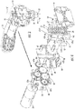
FIG. 4 is an exploded perspective view illustrating components of the hair band dispenser mechanism of the applicator apparatus; -
FIGS. 5A-5D are views illustrating a sequence of operation of the first and second band lifters of the hair band dispenser mechanism for dispensing a hair band; -
FIGS. 6A-6C are views illustrating use of the applicator apparatus in applying hair bands to strands of hair; -
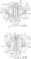
FIG. 7 is a view illustrating an alternate embodiment of the first and second band lifters incorporating a spring biased cam wall to permit use with different size band cartridges; -
FIG. 8 is a view similar to the view ofFIG. 7 illustrating a relative small diameter band cartridge positioned between the first and second band lifters ofFIG. 7 ; and -
FIG. 9 is a view similar to the view ofFIG. 7 illustrating a relative large diameter band cartridge positioned between the first and second band lifters ofFIG. 7 . - Particular embodiments of the present disclosure are described hereinbelow with reference to the accompanying drawings. However, it is to be understood that the disclosed embodiments are merely examples of the disclosure and may be embodied in various forms. Well-known functions or constructions are not described in detail to avoid obscuring the present disclosure in unnecessary detail. Therefore, specific structural and functional details disclosed herein are not to be interpreted as limiting, but merely as a basis for the claims and as a representative basis for teaching one skilled in the art to employ the present disclosure in virtually any appropriately detailed structure.
- The applicator apparatus of the present disclosure is adapted to individually and sequentially apply one or more hair bands to strands of hair. In general, the applicator apparatus incorporates first and second band lifters which undergo a sequence of movements to engage hair bands supported by a band cartridge and advance the hair bands along the band cartridge for release on strands of hair. The band cartridge supports the hair bands in spaced relation for sequential engagement of individual hair bands and maneuvering by the first and second hair band lifters.
- Referring now to
FIGS. 1-4 , theapplicator apparatus 10 for applying hair bands to strands of hair in accordance with the principles of the present disclosure is illustrated. Theapplicator apparatus 10 generally includes ahandle 12 and anapplicator head 14 extending from thehandle 12. Thehandle 12 is contoured for manual engagement by the user, and, in one embodiment, is elongated to enhance manipulation by the user. A switch button oractuator 16 is mounted to thehandle 12 to control operation of theapplicator apparatus 10. - The
applicator head 14 defines a longitudinal axis "k", and has alongitudinal opening 18 extending at least partially along the longitudinal axis "k". Theapplicator head 14 defines ahair entrance port 20 in communication with, or a component of, thelongitudinal opening 18, for reception of strands of hair. Aband cartridge 22 is mounted within thelongitudinal opening 18 in opposition to thehair entrance port 20. Theband cartridge 22 includes acartridge handle 24 and anelongated band support 26 depending from thecartridge handle 24. Theband cartridge 22 defines alongitudinal passage 28 therethrough which receives the strands of hair entering thelongitudinal opening 18 of theapplicator head 14 through thehair entrance port 20. Theelongated band support 26 supports a plurality ofhair bands 30 on its exterior. Thehair bands 30 are disposed in longitudinal spaced relation, and may be equidistantly spaced along the outer surface of theelongated band support 26. Thehair bands 30 may comprise an elastomeric material configured to expand and then return toward its original unexpanded state secured about strands of hair as is conventional in the art. Thehair bands 30 may be multi colored, possess ornamental features etc. - The
band cartridge 22 may be releasably mounted relative to theapplicator head 14. Any conventional methodologies for effecting releasable mounting of theband cartridge 22 to theapplicator head 14 are envisioned. In one embodiment, theapplicator head 14 includes acartridge lock button 32 which when in its normal inward position engages corresponding structure, e.g., a locking detent 34 (FIG. 2 ) of theband cartridge 22 to secure theband cartridge 22 relative to theapplicator head 14. Thecartridge lock button 32 may be pulled outwardly in the direction of directional arrow "m" (FIG. 3 ) to release thelocking detent 34 of theband cartridge 22 to permit removal of theband cartridge 22 subsequent to, e.g., depletion of thehair bands 30. In another embodiment, theband cartridge 22 may be releasably mounted to theapplicator head 14 through a friction or interference fit. Other methodologies are also envisioned. - Referring now to
FIG. 4 , the hair band dispenser mechanism of theapplicator apparatus 10 will be discussed. The hair dispenser mechanism includes amotor 36, aback plate 38 secured within theapplicator head 14 and a planetary gear set 40 coupled to thedrive shaft 36a of themotor 36 and supported by theback plate 38. Acam member 42 is operatively coupled to eachoutermost gear 40a of the planetary gear set 40 whereby rotation of the outermost 40a gears causes corresponding rotation of thecam members 42. Thecam members 42 are supported by a middle plate 44 disposed adjacent the planetary gear set 40. In one embodiment,cam shafts 42a of thecam members 42 extend throughcorresponding openings 46 of the middle plate 44 and couple with theoutermost gear 40a through, e.g., engagement with a corresponding dimensionedaperture 48 of eachoutermost gear 40a. Other arrangements are also envisioned. Thecam members 42 may define a reuleaux triangle whereby rotational movement of thecam member 42 may cause horizontal and vertical movement of a component thereby engaged. - The hair band dispenser mechanism further includes first and
second band lifters 50 which are disposed on opposed sides of the longitudinal axis "k", e.g., in diametrical opposed relation. The first andsecond band lifters 50 include cam mounts 52 which at least partially house thecam members 42, and respective first and secondband engaging elements 54 coupled to the cam mounts 52. The cam mounts 52 define internal first and second vertical surfaces 52v1, 52v2 and first and second horizontal surfaces 52h1, 52h2 which are engaged by thecam members 42 to effect the desired movement of the first andsecond band lifters 50. Theband engaging elements 54 include a plurality ofteeth 55. Longitudinallyadjacent teeth 55 defineband engaging grooves 56 therebetween spaced along the longitudinal axis "k". In one embodiment, the engaginggrooves 56 are equidistantly spaced along the longitudinal axis "k". Theband engaging grooves 56 are configured to receiverespective hair bands 30 on theband support 26 and move thehair bands 30 within theapplicator head 14 along theelongated band support 26 of the band cartridge 22 (e.g., through engagement with the teeth 55) and relative to the strands of hair. Afront plate 58 supports the first andsecond band lifters 50 and is secured to the middle plate 44 through conventional means. Amicroswitch 60 is positioned adjacent the cam mounts 52. - Referring now to
FIGS. 5A-5D , the operation of the hair band dispenser mechanism will be discussed.FIG. 5A illustrates the first andsecond band lifter 50 at a first longitudinal position and in a radial outward condition in position to engagehair bands 30. The user activates theactuator 16 to initiate activation of the hair band dispenser mechanism. Themotor 36 is activated to impart movement of theplanetary gear system 40 to rotate thecam member 42 from the first position depicted inFIG. 5A to the second position depicted inFIG. 5B . During this movement, thecam member 42 engages at least the second vertical surfaces 52v2 of the cam mounts 52 to move the first andsecond band lifters 50 radially inwardly to a radial inward condition whereby the receivinggrooves 56 of theband engaging elements 54 receive and engage thehair bands 30. Continued rotation of thecam members 42 causes the cam mounts 52 to move upwardly through, e.g., engagement with the second horizontal surface 52h2 to a second longitudinal position 52h2, releasing theuppermost hair band 30 onto hair as depicted inFIG. 5C . In one embodiment, theuppermost tooth 55u, or alternatively, an upper most surface of the first andsecond band lifters 50, drives theuppermost hair band 30 onto the strands of hair "h". Thecam members 42 continue to rotate and engage the first vertical surface 52v1 to drive the first andsecond band lifters 50 radially outwardly to a radial outward condition releasing thehair bands 30 as depicted inFIG. 5D . Continued rotation of thecam members 42 returns the cam mounts 52 to the first longitudinal position ofFIG. 5A . Upon return to the first longitudinal position, one of the cam mount 52 contacts themicroswitch 60 to deactivate themotor 36. The user may activate theactuator 16 to repeat the process and apply asecond hair band 30 onto the strands of hair. -
FIGS. 6A-6C illustrate application ofhair bands 30 onto strands of hair 'h". The strands of hair 'h" are introduced into thehair entrance port 20 of theapplicator head 14 and advanced through thelongitudinal passage 28 of theband cartridge 22 as depicted inFIG. 6A . Theactuator 16 is actuated to cause the hair band dispenser mechanism to proceed through the sequence of operations discussed inFIGS. 5A-5D to apply afirst hair band 30 to the strands of hair "h" as depicted inFIG. 6B . After application of the first band 30 (and all subsequent bands) themicroswitch 60 is contacted by thecam mount 52 to stop themotor 36. A nextsuccessive band 30 may be applied by activating theactuator 16 to place asecond band 30 onto the strands of hair "h". The process may be repeated to positionadditional bands 30 as depicted inFIG. 6C . Due to the longitudinal spacing of theband engaging grooves 56, thebands 30 are longitudinally spaced along the strands of hair "h" at substantially equal longitudinal increments. -
FIG. 7 illustrates an alternate embodiment which permits theapplicator apparatus 10 to accommodate differentdiameter band cartridges 22. In accordance with this embodiment, a spring biasedvertical cam wall 70 is disposed in eachcam mount 52. Specifically, acam wall 70 is disposed in eachcam mount 52 and adapted for reciprocal lateral movement within thecam mount 52 in the direction of directional arrows "b1, b2". Acoil spring 72 engages thecam wall 70 to normally bias thecam wall 70 radially outwardly. Upon insertion of a relatively smalldiameter band cartridge 22 as depicted inFIG. 8 , thecam wall 70 functions in a similar manner to the second vertical surface 52v2 discussed hereinabove to maneuver the cam mounts 52 and the first andsecond band lifters 50 through the sequence of movements discussed hereinabove in connection withFIGS. 5A-5D . It is noted that the spring constant of thecoil spring 72 may be selected to minimize or eliminate radial movement of thecam wall 70 such that thecam members 42 rotate to effect the desired movement of the cam mounts 52.FIG. 9 illustrates insertion of a largediameter band cartridge 22 within theapplicator head 14. Upon insertion of the largediameter band cartridge 22, the first andsecond band lifters 50 move radially outwardly with the radial displacing movement being accommodated by compression of thecoil spring 72 thereby maintaining thecam wall 70 in the desired position relative to thecam members 42. With either the smalldiameter band cartridge 22 or a largediameter band cartridge 22 positioned between the first andsecond band lifters 50, thecam members 42 rotate to engage the respective inner walls of the cam mounts 52 and thecam wall 70 to effect the desired sequence of movement disclosed in connection withFIGS. 5A-5D . - While several embodiments of the disclosure have been shown in the drawings and described herein, it is not intended that the disclosure be limited thereto, as it is intended that the disclosure be as broad in scope as the art will allow and that the specification be read likewise. Therefore, the above description should not be construed as limiting, but merely as examples of particular embodiments. Those skilled in the art will envision other modifications within the scope and spirit of the claims appended hereto.
Claims (15)
- An apparatus for applying hair bands to strands of hair, which comprises:a handle;an applicator head coupled to the handle, the applicator head defining a longitudinal axis and having a longitudinal opening for reception of strands of hair;a band cartridge mounted to the applicator head, the band cartridge supporting a plurality of hair bands;a hair band dispenser mechanism mounted at least partially in the applicator head, the hair band dispenser mechanism including first and second band lifters on opposed sides of the longitudinal axis, the first and second band lifters configured to move in radial inward directions to engage the hair bands of the band cartridge and translate in longitudinal directions to longitudinally displace the hair bands along the band cartridge for release on the strands of hair; anda motor operatively coupled to the first and second band lifters and configured to effect movement of the first and second band lifters.
- The apparatus according to claim 1 wherein the first and second band lifters each include a plurality of longitudinally spaced teeth, longitudinally adjacent teeth defining a groove therebetween configured to receive an individual hair band.
- The apparatus according to claim 2 wherein the band cartridge is configured for releasable mounting to the applicator head.
- The apparatus according to claim 3 wherein the band cartridge is in general alignment with the longitudinal axis and defines a longitudinal passage for reception of the strand of hairs.
- The apparatus according to claim 1 including a cam member operatively coupled to the motor, the cam member configured to rotate to move the first and second band lifters between first and second longitudinal positions and between radial inward and radial outward conditions.
- The apparatus according to claim 5 including a cam member associated with each of the first and second band lifters.
- The apparatus according to claim 6 including a manually engageable actuator configured to actuate the motor.
- The apparatus according to claim 7 including a switch in communication with the motor to deactivate the motor upon movement of the first and second band lifters to the first longitudinal position.
- The apparatus according to any of the previous claims, wherein the first and second band lifters each include a plurality of longitudinally spaced teeth with longitudinally adjacent teeth defining a groove therebetween, the first and second band lifters being configured to sequentially move in the following manner:1) from a radial outward condition to a radial inward condition at a first longitudinal position whereby grooves of the first and second band lifters receive respective hair bands supported by the band cartridge;2) from the first longitudinal position to a second longitudinal position to move the hair bands along the band cartridge and relative to the strands of hair;3) from the radial inward condition to the radial outward condition while in the second longitudinal position whereby the grooves of the first and second band lifters release the hair bands; and4) from the second longitudinal position to the first longitudinal position while in the radial outward condition; anda motor operatively coupled to the first and second band lifters and configured to effect movement of the first and second band lifters.
- The apparatus according to claim 9 wherein the band cartridge is releasably mounted to the applicator head, the band cartridge defining a longitudinal passage for reception of the strand of hairs.
- The apparatus according to claim 10 including a manually engageable actuator configured to actuate the motor.
- The apparatus according to claim 11 including a switch in communication with the motor to deactivate the motor upon movement of the first and second band lifters to the first longitudinal position.
- A method for applying hair bands to strands of hair, comprising:introducing strands of hair within a longitudinal opening of an applicator head of an applicator apparatus, the applicator head having a plurality of hair bands disposed in longitudinal spaced relation;passing the strands of hair through the longitudinal opening of the applicator head;moving first and second opposed band lifters of a hair band dispenser mechanism disposed at least partially in the head from a radial outward condition to a radial inward condition at a first longitudinal position to engage the hair bands;translating the first and second opposed band lifters along the longitudinal axis from the first longitudinal position to a second longitudinal position to move the hair bands within the longitudinal opening and relative to the strands of hair whereby an uppermost hair band is released onto the strands of hair;radially displacing the first and second opposed band lifters from the radial inward condition to the radial outward condition while in the second longitudinal position whereby the first and second band lifters release the hair bands; andreturning the first and second opposed band lifters to the first longitudinal position.
- The method according to claim 13 wherein the applicator apparatus includes a motor operatively coupled to the first and second opposed band lifters, and including activating the motor to effect movement of the first and second opposed band lifters.
- The method according to claim 14 including introducing a band cartridge within the longitudinal opening of the head, the band cartridge having the hair bands mounted in spaced relation.
Applications Claiming Priority (1)
| Application Number | Priority Date | Filing Date | Title |
|---|---|---|---|
| US15/463,684 US10631611B2 (en) | 2017-03-20 | 2017-03-20 | Apparatus for applying hair bands |
Publications (2)
| Publication Number | Publication Date |
|---|---|
| EP3378347A1 true EP3378347A1 (en) | 2018-09-26 |
| EP3378347B1 EP3378347B1 (en) | 2019-10-30 |
Family
ID=61655634
Family Applications (1)
| Application Number | Title | Priority Date | Filing Date |
|---|---|---|---|
| EP18161696.2A Active EP3378347B1 (en) | 2017-03-20 | 2018-03-14 | Apparatus for applying hair bands |
Country Status (6)
| Country | Link |
|---|---|
| US (1) | US10631611B2 (en) |
| EP (1) | EP3378347B1 (en) |
| JP (1) | JP3216458U (en) |
| CN (1) | CN208639767U (en) |
| CA (1) | CA2997983C (en) |
| MX (1) | MX384326B (en) |
Families Citing this family (2)
| Publication number | Priority date | Publication date | Assignee | Title |
|---|---|---|---|---|
| USD897598S1 (en) * | 2018-01-12 | 2020-09-29 | Shenzhen Yangwo Electronic Co., Ltd | Hair curler |
| US20240016119A1 (en) * | 2022-05-19 | 2024-01-18 | James Vernon Henrekin | Horse mane banding apparatus and method |
Citations (2)
| Publication number | Priority date | Publication date | Assignee | Title |
|---|---|---|---|---|
| US20140261525A1 (en) * | 2013-03-18 | 2014-09-18 | Tina Ward | Suction Powered Hair-Styling Device |
| WO2015193516A1 (en) * | 2014-12-22 | 2015-12-23 | Babyliss Faco Sprl | Hair-styling device |
Family Cites Families (8)
| Publication number | Priority date | Publication date | Assignee | Title |
|---|---|---|---|---|
| US6164291A (en) * | 2000-03-02 | 2000-12-26 | Filippone; Thomas C. | Retracting hairholder device |
| WO2004064568A1 (en) * | 2003-01-17 | 2004-08-05 | Elysee Beauty Products, Ltd. | Hair braider |
| US20090283108A1 (en) * | 2007-08-21 | 2009-11-19 | Patrick Brouillard | Hair braiding device |
| US7905237B2 (en) * | 2008-05-19 | 2011-03-15 | Jang Sik Noh | Hair braiding machine |
| KR101083972B1 (en) * | 2008-09-04 | 2011-11-21 | 주식회사 주산물산 | Wet Winding and Unwinding Device |
| US20160242521A1 (en) * | 2015-02-23 | 2016-08-25 | Luz C. Perez | Hair Retained Device Fastener |
| AU2015203226B8 (en) * | 2015-06-05 | 2021-04-15 | Ap Walker Design | Hair drying net and turban towel |
| GB201517902D0 (en) * | 2015-10-09 | 2015-11-25 | Fuse London Ltd | Apparatus and method for the weaving or interweaving of elongate members to form braids or plaits |
-
2017
- 2017-03-20 US US15/463,684 patent/US10631611B2/en active Active
-
2018
- 2018-03-12 CA CA2997983A patent/CA2997983C/en active Active
- 2018-03-14 EP EP18161696.2A patent/EP3378347B1/en active Active
- 2018-03-16 MX MX2018003338A patent/MX384326B/en unknown
- 2018-03-19 JP JP2018000993U patent/JP3216458U/en active Active
- 2018-03-20 CN CN201820379661.3U patent/CN208639767U/en active Active
Patent Citations (2)
| Publication number | Priority date | Publication date | Assignee | Title |
|---|---|---|---|---|
| US20140261525A1 (en) * | 2013-03-18 | 2014-09-18 | Tina Ward | Suction Powered Hair-Styling Device |
| WO2015193516A1 (en) * | 2014-12-22 | 2015-12-23 | Babyliss Faco Sprl | Hair-styling device |
Also Published As
| Publication number | Publication date |
|---|---|
| JP3216458U (en) | 2018-05-31 |
| EP3378347B1 (en) | 2019-10-30 |
| CN208639767U (en) | 2019-03-26 |
| US10631611B2 (en) | 2020-04-28 |
| MX2018003338A (en) | 2019-04-25 |
| MX384326B (en) | 2025-03-14 |
| CA2997983C (en) | 2019-07-02 |
| US20180263352A1 (en) | 2018-09-20 |
| CA2997983A1 (en) | 2018-05-21 |
Similar Documents
| Publication | Publication Date | Title |
|---|---|---|
| EP3378347B1 (en) | Apparatus for applying hair bands | |
| US20180214783A1 (en) | Spinning top launching device | |
| CN101374436A (en) | Hair braider | |
| US10869543B2 (en) | Pet grooming tool | |
| US20090255846A1 (en) | Case for consumer products | |
| WO1994022343A1 (en) | Hair treating and/or setting apparatus provided with a device for drawing out a curl | |
| CN106172293A (en) | Double-bearing reel | |
| KR101882811B1 (en) | Clutch assembly | |
| AU2014220395A1 (en) | Dispenser | |
| US9592938B2 (en) | Rotation mechanism and case assembly using the same | |
| CN107532699B (en) | Transmission delay unit and shutter lifting device | |
| JPH111816A (en) | Helmet having positioning knob freely adjustable according to wearer's head size | |
| JPH02274203A (en) | Hair-removing apparatus | |
| US20050076931A1 (en) | Hair accessory application device | |
| US20100198233A1 (en) | Epilator head for trapping hair and epilator with such head | |
| WO2012131416A1 (en) | Device and method for removing hair | |
| KR101609873B1 (en) | Handy cleaner | |
| GB2595755A (en) | Apparatus for forming braided elongate members | |
| CN110367676B (en) | Epilation head for an epilation device | |
| CN101491386B (en) | Curling comb with rotary drum | |
| JP7587527B2 (en) | Tool balancer | |
| JP2015231489A (en) | Coma toy launching device | |
| JP3873446B2 (en) | Hair removal equipment | |
| EP3846140A1 (en) | Dropping mechanism, storage apparatus, and self-service vending machine | |
| WO2016081735A1 (en) | Oil filter wrench |
Legal Events
| Date | Code | Title | Description |
|---|---|---|---|
| PUAI | Public reference made under article 153(3) epc to a published international application that has entered the european phase |
Free format text: ORIGINAL CODE: 0009012 |
|
| STAA | Information on the status of an ep patent application or granted ep patent |
Free format text: STATUS: THE APPLICATION HAS BEEN PUBLISHED |
|
| AK | Designated contracting states |
Kind code of ref document: A1 Designated state(s): AL AT BE BG CH CY CZ DE DK EE ES FI FR GB GR HR HU IE IS IT LI LT LU LV MC MK MT NL NO PL PT RO RS SE SI SK SM TR |
|
| AX | Request for extension of the european patent |
Extension state: BA ME |
|
| STAA | Information on the status of an ep patent application or granted ep patent |
Free format text: STATUS: REQUEST FOR EXAMINATION WAS MADE |
|
| 17P | Request for examination filed |
Effective date: 20190320 |
|
| RBV | Designated contracting states (corrected) |
Designated state(s): AL AT BE BG CH CY CZ DE DK EE ES FI FR GB GR HR HU IE IS IT LI LT LU LV MC MK MT NL NO PL PT RO RS SE SI SK SM TR |
|
| GRAP | Despatch of communication of intention to grant a patent |
Free format text: ORIGINAL CODE: EPIDOSNIGR1 |
|
| STAA | Information on the status of an ep patent application or granted ep patent |
Free format text: STATUS: GRANT OF PATENT IS INTENDED |
|
| INTG | Intention to grant announced |
Effective date: 20190522 |
|
| GRAS | Grant fee paid |
Free format text: ORIGINAL CODE: EPIDOSNIGR3 |
|
| GRAA | (expected) grant |
Free format text: ORIGINAL CODE: 0009210 |
|
| STAA | Information on the status of an ep patent application or granted ep patent |
Free format text: STATUS: THE PATENT HAS BEEN GRANTED |
|
| AK | Designated contracting states |
Kind code of ref document: B1 Designated state(s): AL AT BE BG CH CY CZ DE DK EE ES FI FR GB GR HR HU IE IS IT LI LT LU LV MC MK MT NL NO PL PT RO RS SE SI SK SM TR |
|
| REG | Reference to a national code |
Ref country code: GB Ref legal event code: FG4D |
|
| REG | Reference to a national code |
Ref country code: CH Ref legal event code: EP |
|
| REG | Reference to a national code |
Ref country code: AT Ref legal event code: REF Ref document number: 1195246 Country of ref document: AT Kind code of ref document: T Effective date: 20191115 |
|
| REG | Reference to a national code |
Ref country code: DE Ref legal event code: R096 Ref document number: 602018001004 Country of ref document: DE |
|
| REG | Reference to a national code |
Ref country code: IE Ref legal event code: FG4D |
|
| REG | Reference to a national code |
Ref country code: LT Ref legal event code: MG4D |
|
| PG25 | Lapsed in a contracting state [announced via postgrant information from national office to epo] |
Ref country code: PT Free format text: LAPSE BECAUSE OF FAILURE TO SUBMIT A TRANSLATION OF THE DESCRIPTION OR TO PAY THE FEE WITHIN THE PRESCRIBED TIME-LIMIT Effective date: 20200302 Ref country code: NL Free format text: LAPSE BECAUSE OF FAILURE TO SUBMIT A TRANSLATION OF THE DESCRIPTION OR TO PAY THE FEE WITHIN THE PRESCRIBED TIME-LIMIT Effective date: 20191030 Ref country code: BG Free format text: LAPSE BECAUSE OF FAILURE TO SUBMIT A TRANSLATION OF THE DESCRIPTION OR TO PAY THE FEE WITHIN THE PRESCRIBED TIME-LIMIT Effective date: 20200130 Ref country code: FI Free format text: LAPSE BECAUSE OF FAILURE TO SUBMIT A TRANSLATION OF THE DESCRIPTION OR TO PAY THE FEE WITHIN THE PRESCRIBED TIME-LIMIT Effective date: 20191030 Ref country code: NO Free format text: LAPSE BECAUSE OF FAILURE TO SUBMIT A TRANSLATION OF THE DESCRIPTION OR TO PAY THE FEE WITHIN THE PRESCRIBED TIME-LIMIT Effective date: 20200130 Ref country code: LT Free format text: LAPSE BECAUSE OF FAILURE TO SUBMIT A TRANSLATION OF THE DESCRIPTION OR TO PAY THE FEE WITHIN THE PRESCRIBED TIME-LIMIT Effective date: 20191030 Ref country code: PL Free format text: LAPSE BECAUSE OF FAILURE TO SUBMIT A TRANSLATION OF THE DESCRIPTION OR TO PAY THE FEE WITHIN THE PRESCRIBED TIME-LIMIT Effective date: 20191030 Ref country code: GR Free format text: LAPSE BECAUSE OF FAILURE TO SUBMIT A TRANSLATION OF THE DESCRIPTION OR TO PAY THE FEE WITHIN THE PRESCRIBED TIME-LIMIT Effective date: 20200131 Ref country code: SE Free format text: LAPSE BECAUSE OF FAILURE TO SUBMIT A TRANSLATION OF THE DESCRIPTION OR TO PAY THE FEE WITHIN THE PRESCRIBED TIME-LIMIT Effective date: 20191030 Ref country code: LV Free format text: LAPSE BECAUSE OF FAILURE TO SUBMIT A TRANSLATION OF THE DESCRIPTION OR TO PAY THE FEE WITHIN THE PRESCRIBED TIME-LIMIT Effective date: 20191030 |
|
| REG | Reference to a national code |
Ref country code: NL Ref legal event code: MP Effective date: 20191030 |
|
| PG25 | Lapsed in a contracting state [announced via postgrant information from national office to epo] |
Ref country code: HR Free format text: LAPSE BECAUSE OF FAILURE TO SUBMIT A TRANSLATION OF THE DESCRIPTION OR TO PAY THE FEE WITHIN THE PRESCRIBED TIME-LIMIT Effective date: 20191030 Ref country code: IS Free format text: LAPSE BECAUSE OF FAILURE TO SUBMIT A TRANSLATION OF THE DESCRIPTION OR TO PAY THE FEE WITHIN THE PRESCRIBED TIME-LIMIT Effective date: 20200229 Ref country code: RS Free format text: LAPSE BECAUSE OF FAILURE TO SUBMIT A TRANSLATION OF THE DESCRIPTION OR TO PAY THE FEE WITHIN THE PRESCRIBED TIME-LIMIT Effective date: 20191030 |
|
| PG25 | Lapsed in a contracting state [announced via postgrant information from national office to epo] |
Ref country code: AL Free format text: LAPSE BECAUSE OF FAILURE TO SUBMIT A TRANSLATION OF THE DESCRIPTION OR TO PAY THE FEE WITHIN THE PRESCRIBED TIME-LIMIT Effective date: 20191030 |
|
| PG25 | Lapsed in a contracting state [announced via postgrant information from national office to epo] |
Ref country code: RO Free format text: LAPSE BECAUSE OF FAILURE TO SUBMIT A TRANSLATION OF THE DESCRIPTION OR TO PAY THE FEE WITHIN THE PRESCRIBED TIME-LIMIT Effective date: 20191030 Ref country code: CZ Free format text: LAPSE BECAUSE OF FAILURE TO SUBMIT A TRANSLATION OF THE DESCRIPTION OR TO PAY THE FEE WITHIN THE PRESCRIBED TIME-LIMIT Effective date: 20191030 Ref country code: ES Free format text: LAPSE BECAUSE OF FAILURE TO SUBMIT A TRANSLATION OF THE DESCRIPTION OR TO PAY THE FEE WITHIN THE PRESCRIBED TIME-LIMIT Effective date: 20191030 Ref country code: DK Free format text: LAPSE BECAUSE OF FAILURE TO SUBMIT A TRANSLATION OF THE DESCRIPTION OR TO PAY THE FEE WITHIN THE PRESCRIBED TIME-LIMIT Effective date: 20191030 Ref country code: EE Free format text: LAPSE BECAUSE OF FAILURE TO SUBMIT A TRANSLATION OF THE DESCRIPTION OR TO PAY THE FEE WITHIN THE PRESCRIBED TIME-LIMIT Effective date: 20191030 |
|
| REG | Reference to a national code |
Ref country code: DE Ref legal event code: R097 Ref document number: 602018001004 Country of ref document: DE |
|
| REG | Reference to a national code |
Ref country code: AT Ref legal event code: MK05 Ref document number: 1195246 Country of ref document: AT Kind code of ref document: T Effective date: 20191030 |
|
| PG25 | Lapsed in a contracting state [announced via postgrant information from national office to epo] |
Ref country code: SM Free format text: LAPSE BECAUSE OF FAILURE TO SUBMIT A TRANSLATION OF THE DESCRIPTION OR TO PAY THE FEE WITHIN THE PRESCRIBED TIME-LIMIT Effective date: 20191030 Ref country code: SK Free format text: LAPSE BECAUSE OF FAILURE TO SUBMIT A TRANSLATION OF THE DESCRIPTION OR TO PAY THE FEE WITHIN THE PRESCRIBED TIME-LIMIT Effective date: 20191030 |
|
| PLBE | No opposition filed within time limit |
Free format text: ORIGINAL CODE: 0009261 |
|
| STAA | Information on the status of an ep patent application or granted ep patent |
Free format text: STATUS: NO OPPOSITION FILED WITHIN TIME LIMIT |
|
| 26N | No opposition filed |
Effective date: 20200731 |
|
| PG25 | Lapsed in a contracting state [announced via postgrant information from national office to epo] |
Ref country code: MC Free format text: LAPSE BECAUSE OF FAILURE TO SUBMIT A TRANSLATION OF THE DESCRIPTION OR TO PAY THE FEE WITHIN THE PRESCRIBED TIME-LIMIT Effective date: 20191030 |
|
| PG25 | Lapsed in a contracting state [announced via postgrant information from national office to epo] |
Ref country code: SI Free format text: LAPSE BECAUSE OF FAILURE TO SUBMIT A TRANSLATION OF THE DESCRIPTION OR TO PAY THE FEE WITHIN THE PRESCRIBED TIME-LIMIT Effective date: 20191030 Ref country code: AT Free format text: LAPSE BECAUSE OF FAILURE TO SUBMIT A TRANSLATION OF THE DESCRIPTION OR TO PAY THE FEE WITHIN THE PRESCRIBED TIME-LIMIT Effective date: 20191030 |
|
| PG25 | Lapsed in a contracting state [announced via postgrant information from national office to epo] |
Ref country code: LU Free format text: LAPSE BECAUSE OF NON-PAYMENT OF DUE FEES Effective date: 20200314 |
|
| PG25 | Lapsed in a contracting state [announced via postgrant information from national office to epo] |
Ref country code: IE Free format text: LAPSE BECAUSE OF NON-PAYMENT OF DUE FEES Effective date: 20200314 |
|
| REG | Reference to a national code |
Ref country code: DE Ref legal event code: R081 Ref document number: 602018001004 Country of ref document: DE Owner name: CONAIR LLC, STAMFORD, US Free format text: FORMER OWNER: CONAIR CORP., STAMFORD, CONN., US |
|
| REG | Reference to a national code |
Ref country code: CH Ref legal event code: PL |
|
| REG | Reference to a national code |
Ref country code: GB Ref legal event code: 732E Free format text: REGISTERED BETWEEN 20211014 AND 20211020 |
|
| PG25 | Lapsed in a contracting state [announced via postgrant information from national office to epo] |
Ref country code: CH Free format text: LAPSE BECAUSE OF NON-PAYMENT OF DUE FEES Effective date: 20210331 Ref country code: LI Free format text: LAPSE BECAUSE OF NON-PAYMENT OF DUE FEES Effective date: 20210331 |
|
| PG25 | Lapsed in a contracting state [announced via postgrant information from national office to epo] |
Ref country code: TR Free format text: LAPSE BECAUSE OF FAILURE TO SUBMIT A TRANSLATION OF THE DESCRIPTION OR TO PAY THE FEE WITHIN THE PRESCRIBED TIME-LIMIT Effective date: 20191030 Ref country code: MT Free format text: LAPSE BECAUSE OF FAILURE TO SUBMIT A TRANSLATION OF THE DESCRIPTION OR TO PAY THE FEE WITHIN THE PRESCRIBED TIME-LIMIT Effective date: 20191030 Ref country code: CY Free format text: LAPSE BECAUSE OF FAILURE TO SUBMIT A TRANSLATION OF THE DESCRIPTION OR TO PAY THE FEE WITHIN THE PRESCRIBED TIME-LIMIT Effective date: 20191030 |
|
| PG25 | Lapsed in a contracting state [announced via postgrant information from national office to epo] |
Ref country code: MK Free format text: LAPSE BECAUSE OF FAILURE TO SUBMIT A TRANSLATION OF THE DESCRIPTION OR TO PAY THE FEE WITHIN THE PRESCRIBED TIME-LIMIT Effective date: 20191030 |
|
| PGFP | Annual fee paid to national office [announced via postgrant information from national office to epo] |
Ref country code: GB Payment date: 20260219 Year of fee payment: 9 |
|
| PGFP | Annual fee paid to national office [announced via postgrant information from national office to epo] |
Ref country code: DE Payment date: 20260219 Year of fee payment: 9 |
|
| PGFP | Annual fee paid to national office [announced via postgrant information from national office to epo] |
Ref country code: BE Payment date: 20260219 Year of fee payment: 9 Ref country code: IT Payment date: 20260219 Year of fee payment: 9 |
|
| PGFP | Annual fee paid to national office [announced via postgrant information from national office to epo] |
Ref country code: FR Payment date: 20260219 Year of fee payment: 9 |