EP3377452B1 - Method and apparatuses for forming glass ribbons - Google Patents
Method and apparatuses for forming glass ribbons Download PDFInfo
- Publication number
- EP3377452B1 EP3377452B1 EP16806320.4A EP16806320A EP3377452B1 EP 3377452 B1 EP3377452 B1 EP 3377452B1 EP 16806320 A EP16806320 A EP 16806320A EP 3377452 B1 EP3377452 B1 EP 3377452B1
- Authority
- EP
- European Patent Office
- Prior art keywords
- heating
- forming
- heating cartridge
- root
- heat directing
- Prior art date
- Legal status (The legal status is an assumption and is not a legal conclusion. Google has not performed a legal analysis and makes no representation as to the accuracy of the status listed.)
- Active
Links
Images





Classifications
-
- C—CHEMISTRY; METALLURGY
- C03—GLASS; MINERAL OR SLAG WOOL
- C03B—MANUFACTURE, SHAPING, OR SUPPLEMENTARY PROCESSES
- C03B17/00—Forming molten glass by flowing-out, pushing-out, extruding or drawing downwardly or laterally from forming slits or by overflowing over lips
- C03B17/06—Forming glass sheets
- C03B17/067—Forming glass sheets combined with thermal conditioning of the sheets
-
- C—CHEMISTRY; METALLURGY
- C03—GLASS; MINERAL OR SLAG WOOL
- C03B—MANUFACTURE, SHAPING, OR SUPPLEMENTARY PROCESSES
- C03B17/00—Forming molten glass by flowing-out, pushing-out, extruding or drawing downwardly or laterally from forming slits or by overflowing over lips
- C03B17/06—Forming glass sheets
- C03B17/064—Forming glass sheets by the overflow downdraw fusion process; Isopipes therefor
-
- Y—GENERAL TAGGING OF NEW TECHNOLOGICAL DEVELOPMENTS; GENERAL TAGGING OF CROSS-SECTIONAL TECHNOLOGIES SPANNING OVER SEVERAL SECTIONS OF THE IPC; TECHNICAL SUBJECTS COVERED BY FORMER USPC CROSS-REFERENCE ART COLLECTIONS [XRACs] AND DIGESTS
- Y02—TECHNOLOGIES OR APPLICATIONS FOR MITIGATION OR ADAPTATION AGAINST CLIMATE CHANGE
- Y02P—CLIMATE CHANGE MITIGATION TECHNOLOGIES IN THE PRODUCTION OR PROCESSING OF GOODS
- Y02P40/00—Technologies relating to the processing of minerals
- Y02P40/50—Glass production, e.g. reusing waste heat during processing or shaping
-
- Y—GENERAL TAGGING OF NEW TECHNOLOGICAL DEVELOPMENTS; GENERAL TAGGING OF CROSS-SECTIONAL TECHNOLOGIES SPANNING OVER SEVERAL SECTIONS OF THE IPC; TECHNICAL SUBJECTS COVERED BY FORMER USPC CROSS-REFERENCE ART COLLECTIONS [XRACs] AND DIGESTS
- Y02—TECHNOLOGIES OR APPLICATIONS FOR MITIGATION OR ADAPTATION AGAINST CLIMATE CHANGE
- Y02P—CLIMATE CHANGE MITIGATION TECHNOLOGIES IN THE PRODUCTION OR PROCESSING OF GOODS
- Y02P40/00—Technologies relating to the processing of minerals
- Y02P40/50—Glass production, e.g. reusing waste heat during processing or shaping
- Y02P40/57—Improving the yield, e-g- reduction of reject rates
Definitions
- the present specification generally relates to methods and apparatuses for making glass ribbons.
- Glass forming apparatuses are commonly used to form various glass products such as glass sheets used for LCD displays and the like. These glass sheets may be manufactured by downwardly flowing molten glass over a forming wedge to form a continuous glass ribbon. Developing technologies are using glass compositions with increasingly lower liquidus viscosities. As such, higher forming temperatures are used to prevent devitrification of molten glass as it traverses the forming wedge.
- an apparatus for forming a glass ribbon includes a forming wedge disposed in a housing and including a pair of downwardly inclined forming surface portions converging at a root.
- a plurality of heating cartridges may be positioned in ports of the housing.
- Each heating cartridge includes a heat directing surface that is oriented at an angle of greater than about 90° with respect to a bottom surface of the heating cartridge, such that the heat directing surface is downward-facing .
- the heat directing surface includes at least one heating element positioned adjacent to the heat directing surface.
- the heating cartridge is positioned such that the heat directing surface faces the forming wedge and an upper edge of the heat directing surface is positioned above the root to direct heat from the heat directing surface towards the root of the forming wedge.
- a view factor from the heat directing surface may be greater below a top surface of the heating cartridge than above the top surface of the heating cartridge.
- An upper edge of the heat directing surface and the top surface of the heating cartridge may thermally shield an area above the heat directing surface from an area below the heat directing surface.
- an apparatus for making glass ribbons includes a forming wedge disposed in a housing and comprising a pair of downwardly inclined forming surface portions converging at a root.
- a plurality of heating cartridges may be positioned in ports of the housing.
- Each heating cartridge includes a heat directing surface that is oriented at an angle of greater than about 90° with respect to a bottom surface of the heating cartridge.
- the heat directing surface includes a heating element positioned adjacent to the heat directing surface.
- the heating cartridge is positioned such that the heat directing surface faces the forming wedge and an upper edge of the heat directing surface and a top surface of the heating cartridge are positioned above at least one of the root of the forming wedge.
- Ranges can be expressed herein as from “about” one particular value, and/or to "about” another particular value. When such a range is expressed, another embodiment includes from the one particular value and/or to the other particular value. Similarly, when values are expressed as approximations, by use of the antecedent "about,” it will be understood that the particular value forms another embodiment. It will be further understood that the endpoints of each of the ranges are significant both in relation to the other endpoint, and independently of the other endpoint.
- the glass forming apparatus 10 generally includes a melting vessel 15 configured to receive glass batch material 16 from a storage bin 18.
- the glass batch material 16 can be introduced to the melting vessel 15 by a batch delivery device 20 powered by a motor 22.
- An optional controller 24 may be provided to activate the motor 22 and a molten glass level probe 28 can be used to measure the glass melt level within a standpipe 30 and communicate the measured information to the controller 24.
- the glass forming apparatus 10 includes a fining vessel 38, such as a fining tube, located downstream from the melting vessel 15 and coupled to the melting vessel 15 by way of a first connecting tube 36.
- a mixing vessel 42 such as a stir chamber, is located downstream from the fining vessel 38.
- a delivery vessel 46 such as a bowl, may be located downstream from the mixing vessel 42.
- a second connecting tube 40 couples the fining vessel 38 to the mixing vessel 42 and a third connecting tube 44 couples the mixing vessel 42 to the delivery vessel 46.
- a downcomer 48 is positioned to deliver glass melt from the delivery vessel 46 to an inlet 50 of a forming vessel 60.
- the melting vessel 15 is typically made from a refractory material, such as refractory (e.g., ceramic) brick.
- the glass forming apparatus 10 may further include components that are typically made from platinum or platinum-containing metals such as platinum-rhodium, platinum-iridium and combinations thereof, but which may also comprise such refractory metals such as molybdenum, palladium, rhenium, tantalum, titanium, tungsten, ruthenium, osmium, zirconium, and alloys thereof and/or zirconium dioxide.
- the platinum-containing components can include one or more of the first connecting tube 36, the fining vessel 38, the second connecting tube 40, the standpipe 30, the mixing vessel 42, the third connecting tube 44, the delivery vessel 46, the downcomer 48 and the inlet 50.
- the forming vessel 60 can also be made from a refractory material (for example, refractory brick and/or refractory metal) and is designed to form the glass melt into a glass ribbon 12.
- FIG. 2 is a cross sectional perspective view of the glass forming apparatus 10 along line 2-2 of FIG. 1 .
- the forming vessel 60 includes a forming wedge 62 comprising an upwardly (i.e in the +x direction of the coordinate axes depicted in FIG. 2 ) open trough 61, a pair of downwardly (i.e., in the -x direction of the coordinate axes depicted in FIG. 2 ) inclined forming surface portions 66a, 66b that extend between opposed ends 64a, 64b of the forming wedge 62.
- the downwardly inclined forming surface portions 66a, 66b that converge along a downstream direction 68 to form a root 70.
- a draw plane 72 extends through the root 70.
- the glass ribbon 12 may be drawn from the forming wedge 62 in the downstream direction 68 along the draw plane 72, as will be described further herein.
- the draw plane 72 bisects the root 70 in a generally horizontal, lengthwise direction (the +/-y direction of the coordinate axes depicted in FIG. 2 ) of the forming vessel 60 through the root 70.
- the draw plane 72 may extend at other various orientations with respect to the root 70 other than bisecting the forming vessel 60 through the root.
- FIGS. 1 and 2 generally depict one embodiment of a glass forming apparatus and a forming vessel, it should also be understood that aspects of the present disclosure may be used with various other forming vessel configurations.
- the forming vessel 60 may comprise an edge director 80a, 80b intersecting with the pair of downwardly inclined forming surface portions 66a, 66b.
- the edge directors help achieve a desired glass ribbon width and edge characteristics by directing the molten glass proximate to the root 70 of the forming vessel 60.
- the edge director can intersect with both downwardly inclined forming surface portions 66a, 66b.
- an edge director can be positioned at each of the opposed ends 64a, 64b of the forming wedge 62. For instance, as shown in FIG.
- an edge director 80a, 80b can be positioned at each of the opposed ends 64a, 64b of the forming wedge 62 with each edge director 80a, 80b configured to intersect with both of the downwardly inclined forming surface portions 66a, 66b.
- each edge director 80a, 80b is substantially identical to one another.
- the edge directors may have different configurations and/or geometries depending on the specific characteristics of the glass forming apparatus.
- various forming wedge and edge director configurations may be used in accordance with aspects of the present disclosure. For example, aspects of the present disclosure may be used with forming wedges and edge director configurations as disclosed in U.S. Pat. Nos.
- the glass forming apparatus 10 can optionally include at least one edge roller assembly (not shown) for drawing glass ribbon from the root 70 of the forming vessel 60.
- edge roller assembly (not shown) for drawing glass ribbon from the root 70 of the forming vessel 60.
- edge roller assembly configurations may be used in accordance with aspects of the present disclosure.
- aspects of the present disclosure may be used with edge roller assembly configurations as disclosed in U.S. Pat. Application No. 14/278582, filed May 15, 2014 .
- a housing 14 encloses the forming vessel 60.
- the housing 14 may be formed from steel and contain refractory material and/or insulation to thermally insulate the forming vessel 60, and the molten glass flowing in and around the forming vessel 60, from the surrounding environment.
- batch material 16 specifically batch material for forming glass
- the batch material 16 is fed from the storage bin 18 into the melting vessel 15 with the batch delivery device 20.
- the batch material 16 is melted into molten glass in the melting vessel 15.
- the molten glass passes from the melting vessel 15 into the fining vessel 38 through the first connecting tube 36.
- Dissolved gasses which may result in glass defects, are removed from the molten glass in the fining vessel 38.
- the molten glass then passes from the fining vessel 38 into the mixing vessel 42 through the second connecting tube 40.
- the mixing vessel 42 homogenizes the molten glass, such as by stirring, and the homogenized molten glass passes through the third connecting tube 44 to the delivery vessel 46.
- the delivery vessel 46 discharges the homogenized molten glass through downcomer 48 and into the inlet 50 which, in turn, passes the homogenized molten glass into the trough 61 of the forming vessel 60.
- the glass ribbon 12 may be drawn in the downstream direction 68 along the draw plane 72 that extends through the root 70.
- glass forming apparatuses As depicted in FIGS. 1-2 , it has been found that developing technologies such as high performance displays (HPD) utilizing organic light emitting diode (OLED) technology benefit from glass compositions that are difficult to form, such as glass compositions with lower liquidus viscosities. Such glass compositions typically are made with higher forming temperatures to prevent the formation of defects, such as devitrification, in the glass ribbon drawn from the forming vessel 60.
- the glass forming apparatuses described herein utilize heating cartridges positioned proximate the root of the forming vessel 60 to maintain the molten glass at relatively high forming temperatures thereby aiding the sheet-forming process and preventing the formation of defects in the glass ribbon.
- the glass forming apparatus 10 further includes a plurality of heating cartridges 110, 111 positioned in a series of ports 112 formed in the housing 14 and/or housing seal plate 136 ( FIG. 3 ).
- the housing seal plate 136 forms part of housing 14 ( FIGS. 1-2 ). As shown in FIG.
- a first series of ports 112 and a second series of ports are arranged so that a first plurality of heating cartridges 110 and a second plurality of heating cartridges 111 are located on opposite sides of the root 70 such that the draw plane 72 extends between the first plurality of heating cartridges 110 and the second plurality of heating cartridges 111.
- the first plurality of heating cartridges 110 and the first series of ports 112 will be described in more detail. However, it should be understood that the first plurality of heating cartridges 110 and the second plurality of heating cartridges 111 are substantially identical or of a similar construct to the other. Similarly, it should be understood that each series of ports 112 are substantially identical or of a similar construct to the other.
- the first series of ports 112 are arrayed across the width (the +/-y direction of the coordinate axes depicted in FIGS. 1 and 2 ) of the forming vessel 60 so that the first series of ports 112 spans the width (the +/-y direction of the coordinate axes depicted in FIGS. 1 and 2 ) of the draw plane 72 on which the glass ribbon 12 is drawn. Accordingly, it should be understood that the first plurality of heating cartridges 110, when inserted in the corresponding ports, are also arrayed across the width of the forming vessel 60 and extend across the width of the draw plane 72 of the glass ribbon 12.
- each port of the first series of ports 112 are spaced laterally (i.e., in the +/-y direction of the coordinate axes depicted in FIGS. 1 and 2 ) apart from one another across the width of the forming vessel. In certain embodiments, each port of the first series of ports 112 can be spaced laterally apart from one another by an equal distance.
- the first plurality of heating cartridges 110 may be configured to direct heat onto the root 70, thereby maintaining the root 70 at a desired temperature, such as above the divitrification temperature of the molten glass and, in turn, mitigating the formation of defects in the glass.
- the first series of ports 112 can be located in the housing 14 such that the first plurality of heating cartridges 110 are positioned adjacent to and spaced from the root 70 of the forming vessel 60 in the -z direction. In the embodiment depicted in FIG.
- the first plurality of heating cartridges 110 are spaced from the root 70 in the -z direction, and further positioned such that a portion of each heating cartridge 110 is located above (the +x direction of the coordinate axes) the root 70 and a portion is located below (in the -x direction of the coordinate axes) the root 70.
- the first series of ports 112 can be located in the housing 14 such that the first plurality heating cartridges 110 are positioned entirely above the root 70.
- the first series of ports 112 can be located in the housing 14 such that the first plurality heating cartridges 110 are positioned below the root 70.
- FIGS. 1-3 depict a first plurality of heating cartridges 110 that includes five heating cartridges 110a, 110b, 110c, 110d, 110e.
- FIGS. 1-3 depict that these five heating cartridges are positioned in a first series of ports 112 that includes five ports 112a, 112b, 112c, 112d, 112e formed in the housing 14.
- this is an exemplary number and that the number of heating cartridges in the first plurality of heating cartridges 110 and the number of corresponding ports in the first series of ports 112 may be more than five or less than five.
- the width of the heating cartridges depends on the number of heating cartridges utilized as well as the width of the forming vessel. For example, FIG.
- FIGS. 23 illustrate five heating cartridges across less than the full width of the forming vessel.
- One of the first plurality of heating cartridges 110 will be described in more detail herein. However, it should be understood that each heating cartridge 110a, 110b, 110c, 110d, 110e of the first plurality of heating cartridges 110, as well as each heating cartridge of the second plurality of heating cartridges 111, is substantially identical or of a similar construct..
- each of the first plurality of heating cartridges 110 includes an enclosure 120 having a heat directing surface 122 with at least one heating element 124 positioned on or adjacent to the face thereof.
- the enclosure 120 may be fabricated from a variety of materials suitable for use at the elevated temperature conditions associated with the glass forming apparatus 10.
- the enclosure 120, and other portions of the heating cartridge 110a can be formed from a refractory material such as high temperature nickel-based alloys, steel (e.g., stainless steel), or other alloys or materials (or combinations of materials), to meet the structural and/or thermal parameters associated with the glass forming apparatus 10.
- the enclosure 120 may be made of nickel-based alloys, such as Haynes ® 214 ® nickel-based alloy produced by Haynes International, Inc.
- FIGS. 3-5 depict the heating cartridge 110a as comprising an enclosure, it should be understood that other embodiments are contemplated and possible.
- the heat directing surface 122 may be affixed to a block (or blocks) of refractory materials instead of having a separate enclosure formed from metals/alloys.
- the heat directing surface is affixed to a body formed from NA-33 refractory blocks produced by ANH refractories.
- the heat directing surface 122 of the heating cartridge 110a is formed from a ceramic refractory backer material with low emissivity.
- Suitable ceramic refractory materials include, without limitation, SALI board available from Zircar ceramics.
- Portions of the heating cartridge 110a which are not directly exposed to the high temperatures of the glass forming apparatus 10 may be made from materials suitable for lower temperature applications.
- the heating cartridge 110a comprises an enclosure
- the back face 125 of the enclosure 120 may be made from stainless steel selected to meet the structural and/or thermal parameters associated with the glass forming apparatus 10, such as, for example, 420 stainless steel.
- the heat directing surface 122 of the heating cartridge 110a is oriented at an angle ⁇ with respect to a bottom surface 126 of the heating cartridge 110a
- the angle ⁇ is greater than 90°.
- the angle ⁇ of the heat directing surface 122 may be from about 120° to about 150° relative to the bottom surface 126 of the heating cartridge 110a.
- the angle ⁇ of the heat directing surface 122 may be from about 130° to about 140° relative to the bottom surface 126 of the heating cartridge 110a.
- the angle ⁇ of the heat directing surface 122 is about 135° relative to the bottom surface 126 of the heating cartridge 110a.
- the downward-facing orientation of the heat directing surface 122 facilitates positioning the heating cartridge 110a in the housing 14 of the glass forming apparatus 10 such that the heat directing surface 122 of each replaceable heating cartridge faces the root 70 of the forming vessel 60.
- the downward facing orientation of the heat directing surface 122 enables the heat directing surface 122 to radiate and direct heat toward and onto the root 70 of the forming vessel 60 with only minimal loss of heat to the surrounding environment, particularly to areas above the root 70, such as areas above the heating cartridge.
- the heating cartridge 110a is positioned in the housing 14 of the glass forming apparatus 10 such that the upper edge 123 of the heat directing surface 122 and the top surface 127 of each heating cartridge 110a are positioned above the root 70.
- This positioning enables the heat directing surface 122 of the heating cartridge 110a to direct heat towards and onto the root 70 of the forming vessel 60, thereby increasing the temperature of the root 70 as well as the temperature of the molten glass flowing over the forming vessel 60 in the area of the root 70.
- the heating cartridge 110a can be positioned entirely upstream from the root 70.
- FIG. 1 the heating cartridge 110a can be positioned entirely upstream from the root 70.
- the heating cartridge 110a can be positioned partially upstream from the root 70.
- the top surface 127 of the heating cartridge 110a can be positioned upstream from the root 70 while the bottom surface 126 of the heating cartridge 110a is positioned downstream from the root 70.
- Positioning the heating cartridge 110a partially upstream from the root 70 may provide adequate heating to the root 70 to prevent devitrification of the molten glass while reducing heat loss to non-target areas above the root 70 due to the angled heat directing face of the heating cartridge.
- positioning the heating cartridge 110a partially upstream from the root 70 may allow the heating cartridge, specifically the heat directing surface 122, to be positioned closer to the root 70 such that a greater amount of heat is incident on the root 70 and the molten glass flowing over the root 70.
- the angle of the heat directing surface 122 and the position of the heating cartridge 110a within the housing 14 is such that the view factor from the heat directing surface is greater for objects (such as the root 70 of the forming vessel 60) located below the top surface 127 of the heating cartridge 110a than objects located above the top surface 127 of the heating cartridge 110a.
- view factor refers to the relative proportion of thermal radiation from the heat directing surface 122 which is incident on the specified surface.
- the view factor from the heat directing surface 122 is greater for objects (such as the root 70 of the forming vessel 60) located below the top surface 127 of the heating cartridge 110a than objects located above the top surface 127 of the heating cartridge 110a, objects located below the top surface 127 of the heating cartridge 110a will receive a greater amount of heat flux from the heat directing surface 122 of the heating cartridge 110a than objects located above the top surface 127 of the heating cartridge 110a.
- the heating cartridge 110 may be positioned downstream of the root 70 (i.e., in the -x direction). In these embodiments, the heat directing face of the heating cartridge may be angled to direct heat towards the root 70 as the heat rises along the angled heat directing face.
- the heating cartridge 110a can function as both a heater for heating the root 70 as well as a thermal shield to thermally isolate and shield the area above the heating cartridge 110a from an area below the heating cartridge 110a, thereby preventing the loss of heat from the root 70 and molten glass flowing over the root 70 to non-target areas located above of the root 70 of the forming vessel 60.
- the heat directing surface 122 of the heating cartridge 110a is oriented at an angle ⁇ that is greater than 90° with respect to the bottom surface 126 of the heating cartridge 110a.
- the top surface 127 of the heating cartridge 110a and the upper edge 123 of the heat directing surface 122 are cantilevered over the lower edge 129 and bottom surface 126 of the heating cartridge 110a.
- This arrangement of the heat directing surface 122 creates the view factor of the heating cartridge as described herein.
- the cantilevered arrangement of the heat directing surface 122 extends the heat directing surface 122 across a gap 170 between the heat directing surface 122 and the forming vessel 60, decreasing the spacing between the forming vessel 60 and the heating cartridges and slowing the loss of heat from areas downstream of the root to areas of the glass forming apparatus 10 located upstream of the root 70 of the forming vessel 60.
- the heating cartridge 110a also thermally shields areas above the heat directing surface 122 from areas below the heat directing surface 122.
- the heating element 124 positioned on or adjacent to the heat directing surface 122 is a resistance heating element.
- the material of the resistance heating element can be molybdenum disilicide.
- the heating element 124 may be constructed from wire formed from molybdenum disilicide.
- the heating element 124 may be constructed from a molybdenum disilicide wire that is positioned on the heat directing surface 122 in a serpentine shape.
- a heating element 124 formed from molybdenum disilicide can include a winding element positioned on the heat directing surface 122. The ends of the heating element 124 extending through the heating cartridge 110a may have a diameter selected to minimize power losses away from the heat directing surface 122.
- forming heating cartridge as described herein can greatly improve the heating efficiency of the heating cartridge. This may be attributable to the increased power-carrying capacity of the molybdenum disilicide heating element compared to other materials as well as the additional refractory material insulation and the angled heat directing surface. Further, it has also been found that the combination of segmented heating cartridges, such as the heating cartridges described herein, and molybdenum disilicide heating elements allows for higher forming temperatures at the root 70 than other conventional heating element materials. This enables, for example, the use of higher forming temperatures which, in turn, prevents devitrification of molten glass and mitigates defects in the glass ribbon drawn from the root 70 of the forming vessel 60. Additionally, with forming temperatures at the root 70 being equal, molybdenum disilicide heating elements advantageously achieve such forming temperatures with lower power input than used with conventional heating element materials.
- FIG. 4A depicts a single heating element 124 positioned on the heat directing surface 122 of the heating cartridge 110a
- the heating element 124 may be a segmented heating element which includes two or more separate heating elements, each of which may be separately powered and controlled. This allows the heat directing surface 122 of the heating cartridge 110a to be formed with individual heating zones which may be independently controlled, thereby providing more refined control of the temperature profile of the heat directing surface 122.
- refractory material 128 located behind the face of the heat directing surface 122 are one or more blocks of refractory material 128 which insulate the heat directing surface 122 from the balance of the heating cartridge 110a. These blocks of refractory material 128 may be located within an enclosure 120 as depicted in FIGS. 4 and 5 or, alternatively, attached directly to the heat directing surface 122 without an enclosure. In certain embodiments the refractory materials 128 are oriented to minimize heat transfer from the heat directing surface 122.
- the refractory materials 128 are oriented in alternating vertical stacks and horizontal stacks, as it is believed that alternating vertical stacks and horizontal stacks of refractory material 128 may assist in reducing heat at seams between the blocks.
- the refractory material 128 can be oriented at an angle approximately equal to the angle of the heat directing surface 122.
- the heat directing surface 122 is formed from a refractory material such as SALI board or the like, the refractory material of the heat directing surface 122 may extend into the enclosure.
- the refractory material 128 may be commercially available refractory materials including, without limitation, SALI board, Insulating Fire Brick (IFB), DuraBoard ® 3000 and/or DuraBoard ® 2600.
- the refractory blocks may have a first layer closest to the heat directing surface 122 formed from SALI board and a second layer located behind the first layer formed from IFB.
- a variety of attachment structures may be used to mount the heating cartridge 110a with respect to the root 70.
- the heating cartridge 110a may be mounted on a bracket 114 engaged with the housing 14 and/or the housing seal plate 136, as depicted in FIG 3 . Additionally or alternatively, the heating cartridge 110a can rest on T-wall support brackets 116 that are attached to housing 14 and/or the housing seal plate 136, as depicted in FIG 2 .
- each of the heating cartridges is removably mounted in the ports of the housing 14 of the glass forming apparatus 10. Each individual heating cartridge can be independently controlled so that using the plurality of heating cartridges one can reach a desired temperature distribution across the root of the forming wedge.
- each heating cartridge minimizes the impact of a failed heating element and/or the replacement of a heating cartridge. That is, in the event that a single heating element fails during operation, the failure of that heating element results in the loss of only a fraction of the total heating. Moreover, because the heating cartridges are separately controlled, the adjacent heating cartridges may be individually adjusted to offset the loss of heating from a failed heating element. Further, the modular nature of the heating cartridges means that replacement of an individual cartridge impacts only a fraction of the total heating provided, thereby reducing production losses.
- the apparatus may further include a controller 180 configured to control heating associated with the plurality of heating cartridges 110,111.
- the controller 180 may be operably connected to each heating cartridge of the plurality of heating cartridges 110,111, as depicted in FIG 1 .
- control of individual ones of the plurality of heating cartridges 110,111 can be segmented.
- the term "segmented,” as used herein, refers to the ability to independently control and adjust the temperature of each individual heating cartridge in order to provide managed control of the temperature of the glass ribbon during manufacture.
- the controller may include a processor and memory storing computer readable and executable instructions which, when executed by the processor, individually regulates the power to each heating cartridge, thereby individually increasing or decreasing the heat provided by each heating cartridge based on temperature feedback or other process parameters.
- the controller 180 may be used to differentially regulate the power that is provided to each heating cartridge of the plurality of heating cartridges 110,111 that span the width of the root 70 and the width of the draw plane 72 of the glass ribbon 12.
- the controller 180 can be configured to individually operate each heating cartridge of the plurality of heating cartridges 110,111 based on thermal feedback from the glass forming apparatus.
- the controller 180 is configured to obtain thermal feedback from a thermal sensor 182, as depicted in FIG. 1 .
- the feedback obtained by the thermal sensor can be used by the controller 180 to individually adjust each heating cartridge of the plurality of heating cartridges 110,111 in order to provide managed control of a thermal characteristic of the apparatus as the manufacture of glass ribbon proceeds.
- the thermal characteristic can include, for example, the temperature and/or heat loss associated with: a portion of the glass forming apparatus, such as the heat directing surface 122 of each heating cartridge of the plurality of heating cartridges 110,111; a portion of the edge directors 80a, 80b; a portion of the end of the forming vessel 60; portions of the molten glass; and/or other features of the glass forming apparatus 10.
- the thermal sensor 182 may detect a temperature above a target level and the controller 180 may reduce power to at least one heating cartridge of the plurality of heating cartridges 110,111 such that less heat is transferred to the target area, thereby reducing the temperature until the target level temperature is obtained.
- the thermal sensor 182 may detect a temperature below a target level, wherein the controller 180 may increase power to at least one heating cartridge of the plurality of heating cartridges 110,111, such that more heat is transferred to the target area, thereby increasing the temperature until the target level temperature is obtained.
- the controller 180 may provide more power and heat to the heating cartridges of the plurality of heating cartridges 110, 111 that are located proximate the edges (the +/-y direction of the coordinate axes depicted in FIG. 2 ) of the draw plane 72 of the glass ribbon 12 than to the heating cartridges located in the middle of the draw plane 72 to compensate for both the heat lost in these areas as well as to account for the greater thickness of glass proximate the edges of the draw plane 72.
- the controller can be configured to individually operate each heating cartridge of the plurality of heating cartridges 110, 111 based on thermal feedback from the glass forming apparatus 10.
- the controller is configured to obtain thermal feedback from at least one thermal sensor (not shown) positioned proximate to the root 70 of the forming vessel 60.
- the feedback obtained by the at least one thermal sensor can be used by the controller to individually adjust each heating cartridge of the plurality of heating cartridges 110, 111 in order to provide managed control of a thermal characteristic of the apparatus as the manufacture of glass ribbon proceeds.
- the thermal characteristic can include, for example, the temperature and/or heat loss associated with: a portion of the glass forming apparatus 10, such as the heat directing surface 122 of a heating cartridge 1 10a; the root 70; a portion of the end of the forming vessel 60; portions of the molten glass; and/or other features of the glass forming apparatus 10.
- the at least one thermal sensor may detect a temperature above a target level and the controller may individually reduce power to at least one of heating cartridges of the plurality of heating cartridges 110, 111 such that less heat is transferred to the target area, thereby reducing the temperature until the target level temperature is obtained.
- the at least one thermal sensor may detect a temperature below a target level, wherein the controller may individually increase power to at least one of the heating cartridges of the plurality of heating cartridges 110, 111, such that more heat is transferred to the target area, thereby increasing the temperature until the target level temperature is obtained.
- FIGS. 1-3 schematically depict one embodiment of a glass forming apparatus 10 in which heating cartridges 110a-110e are positioned proximate a root 70 of the forming wedge 62
- the plurality of heating cartridges may be positioned proximate the trough 61 of the forming vessel 60.
- the forming vessel 60 is positioned in a housing (not shown) and may include a trough 61 for receiving molten glass and a pair of downwardly inclined forming surface portions 66a, 66b converging at a root 70, as described hereinabove.
- a plurality of heating cartridges 110a-110e may be removably positioned in ports formed in the housing, as described hereinabove, such that a heat directing surface 122 of each of the heating cartridges faces the forming vessel 60 and an upper edge 123 of the heat directing surface 122 and a top surface 127 of the heating cartridge are positioned above the trough 61 of the forming vessel 60 to direct heat from the heat directing surface 122 of the heating cartridge towards the trough 61 of the forming vessel 60, thereby heating the glass at the top of the weirs 63 of the trough 61 of the forming vessel 60 and preventing devitrification.
- each heating cartridge may have substantially the same structure as shown and described herein with respect to FIGS. 4A-4B and 5 .
- the angle ⁇ of the heat directing surface 122 of the heating cartridge 110a with respect to a bottom surface 126 of the heating cartridge 110a may also be greater than or equal to 90°.
- the angle ⁇ of the heat directing surface 122 may be from about 120° to about 150° relative to the bottom surface 126 of the heating cartridge 110a.
- the angle ⁇ of the heat directing surface 122 may be from about 130° to about 140° relative to the bottom surface 126 of the heating cartridge 110a.
- the angle ⁇ of the heat directing surface 122 is about 135° relative to the bottom surface 126 of the heating cartridge 110a.
- the heating cartridges 110a-110e may be positioned at an elevation relative to the forming vessel 60 such that a lower edge 129 of the heat directing surface and the bottom surface 126 of the heating cartridge are positioned below the top of the weirs 63.
- the angle ⁇ of the heat directing surface 122 of the heating cartridge 110a with respect to a bottom surface 126 of the heating cartridge 110a may be greater than or equal to 90° such that heat from the heating cartridge is directed towards the trough 61 of the forming vessel 60.
- the heating cartridges 110a-110e may be positioned at an elevation relative to the forming vessel 60 such that a lower edge 129 of the heat directing surface and the bottom surface 126 of the heating cartridge are positioned above the trough 61.
- the angle ⁇ of the heat directing surface 122 of the heating cartridge 110a with respect to a bottom surface 126 of the heating cartridge 110a may be greater than 90° such that heat from the heating cartridge is directed downward, towards the trough 61 of the forming vessel 60.
- the heating cartridges 110a-110e may be arranged across the width of the forming vessel 60 as depicted in FIG. 7 .
- each of the heating cartridges in the plurality of heating cartridges 110a-110e are positioned at substantially the same elevation in the +/- X-direction.
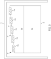
- the plurality of heating cartridges 110a-110e may be arranged in a step-configuration, as depicted in FIG. 9 . This configuration of heating cartridges may be used when the weirs 63 or sidewalls of the trough 61 have an angled configuration as depicted in FIG. 9 .
- the plurality of heating cartridges 110a-110e may be positioned in ports of the housing enclosing the forming vessel 60 and attached to the housing as described herein above with respect to FIGS. 2 and 3 .
- the plurality of heating cartridges 110a-110e may be operated and controlled as described hereinabove with respect to FIGS. 2 and 3 to regulate the temperature of the molten glass proximate the trough 61 of the forming vessel 60 to prevent devitrification of the molten glass in the trough 61 and flowing over the forming body 61.
- FIG. 6 graphically depicts a mathematical model of the root temperature response to individual power changes to heating cartridges comprising molybdenum disilicide heating elements as described herein.
- the model is based on five replaceable heating cartridges (SL1, SL2, SL3, SL4, SL5), each having a heat directing surface 122 oriented at an angle ⁇ of about 135° relative to the bottom surface 126 of the heating cartridge.
- the heating cartridges were modeled as being positioned entirely upstream from the root 70 so as to effectively direct heat onto the root 70.
- the heating cartridges were configured to span across the width of the forming vessel.
- Each heating cartridge in the model was adjusted, one at a time, by 1000W power increments provided to the molybdenum disilicide elements.
- the temperature responses from the 1000W increment power changes in the model were measured in inches from the inlet dam of the forming vessel (i.e., proximate the end 64a of the forming vessel 60 depicted in FIG. 1 .
- the data of FIG. 6 indicates that individual power adjustments to each heating cartridge can provide a managed control of the temperature of localized areas across the width of the root.
- the temperature response of the root due to an incremental power change to a heating cartridge is highest in the localized area of the root closest to the adjusted heating cartridge. As the distance from the adjusted heating cartridge increases, the temperature response of the root decreases as show in FIG. 6 .
- the temperature response at the inlet dam due to the heating cartridge closest to the inlet dam (depicted as curve SL1 in FIG. 6 ) is greatest closest to the inlet dam and degrades with increasing distance from the inlet dam.
- variations in the temperature at the root can be mitigated through the use of multiple heating cartridges spaced across the width of the root.
- the heating cartridges can be spaced such that the effective heating area of each cartridge overlaps with another, thereby mitigating "cool spots" across the width of the root. That is, in FIG. 6 , the temperature response curves SL1-SL5 overlap in the width-wise direction of the root, as indicated by the distance from the inlet dam depicted on the x-axis.
- the data indicates that the plurality of segmented and replaceable heating cartridges as disclosed herein can be easily adjusted to effectively reduce any devitrification of glass drawn across the root.
Landscapes
- Chemical & Material Sciences (AREA)
- Engineering & Computer Science (AREA)
- Materials Engineering (AREA)
- Organic Chemistry (AREA)
- Glass Melting And Manufacturing (AREA)
- Re-Forming, After-Treatment, Cutting And Transporting Of Glass Products (AREA)
- Glass Compositions (AREA)
- Physical Vapour Deposition (AREA)
Description
- The present specification generally relates to methods and apparatuses for making glass ribbons.
- Glass forming apparatuses are commonly used to form various glass products such as glass sheets used for LCD displays and the like. These glass sheets may be manufactured by downwardly flowing molten glass over a forming wedge to form a continuous glass ribbon. Developing technologies are using glass compositions with increasingly lower liquidus viscosities. As such, higher forming temperatures are used to prevent devitrification of molten glass as it traverses the forming wedge.
- Accordingly, a need exists for alternative methods and apparatuses for forming glass ribbons which can provide higher forming temperatures to mitigate devitrification of the glass.
US 2011/126591 A1 ,WO 2013/081827 A1 ,US 2009/217705 A1 ,WO 2015/148631 A1 ,WO 2015/080879 A1 andUS 3506429 A all relate to apparatus for forming a glass ribbon downwardly. - According to the invention, an apparatus for forming a glass ribbon includes a forming wedge disposed in a housing and including a pair of downwardly inclined forming surface portions converging at a root. A plurality of heating cartridges may be positioned in ports of the housing. Each heating cartridge includes a heat directing surface that is oriented at an angle of greater than about 90° with respect to a bottom surface of the heating cartridge, such that the heat directing surface is downward-facing. The heat directing surface includes at least one heating element positioned adjacent to the heat directing surface. The heating cartridge is positioned such that the heat directing surface faces the forming wedge and an upper edge of the heat directing surface is positioned above the root to direct heat from the heat directing surface towards the root of the forming wedge.
- According to another embodiment, a view factor from the heat directing surface may be greater below a top surface of the heating cartridge than above the top surface of the heating cartridge. An upper edge of the heat directing surface and the top surface of the heating cartridge may thermally shield an area above the heat directing surface from an area below the heat directing surface.
- Additional features and advantages of the methods and apparatuses for forming glass ribbons will be set forth in the detailed description which follows, and in part will be readily apparent to those skilled in the art from that description or recognized by practicing the embodiments described herein, including the detailed description which follows the claims, as well as the appended drawings.
- It is to be understood that both the foregoing general description and the following detailed description describe various embodiments and are intended to provide an overview or framework for understanding the nature and character of the claimed subject matter. The accompanying drawings are included to provide a further understanding of the various embodiments, and are incorporated into and constitute a part of this specification. The drawings illustrate the various embodiments described herein, ad together with the description serve to explain the principles and operations of the claimed subject matter.
-
-
FIG. 1 schematically depicts an apparatus for forming a glass ribbon according to one or more embodiments shown and described herein; -
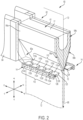
FIG. 2 schematically depicts a cross sectional perspective view at the location of line 3-3 ofFIG. 1 ; -
FIG. 3 schematically depicts a perspective front view of the apparatus for forming a glass ribbon ofFIG. 2 according to one or more embodiments shown and described herein; -
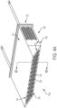
FIG. 4A schematically depicts a replaceable heating cartridge for use in an apparatus for making glass according to one or more embodiments shown and described herein; -
FIG. 4B schematically depicts a cross section of the replaceable heating cartridge alongline 4B-4B ofFIG. 4A ; -
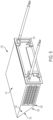
FIG. 5 schematically depicts a perspective back view of the replaceable heating cartridge ofFIG. 4A according to one or more embodiments shown and described herein; -
FIG. 6 graphically depicts a mathematical model of the root temperature response to individual power changes to heating cartridges comprising molybdenum disilicide heating elements as described herein; -
FIG. 7 schematically depicts another embodiment of a forming vessel of glass manufacturing apparatus with heating cartridges disposed proximate the trough of the forming vessel according to one or more embodiments shown and described herein; -
FIG. 8 schematically depicts a cross section, as taken along line 8-8 of the forming vessel ofFIG. 7 according to one or more embodiments shown and described herein; and -
FIG. 9 schematically depicts another embodiment of a forming vessel of glass manufacturing apparatus with heating cartridges disposed proximate the trough of the forming vessel according to one or more embodiments shown and described herein. - Reference will now be made in detail to embodiments of the methods and apparatuses for forming glass ribbons and heating cartridges for use with the same, examples of which are illustrated in the accompanying drawings. Whenever possible, the same reference numerals are used throughout the drawings to refer to the same or like parts. One embodiment of an apparatus for making glass ribbons is shown in
FIG. 1 , and is designated generally throughout by thereference number 10. According to one embodiment, an apparatus for forming a glass ribbon includes a forming wedge disposed in a housing and comprising a pair of downwardly inclined forming surface portions converging at a root. A plurality of heating cartridges may be positioned in ports of the housing. Each heating cartridge includes a heat directing surface that is oriented at an angle of greater than about 90° with respect to a bottom surface of the heating cartridge. The heat directing surface includes a heating element positioned adjacent to the heat directing surface. The heating cartridge is positioned such that the heat directing surface faces the forming wedge and an upper edge of the heat directing surface and a top surface of the heating cartridge are positioned above at least one of the root of the forming wedge. Various embodiments of methods and apparatuses for forming glass ribbons and heating cartridges for use with the same will be described in further detail herein with specific reference to the appended drawings. - Ranges can be expressed herein as from "about" one particular value, and/or to "about" another particular value. When such a range is expressed, another embodiment includes from the one particular value and/or to the other particular value. Similarly, when values are expressed as approximations, by use of the antecedent "about," it will be understood that the particular value forms another embodiment. It will be further understood that the endpoints of each of the ranges are significant both in relation to the other endpoint, and independently of the other endpoint.
- Directional terms as used herein - for example up, down, right, left, front, back, top, bottom - are made only with reference to the figures as drawn and are not intended to imply absolute orientation.
- Unless otherwise expressly stated, it is in no way intended that any method set forth herein be construed as requiring that its steps be performed in a specific order, nor that with any apparatus specific orientations be required. Accordingly, where a method claim does not actually recite an order to be followed by its steps, or that any apparatus claim does not actually recite an order or orientation to individual components, or it is not otherwise specifically stated in the claims or description that the steps are to be limited to a specific order, or that a specific order or orientation to components of an apparatus is not recited, it is in no way intended that an order or orientation be inferred, in any respect. This holds for any possible non-express basis for interpretation, including: matters of logic with respect to arrangement of steps, operational flow, order of components, or orientation of components; plain meaning derived from grammatical organization or punctuation, and; the number or type of embodiments described in the specification.
- As used herein, the singular forms "a," "an" and "the" include plural referents unless the context clearly dictates otherwise. Thus, for example, reference to "a" component includes aspects having two or more such components, unless the context clearly indicates otherwise.
- Referring now to
FIG. 1 , one embodiment of aglass forming apparatus 10 for forming aglass ribbon 12 is schematically depicted. Theglass forming apparatus 10 generally includes amelting vessel 15 configured to receiveglass batch material 16 from astorage bin 18. Theglass batch material 16 can be introduced to themelting vessel 15 by abatch delivery device 20 powered by amotor 22. Anoptional controller 24 may be provided to activate themotor 22 and a moltenglass level probe 28 can be used to measure the glass melt level within astandpipe 30 and communicate the measured information to thecontroller 24. - The
glass forming apparatus 10 includes a fining vessel 38, such as a fining tube, located downstream from themelting vessel 15 and coupled to themelting vessel 15 by way of a first connectingtube 36. A mixing vessel 42, such as a stir chamber, is located downstream from the fining vessel 38. Adelivery vessel 46, such as a bowl, may be located downstream from the mixing vessel 42. As depicted, a second connecting tube 40 couples the fining vessel 38 to the mixing vessel 42 and a third connectingtube 44 couples the mixing vessel 42 to thedelivery vessel 46. As further illustrated, adowncomer 48 is positioned to deliver glass melt from thedelivery vessel 46 to aninlet 50 of a formingvessel 60. - The melting
vessel 15 is typically made from a refractory material, such as refractory (e.g., ceramic) brick. Theglass forming apparatus 10 may further include components that are typically made from platinum or platinum-containing metals such as platinum-rhodium, platinum-iridium and combinations thereof, but which may also comprise such refractory metals such as molybdenum, palladium, rhenium, tantalum, titanium, tungsten, ruthenium, osmium, zirconium, and alloys thereof and/or zirconium dioxide. The platinum-containing components can include one or more of the first connectingtube 36, the fining vessel 38, the second connecting tube 40, thestandpipe 30, the mixing vessel 42, the third connectingtube 44, thedelivery vessel 46, thedowncomer 48 and theinlet 50. The formingvessel 60 can also be made from a refractory material (for example, refractory brick and/or refractory metal) and is designed to form the glass melt into aglass ribbon 12. -
FIG. 2 is a cross sectional perspective view of theglass forming apparatus 10 along line 2-2 ofFIG. 1 . As shown, the formingvessel 60 includes a formingwedge 62 comprising an upwardly (i.e in the +x direction of the coordinate axes depicted inFIG. 2 )open trough 61, a pair of downwardly (i.e., in the -x direction of the coordinate axes depicted inFIG. 2 ) inclined formingsurface portions opposed ends wedge 62. The downwardly inclined formingsurface portions root 70. Adraw plane 72 extends through theroot 70. Theglass ribbon 12 may be drawn from the formingwedge 62 in the downstream direction 68 along thedraw plane 72, as will be described further herein. As depicted, thedraw plane 72 bisects theroot 70 in a generally horizontal, lengthwise direction (the +/-y direction of the coordinate axes depicted inFIG. 2 ) of the formingvessel 60 through theroot 70. However, it should be understood that thedraw plane 72 may extend at other various orientations with respect to theroot 70 other than bisecting the formingvessel 60 through the root. WhileFIGS. 1 and2 generally depict one embodiment of a glass forming apparatus and a forming vessel, it should also be understood that aspects of the present disclosure may be used with various other forming vessel configurations. - Referring to
FIGS. 1 and2 , in certain embodiments, the formingvessel 60 may comprise anedge director surface portions root 70 of the formingvessel 60. In further embodiments, the edge director can intersect with both downwardly inclined formingsurface portions wedge 62. For instance, as shown inFIG. 1 , anedge director wedge 62 with eachedge director surface portions edge director U.S. Pat. Nos. 3,451,798 ,3,537,834 ,7,409,839 ,U.S. Pat. Application No. 14/278582, filed May 15, 2014 U.S. Provisional Pat. Application No. 61/155,669, filed Feb. 26, 2009 - Still referring to
FIG. 1 , theglass forming apparatus 10 can optionally include at least one edge roller assembly (not shown) for drawing glass ribbon from theroot 70 of the formingvessel 60. It should be understood that various edge roller assembly configurations may be used in accordance with aspects of the present disclosure. For example, aspects of the present disclosure may be used with edge roller assembly configurations as disclosed inU.S. Pat. Application No. 14/278582, filed May 15, 2014 - A
housing 14 encloses the formingvessel 60. Thehousing 14 may be formed from steel and contain refractory material and/or insulation to thermally insulate the formingvessel 60, and the molten glass flowing in and around the formingvessel 60, from the surrounding environment. - Referring now to
FIGS. 1-2 , in operation,batch material 16, specifically batch material for forming glass, is fed from thestorage bin 18 into the meltingvessel 15 with thebatch delivery device 20. Thebatch material 16 is melted into molten glass in themelting vessel 15. The molten glass passes from the meltingvessel 15 into the fining vessel 38 through the first connectingtube 36. Dissolved gasses, which may result in glass defects, are removed from the molten glass in the fining vessel 38. The molten glass then passes from the fining vessel 38 into the mixing vessel 42 through the second connecting tube 40. The mixing vessel 42 homogenizes the molten glass, such as by stirring, and the homogenized molten glass passes through the third connectingtube 44 to thedelivery vessel 46. Thedelivery vessel 46 discharges the homogenized molten glass throughdowncomer 48 and into theinlet 50 which, in turn, passes the homogenized molten glass into thetrough 61 of the formingvessel 60. - As
molten glass 17 fills the upwardlyopen trough 61 of formingwedge 62, it overflows thetrough 61 and flows over the inclined formingsurface portions root 70 of the formingwedge 62, thereby forming aglass ribbon 12. As depicted inFIG. 2 , theglass ribbon 12 may be drawn in the downstream direction 68 along thedraw plane 72 that extends through theroot 70. - For glass forming apparatuses as depicted in
FIGS. 1-2 , it has been found that developing technologies such as high performance displays (HPD) utilizing organic light emitting diode (OLED) technology benefit from glass compositions that are difficult to form, such as glass compositions with lower liquidus viscosities. Such glass compositions typically are made with higher forming temperatures to prevent the formation of defects, such as devitrification, in the glass ribbon drawn from the formingvessel 60. The glass forming apparatuses described herein utilize heating cartridges positioned proximate the root of the formingvessel 60 to maintain the molten glass at relatively high forming temperatures thereby aiding the sheet-forming process and preventing the formation of defects in the glass ribbon. - Specifically referring again to
FIGS. 1-3 , to maintain a relatively high temperature of the molten glass in theglass ribbon 12 drawn from theroot 70 of the formingvessel 60, theglass forming apparatus 10 further includes a plurality ofheating cartridges ports 112 formed in thehousing 14 and/or housing seal plate 136 (FIG. 3 ). Thehousing seal plate 136 forms part of housing 14 (FIGS. 1-2 ). As shown inFIG. 3 , a first series ofports 112 and a second series of ports (not shown) are arranged so that a first plurality ofheating cartridges 110 and a second plurality ofheating cartridges 111 are located on opposite sides of theroot 70 such that thedraw plane 72 extends between the first plurality ofheating cartridges 110 and the second plurality ofheating cartridges 111. The first plurality ofheating cartridges 110 and the first series ofports 112 will be described in more detail. However, it should be understood that the first plurality ofheating cartridges 110 and the second plurality ofheating cartridges 111 are substantially identical or of a similar construct to the other. Similarly, it should be understood that each series ofports 112 are substantially identical or of a similar construct to the other. - As depicted in
FIGS. 1-2 , the first series ofports 112 are arrayed across the width (the +/-y direction of the coordinate axes depicted inFIGS. 1 and2 ) of the formingvessel 60 so that the first series ofports 112 spans the width (the +/-y direction of the coordinate axes depicted inFIGS. 1 and2 ) of thedraw plane 72 on which theglass ribbon 12 is drawn. Accordingly, it should be understood that the first plurality ofheating cartridges 110, when inserted in the corresponding ports, are also arrayed across the width of the formingvessel 60 and extend across the width of thedraw plane 72 of theglass ribbon 12. In some embodiments, each port of the first series ofports 112 are spaced laterally (i.e., in the +/-y direction of the coordinate axes depicted inFIGS. 1 and2 ) apart from one another across the width of the forming vessel. In certain embodiments, each port of the first series ofports 112 can be spaced laterally apart from one another by an equal distance. - The first plurality of
heating cartridges 110 may be configured to direct heat onto theroot 70, thereby maintaining theroot 70 at a desired temperature, such as above the divitrification temperature of the molten glass and, in turn, mitigating the formation of defects in the glass. As depicted inFIGS. 2 and3 , the first series ofports 112 can be located in thehousing 14 such that the first plurality ofheating cartridges 110 are positioned adjacent to and spaced from theroot 70 of the formingvessel 60 in the -z direction. In the embodiment depicted inFIG. 3 , the first plurality ofheating cartridges 110 are spaced from theroot 70 in the -z direction, and further positioned such that a portion of eachheating cartridge 110 is located above (the +x direction of the coordinate axes) theroot 70 and a portion is located below (in the -x direction of the coordinate axes) theroot 70. Alternatively, in the embodiment depicted inFIG. 1 , the first series ofports 112 can be located in thehousing 14 such that the firstplurality heating cartridges 110 are positioned entirely above theroot 70. In still other embodiments (not shown), the first series ofports 112 can be located in thehousing 14 such that the firstplurality heating cartridges 110 are positioned below theroot 70. -
FIGS. 1-3 depict a first plurality ofheating cartridges 110 that includes fiveheating cartridges FIGS. 1-3 depict that these five heating cartridges are positioned in a first series ofports 112 that includes fiveports housing 14. However, it should be understood that this is an exemplary number and that the number of heating cartridges in the first plurality ofheating cartridges 110 and the number of corresponding ports in the first series ofports 112 may be more than five or less than five. Likewise, the width of the heating cartridges depends on the number of heating cartridges utilized as well as the width of the forming vessel. For example,FIG. 1 illustrates five heating cartridges across the full width of the forming vessel, while FIGS. 23 illustrate five heating cartridges across less than the full width of the forming vessel. One of the first plurality ofheating cartridges 110 will be described in more detail herein. However, it should be understood that eachheating cartridge heating cartridges 110, as well as each heating cartridge of the second plurality ofheating cartridges 111, is substantially identical or of a similar construct.. - Referring now to
FIGS. 3-5 , in embodiments, each of the first plurality ofheating cartridges 110 includes anenclosure 120 having aheat directing surface 122 with at least oneheating element 124 positioned on or adjacent to the face thereof. Theenclosure 120 may be fabricated from a variety of materials suitable for use at the elevated temperature conditions associated with theglass forming apparatus 10. For example, theenclosure 120, and other portions of theheating cartridge 110a can be formed from a refractory material such as high temperature nickel-based alloys, steel (e.g., stainless steel), or other alloys or materials (or combinations of materials), to meet the structural and/or thermal parameters associated with theglass forming apparatus 10. For example, in one embodiment, theenclosure 120 may be made of nickel-based alloys, such as Haynes® 214® nickel-based alloy produced by Haynes International, Inc. - While
FIGS. 3-5 depict theheating cartridge 110a as comprising an enclosure, it should be understood that other embodiments are contemplated and possible. For example, rather than including aseparate enclosure 120, theheat directing surface 122 may be affixed to a block (or blocks) of refractory materials instead of having a separate enclosure formed from metals/alloys. For example and without limitation, in embodiments, the heat directing surface is affixed to a body formed from NA-33 refractory blocks produced by ANH refractories. - In one embodiment, the
heat directing surface 122 of theheating cartridge 110a is formed from a ceramic refractory backer material with low emissivity. Suitable ceramic refractory materials include, without limitation, SALI board available from Zircar ceramics. Portions of theheating cartridge 110a which are not directly exposed to the high temperatures of theglass forming apparatus 10 may be made from materials suitable for lower temperature applications. For example, when theheating cartridge 110a comprises an enclosure, theback face 125 of theenclosure 120 may be made from stainless steel selected to meet the structural and/or thermal parameters associated with theglass forming apparatus 10, such as, for example, 420 stainless steel. - In the embodiments described herein, the
heat directing surface 122 of theheating cartridge 110a is oriented at an angle α with respect to abottom surface 126 of theheating cartridge 110a In the embodiments described herein, the angle α is greater than 90°. For example, in certain embodiments, the angle α of theheat directing surface 122 may be from about 120° to about 150° relative to thebottom surface 126 of theheating cartridge 110a. In other embodiments, the angle α of theheat directing surface 122 may be from about 130° to about 140° relative to thebottom surface 126 of theheating cartridge 110a. In specific embodiments, the angle α of theheat directing surface 122 is about 135° relative to thebottom surface 126 of theheating cartridge 110a. - In some embodiments, the downward-facing orientation of the
heat directing surface 122 facilitates positioning theheating cartridge 110a in thehousing 14 of theglass forming apparatus 10 such that theheat directing surface 122 of each replaceable heating cartridge faces theroot 70 of the formingvessel 60. Specifically, the downward facing orientation of theheat directing surface 122 enables theheat directing surface 122 to radiate and direct heat toward and onto theroot 70 of the formingvessel 60 with only minimal loss of heat to the surrounding environment, particularly to areas above theroot 70, such as areas above the heating cartridge. - Referring again to
FIGS. 1-3 , in some embodiments, theheating cartridge 110a is positioned in thehousing 14 of theglass forming apparatus 10 such that theupper edge 123 of theheat directing surface 122 and thetop surface 127 of eachheating cartridge 110a are positioned above theroot 70. This positioning enables theheat directing surface 122 of theheating cartridge 110a to direct heat towards and onto theroot 70 of the formingvessel 60, thereby increasing the temperature of theroot 70 as well as the temperature of the molten glass flowing over the formingvessel 60 in the area of theroot 70. For instance, as depicted inFIG. 1 , theheating cartridge 110a can be positioned entirely upstream from theroot 70. In alternative embodiments, as depicted inFIG. 3 , theheating cartridge 110a can be positioned partially upstream from theroot 70. For example, thetop surface 127 of theheating cartridge 110a, can be positioned upstream from theroot 70 while thebottom surface 126 of theheating cartridge 110a is positioned downstream from theroot 70. Positioning theheating cartridge 110a partially upstream from theroot 70 may provide adequate heating to theroot 70 to prevent devitrification of the molten glass while reducing heat loss to non-target areas above theroot 70 due to the angled heat directing face of the heating cartridge. Further, positioning theheating cartridge 110a partially upstream from theroot 70 may allow the heating cartridge, specifically theheat directing surface 122, to be positioned closer to theroot 70 such that a greater amount of heat is incident on theroot 70 and the molten glass flowing over theroot 70. - More specifically, the angle of the
heat directing surface 122 and the position of theheating cartridge 110a within thehousing 14 is such that the view factor from the heat directing surface is greater for objects (such as theroot 70 of the forming vessel 60) located below thetop surface 127 of theheating cartridge 110a than objects located above thetop surface 127 of theheating cartridge 110a. The term "view factor," as used herein, refers to the relative proportion of thermal radiation from theheat directing surface 122 which is incident on the specified surface. For example, because the view factor from theheat directing surface 122 is greater for objects (such as theroot 70 of the forming vessel 60) located below thetop surface 127 of theheating cartridge 110a than objects located above thetop surface 127 of theheating cartridge 110a, objects located below thetop surface 127 of theheating cartridge 110a will receive a greater amount of heat flux from theheat directing surface 122 of theheating cartridge 110a than objects located above thetop surface 127 of theheating cartridge 110a. - In some other embodiments (not shown), the
heating cartridge 110 may be positioned downstream of the root 70 (i.e., in the -x direction). In these embodiments, the heat directing face of the heating cartridge may be angled to direct heat towards theroot 70 as the heat rises along the angled heat directing face. - In the embodiments described herein, it should be understood that the
heating cartridge 110a can function as both a heater for heating theroot 70 as well as a thermal shield to thermally isolate and shield the area above theheating cartridge 110a from an area below theheating cartridge 110a, thereby preventing the loss of heat from theroot 70 and molten glass flowing over theroot 70 to non-target areas located above of theroot 70 of the formingvessel 60. Specifically, as described above, theheat directing surface 122 of theheating cartridge 110a is oriented at an angle α that is greater than 90° with respect to thebottom surface 126 of theheating cartridge 110a. As such, thetop surface 127 of theheating cartridge 110a and theupper edge 123 of theheat directing surface 122 are cantilevered over thelower edge 129 andbottom surface 126 of theheating cartridge 110a. This arrangement of theheat directing surface 122 creates the view factor of the heating cartridge as described herein. In addition, the cantilevered arrangement of theheat directing surface 122 extends theheat directing surface 122 across agap 170 between theheat directing surface 122 and the formingvessel 60, decreasing the spacing between the formingvessel 60 and the heating cartridges and slowing the loss of heat from areas downstream of the root to areas of theglass forming apparatus 10 located upstream of theroot 70 of the formingvessel 60. As such, theheating cartridge 110a also thermally shields areas above theheat directing surface 122 from areas below theheat directing surface 122. - Still referring to
FIGS. 4-5 , theheating element 124 positioned on or adjacent to theheat directing surface 122 is a resistance heating element. In certain embodiments, the material of the resistance heating element can be molybdenum disilicide. In some embodiments, theheating element 124 may be constructed from wire formed from molybdenum disilicide. For example and without limitation, in one embodiment theheating element 124 may be constructed from a molybdenum disilicide wire that is positioned on theheat directing surface 122 in a serpentine shape. By way of example and not limitation, aheating element 124 formed from molybdenum disilicide can include a winding element positioned on theheat directing surface 122. The ends of theheating element 124 extending through theheating cartridge 110a may have a diameter selected to minimize power losses away from theheat directing surface 122. - It has been determined that forming heating cartridge as described herein can greatly improve the heating efficiency of the heating cartridge. This may be attributable to the increased power-carrying capacity of the molybdenum disilicide heating element compared to other materials as well as the additional refractory material insulation and the angled heat directing surface. Further, it has also been found that the combination of segmented heating cartridges, such as the heating cartridges described herein, and molybdenum disilicide heating elements allows for higher forming temperatures at the
root 70 than other conventional heating element materials. This enables, for example, the use of higher forming temperatures which, in turn, prevents devitrification of molten glass and mitigates defects in the glass ribbon drawn from theroot 70 of the formingvessel 60. Additionally, with forming temperatures at theroot 70 being equal, molybdenum disilicide heating elements advantageously achieve such forming temperatures with lower power input than used with conventional heating element materials. - While
FIG. 4A depicts asingle heating element 124 positioned on theheat directing surface 122 of theheating cartridge 110a, it should be understood that other configurations are contemplated and possible. For example, in some embodiments, theheating element 124 may be a segmented heating element which includes two or more separate heating elements, each of which may be separately powered and controlled. This allows theheat directing surface 122 of theheating cartridge 110a to be formed with individual heating zones which may be independently controlled, thereby providing more refined control of the temperature profile of theheat directing surface 122. - Still referring to
FIGS. 4-5 , located behind the face of theheat directing surface 122 are one or more blocks ofrefractory material 128 which insulate theheat directing surface 122 from the balance of theheating cartridge 110a. These blocks ofrefractory material 128 may be located within anenclosure 120 as depicted inFIGS. 4 and5 or, alternatively, attached directly to theheat directing surface 122 without an enclosure. In certain embodiments therefractory materials 128 are oriented to minimize heat transfer from theheat directing surface 122. Specifically, in certain embodiments, therefractory materials 128 are oriented in alternating vertical stacks and horizontal stacks, as it is believed that alternating vertical stacks and horizontal stacks ofrefractory material 128 may assist in reducing heat at seams between the blocks. In certain embodiments, therefractory material 128 can be oriented at an angle approximately equal to the angle of theheat directing surface 122. In still other embodiments, such as where theheat directing surface 122 is formed from a refractory material such as SALI board or the like, the refractory material of theheat directing surface 122 may extend into the enclosure. In the embodiments described herein, therefractory material 128 may be commercially available refractory materials including, without limitation, SALI board, Insulating Fire Brick (IFB), DuraBoard® 3000 and/or DuraBoard® 2600. In certain embodiments, the refractory blocks may have a first layer closest to theheat directing surface 122 formed from SALI board and a second layer located behind the first layer formed from IFB. - A variety of attachment structures may be used to mount the
heating cartridge 110a with respect to theroot 70. In some embodiments, theheating cartridge 110a may be mounted on abracket 114 engaged with thehousing 14 and/or thehousing seal plate 136, as depicted inFIG 3 . Additionally or alternatively, theheating cartridge 110a can rest on T-wall support brackets 116 that are attached tohousing 14 and/or thehousing seal plate 136, as depicted inFIG 2 . In some embodiments, each of the heating cartridges is removably mounted in the ports of thehousing 14 of theglass forming apparatus 10. Each individual heating cartridge can be independently controlled so that using the plurality of heating cartridges one can reach a desired temperature distribution across the root of the forming wedge. Moreover, the separate nature of each heating cartridge minimizes the impact of a failed heating element and/or the replacement of a heating cartridge. That is, in the event that a single heating element fails during operation, the failure of that heating element results in the loss of only a fraction of the total heating. Moreover, because the heating cartridges are separately controlled, the adjacent heating cartridges may be individually adjusted to offset the loss of heating from a failed heating element. Further, the modular nature of the heating cartridges means that replacement of an individual cartridge impacts only a fraction of the total heating provided, thereby reducing production losses. - In certain embodiments, the apparatus may further include a
controller 180 configured to control heating associated with the plurality of heating cartridges 110,111. In certain embodiments thecontroller 180 may be operably connected to each heating cartridge of the plurality of heating cartridges 110,111, as depicted inFIG 1 . In certain embodiments, control of individual ones of the plurality of heating cartridges 110,111 can be segmented. The term "segmented," as used herein, refers to the ability to independently control and adjust the temperature of each individual heating cartridge in order to provide managed control of the temperature of the glass ribbon during manufacture. The controller may include a processor and memory storing computer readable and executable instructions which, when executed by the processor, individually regulates the power to each heating cartridge, thereby individually increasing or decreasing the heat provided by each heating cartridge based on temperature feedback or other process parameters. Thus, thecontroller 180 may be used to differentially regulate the power that is provided to each heating cartridge of the plurality of heating cartridges 110,111 that span the width of theroot 70 and the width of thedraw plane 72 of theglass ribbon 12. - In certain embodiments, the
controller 180 can be configured to individually operate each heating cartridge of the plurality of heating cartridges 110,111 based on thermal feedback from the glass forming apparatus. For example, in one embodiment thecontroller 180 is configured to obtain thermal feedback from athermal sensor 182, as depicted inFIG. 1 . The feedback obtained by the thermal sensor can be used by thecontroller 180 to individually adjust each heating cartridge of the plurality of heating cartridges 110,111 in order to provide managed control of a thermal characteristic of the apparatus as the manufacture of glass ribbon proceeds. The thermal characteristic can include, for example, the temperature and/or heat loss associated with: a portion of the glass forming apparatus, such as theheat directing surface 122 of each heating cartridge of the plurality of heating cartridges 110,111; a portion of theedge directors vessel 60; portions of the molten glass; and/or other features of theglass forming apparatus 10. - In one embodiment, the
thermal sensor 182 may detect a temperature above a target level and thecontroller 180 may reduce power to at least one heating cartridge of the plurality of heating cartridges 110,111 such that less heat is transferred to the target area, thereby reducing the temperature until the target level temperature is obtained. Alternatively, in certain embodiments thethermal sensor 182 may detect a temperature below a target level, wherein thecontroller 180 may increase power to at least one heating cartridge of the plurality of heating cartridges 110,111, such that more heat is transferred to the target area, thereby increasing the temperature until the target level temperature is obtained. - Referring again to
FIG. 2 , typically, more heat is lost to the surrounding environment on the two outer ends (in the width-wise direction of the forming vessel, i.e., +/- y direction) of thedraw plane 72 of theglass ribbon 12 than is lost to the surrounding environment in the middle of thedraw plane 72. As such, thecontroller 180 may provide more power and heat to the heating cartridges of the plurality ofheating cartridges FIG. 2 ) of thedraw plane 72 of theglass ribbon 12 than to the heating cartridges located in the middle of thedraw plane 72 to compensate for both the heat lost in these areas as well as to account for the greater thickness of glass proximate the edges of thedraw plane 72. - In certain embodiments, the controller can be configured to individually operate each heating cartridge of the plurality of
heating cartridges glass forming apparatus 10. For example, in one embodiment the controller is configured to obtain thermal feedback from at least one thermal sensor (not shown) positioned proximate to theroot 70 of the formingvessel 60. The feedback obtained by the at least one thermal sensor can be used by the controller to individually adjust each heating cartridge of the plurality ofheating cartridges glass forming apparatus 10, such as theheat directing surface 122 of a heating cartridge 1 10a; theroot 70; a portion of the end of the formingvessel 60; portions of the molten glass; and/or other features of theglass forming apparatus 10. - In one embodiment, the at least one thermal sensor may detect a temperature above a target level and the controller may individually reduce power to at least one of heating cartridges of the plurality of
heating cartridges heating cartridges - While
FIGS. 1-3 schematically depict one embodiment of aglass forming apparatus 10 in whichheating cartridges 110a-110e are positioned proximate aroot 70 of the formingwedge 62, it should be understood that other embodiments are contemplated and possible. Referring toFIGS. 4A-4B ,5 ,7 , and8 by way of example, in one embodiment the plurality of heating cartridges may be positioned proximate thetrough 61 of the formingvessel 60. Specifically, the formingvessel 60 is positioned in a housing (not shown) and may include atrough 61 for receiving molten glass and a pair of downwardly inclined formingsurface portions root 70, as described hereinabove. A plurality ofheating cartridges 110a-110e may be removably positioned in ports formed in the housing, as described hereinabove, such that aheat directing surface 122 of each of the heating cartridges faces the formingvessel 60 and anupper edge 123 of theheat directing surface 122 and atop surface 127 of the heating cartridge are positioned above thetrough 61 of the formingvessel 60 to direct heat from theheat directing surface 122 of the heating cartridge towards thetrough 61 of the formingvessel 60, thereby heating the glass at the top of theweirs 63 of thetrough 61 of the formingvessel 60 and preventing devitrification. - More specifically, in these embodiments, each heating cartridge may have substantially the same structure as shown and described herein with respect to
FIGS. 4A-4B and5 . In these embodiments, the angle α of theheat directing surface 122 of theheating cartridge 110a with respect to abottom surface 126 of theheating cartridge 110a may also be greater than or equal to 90°. For example, in certain embodiments, the angle α of theheat directing surface 122 may be from about 120° to about 150° relative to thebottom surface 126 of theheating cartridge 110a. In other embodiments, the angle α of theheat directing surface 122 may be from about 130° to about 140° relative to thebottom surface 126 of theheating cartridge 110a. In specific embodiments, the angle α of theheat directing surface 122 is about 135° relative to thebottom surface 126 of theheating cartridge 110a. - In some embodiments, the
heating cartridges 110a-110e may be positioned at an elevation relative to the formingvessel 60 such that alower edge 129 of the heat directing surface and thebottom surface 126 of the heating cartridge are positioned below the top of theweirs 63. In these embodiments, the angle α of theheat directing surface 122 of theheating cartridge 110a with respect to abottom surface 126 of theheating cartridge 110a may be greater than or equal to 90° such that heat from the heating cartridge is directed towards thetrough 61 of the formingvessel 60. In some other embodiments, theheating cartridges 110a-110e may be positioned at an elevation relative to the formingvessel 60 such that alower edge 129 of the heat directing surface and thebottom surface 126 of the heating cartridge are positioned above thetrough 61. In these embodiments, the angle α of theheat directing surface 122 of theheating cartridge 110a with respect to abottom surface 126 of theheating cartridge 110a may be greater than 90° such that heat from the heating cartridge is directed downward, towards thetrough 61 of the formingvessel 60. - In embodiments, the
heating cartridges 110a-110e may be arranged across the width of the formingvessel 60 as depicted inFIG. 7 . In some embodiments, each of the heating cartridges in the plurality ofheating cartridges 110a-110e are positioned at substantially the same elevation in the +/- X-direction. However, in some embodiments, the plurality ofheating cartridges 110a-110e may be arranged in a step-configuration, as depicted inFIG. 9 . This configuration of heating cartridges may be used when theweirs 63 or sidewalls of thetrough 61 have an angled configuration as depicted inFIG. 9 . - In embodiments where the plurality of
heating cartridges 110a-110e are positioned proximate thetrough 61 of the formingvessel 60, the plurality ofheating cartridges 110a-110e may be positioned in ports of the housing enclosing the formingvessel 60 and attached to the housing as described herein above with respect toFIGS. 2 and3 . In addition, the plurality ofheating cartridges 110a-110e may be operated and controlled as described hereinabove with respect toFIGS. 2 and3 to regulate the temperature of the molten glass proximate thetrough 61 of the formingvessel 60 to prevent devitrification of the molten glass in thetrough 61 and flowing over the formingbody 61. - The embodiments described herein will be further clarified by the following example.
-
FIG. 6 graphically depicts a mathematical model of the root temperature response to individual power changes to heating cartridges comprising molybdenum disilicide heating elements as described herein. The model is based on five replaceable heating cartridges (SL1, SL2, SL3, SL4, SL5), each having aheat directing surface 122 oriented at an angle α of about 135° relative to thebottom surface 126 of the heating cartridge. The heating cartridges were modeled as being positioned entirely upstream from theroot 70 so as to effectively direct heat onto theroot 70. The heating cartridges were configured to span across the width of the forming vessel. Each heating cartridge in the model was adjusted, one at a time, by 1000W power increments provided to the molybdenum disilicide elements. The temperature responses from the 1000W increment power changes in the model were measured in inches from the inlet dam of the forming vessel (i.e., proximate theend 64a of the formingvessel 60 depicted inFIG. 1 . - The data of
FIG. 6 indicates that individual power adjustments to each heating cartridge can provide a managed control of the temperature of localized areas across the width of the root. The temperature response of the root due to an incremental power change to a heating cartridge is highest in the localized area of the root closest to the adjusted heating cartridge. As the distance from the adjusted heating cartridge increases, the temperature response of the root decreases as show inFIG. 6 . For example, the temperature response at the inlet dam due to the heating cartridge closest to the inlet dam (depicted as curve SL1 inFIG. 6 ) is greatest closest to the inlet dam and degrades with increasing distance from the inlet dam. Further, as shown inFIG. 6 , variations in the temperature at the root can be mitigated through the use of multiple heating cartridges spaced across the width of the root. For example, as shown inFIG. 6 , the heating cartridges can be spaced such that the effective heating area of each cartridge overlaps with another, thereby mitigating "cool spots" across the width of the root. That is, inFIG. 6 , the temperature response curves SL1-SL5 overlap in the width-wise direction of the root, as indicated by the distance from the inlet dam depicted on the x-axis. This demonstrates that any thickness impact or temperature deviation that occurs across an area of root of the forming vessel can be easily corrected by individually adjusting/controlling the power to the heating cartridge that is correspondingly located in that area. Thus, the data indicates that the plurality of segmented and replaceable heating cartridges as disclosed herein can be easily adjusted to effectively reduce any devitrification of glass drawn across the root.
Claims (7)
- An apparatus (10) for forming a glass ribbon comprising:a forming wedge (62) comprising a pair of downwardly inclined forming surface portions (66a, 66b) converging at a root (70);a housing (14) enclosing the forming wedge (62); anda heating cartridges (110) , the heating cartridge (110) comprising a heat directing surface (122) that is oriented at an angle of greater than 90° with respect to a bottom surface (126) of the heating cartridge (110) such that the heat directing surface (122) is downward-facing, the heat directing surface (122) comprising at least one heating element (124) positioned adjacent to the heat directing surface (122), wherein the heating cartridge (110) is positioned such that the heat directing surface (122) faces the forming wedge (62), and an upper edge (123) of the heat directing surface (122) and a top surface (127) of the heating cartridge (110) are positioned above the root (70) to direct heat from the heat directing surface (122) of the heating cartridge (110) towards the root (70) of the forming wedge (62).
- The apparatus (10) of claim 1, wherein the angle of the heat directing surface (122) is from 120° to 150° relative to the bottom surface (126) of the heating cartridge (110).
- The apparatus (10) of claim 1, wherein the angle of the heat directing surface (122) is from 130° to 140° relative to the bottom surface (126) of the heating cartridge (110).
- The apparatus (10) of any one of claims 1-3, further comprising a plurality of heating cartridges (111), wherein the plurality of heating cartridges (111) are arrayed across a width of the forming wedge (62).
- The apparatus (10) of any one of claims 1-4, wherein a lower edge (129) of the heat directing surface (122) and the bottom surface (126) of the heating cartridge (110) are positioned below the root (70).
- The apparatus (10) of any one of claims 1-5, wherein a view factor from the heat directing surface (122) of the heating cartridge (110) is greater below a top surface (127) of the heating cartridge (110) than above the top surface (127) of the heating cartridge (110), and an upper edge (123) of the heat directing surface (122) and the top surface (127) of the heating cartridge (110) thermally shield an area above the heat directing surface (122) from an area below the heat directing surface (122).
- The apparatus (10) of any one of claims 1-6, wherein the at least one heating element (124) comprises molybdenum disilicide.
Applications Claiming Priority (3)
| Application Number | Priority Date | Filing Date | Title |
|---|---|---|---|
| US201562257078P | 2015-11-18 | 2015-11-18 | |
| US201662331762P | 2016-05-04 | 2016-05-04 | |
| PCT/US2016/060480 WO2017087183A2 (en) | 2015-11-18 | 2016-11-04 | Methods and apparatuses for forming glass ribbons |
Publications (2)
| Publication Number | Publication Date |
|---|---|
| EP3377452A2 EP3377452A2 (en) | 2018-09-26 |
| EP3377452B1 true EP3377452B1 (en) | 2023-05-10 |
Family
ID=57485863
Family Applications (1)
| Application Number | Title | Priority Date | Filing Date |
|---|---|---|---|
| EP16806320.4A Active EP3377452B1 (en) | 2015-11-18 | 2016-11-04 | Method and apparatuses for forming glass ribbons |
Country Status (7)
| Country | Link |
|---|---|
| US (1) | US11465926B2 (en) |
| EP (1) | EP3377452B1 (en) |
| JP (3) | JP6912472B2 (en) |
| KR (1) | KR102633704B1 (en) |
| CN (1) | CN108349770B (en) |
| TW (1) | TWI737646B (en) |
| WO (1) | WO2017087183A2 (en) |
Families Citing this family (12)
| Publication number | Priority date | Publication date | Assignee | Title |
|---|---|---|---|---|
| EP3753908A1 (en) * | 2016-08-24 | 2020-12-23 | Corning Incorporated | Method of controlling a flowrate of molten material in a glass manufacturing process |
| TWI774715B (en) * | 2016-12-21 | 2022-08-21 | 美商康寧公司 | Method and apparatus for managing glass ribbon cooling |
| CN121698557A (en) | 2017-04-24 | 2026-03-20 | 康宁股份有限公司 | Fusion draw apparatus and method of making glass ribbon |
| KR20200078677A (en) | 2017-11-22 | 2020-07-01 | 코닝 인코포레이티드 | Apparatus comprising edge directors for forming glass ribbons |
| WO2019108593A1 (en) * | 2017-11-29 | 2019-06-06 | Corning Incorporated | Glass manufacturing apparatus and methods including a thermal shield |
| WO2020005555A1 (en) | 2018-06-28 | 2020-01-02 | Corning Incorporated | Continuous methods of making glass ribbon and as-drawn glass articles from the same |
| JP7403959B2 (en) * | 2019-03-12 | 2023-12-25 | 日東電工株式会社 | inductor |
| DE102019120065A1 (en) | 2019-07-24 | 2021-01-28 | Schott Ag | Device and method for producing glass ribbons |
| DE102019120064A1 (en) * | 2019-07-24 | 2021-01-28 | Schott Ag | Device and method for producing glass ribbons |
| JP2022547308A (en) * | 2019-09-13 | 2022-11-11 | コーニング インコーポレイテッド | A continuous method for forming a glass ribbon using a gyrotron microwave heating device |
| US12384711B2 (en) | 2020-02-03 | 2025-08-12 | Corning Incorporated | Methods and apparatus for manufacturing a glass ribbon |
| JP2023531448A (en) * | 2020-06-19 | 2023-07-24 | コーニング インコーポレイテッド | Glass ribbon manufacturing method |
Family Cites Families (26)
| Publication number | Priority date | Publication date | Assignee | Title |
|---|---|---|---|---|
| US1781452A (en) * | 1922-03-20 | 1930-11-11 | Libbey Owens Ford Glass Co | Method and apparatus for drawing sheet glass |
| US1891373A (en) * | 1931-06-11 | 1932-12-20 | Danner Edward | Glass forming method and apparatus |
| GB1054322A (en) | 1962-10-31 | 1967-01-11 | Glaverbel | Improvements in or relating to the manufactures of sheet glass |
| US3451798A (en) | 1966-04-04 | 1969-06-24 | Corning Glass Works | Sheet glass edge control device |
| US3506429A (en) * | 1967-01-03 | 1970-04-14 | Corning Glass Works | Apparatus for improving thickness uniformity in down drawn glass sheet |
| US3537834A (en) | 1968-08-07 | 1970-11-03 | Corning Glass Works | Maintaining sheet glass width |
| BE757057A (en) | 1969-10-06 | 1971-04-05 | Corning Glass Works | METHOD AND APPARATUS FOR CHECKING THE THICKNESS OF A NEWLY STRETCHED SHEET OF GLASS |
| US5709723A (en) * | 1995-08-21 | 1998-01-20 | Eastman Kodak Company | Method for producing large glass preforms |
| US7409839B2 (en) | 2005-04-29 | 2008-08-12 | Corning Incorporated | Method and apparatus for making a glass sheet |
| EP1746076A1 (en) * | 2005-07-21 | 2007-01-24 | Corning Incorporated | Method of making a glass sheet using rapid cooling |
| JP5281569B2 (en) | 2006-04-28 | 2013-09-04 | コーニング インコーポレイテッド | Apparatus and method for forming glass substrate with increased edge stability |
| TWI391335B (en) * | 2007-05-18 | 2013-04-01 | Corning Inc | Method and apparatus for minimizing inclusions in a glass making process |
| US20090217705A1 (en) | 2008-02-29 | 2009-09-03 | Filippov Andrey V | Temperature control of glass fusion by electromagnetic radiation |
| CN102369166B (en) | 2009-02-26 | 2014-11-26 | 康宁股份有限公司 | Apparatus for forming glass with edge directors and methods |
| US8490432B2 (en) | 2009-11-30 | 2013-07-23 | Corning Incorporated | Method and apparatus for making a glass sheet with controlled heating |
| US8707737B2 (en) * | 2009-11-30 | 2014-04-29 | Corning Incorporated | Method and apparatus for pressure control of glass-making thickness-control zone |
| US9227295B2 (en) * | 2011-05-27 | 2016-01-05 | Corning Incorporated | Non-polished glass wafer, thinning system and method for using the non-polished glass wafer to thin a semiconductor wafer |
| US9090505B2 (en) * | 2011-07-15 | 2015-07-28 | Corning Incorporated | Microwave-based glass laminate fabrication |
| JP6165161B2 (en) | 2011-11-28 | 2017-07-19 | コーニング インコーポレイテッド | Downdraw apparatus and method for providing a clean glass manufacturing environment |
| JP5994992B2 (en) | 2012-12-20 | 2016-09-21 | 日本電気硝子株式会社 | Sheet glass manufacturing apparatus and sheet glass manufacturing method |
| US9914657B2 (en) * | 2013-04-30 | 2018-03-13 | Corning Incorporated | Apparatus and method for thermal profile control in an isopipe |
| KR20160090324A (en) * | 2013-11-26 | 2016-07-29 | 코닝 인코포레이티드 | Glass manufacturing apparatus and methods of fabricating glass ribbon |
| JP2017514778A (en) | 2014-03-27 | 2017-06-08 | コーニング インコーポレイテッド | Ceramic oxide body, method for producing the same, and method for producing glass sheet |
| US9512025B2 (en) | 2014-05-15 | 2016-12-06 | Corning Incorporated | Methods and apparatuses for reducing heat loss from edge directors |
| JP2017537048A (en) * | 2014-10-29 | 2017-12-14 | コーニング インコーポレイテッド | Apparatus and method for forming or forming a heated glass sheet |
| US9758418B1 (en) * | 2016-04-06 | 2017-09-12 | Corning Incorporated | Methods of producing glass ribbon |
-
2016
- 2016-11-04 CN CN201680067699.0A patent/CN108349770B/en active Active
- 2016-11-04 JP JP2018525666A patent/JP6912472B2/en active Active
- 2016-11-04 US US15/776,444 patent/US11465926B2/en active Active
- 2016-11-04 EP EP16806320.4A patent/EP3377452B1/en active Active
- 2016-11-04 WO PCT/US2016/060480 patent/WO2017087183A2/en not_active Ceased
- 2016-11-04 KR KR1020187017086A patent/KR102633704B1/en active Active
- 2016-11-08 TW TW105136199A patent/TWI737646B/en active
-
2021
- 2021-07-08 JP JP2021113390A patent/JP7225323B2/en active Active
-
2022
- 2022-10-20 JP JP2022168163A patent/JP2023002691A/en not_active Ceased
Also Published As
| Publication number | Publication date |
|---|---|
| JP2021169407A (en) | 2021-10-28 |
| TWI737646B (en) | 2021-09-01 |
| JP7225323B2 (en) | 2023-02-20 |
| KR102633704B1 (en) | 2024-02-05 |
| TW201720764A (en) | 2017-06-16 |
| KR20180081803A (en) | 2018-07-17 |
| CN108349770B (en) | 2021-07-30 |
| CN108349770A (en) | 2018-07-31 |
| US20200270161A1 (en) | 2020-08-27 |
| JP2018534231A (en) | 2018-11-22 |
| WO2017087183A3 (en) | 2017-07-06 |
| WO2017087183A2 (en) | 2017-05-26 |
| JP6912472B2 (en) | 2021-08-04 |
| JP2023002691A (en) | 2023-01-10 |
| US11465926B2 (en) | 2022-10-11 |
| EP3377452A2 (en) | 2018-09-26 |
Similar Documents
| Publication | Publication Date | Title |
|---|---|---|
| US11465926B2 (en) | Method and apparatuses for forming glass ribbons | |
| US9643874B2 (en) | Methods and apparatuses for reducing heat loss from edge directors | |
| KR101808962B1 (en) | Apparatus for use in direct resistance heating of platinum-containing vessels | |
| US20180370836A1 (en) | Glass manufacturing apparatus with cooling devices and method of using the same | |
| US11242275B2 (en) | Apparatus to control glass flow into glass forming machines | |
| WO2014099560A1 (en) | Method and apparatus for minimizing devitrification on edge directors with induction heating | |
| JP7085546B2 (en) | Methods and equipment for compensating for dimensional fluctuations in the molding body | |
| TW201522254A (en) | Glass manufacturing apparatus and methods of fabricating glass ribbon | |
| JP4581877B2 (en) | Method of energizing and heating a depressurization defoaming tank of a depressurization defoaming device, method of energizing and heating a depressurization defoaming device, and depressurization defoaming method, glass manufacturing method, and depressurization defoaming device using them | |
| CN111433161B (en) | Glass manufacturing apparatus and method including thermal shield | |
| US20200199004A1 (en) | Enclosures for glass forming apparatuses | |
| JP7801375B2 (en) | Apparatus and method for cooling the wall of a glass melting vessel | |
| WO2019195632A1 (en) | Apparatus for heating molten material | |
| KR20260002758A (en) | Melting machine for glass forming equipment | |
| US20220356105A1 (en) | Glass forming devices and methods | |
| JPH08133746A (en) | Electric fusion furnace for glass |
Legal Events
| Date | Code | Title | Description |
|---|---|---|---|
| STAA | Information on the status of an ep patent application or granted ep patent |
Free format text: STATUS: UNKNOWN |
|
| STAA | Information on the status of an ep patent application or granted ep patent |
Free format text: STATUS: THE INTERNATIONAL PUBLICATION HAS BEEN MADE |
|
| PUAI | Public reference made under article 153(3) epc to a published international application that has entered the european phase |
Free format text: ORIGINAL CODE: 0009012 |
|
| STAA | Information on the status of an ep patent application or granted ep patent |
Free format text: STATUS: REQUEST FOR EXAMINATION WAS MADE |
|
| 17P | Request for examination filed |
Effective date: 20180607 |
|
| AK | Designated contracting states |
Kind code of ref document: A2 Designated state(s): AL AT BE BG CH CY CZ DE DK EE ES FI FR GB GR HR HU IE IS IT LI LT LU LV MC MK MT NL NO PL PT RO RS SE SI SK SM TR |
|
| AX | Request for extension of the european patent |
Extension state: BA ME |
|
| DAV | Request for validation of the european patent (deleted) | ||
| DAX | Request for extension of the european patent (deleted) | ||
| STAA | Information on the status of an ep patent application or granted ep patent |
Free format text: STATUS: EXAMINATION IS IN PROGRESS |
|
| 17Q | First examination report despatched |
Effective date: 20201209 |
|
| GRAP | Despatch of communication of intention to grant a patent |
Free format text: ORIGINAL CODE: EPIDOSNIGR1 |
|
| STAA | Information on the status of an ep patent application or granted ep patent |
Free format text: STATUS: GRANT OF PATENT IS INTENDED |
|
| INTG | Intention to grant announced |
Effective date: 20220906 |
|
| GRAJ | Information related to disapproval of communication of intention to grant by the applicant or resumption of examination proceedings by the epo deleted |
Free format text: ORIGINAL CODE: EPIDOSDIGR1 |
|
| STAA | Information on the status of an ep patent application or granted ep patent |
Free format text: STATUS: EXAMINATION IS IN PROGRESS |
|
| INTC | Intention to grant announced (deleted) | ||
| RIC1 | Information provided on ipc code assigned before grant |
Ipc: C03B 17/06 19800101AFI20230109BHEP |
|
| GRAP | Despatch of communication of intention to grant a patent |
Free format text: ORIGINAL CODE: EPIDOSNIGR1 |
|
| STAA | Information on the status of an ep patent application or granted ep patent |
Free format text: STATUS: GRANT OF PATENT IS INTENDED |
|
| INTG | Intention to grant announced |
Effective date: 20230228 |
|
| GRAS | Grant fee paid |
Free format text: ORIGINAL CODE: EPIDOSNIGR3 |
|
| GRAA | (expected) grant |
Free format text: ORIGINAL CODE: 0009210 |
|
| STAA | Information on the status of an ep patent application or granted ep patent |
Free format text: STATUS: THE PATENT HAS BEEN GRANTED |
|
| AK | Designated contracting states |
Kind code of ref document: B1 Designated state(s): AL AT BE BG CH CY CZ DE DK EE ES FI FR GB GR HR HU IE IS IT LI LT LU LV MC MK MT NL NO PL PT RO RS SE SI SK SM TR |
|
| REG | Reference to a national code |
Ref country code: GB Ref legal event code: FG4D |
|
| REG | Reference to a national code |
Ref country code: AT Ref legal event code: REF Ref document number: 1566527 Country of ref document: AT Kind code of ref document: T Effective date: 20230515 Ref country code: CH Ref legal event code: EP |
|
| REG | Reference to a national code |
Ref country code: DE Ref legal event code: R096 Ref document number: 602016079370 Country of ref document: DE |
|
| REG | Reference to a national code |
Ref country code: IE Ref legal event code: FG4D |
|
| REG | Reference to a national code |
Ref country code: LT Ref legal event code: MG9D |
|
| REG | Reference to a national code |
Ref country code: NL Ref legal event code: MP Effective date: 20230510 |
|
| REG | Reference to a national code |
Ref country code: AT Ref legal event code: MK05 Ref document number: 1566527 Country of ref document: AT Kind code of ref document: T Effective date: 20230510 |
|
| PG25 | Lapsed in a contracting state [announced via postgrant information from national office to epo] |
Ref country code: SE Free format text: LAPSE BECAUSE OF FAILURE TO SUBMIT A TRANSLATION OF THE DESCRIPTION OR TO PAY THE FEE WITHIN THE PRESCRIBED TIME-LIMIT Effective date: 20230510 Ref country code: PT Free format text: LAPSE BECAUSE OF FAILURE TO SUBMIT A TRANSLATION OF THE DESCRIPTION OR TO PAY THE FEE WITHIN THE PRESCRIBED TIME-LIMIT Effective date: 20230911 Ref country code: NO Free format text: LAPSE BECAUSE OF FAILURE TO SUBMIT A TRANSLATION OF THE DESCRIPTION OR TO PAY THE FEE WITHIN THE PRESCRIBED TIME-LIMIT Effective date: 20230810 Ref country code: NL Free format text: LAPSE BECAUSE OF FAILURE TO SUBMIT A TRANSLATION OF THE DESCRIPTION OR TO PAY THE FEE WITHIN THE PRESCRIBED TIME-LIMIT Effective date: 20230510 Ref country code: ES Free format text: LAPSE BECAUSE OF FAILURE TO SUBMIT A TRANSLATION OF THE DESCRIPTION OR TO PAY THE FEE WITHIN THE PRESCRIBED TIME-LIMIT Effective date: 20230510 Ref country code: AT Free format text: LAPSE BECAUSE OF FAILURE TO SUBMIT A TRANSLATION OF THE DESCRIPTION OR TO PAY THE FEE WITHIN THE PRESCRIBED TIME-LIMIT Effective date: 20230510 |
|
| PG25 | Lapsed in a contracting state [announced via postgrant information from national office to epo] |
Ref country code: RS Free format text: LAPSE BECAUSE OF FAILURE TO SUBMIT A TRANSLATION OF THE DESCRIPTION OR TO PAY THE FEE WITHIN THE PRESCRIBED TIME-LIMIT Effective date: 20230510 Ref country code: PL Free format text: LAPSE BECAUSE OF FAILURE TO SUBMIT A TRANSLATION OF THE DESCRIPTION OR TO PAY THE FEE WITHIN THE PRESCRIBED TIME-LIMIT Effective date: 20230510 Ref country code: LV Free format text: LAPSE BECAUSE OF FAILURE TO SUBMIT A TRANSLATION OF THE DESCRIPTION OR TO PAY THE FEE WITHIN THE PRESCRIBED TIME-LIMIT Effective date: 20230510 Ref country code: LT Free format text: LAPSE BECAUSE OF FAILURE TO SUBMIT A TRANSLATION OF THE DESCRIPTION OR TO PAY THE FEE WITHIN THE PRESCRIBED TIME-LIMIT Effective date: 20230510 Ref country code: IS Free format text: LAPSE BECAUSE OF FAILURE TO SUBMIT A TRANSLATION OF THE DESCRIPTION OR TO PAY THE FEE WITHIN THE PRESCRIBED TIME-LIMIT Effective date: 20230910 Ref country code: HR Free format text: LAPSE BECAUSE OF FAILURE TO SUBMIT A TRANSLATION OF THE DESCRIPTION OR TO PAY THE FEE WITHIN THE PRESCRIBED TIME-LIMIT Effective date: 20230510 Ref country code: GR Free format text: LAPSE BECAUSE OF FAILURE TO SUBMIT A TRANSLATION OF THE DESCRIPTION OR TO PAY THE FEE WITHIN THE PRESCRIBED TIME-LIMIT Effective date: 20230811 |
|
| PG25 | Lapsed in a contracting state [announced via postgrant information from national office to epo] |
Ref country code: FI Free format text: LAPSE BECAUSE OF FAILURE TO SUBMIT A TRANSLATION OF THE DESCRIPTION OR TO PAY THE FEE WITHIN THE PRESCRIBED TIME-LIMIT Effective date: 20230510 |
|
| PG25 | Lapsed in a contracting state [announced via postgrant information from national office to epo] |
Ref country code: SK Free format text: LAPSE BECAUSE OF FAILURE TO SUBMIT A TRANSLATION OF THE DESCRIPTION OR TO PAY THE FEE WITHIN THE PRESCRIBED TIME-LIMIT Effective date: 20230510 |
|
| PG25 | Lapsed in a contracting state [announced via postgrant information from national office to epo] |
Ref country code: SM Free format text: LAPSE BECAUSE OF FAILURE TO SUBMIT A TRANSLATION OF THE DESCRIPTION OR TO PAY THE FEE WITHIN THE PRESCRIBED TIME-LIMIT Effective date: 20230510 Ref country code: SK Free format text: LAPSE BECAUSE OF FAILURE TO SUBMIT A TRANSLATION OF THE DESCRIPTION OR TO PAY THE FEE WITHIN THE PRESCRIBED TIME-LIMIT Effective date: 20230510 Ref country code: RO Free format text: LAPSE BECAUSE OF FAILURE TO SUBMIT A TRANSLATION OF THE DESCRIPTION OR TO PAY THE FEE WITHIN THE PRESCRIBED TIME-LIMIT Effective date: 20230510 Ref country code: EE Free format text: LAPSE BECAUSE OF FAILURE TO SUBMIT A TRANSLATION OF THE DESCRIPTION OR TO PAY THE FEE WITHIN THE PRESCRIBED TIME-LIMIT Effective date: 20230510 Ref country code: DK Free format text: LAPSE BECAUSE OF FAILURE TO SUBMIT A TRANSLATION OF THE DESCRIPTION OR TO PAY THE FEE WITHIN THE PRESCRIBED TIME-LIMIT Effective date: 20230510 Ref country code: CZ Free format text: LAPSE BECAUSE OF FAILURE TO SUBMIT A TRANSLATION OF THE DESCRIPTION OR TO PAY THE FEE WITHIN THE PRESCRIBED TIME-LIMIT Effective date: 20230510 |
|
| PGFP | Annual fee paid to national office [announced via postgrant information from national office to epo] |
Ref country code: FR Payment date: 20231010 Year of fee payment: 8 Ref country code: DE Payment date: 20231010 Year of fee payment: 8 |
|
| REG | Reference to a national code |
Ref country code: DE Ref legal event code: R097 Ref document number: 602016079370 Country of ref document: DE |
|
| PLBE | No opposition filed within time limit |
Free format text: ORIGINAL CODE: 0009261 |
|
| STAA | Information on the status of an ep patent application or granted ep patent |
Free format text: STATUS: NO OPPOSITION FILED WITHIN TIME LIMIT |
|
| 26N | No opposition filed |
Effective date: 20240213 |
|
| PG25 | Lapsed in a contracting state [announced via postgrant information from national office to epo] |
Ref country code: SI Free format text: LAPSE BECAUSE OF FAILURE TO SUBMIT A TRANSLATION OF THE DESCRIPTION OR TO PAY THE FEE WITHIN THE PRESCRIBED TIME-LIMIT Effective date: 20230510 |
|
| PG25 | Lapsed in a contracting state [announced via postgrant information from national office to epo] |
Ref country code: SI Free format text: LAPSE BECAUSE OF FAILURE TO SUBMIT A TRANSLATION OF THE DESCRIPTION OR TO PAY THE FEE WITHIN THE PRESCRIBED TIME-LIMIT Effective date: 20230510 Ref country code: IT Free format text: LAPSE BECAUSE OF FAILURE TO SUBMIT A TRANSLATION OF THE DESCRIPTION OR TO PAY THE FEE WITHIN THE PRESCRIBED TIME-LIMIT Effective date: 20230510 |
|
| REG | Reference to a national code |
Ref country code: CH Ref legal event code: PL |
|
| PG25 | Lapsed in a contracting state [announced via postgrant information from national office to epo] |
Ref country code: MC Free format text: LAPSE BECAUSE OF FAILURE TO SUBMIT A TRANSLATION OF THE DESCRIPTION OR TO PAY THE FEE WITHIN THE PRESCRIBED TIME-LIMIT Effective date: 20230510 |
|
| PG25 | Lapsed in a contracting state [announced via postgrant information from national office to epo] |
Ref country code: LU Free format text: LAPSE BECAUSE OF NON-PAYMENT OF DUE FEES Effective date: 20231104 |
|
| PG25 | Lapsed in a contracting state [announced via postgrant information from national office to epo] |
Ref country code: CH Free format text: LAPSE BECAUSE OF NON-PAYMENT OF DUE FEES Effective date: 20231130 |
|
| GBPC | Gb: european patent ceased through non-payment of renewal fee |
Effective date: 20231104 |
|
| PG25 | Lapsed in a contracting state [announced via postgrant information from national office to epo] |
Ref country code: MC Free format text: LAPSE BECAUSE OF FAILURE TO SUBMIT A TRANSLATION OF THE DESCRIPTION OR TO PAY THE FEE WITHIN THE PRESCRIBED TIME-LIMIT Effective date: 20230510 Ref country code: LU Free format text: LAPSE BECAUSE OF NON-PAYMENT OF DUE FEES Effective date: 20231104 Ref country code: CH Free format text: LAPSE BECAUSE OF NON-PAYMENT OF DUE FEES Effective date: 20231130 |
|
| REG | Reference to a national code |
Ref country code: BE Ref legal event code: MM Effective date: 20231130 |
|
| REG | Reference to a national code |
Ref country code: IE Ref legal event code: MM4A |
|
| PG25 | Lapsed in a contracting state [announced via postgrant information from national office to epo] |
Ref country code: IE Free format text: LAPSE BECAUSE OF NON-PAYMENT OF DUE FEES Effective date: 20231104 |
|
| PG25 | Lapsed in a contracting state [announced via postgrant information from national office to epo] |
Ref country code: GB Free format text: LAPSE BECAUSE OF NON-PAYMENT OF DUE FEES Effective date: 20231104 |
|
| PG25 | Lapsed in a contracting state [announced via postgrant information from national office to epo] |
Ref country code: BE Free format text: LAPSE BECAUSE OF NON-PAYMENT OF DUE FEES Effective date: 20231130 |
|
| PG25 | Lapsed in a contracting state [announced via postgrant information from national office to epo] |
Ref country code: IE Free format text: LAPSE BECAUSE OF NON-PAYMENT OF DUE FEES Effective date: 20231104 Ref country code: GB Free format text: LAPSE BECAUSE OF NON-PAYMENT OF DUE FEES Effective date: 20231104 Ref country code: BE Free format text: LAPSE BECAUSE OF NON-PAYMENT OF DUE FEES Effective date: 20231130 |
|
| PG25 | Lapsed in a contracting state [announced via postgrant information from national office to epo] |
Ref country code: BG Free format text: LAPSE BECAUSE OF FAILURE TO SUBMIT A TRANSLATION OF THE DESCRIPTION OR TO PAY THE FEE WITHIN THE PRESCRIBED TIME-LIMIT Effective date: 20230510 |
|
| PG25 | Lapsed in a contracting state [announced via postgrant information from national office to epo] |
Ref country code: BG Free format text: LAPSE BECAUSE OF FAILURE TO SUBMIT A TRANSLATION OF THE DESCRIPTION OR TO PAY THE FEE WITHIN THE PRESCRIBED TIME-LIMIT Effective date: 20230510 |
|
| REG | Reference to a national code |
Ref country code: DE Ref legal event code: R119 Ref document number: 602016079370 Country of ref document: DE |
|
| PG25 | Lapsed in a contracting state [announced via postgrant information from national office to epo] |
Ref country code: CY Free format text: LAPSE BECAUSE OF FAILURE TO SUBMIT A TRANSLATION OF THE DESCRIPTION OR TO PAY THE FEE WITHIN THE PRESCRIBED TIME-LIMIT; INVALID AB INITIO Effective date: 20161104 |
|
| PG25 | Lapsed in a contracting state [announced via postgrant information from national office to epo] |
Ref country code: HU Free format text: LAPSE BECAUSE OF FAILURE TO SUBMIT A TRANSLATION OF THE DESCRIPTION OR TO PAY THE FEE WITHIN THE PRESCRIBED TIME-LIMIT; INVALID AB INITIO Effective date: 20161104 |
|
| PG25 | Lapsed in a contracting state [announced via postgrant information from national office to epo] |
Ref country code: DE Free format text: LAPSE BECAUSE OF NON-PAYMENT OF DUE FEES Effective date: 20250603 |
|
| PG25 | Lapsed in a contracting state [announced via postgrant information from national office to epo] |
Ref country code: FR Free format text: LAPSE BECAUSE OF NON-PAYMENT OF DUE FEES Effective date: 20241130 |
|
| PG25 | Lapsed in a contracting state [announced via postgrant information from national office to epo] |
Ref country code: TR Free format text: LAPSE BECAUSE OF FAILURE TO SUBMIT A TRANSLATION OF THE DESCRIPTION OR TO PAY THE FEE WITHIN THE PRESCRIBED TIME-LIMIT Effective date: 20230510 |