EP3377333B1 - Vehicle recovery ladder - Google Patents
Vehicle recovery ladder Download PDFInfo
- Publication number
- EP3377333B1 EP3377333B1 EP16861121.8A EP16861121A EP3377333B1 EP 3377333 B1 EP3377333 B1 EP 3377333B1 EP 16861121 A EP16861121 A EP 16861121A EP 3377333 B1 EP3377333 B1 EP 3377333B1
- Authority
- EP
- European Patent Office
- Prior art keywords
- traction
- ladder
- traction member
- vehicle recovery
- members
- Prior art date
- Legal status (The legal status is an assumption and is not a legal conclusion. Google has not performed a legal analysis and makes no representation as to the accuracy of the status listed.)
- Active
Links
Images


Classifications
-
- B—PERFORMING OPERATIONS; TRANSPORTING
- B60—VEHICLES IN GENERAL
- B60C—VEHICLE TYRES; TYRE INFLATION; TYRE CHANGING; CONNECTING VALVES TO INFLATABLE ELASTIC BODIES IN GENERAL; DEVICES OR ARRANGEMENTS RELATED TO TYRES
- B60C27/00—Non-skid devices temporarily attachable to resilient tyres or resiliently-tyred wheels
-
- B—PERFORMING OPERATIONS; TRANSPORTING
- B60—VEHICLES IN GENERAL
- B60B—VEHICLE WHEELS; CASTORS; AXLES FOR WHEELS OR CASTORS; INCREASING WHEEL ADHESION
- B60B39/00—Increasing wheel adhesion
- B60B39/02—Vehicle fittings for scattering or dispensing material in front of its wheels
- B60B39/12—Vehicle fittings for scattering or dispensing material in front of its wheels the material being sheet-like or web-like
-
- F—MECHANICAL ENGINEERING; LIGHTING; HEATING; WEAPONS; BLASTING
- F16—ENGINEERING ELEMENTS AND UNITS; GENERAL MEASURES FOR PRODUCING AND MAINTAINING EFFECTIVE FUNCTIONING OF MACHINES OR INSTALLATIONS; THERMAL INSULATION IN GENERAL
- F16D—COUPLINGS FOR TRANSMITTING ROTATION; CLUTCHES; BRAKES
- F16D49/00—Brakes with a braking member co-operating with the periphery of a drum, wheel-rim, or the like
- F16D49/20—Self-tightening brakes
-
- B—PERFORMING OPERATIONS; TRANSPORTING
- B60—VEHICLES IN GENERAL
- B60B—VEHICLE WHEELS; CASTORS; AXLES FOR WHEELS OR CASTORS; INCREASING WHEEL ADHESION
- B60B2900/00—Purpose of invention
- B60B2900/70—Adaptation for
- B60B2900/721—Use under adverse external conditions
-
- F—MECHANICAL ENGINEERING; LIGHTING; HEATING; WEAPONS; BLASTING
- F16—ENGINEERING ELEMENTS AND UNITS; GENERAL MEASURES FOR PRODUCING AND MAINTAINING EFFECTIVE FUNCTIONING OF MACHINES OR INSTALLATIONS; THERMAL INSULATION IN GENERAL
- F16D—COUPLINGS FOR TRANSMITTING ROTATION; CLUTCHES; BRAKES
- F16D2121/00—Type of actuator operation force
- F16D2121/14—Mechanical
- F16D2121/16—Mechanical for releasing a normally applied brake
Definitions
- the present invention relates to a vehicle recovery ladder.
- the present invention has particular, although not exclusive application to four-wheel drive (4WD) vehicles.
- a known vehicle recovery ladder disclosed in AU 2010100831 provides improved traction when extricating vehicles.
- the ladder is light-weight being molded from polymeric material and includes traction members to assist the wheel in climbing out of the mire.
- the Applicant has perceived that the traction members can wear or melt in extreme circumstances, such as the spinning of a wheel, which can severely hamper the ongoing performance of the ladder.
- Document JP S62 261503A discloses a vehicle recovery ladder according to the preamble of claim 1.
- Embodiments of the present invention provide an improved vehicle recovery ladder.
- a vehicle recovery ladder according to claim 1.
- any damaged traction members may be readily released and replaced to maintain the performance of the ladder.
- the traction members may be further bonded to the body with a chemical bond.
- the traction members may be configured to not damage the tyre during use. Preferably, the traction members are less durable than a tyre so as to sustain damage before the comparatively more expensive tyre.
- the traction members may include polymeric material (e.g. elastomer, polyurethane, thermoplastic, nylon).
- the body may also include polymeric material (e.g. elastomer, polyurethane, thermoplastic, nylon).
- the traction members may include metal material (e.g. metal alloy), ceramic material or rubber material. In one embodiment, the body and the traction members are each integrally formed (e.g. injection molded) from the same material.
- Each traction member may include a rotational release means for rotationally releasing the traction member from the body.
- the rotational release means may include a thread.
- the rotational release means may include a tool recess for receiving a release tool.
- the recess may be hexagonal, pentagonal, octagonal, square, slotted, cross or star shaped.
- the ladder may include locks for locking the traction members to the body.
- Each traction member may include an inhibiter for inhibiting unintentional release of the traction member from the body.
- the inhibitor may include one or more formations (e.g. tongue, groove, etc.).
- the inhibitor may include a tongue or groove.
- the traction members may be released from the rear of the ladder. Alternatively, the traction members may be released from the top of the ladder. Each traction member may include a skirt from which a tooth extends. Each traction member may be over-molded. Each traction member may include a thread located either above or below the skirt.
- the step of releasing may involve rotating the traction member.
- the method may involve molding the traction members in another mold.
- the traction members located in the mold may be set prior to molding the body.
- the traction members may have a lower melting point than the body to facilitate chemical bonding between the traction members and the body.
- a vehicle recovery ladder 100 as shown in Figure 1 .
- the ladder includes an elongate molded body 102, and molded traction members 104 that are releasably fastened to the body 104.
- the traction members 104 are bonded to the body 102 with a chemical and mechanical bond formed during molding.
- any damaged traction members 104 can be readily released and replaced to maintain the performance of the ladder 100.
- the traction members 104 are normally less durable than a vehicle tyre so as to sustain damage before the comparatively more expensive tyre.
- the traction members 104 are formed from polymeric material (e.g. elastomer, polyurethane, thermoplastic, nylon).
- the body 102 is also formed from polymeric material (e.g. elastomer, polyurethane, thermoplastic, nylon).
- the body 102 and the traction members 104 are each intergrally formed (e.g. injection molded) from the same material.
- Figure 2 shows four types of traction member 104, namely: novel first, second and third traction members 104a, 104b 104c; and a conventional traction member 104d integrally formed with the body 102.
- the ladder 100 would usually consist of the same type of traction member 104.
- Each traction member 104 includes a rotational release for rotationally releasing the traction member 104 from the body 102.
- the rotational release includes a thread 300.
- the rotational release also includes a hexagonal tool recess 302 for receiving a release tool (e.g. Allan key).
- the ladder 100 includes tongue-in-groove locks for locking the traction members 104 to the body 102.
- each traction member 104 includes an inhibiter 304 for inhibiting unintentional release of the traction member 104 from the body 102.
- the inhibiter 304a of the first traction member 104a is a topside tongue for sitting in a complementary groove of the body 102.
- the inhibiter 304b of the second traction member 104b is an underside groove in which a complementary tongue of the body 102 sits.
- the inhibiter 304c of the third traction member 104c is an underside groove in which a complementary tongue of the body 102 sits.
- each traction member 104a is released from the rear or underside of the ladder 100.
- the traction members 104b, 104c are released from the topside of the ladder 100.
- Each traction member 104 includes a broad skirt 200 from which a tooth 202 upwardly extends. Each tooth is flanked by a pair of support fillets 306 (see. Fig 3 ). As can best be seen in Figure 2 , each traction member 104 is over-molded by the body 102 to give increased breadth.
- the traction members 104 are injection molded in a traction member mold and permitted to set before removal.
- the set traction members 104 are positioned in a ladder mold.
- the body 102 is injection molded into the ladder mold and a chemical bond forms between the traction members 104 and body 102.
- a mechanical bond forms with engaging threads of the body 102 and traction members 104.
- the body 102 is overmolded over the embedded traction members 104 and forms a complementary thread with the traction members 104.
- the traction members 104 may have a lower melting point than the body 102 to facilitate chemical bonding between the traction members 104 and the body 102.
- the chemical bond is formed by crosslinking of the traction member and body materials.
- the chemical and mechanical bond is broken when releasing the traction members 104 from the body 102.
- Another traction member 104 can be threaded into the body 102 to replace a released traction member 104.
- the traction members 104 may be formed from metal material (e.g. metal alloy), ceramic material or rubber material.
- the traction members 104 may be formed of a different material to the body 102 to suit the particular application (e.g. hard metal teeth for military operations).
- the traction members 104 may be permanently bonded to, and not releasable from, the body 102.
- the recess 302 may be pentagonal, octagonal, square, slotted, cross or star shaped.
Landscapes
- Engineering & Computer Science (AREA)
- Mechanical Engineering (AREA)
- General Engineering & Computer Science (AREA)
- Ladders (AREA)
- Vehicle Step Arrangements And Article Storage (AREA)
Description
- The present invention relates to a vehicle recovery ladder. The present invention has particular, although not exclusive application to four-wheel drive (4WD) vehicles.
- The reference to any prior art in this specification is not, and should not be taken as an acknowledgement or any form of suggestion that the prior art forms part of the common general knowledge.
- Four-wheel drive (4WD) vehicles invariably become stuck in sand and mud. Traditionally, shovels were used to dig and extricate stuck 4WD vehicles. Alternatively, timber could be jammed beneath tyres in an attempt to gain more wheel traction.
- A known vehicle recovery ladder disclosed in
AU 2010100831 JP S62 261503A claim 1. - Embodiments of the present invention provide an improved vehicle recovery ladder.
- According to one aspect of the present invention, there is provided a vehicle recovery ladder according to
claim 1. - Advantageously, any damaged traction members may be readily released and replaced to maintain the performance of the ladder.
- The traction members may be further bonded to the body with a chemical bond.
- The traction members may be configured to not damage the tyre during use. Preferably, the traction members are less durable than a tyre so as to sustain damage before the comparatively more expensive tyre. The traction members may include polymeric material (e.g. elastomer, polyurethane, thermoplastic, nylon). The body may also include polymeric material (e.g. elastomer, polyurethane, thermoplastic, nylon). The traction members may include metal material (e.g. metal alloy), ceramic material or rubber material. In one embodiment, the body and the traction members are each integrally formed (e.g. injection molded) from the same material.
- Each traction member may include a rotational release means for rotationally releasing the traction member from the body. The rotational release means may include a thread. The rotational release means may include a tool recess for receiving a release tool. The recess may be hexagonal, pentagonal, octagonal, square, slotted, cross or star shaped.
- The ladder may include locks for locking the traction members to the body. Each traction member may include an inhibiter for inhibiting unintentional release of the traction member from the body. The inhibitor may include one or more formations (e.g. tongue, groove, etc.). The inhibitor may include a tongue or groove.
- The traction members may be released from the rear of the ladder. Alternatively, the traction members may be released from the top of the ladder. Each traction member may include a skirt from which a tooth extends. Each traction member may be over-molded. Each traction member may include a thread located either above or below the skirt.
- According to another aspect of the present invention, there is provided a method for repairing a damaged traction member of a vehicle recovery ladder according to claim 7.
- The step of releasing may involve rotating the traction member.
- According to another aspect of the present invention, there is provided a method of forming a vehicle recovery ladder according to claim 9.
- The method may involve molding the traction members in another mold. The traction members located in the mold may be set prior to molding the body. The traction members may have a lower melting point than the body to facilitate chemical bonding between the traction members and the body.
- Any of the features described herein can be combined in any combination with any one or more of the other features described herein within the scope of the invention.
- Preferred features, embodiments and variations of the invention may be discerned from the following Detailed Description which provides sufficient information for those skilled in the art to perform the invention. The Detailed Description is not to be regarded as limiting the scope of the preceding Summary of the Invention in any way. The Detailed Description will make reference to a number of drawings as follows:
-
Figure 1a is a plan view of a vehicle ladder in accordance with an embodiment of the present invention; -
Figure 1b is a side sectional view of the vehicle ladder ofFigure 1a ; -
Figure 1c is a side view of the vehicle ladder ofFigure 1a ; -
Figure 2 is a close-up sectional view of the circular inset inFigure 1a showing various types of traction members in accordance with embodiments of the present invention; -
Figure 3a is an upper perspective view of a first traction member shown inFigure 2 ; -
Figure 3b is a lower perspective view of a first traction member shown inFigure 2 ; -
Figure 4a is an upper perspective view of a second traction member shown inFigure 2 ; -
Figure 4b is a lower perspective view of a second traction member shown inFigure 2 ; -
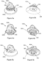
Figure 5a is an upper perspective view of a third traction member shown inFigure 2 ; and -
Figure 5b is a lower perspective view of a third traction member shown inFigure 2 . - According to an embodiment of the present invention, there is provided a
vehicle recovery ladder 100 as shown inFigure 1 . The ladder includes an elongate moldedbody 102, and moldedtraction members 104 that are releasably fastened to thebody 104. Thetraction members 104 are bonded to thebody 102 with a chemical and mechanical bond formed during molding. Advantageously, any damagedtraction members 104 can be readily released and replaced to maintain the performance of theladder 100. - The
traction members 104 are normally less durable than a vehicle tyre so as to sustain damage before the comparatively more expensive tyre. Thetraction members 104 are formed from polymeric material (e.g. elastomer, polyurethane, thermoplastic, nylon). Thebody 102 is also formed from polymeric material (e.g. elastomer, polyurethane, thermoplastic, nylon). Typically, thebody 102 and thetraction members 104 are each intergrally formed (e.g. injection molded) from the same material. -
Figure 2 shows four types oftraction member 104, namely: novel first, second andthird traction members conventional traction member 104d integrally formed with thebody 102. In practice, theladder 100 would usually consist of the same type oftraction member 104. - The
traction members 104b 104c can be clearly seen inFigures 3 to 5 respectively. Eachtraction member 104 includes a rotational release for rotationally releasing thetraction member 104 from thebody 102. The rotational release includes athread 300. The rotational release also includes ahexagonal tool recess 302 for receiving a release tool (e.g. Allan key). - The
ladder 100 includes tongue-in-groove locks for locking thetraction members 104 to thebody 102. In particular, eachtraction member 104 includes an inhibiter 304 for inhibiting unintentional release of thetraction member 104 from thebody 102. The inhibiter 304a of thefirst traction member 104a is a topside tongue for sitting in a complementary groove of thebody 102. The inhibiter 304b of thesecond traction member 104b is an underside groove in which a complementary tongue of thebody 102 sits. The inhibiter 304c of thethird traction member 104c is an underside groove in which a complementary tongue of thebody 102 sits. - Returning to
Figure 2 , thetraction member 104a is released from the rear or underside of theladder 100. Alternatively, thetraction members ladder 100. Eachtraction member 104 includes a broad skirt 200 from which a tooth 202 upwardly extends. Each tooth is flanked by a pair of support fillets 306 (see.Fig 3 ). As can best be seen inFigure 2 , eachtraction member 104 is over-molded by thebody 102 to give increased breadth. - A method of forming the
vehicle recovery ladder 100 is now described. - Firstly, the
traction members 104 are injection molded in a traction member mold and permitted to set before removal. - Next, the
set traction members 104 are positioned in a ladder mold. - Next, the
body 102 is injection molded into the ladder mold and a chemical bond forms between thetraction members 104 andbody 102. A mechanical bond forms with engaging threads of thebody 102 andtraction members 104. As shown inFigure 2 , thebody 102 is overmolded over the embeddedtraction members 104 and forms a complementary thread with thetraction members 104. Thetraction members 104 may have a lower melting point than thebody 102 to facilitate chemical bonding between thetraction members 104 and thebody 102. The chemical bond is formed by crosslinking of the traction member and body materials. - In use, the chemical and mechanical bond is broken when releasing the
traction members 104 from thebody 102. Anothertraction member 104 can be threaded into thebody 102 to replace a releasedtraction member 104. - A person skilled in the art will appreciate that many embodiments and variations can be made without departing from the scope of the present invention as defined by the appended claims.
- The
traction members 104 may be formed from metal material (e.g. metal alloy), ceramic material or rubber material. - In one embodiment, the
traction members 104 may be formed of a different material to thebody 102 to suit the particular application (e.g. hard metal teeth for military operations). Thetraction members 104 may be permanently bonded to, and not releasable from, thebody 102. - The
recess 302 may be pentagonal, octagonal, square, slotted, cross or star shaped. - In compliance with the statute, the invention has been described in language more or less specific to structural or methodical features. It is to be understood that the invention is not limited to specific features shown or described since the means herein described comprises preferred forms of putting the invention into effect.
- Reference throughout this specification to 'one embodiment' or 'an embodiment' means that a particular feature, structure, or characteristic described in connection with the embodiment is included in at least one embodiment of the present invention. Thus, the appearance of the phrases 'in one embodiment' or 'in an embodiment' in various places throughout this specification are not necessarily all referring to the same embodiment.
Claims (9)
- A vehicle recovery ladder (100) including:a body (102);traction members (104) for releasably fastening to the body, the traction members including threads (300);characterized in that the body (102) and the traction members (104) are each integrally formed from the same material, and each traction member (104) is over-molded.
- A vehicle recovery ladder (100) as claimed in claim 1, wherein the traction members (104) are bonded to the body (102) with a chemical and/or mechanical bond.
- A vehicle recovery ladder (100) as claimed in claim 1, wherein the traction members (104) or body (102) include polymeric material; or wherein the traction members (104) include metal material, ceramic material or rubber material.
- A vehicle recovery ladder (100) as claimed in claim 1, wherein- each traction member (104) includes a rotational release means for rotationally releasing the traction member from the body, preferably wherein the rotational release means includes a tool recess for receiving a release tool, or- wherein the ladder includes locks for locking the traction members to the body.
- A vehicle recovery ladder (100) as claimed in claim 1, wherein each traction member (104) includes an inhibiter (304) for inhibiting unintentional release of the traction member (104) from the body (102); preferably wherein the inhibitor (304) includes one or more formations such as a tongue or groove.
- A vehicle recovery ladder (100) as claimed in claim 1, wherein each traction member (104) includes a skirt (200) from which a tooth (202) extends, preferably wherein the thread (300) of each traction member (104) is located either above or below the skirt (200).
- A method for repairing a damaged traction member (104) of a vehicle recovery ladder (100) according to one of claims 1 to 6, the method involving: releasing the traction member (104) from a body (102) of the ladder (100).
- A method as claimed in claim 7, wherein the step of releasing involves rotating the traction member.
- A method of forming a vehicle recovery ladder (100) according to one of claims 1 to 6, the method including the steps of:locating traction members (104) in a mold; andmolding a body (102) to form a bond with the traction members (104).
Applications Claiming Priority (2)
| Application Number | Priority Date | Filing Date | Title |
|---|---|---|---|
| AU2015904551A AU2015904551A0 (en) | 2015-11-06 | Vehicle Recovery Ladder | |
| PCT/AU2016/051051 WO2017075665A1 (en) | 2015-11-06 | 2016-11-04 | Vehicle recovery ladder |
Publications (3)
| Publication Number | Publication Date |
|---|---|
| EP3377333A1 EP3377333A1 (en) | 2018-09-26 |
| EP3377333A4 EP3377333A4 (en) | 2019-07-17 |
| EP3377333B1 true EP3377333B1 (en) | 2020-10-28 |
Family
ID=58661369
Family Applications (1)
| Application Number | Title | Priority Date | Filing Date |
|---|---|---|---|
| EP16861121.8A Active EP3377333B1 (en) | 2015-11-06 | 2016-11-04 | Vehicle recovery ladder |
Country Status (3)
| Country | Link |
|---|---|
| EP (1) | EP3377333B1 (en) |
| AU (5) | AU2016349949B2 (en) |
| WO (1) | WO2017075665A1 (en) |
Families Citing this family (3)
| Publication number | Priority date | Publication date | Assignee | Title |
|---|---|---|---|---|
| AU2019219722B2 (en) * | 2019-03-25 | 2022-12-15 | Sperling Enterprises Pty Ltd | A vehicle recovery board |
| US12049106B2 (en) | 2020-04-29 | 2024-07-30 | Ensen Pty Ltd | Vehicle recovery board |
| US20220073004A1 (en) * | 2020-09-08 | 2022-03-10 | Ford Global Technologies, Llc | Combined vehicle climbing ladder and recovery board |
Family Cites Families (11)
| Publication number | Priority date | Publication date | Assignee | Title |
|---|---|---|---|---|
| US1339612A (en) * | 1919-09-12 | 1920-05-11 | John W Wilkins | Automobile-tool |
| US3152761A (en) * | 1962-01-15 | 1964-10-13 | E L Post & Co Inc | Dual grip device |
| US3836075A (en) * | 1972-09-05 | 1974-09-17 | J Botbol | Cleated emergency track |
| US3861592A (en) * | 1973-06-29 | 1975-01-21 | Sandor Jehuda Fisher | Traction mat |
| US4210280A (en) * | 1978-04-27 | 1980-07-01 | Reisner Robert J | Traction mat |
| JPS62261503A (en) * | 1986-05-08 | 1987-11-13 | Toray Ind Inc | High frictional sheet for getting out of vehicle |
| US5538183A (en) * | 1995-05-30 | 1996-07-23 | Mcgee; John D. | Vehicle traction mat |
| CA2179878A1 (en) * | 1996-06-25 | 1997-12-26 | Philip R. Japp | Studded traction assist strip |
| US8231066B2 (en) * | 2005-10-14 | 2012-07-31 | Paula Rachel Lange and Julie-Anne McCarthy | Vehicle recovery and traction ladder |
| AU2013206349A1 (en) * | 2012-07-11 | 2014-01-30 | Maxtrax Australia Pty Ltd | A Vehicle Recovery Device |
| CA3003626C (en) * | 2015-10-30 | 2023-12-05 | Ip Reserve Pty Ltd | A vehicular ladder |
-
2016
- 2016-11-04 AU AU2016349949A patent/AU2016349949B2/en active Active
- 2016-11-04 EP EP16861121.8A patent/EP3377333B1/en active Active
- 2016-11-04 WO PCT/AU2016/051051 patent/WO2017075665A1/en not_active Ceased
-
2018
- 2018-01-23 AU AU2018200543A patent/AU2018200543B2/en active Active
-
2019
- 2019-08-29 AU AU2019100973A patent/AU2019100973A4/en not_active Expired
- 2019-10-01 AU AU2019240591A patent/AU2019240591B2/en active Active
-
2021
- 2021-06-18 AU AU2021103460A patent/AU2021103460A4/en not_active Expired
Non-Patent Citations (1)
| Title |
|---|
| None * |
Also Published As
| Publication number | Publication date |
|---|---|
| AU2019240591A1 (en) | 2019-10-17 |
| EP3377333A1 (en) | 2018-09-26 |
| WO2017075665A1 (en) | 2017-05-11 |
| AU2018200543A1 (en) | 2018-02-15 |
| AU2018200543B2 (en) | 2019-12-05 |
| EP3377333A4 (en) | 2019-07-17 |
| AU2019240591B2 (en) | 2021-07-01 |
| AU2021103460A4 (en) | 2021-08-12 |
| AU2019100973A4 (en) | 2019-10-03 |
| AU2016349949B2 (en) | 2017-11-02 |
| AU2016349949A1 (en) | 2017-10-12 |
Similar Documents
| Publication | Publication Date | Title |
|---|---|---|
| US10661606B2 (en) | Vehicle recovery ladder | |
| AU2021103460A4 (en) | Method of forming a vehicle recovery ladder | |
| AU2020104265A4 (en) | A vehicular ladder | |
| KR200471421Y1 (en) | Tire cover for snow | |
| AU2021103310A4 (en) | A coupling arrangement | |
| KR102012764B1 (en) | Support structure for wheel | |
| CN100358737C (en) | Crown ply reinforcement for a tire | |
| US582511A (en) | Pneumatic tire | |
| US1932267A (en) | Tractor lug guard | |
| US20040174069A1 (en) | Laterally reinforced endless belt track | |
| KR101084043B1 (en) | Heavy Duty Tires with Recyclable Grooves | |
| JP3647360B2 (en) | Synthetic resin block for road and its mounting method | |
| US1230967A (en) | Manufacture of block-tires. | |
| JP2006002430A (en) | Attention arousing tool | |
| US915918A (en) | Patch for vehicle-tires. | |
| US644288A (en) | Tire for wheels. | |
| JPH0442170B2 (en) | ||
| US1340629A (en) | Antislipping tire-armor | |
| US383130A (en) | Vehicle-wheel | |
| US1102084A (en) | Tire-protector. | |
| USRE11168E (en) | Wheel | |
| DE8534931U1 (en) | Anti-theft device for vehicles | |
| US294890A (en) | Car-wheel | |
| KR20130013901A (en) | Circular grooving construction method | |
| JP2007138640A (en) | Method of surfacing concrete for cast-in-place pile and covering material |
Legal Events
| Date | Code | Title | Description |
|---|---|---|---|
| STAA | Information on the status of an ep patent application or granted ep patent |
Free format text: STATUS: THE INTERNATIONAL PUBLICATION HAS BEEN MADE |
|
| PUAI | Public reference made under article 153(3) epc to a published international application that has entered the european phase |
Free format text: ORIGINAL CODE: 0009012 |
|
| STAA | Information on the status of an ep patent application or granted ep patent |
Free format text: STATUS: REQUEST FOR EXAMINATION WAS MADE |
|
| 17P | Request for examination filed |
Effective date: 20180606 |
|
| AK | Designated contracting states |
Kind code of ref document: A1 Designated state(s): AL AT BE BG CH CY CZ DE DK EE ES FI FR GB GR HR HU IE IS IT LI LT LU LV MC MK MT NL NO PL PT RO RS SE SI SK SM TR |
|
| AX | Request for extension of the european patent |
Extension state: BA ME |
|
| DAV | Request for validation of the european patent (deleted) | ||
| DAX | Request for extension of the european patent (deleted) | ||
| A4 | Supplementary search report drawn up and despatched |
Effective date: 20190618 |
|
| RIC1 | Information provided on ipc code assigned before grant |
Ipc: B60B 39/12 20060101AFI20190612BHEP |
|
| GRAP | Despatch of communication of intention to grant a patent |
Free format text: ORIGINAL CODE: EPIDOSNIGR1 |
|
| STAA | Information on the status of an ep patent application or granted ep patent |
Free format text: STATUS: GRANT OF PATENT IS INTENDED |
|
| INTG | Intention to grant announced |
Effective date: 20200526 |
|
| GRAS | Grant fee paid |
Free format text: ORIGINAL CODE: EPIDOSNIGR3 |
|
| GRAA | (expected) grant |
Free format text: ORIGINAL CODE: 0009210 |
|
| STAA | Information on the status of an ep patent application or granted ep patent |
Free format text: STATUS: THE PATENT HAS BEEN GRANTED |
|
| AK | Designated contracting states |
Kind code of ref document: B1 Designated state(s): AL AT BE BG CH CY CZ DE DK EE ES FI FR GB GR HR HU IE IS IT LI LT LU LV MC MK MT NL NO PL PT RO RS SE SI SK SM TR |
|
| REG | Reference to a national code |
Ref country code: GB Ref legal event code: FG4D |
|
| REG | Reference to a national code |
Ref country code: CH Ref legal event code: EP |
|
| REG | Reference to a national code |
Ref country code: DE Ref legal event code: R096 Ref document number: 602016046887 Country of ref document: DE |
|
| REG | Reference to a national code |
Ref country code: AT Ref legal event code: REF Ref document number: 1327847 Country of ref document: AT Kind code of ref document: T Effective date: 20201115 |
|
| REG | Reference to a national code |
Ref country code: IE Ref legal event code: FG4D |
|
| REG | Reference to a national code |
Ref country code: AT Ref legal event code: MK05 Ref document number: 1327847 Country of ref document: AT Kind code of ref document: T Effective date: 20201028 |
|
| REG | Reference to a national code |
Ref country code: NL Ref legal event code: MP Effective date: 20201028 |
|
| PG25 | Lapsed in a contracting state [announced via postgrant information from national office to epo] |
Ref country code: FI Free format text: LAPSE BECAUSE OF FAILURE TO SUBMIT A TRANSLATION OF THE DESCRIPTION OR TO PAY THE FEE WITHIN THE PRESCRIBED TIME-LIMIT Effective date: 20201028 Ref country code: GR Free format text: LAPSE BECAUSE OF FAILURE TO SUBMIT A TRANSLATION OF THE DESCRIPTION OR TO PAY THE FEE WITHIN THE PRESCRIBED TIME-LIMIT Effective date: 20210129 Ref country code: RS Free format text: LAPSE BECAUSE OF FAILURE TO SUBMIT A TRANSLATION OF THE DESCRIPTION OR TO PAY THE FEE WITHIN THE PRESCRIBED TIME-LIMIT Effective date: 20201028 Ref country code: PT Free format text: LAPSE BECAUSE OF FAILURE TO SUBMIT A TRANSLATION OF THE DESCRIPTION OR TO PAY THE FEE WITHIN THE PRESCRIBED TIME-LIMIT Effective date: 20210301 Ref country code: NO Free format text: LAPSE BECAUSE OF FAILURE TO SUBMIT A TRANSLATION OF THE DESCRIPTION OR TO PAY THE FEE WITHIN THE PRESCRIBED TIME-LIMIT Effective date: 20210128 |
|
| REG | Reference to a national code |
Ref country code: LT Ref legal event code: MG4D |
|
| PG25 | Lapsed in a contracting state [announced via postgrant information from national office to epo] |
Ref country code: AT Free format text: LAPSE BECAUSE OF FAILURE TO SUBMIT A TRANSLATION OF THE DESCRIPTION OR TO PAY THE FEE WITHIN THE PRESCRIBED TIME-LIMIT Effective date: 20201028 Ref country code: ES Free format text: LAPSE BECAUSE OF FAILURE TO SUBMIT A TRANSLATION OF THE DESCRIPTION OR TO PAY THE FEE WITHIN THE PRESCRIBED TIME-LIMIT Effective date: 20201028 Ref country code: BG Free format text: LAPSE BECAUSE OF FAILURE TO SUBMIT A TRANSLATION OF THE DESCRIPTION OR TO PAY THE FEE WITHIN THE PRESCRIBED TIME-LIMIT Effective date: 20210128 Ref country code: PL Free format text: LAPSE BECAUSE OF FAILURE TO SUBMIT A TRANSLATION OF THE DESCRIPTION OR TO PAY THE FEE WITHIN THE PRESCRIBED TIME-LIMIT Effective date: 20201028 Ref country code: IS Free format text: LAPSE BECAUSE OF FAILURE TO SUBMIT A TRANSLATION OF THE DESCRIPTION OR TO PAY THE FEE WITHIN THE PRESCRIBED TIME-LIMIT Effective date: 20210228 Ref country code: LV Free format text: LAPSE BECAUSE OF FAILURE TO SUBMIT A TRANSLATION OF THE DESCRIPTION OR TO PAY THE FEE WITHIN THE PRESCRIBED TIME-LIMIT Effective date: 20201028 Ref country code: SE Free format text: LAPSE BECAUSE OF FAILURE TO SUBMIT A TRANSLATION OF THE DESCRIPTION OR TO PAY THE FEE WITHIN THE PRESCRIBED TIME-LIMIT Effective date: 20201028 |
|
| PG25 | Lapsed in a contracting state [announced via postgrant information from national office to epo] |
Ref country code: NL Free format text: LAPSE BECAUSE OF FAILURE TO SUBMIT A TRANSLATION OF THE DESCRIPTION OR TO PAY THE FEE WITHIN THE PRESCRIBED TIME-LIMIT Effective date: 20201028 Ref country code: HR Free format text: LAPSE BECAUSE OF FAILURE TO SUBMIT A TRANSLATION OF THE DESCRIPTION OR TO PAY THE FEE WITHIN THE PRESCRIBED TIME-LIMIT Effective date: 20201028 |
|
| REG | Reference to a national code |
Ref country code: CH Ref legal event code: PL |
|
| REG | Reference to a national code |
Ref country code: DE Ref legal event code: R097 Ref document number: 602016046887 Country of ref document: DE |
|
| PG25 | Lapsed in a contracting state [announced via postgrant information from national office to epo] |
Ref country code: MC Free format text: LAPSE BECAUSE OF FAILURE TO SUBMIT A TRANSLATION OF THE DESCRIPTION OR TO PAY THE FEE WITHIN THE PRESCRIBED TIME-LIMIT Effective date: 20201028 Ref country code: LU Free format text: LAPSE BECAUSE OF NON-PAYMENT OF DUE FEES Effective date: 20201104 Ref country code: LT Free format text: LAPSE BECAUSE OF FAILURE TO SUBMIT A TRANSLATION OF THE DESCRIPTION OR TO PAY THE FEE WITHIN THE PRESCRIBED TIME-LIMIT Effective date: 20201028 Ref country code: SM Free format text: LAPSE BECAUSE OF FAILURE TO SUBMIT A TRANSLATION OF THE DESCRIPTION OR TO PAY THE FEE WITHIN THE PRESCRIBED TIME-LIMIT Effective date: 20201028 Ref country code: EE Free format text: LAPSE BECAUSE OF FAILURE TO SUBMIT A TRANSLATION OF THE DESCRIPTION OR TO PAY THE FEE WITHIN THE PRESCRIBED TIME-LIMIT Effective date: 20201028 Ref country code: CZ Free format text: LAPSE BECAUSE OF FAILURE TO SUBMIT A TRANSLATION OF THE DESCRIPTION OR TO PAY THE FEE WITHIN THE PRESCRIBED TIME-LIMIT Effective date: 20201028 Ref country code: SK Free format text: LAPSE BECAUSE OF FAILURE TO SUBMIT A TRANSLATION OF THE DESCRIPTION OR TO PAY THE FEE WITHIN THE PRESCRIBED TIME-LIMIT Effective date: 20201028 Ref country code: RO Free format text: LAPSE BECAUSE OF FAILURE TO SUBMIT A TRANSLATION OF THE DESCRIPTION OR TO PAY THE FEE WITHIN THE PRESCRIBED TIME-LIMIT Effective date: 20201028 |
|
| REG | Reference to a national code |
Ref country code: BE Ref legal event code: MM Effective date: 20201130 |
|
| PG25 | Lapsed in a contracting state [announced via postgrant information from national office to epo] |
Ref country code: LI Free format text: LAPSE BECAUSE OF NON-PAYMENT OF DUE FEES Effective date: 20201130 Ref country code: CH Free format text: LAPSE BECAUSE OF NON-PAYMENT OF DUE FEES Effective date: 20201130 Ref country code: DK Free format text: LAPSE BECAUSE OF FAILURE TO SUBMIT A TRANSLATION OF THE DESCRIPTION OR TO PAY THE FEE WITHIN THE PRESCRIBED TIME-LIMIT Effective date: 20201028 |
|
| PLBE | No opposition filed within time limit |
Free format text: ORIGINAL CODE: 0009261 |
|
| STAA | Information on the status of an ep patent application or granted ep patent |
Free format text: STATUS: NO OPPOSITION FILED WITHIN TIME LIMIT |
|
| 26N | No opposition filed |
Effective date: 20210729 |
|
| PG25 | Lapsed in a contracting state [announced via postgrant information from national office to epo] |
Ref country code: IT Free format text: LAPSE BECAUSE OF FAILURE TO SUBMIT A TRANSLATION OF THE DESCRIPTION OR TO PAY THE FEE WITHIN THE PRESCRIBED TIME-LIMIT Effective date: 20201028 Ref country code: AL Free format text: LAPSE BECAUSE OF FAILURE TO SUBMIT A TRANSLATION OF THE DESCRIPTION OR TO PAY THE FEE WITHIN THE PRESCRIBED TIME-LIMIT Effective date: 20201028 Ref country code: IE Free format text: LAPSE BECAUSE OF NON-PAYMENT OF DUE FEES Effective date: 20201104 |
|
| PG25 | Lapsed in a contracting state [announced via postgrant information from national office to epo] |
Ref country code: SI Free format text: LAPSE BECAUSE OF FAILURE TO SUBMIT A TRANSLATION OF THE DESCRIPTION OR TO PAY THE FEE WITHIN THE PRESCRIBED TIME-LIMIT Effective date: 20201028 |
|
| PG25 | Lapsed in a contracting state [announced via postgrant information from national office to epo] |
Ref country code: IS Free format text: LAPSE BECAUSE OF FAILURE TO SUBMIT A TRANSLATION OF THE DESCRIPTION OR TO PAY THE FEE WITHIN THE PRESCRIBED TIME-LIMIT Effective date: 20210228 Ref country code: TR Free format text: LAPSE BECAUSE OF FAILURE TO SUBMIT A TRANSLATION OF THE DESCRIPTION OR TO PAY THE FEE WITHIN THE PRESCRIBED TIME-LIMIT Effective date: 20201028 Ref country code: MT Free format text: LAPSE BECAUSE OF FAILURE TO SUBMIT A TRANSLATION OF THE DESCRIPTION OR TO PAY THE FEE WITHIN THE PRESCRIBED TIME-LIMIT Effective date: 20201028 Ref country code: CY Free format text: LAPSE BECAUSE OF FAILURE TO SUBMIT A TRANSLATION OF THE DESCRIPTION OR TO PAY THE FEE WITHIN THE PRESCRIBED TIME-LIMIT Effective date: 20201028 |
|
| PG25 | Lapsed in a contracting state [announced via postgrant information from national office to epo] |
Ref country code: MK Free format text: LAPSE BECAUSE OF FAILURE TO SUBMIT A TRANSLATION OF THE DESCRIPTION OR TO PAY THE FEE WITHIN THE PRESCRIBED TIME-LIMIT Effective date: 20201028 |
|
| PG25 | Lapsed in a contracting state [announced via postgrant information from national office to epo] |
Ref country code: BE Free format text: LAPSE BECAUSE OF NON-PAYMENT OF DUE FEES Effective date: 20201130 |
|
| P01 | Opt-out of the competence of the unified patent court (upc) registered |
Effective date: 20230530 |
|
| PGFP | Annual fee paid to national office [announced via postgrant information from national office to epo] |
Ref country code: DE Payment date: 20251029 Year of fee payment: 10 |
|
| PGFP | Annual fee paid to national office [announced via postgrant information from national office to epo] |
Ref country code: GB Payment date: 20251014 Year of fee payment: 10 |
|
| PGFP | Annual fee paid to national office [announced via postgrant information from national office to epo] |
Ref country code: FR Payment date: 20251106 Year of fee payment: 10 |