EP3376987B1 - Method of preoperative planning to correct spine misalignment of a patient - Google Patents
Method of preoperative planning to correct spine misalignment of a patient Download PDFInfo
- Publication number
- EP3376987B1 EP3376987B1 EP15828659.1A EP15828659A EP3376987B1 EP 3376987 B1 EP3376987 B1 EP 3376987B1 EP 15828659 A EP15828659 A EP 15828659A EP 3376987 B1 EP3376987 B1 EP 3376987B1
- Authority
- EP
- European Patent Office
- Prior art keywords
- spine
- patient
- vertebrae
- thoracic
- lumbar
- Prior art date
- Legal status (The legal status is an assumption and is not a legal conclusion. Google has not performed a legal analysis and makes no representation as to the accuracy of the status listed.)
- Active
Links
Images









Classifications
-
- A—HUMAN NECESSITIES
- A61—MEDICAL OR VETERINARY SCIENCE; HYGIENE
- A61B—DIAGNOSIS; SURGERY; IDENTIFICATION
- A61B34/00—Computer-aided surgery; Manipulators or robots specially adapted for use in surgery
- A61B34/10—Computer-aided planning, simulation or modelling of surgical operations
-
- A—HUMAN NECESSITIES
- A61—MEDICAL OR VETERINARY SCIENCE; HYGIENE
- A61B—DIAGNOSIS; SURGERY; IDENTIFICATION
- A61B17/00—Surgical instruments, devices or methods
- A61B17/56—Surgical instruments or methods for treatment of bones or joints; Devices specially adapted therefor
- A61B17/58—Surgical instruments or methods for treatment of bones or joints; Devices specially adapted therefor for osteosynthesis, e.g. bone plates, screws or setting implements
- A61B17/68—Internal fixation devices, including fasteners and spinal fixators, even if a part thereof projects from the skin
- A61B17/70—Spinal positioners or stabilisers, e.g. stabilisers comprising fluid filler in an implant
- A61B17/7001—Screws or hooks combined with longitudinal elements which do not contact vertebrae
- A61B17/7002—Longitudinal elements, e.g. rods
- A61B17/7011—Longitudinal element being non-straight, e.g. curved, angled or branched
-
- A—HUMAN NECESSITIES
- A61—MEDICAL OR VETERINARY SCIENCE; HYGIENE
- A61B—DIAGNOSIS; SURGERY; IDENTIFICATION
- A61B17/00—Surgical instruments, devices or methods
- A61B17/56—Surgical instruments or methods for treatment of bones or joints; Devices specially adapted therefor
- A61B17/58—Surgical instruments or methods for treatment of bones or joints; Devices specially adapted therefor for osteosynthesis, e.g. bone plates, screws or setting implements
- A61B17/68—Internal fixation devices, including fasteners and spinal fixators, even if a part thereof projects from the skin
- A61B17/70—Spinal positioners or stabilisers, e.g. stabilisers comprising fluid filler in an implant
- A61B17/7001—Screws or hooks combined with longitudinal elements which do not contact vertebrae
- A61B17/7002—Longitudinal elements, e.g. rods
- A61B17/7011—Longitudinal element being non-straight, e.g. curved, angled or branched
- A61B17/7013—Longitudinal element being non-straight, e.g. curved, angled or branched the shape of the element being adjustable before use
-
- A—HUMAN NECESSITIES
- A61—MEDICAL OR VETERINARY SCIENCE; HYGIENE
- A61B—DIAGNOSIS; SURGERY; IDENTIFICATION
- A61B6/00—Apparatus or devices for radiation diagnosis; Apparatus or devices for radiation diagnosis combined with radiation therapy equipment
- A61B6/50—Apparatus or devices for radiation diagnosis; Apparatus or devices for radiation diagnosis combined with radiation therapy equipment specially adapted for specific body parts; specially adapted for specific clinical applications
- A61B6/505—Apparatus or devices for radiation diagnosis; Apparatus or devices for radiation diagnosis combined with radiation therapy equipment specially adapted for specific body parts; specially adapted for specific clinical applications for diagnosis of bone
-
- A—HUMAN NECESSITIES
- A61—MEDICAL OR VETERINARY SCIENCE; HYGIENE
- A61B—DIAGNOSIS; SURGERY; IDENTIFICATION
- A61B6/00—Apparatus or devices for radiation diagnosis; Apparatus or devices for radiation diagnosis combined with radiation therapy equipment
- A61B6/52—Devices using data or image processing specially adapted for radiation diagnosis
- A61B6/5211—Devices using data or image processing specially adapted for radiation diagnosis involving processing of medical diagnostic data
- A61B6/5217—Devices using data or image processing specially adapted for radiation diagnosis involving processing of medical diagnostic data extracting a diagnostic or physiological parameter from medical diagnostic data
-
- A—HUMAN NECESSITIES
- A61—MEDICAL OR VETERINARY SCIENCE; HYGIENE
- A61B—DIAGNOSIS; SURGERY; IDENTIFICATION
- A61B34/00—Computer-aided surgery; Manipulators or robots specially adapted for use in surgery
- A61B34/10—Computer-aided planning, simulation or modelling of surgical operations
- A61B2034/101—Computer-aided simulation of surgical operations
- A61B2034/102—Modelling of surgical devices, implants or prosthesis
-
- A—HUMAN NECESSITIES
- A61—MEDICAL OR VETERINARY SCIENCE; HYGIENE
- A61B—DIAGNOSIS; SURGERY; IDENTIFICATION
- A61B34/00—Computer-aided surgery; Manipulators or robots specially adapted for use in surgery
- A61B34/10—Computer-aided planning, simulation or modelling of surgical operations
- A61B2034/101—Computer-aided simulation of surgical operations
- A61B2034/105—Modelling of the patient, e.g. for ligaments or bones
-
- A—HUMAN NECESSITIES
- A61—MEDICAL OR VETERINARY SCIENCE; HYGIENE
- A61B—DIAGNOSIS; SURGERY; IDENTIFICATION
- A61B90/00—Instruments, implements or accessories specially adapted for surgery or diagnosis and not covered by any of the groups A61B1/00 - A61B50/00, e.g. for luxation treatment or for protecting wound edges
- A61B90/36—Image-producing devices or illumination devices not otherwise provided for
- A61B2090/364—Correlation of different images or relation of image positions in respect to the body
- A61B2090/367—Correlation of different images or relation of image positions in respect to the body creating a 3D dataset from 2D images using position information
Definitions
- the invention relates to a method of preoperative planning to correct spine misalignment of a patient and to the associated pre-shaped or pre-twisted rod, to be integrated within a patient body to support a patient spine, which has been pre-shaped or pre-twisted according to position and orientation of a set of imaged vertebrae after a step of making a translation and a rotation in a sagittal plane performed during such a method of preoperative planning to correct spine misalignment of a patient.
- a method of preoperative planning to correct spine misalignment of a patient based on a step of making a translation and a rotation, in a sagittal plane, of each vertebra of a set of several cervical and/or thoracic and/or lumbar imaged spine vertebrae, so that said set of imaged vertebrae presents afterwards, in the sagittal plane, the same cervical lordosis and/or the same thoracic kyphosis and/or the same lumbar lordosis as a model adapted for said patient.
- the length of the rod is not the correct one, and if cervical lordosis and/or thoracic kyphosis and/or lumbar lordosis present correct curvatures, these curvatures are not located at the right place, specific points of these curvatures, like for example maximum points, minimum points, inflexion points, are shifted and located at the wrong parts of the vertebrae if not at the wrong vertebrae.
- US2015100091 discloses a method provided for correcting a curvature or deformity in a patient's spine based on the digitized locations of implanted screws and tracking the placement of the rod as it is placed in a minimally invasive fashion.
- the method is implemented by a control unit through a GUI to digitize screw locations, accept one or more correction outputs, and generate one or more rod solution outputs shaped to fit at locations distinct from the implanted screw locations.
- the object of the present invention is to alleviate at least partly the above mentioned drawbacks.
- the invention aims to provide for a more precise method of preoperative planning to correct spine misalignment of a patient leading to an associated pre-twisted rod presenting a more precise length and/or a more precise location of at least one of the curvatures of cervical lordosis and/or thoracic kyphosis and/or lumbar lordosis, preferably presenting a more precise length and a more precise location of at least of the curvatures of all imaged and studied spine portions among cervical lordosis and/or thoracic kyphosis and/or lumbar lordosis.
- the invention proposes, before the step of making translation and rotation in a sagittal plane of the imaged spine vertebrae, to make a translation and a rotation, in a coronal plane, of the imaged spine vertebrae so as to make them straight in the coronal plane, and a rotation, in an axial plane, of the imaged spine vertebrae so as to make them axially aligned.
- the step of making translation and rotation in a sagittal plane of the imaged spine vertebrae can be performed on an imaged spine already corrected from scoliosis and from axial vertebrae misalignment.
- the correct cervical lordosis and/or thoracic kyphosis and/or lumbar lordosis may then be implemented on an imaged spine presenting already a straight axis in the coronal plane and an axially aligned imaged spine in the axial plane.
- the obtained pre-twisted rod is then much more precise, in length and/or in curvature location, having been manufactured or deformed according to a completely correctly amended imaged spine and not according to a partly correctly amended imaged spine as in prior art.
- a method of preoperative planning to correct spine misalignment of a patient comprising a step of making a translation and a rotation, in a sagittal plane, of each vertebra of a set of several cervical and/or thoracic and/or lumbar imaged spine vertebrae, so that said set of imaged vertebrae presents afterwards, in the sagittal plane, the same cervical lordosis and/or the same thoracic kyphosis and/or the same lumbar lordosis as a model adapted for said patient, wherein it also comprises, before said step of making said translation and said rotation in a sagittal plane: a step of making a translation and a rotation, in a coronal plane, of each vertebra of said set of several cervical and/or thoracic and/or lumbar imaged spine vertebrae, so that said set of imaged vertebrae becomes straight in said coronal plane, and of making a rotation, in an axial plane, of each
- Making a translation and a rotation, in a coronal plane, of each vertebra, and making a rotation, in an axial plane, of each vertebra may be performed either successively in two successive steps or simultaneously within the same step.
- the step of making a translation and a rotation, in a coronal plane, of each vertebra may be performed before the step of making a rotation, in an axial plane, of each vertebra.
- the step of making a translation and a rotation, in an axial plane, of each vertebra may be performed before the step of making a rotation, in a coronal plane, of each vertebra.
- the translation in the coronal plan is performed with the first rotation, either the one in coronal plan or the one in axial plan. It is also possible, although less efficient, to perform each step separately, in whatever order, one step being a translation in coronal plan, one other step being a rotation in axial plan, still one other step being a rotation in axial plan.
- This method of preoperative planning to correct spine misalignment of a patient means that the steps of making translations and rotations, in different planes, of imaged vertebrae, are indeed steps of making translations and rotations of elements or parts of images, on a display device as for example on a screen. Only portions of images or elements within images are translated and/or rotated on a display device during this preoperative planning; no real vertebrae of a patient spine are examined, touched or moved during this preoperative planning.
- a method of preoperative planning to correct spine misalignment of a patient comprising a step of making a translation and a rotation, in a sagittal plane, of each vertebra of a set of several thoracic and/or lumbar imaged spine vertebrae, so that said set of imaged vertebrae presents afterwards, in the sagittal plane, the same thoracic kyphosis and/or the same lumbar lordosis as a model adapted for said patient, wherein it also comprises, before said step of making said translation and said rotation in a sagittal plane, successively: a step of making a translation and a rotation, in a coronal plane, of each vertebra of said set of several thoracic and/or lumbar imaged spine vertebrae, so that said set of imaged vertebrae becomes straight in said coronal plane, a step of making a rotation, in an axial plane, of each vertebra of said set of several thoracic and/or
- Preferred embodiments comprise one or more of the following features, which can be taken separately or together, either in partial combination or in full combination.
- the method of preoperative planning to correct spine misalignment of a patient according to the invention is applied to a set of several thoracic and several lumbar imaged spine vertebrae, so that said set of imaged vertebrae presents, in the sagittal plane, the same thoracic kyphosis and the same lumbar lordosis as a model adapted for said patient.
- the preoperative planning to correct spine misalignment of a patient and the associated pre-twisted rod will encompass a key part of patient spine, including both thoracic and lumbar vertebrae.
- the method of preoperative planning to correct spine misalignment of a patient according to the invention is applied to all thoracic and all lumbar spine vertebrae, so that said patient spine presents, in the sagittal plane, the same thoracic kyphosis and the same lumbar lordosis as a model adapted for said patient.
- the preoperative planning to correct spine misalignment of a patient and the associated pre-twisted rod will encompass most of patient spine, including all thoracic and all lumbar vertebrae.
- said translation and rotation are performed simultaneously
- said translation and rotation are performed simultaneously.
- This is more efficient and more realistic to perform both translation and rotation of an imaged vertebra at the same time, since afterwards during operative treatment; the surgeon will perform those vertebra moves at the same time on the real vertebrae of the patient spine to effectively correct this patient spine misalignment.
- the method of preoperative planning to correct spine misalignment of a patient also comprises, after said steps of making translations and rotations: a step of pre-twisting at least one rod, to be integrated within said patient body to support said patient spine, according to position and orientation of said set of imaged vertebrae after said step of making said translation and said rotation in a sagittal plane.
- a step of pre-twisting at least one rod to be integrated within said patient body to support said patient spine, according to position and orientation of said set of imaged vertebrae after said step of making said translation and said rotation in a sagittal plane.
- two rods are pre-twisted which are to be integrated respectively on both sides of said patient spine.
- the method of preoperative planning to correct spine misalignment of a patient also comprises, after said steps of making translations and rotations: a step of editing a pattern of at least one pre-twisted rod to be integrated within said patient body to support said patient spine, according to position and orientation of said set of imaged vertebrae after said step of making said translation and said rotation in a sagittal plane.
- a step of editing a pattern of at least one pre-twisted rod to be integrated within said patient body to support said patient spine according to position and orientation of said set of imaged vertebrae after said step of making said translation and said rotation in a sagittal plane.
- the method of preoperative planning to correct spine misalignment of patient also comprises, after said steps of making translations and rotations: a step of calculating the length of at least one rod, to be integrated within said patient body to support said patient spine, according to position and orientation of said set of imaged vertebrae after said step of making said translation and said rotation in a sagittal plane.
- a step of calculating the length of at least one rod to be integrated within said patient body to support said patient spine, according to position and orientation of said set of imaged vertebrae after said step of making said translation and said rotation in a sagittal plane.
- said set of several thoracic and/or lumbar imaged spine vertebrae is a 3D spine image reconstructed from two 2D radiographic spine images, preferably from a coronal image and a sagittal image.
- a performing 3D preoperative planning can be made on patient spine, leading to a performing pre-twisted rod correctly deformed in the three dimensional space.
- lumbar lordosis position is obtained by moving two end markers corresponding respectively to higher extreme lumbar vertebra and sacral plate and lumbar lordosis curvature is obtained by moving an intermediate marker corresponding to an intermediate lumbar vertebra located between both extreme lumbar vertebrae, and/or thoracic kyphosis position is obtained by moving two end markers corresponding respectively to both extreme thoracic vertebrae, and thoracic kyphosis curvature is obtained by moving an intermediate marker corresponding to an intermediate thoracic vertebra located between both extreme thoracic vertebrae, and/or cervical lordosis position is obtained by moving two end markers corresponding respectively to both extreme cervical vertebrae and cervical lordosis curvature is obtained by moving an intermediate marker corresponding to an intermediate cervical vertebra located between both extreme cervical vertebrae.
- said model is adapted for said patient first by getting an adapted lordosis from one or more patient based parameters and second by getting an adapted kyphosis from said adapted lordosis and from one or more patient based parameters.
- the obtained model will be more efficient when lumbar lordosis is adapted first, and when then only, with an optimized and more or less fixed lumbar lordosis (or at most varying within a narrowly limited range), the thoracic kyphosis is adapted.
- said adapted lordosis is obtained from patient pelvic incidence and from patient population type and preferably also from patient age. This leads to an optimized compromise between the precision of the curvature(s) implemented and the complexity of calculation to get the right curvature(s).
- said adapted kyphosis is obtained from said adapted lordosis and from patient sagittal vertical axis. This leads to an optimized compromise between the precision of the curvature(s) implemented and the complexity of calculation to get the right curvature(s).
- said adapted kyphosis is obtained by varying said adapted lordosis curvature within a limited range, preferably plus or minus 10 degrees, while minimizing said patient sagittal vertical axis.
- a limited range preferably plus or minus 10 degrees
- This flexibility allowing to still amend the lumbar lordosis during step of thoracic kyphosis determination after step of lumbar lordosis determination has been completed, such amendment being performed within a narrowly limited range, allows for quicker and more efficient convergence of the thoracic kyphosis than the convergence which would be obtained with a completely fixed value of lumbar lordosis.
- said spinal misalignment comes from a scoliosis and/or from a degenerative spine.
- Those are the diseases which can be corrected thanks to the method of preoperative planning to correct spine misalignment of a patient and/or to the associated pre-twisted rod(s), both according to embodiments of the invention.
- a pre-twisted rod to be integrated within a patient body to support a patient spine, which has been pre-twisted according to position and orientation of a set of imaged vertebrae after a step of making a translation and a rotation in a sagittal plane performed during a method of preoperative planning to correct spine misalignment of a patient according to the disclosure.
- This pre-twisted rod may be used afterwards directly by the surgeon during subsequent operative treatment.
- Fig. 1 shows a frontal patient spine view, the patient suffering from scoliosis, allowing performance of a step of the method of preoperative planning according to an embodiment of the invention.
- a patient spine 1 comprises vertebrae 2 and is ended by pelvis 3.
- Vertebrae 2 comprise thoracic vertebrae T1 to T12 and lumbar vertebrae L1 to L5.
- a sane spine 1 should appear as vertical in the coronal plan.
- the spine 1 is heavily curved toward left of figure 1 in its upper part, corresponding to thoracic vertebrae 2, and slightly curved toward right of figure 1 in its lower part, corresponding to lumbar vertebrae 2.
- This means that represented spine 1 suffers from a disease called scoliosis.
- This means that represented spine 1 should be made straight in coronal plan. Therefore, imaged thoracic vertebrae T1 to T12 should be moved to the right of figure 1 , whereas imaged lumbar vertebrae L1 to L5 should be moved to the left of figure 1 .
- Fig. 2 shows a frontal patient spine view, the spine having been partly derotated during preoperative planning, allowing performance of a step of the method of preoperative planning according to an embodiment of the invention.
- the thoracic vertebrae 2 comprise thoracic vertebrae T1, T2, T3, T4, T5, T6, T7, T8, T9, T10, T11, T12.
- the lumbar vertebrae 2 comprise lumbar vertebrae L1, L2, L3, L4, L5.
- the spine 1 is straight, what means all vertebrae 2 are vertically aligned.
- the represented spine 1 is a sane spine with respect to coronal plan. So, the spine 1, represented on figure 1 , suffering from scoliosis, should be healed so as to become the straight spine 1 in coronal plan of figure 2 , appearing to be sane with respect to coronal plan. Therefore, all imaged vertebrae 2 of figure 1 will have to be derotated, i.e. to undergo a derotation, so as to become straight in coronal plan as on figure 2 . This derotation will include indeed a rotation and a translation to be performed simultaneously.
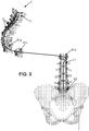
- Fig. 3 shows a frontal patient spine view, where a starting phase of translation and rotation, in a coronal plane, allowing performance of a step of the method of preoperative planning according to an embodiment of the invention. During derotation, intervertebral space is maintained.
- each vertebra 2 will be simultaneously translated and rotated in the coronal plan of figure 3 , so that the spine 1 becomes straight in coronal plan of figure 3 .
- lumbar vertebrae L5 to L1 and thoracic vertebra T12 have already undergone such combined translation and rotation in coronal plan and are already vertically aligned in coronal plan.
- Thoracic vertebra T11 has just started its combined translation and rotation in coronal plan.
- Thoracic vertebrae T10 to T1 are still in their original position corresponding to scoliosis of spine 1, waiting for derotation.
- Fig. 4 shows a frontal patient spine view, where an ending phase of translation and rotation, in a coronal plane, allowing performance of a step of the method of preoperative planning according to an embodiment of the invention.
- lumbar vertebrae L5 to L1 and thoracic vertebra T12 have already undergone such combined translation and rotation in coronal plan and are already vertically aligned in coronal plan.
- Thoracic vertebra T11 is about ending its combined translation and rotation in coronal plan.
- Thoracic vertebrae T10 to T1 are still in their original position corresponding to scoliosis of spine 1, waiting for derotation.
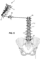
- Fig. 5 shows a frontal patient spine view, where a starting phase of translation and rotation, in an axial plane, allowing performance of a step of the method of preoperative planning according to an embodiment of the invention.
- each vertebra 2 will be simultaneously translated and rotated in the axial plan of figure 5 , so that the spine 1 becomes straight in axial plan of figure 5 .
- lumbar vertebrae L5 to L1 and thoracic vertebra T12 to T9 have already undergone such combined translation and rotation in axial plan and are already vertically aligned in axial plan.
- Thoracic vertebra T8 has just started its combined translation and rotation in axial plan.
- Thoracic vertebrae T7 to T1 are still in their original position corresponding to scoliosis of spine 1, waiting for derotation.
- Fig. 6 shows a frontal patient spine view, where an ending phase of translation and rotation, in an axial plane, allowing performance of a step of the method of preoperative planning according to an embodiment of the invention.
- lumbar vertebrae L5 to L1 and thoracic vertebra T12 to T9 have already undergone such combined translation and rotation in axial plan and are already vertically aligned in axial plan.
- Thoracic vertebra T8 is ending its combined translation and rotation in axial plan.
- Thoracic vertebrae T7 to T1 are still in their original position corresponding to scoliosis of spine 1, waiting for derotation.
- Figures 3-6 have shown both derotations in coronal plan and in axial plan.
- both derotations may be performed the following way: combined translation in coronal plan and rotations respectively in coronal and axial plans are performed either successively or simultaneously with the imaged vertebrae 2 on display device during preoperative planning so that, at the end, spine 1 becomes aligned in coronal and axial plans, in a similar way as will be made with the real vertebrae later during operative treatment.
- Fig. 7 shows a lateral patient spine view, with a high value of thoracic kyphosis, allowing performance of a step of the method of preoperative planning according to an embodiment of the invention.
- Spine curvature should be changed so as to provide for a closer to zero (or better a close to zero) value of sagittal vertical axis.
- Spine 1 is articulated on sacral plate S1 of pelvis 3 and comprises vertebrae 2 among which thoracic vertebrae T1 to T12 and lumbar vertebrae L1 to L5.
- the lumbar lordosis is the curvature of curve C2 of spine 1 on a subset of lumbar vertebrae L1 to L5. It can be determined as the angle between two directions D1 and D2 which correspond respectively to sacral plate S1 of pelvis orientation and to upper plate of lumbar vertebra L1 orientation. Its value on figure 7 is 71.4 degrees.
- an intermediate marker 8 can be moved on the display device by the operator so as to change the curvature of curve C2 between two end markers 7 and 9 which remain fixedly respectively located on first lumbar vertebra L1 and on sacral plate S1 of pelvis 3.
- the curve C2 is also displaced, since intermediate marker 8 stays on this curve C2.
- the intermediate marker 8 can be moved up and down along spine 1 axis in order to change curvature distribution as well as perpendicularly to spine 1 axis in order to change curvature direction and curvature amplitude.
- the bounds of this intermediate marker 8 displacement are along spine 1 axis the extreme lumbar vertebrae L1 and L5, and perpendicularly to spine 1 axis the maximum amplitude corresponding to maximal curvature that the lumbar vertebrae L1 to L5 may bear without damage.
- the thoracic kyphosis is the curvature of curve C1 of spine 1 on a subset of thoracic vertebrae T1 to T12. It can be determined as the angle between two directions D3 and D4 which correspond respectively to lower plate of thoracic vertebra T12 orientation and to upper plate of thoracic vertebra T1 orientation. Its value on figure 7 is 50.7 degrees.
- an intermediate marker 5 can be moved on the display device by the operator so as to change the curvature of curve C1 between two end markers 4 and 6 which remain fixedly respectively located on first thoracic vertebra T1 and on last thoracic vertebra T12 or preferably more precisely just in between last thoracic vertebra T12 and first lumbar vertebra L1.
- the curve C1 is also displaced, since intermediate marker 5 stays on this curve C1.
- the intermediate marker 5 can be moved up and down along spine 1 axis in order to change curvature distribution as well as perpendicularly to spine 1 axis in order to change curvature direction and curvature amplitude.
- the bounds of this intermediate marker 5 displacement are along spine 1 axis the extreme thoracic vertebrae T1 and T12, and perpendicularly to spine 1 axis the maximum amplitude corresponding to maximal curvature that the thoracic vertebrae T1 to T12 may bear without damage.
- the sagittal vertical axis value E1 is -115.4mm. This value should be brought close to zero, if possible and while respecting the scheduled values of lumbar lordosis and thoracic kyphosis for this specific patient, so that spine 1 becomes more balanced and may correspond to saner thoracic kyphosis and lumbar lordosis. On figure 7 , the value of thoracic kyphosis, which is too high, should therefore be reduced.
- Fig. 8 shows a lateral patient spine view, with a high value of lumbar lordosis, allowing performance of a step of the method of preoperative planning according to an embodiment of the invention.
- Spine curvature should be changed so as to provide for a closer to zero (or better a close to zero) value of sagittal vertical axis.
- the value of lumbar lordosis is on figure 8 is 91.1 degrees.
- an intermediate marker 8 can be moved on the display device by the operator so as to change the curvature of curve C2 between two end markers 7 and 9 which remain fixedly respectively located on first lumbar vertebra L1 and on sacral plate S1 of pelvis 3.
- the curve C2 is also displaced, since intermediate marker 8 stays on this curve C2.
- the value of thoracic kyphosis is on figure 8 is 41.0 degrees.
- an intermediate marker 5 can be moved on the display device by the operator so as to change the curvature of curve C1 between two end markers 4 and 6 which remain fixedly respectively located on first thoracic vertebra T1 and on last thoracic vertebra T12 or preferably more precisely just in between last thoracic vertebra T12 and first lumbar vertebra L1.
- the curve C1 is also displaced, since intermediate marker 5 stays on this curve C1.
- the sagittal vertical axis value E1 is 4.2mm. This value should be brought close to zero, if possible and while respecting the scheduled values of lumbar lordosis and thoracic kyphosis for this specific patient, so that spine 1 becomes more balanced and may correspond to saner thoracic kyphosis and lumbar lordosis. On figure 8 , the value of lumbar lordosis, which is too high, should therefore be reduced.
- Fig. 9 shows a lateral patient spine view, with a close to zero value of sagittal vertical axis, allowing performance of a step of the method of preoperative planning according to an embodiment of the invention.
- Spine curvature is adapted because the value of sagittal vertical axis is already close to zero.
- the value of lumbar lordosis is on figure 9 is 86.0 degrees.
- an intermediate marker 8 can be moved on the display device by the operator so as to change the curvature of curve C2 between two end markers 7 and 9.
- thoracic kyphosis is on figure 9 is 34.5 degrees.
- an intermediate marker 5 can be moved on the display device by the operator so as to change the curvature of curve C1 between two end markers 4 and 6.
- the sagittal vertical axis value E1 is -1.5mm. This value is indeed very close to zero.
- corresponding spine 1 is well balanced and corresponds to sane thoracic kyphosis and lumbar lordosis.
- Fig. 10 shows a lateral patient spine view, with a lumbar lordosis concentrated in the middle region of lumbar vertebrae, allowing performance of a step of the method of preoperative planning according to an embodiment of the invention.
- Spine curvature should be changed so as to provide for a closer to zero (or better a close to zero) value of sagittal vertical axis.
- the value of lumbar lordosis is on figure 10 is 76.4 degrees.
- the lumbar lordosis is concentrated in the middle region of lumbar vertebrae 2; therefore intermediate marker 8 is halfway between end markers 7 and 9.
- intermediate marker 8 can be moved on the display device by the operator so as to change the curvature of curve C2 between two end markers 7 and 9.
- thoracic kyphosis is on figure 10 is 34.5 degrees.
- the thoracic kyphosis is concentrated in the middle region of thoracic vertebrae 2; therefore intermediate marker 5 is halfway between end markers 4 and 6.
- intermediate marker 5 can be moved on the display device by the operator so as to change the curvature of curve C1 between two end markers 4 and 6.
- the sagittal vertical axis value E1 is -53.1mm. This value should be brought close to zero, if possible and while respecting the scheduled values of lumbar lordosis and thoracic kyphosis for this specific patient, so that spine 1 becomes more balanced.
- Fig. 11 shows a lateral patient spine view, with a lumbar lordosis concentrated in the lower region of lumbar vertebrae, allowing performance of a step of the method of preoperative planning according to an embodiment of the invention.
- Spine curvature should be changed so as to provide for a closer to zero (or better a close to zero) value of sagittal vertical axis.
- the value of lumbar lordosis is on figure 11 is 68.0 degrees.
- the lumbar lordosis is concentrated in the lower region of lumbar vertebrae 2; therefore intermediate marker 8 is closer to end marker 9 than to end marker 7.
- the lumbar lordosis should not be so concentrated in the lower region of lumbar vertebrae 2 and should be better distributed.
- intermediate marker 8 can be moved on the display device by the operator so as to change the curvature of curve C2 between two end markers 7 and 9.
- thoracic kyphosis is on figure 11 is 34.5 degrees.
- the thoracic kyphosis is concentrated in the middle region of thoracic vertebrae 2; therefore intermediate marker 5 is halfway between end markers 4 and 6.
- intermediate marker 5 can be moved on the display device by the operator so as to change the curvature of curve C1 between two end markers 4 and 6.
- the sagittal vertical axis value E1 is -91.8mm. This value should be brought close to zero, if possible and while respecting the scheduled values of lumbar lordosis and thoracic kyphosis for this specific patient, so that spine 1 becomes more balanced.
- Fig. 12 shows a lateral patient spine view, with a lumbar lordosis concentrated in the upper region of lumbar vertebrae, allowing performance of a step of the method of preoperative planning according to an embodiment of the invention.
- Spine curvature should be changed so as to provide for a closer to zero (or better a close to zero) value of sagittal vertical axis.
- the value of lumbar lordosis is on figure 12 is 74.4 degrees.
- the lumbar lordosis is concentrated in the upper region of lumbar vertebrae 2; therefore intermediate marker 8 is closer to end marker 7 than to end marker 9.
- the lumbar lordosis should not be so concentrated in the upper region of lumbar vertebrae 2 and should be better distributed.
- intermediate marker 8 can be moved on the display device by the operator so as to change the curvature of curve C2 between two end markers 7 and 9.
- thoracic kyphosis is on figure 12 is 34.5 degrees.
- the thoracic kyphosis is concentrated in the middle region of thoracic vertebrae 2; therefore intermediate marker 5 is halfway between end markers 4 and 6.
- intermediate marker 5 can be moved on the display device by the operator so as to change the curvature of curve C1 between two end markers 4 and 6.
- the sagittal vertical axis value E1 is -61.7mm. This value should be brought close to zero, if possible and while respecting the scheduled values of lumbar lordosis and thoracic kyphosis for this specific patient, so that spine 1 becomes more balanced.
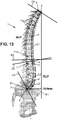
- Fig. 13 shows a lateral patient spine view, with a thoracic kyphosis concentrated in the middle region of thoracic vertebrae, allowing performance of a step of the method of preoperative planning according to an embodiment of the invention.
- Spine curvature should be changed so as to provide for a closer to zero (or better a close to zero) value of sagittal vertical axis.
- the value of lumbar lordosis is on figure 13 is 72.1 degrees.
- the lumbar lordosis is concentrated in the lower region of lumbar vertebrae 2; therefore intermediate marker 8 is closer to end marker 9 than to end marker 7.
- intermediate marker 8 can be moved on the display device by the operator so as to change the curvature of curve C2 between two end markers 7 and 9.
- thoracic kyphosis is on figure 13 is 34.5 degrees.
- the thoracic kyphosis is concentrated in the middle region of thoracic vertebrae 2; therefore intermediate marker 5 is halfway between end markers 4 and 6.
- intermediate marker 5 can be moved on the display device by the operator so as to change the curvature of curve C1 between two end markers 4 and 6.
- the sagittal vertical axis value E1 is -73.5mm. This value should be brought close to zero, if possible and while respecting the scheduled values of lumbar lordosis and thoracic kyphosis for this specific patient, so that spine 1 becomes more balanced.
- Fig. 14 shows a lateral patient spine view, with a thoracic kyphosis concentrated in the lower region of thoracic vertebrae, allowing performance of a step of the method of preoperative planning according to an embodiment of the invention.
- Spine curvature should be changed so as to provide for a closer to zero (or better a close to zero) value of sagittal vertical axis.
- the value of lumbar lordosis is on figure 14 is 72.1 degrees.
- the lumbar lordosis is concentrated in the lower region of lumbar vertebrae 2; therefore intermediate marker 8 is closer to end marker 9 than to end marker 7.
- intermediate marker 8 can be moved on the display device by the operator so as to change the curvature of curve C2 between two end markers 7 and 9.
- thoracic kyphosis The value of thoracic kyphosis is on figure 14 is 26.5 degrees.
- the thoracic kyphosis is concentrated in the lower region of thoracic vertebrae 2; therefore intermediate marker 5 is closer to end marker 6 than to end marker 4.
- the thoracic kyphosis should not be so concentrated in the lower region of thoracic vertebrae 2 and should be better distributed.
- intermediate marker 5 can be moved on the display device by the operator so as to change the curvature of curve C1 between two end markers 4 and 6.
- the sagittal vertical axis value E1 is -72.9mm. This value should be brought close to zero, if possible and while respecting the scheduled values of lumbar lordosis and thoracic kyphosis for this specific patient, so that spine 1 becomes more balanced.
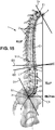
- Fig. 15 shows a lateral patient spine view, with a thoracic kyphosis concentrated in the upper region of thoracic vertebrae, allowing performance of a step of the method of preoperative planning according to an embodiment of the invention.
- Spine curvature should be changed so as to provide for a closer to zero (or better a close to zero) value of sagittal vertical axis.
- the value of lumbar lordosis is on figure 15 is 72.1 degrees.
- the lumbar lordosis is concentrated in the lower region of lumbar vertebrae 2; therefore intermediate marker 8 is closer to end marker 9 than to end marker 7.
- intermediate marker 8 can be moved on the display device by the operator so as to change the curvature of curve C2 between two end markers 7 and 9.
- thoracic kyphosis The value of thoracic kyphosis is on figure 15 is 61.5 degrees.
- the thoracic kyphosis is concentrated in the upper region of thoracic vertebrae 2; therefore intermediate marker 5 is closer to end marker 4 than to end marker 6.
- the thoracic kyphosis should not be so concentrated in the upper region of thoracic vertebrae 2 and should be better distributed.
- intermediate marker 5 can be moved on the display device by the operator so as to change the curvature of curve C1 between two end markers 4 and 6.
- the sagittal vertical axis value E1 is -68.7mm. This value should be brought close to zero, if possible and while respecting the scheduled values of lumbar lordosis and thoracic kyphosis for this specific patient, so that spine 1 becomes more balanced.
Landscapes
- Health & Medical Sciences (AREA)
- Life Sciences & Earth Sciences (AREA)
- Orthopedic Medicine & Surgery (AREA)
- Engineering & Computer Science (AREA)
- Surgery (AREA)
- Medical Informatics (AREA)
- Veterinary Medicine (AREA)
- Biomedical Technology (AREA)
- Heart & Thoracic Surgery (AREA)
- Nuclear Medicine, Radiotherapy & Molecular Imaging (AREA)
- Molecular Biology (AREA)
- Animal Behavior & Ethology (AREA)
- General Health & Medical Sciences (AREA)
- Public Health (AREA)
- Neurology (AREA)
- Physics & Mathematics (AREA)
- Radiology & Medical Imaging (AREA)
- Pathology (AREA)
- Biophysics (AREA)
- High Energy & Nuclear Physics (AREA)
- Optics & Photonics (AREA)
- Robotics (AREA)
- Dentistry (AREA)
- Oral & Maxillofacial Surgery (AREA)
- Physiology (AREA)
- Computer Vision & Pattern Recognition (AREA)
- Measuring And Recording Apparatus For Diagnosis (AREA)
- Orthopedics, Nursing, And Contraception (AREA)
- Measurement Of The Respiration, Hearing Ability, Form, And Blood Characteristics Of Living Organisms (AREA)
Description
- The invention relates to a method of preoperative planning to correct spine misalignment of a patient and to the associated pre-shaped or pre-twisted rod, to be integrated within a patient body to support a patient spine, which has been pre-shaped or pre-twisted according to position and orientation of a set of imaged vertebrae after a step of making a translation and a rotation in a sagittal plane performed during such a method of preoperative planning to correct spine misalignment of a patient.
- According to a prior art, it is known a method of preoperative planning to correct spine misalignment of a patient based on a step of making a translation and a rotation, in a sagittal plane, of each vertebra of a set of several cervical and/or thoracic and/or lumbar imaged spine vertebrae, so that said set of imaged vertebrae presents afterwards, in the sagittal plane, the same cervical lordosis and/or the same thoracic kyphosis and/or the same lumbar lordosis as a model adapted for said patient.
- Unfortunately, in this prior art, the translation and rotation performed in the sagittal plane lead to an associated pre-twisted rod to be integrated within a patient body to support a patient spine, which has been pre-twisted according to position and orientation of a set of imaged vertebrae after a step of making a translation and a rotation in a sagittal plane performed during such a method of preoperative planning to correct spine misalignment of a patient which lacks precision as to its length and as to its curvature location.
- Indeed, the length of the rod is not the correct one, and if cervical lordosis and/or thoracic kyphosis and/or lumbar lordosis present correct curvatures, these curvatures are not located at the right place, specific points of these curvatures, like for example maximum points, minimum points, inflexion points, are shifted and located at the wrong parts of the vertebrae if not at the wrong vertebrae.
- Therefore, during subsequent operative treatment, the surgeon will need re-twisting empirically, maybe in an iterative way, this pre-twisted rod so as to fit it correctly to the patient.
-
US2015100091 discloses a method provided for correcting a curvature or deformity in a patient's spine based on the digitized locations of implanted screws and tracking the placement of the rod as it is placed in a minimally invasive fashion. The method is implemented by a control unit through a GUI to digitize screw locations, accept one or more correction outputs, and generate one or more rod solution outputs shaped to fit at locations distinct from the implanted screw locations. - The invention is defined in the appended claims.
- The object of the present invention is to alleviate at least partly the above mentioned drawbacks.
- More particularly, the invention aims to provide for a more precise method of preoperative planning to correct spine misalignment of a patient leading to an associated pre-twisted rod presenting a more precise length and/or a more precise location of at least one of the curvatures of cervical lordosis and/or thoracic kyphosis and/or lumbar lordosis, preferably presenting a more precise length and a more precise location of at least of the curvatures of all imaged and studied spine portions among cervical lordosis and/or thoracic kyphosis and/or lumbar lordosis.
- Therefore, the invention proposes, before the step of making translation and rotation in a sagittal plane of the imaged spine vertebrae, to make a translation and a rotation, in a coronal plane, of the imaged spine vertebrae so as to make them straight in the coronal plane, and a rotation, in an axial plane, of the imaged spine vertebrae so as to make them axially aligned.
- This way, the step of making translation and rotation in a sagittal plane of the imaged spine vertebrae can be performed on an imaged spine already corrected from scoliosis and from axial vertebrae misalignment.
- The correct cervical lordosis and/or thoracic kyphosis and/or lumbar lordosis may then be implemented on an imaged spine presenting already a straight axis in the coronal plane and an axially aligned imaged spine in the axial plane. The obtained pre-twisted rod is then much more precise, in length and/or in curvature location, having been manufactured or deformed according to a completely correctly amended imaged spine and not according to a partly correctly amended imaged spine as in prior art.
- This object is achieved with a method of preoperative planning to correct spine misalignment of a patient, comprising a step of making a translation and a rotation, in a sagittal plane, of each vertebra of a set of several cervical and/or thoracic and/or lumbar imaged spine vertebrae, so that said set of imaged vertebrae presents afterwards, in the sagittal plane, the same cervical lordosis and/or the same thoracic kyphosis and/or the same lumbar lordosis as a model adapted for said patient, wherein it also comprises, before said step of making said translation and said rotation in a sagittal plane: a step of making a translation and a rotation, in a coronal plane, of each vertebra of said set of several cervical and/or thoracic and/or lumbar imaged spine vertebrae, so that said set of imaged vertebrae becomes straight in said coronal plane, and of making a rotation, in an axial plane, of each vertebra of said set of several cervical and/or thoracic and/or lumbar imaged spine vertebrae, so that said set of imaged vertebrae becomes axially aligned.
- Making a translation and a rotation, in a coronal plane, of each vertebra, and making a rotation, in an axial plane, of each vertebra, may be performed either successively in two successive steps or simultaneously within the same step. When performed successively in two successive steps, the step of making a translation and a rotation, in a coronal plane, of each vertebra, may be performed before the step of making a rotation, in an axial plane, of each vertebra. When performed successively in two successive steps, the step of making a translation and a rotation, in an axial plane, of each vertebra, may be performed before the step of making a rotation, in a coronal plane, of each vertebra. Preferably, the translation in the coronal plan is performed with the first rotation, either the one in coronal plan or the one in axial plan. It is also possible, although less efficient, to perform each step separately, in whatever order, one step being a translation in coronal plan, one other step being a rotation in axial plan, still one other step being a rotation in axial plan.
- This method of preoperative planning to correct spine misalignment of a patient, means that the steps of making translations and rotations, in different planes, of imaged vertebrae, are indeed steps of making translations and rotations of elements or parts of images, on a display device as for example on a screen. Only portions of images or elements within images are translated and/or rotated on a display device during this preoperative planning; no real vertebrae of a patient spine are examined, touched or moved during this preoperative planning.
- This object is also achieved with a method of preoperative planning to correct spine misalignment of a patient, comprising a step of making a translation and a rotation, in a sagittal plane, of each vertebra of a set of several thoracic and/or lumbar imaged spine vertebrae, so that said set of imaged vertebrae presents afterwards, in the sagittal plane, the same thoracic kyphosis and/or the same lumbar lordosis as a model adapted for said patient, wherein it also comprises, before said step of making said translation and said rotation in a sagittal plane, successively: a step of making a translation and a rotation, in a coronal plane, of each vertebra of said set of several thoracic and/or lumbar imaged spine vertebrae, so that said set of imaged vertebrae becomes straight in said coronal plane, a step of making a rotation, in an axial plane, of each vertebra of said set of several thoracic and/or lumbar imaged spine vertebrae, so that said set of imaged vertebrae becomes axially aligned.
- Preferred embodiments comprise one or more of the following features, which can be taken separately or together, either in partial combination or in full combination.
- Preferably, the method of preoperative planning to correct spine misalignment of a patient according to the invention is applied to a set of several thoracic and several lumbar imaged spine vertebrae, so that said set of imaged vertebrae presents, in the sagittal plane, the same thoracic kyphosis and the same lumbar lordosis as a model adapted for said patient. This way, the preoperative planning to correct spine misalignment of a patient and the associated pre-twisted rod will encompass a key part of patient spine, including both thoracic and lumbar vertebrae.
- Preferably, the method of preoperative planning to correct spine misalignment of a patient according to the invention is applied to all thoracic and all lumbar spine vertebrae, so that said patient spine presents, in the sagittal plane, the same thoracic kyphosis and the same lumbar lordosis as a model adapted for said patient. This way, the preoperative planning to correct spine misalignment of a patient and the associated pre-twisted rod will encompass most of patient spine, including all thoracic and all lumbar vertebrae.
- Preferably, in said step of making a translation and a rotation in said coronal plane, said translation and rotation are performed simultaneously, in said step of making a translation and a rotation in said sagittal plane, said translation and rotation are performed simultaneously. This is more efficient and more realistic to perform both translation and rotation of an imaged vertebra at the same time, since afterwards during operative treatment; the surgeon will perform those vertebra moves at the same time on the real vertebrae of the patient spine to effectively correct this patient spine misalignment.
- Preferably, the method of preoperative planning to correct spine misalignment of a patient according to the invention also comprises, after said steps of making translations and rotations: a step of pre-twisting at least one rod, to be integrated within said patient body to support said patient spine, according to position and orientation of said set of imaged vertebrae after said step of making said translation and said rotation in a sagittal plane. Indeed, knowing position and orientation both of the misaligned starting imaged spine and of the corrected final imaged spine, the length and curvature(s) of the needed rod, to maintain corrected spine in its corrected position and orientation after such correction has been performed by the surgeon, can be deduced therefrom. Then, manufacturing or twisting a premanufactured rod so as to make it a pre-twisted rod can be performed according to the deduced length and curvature(s).
- Preferably, in said step of pre-twisting, two rods are pre-twisted which are to be integrated respectively on both sides of said patient spine.
- Preferably, the method of preoperative planning to correct spine misalignment of a patient according to the invention also comprises, after said steps of making translations and rotations: a step of editing a pattern of at least one pre-twisted rod to be integrated within said patient body to support said patient spine, according to position and orientation of said set of imaged vertebrae after said step of making said translation and said rotation in a sagittal plane. With the help of this pattern, starting from a standard rod, either the surgeon or a craftsman can make the dedicated pre-twisted rod(s) to be integrated on the patient spine and preferably on both sides of the patient spine.
- Preferably, the method of preoperative planning to correct spine misalignment of patient according to the invention also comprises, after said steps of making translations and rotations: a step of calculating the length of at least one rod, to be integrated within said patient body to support said patient spine, according to position and orientation of said set of imaged vertebrae after said step of making said translation and said rotation in a sagittal plane. Calculating the exact length is very interesting, because if somewhat too short, the pre-twisted rod will not be as efficient as expected to maintain the corrected position and orientation of patient spine.
- Preferably, said set of several thoracic and/or lumbar imaged spine vertebrae is a 3D spine image reconstructed from two 2D radiographic spine images, preferably from a coronal image and a sagittal image. This way, starting from only 2D radiographic spine imaging, a performing 3D preoperative planning can be made on patient spine, leading to a performing pre-twisted rod correctly deformed in the three dimensional space.
- Preferably, lumbar lordosis position is obtained by moving two end markers corresponding respectively to higher extreme lumbar vertebra and sacral plate and lumbar lordosis curvature is obtained by moving an intermediate marker corresponding to an intermediate lumbar vertebra located between both extreme lumbar vertebrae, and/or thoracic kyphosis position is obtained by moving two end markers corresponding respectively to both extreme thoracic vertebrae, and thoracic kyphosis curvature is obtained by moving an intermediate marker corresponding to an intermediate thoracic vertebra located between both extreme thoracic vertebrae, and/or cervical lordosis position is obtained by moving two end markers corresponding respectively to both extreme cervical vertebrae and cervical lordosis curvature is obtained by moving an intermediate marker corresponding to an intermediate cervical vertebra located between both extreme cervical vertebrae. Such techniques using two end markers and an intermediate marker lead to an optimized compromise between the precision of the curvature(s) implemented and the complexity, both in programing for the planning tool and in manipulation on display for the surgeon, rising with the number of markers. More than three markers, so two end markers and two or more intermediate markers are also possible, but this makes the system more complex for little improved precision.
- Preferably, said model is adapted for said patient first by getting an adapted lordosis from one or more patient based parameters and second by getting an adapted kyphosis from said adapted lordosis and from one or more patient based parameters. The obtained model will be more efficient when lumbar lordosis is adapted first, and when then only, with an optimized and more or less fixed lumbar lordosis (or at most varying within a narrowly limited range), the thoracic kyphosis is adapted.
- Preferably, said adapted lordosis is obtained from patient pelvic incidence and from patient population type and preferably also from patient age. This leads to an optimized compromise between the precision of the curvature(s) implemented and the complexity of calculation to get the right curvature(s).
- Preferably, said adapted kyphosis is obtained from said adapted lordosis and from patient sagittal vertical axis. This leads to an optimized compromise between the precision of the curvature(s) implemented and the complexity of calculation to get the right curvature(s).
- Preferably, said adapted kyphosis is obtained by varying said adapted lordosis curvature within a limited range, preferably plus or minus 10 degrees, while minimizing said patient sagittal vertical axis. This flexibility, allowing to still amend the lumbar lordosis during step of thoracic kyphosis determination after step of lumbar lordosis determination has been completed, such amendment being performed within a narrowly limited range, allows for quicker and more efficient convergence of the thoracic kyphosis than the convergence which would be obtained with a completely fixed value of lumbar lordosis.
- Preferably, said spinal misalignment comes from a scoliosis and/or from a degenerative spine. Those are the diseases which can be corrected thanks to the method of preoperative planning to correct spine misalignment of a patient and/or to the associated pre-twisted rod(s), both according to embodiments of the invention.
- Preferably, there is a pre-twisted rod, to be integrated within a patient body to support a patient spine, which has been pre-twisted according to position and orientation of a set of imaged vertebrae after a step of making a translation and a rotation in a sagittal plane performed during a method of preoperative planning to correct spine misalignment of a patient according to the disclosure. This pre-twisted rod may be used afterwards directly by the surgeon during subsequent operative treatment.
- Further features and advantages of the invention will appear from the following description of embodiments of the invention, given as nonlimiting examples, with reference to the accompanying drawings listed hereunder.
-
-
Fig. 1 shows a frontal patient spine view, the patient suffering from scoliosis, allowing performance of a step of the method of preoperative planning according to an embodiment of the invention. -
Fig. 2 shows a frontal patient spine view, the spine having been partly derotated during preoperative planning, allowing performance of a step of the method of preoperative planning according to an embodiment of the invention. -
Fig. 3 shows a frontal patient spine view, where a starting phase of translation and rotation, in a coronal plane, allowing performance of a step of the method of preoperative planning according to an embodiment of the invention. -
Fig. 4 shows a frontal patient spine view, where an ending phase of translation and rotation, in a coronal plane, allowing performance of a step of the method of preoperative planning according to an embodiment of the invention. -
Fig. 5 shows a frontal patient spine view, where a starting phase of translation and rotation, in an axial plane, allowing performance of a step of the method of preoperative planning according to an embodiment of the invention. -
Fig. 6 shows a frontal patient spine view, where an ending phase of translation and rotation, in an axial plane, allowing performance of a step of the method of preoperative planning according to an embodiment of the invention. -
Fig. 7 shows a lateral patient spine view, with a high value of thoracic kyphosis, allowing performance of a step of the method of preoperative planning according to an embodiment of the invention. -
Fig. 8 shows a lateral patient spine view, with a high value of lumbar lordosis, allowing performance of a step of the method of preoperative planning according to an embodiment of the invention. -
Fig. 9 shows a lateral patient spine view, with a close to zero value of sagittal vertical axis, allowing performance of a step of the method of preoperative planning according to an embodiment of the invention. -
Fig. 10 shows a lateral patient spine view, with a lumbar lordosis concentrated in the middle region of lumbar vertebrae, allowing performance of a step of the method of preoperative planning according to an embodiment of the invention. -
Fig. 11 shows a lateral patient spine view, with a lumbar lordosis concentrated in the lower region of lumbar vertebrae, allowing performance of a step of the method of preoperative planning according to an embodiment of the invention. -
Fig. 12 shows a lateral patient spine view, with a lumbar lordosis concentrated in the upper region of lumbar vertebrae, allowing performance of a step of the method of preoperative planning according to an embodiment of the invention. -
Fig. 13 shows a lateral patient spine view, with a thoracic kyphosis concentrated in the middle region of thoracic vertebrae, allowing performance of a step of the method of preoperative planning according to an embodiment of the invention. -
Fig. 14 shows a lateral patient spine view, with a thoracic kyphosis concentrated in the lower region of thoracic vertebrae, allowing performance of a step of the method of preoperative planning according to an embodiment of the invention. -
Fig. 15 shows a lateral patient spine view, with a thoracic kyphosis concentrated in the upper region of thoracic vertebrae, allowing performance of a step of the method of preoperative planning according to an embodiment of the invention. -
Fig. 1 shows a frontal patient spine view, the patient suffering from scoliosis, allowing performance of a step of the method of preoperative planning according to an embodiment of the invention. - A
patient spine 1 comprisesvertebrae 2 and is ended bypelvis 3.Vertebrae 2 comprise thoracic vertebrae T1 to T12 and lumbar vertebrae L1 to L5. Asane spine 1 should appear as vertical in the coronal plan. Here, one can see that thespine 1 is heavily curved toward left offigure 1 in its upper part, corresponding tothoracic vertebrae 2, and slightly curved toward right offigure 1 in its lower part, corresponding tolumbar vertebrae 2. This means that representedspine 1 suffers from a disease called scoliosis. This means that representedspine 1 should be made straight in coronal plan. Therefore, imaged thoracic vertebrae T1 to T12 should be moved to the right offigure 1 , whereas imaged lumbar vertebrae L1 to L5 should be moved to the left offigure 1 . -
Fig. 2 shows a frontal patient spine view, the spine having been partly derotated during preoperative planning, allowing performance of a step of the method of preoperative planning according to an embodiment of the invention. - The
thoracic vertebrae 2 comprise thoracic vertebrae T1, T2, T3, T4, T5, T6, T7, T8, T9, T10, T11, T12. Thelumbar vertebrae 2 comprise lumbar vertebrae L1, L2, L3, L4, L5. Thespine 1 is straight, what means allvertebrae 2 are vertically aligned. The representedspine 1 is a sane spine with respect to coronal plan. So, thespine 1, represented onfigure 1 , suffering from scoliosis, should be healed so as to become thestraight spine 1 in coronal plan offigure 2 , appearing to be sane with respect to coronal plan. Therefore, all imagedvertebrae 2 offigure 1 will have to be derotated, i.e. to undergo a derotation, so as to become straight in coronal plan as onfigure 2 . This derotation will include indeed a rotation and a translation to be performed simultaneously. -
Fig. 3 shows a frontal patient spine view, where a starting phase of translation and rotation, in a coronal plane, allowing performance of a step of the method of preoperative planning according to an embodiment of the invention. During derotation, intervertebral space is maintained. - One by one, each
vertebra 2 will be simultaneously translated and rotated in the coronal plan offigure 3 , so that thespine 1 becomes straight in coronal plan offigure 3 . Onfigure 3 , lumbar vertebrae L5 to L1 and thoracic vertebra T12 have already undergone such combined translation and rotation in coronal plan and are already vertically aligned in coronal plan. Thoracic vertebra T11 has just started its combined translation and rotation in coronal plan. Thoracic vertebrae T10 to T1 are still in their original position corresponding to scoliosis ofspine 1, waiting for derotation. -
Fig. 4 shows a frontal patient spine view, where an ending phase of translation and rotation, in a coronal plane, allowing performance of a step of the method of preoperative planning according to an embodiment of the invention. - On
figure 4 , lumbar vertebrae L5 to L1 and thoracic vertebra T12 have already undergone such combined translation and rotation in coronal plan and are already vertically aligned in coronal plan. Thoracic vertebra T11 is about ending its combined translation and rotation in coronal plan. Thoracic vertebrae T10 to T1 are still in their original position corresponding to scoliosis ofspine 1, waiting for derotation. -
Fig. 5 shows a frontal patient spine view, where a starting phase of translation and rotation, in an axial plane, allowing performance of a step of the method of preoperative planning according to an embodiment of the invention. - One by one, each
vertebra 2 will be simultaneously translated and rotated in the axial plan offigure 5 , so that thespine 1 becomes straight in axial plan offigure 5 . Onfigure 5 , lumbar vertebrae L5 to L1 and thoracic vertebra T12 to T9 have already undergone such combined translation and rotation in axial plan and are already vertically aligned in axial plan. Thoracic vertebra T8 has just started its combined translation and rotation in axial plan. Thoracic vertebrae T7 to T1 are still in their original position corresponding to scoliosis ofspine 1, waiting for derotation. -
Fig. 6 shows a frontal patient spine view, where an ending phase of translation and rotation, in an axial plane, allowing performance of a step of the method of preoperative planning according to an embodiment of the invention. - On
figure 6 , lumbar vertebrae L5 to L1 and thoracic vertebra T12 to T9 have already undergone such combined translation and rotation in axial plan and are already vertically aligned in axial plan. Thoracic vertebra T8 is ending its combined translation and rotation in axial plan. Thoracic vertebrae T7 to T1 are still in their original position corresponding to scoliosis ofspine 1, waiting for derotation. -
Figures 3-6 have shown both derotations in coronal plan and in axial plan. In fact, both derotations may be performed the following way: combined translation in coronal plan and rotations respectively in coronal and axial plans are performed either successively or simultaneously with the imagedvertebrae 2 on display device during preoperative planning so that, at the end,spine 1 becomes aligned in coronal and axial plans, in a similar way as will be made with the real vertebrae later during operative treatment. -
Fig. 7 shows a lateral patient spine view, with a high value of thoracic kyphosis, allowing performance of a step of the method of preoperative planning according to an embodiment of the invention. Spine curvature should be changed so as to provide for a closer to zero (or better a close to zero) value of sagittal vertical axis. -
Spine 1 is articulated on sacral plate S1 ofpelvis 3 and comprisesvertebrae 2 among which thoracic vertebrae T1 to T12 and lumbar vertebrae L1 to L5. The lumbar lordosis is the curvature of curve C2 ofspine 1 on a subset of lumbar vertebrae L1 to L5. It can be determined as the angle between two directions D1 and D2 which correspond respectively to sacral plate S1 of pelvis orientation and to upper plate of lumbar vertebra L1 orientation. Its value onfigure 7 is 71.4 degrees. - To change the value of lumbar lordosis, an
intermediate marker 8 can be moved on the display device by the operator so as to change the curvature of curve C2 between twoend markers pelvis 3. By moving theintermediate marker 8, the curve C2 is also displaced, sinceintermediate marker 8 stays on this curve C2. - The
intermediate marker 8 can be moved up and down alongspine 1 axis in order to change curvature distribution as well as perpendicularly tospine 1 axis in order to change curvature direction and curvature amplitude. The bounds of thisintermediate marker 8 displacement are alongspine 1 axis the extreme lumbar vertebrae L1 and L5, and perpendicularly tospine 1 axis the maximum amplitude corresponding to maximal curvature that the lumbar vertebrae L1 to L5 may bear without damage. - The thoracic kyphosis is the curvature of curve C1 of
spine 1 on a subset of thoracic vertebrae T1 to T12. It can be determined as the angle between two directions D3 and D4 which correspond respectively to lower plate of thoracic vertebra T12 orientation and to upper plate of thoracic vertebra T1 orientation. Its value onfigure 7 is 50.7 degrees. - To change the value of thoracic kyphosis, an
intermediate marker 5 can be moved on the display device by the operator so as to change the curvature of curve C1 between twoend markers intermediate marker 5, the curve C1 is also displaced, sinceintermediate marker 5 stays on this curve C1. - The
intermediate marker 5 can be moved up and down alongspine 1 axis in order to change curvature distribution as well as perpendicularly tospine 1 axis in order to change curvature direction and curvature amplitude. The bounds of thisintermediate marker 5 displacement are alongspine 1 axis the extreme thoracic vertebrae T1 and T12, and perpendicularly tospine 1 axis the maximum amplitude corresponding to maximal curvature that the thoracic vertebrae T1 to T12 may bear without damage. - The sagittal vertical axis value E1 is -115.4mm. This value should be brought close to zero, if possible and while respecting the scheduled values of lumbar lordosis and thoracic kyphosis for this specific patient, so that
spine 1 becomes more balanced and may correspond to saner thoracic kyphosis and lumbar lordosis. Onfigure 7 , the value of thoracic kyphosis, which is too high, should therefore be reduced. -
Fig. 8 shows a lateral patient spine view, with a high value of lumbar lordosis, allowing performance of a step of the method of preoperative planning according to an embodiment of the invention. Spine curvature should be changed so as to provide for a closer to zero (or better a close to zero) value of sagittal vertical axis. - The value of lumbar lordosis is on
figure 8 is 91.1 degrees. To change the value of lumbar lordosis, anintermediate marker 8 can be moved on the display device by the operator so as to change the curvature of curve C2 between twoend markers pelvis 3. By moving theintermediate marker 8, the curve C2 is also displaced, sinceintermediate marker 8 stays on this curve C2. - The value of thoracic kyphosis is on
figure 8 is 41.0 degrees. To change the value of thoracic kyphosis, anintermediate marker 5 can be moved on the display device by the operator so as to change the curvature of curve C1 between twoend markers intermediate marker 5, the curve C1 is also displaced, sinceintermediate marker 5 stays on this curve C1. - The sagittal vertical axis value E1 is 4.2mm. This value should be brought close to zero, if possible and while respecting the scheduled values of lumbar lordosis and thoracic kyphosis for this specific patient, so that
spine 1 becomes more balanced and may correspond to saner thoracic kyphosis and lumbar lordosis. Onfigure 8 , the value of lumbar lordosis, which is too high, should therefore be reduced. -
Fig. 9 shows a lateral patient spine view, with a close to zero value of sagittal vertical axis, allowing performance of a step of the method of preoperative planning according to an embodiment of the invention. Spine curvature is adapted because the value of sagittal vertical axis is already close to zero. - The value of lumbar lordosis is on
figure 9 is 86.0 degrees. To change the value of lumbar lordosis, anintermediate marker 8 can be moved on the display device by the operator so as to change the curvature of curve C2 between twoend markers - The value of thoracic kyphosis is on
figure 9 is 34.5 degrees. To change the value of thoracic kyphosis, anintermediate marker 5 can be moved on the display device by the operator so as to change the curvature of curve C1 between twoend markers - The sagittal vertical axis value E1 is -1.5mm. This value is indeed very close to zero. On
figure 9 , correspondingspine 1 is well balanced and corresponds to sane thoracic kyphosis and lumbar lordosis. -
Fig. 10 shows a lateral patient spine view, with a lumbar lordosis concentrated in the middle region of lumbar vertebrae, allowing performance of a step of the method of preoperative planning according to an embodiment of the invention. Spine curvature should be changed so as to provide for a closer to zero (or better a close to zero) value of sagittal vertical axis. - The value of lumbar lordosis is on
figure 10 is 76.4 degrees. The lumbar lordosis is concentrated in the middle region oflumbar vertebrae 2; thereforeintermediate marker 8 is halfway betweenend markers intermediate marker 8 can be moved on the display device by the operator so as to change the curvature of curve C2 between twoend markers - The value of thoracic kyphosis is on
figure 10 is 34.5 degrees. The thoracic kyphosis is concentrated in the middle region ofthoracic vertebrae 2; thereforeintermediate marker 5 is halfway betweenend markers intermediate marker 5 can be moved on the display device by the operator so as to change the curvature of curve C1 between twoend markers - The sagittal vertical axis value E1 is -53.1mm. This value should be brought close to zero, if possible and while respecting the scheduled values of lumbar lordosis and thoracic kyphosis for this specific patient, so that
spine 1 becomes more balanced. -
Fig. 11 shows a lateral patient spine view, with a lumbar lordosis concentrated in the lower region of lumbar vertebrae, allowing performance of a step of the method of preoperative planning according to an embodiment of the invention. Spine curvature should be changed so as to provide for a closer to zero (or better a close to zero) value of sagittal vertical axis. - The value of lumbar lordosis is on
figure 11 is 68.0 degrees. The lumbar lordosis is concentrated in the lower region oflumbar vertebrae 2; thereforeintermediate marker 8 is closer to endmarker 9 than to endmarker 7. The lumbar lordosis should not be so concentrated in the lower region oflumbar vertebrae 2 and should be better distributed. To change the value of lumbar lordosis,intermediate marker 8 can be moved on the display device by the operator so as to change the curvature of curve C2 between twoend markers - The value of thoracic kyphosis is on
figure 11 is 34.5 degrees. The thoracic kyphosis is concentrated in the middle region ofthoracic vertebrae 2; thereforeintermediate marker 5 is halfway betweenend markers intermediate marker 5 can be moved on the display device by the operator so as to change the curvature of curve C1 between twoend markers - The sagittal vertical axis value E1 is -91.8mm. This value should be brought close to zero, if possible and while respecting the scheduled values of lumbar lordosis and thoracic kyphosis for this specific patient, so that
spine 1 becomes more balanced. -
Fig. 12 shows a lateral patient spine view, with a lumbar lordosis concentrated in the upper region of lumbar vertebrae, allowing performance of a step of the method of preoperative planning according to an embodiment of the invention. Spine curvature should be changed so as to provide for a closer to zero (or better a close to zero) value of sagittal vertical axis. - The value of lumbar lordosis is on
figure 12 is 74.4 degrees. The lumbar lordosis is concentrated in the upper region oflumbar vertebrae 2; thereforeintermediate marker 8 is closer to endmarker 7 than to endmarker 9. The lumbar lordosis should not be so concentrated in the upper region oflumbar vertebrae 2 and should be better distributed. To change the value of lumbar lordosis,intermediate marker 8 can be moved on the display device by the operator so as to change the curvature of curve C2 between twoend markers - The value of thoracic kyphosis is on
figure 12 is 34.5 degrees. The thoracic kyphosis is concentrated in the middle region ofthoracic vertebrae 2; thereforeintermediate marker 5 is halfway betweenend markers intermediate marker 5 can be moved on the display device by the operator so as to change the curvature of curve C1 between twoend markers - The sagittal vertical axis value E1 is -61.7mm. This value should be brought close to zero, if possible and while respecting the scheduled values of lumbar lordosis and thoracic kyphosis for this specific patient, so that
spine 1 becomes more balanced. -
Fig. 13 shows a lateral patient spine view, with a thoracic kyphosis concentrated in the middle region of thoracic vertebrae, allowing performance of a step of the method of preoperative planning according to an embodiment of the invention. Spine curvature should be changed so as to provide for a closer to zero (or better a close to zero) value of sagittal vertical axis. - The value of lumbar lordosis is on
figure 13 is 72.1 degrees. The lumbar lordosis is concentrated in the lower region oflumbar vertebrae 2; thereforeintermediate marker 8 is closer to endmarker 9 than to endmarker 7. To change the value of lumbar lordosis,intermediate marker 8 can be moved on the display device by the operator so as to change the curvature of curve C2 between twoend markers - The value of thoracic kyphosis is on
figure 13 is 34.5 degrees. The thoracic kyphosis is concentrated in the middle region ofthoracic vertebrae 2; thereforeintermediate marker 5 is halfway betweenend markers intermediate marker 5 can be moved on the display device by the operator so as to change the curvature of curve C1 between twoend markers - The sagittal vertical axis value E1 is -73.5mm. This value should be brought close to zero, if possible and while respecting the scheduled values of lumbar lordosis and thoracic kyphosis for this specific patient, so that
spine 1 becomes more balanced. -
Fig. 14 shows a lateral patient spine view, with a thoracic kyphosis concentrated in the lower region of thoracic vertebrae, allowing performance of a step of the method of preoperative planning according to an embodiment of the invention. Spine curvature should be changed so as to provide for a closer to zero (or better a close to zero) value of sagittal vertical axis. - The value of lumbar lordosis is on
figure 14 is 72.1 degrees. The lumbar lordosis is concentrated in the lower region oflumbar vertebrae 2; thereforeintermediate marker 8 is closer to endmarker 9 than to endmarker 7. To change the value of lumbar lordosis,intermediate marker 8 can be moved on the display device by the operator so as to change the curvature of curve C2 between twoend markers - The value of thoracic kyphosis is on
figure 14 is 26.5 degrees. The thoracic kyphosis is concentrated in the lower region ofthoracic vertebrae 2; thereforeintermediate marker 5 is closer to endmarker 6 than to endmarker 4. The thoracic kyphosis should not be so concentrated in the lower region ofthoracic vertebrae 2 and should be better distributed. To change the value of thoracic kyphosis,intermediate marker 5 can be moved on the display device by the operator so as to change the curvature of curve C1 between twoend markers - The sagittal vertical axis value E1 is -72.9mm. This value should be brought close to zero, if possible and while respecting the scheduled values of lumbar lordosis and thoracic kyphosis for this specific patient, so that
spine 1 becomes more balanced. -
Fig. 15 shows a lateral patient spine view, with a thoracic kyphosis concentrated in the upper region of thoracic vertebrae, allowing performance of a step of the method of preoperative planning according to an embodiment of the invention. Spine curvature should be changed so as to provide for a closer to zero (or better a close to zero) value of sagittal vertical axis. - The value of lumbar lordosis is on
figure 15 is 72.1 degrees. The lumbar lordosis is concentrated in the lower region oflumbar vertebrae 2; thereforeintermediate marker 8 is closer to endmarker 9 than to endmarker 7. To change the value of lumbar lordosis,intermediate marker 8 can be moved on the display device by the operator so as to change the curvature of curve C2 between twoend markers - The value of thoracic kyphosis is on
figure 15 is 61.5 degrees. The thoracic kyphosis is concentrated in the upper region ofthoracic vertebrae 2; thereforeintermediate marker 5 is closer to endmarker 4 than to endmarker 6. The thoracic kyphosis should not be so concentrated in the upper region ofthoracic vertebrae 2 and should be better distributed. To change the value of thoracic kyphosis,intermediate marker 5 can be moved on the display device by the operator so as to change the curvature of curve C1 between twoend markers - The sagittal vertical axis value E1 is -68.7mm. This value should be brought close to zero, if possible and while respecting the scheduled values of lumbar lordosis and thoracic kyphosis for this specific patient, so that
spine 1 becomes more balanced. - The invention has been described with reference to preferred embodiments. However, many variations are possible within the scope of the invention.
Claims (15)
- Method of preoperative planning to correct spine (1) misalignment of a patient, comprising a step of making a translation and a rotation, in a sagittal plane, of each vertebra (2) of a set of several cervical and/or thoracic (T1-T12) and/or lumbar (L1-L5) imaged spine vertebrae (2), so that said set of imaged vertebrae (2) presents afterwards, in the sagittal plane, the same cervical lordosis and/or the same thoracic kyphosis and/or the same lumbar lordosis as a model adapted for said patient,
wherein it also comprises, before said step of making said translation and said rotation in a sagittal plane a step of making a translation and a rotation, in a coronal plane, of each vertebra (2) of said set of several cervical and/or thoracic (T1-T12) and/or lumbar (L1-L5) imaged spine vertebrae (2), so that said set of imaged vertebrae (2) becomes straight in said coronal plane, and of making a rotation, in an axial plane, of each vertebra (2) of said set of several cervical and/or thoracic (T1-T12) and/or lumbar (L1-L5) imaged spine vertebrae (2), so that said set of imaged vertebrae (2) becomes axially aligned. - Method of preoperative planning to correct spine (1) misalignment of a patient according to claim 1, wherein it is applied to a set of several thoracic (T1-T12) and several lumbar (L1-L5) imaged spine vertebrae (2), so that said set of imaged vertebrae (2) presents, in the sagittal plane, the same thoracic kyphosis and the same lumbar lordosis as a model adapted for said patient.
- Method of preoperative planning to correct spine (1) misalignment of a patient according to claim 2, wherein it is applied to all thoracic (T1-T12) and all lumbar (L1-L5) spine vertebrae (2), so that said patient spine (1) presents, in the sagittal plane, the same thoracic kyphosis and the same lumbar lordosis as a model adapted for said patient.
- Method of preoperative planning to correct spine (1) misalignment of a patient according to any of claims 1 to 3, wherein:- in said step of making a translation and a rotation in said coronal plane, said translation and rotation are performed simultaneously,- in said step of making a translation and a rotation in said sagittal plane, said translation and rotation are performed simultaneously.
- Method of preoperative planning to correct spine (1) misalignment of a patient according to any of preceding claims, wherein it also comprises, after said steps of making translations and rotations, a step of pre-twisting at least one rod, to be integrated within said patient body to support said patient spine (1), according to position and orientation of said set of imaged vertebrae (2) after said step of making said translation and said rotation in a sagittal plane.
- Method of preoperative planning to correct spine (1) misalignment of a patient according to claim 5, wherein in said step of pre-twisting, two rods are pre-twisted which are to be integrated respectively on both sides of said patient spine (1).
- Method of preoperative planning to correct spine (1) misalignment of a patient according to any of claims 1 to 4, wherein it also comprises, after said steps of making translations and rotations, a step of editing a pattern of at least one pre-twisted rod to be integrated within said patient body to support said patient spine (1), according to position and orientation of said set of imaged vertebrae (2) after said step of making said translation and said rotation in a sagittal plane.
- Method of preoperative planning to correct spine (1) misalignment of a patient according to any of preceding claims, wherein it also comprises, after said steps of making translations and rotations, a step of calculating the length of at least one rod, to be integrated within said patient body to support said patient spine (1), according to position and orientation of said set of imaged vertebrae (2) after said step of making said translation and said rotation in a sagittal plane.
- Method of preoperative planning to correct spine (1) misalignment of a patient according to any of preceding claims, wherein said set of several thoracic (T1-T12) and/or lumbar (L1-L5) imaged spine vertebrae (2) is a 3D spine (1) image reconstructed from two 2D radiographic spine (1) images, preferably from a coronal image and a sagittal image.
- Method of preoperative planning to correct spine (1) misalignment of a patient according to any of preceding claims,wherein lumbar lordosis position is obtained by moving two end markers (7, 9) corresponding respectively to higher extreme lumbar vertebra (L1) and sacral plate (S1) and lumbar lordosis curvature (C2) is obtained by moving an intermediate marker (8) corresponding to an intermediate lumbar vertebra located between both extreme lumbar vertebrae (L1-L5),and/or wherein thoracic kyphosis position is obtained by moving two end markers (4, 6) corresponding respectively to both extreme thoracic vertebrae (T1, T12) and thoracic kyphosis curvature (C1) is obtained by moving an intermediate marker (5) corresponding to an intermediate thoracic vertebra located between both extreme thoracic vertebrae (T1, T12),and/or wherein cervical lordosis position is obtained by moving two end markers corresponding respectively to both extreme cervical vertebrae and cervical lordosis curvature is obtained by moving an intermediate marker corresponding to an intermediate cervical vertebra located between both extreme cervical vertebrae.
- Method of preoperative planning to correct spine (1) misalignment of a patient according to any of preceding claims, wherein said model is adapted for said patient first by getting an adapted lordosis from one or more patient based parameters and second by getting an adapted kyphosis from said adapted lordosis and from one or more patient based parameters.
- Method of preoperative planning to correct spine (1) misalignment of a patient according to claim 11, wherein said adapted lordosis is obtained from patient pelvic incidence and from patient population type and preferably also from patient age.
- Method of preoperative planning to correct spine (1) misalignment of a patient according to claim 12, wherein said adapted kyphosis is obtained from said adapted lordosis and from patient sagittal vertical axis (E1).
- Method of preoperative planning to correct spine (1) misalignment of a patient according to claim 13, wherein said adapted kyphosis is obtained by varying said adapted lordosis curvature (C2) within a limited range, preferably plus or minus 10 degrees, while minimizing said patient sagittal vertical axis (E1).
- Method of preoperative planning to correct spine (1) misalignment of a patient according to any of preceding claims, wherein said spine (1) misalignment comes from a scoliosis and/or from a degenerative spine.
Applications Claiming Priority (1)
| Application Number | Priority Date | Filing Date | Title |
|---|---|---|---|
| PCT/IB2015/002497 WO2017085529A1 (en) | 2015-11-19 | 2015-11-19 | Method of preoperative planning to correct spine misalignment of a patient |
Publications (2)
| Publication Number | Publication Date |
|---|---|
| EP3376987A1 EP3376987A1 (en) | 2018-09-26 |
| EP3376987B1 true EP3376987B1 (en) | 2020-10-28 |
Family
ID=55236819
Family Applications (1)
| Application Number | Title | Priority Date | Filing Date |
|---|---|---|---|
| EP15828659.1A Active EP3376987B1 (en) | 2015-11-19 | 2015-11-19 | Method of preoperative planning to correct spine misalignment of a patient |
Country Status (4)
| Country | Link |
|---|---|
| US (1) | US11141221B2 (en) |
| EP (1) | EP3376987B1 (en) |
| AU (1) | AU2015414802B2 (en) |
| WO (1) | WO2017085529A1 (en) |
Families Citing this family (43)
| Publication number | Priority date | Publication date | Assignee | Title |
|---|---|---|---|---|
| US9968408B1 (en) | 2013-03-15 | 2018-05-15 | Nuvasive, Inc. | Spinal balance assessment |
| FR3010628B1 (en) | 2013-09-18 | 2015-10-16 | Medicrea International | METHOD FOR REALIZING THE IDEAL CURVATURE OF A ROD OF A VERTEBRAL OSTEOSYNTHESIS EQUIPMENT FOR STRENGTHENING THE VERTEBRAL COLUMN OF A PATIENT |
| WO2015054543A1 (en) | 2013-10-09 | 2015-04-16 | Nuvasive, Inc. | Surgical spinal correction |
| FR3012030B1 (en) | 2013-10-18 | 2015-12-25 | Medicrea International | METHOD FOR REALIZING THE IDEAL CURVATURE OF A ROD OF A VERTEBRAL OSTEOSYNTHESIS EQUIPMENT FOR STRENGTHENING THE VERTEBRAL COLUMN OF A PATIENT |
| US10709509B2 (en) | 2014-06-17 | 2020-07-14 | Nuvasive, Inc. | Systems and methods for planning, performing, and assessing spinal correction during surgery |
| US10695099B2 (en) | 2015-02-13 | 2020-06-30 | Nuvasive, Inc. | Systems and methods for planning, performing, and assessing spinal correction during surgery |
| GB2536650A (en) | 2015-03-24 | 2016-09-28 | Augmedics Ltd | Method and system for combining video-based and optic-based augmented reality in a near eye display |
| US10595941B2 (en) * | 2015-10-30 | 2020-03-24 | Orthosensor Inc. | Spine measurement system and method therefor |
| US10463433B2 (en) | 2016-03-02 | 2019-11-05 | Nuvasive, Inc. | Systems and methods for spinal correction surgical planning |
| WO2018109556A1 (en) | 2016-12-12 | 2018-06-21 | Medicrea International | Systems and methods for patient-specific spinal implants |
| EP3612122B1 (en) | 2017-04-21 | 2023-12-20 | Medicrea International | A system for developing one or more patient-specific spinal implants |
| JP6778242B2 (en) | 2017-11-09 | 2020-10-28 | グローバス メディカル インコーポレイティッド | Surgical robot systems for bending surgical rods, and related methods and equipment |
| US12544109B2 (en) | 2017-11-09 | 2026-02-10 | Globus Medical, Inc. | Robotic rod benders and related mechanical and motor housings |
| US10918422B2 (en) | 2017-12-01 | 2021-02-16 | Medicrea International | Method and apparatus for inhibiting proximal junctional failure |
| US12458411B2 (en) | 2017-12-07 | 2025-11-04 | Augmedics Ltd. | Spinous process clamp |
| US12521201B2 (en) | 2017-12-07 | 2026-01-13 | Augmedics Ltd. | Spinous process clamp |
| WO2019211741A1 (en) | 2018-05-02 | 2019-11-07 | Augmedics Ltd. | Registration of a fiducial marker for an augmented reality system |
| EP3840683A4 (en) | 2018-07-16 | 2022-06-29 | Medtronic Sofamor Danek USA, Inc. | Spinal surgery outcome prediction |
| US11766296B2 (en) | 2018-11-26 | 2023-09-26 | Augmedics Ltd. | Tracking system for image-guided surgery |
| US11666384B2 (en) * | 2019-01-14 | 2023-06-06 | Nuvasive, Inc. | Prediction of postoperative global sagittal alignment based on full-body musculoskeletal modeling and posture optimization |
| US12564447B2 (en) | 2019-04-02 | 2026-03-03 | Medicrea International | Systems, methods, and devices for developing patient-specific spinal implants, treatments, operations, and/or procedures |
| WO2020201353A1 (en) | 2019-04-02 | 2020-10-08 | Medicrea International | Systems, methods, and devices for developing patient-specific spinal implants, treatments, operations, and/or procedures |
| US11944385B2 (en) | 2019-04-02 | 2024-04-02 | Medicrea International | Systems and methods for medical image analysis |
| US11925417B2 (en) | 2019-04-02 | 2024-03-12 | Medicrea International | Systems, methods, and devices for developing patient-specific spinal implants, treatments, operations, and/or procedures |
| US11980506B2 (en) | 2019-07-29 | 2024-05-14 | Augmedics Ltd. | Fiducial marker |
| US12178666B2 (en) | 2019-07-29 | 2024-12-31 | Augmedics Ltd. | Fiducial marker |
| JP7317776B2 (en) | 2019-09-04 | 2023-07-31 | グローバス メディカル インコーポレイティッド | Surgical rod and associated controller |
| US11382712B2 (en) | 2019-12-22 | 2022-07-12 | Augmedics Ltd. | Mirroring in image guided surgery |
| US11769251B2 (en) | 2019-12-26 | 2023-09-26 | Medicrea International | Systems and methods for medical image analysis |
| US11389252B2 (en) | 2020-06-15 | 2022-07-19 | Augmedics Ltd. | Rotating marker for image guided surgery |
| US12502163B2 (en) | 2020-09-09 | 2025-12-23 | Augmedics Ltd. | Universal tool adapter for image-guided surgery |
| US12239385B2 (en) | 2020-09-09 | 2025-03-04 | Augmedics Ltd. | Universal tool adapter |
| US12347100B2 (en) | 2020-11-19 | 2025-07-01 | Mazor Robotics Ltd. | Systems and methods for generating virtual images |
| US12340881B2 (en) * | 2021-01-24 | 2025-06-24 | RightDevice Inc. | System and method of processing medical implant device and patient data |
| US12318144B2 (en) * | 2021-06-23 | 2025-06-03 | Medicrea International SA | Systems and methods for planning a patient-specific spinal correction |
| US11896445B2 (en) | 2021-07-07 | 2024-02-13 | Augmedics Ltd. | Iliac pin and adapter |
| US12150821B2 (en) | 2021-07-29 | 2024-11-26 | Augmedics Ltd. | Rotating marker and adapter for image-guided surgery |
| WO2023021451A1 (en) | 2021-08-18 | 2023-02-23 | Augmedics Ltd. | Augmented reality assistance for osteotomy and discectomy |
| WO2023203521A1 (en) | 2022-04-21 | 2023-10-26 | Augmedics Ltd. | Systems and methods for medical image visualization |
| IL319523A (en) | 2022-09-13 | 2025-05-01 | Augmedics Ltd | Augmented reality eyewear for image-guided medical intervention |
| WO2024155964A1 (en) * | 2023-01-20 | 2024-07-25 | Ht Medical, Llc | Systems and methods for surgical three-dimensional mapping and path determination |
| CN118864440B (en) * | 2024-08-15 | 2025-02-25 | 安徽中医药大学第二附属医院(安徽省针灸医院) | Image processing method and system for scoliosis detection |
| CN120000335B (en) * | 2025-04-21 | 2025-08-19 | 辽宁省全无信息技术有限公司 | C-shaped arm navigation positioning system for orthopedic surgery |
Family Cites Families (202)
| Publication number | Priority date | Publication date | Assignee | Title |
|---|---|---|---|---|
| US5172695A (en) * | 1990-09-10 | 1992-12-22 | Cann Christopher E | Method for improved prediction of bone fracture risk using bone mineral density in structural analysis |
| FR2722393B1 (en) * | 1993-08-27 | 1996-08-23 | Martin Jean Raymond | ANCILLARY MATERIAL FOR CORRECTING A VERTEBRAL DEFORMATION |
| US5400800A (en) * | 1993-10-13 | 1995-03-28 | Baltimore Therapeutic Equipment Co. | Device for measuring lumbar spinal movement |
| US5483960A (en) * | 1994-01-03 | 1996-01-16 | Hologic, Inc. | Morphometric X-ray absorptiometry (MXA) |
| US6978166B2 (en) * | 1994-10-07 | 2005-12-20 | Saint Louis University | System for use in displaying images of a body part |
| DE69532829T2 (en) * | 1994-10-07 | 2005-01-27 | St. Louis University | DEVICE FOR USE WITH A SURGICAL NAVIGATION SYSTEM |
| US5582189A (en) * | 1994-10-24 | 1996-12-10 | Pannozzo; Anthony N. | Method for diagnosing the subluxation of a skeletal articulation |
| US5593408A (en) * | 1994-11-30 | 1997-01-14 | Sofamor S.N.C | Vertebral instrumentation rod |
| US5658286A (en) * | 1996-02-05 | 1997-08-19 | Sava; Garard A. | Fabrication of implantable bone fixation elements |
| US6035691A (en) * | 1999-08-10 | 2000-03-14 | Lin; Ruey-Mo | Adjustable rod bending device for a corrective spinal rod which is used in a surgical operation |
| WO2001052190A1 (en) * | 2000-01-14 | 2001-07-19 | Koninklijke Philips Electronics N.V. | Processing method and system for 3-d geometric modeling of the spine |
| FR2803756B1 (en) * | 2000-01-18 | 2004-11-26 | Eurosurgical | CONNECTING ROD FOR SPINAL INSTRUMENTATION |
| US6235028B1 (en) * | 2000-02-14 | 2001-05-22 | Sdgi Holdings, Inc. | Surgical guide rod |
| US6468233B2 (en) * | 2000-06-26 | 2002-10-22 | Gerry Cook | Posture analyzer |
| JP2004510483A (en) * | 2000-10-02 | 2004-04-08 | コーニンクレッカ フィリップス エレクトロニクス エヌ ヴィ | Method and X-ray apparatus for optimally imaging human body structure |
| US8724865B2 (en) * | 2001-11-07 | 2014-05-13 | Medical Metrics, Inc. | Method, computer software, and system for tracking, stabilizing, and reporting motion between vertebrae |
| FR2836818B1 (en) * | 2002-03-05 | 2004-07-02 | Eurosurgical | PROCESS FOR VISUALIZING AND CHECKING THE BALANCE OF A SPINE COLUMN |
| JP3904993B2 (en) * | 2002-08-16 | 2007-04-11 | ファナック株式会社 | Curve interpolation method |
| US7976568B2 (en) * | 2002-08-25 | 2011-07-12 | University Of Hong Kong | Device for correcting spinal deformities |
| AU2003257339A1 (en) * | 2002-08-26 | 2004-03-11 | Orthosoft Inc. | Computer aided surgery system and method for placing multiple implants |
| US7291118B2 (en) * | 2002-09-05 | 2007-11-06 | Biotonix Inc. | Method for determining the risk of developing a skeletal condition |
| WO2004070577A2 (en) * | 2003-02-04 | 2004-08-19 | Z-Kat, Inc. | Interactive computer-assisted surgery system and method |
| DE102004008870A1 (en) * | 2003-03-31 | 2004-10-14 | Anders, Peter, Prof. Dr.-Ing. | Bending method for a workpiece such as a rod or tube for use in e.g. spinal surgery where a target curve is defined about which the rod is bent |
| JP2005169064A (en) * | 2003-05-22 | 2005-06-30 | Sohei Ebara | Surgical device for correction of spinal deformity, and method for using the same |
| US20050148839A1 (en) * | 2003-12-10 | 2005-07-07 | Adi Shechtman | Method for non-invasive measurement of spinal deformity |
| US9393039B2 (en) * | 2003-12-17 | 2016-07-19 | Brainlab Ag | Universal instrument or instrument set for computer guided surgery |
| US20050262911A1 (en) * | 2004-02-06 | 2005-12-01 | Harry Dankowicz | Computer-aided three-dimensional bending of spinal rod implants, other surgical implants and other articles, systems for three-dimensional shaping, and apparatuses therefor |
| WO2005088520A1 (en) * | 2004-03-11 | 2005-09-22 | University Of Cincinnati | Automated spine survey iterative scan technique (assist) |
| US7567834B2 (en) * | 2004-05-03 | 2009-07-28 | Medtronic Navigation, Inc. | Method and apparatus for implantation between two vertebral bodies |
| US20060015042A1 (en) * | 2004-07-15 | 2006-01-19 | Linial Andrew V | Method and apparatus for detection and measurement of scoliosis of the spine |
| US8014625B2 (en) * | 2004-11-10 | 2011-09-06 | Agfa Healthcare | Method of performing measurements on digital images |
| TWI268148B (en) * | 2004-11-25 | 2006-12-11 | Univ Chung Yuan Christian | Image analysis method for vertebral disease which comprises 3D reconstruction method and characteristic identification method of unaligned transversal slices |
| US20090226055A1 (en) * | 2004-12-10 | 2009-09-10 | Harry Dankowicz | Systems and methods for multi-dimensional characterization and classification of spinal shape |
| US7454939B2 (en) * | 2005-01-12 | 2008-11-25 | Depuy Spine, Inc. | Instrument for bending spinal rods used in a spinal fixation system |
| US20060195090A1 (en) * | 2005-02-10 | 2006-08-31 | Loubert Suddaby | Apparatus for and method of aligning a spine |
| ES2318917B1 (en) * | 2005-03-30 | 2010-02-04 | Sdgi Holdings Inc. | SYSTEM FOR THE THREE-DIMENSIONAL CORRECTION OF THE CURVATURE OF THE VERTEBRAL COLUMN IN PROBLEMS OF SCHOLIOSIS BY COPLANAR ALIGNMENT OF THE PEDICULAR SCREWS. |
| EP1903960A2 (en) * | 2005-07-15 | 2008-04-02 | Children's Hospital Medical Center | Apparatus for minimally invasive posterior correction of spinal deformity |
| US7715605B2 (en) * | 2005-09-07 | 2010-05-11 | Siemens Medical Solution Usa, Inc. | Systems and methods for computer aided detection of spinal curvature using images and angle measurements |
| US7657072B2 (en) * | 2005-09-15 | 2010-02-02 | Siemens Medical Solutions Usa, Inc | System and method for automatic extraction of spinal cord from 3D volumetric images |
| US7876938B2 (en) * | 2005-10-06 | 2011-01-25 | Siemens Medical Solutions Usa, Inc. | System and method for whole body landmark detection, segmentation and change quantification in digital images |
| US7903851B2 (en) * | 2005-10-17 | 2011-03-08 | Siemens Medical Solutions Usa, Inc. | Method and system for vertebrae and intervertebral disc localization in magnetic resonance images |
| US20070191856A1 (en) * | 2006-01-31 | 2007-08-16 | Sdgi Holdings, Inc. | Adjustable height spinal distractor |
| US8177843B2 (en) * | 2006-02-16 | 2012-05-15 | Nabil L. Muhanna | Automated pedicle screw rod bender |
| US20070242869A1 (en) * | 2006-04-12 | 2007-10-18 | Eastman Kodak Company | Processing and measuring the spine in radiographs |
| US8676293B2 (en) * | 2006-04-13 | 2014-03-18 | Aecc Enterprises Ltd. | Devices, systems and methods for measuring and evaluating the motion and function of joint structures and associated muscles, determining suitability for orthopedic intervention, and evaluating efficacy of orthopedic intervention |
| WO2007136784A2 (en) * | 2006-05-17 | 2007-11-29 | Nuvasive, Inc. | Surgical trajectory monitoring system and related methods |
| US20120150243A9 (en) * | 2006-08-31 | 2012-06-14 | Catholic Healthcare West (Chw) | Computerized Planning Tool For Spine Surgery and Method and Device for Creating a Customized Guide for Implantations |
| US7894649B2 (en) * | 2006-11-02 | 2011-02-22 | Accuray Incorporated | Target tracking using direct target registration |
| US20080177203A1 (en) * | 2006-12-22 | 2008-07-24 | General Electric Company | Surgical navigation planning system and method for placement of percutaneous instrumentation and implants |
| US20080255615A1 (en) * | 2007-03-27 | 2008-10-16 | Warsaw Orthopedic, Inc. | Treatments for Correcting Spinal Deformities |
| US20080269805A1 (en) * | 2007-04-25 | 2008-10-30 | Warsaw Orthopedic, Inc. | Methods for correcting spinal deformities |
| US8423124B2 (en) * | 2007-05-18 | 2013-04-16 | Siemens Aktiengesellschaft | Method and system for spine visualization in 3D medical images |
| US8660329B2 (en) * | 2007-05-25 | 2014-02-25 | Ecole Nationale Superieure D'arts Et Metiers (Ensam) | Method for reconstruction of a three-dimensional model of a body structure |
| US20090024164A1 (en) * | 2007-06-25 | 2009-01-22 | Neubardt Seth L | System for determining spinal implants |
| US20090088803A1 (en) * | 2007-10-01 | 2009-04-02 | Warsaw Orthopedic, Inc. | Flexible members for correcting spinal deformities |
| EP2162086B1 (en) * | 2007-10-01 | 2019-02-27 | Orthosoft Inc. | Construction of a non-imaged view of an object using acquired images |
| US20090093852A1 (en) * | 2007-10-05 | 2009-04-09 | Hynes Richard A | Spinal stabilization treatment methods for maintaining axial spine height and sagital plane spine balance |
| DE112008002851B4 (en) * | 2007-10-24 | 2018-06-21 | Nuvasive, Inc. | Surgical pathway monitoring system and related procedures |
| US20090149977A1 (en) * | 2007-11-06 | 2009-06-11 | Schendel Stephen A | Methods, systems, and computer program products for shaping medical implants directly from virtual reality models |
| US20090194206A1 (en) * | 2008-01-31 | 2009-08-06 | Jeon Dong M | Systems and methods for wrought nickel/titanium alloy flexible spinal rods |
| US9345517B2 (en) * | 2008-02-02 | 2016-05-24 | Globus Medical, Inc. | Pedicle screw having a removable rod coupling |
| US8007522B2 (en) * | 2008-02-04 | 2011-08-30 | Depuy Spine, Inc. | Methods for correction of spinal deformities |
| US8221426B2 (en) * | 2008-02-12 | 2012-07-17 | Warsaw Orthopedic, Inc. | Methods and devices for deformity correction |
| US20090254097A1 (en) * | 2008-04-04 | 2009-10-08 | Isaacs Robert E | System and device for designing and forming a surgical implant |
| US7957831B2 (en) * | 2008-04-04 | 2011-06-07 | Isaacs Robert E | System and device for designing and forming a surgical implant |
| US8549888B2 (en) * | 2008-04-04 | 2013-10-08 | Nuvasive, Inc. | System and device for designing and forming a surgical implant |
| US20100063548A1 (en) * | 2008-07-07 | 2010-03-11 | Depuy International Ltd | Spinal Correction Method Using Shape Memory Spinal Rod |
| EP2164042B1 (en) * | 2008-09-10 | 2017-11-08 | Brainlab AG | Method for testing the relative position of bone structures |
| US8126736B2 (en) * | 2009-01-23 | 2012-02-28 | Warsaw Orthopedic, Inc. | Methods and systems for diagnosing, treating, or tracking spinal disorders |
| US8685093B2 (en) * | 2009-01-23 | 2014-04-01 | Warsaw Orthopedic, Inc. | Methods and systems for diagnosing, treating, or tracking spinal disorders |
| US9788869B2 (en) * | 2009-02-27 | 2017-10-17 | DePuy Synthes Products, Inc. | Spinal fixation element rotation instrument |
| US8357182B2 (en) * | 2009-03-26 | 2013-01-22 | Kspine, Inc. | Alignment system with longitudinal support features |
| US20100318129A1 (en) * | 2009-06-16 | 2010-12-16 | Kspine, Inc. | Deformity alignment system with reactive force balancing |
| WO2011021181A1 (en) * | 2009-08-16 | 2011-02-24 | Ori Hay | Assessment of spinal anatomy |
| US8235998B2 (en) * | 2009-08-17 | 2012-08-07 | Warsaw Orthopedic, Inc. | Instruments and methods for in situ bending of an elongate spinal implant |
| US9370317B2 (en) * | 2009-09-08 | 2016-06-21 | Brainlab Ag | Determining a plane of anatomical body part |
| US8437521B2 (en) * | 2009-09-10 | 2013-05-07 | Siemens Medical Solutions Usa, Inc. | Systems and methods for automatic vertebra edge detection, segmentation and identification in 3D imaging |
| US9168071B2 (en) * | 2009-09-15 | 2015-10-27 | K2M, Inc. | Growth modulation system |
| KR101137991B1 (en) * | 2009-09-30 | 2012-04-20 | 전남대학교산학협력단 | Fabrication and manufacturing method of image based patient specific spinal implant |
| US9144447B2 (en) * | 2009-10-14 | 2015-09-29 | K2M, Inc. | Surgical rod scorer and method of use of the same |
| US8819591B2 (en) * | 2009-10-30 | 2014-08-26 | Accuray Incorporated | Treatment planning in a virtual environment |
| WO2011092531A1 (en) * | 2010-01-28 | 2011-08-04 | Pécsi Tudományegyetem | A method and a system for multi-dimensional visualization of the spinal column by vertebra vectors, sacrum vector, sacrum plateau vector and pelvis vectors |
| US8607603B2 (en) * | 2010-04-30 | 2013-12-17 | Warsaw Orthopedic, Inc. | Systems, devices and methods for multi-dimensional bending of an elongate member |
| US8298242B2 (en) * | 2010-04-30 | 2012-10-30 | Warsaw Orthopedic, Inc. | Systems, devices and methods for bending an elongate member |
| DE102010016854A1 (en) * | 2010-05-10 | 2011-11-10 | Ulrich Gmbh & Co. Kg | Retaining device for vertebral bodies of the spine |
| CN102293680B (en) * | 2010-06-24 | 2014-04-16 | 华沙整形外科股份有限公司 | Coplanar straightening system |
| US11039889B2 (en) * | 2010-06-29 | 2021-06-22 | Mighty Oak Medical, Inc. | Patient-matched apparatus and methods for performing surgical procedures |
| US9101412B2 (en) * | 2010-09-09 | 2015-08-11 | DePuy Synthes Products, Inc. | Vertebral adjustment systems for spine alignment |
| US20120065687A1 (en) * | 2010-09-10 | 2012-03-15 | Warsaw Orthopedic, Inc. | Multi-Radius Vertebral Rod With a Varying Stiffness |
| US9211145B2 (en) * | 2010-11-29 | 2015-12-15 | Javier Pereiro de Lamo | Method and system for the treatment of spinal deformities |
| EP2651295A4 (en) * | 2010-12-13 | 2015-11-18 | Ortho Kinematics Inc | Methods, systems and devices for clinical data reporting and surgical navigation |
| CN107133445B (en) * | 2011-02-25 | 2021-07-06 | 科瑞恩公司 | Method for providing implantation parameter data, method for controlling alignment of orthopaedic implant and method for calculating implantation design data |
| CN103781429B (en) * | 2011-06-03 | 2017-02-15 | 科斯班公司 | Spinal correction system actuators |
| US9128521B2 (en) * | 2011-07-13 | 2015-09-08 | Lumo Bodytech, Inc. | System and method of biomechanical posture detection and feedback including sensor normalization |
| US20140228860A1 (en) * | 2011-08-03 | 2014-08-14 | Conformis, Inc. | Automated Design, Selection, Manufacturing and Implantation of Patient-Adapted and Improved Articular Implants, Designs and Related Guide Tools |
| US8945133B2 (en) * | 2011-09-23 | 2015-02-03 | Orthosensor Inc | Spinal distraction tool for load and position measurement |
| US9451987B2 (en) * | 2011-11-16 | 2016-09-27 | K2M, Inc. | System and method for spinal correction |
| WO2014172632A2 (en) * | 2011-11-16 | 2014-10-23 | Kspine, Inc. | Spinal correction and secondary stabilization |
| CA2856846C (en) * | 2011-12-05 | 2020-02-25 | Dignity Health | Surgical rod bending system and method |
| US8936605B2 (en) * | 2011-12-30 | 2015-01-20 | Blackstone Medical, Inc. | Direct vertebral rotation tool and method of using same |
| US11207132B2 (en) * | 2012-03-12 | 2021-12-28 | Nuvasive, Inc. | Systems and methods for performing spinal surgery |
| US8888821B2 (en) * | 2012-04-05 | 2014-11-18 | Warsaw Orthopedic, Inc. | Spinal implant measuring system and method |
| US9218657B2 (en) * | 2012-06-12 | 2015-12-22 | Country View Medical Center | Method of obtaining and analyzing data from an upright MRI from the spinal region of a subject |
| US20130345757A1 (en) * | 2012-06-22 | 2013-12-26 | Shawn D. Stad | Image Guided Intra-Operative Contouring Aid |
| US9572598B2 (en) * | 2012-08-09 | 2017-02-21 | Spine Craft, LLC | Uniplanar surgical screw assembly |
| ES2696676T3 (en) * | 2012-09-04 | 2019-01-17 | Trigueros Ignacio Sanpera | System for a three-dimensional global correction of the curvatures of the column |
| US20140076883A1 (en) * | 2012-09-20 | 2014-03-20 | Vladimir Brailovski | Apparatus and method for per-operative modification of medical device stiffness |
| JP2015532144A (en) * | 2012-10-12 | 2015-11-09 | エコール ドゥ テクノロジー スペリウールEcole De Technologie Superieure | System and method for predicting scoliosis progression |
| AU2013331209B2 (en) * | 2012-10-17 | 2017-06-15 | Kspine, Inc. | Spinal correction adjustment systems and methods |
| WO2014088801A1 (en) * | 2012-12-05 | 2014-06-12 | Dignity Health | Surgical rod bending system and method |
| US20140228670A1 (en) * | 2013-02-12 | 2014-08-14 | Warsaw Orthopedic, Inc. | Surgical implant guide system and method |
| WO2014134534A2 (en) * | 2013-02-28 | 2014-09-04 | Alphatec Spine, Inc. | Spinal deformity correction instruments and methods |
| WO2014138571A2 (en) * | 2013-03-07 | 2014-09-12 | Adventist Health System/Sunbelt, Inc. | Surgical navigation planning system and associated methods |
| US9554835B2 (en) * | 2013-03-14 | 2017-01-31 | Warsaw Orthopedic, Inc. | Surgical implant system and method |
| WO2014159191A1 (en) * | 2013-03-14 | 2014-10-02 | The Cleveland Clinic Foundation | A method of producing a patient-specific three dimensional model having hard tissue and soft tissue portions |
| US9968408B1 (en) * | 2013-03-15 | 2018-05-15 | Nuvasive, Inc. | Spinal balance assessment |
| US9668789B2 (en) * | 2013-03-15 | 2017-06-06 | Ebi, Llc | Reduction instrument, surgical assembly including a reduction instrument and related method |
| US9414859B2 (en) * | 2013-04-19 | 2016-08-16 | Warsaw Orthopedic, Inc. | Surgical rod measuring system and method |
| WO2014174326A1 (en) * | 2013-04-26 | 2014-10-30 | Arealis Georgios | Pathology localizer and therapeutical procedure guide system |
| US9561004B2 (en) * | 2013-04-29 | 2017-02-07 | Sectra Ab | Automated 3-D orthopedic assessments |
| WO2015003224A1 (en) * | 2013-07-09 | 2015-01-15 | Cryptych Pty Ltd | Spinal surgery navigation |
| US10786283B2 (en) * | 2013-08-01 | 2020-09-29 | Musc Foundation For Research Development | Skeletal bone fixation mechanism |
| FR3010628B1 (en) * | 2013-09-18 | 2015-10-16 | Medicrea International | METHOD FOR REALIZING THE IDEAL CURVATURE OF A ROD OF A VERTEBRAL OSTEOSYNTHESIS EQUIPMENT FOR STRENGTHENING THE VERTEBRAL COLUMN OF A PATIENT |
| US9848922B2 (en) * | 2013-10-09 | 2017-12-26 | Nuvasive, Inc. | Systems and methods for performing spine surgery |
| WO2015054543A1 (en) * | 2013-10-09 | 2015-04-16 | Nuvasive, Inc. | Surgical spinal correction |
| FR3012030B1 (en) * | 2013-10-18 | 2015-12-25 | Medicrea International | METHOD FOR REALIZING THE IDEAL CURVATURE OF A ROD OF A VERTEBRAL OSTEOSYNTHESIS EQUIPMENT FOR STRENGTHENING THE VERTEBRAL COLUMN OF A PATIENT |
| US9717531B2 (en) * | 2013-10-18 | 2017-08-01 | Warsaw Orthopedic, Inc. | Spinal correction method and system |
| JP6480922B2 (en) * | 2013-10-30 | 2019-03-13 | コーニンクレッカ フィリップス エヌ ヴェKoninklijke Philips N.V. | Visualization of volumetric image data |
| US9788867B2 (en) * | 2013-11-05 | 2017-10-17 | Warsaw Orthopedic, Inc. | Spinal correction system and method |
| US9907583B2 (en) * | 2013-11-12 | 2018-03-06 | Alphatec Spine, Inc. | Spondylolisthesis reduction system |
| US20160012182A1 (en) * | 2013-12-20 | 2016-01-14 | Douglas A. Golay | 3D cone beam dental imaging system |
| US20150278623A1 (en) * | 2014-03-27 | 2015-10-01 | Blue Belt Technologies, Inc. | Systems and methods for preventing wrong-level spinal surgery |
| US10004562B2 (en) * | 2014-04-24 | 2018-06-26 | Globus Medical, Inc. | Surgical instrument holder for use with a robotic surgical system |
| US9861389B2 (en) * | 2014-06-05 | 2018-01-09 | K2M, Inc. | Bilateral contoured rod and methods of use |
| CN106456082B (en) * | 2014-06-06 | 2020-11-24 | 皇家飞利浦有限公司 | Imaging Systems for Spine Levels |
| US10709509B2 (en) * | 2014-06-17 | 2020-07-14 | Nuvasive, Inc. | Systems and methods for planning, performing, and assessing spinal correction during surgery |
| WO2015193479A1 (en) * | 2014-06-19 | 2015-12-23 | KB Medical SA | Systems and methods for performing minimally invasive surgery |
| US10524723B2 (en) * | 2014-07-23 | 2020-01-07 | Alphatec Spine, Inc. | Method for measuring the displacements of a vertebral column |
| US9993177B2 (en) * | 2014-08-28 | 2018-06-12 | DePuy Synthes Products, Inc. | Systems and methods for intraoperatively measuring anatomical orientation |
| US10420480B1 (en) * | 2014-09-16 | 2019-09-24 | Nuvasive, Inc. | Systems and methods for performing neurophysiologic monitoring |
| WO2016054029A1 (en) * | 2014-09-29 | 2016-04-07 | Innovasis Development Partners, Llc | Articulating rod bender and cutter |
| DE102015118050A1 (en) * | 2014-10-24 | 2016-04-28 | Hectec Gmbh | Method for planning, preparing, accompanying, monitoring and / or concluding control of an operation in the human or animal body, device for carrying out such an intervention and use of the device |
| EP3226790B1 (en) * | 2014-12-04 | 2023-09-13 | Mazor Robotics Ltd. | Shaper for vertebral fixation rods |
| US10405908B2 (en) * | 2014-12-18 | 2019-09-10 | Warsaw Orthopedic, Inc. | Apparatus and method for forming support device for effecting orthopedic stabilization |
| CN118717223A (en) * | 2015-02-13 | 2024-10-01 | 瑟西纳斯医疗技术有限责任公司 | Systems and methods for placing medical devices in bones |
| US10695099B2 (en) * | 2015-02-13 | 2020-06-30 | Nuvasive, Inc. | Systems and methods for planning, performing, and assessing spinal correction during surgery |
| GB201502877D0 (en) * | 2015-02-20 | 2015-04-08 | Cydar Ltd | Digital image remapping |
| DE102015102768A1 (en) * | 2015-02-26 | 2016-09-01 | Aesculap Ag | Medical Instrument |
| US20160354161A1 (en) * | 2015-06-05 | 2016-12-08 | Ortho Kinematics, Inc. | Methods for data processing for intra-operative navigation systems |
| US10390884B2 (en) * | 2015-06-30 | 2019-08-27 | DePuy Synthes Products, Inc. | Methods and templates for shaping patient-specific anatomical-fixation implants |
| US11439380B2 (en) * | 2015-09-04 | 2022-09-13 | Medos International Sarl | Surgical instrument connectors and related methods |
| US10987129B2 (en) * | 2015-09-04 | 2021-04-27 | Medos International Sarl | Multi-shield spinal access system |
| US10390886B2 (en) * | 2015-10-26 | 2019-08-27 | Siemens Healthcare Gmbh | Image-based pedicle screw positioning |
| US20190336182A1 (en) * | 2015-10-27 | 2019-11-07 | Ctl Medical Corporation | Modular rod reduction tower and related methods |
| US20170119316A1 (en) * | 2015-10-30 | 2017-05-04 | Orthosensor Inc | Orthopedic measurement and tracking system |
| US10376182B2 (en) * | 2015-10-30 | 2019-08-13 | Orthosensor Inc. | Spine measurement system including rod measurement |
| US10595941B2 (en) * | 2015-10-30 | 2020-03-24 | Orthosensor Inc. | Spine measurement system and method therefor |
| US10456211B2 (en) * | 2015-11-04 | 2019-10-29 | Medicrea International | Methods and apparatus for spinal reconstructive surgery and measuring spinal length and intervertebral spacing, tension and rotation |
| US10262424B2 (en) * | 2015-12-18 | 2019-04-16 | The Johns Hopkins University | Method for deformable 3D-2D registration using multiple locally rigid registrations |
| EP3184071A1 (en) * | 2015-12-22 | 2017-06-28 | SpineMind AG | Device for intraoperative image-guided navigation during surgical interventions in the vicinity of the spine and the adjoining thoracic, pelvis or head area |
| EP3405104B1 (en) * | 2016-01-22 | 2024-03-06 | Nuvasive, Inc. | Systems for facilitating spine surgery |
| US11464596B2 (en) * | 2016-02-12 | 2022-10-11 | Medos International Sarl | Systems and methods for intraoperatively measuring anatomical orientation |
| US10368956B2 (en) * | 2016-02-16 | 2019-08-06 | The Johns Hopkins University | MR-levelcheck-2: method for localization of structures in projection images |
| JP6560632B2 (en) * | 2016-02-22 | 2019-08-14 | 西島メディカル株式会社 | Trial rod |
| WO2017151734A1 (en) * | 2016-03-01 | 2017-09-08 | Mirus Llc | Systems and methods for position and orientation tracking of anatomy and surgical instruments |
| US10463433B2 (en) * | 2016-03-02 | 2019-11-05 | Nuvasive, Inc. | Systems and methods for spinal correction surgical planning |
| CN111329554B (en) * | 2016-03-12 | 2021-01-05 | P·K·朗 | Devices and methods for surgery |
| US11051859B2 (en) * | 2016-04-27 | 2021-07-06 | Warsaw Orthopedic, Inc. | Spinal correction system and method |
| US10194957B2 (en) * | 2016-05-13 | 2019-02-05 | Medos International Sarl | Devices and methods for bending or cutting implants |
| SE542045C2 (en) * | 2016-05-15 | 2020-02-18 | Ortoma Ab | Calibration object, system, and method calibrating location of instrument in a navigation system |
| WO2017209662A1 (en) * | 2016-05-30 | 2017-12-07 | Prismatic Sensors Ab | X-ray imaging for enabling assessment of scoliosis |
| WO2018049196A1 (en) * | 2016-09-09 | 2018-03-15 | GYS Tech, LLC d/b/a Cardan Robotics | Methods and systems for display of patient data in computer-assisted surgery |
| US10820835B2 (en) * | 2016-09-12 | 2020-11-03 | Medos International Sarl | Systems and methods for anatomical alignment |
| JP7177770B2 (en) * | 2016-09-29 | 2022-11-24 | コーニンクレッカ フィリップス エヌ ヴェ | CBCT-to-MR Registration via Obscuring Shape Reconstruction and Robust Point Matching |
| EP3375399B1 (en) * | 2016-10-05 | 2022-05-25 | NuVasive, Inc. | Surgical navigation system |
| WO2018076109A1 (en) * | 2016-10-24 | 2018-05-03 | Torus Biomedical Solutions Inc. | Systems and methods for producing real-time calibrated stereo long radiographic views of a patient on a surgical table |
| WO2018109556A1 (en) * | 2016-12-12 | 2018-06-21 | Medicrea International | Systems and methods for patient-specific spinal implants |
| EP3355215A1 (en) * | 2017-01-31 | 2018-08-01 | Medability GmbH | Medical simulation system, method and use |
| EP3582704B1 (en) * | 2017-02-17 | 2023-12-13 | Warsaw Orthopedic, Inc. | Surgical system |
| US10751243B2 (en) * | 2017-02-22 | 2020-08-25 | Edward B. MacMahon | Scoliosis of the mid segment of the thoraco lumbar spine in adolescents: a proposed non-operative solution to the transmitter problem |
| US10646259B2 (en) * | 2017-04-05 | 2020-05-12 | Warsaw Orthopedic, Inc. | Surgical implant bending system and method |
| US10524846B2 (en) * | 2017-04-05 | 2020-01-07 | Warsaw Orthopedic, Inc. | Surgical implant bending system and method |
| US10405935B2 (en) * | 2017-04-05 | 2019-09-10 | Warsaw Orthopedic, Inc. | Surgical implant bending system and method |
| WO2018192649A1 (en) * | 2017-04-19 | 2018-10-25 | Brainlab Ag | Inline-view determination |
| EP3612122B1 (en) * | 2017-04-21 | 2023-12-20 | Medicrea International | A system for developing one or more patient-specific spinal implants |
| AU2017412615B2 (en) * | 2017-05-03 | 2024-07-04 | Eos Imaging | Surgery control tool for spinal correction rod |
| US20180317970A1 (en) * | 2017-05-05 | 2018-11-08 | Medos International Sarl | Spinal rods with markings, and related systems and methods |
| US20200129240A1 (en) * | 2017-06-30 | 2020-04-30 | Mirus Llc | Systems and methods for intraoperative planning and placement of implants |
| RU2685961C2 (en) * | 2017-07-17 | 2019-04-23 | Общество с ограниченной ответственностью "ЭНСИМ" | Surgical procedure preoperative modeling method and system |
| US11166764B2 (en) * | 2017-07-27 | 2021-11-09 | Carlsmed, Inc. | Systems and methods for assisting and augmenting surgical procedures |
| EP3445048B8 (en) * | 2017-08-15 | 2026-01-14 | Augmedics, Inc. | A graphical user interface for a surgical navigation system for providing an augmented reality image during operation |
| US10610269B2 (en) * | 2017-09-05 | 2020-04-07 | Medos International Sarl | Modular surgical instruments and related methods |
| US10874460B2 (en) * | 2017-09-29 | 2020-12-29 | K2M, Inc. | Systems and methods for modeling spines and treating spines based on spine models |
| US10892058B2 (en) * | 2017-09-29 | 2021-01-12 | K2M, Inc. | Systems and methods for simulating spine and skeletal system pathologies |
| US11112770B2 (en) * | 2017-11-09 | 2021-09-07 | Carlsmed, Inc. | Systems and methods for assisting a surgeon and producing patient-specific medical devices |
| JP6778242B2 (en) * | 2017-11-09 | 2020-10-28 | グローバス メディカル インコーポレイティッド | Surgical robot systems for bending surgical rods, and related methods and equipment |
| US11083586B2 (en) * | 2017-12-04 | 2021-08-10 | Carlsmed, Inc. | Systems and methods for multi-planar orthopedic alignment |
| US11090069B2 (en) * | 2018-02-08 | 2021-08-17 | Lento Medical, Inc. | Patient-specific, mechanical self-locking, femoral and tibial surgical cutting jigs |
| US10751127B2 (en) * | 2018-02-14 | 2020-08-25 | Warsaw Orthopedic, Inc. | Spinal implant system and methods of use |
| US10864023B2 (en) * | 2018-05-07 | 2020-12-15 | Clariance Sas | Surgical implant preparation system and method |
| JP7664160B2 (en) * | 2018-09-12 | 2025-04-17 | カールスメッド インコーポレイテッド | Systems and methods for orthopedic implants - Patents.com |
| US11284942B2 (en) * | 2018-11-19 | 2022-03-29 | Charlie Wen-Ren Chi | Systems and methods for customized spine guide using two-dimensional imaging |
-
2015
- 2015-11-19 WO PCT/IB2015/002497 patent/WO2017085529A1/en not_active Ceased
- 2015-11-19 AU AU2015414802A patent/AU2015414802B2/en active Active
- 2015-11-19 US US15/769,488 patent/US11141221B2/en active Active
- 2015-11-19 EP EP15828659.1A patent/EP3376987B1/en active Active
Non-Patent Citations (1)
| Title |
|---|
| None * |
Also Published As
| Publication number | Publication date |
|---|---|
| AU2015414802B2 (en) | 2020-12-24 |
| US20180310993A1 (en) | 2018-11-01 |
| US11141221B2 (en) | 2021-10-12 |
| AU2015414802A1 (en) | 2018-05-10 |
| WO2017085529A1 (en) | 2017-05-26 |
| EP3376987A1 (en) | 2018-09-26 |
Similar Documents
| Publication | Publication Date | Title |
|---|---|---|
| AU2015414802B2 (en) | Method of preoperative planning to correct spine misalignment of a patient | |
| US10973582B2 (en) | Methods, systems, and devices for designing and manufacturing a spinal rod | |
| EP3713491B1 (en) | A system for verifying hard tissue location using implant imaging | |
| US11523849B2 (en) | Surgery control tool for spinal correction rod | |
| EP4049609B1 (en) | Cross-modality planning using feature detection | |
| AU2015277134B2 (en) | Systems and methods for planning, performing, and assessing spinal correction during surgery | |
| US20230245589A1 (en) | Computer implemented method, a computing device and a system for assisting bending of a reinforcing rod for attachment to a plurality of chirurgical implants | |
| EP4489672B1 (en) | Method for calculating the shape of a rod of a pedicle screw system for spinal fusion | |
| US20250235250A1 (en) | Systems and methods for three dimensional reconstruction of a bent rod used in surgery | |
| KR20250036649A (en) | Method of image based 3d-automatic planning of operation and system adopting the method | |
| US20260137453A1 (en) | Method for selecting a rod of a pedicle screw system for spinal fusion | |
| KR20250037707A (en) | Image-based 3D automatic surgical planning method and system | |
| DE202022106910U1 (en) | Computer program product, computer device and system for assisting in bending a reinforcing rod for attachment to a variety of surgical implants |
Legal Events
| Date | Code | Title | Description |
|---|---|---|---|
| STAA | Information on the status of an ep patent application or granted ep patent |
Free format text: STATUS: THE INTERNATIONAL PUBLICATION HAS BEEN MADE |
|
| PUAI | Public reference made under article 153(3) epc to a published international application that has entered the european phase |
Free format text: ORIGINAL CODE: 0009012 |
|
| STAA | Information on the status of an ep patent application or granted ep patent |
Free format text: STATUS: REQUEST FOR EXAMINATION WAS MADE |
|
| 17P | Request for examination filed |
Effective date: 20180430 |
|
| AK | Designated contracting states |
Kind code of ref document: A1 Designated state(s): AL AT BE BG CH CY CZ DE DK EE ES FI FR GB GR HR HU IE IS IT LI LT LU LV MC MK MT NL NO PL PT RO RS SE SI SK SM TR |
|
| AX | Request for extension of the european patent |
Extension state: BA ME |
|
| DAV | Request for validation of the european patent (deleted) | ||
| DAX | Request for extension of the european patent (deleted) | ||
| GRAP | Despatch of communication of intention to grant a patent |
Free format text: ORIGINAL CODE: EPIDOSNIGR1 |
|
| STAA | Information on the status of an ep patent application or granted ep patent |
Free format text: STATUS: GRANT OF PATENT IS INTENDED |
|
| INTG | Intention to grant announced |
Effective date: 20200512 |
|
| GRAS | Grant fee paid |
Free format text: ORIGINAL CODE: EPIDOSNIGR3 |
|
| GRAA | (expected) grant |
Free format text: ORIGINAL CODE: 0009210 |
|
| STAA | Information on the status of an ep patent application or granted ep patent |
Free format text: STATUS: THE PATENT HAS BEEN GRANTED |
|
| AK | Designated contracting states |
Kind code of ref document: B1 Designated state(s): AL AT BE BG CH CY CZ DE DK EE ES FI FR GB GR HR HU IE IS IT LI LT LU LV MC MK MT NL NO PL PT RO RS SE SI SK SM TR |
|
| REG | Reference to a national code |
Ref country code: GB Ref legal event code: FG4D |
|
| REG | Reference to a national code |
Ref country code: CH Ref legal event code: EP |
|
| REG | Reference to a national code |
Ref country code: AT Ref legal event code: REF Ref document number: 1327407 Country of ref document: AT Kind code of ref document: T Effective date: 20201115 |
|
| REG | Reference to a national code |
Ref country code: DE Ref legal event code: R096 Ref document number: 602015061262 Country of ref document: DE |
|
| REG | Reference to a national code |
Ref country code: IE Ref legal event code: FG4D |
|
| REG | Reference to a national code |
Ref country code: AT Ref legal event code: MK05 Ref document number: 1327407 Country of ref document: AT Kind code of ref document: T Effective date: 20201028 |
|
| REG | Reference to a national code |
Ref country code: NL Ref legal event code: MP Effective date: 20201028 |
|
| PG25 | Lapsed in a contracting state [announced via postgrant information from national office to epo] |
Ref country code: GR Free format text: LAPSE BECAUSE OF FAILURE TO SUBMIT A TRANSLATION OF THE DESCRIPTION OR TO PAY THE FEE WITHIN THE PRESCRIBED TIME-LIMIT Effective date: 20210129 Ref country code: NO Free format text: LAPSE BECAUSE OF FAILURE TO SUBMIT A TRANSLATION OF THE DESCRIPTION OR TO PAY THE FEE WITHIN THE PRESCRIBED TIME-LIMIT Effective date: 20210128 Ref country code: RS Free format text: LAPSE BECAUSE OF FAILURE TO SUBMIT A TRANSLATION OF THE DESCRIPTION OR TO PAY THE FEE WITHIN THE PRESCRIBED TIME-LIMIT Effective date: 20201028 Ref country code: PT Free format text: LAPSE BECAUSE OF FAILURE TO SUBMIT A TRANSLATION OF THE DESCRIPTION OR TO PAY THE FEE WITHIN THE PRESCRIBED TIME-LIMIT Effective date: 20210301 Ref country code: FI Free format text: LAPSE BECAUSE OF FAILURE TO SUBMIT A TRANSLATION OF THE DESCRIPTION OR TO PAY THE FEE WITHIN THE PRESCRIBED TIME-LIMIT Effective date: 20201028 |
|
| REG | Reference to a national code |
Ref country code: LT Ref legal event code: MG4D |
|
| PG25 | Lapsed in a contracting state [announced via postgrant information from national office to epo] |
Ref country code: BG Free format text: LAPSE BECAUSE OF FAILURE TO SUBMIT A TRANSLATION OF THE DESCRIPTION OR TO PAY THE FEE WITHIN THE PRESCRIBED TIME-LIMIT Effective date: 20210128 Ref country code: ES Free format text: LAPSE BECAUSE OF FAILURE TO SUBMIT A TRANSLATION OF THE DESCRIPTION OR TO PAY THE FEE WITHIN THE PRESCRIBED TIME-LIMIT Effective date: 20201028 Ref country code: AT Free format text: LAPSE BECAUSE OF FAILURE TO SUBMIT A TRANSLATION OF THE DESCRIPTION OR TO PAY THE FEE WITHIN THE PRESCRIBED TIME-LIMIT Effective date: 20201028 Ref country code: SE Free format text: LAPSE BECAUSE OF FAILURE TO SUBMIT A TRANSLATION OF THE DESCRIPTION OR TO PAY THE FEE WITHIN THE PRESCRIBED TIME-LIMIT Effective date: 20201028 Ref country code: LV Free format text: LAPSE BECAUSE OF FAILURE TO SUBMIT A TRANSLATION OF THE DESCRIPTION OR TO PAY THE FEE WITHIN THE PRESCRIBED TIME-LIMIT Effective date: 20201028 Ref country code: PL Free format text: LAPSE BECAUSE OF FAILURE TO SUBMIT A TRANSLATION OF THE DESCRIPTION OR TO PAY THE FEE WITHIN THE PRESCRIBED TIME-LIMIT Effective date: 20201028 Ref country code: IS Free format text: LAPSE BECAUSE OF FAILURE TO SUBMIT A TRANSLATION OF THE DESCRIPTION OR TO PAY THE FEE WITHIN THE PRESCRIBED TIME-LIMIT Effective date: 20210228 |
|
| PG25 | Lapsed in a contracting state [announced via postgrant information from national office to epo] |
Ref country code: HR Free format text: LAPSE BECAUSE OF FAILURE TO SUBMIT A TRANSLATION OF THE DESCRIPTION OR TO PAY THE FEE WITHIN THE PRESCRIBED TIME-LIMIT Effective date: 20201028 Ref country code: NL Free format text: LAPSE BECAUSE OF FAILURE TO SUBMIT A TRANSLATION OF THE DESCRIPTION OR TO PAY THE FEE WITHIN THE PRESCRIBED TIME-LIMIT Effective date: 20201028 |
|
| REG | Reference to a national code |
Ref country code: CH Ref legal event code: PL |
|
| REG | Reference to a national code |
Ref country code: DE Ref legal event code: R097 Ref document number: 602015061262 Country of ref document: DE |
|
| PG25 | Lapsed in a contracting state [announced via postgrant information from national office to epo] |
Ref country code: EE Free format text: LAPSE BECAUSE OF FAILURE TO SUBMIT A TRANSLATION OF THE DESCRIPTION OR TO PAY THE FEE WITHIN THE PRESCRIBED TIME-LIMIT Effective date: 20201028 Ref country code: CZ Free format text: LAPSE BECAUSE OF FAILURE TO SUBMIT A TRANSLATION OF THE DESCRIPTION OR TO PAY THE FEE WITHIN THE PRESCRIBED TIME-LIMIT Effective date: 20201028 Ref country code: SM Free format text: LAPSE BECAUSE OF FAILURE TO SUBMIT A TRANSLATION OF THE DESCRIPTION OR TO PAY THE FEE WITHIN THE PRESCRIBED TIME-LIMIT Effective date: 20201028 Ref country code: SK Free format text: LAPSE BECAUSE OF FAILURE TO SUBMIT A TRANSLATION OF THE DESCRIPTION OR TO PAY THE FEE WITHIN THE PRESCRIBED TIME-LIMIT Effective date: 20201028 Ref country code: RO Free format text: LAPSE BECAUSE OF FAILURE TO SUBMIT A TRANSLATION OF THE DESCRIPTION OR TO PAY THE FEE WITHIN THE PRESCRIBED TIME-LIMIT Effective date: 20201028 Ref country code: LT Free format text: LAPSE BECAUSE OF FAILURE TO SUBMIT A TRANSLATION OF THE DESCRIPTION OR TO PAY THE FEE WITHIN THE PRESCRIBED TIME-LIMIT Effective date: 20201028 Ref country code: MC Free format text: LAPSE BECAUSE OF FAILURE TO SUBMIT A TRANSLATION OF THE DESCRIPTION OR TO PAY THE FEE WITHIN THE PRESCRIBED TIME-LIMIT Effective date: 20201028 Ref country code: LU Free format text: LAPSE BECAUSE OF NON-PAYMENT OF DUE FEES Effective date: 20201119 |
|
| REG | Reference to a national code |
Ref country code: BE Ref legal event code: MM Effective date: 20201130 |
|
| PG25 | Lapsed in a contracting state [announced via postgrant information from national office to epo] |
Ref country code: LI Free format text: LAPSE BECAUSE OF NON-PAYMENT OF DUE FEES Effective date: 20201130 Ref country code: DK Free format text: LAPSE BECAUSE OF FAILURE TO SUBMIT A TRANSLATION OF THE DESCRIPTION OR TO PAY THE FEE WITHIN THE PRESCRIBED TIME-LIMIT Effective date: 20201028 Ref country code: CH Free format text: LAPSE BECAUSE OF NON-PAYMENT OF DUE FEES Effective date: 20201130 |
|
| PLBE | No opposition filed within time limit |
Free format text: ORIGINAL CODE: 0009261 |
|
| STAA | Information on the status of an ep patent application or granted ep patent |
Free format text: STATUS: NO OPPOSITION FILED WITHIN TIME LIMIT |
|
| 26N | No opposition filed |
Effective date: 20210729 |
|
| PG25 | Lapsed in a contracting state [announced via postgrant information from national office to epo] |
Ref country code: IE Free format text: LAPSE BECAUSE OF NON-PAYMENT OF DUE FEES Effective date: 20201119 Ref country code: IT Free format text: LAPSE BECAUSE OF FAILURE TO SUBMIT A TRANSLATION OF THE DESCRIPTION OR TO PAY THE FEE WITHIN THE PRESCRIBED TIME-LIMIT Effective date: 20201028 Ref country code: AL Free format text: LAPSE BECAUSE OF FAILURE TO SUBMIT A TRANSLATION OF THE DESCRIPTION OR TO PAY THE FEE WITHIN THE PRESCRIBED TIME-LIMIT Effective date: 20201028 |
|
| PG25 | Lapsed in a contracting state [announced via postgrant information from national office to epo] |
Ref country code: SI Free format text: LAPSE BECAUSE OF FAILURE TO SUBMIT A TRANSLATION OF THE DESCRIPTION OR TO PAY THE FEE WITHIN THE PRESCRIBED TIME-LIMIT Effective date: 20201028 |
|
| PG25 | Lapsed in a contracting state [announced via postgrant information from national office to epo] |
Ref country code: IS Free format text: LAPSE BECAUSE OF FAILURE TO SUBMIT A TRANSLATION OF THE DESCRIPTION OR TO PAY THE FEE WITHIN THE PRESCRIBED TIME-LIMIT Effective date: 20210228 Ref country code: TR Free format text: LAPSE BECAUSE OF FAILURE TO SUBMIT A TRANSLATION OF THE DESCRIPTION OR TO PAY THE FEE WITHIN THE PRESCRIBED TIME-LIMIT Effective date: 20201028 Ref country code: MT Free format text: LAPSE BECAUSE OF FAILURE TO SUBMIT A TRANSLATION OF THE DESCRIPTION OR TO PAY THE FEE WITHIN THE PRESCRIBED TIME-LIMIT Effective date: 20201028 Ref country code: CY Free format text: LAPSE BECAUSE OF FAILURE TO SUBMIT A TRANSLATION OF THE DESCRIPTION OR TO PAY THE FEE WITHIN THE PRESCRIBED TIME-LIMIT Effective date: 20201028 |
|
| PG25 | Lapsed in a contracting state [announced via postgrant information from national office to epo] |
Ref country code: MK Free format text: LAPSE BECAUSE OF FAILURE TO SUBMIT A TRANSLATION OF THE DESCRIPTION OR TO PAY THE FEE WITHIN THE PRESCRIBED TIME-LIMIT Effective date: 20201028 |
|
| PG25 | Lapsed in a contracting state [announced via postgrant information from national office to epo] |
Ref country code: BE Free format text: LAPSE BECAUSE OF NON-PAYMENT OF DUE FEES Effective date: 20201130 |
|
| P01 | Opt-out of the competence of the unified patent court (upc) registered |
Effective date: 20230525 |
|
| PGFP | Annual fee paid to national office [announced via postgrant information from national office to epo] |
Ref country code: DE Payment date: 20251117 Year of fee payment: 11 |
|
| PGFP | Annual fee paid to national office [announced via postgrant information from national office to epo] |
Ref country code: GB Payment date: 20251126 Year of fee payment: 11 |
|
| PGFP | Annual fee paid to national office [announced via postgrant information from national office to epo] |
Ref country code: FR Payment date: 20251021 Year of fee payment: 11 |