EP3376905B1 - Furniture system with reclining assembly - Google Patents
Furniture system with reclining assembly Download PDFInfo
- Publication number
- EP3376905B1 EP3376905B1 EP16866867.1A EP16866867A EP3376905B1 EP 3376905 B1 EP3376905 B1 EP 3376905B1 EP 16866867 A EP16866867 A EP 16866867A EP 3376905 B1 EP3376905 B1 EP 3376905B1
- Authority
- EP
- European Patent Office
- Prior art keywords
- assembly
- reclining
- base
- modular furniture
- furniture
- Prior art date
- Legal status (The legal status is an assumption and is not a legal conclusion. Google has not performed a legal analysis and makes no representation as to the accuracy of the status listed.)
- Active
Links
Images







Classifications
-
- A—HUMAN NECESSITIES
- A47—FURNITURE; DOMESTIC ARTICLES OR APPLIANCES; COFFEE MILLS; SPICE MILLS; SUCTION CLEANERS IN GENERAL
- A47C—CHAIRS; SOFAS; BEDS
- A47C1/00—Chairs adapted for special purposes
- A47C1/02—Reclining or easy chairs
- A47C1/031—Reclining or easy chairs having coupled concurrently adjustable supporting parts
- A47C1/034—Reclining or easy chairs having coupled concurrently adjustable supporting parts the parts including a leg-rest or foot-rest
- A47C1/035—Reclining or easy chairs having coupled concurrently adjustable supporting parts the parts including a leg-rest or foot-rest in combination with movably-coupled seat and back-rest
- A47C1/0352—Reclining or easy chairs having coupled concurrently adjustable supporting parts the parts including a leg-rest or foot-rest in combination with movably-coupled seat and back-rest characterised by coupled seat and back-rest slidingly movable in the base frame, e.g. by rollers
-
- A—HUMAN NECESSITIES
- A47—FURNITURE; DOMESTIC ARTICLES OR APPLIANCES; COFFEE MILLS; SPICE MILLS; SUCTION CLEANERS IN GENERAL
- A47C—CHAIRS; SOFAS; BEDS
- A47C1/00—Chairs adapted for special purposes
- A47C1/02—Reclining or easy chairs
- A47C1/031—Reclining or easy chairs having coupled concurrently adjustable supporting parts
- A47C1/032—Reclining or easy chairs having coupled concurrently adjustable supporting parts the parts being movably-coupled seat and back-rest
- A47C1/03205—Reclining or easy chairs having coupled concurrently adjustable supporting parts the parts being movably-coupled seat and back-rest having adjustable and lockable inclination
- A47C1/03211—Reclining or easy chairs having coupled concurrently adjustable supporting parts the parts being movably-coupled seat and back-rest having adjustable and lockable inclination by electric motors
-
- A—HUMAN NECESSITIES
- A47—FURNITURE; DOMESTIC ARTICLES OR APPLIANCES; COFFEE MILLS; SPICE MILLS; SUCTION CLEANERS IN GENERAL
- A47C—CHAIRS; SOFAS; BEDS
- A47C11/00—Benches not otherwise provided for
- A47C11/005—Benches not otherwise provided for having multiple separate seats
-
- A—HUMAN NECESSITIES
- A47—FURNITURE; DOMESTIC ARTICLES OR APPLIANCES; COFFEE MILLS; SPICE MILLS; SUCTION CLEANERS IN GENERAL
- A47C—CHAIRS; SOFAS; BEDS
- A47C13/00—Convertible chairs, stools or benches
- A47C13/005—Modular seating
-
- A—HUMAN NECESSITIES
- A47—FURNITURE; DOMESTIC ARTICLES OR APPLIANCES; COFFEE MILLS; SPICE MILLS; SUCTION CLEANERS IN GENERAL
- A47C—CHAIRS; SOFAS; BEDS
- A47C17/00—Sofas; Couches; Beds
- A47C17/04—Seating furniture, e.g. sofas, couches, settees, or the like, with movable parts changeable to beds; Chair beds
Definitions
- This invention is in the field of furniture systems with recliners.
- Modular furniture is advantageous in part because it enables a variety of different furniture configurations to be created using a limited number of parts and because in manufacturing and design, only a limited number of designs are needed, simplifying the manufacturing and supply process. Modular furniture is therefore both efficient, convenient and valuable. It is also important that modular furniture be comfortable so that users will want to sit and remain seated in a sofa configuration, for example, or in a chair or other furniture system.
- Traditional furniture has evolved into a variety of different furniture configurations that enable the user to sit comfortably in a variety of different seated positions.
- traditional furniture features extensive numbers of pieces in order to create a large couch, or a sectional seating configuration in which a number of people can enjoy sitting together to engage in an activity or to watch television or a movie together as a group or family, for example.
- Recliners for example, can be used to move from a sitting position to a reclining position in order to further relax the muscles of the back.
- Typical recliners however, often have a bulky, mechanized appearance that is not aesthetically pleasing or contiguous with the appearance of neighboring furniture pieces. It is often possible to tell which piece is a recliner, often yielding an unpleasant and non-unified appearance.
- US2005/0253430A1 discloses a seating system including several seating units that are coupled together with at least one bracket, where the bracket extends between two seating units.
- JPH09-173176A discloses an arrangement to prevent the lateral separation and back-and-forth dislocation of chairs placed in parallel.
- a furniture system as claimed in claim 1, comprising: (A) a modular furniture assembly comprising a base and a transverse member that can be selectively coupled to each other; and (B) a reclining assembly configured to be selectively coupled to the modular furniture assembly, wherein the reclining assembly is configured to be mounted adjacent to the modular furniture assembly such that the reclining assembly can be selectively coupled to the modular furniture assembly to form a sofa, wherein the reclining assembly comprises: (1) a base configured to be mounted on a support surface, the base comprising: (i) a housing; and (ii) a footrest assembly that moves with respect to the housing, and wherein a passageway extends between the housing and the footrest assembly such that a coupler is selectively mounted within the passageway and within a corresponding slit of the modular furniture assembly to thereby couple the reclining assembly to the modular furniture assembly.
- a furniture system as claimed in claim 8, comprising: (A) a modular furniture assembly having footprint specifications which identify the footprint of the modular furniture assembly, the modular furniture assembly comprising a base and a transverse member that can be selectively coupled to each other; and (B) a reclining assembly configured to be selectively coupled to the modular furniture assembly, wherein the reclining assembly is configured to be mounted adjacent to the modular furniture assembly such that the reclining assembly can be selectively coupled to the modular furniture assembly to form a convenient, useful, and aesthetically pleasing sofa, wherein, in a compressed, non-reclined position, the reclining assembly has substantially the same footprint specifications as the footprint specifications of the modular furniture assembly, and further comprising an additional base mounted on a front of a base of the reclining assembly, the additional base moving when the base of the reclining assembly moves.
- Figure 1A is a perspective view of a furniture system 500 of the present invention with a reclining assembly 510 shown in a compressed (non-reclined) position.
- Figure 1B is a perspective view of the furniture system of Figure 1A with the reclining assembly 510 shown in an extended, reclined position.
- the furniture system 500 is a sofa comprised of: (i) a modular furniture assembly 10; and (ii) a reclining assembly 510 positioned adjacent the modular furniture assembly 10 and selectively coupled thereto in a unified, aesthetically pleasing manner such that the reclining assembly 510 generally has the appearance of another modular furniture assembly, rather than a bulky, awkward meachanized recliner.
- the modular furniture assembly 10 of Figures 1A-1B and Figures 2A-2B is comprised of: (i) a base member 12 for sitting on by a user; and (ii) a transverse member 14 configured to be used as a backrest and/or an arm rest.
- Base member 12 is selectively coupled to transverse member 14 and interacts with transverse member 14 as described in (i) U.S. Patent Application Serial No. 14/332,705, filed July 16, 2014 , entitled MOUNTING PLATFORM FOR MODULAR FURNITURE ASSEMBLY, (ii) U.S. Patent No. 8,783,778 , entitled MOUNTING PLATFORM FOR MODULAR FURNITURE ASSEMBLY, (iii) U.S. Patent No. 7,963,612 entitled MODULAR FURNITURE ASSEMBLY, (iv) U.S. Patent Application Serial No. 11/449,074, filed June 8, 2006 , entitled MODULAR FURNITURE ASSEMBLY, now U.S.
- Patent No.7,547,073 (v) U.S. Patent No. 7,213,885 entitled MODULAR FURNITURE ASSEMBLY, (vi) U.S. Provisional Application No. 62/354,426 filed June 24, 2016 entitled MODULAR FURNITURE ASSEMBLY CORNER SEATING SYSTEM; (vii) U.S. Provisional Patent Application Serial Number 62/257,623, filed on November 19, 2015 , entitled FURNITURE WITH ELECTRONIC ASSEMBLIES; (viii) United States Patent Application No. 15/270,339, filed on September 20, 2016 , entitled ELECTRICAL HUB FOR FURNITURE ASSEMBLIES; and (ix) United States Patent Application No. 15/276,524 , filed 9/26/16, entitled Modular Furniture Assembly Corner Seating System.
- modular furniture assembly 10 is comprised of a base member 12, one or more transverse members 14, a seat cushioning member 18 mounted on base member 12 and a back cushioning member 20 mounted adjacent a transverse member 14.
- Transverse member 14 is selectively coupled to base member 12 by coupler 15 and one or more foot couplers 34.
- Other couplers 15 and foot couplers 34 can be used to connect additional transverse members 14 to one or more bases 12, e.g., as backrests or armrests as shown in Figure 1B , which also shows a transverse member 14 coupled to reclining assembly 510 as an armrest.
- Seat cushion 18 can be selectively attached to base 12, e.g., through the use of a two-part attachment member such as VELCRO.
- reclining assembly 510 is comprised of a base 512 configured to be mounted on a support surface.
- Base 512 includes a footrest assembly 513 and a seat cushion 514 is mounted on the footrest assembly 513, upon which a back cushion 516 is mounted.
- a backrest 520 is mounted on the base 512, as discussed further in additional detail below.
- the reclining assembly 510 is configured to have a footprint that substantially fits within the mathematical specifications of the footprint of the modular furniture assembly 10 and has a similar overall aesthetically appearance.
- reclining assembly 510 appears to be another modular furniture assembly 10 and does not have bulky, awkward looking mechanized parts shown to a consumer or user.
- the reclining assembly 510 has the general appearance that is similar to the modular furniture assembly 10 when the reclining assembly 510 is in the un-reclined position. In the compressed, non-reclined position, reclining assembly 510 uses approximately the same amount of footprint as the amount of footprint used by modular furniture assembly 10.
- the combination of the modular furniture assembly 10 and the reclining assembly 510 generates a unified, aesthetically pleasing looking couch, which looks like two modular furniture assemblies mounted next to each other, rather than appearing to have an awkward bulky, mechanized recliner mounted next to a modular furniture assembly.
- a coherent, unified couch design and configuration can be created when the reclining assembly 510 is mounted adjacent a modular furniture assembly 10 of the furniture system 500.
- Figure 3A is a perspective view of reclining assembly 510 in a compressed position with the back cushion 516 exploded therefrom.
- Figure 3B is a perspective view of the reclining assembly 510 in an extended, reclined position.
- the base 512 of recliner assembly is comprised of a footrest assembly 513 and a housing 518, wherein the footrest assembly 513 selectively moves outwardly with respect to housing 518, creating a comfortable footrest for a user, e.g., through the use of a wired remote controller, a wireless remote controller, buttons on a portion of the assembly 510, and/or a software application on a mobile device (e.g., a cellular phone), for example.
- a mobile device e.g., a cellular phone
- Seat cushion 514 is mounted on the footrest assembly 513 portion of base 513, e.g. through the use of two part coupler, such as VELCRO, for example, and moves outwardly with footrest assembly 513 as footrest assembly 513 is moved to the extended position of Figure 3B .
- two part coupler such as VELCRO
- the framework of base 512 comprises: (A) a housing 518, which rests on the floor; and (B) movable footrest assembly 513 which moves with respect to housing 518.
- Base 512 further comprises a recliner mechanism 534 ( Figs. 7A-B ) mounted within the housing 518 and coupled to the footrest assembly 513, the recliner mechanism 534 selectively moving the footrest assembly 513 with respect to the housing 518.
- the backrest 520 is coupled to the recliner mechanism 534 ( Figs. 7A-B ) of the base 512.
- Backrest 520 of recliner assembly 510 is mounted on the brackets 532 of reclining mechanism 534 ( Figs 7A-B ), the free end 522 of backrest 520 selectively reclining or inclining as illustrated in Fig. 3B when assembly 510 is moved to the extended, reclined position and back to the non-reclined position.
- base 512 in the compressed position, has an overall footprint wherein base 512 has a length of x" which is substantially equal to the width x''' of base 512.
- the length x" and the width x''' are substantially equal to each other and are also substantially equal to the length x of base member 12 which is substantially equal to the length x' of transverse member 14, each of which are substantially equal to the width y of the base member 12 plus the width z of the transverse member 14.
- the mathematical specifications of the footprint used by the modular furniture assembly 10 of Figure 2A are the same or substantially the same as the mathematical specifications of the footprint used by reclining assembly 510 of Figure 3A .
- the reclining assembly 510 sits adjacent the modular furniture assembly 10 and appears to be another modular furniture assembly adjacent thereto, rather than a bulky mechanized recliner. In fact, however, the recliner assembly 510 selectively reclines with respect to modular furniture assembly 10.
- housing 518 of recliner assembly 510 rests on the floor while moveable footrest assembly 513 moves outwardly with respect to housing 518 and free end 522 of backrest 520 simulating moves downwardly towards housing 518.
- footrest assembly 513 and backrest 520 selectively move simultaneously, footrest assembly 513 moving back and forth while backrest 520 moves up and down.
- the backrest of the present invention can be configured to transition between the compressed, non-reclining position to the extended, reclined position without moving the free end of the backrest backwards or substantially backwards toward a wall adjacent to which the recliner is placed; in this embodiment, the lower portion of the backrest moves sufficiently forward during reclining that the free end of the backrest does not move substantially backward toward the wall as the recliner reclines.
- the reclining mechanism may be a wall-hugging mechanism, for example.
- the recliner assembly of the present invention can be situated with the backrest in contact or nearly in contact with a wall when the reclining assembly is in a compressed, non-reclined position and the free end of the backrest does extend substantially backwards towards the wall as the recliner assembly is moved to an extended, reclined position.
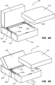
- Figure 4A is a perspective view of the reclining assembly 510 in a compressed position with seat cushion 514 exploded therefrom.
- Figure 4B is a perspective view of the reclining assembly of Figure 4A in an extended, reclined position.
- Figures 4A-B show that the housing 518 of base 512 is configured to be mounted on a support surface, such as a floor and that footrest assembly 513 of base 512 selectively moves outwardly therefrom into an extended position as backrest 520 mounted on base 512 simultaneously reclines to the reclined position.
- Two part couplers such as VELRCO strips 528A-C mounted on the upper face of footrest assembly 513 and the lower face of cushion 514 respectively maintain cushion 514 on footrest assembly 513 as footrest assembly 513 moves to the extended position.
- Figures 4A-B further show passageways 530a-b on opposing sides of base 512 that are defined at the interface of the respective side edges of the footrest assembly 513 and housing 518.
- Couplers such as couplers 15 of Figure 6 are selectively placed in respective passageways 530A-B in order to couple a side of recliner assembly 510 to: (i) a base 12 of modular furniture assembly 10; (ii) another base 512 of a recliner assembly 510; or (iii) a transverse member 14. Examples of these connections are shown in Figures 1A-B and Figure 6 , for example.
- Figure 4C is a perspective view of the base 512 of the reclining assembly 510 with the backrest 520 removed and with the brackets 532 of the reclining mechanism 534 shown in the non-reclined position.
- Figure 4D is a perspective view of the base 512 of Figure 4C with the brackets 532 of the reclining mechanism 534 moved to the reclined position.
- base 512 is comprised of housing 518 and footrest assembly 513, which is moved within housing 518 by reclining mechanism 534.
- Housing 518 of base 512 is comprised of three panels 540A-C, which form a U-shaped framework to which recliner mechanism 534 is affixed.
- the recliner mechanism 534 is also affixed to footrest assembly 513 and selectively moves footrest assembly 513 inwardly and outwardly with respect to housing 518.
- Footrest assembly 513 is comprised of (i) a top panel 542 having rear slits for movement of brackets 532; (ii) a front panel 544a; and (iii) opposing side panels 544b and 544c, wherein the front and side panels 544a-c extend downwardly from top panel 542 to thereby hide the reclining mechanism 534 from view of a user or others viewing the reclining assembly 510.
- the bars and motor of reclining mechanism 534 are generally not visible when viewing reclining assembly 510 - in part because of protective panels 544a-c extending downwardly at a substantially transverse angle from top panel 542. Panels 542, 544a-c may be padded for the user's comfort.
- Four foot support members 546a-b are mounted on the four respective underside corners of housing 518 to maintain base 512 in a stable position on a support surface.
- the fixed (non-moving) framework 538 ( Figs. 7A-b ) of reclining mechanism 534 is mounted within the housing 518, as shown in Figure 4D .
- a reclining motor 536 is coupled at one end of the motor to the fixed framework 538 and at another end of the motor to the moving framework 568 ( Figs 7A-B ) of recliner mechanism 534, which is connected to footrest assembly 513, to thereby selectively move the footrest assembly 513 outwardly and inwardly, simultaneously moving brackets 532 of reclining mechanism 534 backward and forward.
- FIG. 5A is an exploded view of the reclining assembly 510, illustrating placement of the backrest 520 onto the brackets 532 of reclining mechanism 534 of base 512.
- Backrest 520 comprises a cushion assembly 548 and receiving members 560 mounted therein.
- Opposing receiving members 560 housed within the backrest cushion assembly 548 are configured to interlock with respective brackets 532 on opposing sides of base 512 as receiving members 560 are mounted onto brackets 532.
- brackets 532 Upon mounting the receiving members 560 of the backrest 520 onto brackets 532, corresponding connection members within receiving members 560 and on brackets 532 snap or lock into each other, fixing the brackets 532 within backrest 520, such as in a spring loaded, detent, and/or other interlocking arrangement.
- Figure 5B shows the backrest 520 mounted on the brackets 532 of base 512, and further shows the skirt 550 of backrest 520, which extends from backrest cushion assembly 548, being attached to the housing 518 using two part connection members 552, 558, on respective inside of skirt 550 and outside surfaces of housing 518, such as VELCRO, for example.
- Connection members 556 of two-part connection members, such as VELCRO can be mounted on the outer surfaces of skirt 550 in order to selectively connect to an outer cover that may be selectively mounted on backrest 520.
- Skirt 550 thus has connection members on both sides thereof, one set of connection members to attach to housing 518 and another set of connection members to attach to an outer cover (not shown) that is selectively mounted on backrest 520.
- skirt 550 is comprised of a flaccid material that drapes along the back of housing 518 and has hook and/or pile connection members, e.g., VELCRO thereon or other two part connection mechanism, enabling connection of a cover thereto.
- Cushioning assembly 548 may have one or more cushions therein.
- Figure 5C shows the reclining assembly 510 wherein the skirt 550 of the backrest 520 has been attached to the housing 518 of the base 518 with assembly 510 in the compressed, non-extended position.
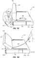
- Figure 5D illustrates the selective movement of the reclining assembly 510 back and forth between the extended, reclined position and the compressed, non-reclined position using a wired controller 560, although integral, wireless and software application driven controllers may optionally be employed.
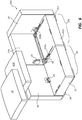
- FIG. 6 The coupling of reclining assembly modular furniture assembly 10 is shown in Figure 6 .
- one or more and preferably two, couplers 15 are selectively mounted within corresponding slits 62 within base member 12 and within the passageway(s) 530A-B of reclining assembly 510.
- a respective portion of each of base 12 and base 512 are coupled between each of the couplers 15, thereby affixing modular furniture assembly 10 to reclining assembly 510.
- Foot couplers 34 also selectively couple reclining member 510 to modular furniture assembly 10.
- Couplers 15 and the foot coupler 34 and/or or other couplers may be selectively removed when one desires to remodel or reconfigure the furniture system 500. Also shown in Figure 6 , couplers 15 selectively couple respective transverse members 14 to base 12 and base 510.
- Figure 6 thus demonstrates the selective connection of the reclining assembly 510 of Figure 1A to the modular furniture assembly 10 of Figure 1A to form the furniture system of Figure 1A , the respective seat cushions being shown in an exploded view.
- Reclining assembly 510 is conveniently coupled to modular furniture assembly 10 through the use of couplers 15, which can be the same U-shaped couplers used to couple transverse member 14 to base member 12 (see Figs. 2A-B ), for example.
- one or more couplers 15 are mounted within the passageway 530a (between housing 518 and footrest assembly 513) of base 512 of reclining assembly 510 and within a corresponding slit 62 of base 512, as shown in Figure 6 .
- a transverse member 14 is similarly coupled to base 512 in a similar fashion, e.g., by mounting a coupler 15 within a passageway 530b of base 512 and within a corresponding cavity of the transverse member 14.
- base 512 has convenient passageways 530a-b on first and second side thereof for convenient connections to base 12, transverse member 14 and/or other bases 512 of reclining assemblies 510.
- One plate of the coupler 15 is placed within a slit of base 12 while the other plate of the coupler 15 is placed within a passageway of base 512, for example.
- Passageways 130a-b between housing 518 and footrest assembly 513 thus enable convenient placement of a coupler such as the coupler 15 in order to selectively couple a modular furniture assembly 10 to a recliner assembly 510.
- the recliner assembly 510 may also be selectively coupled to modular furniture assembly 10 through the use of one or more foot couplers 34 as shown in Figure 1A , coupling a corresponding foot of the recliner assembly 510 to a corresponding foot of a base 12 or transverse member 14 of a modular furniture assembly 10.
- Figure 6A demonstrates the connection of the front end 599 ( Figure 6 ) of the reclining assembly of Figures 1A and 6A to another base 12 through the use of a U coupler 15, and shows the reclining assembly 510 in an extended position.
- Figure 6A it is possible to effectively lengthen the base 512 of the reclining assembly 510 by selectively coupling an additional base 12 to the front 599 of the base 512, e.g., through the use of a U-coupler 15 as shown in Figure 6A .
- the additional base 12 mounted to the front of footrest 513 slides back and forth on the front and/or rear feet thereof, or optionally, can move on rollers or casters or similar devices.
- the front and/or rear feet of the additional base 12 of Fig. 6 have felt or plastic thereon for sliding on a respective surface and/or may be mounted within foot couplers that have felt or plastic thereon for sliding on a respective surface.
- foot couplers 34 are mounted on the front and/or rear feet of the additional base 12. Such foot couplers 34 can assist in coupling the additional base 12 to base 512 and can move when the additional base 512 moves, for example.
- a method for forming the furniture system of Figure 6A thus further comprises placing an additional base 12 adjacent the front 599 of a footrest assembly 513 of the reclining assembly 510 and coupling the additional base 12 to the footrest assembly 513, as illustrated in Fig. 6A , the additional base 12 moving when the base 512 of the reclining assembly moves.
- Figure 6A further shows how coupler 15 remains stationary relative to the base 12 of furniture assembly 10 on the left side of Figure 6A , while coupling said base 12 to base 512 of reclining assembly 510. While coupler 15 remains stationary relative to such base 12 and relative to housing 518 of base 512, there is relative movement by footrest assembly 513 with respect to base 12, housing 518, and coupler 15. Thus the mounting of couplers 15 within respective slots 530a, 530b effectively maintains base 12 coupled to housing 518 while still allowing movement of footrest assembly 513.
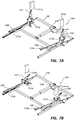
- Figures 7A and 7B show respective perspective views of an example of a recliner mechanism 534 of the present invention, showing the recliner mechanism 534in a compressed, non-reclined position in Figure 7A and an extended, reclined position in Figure 7B .
- Recliner mechanism 534 is comprised of (i) a fixed (non-moving) framework 538 that is affixedly mounted within the housing 518; (ii) a moving framework 568 that is movably coupled to the fixed framework; and (iii) a reclining motor that is coupled to the moving framework 568 and the nonmoving framework 538 and that selectively moves the moving framework 568 with respect to the non-moving framework 538.
- the moving framework includes brackets 532 which couple to the backrest 520.
- the nonmoving framework mounted within housing 518 is comprised of a rail assembly upon which a portion of the moving framework moves, e.g., through rolling or sliding, wherein the extension motor 536 selectively moves the moving framework along the rail assembly.
- the moving framework 568 includes a pair of rail members that moves outwardly when the moving framework 568 is pressed by the extension motor 536. Upon such movement, upright bracket members 532 each pivot backwards, reclining the backrest member 520. Thus, the reclining mechanism 534, selectively slides footrest assembly 513 back and forth with respect to housing 518 and simultaneously reclines and inclines backrest 520.
- Front attachment members 570a-b of the moving framework 568 attach to the upper panel 542 of base 512, while rear attachment members 572a-b attach to the upper panel 542 through the use of respective extension blocks 574a-b mounted between members 572a-b and panel 548.
- assembly 534 is conveniently hidden or at least substantially hidden in use behind panels 544a-c.
- an advantage of one embodiment of reclining assembly 510, as shown in the Figure 1B , 3B , 4B , and 5B is that moveable footrest assembly 513 extends outwardly from housing 518 in a manner that the reclining mechanism 534 is not seen or is substantially not seen from the sides or from the front of assembly 510.
- the outwardly moving footrest assembly 513 appears in the extended positon as a natural piece of furniture, as if it had not been reclined, as opposed to a mechanized plate that is common in typical recliners.
- This extended footrest assembly 513 is more aesthetically pleasing than the view of the footrest of a typical mechanized recliner, which often does not hide the reclining mechanism.
- the furniture system 10 when recliner assembly 510 is in the compressed position, the furniture system 10 appears similar to a typical non-recliner couch or sofa system. However, when moved to the extended, reclined position of Figures 1B , the system 10 is conveniently comfortable for a reclining individual.
- Recliner mechanism 534 may be a variety of different commercially available reclining mechanisms, such as reclining mechanisms available from Leggett and Platt, 1 Leggett Road, Carthage, Mo, 64836, U.S.A., (website: homefurniturecomponents.com), such as reclining mechanisms available in INSPIRA branded furniture or other wall-hugging reclining mechanisms from Leggett and Platt, 1 Leggett Road, Carthage, Mo, 64836, U.S.A., for example, or a variety of other commercially available recliner mechanisms, for example.
- Figure 8 demonstrates an example of a hand-held controller assembly 580 of the present invention.
- the reclining of the reclining assembly 510 is controlled by a hand-held controller assembly 580 controlled by touch control buttons 582a-b, the controller assembly 580 being electrically linked by an electrical cord (or wirelessly) to the motor 536 of the reclining mechanism 534.
- Figures 9A-B demonstrate an alternate example of an alternate reclining controller assembly in the form of a touch control controller assembly mounted on a seat cushion.
- the reclining control assembly of Figures 9A-9B comprises outer cover buttons 586a-b; corresponding inner cover buttons 588a-b; and corresponding outer cushion insert buttons 592a-b, which connect to each other as illustrated and which are electrically coupled to the reclining mechanism of reclining assembly 510a.
- the reclining control assembly comprises touch control buttons 586a-b mounted on the side of the seat cushion 514 of reclining assembly 510a, the control buttons 586a-b being electrically linked by an electrical cord (or optionally, wirelessly) to the motor 536 of the reclining mechanism 534.
- buttons 586a-b which may be inductive touch control buttons, for example, use impulses received from the touch of a user's finger to control the amount of reclining performed by reclining mechanism 534. Using the touch control buttons 586a-b, the user can selectively recline and incline the reclining assembly 510a.
- Cushion 514 is comprised of an outer cover 515a and an inner cushion insert 514b.
- Outer cushion cover 515a is selectively mounted on inner cushion insert 514b.
- Inner cushion insert 515b comprises, in one embodiment, a cushioning (e.g., foam) material covered by a thin insert cover.
- Outer cover buttons 586a-b may attach to respective inner cover buttons 588a-b in a variety of different manners, such as mechanically, magnetically, friction fit, adhesives, integral connection, or a variety of different attachment methods.
- the prongs of inner cover buttons 588a-b are moved into the grooves of respective outer cover buttons 586a-b and bent within the spaces defined by the grooves of respective outer cover buttons 586a-b (e.g., within the cavity inside the dome -shaped cover buttons 586a-b) to thereby affix respective buttons inner and outer cover buttons to each other with the cover therebetween.
- buttons 586a-b are coupled on the outside of the outer cover 515a of cushion 514 for contact by a user. Buttons 586a-b attach via attachment members extending through the fabric of the outer cover 515a to corresponding inner cover buttons 588a-b, as shown in Figures 9A-9B .
- buttons 588a-b are in physical and magnetic contact with corresponding cushion insert outer buttons 590a-b. Buttons 588a-b thus magnetically connect to corresponding buttons 590a-b.
- Cushion insert outer buttons 588a-b are on the outside of cushion insert 515b electrically coupled to wires 592a-b which electrically couple via wiring bundle 594 to a corresponding wiring connection 596 on the base 512a of the reclining assembly 510a, which is electrically linked to the motor 536 of the reclining mechanism 534.
- the inner cover buttons 588a-b are in physical and magnetic contact with corresponding cushion insert outer buttons 590a-b such that outer cover buttons 586a-b can be touched by the user to control the reclining of the reclining assembly 510a.
- the outer cover 515a having outer touch buttons 586a-b and corresponding inner buttons 588a-b can be selectively, magneticaly mounted onto cushion insert 515b and can be selectively removed from cushion insert 515b.
- removable outer cover 515a can be removed from insert 515b and washed independently and/or replaced with a new outer cover 515a having the same configuration and buttons with a different color or fabric, etc.
- Buttons 586a-b and attached buttons 588a-b of removable cover 515a electrically couple to outer buttons 590a-b of insert 515b when cover 515a is selectively mounted thereon.
- Washable, removable outer cover 515a is thus selectively mounted on insert 515b and has touch control buttons 586a-b mounted thereon for convenient reclining of recliner assembly 510a.
- recliner assembly 510a can be configured with the same elements, configurations, and specifications as the recliner assembly 510 of Figures 1-7 , plus the additions of the control buttons of Figures 9A-B .
Landscapes
- Health & Medical Sciences (AREA)
- General Health & Medical Sciences (AREA)
- Dentistry (AREA)
- Nursing (AREA)
- Chairs For Special Purposes, Such As Reclining Chairs (AREA)
Description
- This invention is in the field of furniture systems with recliners.
- Modular furniture is advantageous in part because it enables a variety of different furniture configurations to be created using a limited number of parts and because in manufacturing and design, only a limited number of designs are needed, simplifying the manufacturing and supply process. Modular furniture is therefore both efficient, convenient and valuable. It is also important that modular furniture be comfortable so that users will want to sit and remain seated in a sofa configuration, for example, or in a chair or other furniture system.
- Traditional furniture has evolved into a variety of different furniture configurations that enable the user to sit comfortably in a variety of different seated positions. For example, traditional furniture features extensive numbers of pieces in order to create a large couch, or a sectional seating configuration in which a number of people can enjoy sitting together to engage in an activity or to watch television or a movie together as a group or family, for example. Recliners, for example, can be used to move from a sitting position to a reclining position in order to further relax the muscles of the back. Typical recliners, however, often have a bulky, mechanized appearance that is not aesthetically pleasing or contiguous with the appearance of neighboring furniture pieces. It is often possible to tell which piece is a recliner, often yielding an unpleasant and non-unified appearance.
- Furthermore, many traditional recliners included in sectional couches cannot be positioned closely against a wall because the backrest of the recliner section will often need space behind it in order to recline. This requires the placement of the entire sectional couch system to be sufficiently far away from a wall to allow for the recliner section to recline. This may reduce the usable space within a room and or leave undesired spaces between the furniture and the wall.
-
US2005/0253430A1 discloses a seating system including several seating units that are coupled together with at least one bracket, where the bracket extends between two seating units.JPH09-173176A - What is needed is modular furniture system that also has some of the advantages and comforts of large traditional seating systems so that a user of modular furniture can also enjoy the benefits of a large seating system.
- According to a first aspect of the invention there is provided a furniture system as claimed in claim 1, comprising: (A) a modular furniture assembly comprising a base and a transverse member that can be selectively coupled to each other; and (B) a reclining assembly configured to be selectively coupled to the modular furniture assembly, wherein the reclining assembly is configured to be mounted adjacent to the modular furniture assembly such that the reclining assembly can be selectively coupled to the modular furniture assembly to form a sofa, wherein the reclining assembly comprises: (1) a base configured to be mounted on a support surface, the base comprising: (i) a housing; and (ii) a footrest assembly that moves with respect to the housing, and wherein a passageway extends between the housing and the footrest assembly such that a coupler is selectively mounted within the passageway and within a corresponding slit of the modular furniture assembly to thereby couple the reclining assembly to the modular furniture assembly.
- According to a second aspect of the invention there is provided a furniture system as claimed in claim 8, comprising: (A) a modular furniture assembly having footprint specifications which identify the footprint of the modular furniture assembly, the modular furniture assembly comprising a base and a transverse member that can be selectively coupled to each other; and (B) a reclining assembly configured to be selectively coupled to the modular furniture assembly, wherein the reclining assembly is configured to be mounted adjacent to the modular furniture assembly such that the reclining assembly can be selectively coupled to the modular furniture assembly to form a convenient, useful, and aesthetically pleasing sofa, wherein, in a compressed, non-reclined position, the reclining assembly has substantially the same footprint specifications as the footprint specifications of the modular furniture assembly, and further comprising an additional base mounted on a front of a base of the reclining assembly, the additional base moving when the base of the reclining assembly moves.
- These and other objects and features of the present invention will become more fully apparent from the following description and appended claims, or may be learned by the practice of the invention as set forth hereinafter.
- To further clarify the above and other advantages and features of the present invention, a more particular description of the invention will be rendered by reference to specific embodiments thereof which are illustrated in the appended drawings. It is appreciated that these drawings depict only illustrated embodiments of the invention and are therefore not to be considered limiting of its scope. The invention will be described and explained with additional specificity and detail through the use of the accompanying drawings in which:
-
Figure 1A is a perspective view of afurniture system 500 of the present invention in the form of a sofa with a recliningassembly 510 shown in a compressed (non-reclined) position and having an appearance similar to the adjacentmodular furniture assembly 10, which is selectively coupled to the recliningassembly 510. -
Figure 1B is a perspective view of the furniture system ofFigure 1A with the reclining assembly shown in an extended, reclined position. -
Figure 2A is a perspective view of the modular furniture assembly ofFigure 1 . -
Figure 2B is an exploded view of the modular furniture ofFigure 1 and2A . -
Figure 3A is a perspective view of the reclining assembly ofFigure 1 in a compressed position with a back cushion exploded therefrom. -
Figure 3B is a perspective view of the reclining assembly ofFigures 1 and3A in an extended, reclined position. -
Figure 4A is a perspective view of the reclining assembly ofFigures 1 and4A in a compressed position with a seat cushion exploded therefrom. -
Figure 4B is a perspective view of the reclining assembly ofFigure 4A in an extended, reclined position. -
Figure 4C is a perspective view of the base of the reclining assembly ofFigure 4A with the backrest removed and with the brackets of the reclining mechanism in the compressed, non-reclined position. -
Figure 4D is a perspective view of the base ofFigure 4C with the brackets of the reclining mechanism moved to the extended, reclined position. -
Figure 5A is an exploded view of the reclining assembly of the present invention, illustrating placement of the backrest onto the reclining mechanism of the base. -
Figure 5B is a perspective view of the reclining assembly ofFigure 5A , wherein the backrest has been mounted on the reclining mechanism of the base and the skirt of the backrest is being attached to the housing of the framework of the base. -
Figure 5C is a perspective view the reclining assembly ofFigures 5A and 5B wherein the skirt of the backrest has been attached to the housing of the framework of the base. The reclining assembly is in the compressed, non-extended position. -
Figure 5D is a perspective view of the reclining assembly ofFigures 5A-5C , wherein the reclining assembly is in the extended, reclined position. -
Figure 6 demonstrates the connection of the reclining assembly ofFigure 1A to the modular furniture assembly ofFigure 1A to form the furniture system ofFigure 1A . -
Figure 6A demonstrates the reclining assembly ofFigure 6 in a reclined position and further shows the connection of abase 12 to the reclining assembly ofFigures 1A and6A through the use of a U coupler. -
Figures 7A and 7B show respective perspective views of an example of a recliner mechanism of the present invention, showing the recliner mechanism in a compressed, non-reclined position inFigure 7A and an extended, reclined position inFigure 7B . -
Figure 8 demonstrates an example of a hand-held controller assembly of the present invention having a wired connection to the motor of the reclining mechanism. -
Figures 9A-B demonstrate an example of an alternative reclining controller in the form of a touch control controller assembly comprising touch control buttons mounted on a seat cushion of the reclining assembly . -
Figure 1A is a perspective view of afurniture system 500 of the present invention with a recliningassembly 510 shown in a compressed (non-reclined) position.Figure 1B is a perspective view of the furniture system ofFigure 1A with the recliningassembly 510 shown in an extended, reclined position. - As shown in
Figures 1A-1B , thefurniture system 500 is a sofa comprised of: (i) amodular furniture assembly 10; and (ii) a recliningassembly 510 positioned adjacent themodular furniture assembly 10 and selectively coupled thereto in a unified, aesthetically pleasing manner such that the recliningassembly 510 generally has the appearance of another modular furniture assembly, rather than a bulky, awkward meachanized recliner. - The
modular furniture assembly 10 ofFigures 1A-1B andFigures 2A-2B is comprised of: (i) abase member 12 for sitting on by a user; and (ii) atransverse member 14 configured to be used as a backrest and/or an arm rest. Such modular furniture assemblies are highly advantageous, particularly those having a ratio of x=x'=y+z wherein x is the length of the base, x' is the length of the transverse member and wherein y equals the width of the base and z equals the width of the transverse member. This x=x'=y+z relationship enables a variety of different furniture configurations to be formed, using only the design of the base and the design of the transverse member. -
Base member 12 is selectively coupled totransverse member 14 and interacts withtransverse member 14 as described in (i)U.S. Patent Application Serial No. 14/332,705, filed July 16, 2014 U.S. Patent No. 8,783,778 , entitled MOUNTING PLATFORM FOR MODULAR FURNITURE ASSEMBLY, (iii)U.S. Patent No. 7,963,612 entitled MODULAR FURNITURE ASSEMBLY, (iv)U.S. Patent Application Serial No. 11/449,074, filed June 8, 2006 U.S. Patent No.7,547,073 , (v)U.S. Patent No. 7,213,885 entitled MODULAR FURNITURE ASSEMBLY, (vi)U.S. Provisional Application No. 62/354,426 filed June 24, 2016 U.S. Provisional Patent Application Serial Number 62/257,623, filed on November 19, 201515/270,339, filed on September 20, 2016 15/276,524 - As shown in
Figures 1A-2B ,modular furniture assembly 10 is comprised of abase member 12, one or moretransverse members 14, aseat cushioning member 18 mounted onbase member 12 and aback cushioning member 20 mounted adjacent atransverse member 14.Transverse member 14 is selectively coupled tobase member 12 bycoupler 15 and one ormore foot couplers 34.Other couplers 15 andfoot couplers 34 can be used to connect additionaltransverse members 14 to one ormore bases 12, e.g., as backrests or armrests as shown inFigure 1B , which also shows atransverse member 14 coupled to recliningassembly 510 as an armrest. - In the embodiment of
Figures 2A and 2B as discussed in United States Patent No.7,213,885 , the length x ofbase 12 is substantially equal to the length x' of transverse member, each of which are substantially equal to the width y of base plus the width z of transverse member, such that x=x'=y+z. This dynamic of x=x'=y+z enables a variety of different furniture configurations to be formed and is an efficient configuration for a furniture system. -
Seat cushion 18 can be selectively attached tobase 12, e.g., through the use of a two-part attachment member such as VELCRO. - Also as shown in
Figures 1A-1B and as further shown inFigures 3A-B , recliningassembly 510 is comprised of abase 512 configured to be mounted on a support surface.Base 512 includes afootrest assembly 513 and aseat cushion 514 is mounted on thefootrest assembly 513, upon which aback cushion 516 is mounted. Abackrest 520 is mounted on thebase 512, as discussed further in additional detail below. - The reclining
assembly 510 is configured to have a footprint that substantially fits within the mathematical specifications of the footprint of themodular furniture assembly 10 and has a similar overall aesthetically appearance. Thus, as shown inFigure 1A , recliningassembly 510 appears to be anothermodular furniture assembly 10 and does not have bulky, awkward looking mechanized parts shown to a consumer or user. As shown inFigure 1A , the recliningassembly 510 has the general appearance that is similar to themodular furniture assembly 10 when the recliningassembly 510 is in the un-reclined position. In the compressed, non-reclined position, recliningassembly 510 uses approximately the same amount of footprint as the amount of footprint used bymodular furniture assembly 10. - Thus, as shown in
Figure 1A , the combination of themodular furniture assembly 10 and thereclining assembly 510 generates a unified, aesthetically pleasing looking couch, which looks like two modular furniture assemblies mounted next to each other, rather than appearing to have an awkward bulky, mechanized recliner mounted next to a modular furniture assembly. Thus, as shown inFigure 1A , a coherent, unified couch design and configuration can be created when thereclining assembly 510 is mounted adjacent amodular furniture assembly 10 of thefurniture system 500. -
Figure 3A is a perspective view ofreclining assembly 510 in a compressed position with theback cushion 516 exploded therefrom.Figure 3B is a perspective view of thereclining assembly 510 in an extended, reclined position. As shown in these figures, thebase 512 of recliner assembly is comprised of afootrest assembly 513 and ahousing 518, wherein thefootrest assembly 513 selectively moves outwardly with respect tohousing 518, creating a comfortable footrest for a user, e.g., through the use of a wired remote controller, a wireless remote controller, buttons on a portion of theassembly 510, and/or a software application on a mobile device (e.g., a cellular phone), for example.Seat cushion 514 is mounted on thefootrest assembly 513 portion ofbase 513, e.g. through the use of two part coupler, such as VELCRO, for example, and moves outwardly withfootrest assembly 513 asfootrest assembly 513 is moved to the extended position ofFigure 3B . - As shown in
Figures 3A , in the non-reclined compact position,base 512 is comprised of: (i) a two-piece framework having a length x" and a width x'" wherein the framework is a rectangular framework and wherein x"=x'''. The framework ofbase 512 comprises: (A) ahousing 518, which rests on the floor; and (B)movable footrest assembly 513 which moves with respect tohousing 518.Base 512 further comprises a recliner mechanism 534 (Figs. 7A-B ) mounted within thehousing 518 and coupled to thefootrest assembly 513, therecliner mechanism 534 selectively moving thefootrest assembly 513 with respect to thehousing 518. Thebackrest 520 is coupled to the recliner mechanism 534 (Figs. 7A-B ) of thebase 512. The recliner framework remains within the x"=x''' footprint in the compressed position ofFig. 3A and at least a portion of thefootrest assembly 513 moves out of the x"=x''' footprint in the extended position (Fig. 3B ). -
Backrest 520 ofrecliner assembly 510 is mounted on thebrackets 532 of reclining mechanism 534 (Figs 7A-B ), thefree end 522 ofbackrest 520 selectively reclining or inclining as illustrated inFig. 3B whenassembly 510 is moved to the extended, reclined position and back to the non-reclined position. - The
reclining assembly 510 ofFigures 1A-1B andFigures 3A-3B enables reclining in a system that employs a footprint having a ratio similar to the x=x'=y+z ratio. As reflected inFigures 1A and3A , in the compressed position,base 512 has an overall footprint whereinbase 512 has a length of x" which is substantially equal to the width x''' ofbase 512. As a result, in the reclining assembly, the length x" and the width x''' are substantially equal to each other and are also substantially equal to the length x ofbase member 12 which is substantially equal to the length x' oftransverse member 14, each of which are substantially equal to the width y of thebase member 12 plus the width z of thetransverse member 14. Thus x=x'=x"=x'''=y+z. As a result, the mathematical specifications of the footprint used by themodular furniture assembly 10 ofFigure 2A are the same or substantially the same as the mathematical specifications of the footprint used by recliningassembly 510 ofFigure 3A . - As a result, in the embodiment of
Figure 1A , thereclining assembly 510 sits adjacent themodular furniture assembly 10 and appears to be another modular furniture assembly adjacent thereto, rather than a bulky mechanized recliner. In fact, however, therecliner assembly 510 selectively reclines with respect tomodular furniture assembly 10. - The
reclining assembly 510 is thus advantageous in part because it fits aesthetically and pleasingly adjacentmodular furniture assembly 10 which has a configuration of x=x'=y+z and in part because it uses the same or similar amount of footprint used bymodular furniture assembly 10. As a result, it fits in an aesthetically pleasing manner withinsystem 500 and is both functionally efficient and pleasing to the eye. - As shown in
Figure 3B ,housing 518 ofrecliner assembly 510 rests on the floor whilemoveable footrest assembly 513 moves outwardly with respect tohousing 518 andfree end 522 ofbackrest 520 simulating moves downwardly towardshousing 518. Thusfootrest assembly 513 andbackrest 520 selectively move simultaneously,footrest assembly 513 moving back and forth whilebackrest 520 moves up and down. - In one embodiment, the backrest of the present invention can be configured to transition between the compressed, non-reclining position to the extended, reclined position without moving the free end of the backrest backwards or substantially backwards toward a wall adjacent to which the recliner is placed; in this embodiment, the lower portion of the backrest moves sufficiently forward during reclining that the free end of the backrest does not move substantially backward toward the wall as the recliner reclines. This can allow the reclining assembly, and therefore any other assemblies adjacent to the reclining assembly, to be placed with the backrest in contact, or nearly in contact with, a wall. The reclining mechanism may be a wall-hugging mechanism, for example. This allow users to place associated modular furniture systems directly next to a wall, saving floor space within a room and avoiding unnecessary space between the furniture and the wall. Thus, in one embodiment, the recliner assembly of the present invention can be situated with the backrest in contact or nearly in contact with a wall when the reclining assembly is in a compressed, non-reclined position and the free end of the backrest does extend substantially backwards towards the wall as the recliner assembly is moved to an extended, reclined position.
-
Figure 4A is a perspective view of thereclining assembly 510 in a compressed position withseat cushion 514 exploded therefrom.Figure 4B is a perspective view of the reclining assembly ofFigure 4A in an extended, reclined position. -
Figures 4A-B show that thehousing 518 ofbase 512 is configured to be mounted on a support surface, such as a floor and thatfootrest assembly 513 ofbase 512 selectively moves outwardly therefrom into an extended position asbackrest 520 mounted onbase 512 simultaneously reclines to the reclined position. Two part couplers such as VELRCO strips 528A-C mounted on the upper face offootrest assembly 513 and the lower face ofcushion 514 respectively maintaincushion 514 onfootrest assembly 513 asfootrest assembly 513 moves to the extended position. -
Figures 4A-B further showpassageways 530a-b on opposing sides ofbase 512 that are defined at the interface of the respective side edges of thefootrest assembly 513 andhousing 518. Couplers, such ascouplers 15 ofFigure 6 are selectively placed in respective passageways 530A-B in order to couple a side ofrecliner assembly 510 to: (i) abase 12 ofmodular furniture assembly 10; (ii) anotherbase 512 of arecliner assembly 510; or (iii) atransverse member 14. Examples of these connections are shown inFigures 1A-B andFigure 6 , for example. -
Figure 4C is a perspective view of thebase 512 of thereclining assembly 510 with thebackrest 520 removed and with thebrackets 532 of thereclining mechanism 534 shown in the non-reclined position.Figure 4D is a perspective view of thebase 512 ofFigure 4C with thebrackets 532 of thereclining mechanism 534 moved to the reclined position. - With reference to
Figures 4C-D ,base 512 is comprised ofhousing 518 andfootrest assembly 513, which is moved withinhousing 518 by recliningmechanism 534. -
Housing 518 ofbase 512 is comprised of three panels 540A-C, which form a U-shaped framework to whichrecliner mechanism 534 is affixed. Therecliner mechanism 534 is also affixed tofootrest assembly 513 and selectively movesfootrest assembly 513 inwardly and outwardly with respect tohousing 518. -
Footrest assembly 513 is comprised of (i) atop panel 542 having rear slits for movement ofbrackets 532; (ii) afront panel 544a; and (iii) opposingside panels side panels 544a-c extend downwardly fromtop panel 542 to thereby hide thereclining mechanism 534 from view of a user or others viewing thereclining assembly 510. For example, as shown inFigures 1A-1B , the bars and motor ofreclining mechanism 534 are generally not visible when viewing reclining assembly 510 - in part because ofprotective panels 544a-c extending downwardly at a substantially transverse angle fromtop panel 542.Panels -
Side panels 544b-c slide outside of respectiveindented panels 547a-b extending fromrespective panels 540b-c ofhousing 518. - Four
foot support members 546a-b are mounted on the four respective underside corners ofhousing 518 to maintain base 512 in a stable position on a support surface. - The fixed (non-moving) framework 538 (
Figs. 7A-b ) ofreclining mechanism 534 is mounted within thehousing 518, as shown inFigure 4D . Areclining motor 536 is coupled at one end of the motor to the fixedframework 538 and at another end of the motor to the moving framework 568 (Figs 7A-B ) ofrecliner mechanism 534, which is connected tofootrest assembly 513, to thereby selectively move thefootrest assembly 513 outwardly and inwardly, simultaneously movingbrackets 532 ofreclining mechanism 534 backward and forward. -
Figure 5A is an exploded view of thereclining assembly 510, illustrating placement of thebackrest 520 onto thebrackets 532 ofreclining mechanism 534 ofbase 512.Backrest 520 comprises acushion assembly 548 and receivingmembers 560 mounted therein. Opposing receivingmembers 560 housed within thebackrest cushion assembly 548 are configured to interlock withrespective brackets 532 on opposing sides ofbase 512 as receivingmembers 560 are mounted ontobrackets 532. - Upon mounting the receiving
members 560 of thebackrest 520 ontobrackets 532, corresponding connection members within receivingmembers 560 and onbrackets 532 snap or lock into each other, fixing thebrackets 532 withinbackrest 520, such as in a spring loaded, detent, and/or other interlocking arrangement. -
Figure 5B shows thebackrest 520 mounted on thebrackets 532 ofbase 512, and further shows theskirt 550 ofbackrest 520, which extends frombackrest cushion assembly 548, being attached to thehousing 518 using twopart connection members skirt 550 and outside surfaces ofhousing 518, such as VELCRO, for example.Connection members 556 of two-part connection members, such as VELCRO can be mounted on the outer surfaces ofskirt 550 in order to selectively connect to an outer cover that may be selectively mounted onbackrest 520.Skirt 550 thus has connection members on both sides thereof, one set of connection members to attach tohousing 518 and another set of connection members to attach to an outer cover (not shown) that is selectively mounted onbackrest 520. - In one embodiment,
skirt 550 is comprised of a flaccid material that drapes along the back ofhousing 518 and has hook and/or pile connection members, e.g., VELCRO thereon or other two part connection mechanism, enabling connection of a cover thereto. Cushioningassembly 548 may have one or more cushions therein. -
Figure 5C shows thereclining assembly 510 wherein theskirt 550 of thebackrest 520 has been attached to thehousing 518 of the base 518 withassembly 510 in the compressed, non-extended position. -
Figure 5D illustrates the selective movement of thereclining assembly 510 back and forth between the extended, reclined position and the compressed, non-reclined position using awired controller 560, although integral, wireless and software application driven controllers may optionally be employed. - The coupling of reclining assembly
modular furniture assembly 10 is shown inFigure 6 . As shown in this figure, one or more and preferably two,couplers 15 are selectively mounted within correspondingslits 62 withinbase member 12 and within the passageway(s) 530A-B of recliningassembly 510. A respective portion of each ofbase 12 andbase 512 are coupled between each of thecouplers 15, thereby affixingmodular furniture assembly 10 to recliningassembly 510.Foot couplers 34 also selectively couple recliningmember 510 tomodular furniture assembly 10. -
Couplers 15 and thefoot coupler 34 and/or or other couplers, may be selectively removed when one desires to remodel or reconfigure thefurniture system 500. Also shown inFigure 6 ,couplers 15 selectively couple respectivetransverse members 14 tobase 12 andbase 510. -
Figure 6 thus demonstrates the selective connection of thereclining assembly 510 ofFigure 1A to themodular furniture assembly 10 ofFigure 1A to form the furniture system ofFigure 1A , the respective seat cushions being shown in an exploded view. - Reclining
assembly 510 is conveniently coupled tomodular furniture assembly 10 through the use ofcouplers 15, which can be the same U-shaped couplers used to coupletransverse member 14 to base member 12 (seeFigs. 2A-B ), for example. - In order to achieve this convenient coupling, one or
more couplers 15 are mounted within thepassageway 530a (betweenhousing 518 and footrest assembly 513) ofbase 512 of recliningassembly 510 and within acorresponding slit 62 ofbase 512, as shown inFigure 6 . Atransverse member 14 is similarly coupled tobase 512 in a similar fashion, e.g., by mounting acoupler 15 within apassageway 530b ofbase 512 and within a corresponding cavity of thetransverse member 14. - Thus
base 512 hasconvenient passageways 530a-b on first and second side thereof for convenient connections tobase 12,transverse member 14 and/orother bases 512 ofreclining assemblies 510. One plate of thecoupler 15 is placed within a slit ofbase 12 while the other plate of thecoupler 15 is placed within a passageway ofbase 512, for example. Passageways 130a-b betweenhousing 518 andfootrest assembly 513 thus enable convenient placement of a coupler such as thecoupler 15 in order to selectively couple amodular furniture assembly 10 to arecliner assembly 510. - The
recliner assembly 510 may also be selectively coupled tomodular furniture assembly 10 through the use of one ormore foot couplers 34 as shown inFigure 1A , coupling a corresponding foot of therecliner assembly 510 to a corresponding foot of a base 12 ortransverse member 14 of amodular furniture assembly 10. -
Figure 6A demonstrates the connection of the front end 599 (Figure 6 ) of the reclining assembly ofFigures 1A and6A to another base 12 through the use of aU coupler 15, and shows thereclining assembly 510 in an extended position. As shown inFigure 6A , it is possible to effectively lengthen thebase 512 of thereclining assembly 510 by selectively coupling anadditional base 12 to thefront 599 of thebase 512, e.g., through the use of a U-coupler 15 as shown inFigure 6A . - In the embodiment of
Figure 6A , when thefootrest assembly 513 ofbase 512 is moved outwardly to the extended position, it pushes theadditional base 12 mounted on thefront 599 thereof. Similarly, when thefootrest assembly 513 ofbase 512 is retracted back to the retracted postion, theadditional base 12 moves to the retracted position with thebase 512. Thus, theadditional base 12 ofFig. 6A effectively lengthens thebase 512 of recliningassembly 510 and theadditional base 12 ofFigure 6A moves back and forth withbase 512 asbase 512 moves between the reclined and non-reclined positions. - In one embodiment, the
additional base 12 mounted to the front offootrest 513 slides back and forth on the front and/or rear feet thereof, or optionally, can move on rollers or casters or similar devices. In one embodiment, the front and/or rear feet of theadditional base 12 ofFig. 6 have felt or plastic thereon for sliding on a respective surface and/or may be mounted within foot couplers that have felt or plastic thereon for sliding on a respective surface. In one embodiment,foot couplers 34 are mounted on the front and/or rear feet of theadditional base 12.Such foot couplers 34 can assist in coupling theadditional base 12 tobase 512 and can move when theadditional base 512 moves, for example. - A method for forming the furniture system of
Figure 6A thus further comprises placing anadditional base 12 adjacent thefront 599 of afootrest assembly 513 of thereclining assembly 510 and coupling theadditional base 12 to thefootrest assembly 513, as illustrated inFig. 6A , theadditional base 12 moving when thebase 512 of the reclining assembly moves. -
Figure 6A further shows howcoupler 15 remains stationary relative to thebase 12 offurniture assembly 10 on the left side ofFigure 6A , while coupling saidbase 12 tobase 512 of recliningassembly 510. Whilecoupler 15 remains stationary relative tosuch base 12 and relative tohousing 518 ofbase 512, there is relative movement byfootrest assembly 513 with respect tobase 12,housing 518, andcoupler 15. Thus the mounting ofcouplers 15 withinrespective slots base 12 coupled tohousing 518 while still allowing movement offootrest assembly 513. -
Figures 7A and 7B show respective perspective views of an example of arecliner mechanism 534 of the present invention, showing the recliner mechanism 534in a compressed, non-reclined position inFigure 7A and an extended, reclined position inFigure 7B . -
Recliner mechanism 534 is comprised of (i) a fixed (non-moving)framework 538 that is affixedly mounted within thehousing 518; (ii) a movingframework 568 that is movably coupled to the fixed framework; and (iii) a reclining motor that is coupled to the movingframework 568 and thenonmoving framework 538 and that selectively moves the movingframework 568 with respect to thenon-moving framework 538. The moving framework includesbrackets 532 which couple to thebackrest 520. - The nonmoving framework mounted within
housing 518 is comprised of a rail assembly upon which a portion of the moving framework moves, e.g., through rolling or sliding, wherein theextension motor 536 selectively moves the moving framework along the rail assembly. - The moving
framework 568 includes a pair of rail members that moves outwardly when the movingframework 568 is pressed by theextension motor 536. Upon such movement,upright bracket members 532 each pivot backwards, reclining thebackrest member 520. Thus, thereclining mechanism 534, selectively slidesfootrest assembly 513 back and forth with respect tohousing 518 and simultaneously reclines and inclinesbackrest 520. -
Front attachment members 570a-b of the movingframework 568 attach to theupper panel 542 ofbase 512, whilerear attachment members 572a-b attach to theupper panel 542 through the use ofrespective extension blocks 574a-b mounted betweenmembers 572a-b andpanel 548. - In one embodiment,
assembly 534 is conveniently hidden or at least substantially hidden in use behindpanels 544a-c. Thus, an advantage of one embodiment of recliningassembly 510, as shown in theFigure 1B ,3B ,4B , and5B is thatmoveable footrest assembly 513 extends outwardly fromhousing 518 in a manner that thereclining mechanism 534 is not seen or is substantially not seen from the sides or from the front ofassembly 510. Thus, the outwardly movingfootrest assembly 513 appears in the extended positon as a natural piece of furniture, as if it had not been reclined, as opposed to a mechanized plate that is common in typical recliners. Thisextended footrest assembly 513 is more aesthetically pleasing than the view of the footrest of a typical mechanized recliner, which often does not hide the reclining mechanism. - Furthermore, the
recliner mechanism 534 is oriented withinhousing 518 so as to selectively move thefootrest assembly 513 respect tohousing 518 and to movebackrest 520 wherein theentire assembly 510 remains within the x"= x''' footprint in the compressed non-extended position while at least a portion of the footrest assembly is configured to move outside of the x"= x'" footprint in the extended, reclined position. - Thus, as shown in
Fig. 1A , whenrecliner assembly 510 is in the compressed position, thefurniture system 10 appears similar to a typical non-recliner couch or sofa system. However, when moved to the extended, reclined position ofFigures 1B , thesystem 10 is conveniently comfortable for a reclining individual. -
Recliner mechanism 534 may be a variety of different commercially available reclining mechanisms, such as reclining mechanisms available from Leggett and Platt, 1 Leggett Road, Carthage, Mo, 64836, U.S.A., (website: homefurniturecomponents.com), such as reclining mechanisms available in INSPIRA branded furniture or other wall-hugging reclining mechanisms from Leggett and Platt, 1 Leggett Road, Carthage, Mo, 64836, U.S.A., for example, or a variety of other commercially available recliner mechanisms, for example. -
Figure 8 demonstrates an example of a hand-heldcontroller assembly 580 of the present invention. In one embodiment as shown inFigure 8 , the reclining of thereclining assembly 510 is controlled by a hand-heldcontroller assembly 580 controlled bytouch control buttons 582a-b, thecontroller assembly 580 being electrically linked by an electrical cord (or wirelessly) to themotor 536 of thereclining mechanism 534. -
Figures 9A-B demonstrate an alternate example of an alternate reclining controller assembly in the form of a touch control controller assembly mounted on a seat cushion. The reclining control assembly ofFigures 9A-9B comprisesouter cover buttons 586a-b; correspondinginner cover buttons 588a-b; and corresponding outercushion insert buttons 592a-b, which connect to each other as illustrated and which are electrically coupled to the reclining mechanism ofreclining assembly 510a. - The reclining control assembly comprises
touch control buttons 586a-b mounted on the side of theseat cushion 514 ofreclining assembly 510a, thecontrol buttons 586a-b being electrically linked by an electrical cord (or optionally, wirelessly) to themotor 536 of thereclining mechanism 534. - One button, e.g.,
button 586a, reclines thereclining assembly 510a while the other button, e.g.,button 586b, returns thereclining assembly 510a to the non-reclined position.Touch control buttons 586a-b, which may be inductive touch control buttons, for example, use impulses received from the touch of a user's finger to control the amount of reclining performed by recliningmechanism 534. Using thetouch control buttons 586a-b, the user can selectively recline and incline thereclining assembly 510a. -
Cushion 514 is comprised of anouter cover 515a and an inner cushion insert 514b.Outer cushion cover 515a is selectively mounted on inner cushion insert 514b.Inner cushion insert 515b comprises, in one embodiment, a cushioning (e.g., foam) material covered by a thin insert cover. -
Outer cover buttons 586a-b may attach to respectiveinner cover buttons 588a-b in a variety of different manners, such as mechanically, magnetically, friction fit, adhesives, integral connection, or a variety of different attachment methods. In one embodiment, for example, the prongs ofinner cover buttons 588a-b are moved into the grooves of respectiveouter cover buttons 586a-b and bent within the spaces defined by the grooves of respectiveouter cover buttons 586a-b (e.g., within the cavity inside the dome -shapedcover buttons 586a-b) to thereby affix respective buttons inner and outer cover buttons to each other with the cover therebetween. - Outer
touch control buttons 586a-b are coupled on the outside of theouter cover 515a ofcushion 514 for contact by a user.Buttons 586a-b attach via attachment members extending through the fabric of theouter cover 515a to correspondinginner cover buttons 588a-b, as shown inFigures 9A-9B . - Once the
outer cover 515a is correspondingly mounted on thecushion insert 515b (which contains cushioning material covered by a thin cover), theinner cover buttons 588a-b are in physical and magnetic contact with corresponding cushion insertouter buttons 590a-b.Buttons 588a-b thus magnetically connect tocorresponding buttons 590a-b. - Cushion insert
outer buttons 588a-b are on the outside ofcushion insert 515b electrically coupled towires 592a-b which electrically couple viawiring bundle 594 to acorresponding wiring connection 596 on thebase 512a of thereclining assembly 510a, which is electrically linked to themotor 536 of thereclining mechanism 534. - Thus, when the
outer cover 515a is correspondingly mounted on thecushion insert 515b, theinner cover buttons 588a-b are in physical and magnetic contact with corresponding cushion insertouter buttons 590a-b such thatouter cover buttons 586a-b can be touched by the user to control the reclining of thereclining assembly 510a. - The
outer cover 515a havingouter touch buttons 586a-b and correspondinginner buttons 588a-b can be selectively, magneticaly mounted ontocushion insert 515b and can be selectively removed fromcushion insert 515b. Thus, removableouter cover 515a can be removed frominsert 515b and washed independently and/or replaced with a newouter cover 515a having the same configuration and buttons with a different color or fabric, etc.Buttons 586a-b and attachedbuttons 588a-b ofremovable cover 515a electrically couple toouter buttons 590a-b ofinsert 515b whencover 515a is selectively mounted thereon. - Washable, removable
outer cover 515a is thus selectively mounted oninsert 515b and hastouch control buttons 586a-b mounted thereon for convenient reclining ofrecliner assembly 510a. In one embodiment,recliner assembly 510a can be configured with the same elements, configurations, and specifications as therecliner assembly 510 ofFigures 1-7 , plus the additions of the control buttons ofFigures 9A-B . - The described embodiments are to be considered in all respects only as illustrative and not restrictive. The scope of the invention is, therefore, indicated by the appended claims rather than by the foregoing description. All changes which come within the meaning and range of equivalency of the claims are to be embraced within their scope.
Claims (8)
- A furniture system (500), comprising:a modular furniture assembly (10) comprising a base (12) and a transverse member (14) that can be selectively coupled to each other; anda reclining assembly (510) configured to be selectively coupled to the modular furniture assembly, wherein the reclining assembly is configured to be mounted adjacent to the modular furniture assembly such that the reclining assembly can be selectively coupled to the modular furniture assembly to form a sofa,wherein the reclining assembly comprises: a base (512) configured to be mounted on a support surface, the base comprising:(i) a housing (518); and(ii) a footrest assembly (513) that moves with respect to the housing, and wherein a passageway (530) extends between the housing and the footrest assembly such that a coupler (15) is selectively mounted within the passageway and within a corresponding slit of the modular furniture assembly to thereby couple the reclining assembly to the modular furniture assembly.
- A furniture system as recited in claim 1, wherein the reclining assembly further comprises a reclining mechanism (534) affixed to the housing (518) and the footrest assembly (513) such that upon movement of the reclining assembly, the footrest assembly moves outwardly with respect to the housing and a free end of a backrest (520) moves downwardly with respect to the housing.
- A furniture system as recited in claim 1 or 2, wherein the reclining assembly (510) has substantially the same footprint specifications as the modular furniture assembly.
- A furniture system as recited in claim 1 or 2, wherein the modular furniture assembly (10) has a compressed position and a reclined, extended position, wherein in the compressed position the modular furniture assembly (10) and the reclining assembly (510) have substantially the same dimensions and wherein in the extended position, the reclining assembly has a larger footprint than the modular furniture assembly.
- A furniture system as recited in any of claims 1 to 4 wherein the footrest assembly (513) selectively extends outwardly with respect to the housing in a manner that the reclining mechanism is not visible from the sides or from the front of the footrest assembly.
- A furniture system as recited in any preceding claim, further comprising a controller assembly (580) at least partially mounted on a removable cover (515a) of a cushion (514) of the reclining assembly (510) and electrically linked to the reclining mechanism.
- A furniture system as recited in claim 6, wherein the controller assembly is comprised of buttons (586a-b) mounted on an outer surface and corresponding buttons (588a-b) mounted on an inner surface of the removable cover of the cushion.
- A furniture system (500), comprising:a modular furniture assembly (10) having footprint specifications which identify the footprint of the modular furniture assembly, the modular furniture assembly comprising a base (12) and a transverse member (14) that can be selectively coupled to each other; anda reclining assembly (510) configured to be selectively coupled to the modular furniture assembly, wherein the reclining assembly is configured to be mounted adjacent to the modular furniture assembly such that the reclining assembly can be selectively coupled to the modular furniture assembly to form a convenient, useful, and aesthetically pleasing sofa;wherein, in a compressed, non-reclined position, the reclining assembly has substantially the same footprint specifications as the footprint specifications of the modular furniture assembly; andfurther comprising an additional base (12) mounted on a front of a base (512) of the reclining assembly, the additional base moving when the base of the reclining assembly moves.
Applications Claiming Priority (3)
| Application Number | Priority Date | Filing Date | Title |
|---|---|---|---|
| US201562257623P | 2015-11-19 | 2015-11-19 | |
| US15/342,800 US10143307B2 (en) | 2015-11-19 | 2016-11-03 | Furniture system with recliner assembly |
| PCT/US2016/061085 WO2017087224A1 (en) | 2015-11-19 | 2016-11-09 | Furniture system with reclining assembly |
Publications (3)
| Publication Number | Publication Date |
|---|---|
| EP3376905A1 EP3376905A1 (en) | 2018-09-26 |
| EP3376905A4 EP3376905A4 (en) | 2019-08-07 |
| EP3376905B1 true EP3376905B1 (en) | 2020-07-15 |
Family
ID=58717672
Family Applications (1)
| Application Number | Title | Priority Date | Filing Date |
|---|---|---|---|
| EP16866867.1A Active EP3376905B1 (en) | 2015-11-19 | 2016-11-09 | Furniture system with reclining assembly |
Country Status (6)
| Country | Link |
|---|---|
| US (1) | US10143307B2 (en) |
| EP (1) | EP3376905B1 (en) |
| CN (1) | CN108471884B (en) |
| AU (1) | AU2016355261B2 (en) |
| CA (1) | CA3005449C (en) |
| WO (1) | WO2017087224A1 (en) |
Families Citing this family (36)
| Publication number | Priority date | Publication date | Assignee | Title |
|---|---|---|---|---|
| USD1076494S1 (en) * | 2005-06-10 | 2025-05-27 | The Lovesac Company | Modular furniture assembly with base and upright member |
| US20160174715A1 (en) | 2005-06-10 | 2016-06-23 | Sac Acquisition Llc | Modular furniture assembly with dual coupling mechanisms |
| US10236643B2 (en) | 2015-11-19 | 2019-03-19 | The Lovesac Company | Electrical hub for furniture assemblies |
| US10212519B2 (en) | 2015-11-19 | 2019-02-19 | The Lovesac Company | Electronic furniture systems with integrated internal speakers |
| US10979241B2 (en) | 2015-11-19 | 2021-04-13 | The Lovesac Company | Electronic furniture systems with integrated artificial intelligence |
| US11689856B2 (en) | 2015-11-19 | 2023-06-27 | The Lovesac Company | Electronic furniture systems with integrated induction charger |
| US11832039B2 (en) | 2021-04-12 | 2023-11-28 | The Lovesac Company | Tuning calibration technology for systems and methods for acoustically correcting sound loss through fabric |
| US11178487B2 (en) | 2015-11-19 | 2021-11-16 | The Lovesac Company | Electronic furniture systems with integrated induction charger |
| US11178486B2 (en) | 2015-11-19 | 2021-11-16 | The Lovesac Company | Modular furniture speaker assembly with reconfigurable transverse members |
| US12507009B2 (en) | 2015-11-19 | 2025-12-23 | The Lovesac Company | Systems and methods for correcting sound loss through partially acoustically transparent materials |
| US12495253B2 (en) | 2015-11-19 | 2025-12-09 | The Lovesac Company | Systems and methods for tuning based on furniture configuration |
| US10143307B2 (en) | 2015-11-19 | 2018-12-04 | The Lovesac Company | Furniture system with recliner assembly |
| US10123621B2 (en) | 2015-11-19 | 2018-11-13 | The Lovesac Company | Furniture system recliner assembly with sled rails |
| USD804210S1 (en) * | 2016-01-28 | 2017-12-05 | Figueras Seating Solutions, S.L. | Armchair |
| US11076700B2 (en) | 2017-01-30 | 2021-08-03 | Burrow, Inc. | Modular sofa construction and methods for assembly |
| US11737571B2 (en) * | 2017-08-18 | 2023-08-29 | Billy Joe Griggs, Jr. | System for dense packing of ready-to-assemble articles of furniture |
| DE202019100110U1 (en) * | 2019-01-10 | 2020-04-16 | Innotec Motion GmbH | Seating chassis |
| US20200262696A1 (en) | 2019-02-15 | 2020-08-20 | The Lovesac Company | Molded manufacturing for modular furniture |
| US11659936B2 (en) | 2019-02-15 | 2023-05-30 | The Lovesac Company | Modular furniture support systems |
| NZ776648A (en) | 2019-02-15 | 2025-09-26 | LoveSac Company | Modular furniture support systems |
| CN110664148A (en) * | 2019-04-18 | 2020-01-10 | 北京大倪实业有限公司 | Folding seat |
| EP4088365B1 (en) * | 2020-01-09 | 2025-07-16 | The Lovesac Company | Electronic furniture systems with integrated induction charger |
| US11457745B1 (en) | 2020-05-14 | 2022-10-04 | Burrow, Inc. | Modular seating apparatus and kit |
| US12070131B2 (en) | 2020-06-30 | 2024-08-27 | The Lovesac Company | Reconfigurable modular furniture assembly with overlapping geometry |
| USD1027526S1 (en) | 2021-05-13 | 2024-05-21 | Burrow, Inc. | Attachable support structure |
| US12089744B2 (en) | 2021-08-26 | 2024-09-17 | Cushy Holdings, Inc. | Furniture assembly with recliner module |
| US20240423374A1 (en) * | 2022-04-11 | 2024-12-26 | The Lovesac Company | Modular furniture and reclining assemblies with docking features |
| US12396557B2 (en) * | 2022-04-11 | 2025-08-26 | The Lovesac Company | Modular furniture and reclining assemblies |
| US12386371B2 (en) | 2022-11-30 | 2025-08-12 | Outmore Living, Inc. | Managing temperature control of a heating element of an outdoor furniture piece |
| US12396564B2 (en) * | 2022-11-30 | 2025-08-26 | Outmore Living, Inc. | Outdoor furniture piece with temperature control |
| CN116671743B (en) * | 2023-07-22 | 2026-02-17 | 顾家家居股份有限公司 | A linkage mechanism and a seating system |
| US11930930B1 (en) | 2023-08-24 | 2024-03-19 | Cushy Holdings, Inc. | Modular furniture assembly |
| WO2025058981A1 (en) * | 2023-09-11 | 2025-03-20 | The Lovesac Company | Modular furniture and reclining assemblies with docking features |
| US12611039B2 (en) * | 2024-03-19 | 2026-04-28 | Hangzhou Pinsong Technology Co. | Sofa set convenient to assemble |
| US20260114627A1 (en) * | 2024-10-28 | 2026-04-30 | Anji Kaichuang Furniture Co.,Ltd. | Sofa |
| US12551021B1 (en) * | 2025-04-30 | 2026-02-17 | Yilong Li | Modular sofa assembly |
Family Cites Families (91)
| Publication number | Priority date | Publication date | Assignee | Title |
|---|---|---|---|---|
| US988059A (en) | 1909-12-02 | 1911-03-28 | Edgar W Allen | Coin-controlled chair. |
| US2625983A (en) | 1949-09-21 | 1953-01-20 | Slyter Louis Raymond | Combination rocking and swiveling chair |
| US2653648A (en) | 1950-07-20 | 1953-09-29 | Marshall Richard Paul | Electric-hydraulic beauty chair |
| US3113633A (en) | 1960-11-04 | 1963-12-10 | John F Eberhardt | Stereophonic sound system |
| US3870297A (en) | 1973-06-18 | 1975-03-11 | Del Mar Eng Lab | Exercise treadmill with inclination controlled chair mounted thereon |
| US3893731A (en) | 1973-10-09 | 1975-07-08 | Richard G Maggs | Adjustable couch with acoustical head rest |
| US4124249A (en) | 1977-10-25 | 1978-11-07 | Abbeloos Charles J | Sound transmitting system |
| US4321717A (en) | 1980-07-11 | 1982-03-30 | Luis F. Segarra Boerman | Sofa bed |
| US4846525A (en) | 1985-07-05 | 1989-07-11 | Manning Ted A | Spray system for sun tanning |
| US5368359A (en) | 1988-08-31 | 1994-11-29 | Eakin; Byron C. | Acoustical chair with sound enhancing hood |
| US5106153A (en) | 1990-11-05 | 1992-04-21 | Durling Walter E | Unit of furniture |
| US5064244A (en) | 1991-01-03 | 1991-11-12 | The Gentry Gallery, Inc. | Reclining sofa |
| US5520437A (en) | 1993-08-20 | 1996-05-28 | La-Z-Boy Chair Company | Mounting apparatus for a modular sofa assembly |
| US5464274A (en) | 1994-01-13 | 1995-11-07 | Westinghouse Electric Corporation | Chair seat tilt adjustment and locking mechanism |
| US5362296A (en) | 1994-04-05 | 1994-11-08 | Greenmaster Idustrial Corp. | Chair mounting exercising unit |
| CN2236262Y (en) | 1995-11-20 | 1996-10-02 | 朱晓刚 | Sofa with stereo music displayer |
| JPH09173176A (en) * | 1995-12-27 | 1997-07-08 | Uchida Yoko Co Ltd | Joint structure for chair |
| US6000758A (en) | 1996-07-26 | 1999-12-14 | Pride Health Care, Inc. | Reclining lift chair |
| US5735573A (en) | 1996-08-20 | 1998-04-07 | Vredevoogd; Jon D. | Chair with power seat |
| US5740564A (en) | 1997-01-28 | 1998-04-21 | Action Industries, Inc. | Sofa having reclining section and foldable bed |
| US6000353A (en) | 1997-06-02 | 1999-12-14 | De Leu; Douglas F. | Solar powered raft with guidance system |
| US5995634A (en) | 1997-06-02 | 1999-11-30 | Zwolski; Scott A. | Speaker and lamp combination |
| US5790993A (en) | 1997-09-08 | 1998-08-11 | Otis Bed Manufacturing Company, Inc. | Automatic futon frame |
| US5895365A (en) | 1997-12-11 | 1999-04-20 | Tomlinson; Terry | Massaging bedrest cushion |
| US5967820A (en) | 1998-04-07 | 1999-10-19 | Ditto Sales, Inc. | Electrical system for use with ganged furniture |
| US20010020810A1 (en) | 2000-01-18 | 2001-09-13 | Kennedy Joseph B. | Computer work station |
| US6322146B1 (en) | 2000-02-14 | 2001-11-27 | Fisher Dynamics Corporation | Linear recliner with plastic housing |
| US6814709B2 (en) | 2000-06-16 | 2004-11-09 | Brookstone Purchasing, Inc. | Massaging bed rest cushion with light |
| DE10133593B4 (en) | 2001-06-12 | 2006-03-23 | Sirona Dental Systems Gmbh | Arrangement and method for operating a dental treatment station connected to a computer |
| US20030025366A1 (en) | 2001-08-02 | 2003-02-06 | Armando Barreiro | Distributed weight massage power reclining chair |
| US20030139693A1 (en) | 2002-01-22 | 2003-07-24 | Mary Swift | Dental massage chair |
| US20040026998A1 (en) | 2002-07-24 | 2004-02-12 | Henriott Jay M. | Low voltage electrified furniture unit |
| US20040061943A1 (en) | 2002-09-26 | 2004-04-01 | Bosch John P. | Vehicle accessory system |
| US20040095000A1 (en) | 2002-11-14 | 2004-05-20 | Durling Walter E. | Apparatus and method for assembling components of knock-down furniture |
| US7982436B2 (en) | 2002-12-10 | 2011-07-19 | Pure Energy Solutions, Inc. | Battery cover with contact-type power receiver for electrically powered device |
| US7172196B2 (en) | 2002-12-10 | 2007-02-06 | Mitch Randall | Systems and methods for providing electric power to mobile and arbitrarily positioned devices |
| US20090072782A1 (en) | 2002-12-10 | 2009-03-19 | Mitch Randall | Versatile apparatus and method for electronic devices |
| US8668045B2 (en) | 2003-03-10 | 2014-03-11 | Daniel E. Cohen | Sound and vibration transmission pad and system |
| US9949004B2 (en) | 2003-03-10 | 2018-04-17 | Daniel E. Cohen | Sound and vibration transmission device |
| WO2009076250A1 (en) | 2007-12-06 | 2009-06-18 | Bodysound Technologies, Inc. | Chair and system for transmitting sound and vibration |
| MXPA05009695A (en) | 2003-03-10 | 2006-03-08 | Daniel E Cohen | Sound and vibration transmission pad and system. |
| US7553288B2 (en) | 2003-03-10 | 2009-06-30 | Cohen Daniel E | Sound and vibration transmission pad and system |
| GB0325358D0 (en) | 2003-10-30 | 2003-12-03 | Peter Cook Internat Plc | Powered furniture |
| US7312393B2 (en) | 2004-01-30 | 2007-12-25 | Premier Manufacturing Group, Inc. | Electrical and communications receptacle for furniture |
| US20050253430A1 (en) | 2004-02-13 | 2005-11-17 | United Furniture Industries, Inc. | Modular seating system |
| GB2417895B (en) | 2004-09-13 | 2008-12-17 | Golden Technologies Inc | Lift chair and recliner |
| US7090297B2 (en) | 2004-10-13 | 2006-08-15 | La-Z-Boy Incorporated | Heavy lift chair |
| DE102005001876A1 (en) | 2005-01-14 | 2006-08-03 | Deon Ag | Seating and / or reclining furniture, especially armchairs |
| US7448689B2 (en) | 2005-04-04 | 2008-11-11 | La-Z-Boy Incorporated | Modular furniture attachment strap |
| US8783778B2 (en) | 2005-06-10 | 2014-07-22 | Sac Acquistion Llc | Mounting platform for modular furniture assembly |
| US7213885B2 (en) | 2005-06-10 | 2007-05-08 | Sac Acquistion Llc | Modular furniture assembly |
| US20160174715A1 (en) | 2005-06-10 | 2016-06-23 | Sac Acquisition Llc | Modular furniture assembly with dual coupling mechanisms |
| USD547087S1 (en) | 2006-04-11 | 2007-07-24 | Natuzzi S.P.A. | Sofa |
| US7766421B2 (en) | 2006-12-21 | 2010-08-03 | L & P Property Management Company | Recliner lift chair with power lift and reclining units |
| US20080262657A1 (en) | 2007-04-17 | 2008-10-23 | L&P Property Management Company | System and method for controlling adjustable furniture |
| US7871280B2 (en) | 2007-08-08 | 2011-01-18 | Kimball International, Inc. | Electrical system for office furniture |
| US8421407B2 (en) | 2008-02-25 | 2013-04-16 | L & P Property Management Company | Inductively coupled work surfaces |
| US8228026B2 (en) | 2008-02-25 | 2012-07-24 | L & P Property Management Company | Inductively coupled shelving and storage containers |
| WO2009113319A1 (en) | 2008-03-13 | 2009-09-17 | タカノ株式会社 | Chair with built-in speaker |
| WO2014072975A1 (en) | 2012-11-07 | 2014-05-15 | Powermat Technologies Ltd. | Embedded interface for wireless power transfer to electrical devices |
| CN201341645Y (en) | 2009-01-14 | 2009-11-11 | 重庆市南川区南双科技有限公司 | Sofa with sound box |
| US8061864B2 (en) | 2009-05-12 | 2011-11-22 | Kimball International, Inc. | Furniture with wireless power |
| US9124308B2 (en) | 2009-05-12 | 2015-09-01 | Kimball International, Inc. | Furniture with wireless power |
| CN201452358U (en) | 2009-06-29 | 2010-05-12 | 华东师范大学附属杨行中学 | multifunctional sofa |
| US20120200129A1 (en) | 2009-07-17 | 2012-08-09 | Wilson Jr Edward Earl | Seating furniture with built-in media dock |
| US8132856B2 (en) | 2009-07-17 | 2012-03-13 | Edward Earl Wilson | Seating furniture with media storage |
| US9211005B2 (en) | 2009-11-06 | 2015-12-15 | Sharon Lynne Smith | Storage systems |
| US20110109211A1 (en) | 2009-11-12 | 2011-05-12 | Bob Kirkeby | Furniture Product with Power Port Feature |
| US9603453B2 (en) | 2010-12-29 | 2017-03-28 | Ultra-Mek, Inc. | Reclining chair with tilting action to provide heart-rest position |
| WO2012093398A2 (en) | 2011-01-05 | 2012-07-12 | Powermat Technologies Ltd. | System and method for integrating inductive power functionality into furniture |
| PL2625985T3 (en) | 2012-02-07 | 2017-11-30 | Kih-Utveckling Ab | Power distribution control of a furniture arrangment |
| CN202553058U (en) | 2012-05-14 | 2012-11-28 | 徐利峰 | Sound box sofa |
| CN202907151U (en) | 2012-08-01 | 2013-04-24 | 肖敦金 | Bass speaker and sofa using same |
| CN202981088U (en) | 2012-11-12 | 2013-06-12 | 孙鸿斐 | Music sofa |
| CN203137687U (en) * | 2012-12-05 | 2013-08-21 | 崔忠民 | Sofa used as both deck chair and bed |
| DE102012112905A1 (en) | 2012-12-21 | 2014-06-26 | Logicdata Electronic & Software Entwicklungs Gmbh | Furniture control and seating |
| KR101963906B1 (en) | 2013-03-19 | 2019-03-29 | 지이 하이브리드 테크놀로지스, 엘엘씨 | Wireless power transmission system, furniture having wireless charging function used therein and wireless power transmssion apparatus used therein |
| CN203563950U (en) | 2013-08-20 | 2014-04-30 | 顾家家居股份有限公司 | Sofa provided with USB interface and LED indicator light |
| US20150069965A1 (en) | 2013-09-12 | 2015-03-12 | E I Du Pont De Nemours And Company | Embeddable wireless charger |
| US9358167B2 (en) | 2013-09-19 | 2016-06-07 | La-Z-Boy Incorporated | Furniture member power mechanism with selectable lift movement and zero gravity position |
| US9010851B2 (en) | 2013-09-19 | 2015-04-21 | La-Z-Boy Incorporated | Furniture member power mechanism with selectable lift movement and zero gravity position |
| CN203609079U (en) | 2013-12-10 | 2014-05-28 | 卞琪 | Automatic reminding sofa |
| CN203676611U (en) * | 2013-12-17 | 2014-07-02 | 广东联邦家私集团有限公司 | Multifunctional sofa |
| US9095209B2 (en) | 2013-12-19 | 2015-08-04 | Artifox Llc | Article of furniture with channel adapted to hold a device and interlocking construction |
| CN204260243U (en) * | 2014-10-28 | 2015-04-15 | 苏州市吴中区光福华盛红木家具厂 | One regulates chaise longue automatically |
| CN204561485U (en) * | 2015-01-16 | 2015-08-19 | 浙江工业大学 | Partition type couch |
| US10143307B2 (en) | 2015-11-19 | 2018-12-04 | The Lovesac Company | Furniture system with recliner assembly |
| US10236643B2 (en) | 2015-11-19 | 2019-03-19 | The Lovesac Company | Electrical hub for furniture assemblies |
| US10212519B2 (en) | 2015-11-19 | 2019-02-19 | The Lovesac Company | Electronic furniture systems with integrated internal speakers |
| US10979241B2 (en) | 2015-11-19 | 2021-04-13 | The Lovesac Company | Electronic furniture systems with integrated artificial intelligence |
| US10123621B2 (en) | 2015-11-19 | 2018-11-13 | The Lovesac Company | Furniture system recliner assembly with sled rails |
-
2016
- 2016-11-03 US US15/342,800 patent/US10143307B2/en active Active
- 2016-11-09 AU AU2016355261A patent/AU2016355261B2/en active Active
- 2016-11-09 EP EP16866867.1A patent/EP3376905B1/en active Active
- 2016-11-09 CA CA3005449A patent/CA3005449C/en active Active
- 2016-11-09 CN CN201680067340.3A patent/CN108471884B/en active Active
- 2016-11-09 WO PCT/US2016/061085 patent/WO2017087224A1/en not_active Ceased
Non-Patent Citations (1)
| Title |
|---|
| None * |
Also Published As
| Publication number | Publication date |
|---|---|
| WO2017087224A1 (en) | 2017-05-26 |
| CN108471884A (en) | 2018-08-31 |
| US10143307B2 (en) | 2018-12-04 |
| EP3376905A4 (en) | 2019-08-07 |
| AU2016355261A1 (en) | 2018-05-31 |
| CA3005449C (en) | 2023-10-17 |
| CA3005449A1 (en) | 2017-05-26 |
| CN108471884B (en) | 2021-01-26 |
| EP3376905A1 (en) | 2018-09-26 |
| AU2016355261B2 (en) | 2021-06-24 |
| US20170143122A1 (en) | 2017-05-25 |
| HK1259363A1 (en) | 2019-11-29 |
Similar Documents
| Publication | Publication Date | Title |
|---|---|---|
| AU2016355261B2 (en) | Furniture system with reclining assembly | |
| US10123621B2 (en) | Furniture system recliner assembly with sled rails | |
| US20060180055A1 (en) | Composite assembly of interconnectable furniture | |
| US20070126271A1 (en) | Adjustable cross-legged support seat | |
| US12396557B2 (en) | Modular furniture and reclining assemblies | |
| KR20130002526U (en) | Officerecliner | |
| US20110155022A1 (en) | Individual working or service table providing comfort to a user sitting on a sofa or an armchair or the like or even sitting on the floor | |
| US12611038B2 (en) | Comfortable chair suitable for multiple usage postures | |
| KR102168626B1 (en) | Verifying method of sofa | |
| KR20090007215U (en) | Sofa | |
| JP3214686U (en) | Modular sofa and sofa bed using it | |
| HK1259363B (en) | Furniture system with reclining assembly | |
| CN205030857U (en) | Bedplate among massage sofa | |
| US20100102606A1 (en) | Chair Structure | |
| CN210158354U (en) | Multifunctional changeable seat | |
| EP3311701B1 (en) | Variable height backrest/headrest for an upholstered item of furniture having an electromechanical lift mechanism | |
| CN108013633B (en) | Variable height backrest/headrest for upholstered elements of furniture with electromechanical lifting mechanism | |
| GB2502827A (en) | A chair that pivots along a continuous floor rail between a vertical, forward leaning and reclined position | |
| CN223008763U (en) | Novel magic square sofa | |
| KR102423238B1 (en) | Sofa with detachable body support | |
| KR200305926Y1 (en) | Use as mat and sofa | |
| KR200377422Y1 (en) | Head supporter for chair | |
| JP2005334204A (en) | Chair and chair set | |
| KR200307441Y1 (en) | The sofa where the space expansion is possible | |
| TR2023011987U5 (en) | MODULE TWO-PERSON GARDEN AND BALCONY SEATING UNIT THAT CAN BE TRANSFORMED INTO A SUNKENCH AND INCLUDES A TABLE |
Legal Events
| Date | Code | Title | Description |
|---|---|---|---|
| STAA | Information on the status of an ep patent application or granted ep patent |
Free format text: STATUS: THE INTERNATIONAL PUBLICATION HAS BEEN MADE |
|
| PUAI | Public reference made under article 153(3) epc to a published international application that has entered the european phase |
Free format text: ORIGINAL CODE: 0009012 |
|
| STAA | Information on the status of an ep patent application or granted ep patent |
Free format text: STATUS: REQUEST FOR EXAMINATION WAS MADE |
|
| 17P | Request for examination filed |
Effective date: 20180614 |
|
| AK | Designated contracting states |
Kind code of ref document: A1 Designated state(s): AL AT BE BG CH CY CZ DE DK EE ES FI FR GB GR HR HU IE IS IT LI LT LU LV MC MK MT NL NO PL PT RO RS SE SI SK SM TR |
|
| AX | Request for extension of the european patent |
Extension state: BA ME |
|
| DAV | Request for validation of the european patent (deleted) | ||
| DAX | Request for extension of the european patent (deleted) | ||
| A4 | Supplementary search report drawn up and despatched |
Effective date: 20190705 |
|
| RIC1 | Information provided on ipc code assigned before grant |
Ipc: A47C 1/124 20060101ALI20190701BHEP Ipc: A47C 17/04 20060101AFI20190701BHEP Ipc: A47C 13/00 20060101ALI20190701BHEP |
|
| GRAP | Despatch of communication of intention to grant a patent |
Free format text: ORIGINAL CODE: EPIDOSNIGR1 |
|
| STAA | Information on the status of an ep patent application or granted ep patent |
Free format text: STATUS: GRANT OF PATENT IS INTENDED |
|
| INTG | Intention to grant announced |
Effective date: 20200110 |
|
| GRAS | Grant fee paid |
Free format text: ORIGINAL CODE: EPIDOSNIGR3 |
|
| GRAJ | Information related to disapproval of communication of intention to grant by the applicant or resumption of examination proceedings by the epo deleted |
Free format text: ORIGINAL CODE: EPIDOSDIGR1 |
|
| GRAL | Information related to payment of fee for publishing/printing deleted |
Free format text: ORIGINAL CODE: EPIDOSDIGR3 |
|
| STAA | Information on the status of an ep patent application or granted ep patent |
Free format text: STATUS: REQUEST FOR EXAMINATION WAS MADE |
|
| INTC | Intention to grant announced (deleted) | ||
| GRAR | Information related to intention to grant a patent recorded |
Free format text: ORIGINAL CODE: EPIDOSNIGR71 |
|
| STAA | Information on the status of an ep patent application or granted ep patent |
Free format text: STATUS: GRANT OF PATENT IS INTENDED |
|
| GRAA | (expected) grant |
Free format text: ORIGINAL CODE: 0009210 |
|
| STAA | Information on the status of an ep patent application or granted ep patent |
Free format text: STATUS: THE PATENT HAS BEEN GRANTED |
|
| INTG | Intention to grant announced |
Effective date: 20200604 |
|
| AK | Designated contracting states |
Kind code of ref document: B1 Designated state(s): AL AT BE BG CH CY CZ DE DK EE ES FI FR GB GR HR HU IE IS IT LI LT LU LV MC MK MT NL NO PL PT RO RS SE SI SK SM TR |
|
| REG | Reference to a national code |
Ref country code: CH Ref legal event code: EP Ref country code: GB Ref legal event code: FG4D |
|
| REG | Reference to a national code |
Ref country code: DE Ref legal event code: R096 Ref document number: 602016040191 Country of ref document: DE |
|
| REG | Reference to a national code |
Ref country code: IE Ref legal event code: FG4D |
|
| REG | Reference to a national code |
Ref country code: AT Ref legal event code: REF Ref document number: 1289998 Country of ref document: AT Kind code of ref document: T Effective date: 20200815 |
|
| REG | Reference to a national code |
Ref country code: NL Ref legal event code: FP |
|
| REG | Reference to a national code |
Ref country code: LT Ref legal event code: MG4D |
|
| REG | Reference to a national code |
Ref country code: AT Ref legal event code: MK05 Ref document number: 1289998 Country of ref document: AT Kind code of ref document: T Effective date: 20200715 |
|
| PG25 | Lapsed in a contracting state [announced via postgrant information from national office to epo] |
Ref country code: LT Free format text: LAPSE BECAUSE OF FAILURE TO SUBMIT A TRANSLATION OF THE DESCRIPTION OR TO PAY THE FEE WITHIN THE PRESCRIBED TIME-LIMIT Effective date: 20200715 Ref country code: ES Free format text: LAPSE BECAUSE OF FAILURE TO SUBMIT A TRANSLATION OF THE DESCRIPTION OR TO PAY THE FEE WITHIN THE PRESCRIBED TIME-LIMIT Effective date: 20200715 Ref country code: PT Free format text: LAPSE BECAUSE OF FAILURE TO SUBMIT A TRANSLATION OF THE DESCRIPTION OR TO PAY THE FEE WITHIN THE PRESCRIBED TIME-LIMIT Effective date: 20201116 Ref country code: BG Free format text: LAPSE BECAUSE OF FAILURE TO SUBMIT A TRANSLATION OF THE DESCRIPTION OR TO PAY THE FEE WITHIN THE PRESCRIBED TIME-LIMIT Effective date: 20201015 Ref country code: SE Free format text: LAPSE BECAUSE OF FAILURE TO SUBMIT A TRANSLATION OF THE DESCRIPTION OR TO PAY THE FEE WITHIN THE PRESCRIBED TIME-LIMIT Effective date: 20200715 Ref country code: NO Free format text: LAPSE BECAUSE OF FAILURE TO SUBMIT A TRANSLATION OF THE DESCRIPTION OR TO PAY THE FEE WITHIN THE PRESCRIBED TIME-LIMIT Effective date: 20201015 Ref country code: HR Free format text: LAPSE BECAUSE OF FAILURE TO SUBMIT A TRANSLATION OF THE DESCRIPTION OR TO PAY THE FEE WITHIN THE PRESCRIBED TIME-LIMIT Effective date: 20200715 Ref country code: AT Free format text: LAPSE BECAUSE OF FAILURE TO SUBMIT A TRANSLATION OF THE DESCRIPTION OR TO PAY THE FEE WITHIN THE PRESCRIBED TIME-LIMIT Effective date: 20200715 Ref country code: GR Free format text: LAPSE BECAUSE OF FAILURE TO SUBMIT A TRANSLATION OF THE DESCRIPTION OR TO PAY THE FEE WITHIN THE PRESCRIBED TIME-LIMIT Effective date: 20201016 Ref country code: FI Free format text: LAPSE BECAUSE OF FAILURE TO SUBMIT A TRANSLATION OF THE DESCRIPTION OR TO PAY THE FEE WITHIN THE PRESCRIBED TIME-LIMIT Effective date: 20200715 |
|
| PG25 | Lapsed in a contracting state [announced via postgrant information from national office to epo] |
Ref country code: RS Free format text: LAPSE BECAUSE OF FAILURE TO SUBMIT A TRANSLATION OF THE DESCRIPTION OR TO PAY THE FEE WITHIN THE PRESCRIBED TIME-LIMIT Effective date: 20200715 Ref country code: LV Free format text: LAPSE BECAUSE OF FAILURE TO SUBMIT A TRANSLATION OF THE DESCRIPTION OR TO PAY THE FEE WITHIN THE PRESCRIBED TIME-LIMIT Effective date: 20200715 Ref country code: PL Free format text: LAPSE BECAUSE OF FAILURE TO SUBMIT A TRANSLATION OF THE DESCRIPTION OR TO PAY THE FEE WITHIN THE PRESCRIBED TIME-LIMIT Effective date: 20200715 Ref country code: IS Free format text: LAPSE BECAUSE OF FAILURE TO SUBMIT A TRANSLATION OF THE DESCRIPTION OR TO PAY THE FEE WITHIN THE PRESCRIBED TIME-LIMIT Effective date: 20201115 |
|
| REG | Reference to a national code |
Ref country code: DE Ref legal event code: R097 Ref document number: 602016040191 Country of ref document: DE |
|
| PG25 | Lapsed in a contracting state [announced via postgrant information from national office to epo] |
Ref country code: IT Free format text: LAPSE BECAUSE OF FAILURE TO SUBMIT A TRANSLATION OF THE DESCRIPTION OR TO PAY THE FEE WITHIN THE PRESCRIBED TIME-LIMIT Effective date: 20200715 Ref country code: EE Free format text: LAPSE BECAUSE OF FAILURE TO SUBMIT A TRANSLATION OF THE DESCRIPTION OR TO PAY THE FEE WITHIN THE PRESCRIBED TIME-LIMIT Effective date: 20200715 Ref country code: SM Free format text: LAPSE BECAUSE OF FAILURE TO SUBMIT A TRANSLATION OF THE DESCRIPTION OR TO PAY THE FEE WITHIN THE PRESCRIBED TIME-LIMIT Effective date: 20200715 Ref country code: RO Free format text: LAPSE BECAUSE OF FAILURE TO SUBMIT A TRANSLATION OF THE DESCRIPTION OR TO PAY THE FEE WITHIN THE PRESCRIBED TIME-LIMIT Effective date: 20200715 Ref country code: DK Free format text: LAPSE BECAUSE OF FAILURE TO SUBMIT A TRANSLATION OF THE DESCRIPTION OR TO PAY THE FEE WITHIN THE PRESCRIBED TIME-LIMIT Effective date: 20200715 Ref country code: CZ Free format text: LAPSE BECAUSE OF FAILURE TO SUBMIT A TRANSLATION OF THE DESCRIPTION OR TO PAY THE FEE WITHIN THE PRESCRIBED TIME-LIMIT Effective date: 20200715 |
|
| PLBE | No opposition filed within time limit |
Free format text: ORIGINAL CODE: 0009261 |
|
| STAA | Information on the status of an ep patent application or granted ep patent |
Free format text: STATUS: NO OPPOSITION FILED WITHIN TIME LIMIT |
|
| PG25 | Lapsed in a contracting state [announced via postgrant information from national office to epo] |
Ref country code: AL Free format text: LAPSE BECAUSE OF FAILURE TO SUBMIT A TRANSLATION OF THE DESCRIPTION OR TO PAY THE FEE WITHIN THE PRESCRIBED TIME-LIMIT Effective date: 20200715 |
|
| 26N | No opposition filed |
Effective date: 20210416 |
|
| PG25 | Lapsed in a contracting state [announced via postgrant information from national office to epo] |
Ref country code: SK Free format text: LAPSE BECAUSE OF FAILURE TO SUBMIT A TRANSLATION OF THE DESCRIPTION OR TO PAY THE FEE WITHIN THE PRESCRIBED TIME-LIMIT Effective date: 20200715 Ref country code: MC Free format text: LAPSE BECAUSE OF FAILURE TO SUBMIT A TRANSLATION OF THE DESCRIPTION OR TO PAY THE FEE WITHIN THE PRESCRIBED TIME-LIMIT Effective date: 20200715 |
|
| REG | Reference to a national code |
Ref country code: CH Ref legal event code: PL |
|
| PG25 | Lapsed in a contracting state [announced via postgrant information from national office to epo] |
Ref country code: LU Free format text: LAPSE BECAUSE OF NON-PAYMENT OF DUE FEES Effective date: 20201109 |
|
| REG | Reference to a national code |
Ref country code: BE Ref legal event code: MM Effective date: 20201130 |
|
| PG25 | Lapsed in a contracting state [announced via postgrant information from national office to epo] |
Ref country code: LI Free format text: LAPSE BECAUSE OF NON-PAYMENT OF DUE FEES Effective date: 20201130 Ref country code: SI Free format text: LAPSE BECAUSE OF FAILURE TO SUBMIT A TRANSLATION OF THE DESCRIPTION OR TO PAY THE FEE WITHIN THE PRESCRIBED TIME-LIMIT Effective date: 20200715 Ref country code: CH Free format text: LAPSE BECAUSE OF NON-PAYMENT OF DUE FEES Effective date: 20201130 |
|
| PG25 | Lapsed in a contracting state [announced via postgrant information from national office to epo] |
Ref country code: IE Free format text: LAPSE BECAUSE OF NON-PAYMENT OF DUE FEES Effective date: 20201109 |
|
| PG25 | Lapsed in a contracting state [announced via postgrant information from national office to epo] |
Ref country code: TR Free format text: LAPSE BECAUSE OF FAILURE TO SUBMIT A TRANSLATION OF THE DESCRIPTION OR TO PAY THE FEE WITHIN THE PRESCRIBED TIME-LIMIT Effective date: 20200715 Ref country code: MT Free format text: LAPSE BECAUSE OF FAILURE TO SUBMIT A TRANSLATION OF THE DESCRIPTION OR TO PAY THE FEE WITHIN THE PRESCRIBED TIME-LIMIT Effective date: 20200715 Ref country code: CY Free format text: LAPSE BECAUSE OF FAILURE TO SUBMIT A TRANSLATION OF THE DESCRIPTION OR TO PAY THE FEE WITHIN THE PRESCRIBED TIME-LIMIT Effective date: 20200715 |
|
| PG25 | Lapsed in a contracting state [announced via postgrant information from national office to epo] |
Ref country code: MK Free format text: LAPSE BECAUSE OF FAILURE TO SUBMIT A TRANSLATION OF THE DESCRIPTION OR TO PAY THE FEE WITHIN THE PRESCRIBED TIME-LIMIT Effective date: 20200715 |
|
| PG25 | Lapsed in a contracting state [announced via postgrant information from national office to epo] |
Ref country code: BE Free format text: LAPSE BECAUSE OF NON-PAYMENT OF DUE FEES Effective date: 20201130 |
|
| P01 | Opt-out of the competence of the unified patent court (upc) registered |
Effective date: 20230515 |
|
| PGFP | Annual fee paid to national office [announced via postgrant information from national office to epo] |
Ref country code: NL Payment date: 20241126 Year of fee payment: 9 |
|
| PGFP | Annual fee paid to national office [announced via postgrant information from national office to epo] |
Ref country code: DE Payment date: 20241127 Year of fee payment: 9 |
|
| PGFP | Annual fee paid to national office [announced via postgrant information from national office to epo] |
Ref country code: GB Payment date: 20241127 Year of fee payment: 9 |
|
| PGFP | Annual fee paid to national office [announced via postgrant information from national office to epo] |
Ref country code: FR Payment date: 20241128 Year of fee payment: 9 |