EP3376648A1 - An electrical machine - Google Patents
An electrical machine Download PDFInfo
- Publication number
- EP3376648A1 EP3376648A1 EP18157534.1A EP18157534A EP3376648A1 EP 3376648 A1 EP3376648 A1 EP 3376648A1 EP 18157534 A EP18157534 A EP 18157534A EP 3376648 A1 EP3376648 A1 EP 3376648A1
- Authority
- EP
- European Patent Office
- Prior art keywords
- flux generating
- generating assembly
- flux
- rotatable
- portions
- Prior art date
- Legal status (The legal status is an assumption and is not a legal conclusion. Google has not performed a legal analysis and makes no representation as to the accuracy of the status listed.)
- Granted
Links
Images


Classifications
-
- H—ELECTRICITY
- H02—GENERATION; CONVERSION OR DISTRIBUTION OF ELECTRIC POWER
- H02K—DYNAMO-ELECTRIC MACHINES
- H02K16/00—Machines with more than one rotor or stator
- H02K16/005—Machines with only rotors, e.g. counter-rotating rotors
-
- B—PERFORMING OPERATIONS; TRANSPORTING
- B64—AIRCRAFT; AVIATION; COSMONAUTICS
- B64C—AEROPLANES; HELICOPTERS
- B64C21/00—Influencing air flow over aircraft surfaces by affecting boundary layer flow
- B64C21/01—Boundary layer ingestion [BLI] propulsion
-
- H—ELECTRICITY
- H02—GENERATION; CONVERSION OR DISTRIBUTION OF ELECTRIC POWER
- H02K—DYNAMO-ELECTRIC MACHINES
- H02K1/00—Details of the magnetic circuit
- H02K1/06—Details of the magnetic circuit characterised by the shape, form or construction
- H02K1/22—Rotating parts of the magnetic circuit
- H02K1/27—Rotor cores with permanent magnets
- H02K1/2793—Rotors axially facing stators
- H02K1/2795—Rotors axially facing stators the rotor consisting of two or more circumferentially positioned magnets
-
- H—ELECTRICITY
- H02—GENERATION; CONVERSION OR DISTRIBUTION OF ELECTRIC POWER
- H02K—DYNAMO-ELECTRIC MACHINES
- H02K21/00—Synchronous motors having permanent magnets; Synchronous generators having permanent magnets
- H02K21/02—Details
- H02K21/021—Means for mechanical adjustment of the excitation flux
- H02K21/022—Means for mechanical adjustment of the excitation flux by modifying the relative position between field and armature, e.g. between rotor and stator
- H02K21/025—Means for mechanical adjustment of the excitation flux by modifying the relative position between field and armature, e.g. between rotor and stator by varying the thickness of the air gap between field and armature
- H02K21/026—Axial air gap machines
-
- H—ELECTRICITY
- H02—GENERATION; CONVERSION OR DISTRIBUTION OF ELECTRIC POWER
- H02K—DYNAMO-ELECTRIC MACHINES
- H02K21/00—Synchronous motors having permanent magnets; Synchronous generators having permanent magnets
- H02K21/12—Synchronous motors having permanent magnets; Synchronous generators having permanent magnets with stationary armatures and rotating magnets
- H02K21/24—Synchronous motors having permanent magnets; Synchronous generators having permanent magnets with stationary armatures and rotating magnets with magnets axially facing the armatures, e.g. hub-type cycle dynamos
-
- H—ELECTRICITY
- H02—GENERATION; CONVERSION OR DISTRIBUTION OF ELECTRIC POWER
- H02P—CONTROL OR REGULATION OF ELECTRIC MOTORS, ELECTRIC GENERATORS OR DYNAMO-ELECTRIC CONVERTERS; CONTROLLING TRANSFORMERS, REACTORS OR CHOKE COILS
- H02P29/00—Arrangements for regulating or controlling electric motors, appropriate for both AC and DC motors
- H02P29/0016—Control of angular speed of one shaft without controlling the prime mover
-
- B—PERFORMING OPERATIONS; TRANSPORTING
- B64—AIRCRAFT; AVIATION; COSMONAUTICS
- B64C—AEROPLANES; HELICOPTERS
- B64C2230/00—Boundary layer controls
- B64C2230/04—Boundary layer controls by actively generating fluid flow
-
- B—PERFORMING OPERATIONS; TRANSPORTING
- B64—AIRCRAFT; AVIATION; COSMONAUTICS
- B64D—EQUIPMENT FOR FITTING IN OR TO AIRCRAFT; FLIGHT SUITS; PARACHUTES; ARRANGEMENT OR MOUNTING OF POWER PLANTS OR PROPULSION TRANSMISSIONS IN AIRCRAFT
- B64D27/00—Arrangement or mounting of power plants in aircraft; Aircraft characterised by the type or position of power plants
- B64D27/02—Aircraft characterised by the type or position of power plants
- B64D27/30—Aircraft characterised by electric power plants
- B64D27/33—Hybrid electric aircraft
-
- H—ELECTRICITY
- H02—GENERATION; CONVERSION OR DISTRIBUTION OF ELECTRIC POWER
- H02K—DYNAMO-ELECTRIC MACHINES
- H02K1/00—Details of the magnetic circuit
- H02K1/06—Details of the magnetic circuit characterised by the shape, form or construction
- H02K1/22—Rotating parts of the magnetic circuit
- H02K1/223—Rotor cores with windings and permanent magnets
-
- Y—GENERAL TAGGING OF NEW TECHNOLOGICAL DEVELOPMENTS; GENERAL TAGGING OF CROSS-SECTIONAL TECHNOLOGIES SPANNING OVER SEVERAL SECTIONS OF THE IPC; TECHNICAL SUBJECTS COVERED BY FORMER USPC CROSS-REFERENCE ART COLLECTIONS [XRACs] AND DIGESTS
- Y02—TECHNOLOGIES OR APPLICATIONS FOR MITIGATION OR ADAPTATION AGAINST CLIMATE CHANGE
- Y02T—CLIMATE CHANGE MITIGATION TECHNOLOGIES RELATED TO TRANSPORTATION
- Y02T50/00—Aeronautics or air transport
- Y02T50/10—Drag reduction
-
- Y—GENERAL TAGGING OF NEW TECHNOLOGICAL DEVELOPMENTS; GENERAL TAGGING OF CROSS-SECTIONAL TECHNOLOGIES SPANNING OVER SEVERAL SECTIONS OF THE IPC; TECHNICAL SUBJECTS COVERED BY FORMER USPC CROSS-REFERENCE ART COLLECTIONS [XRACs] AND DIGESTS
- Y02—TECHNOLOGIES OR APPLICATIONS FOR MITIGATION OR ADAPTATION AGAINST CLIMATE CHANGE
- Y02T—CLIMATE CHANGE MITIGATION TECHNOLOGIES RELATED TO TRANSPORTATION
- Y02T50/00—Aeronautics or air transport
- Y02T50/40—Weight reduction
-
- Y—GENERAL TAGGING OF NEW TECHNOLOGICAL DEVELOPMENTS; GENERAL TAGGING OF CROSS-SECTIONAL TECHNOLOGIES SPANNING OVER SEVERAL SECTIONS OF THE IPC; TECHNICAL SUBJECTS COVERED BY FORMER USPC CROSS-REFERENCE ART COLLECTIONS [XRACs] AND DIGESTS
- Y02—TECHNOLOGIES OR APPLICATIONS FOR MITIGATION OR ADAPTATION AGAINST CLIMATE CHANGE
- Y02T—CLIMATE CHANGE MITIGATION TECHNOLOGIES RELATED TO TRANSPORTATION
- Y02T50/00—Aeronautics or air transport
- Y02T50/60—Efficient propulsion technologies, e.g. for aircraft
Definitions
- the present disclosure relates to an axial flux electrical machine and particularly, but not exclusively, to an axial flux electrical machine for boundary layer ingestion.
- Reducing the size of, or eliminating the body wake altogether reduces the losses generated in the wake and also in the main jet by reducing the thrust requirements from the main engines.
- Fuselage Boundary Layer Ingestion places the aircraft's engine at or immediately behind the tail of the aircraft so as to ingest the boundary layer flow as it leaves the aircraft's fuselage surface. In this way, the downstream mixing losses in the fuselage wake can be eliminated or significantly reduced.
- an axial flux electrical machine comprising:
- the arrangement of two rotatable flux generating assemblies provides the electrical machine with an increased power density over a conventional electrical machine due to the higher relative speed between the two flux generating assemblies. This enables the electrical machine to be lighter and more compact than a conventional electrical machine.
- the first flux generating assembly comprises one or more winding portions and the second flux generating assembly comprises one or more magnetic portions, the or each winding portion corresponding to a respective one of the or each magnetic portion.
- the electrical machine has a structure analogous to a conventional axial flux electric motor but with the difference that both of the flux generating assemblies are rotatable.
- Forming the first flux generating assembly as a winding and the second flux generating assembly as a magnet makes the electrical machine of the disclosure simple and cheap to manufacture and as such more convenient for a user.
- the first flux generating assembly comprises a plurality of first flux generating portions
- the second flux generating assembly comprises a plurality of second flux generating portions
- the plurality of first flux generating portions comprises an alternating circumferential array of magnetic portions and winding portions
- the plurality of second flux generating portions comprises an alternating circumferential array of magnetic portions and winding portions.
- Forming the flux generating assemblies as alternating arrays of magnetic and winding portions makes the electrical machine of the disclosure further increases the torque generation capability of the electrical machine over a single element magnet/winding configuration. This increased torque capacity is achieved at the cost of a more complex and hence more expensive configuration.
- the first flux generating assembly comprises a plurality of first flux generating portions
- the second flux generating assembly comprises a plurality of second flux generating portions, each of the plurality of first flux generating portions being the same and being selected from the group consisting of induction machine portions, permanent magnet portions, synchronous wound field portions and switched reluctance portions, and each of the plurality of second flux generating portions being the same and being selected from the group consisting of induction machine portions, permanent magnet portions, synchronous wound field portions and switched reluctance portions.
- the speed controller comprises a control plate, the control plate being configured to generate a control magnetic field in opposition to a first magnetic field generated by the first flux generating assembly.
- control plate to generate a magnetic field in opposition to that generated by one of the flux generating assemblies provides for control of the rotational speed of the electrical machine without the need for moving parts. This makes the installation simple and easy for a user to integrate with the flux generating assemblies.
- control plate is positioned adjacent to the first flux generating assembly.
- control plate to readily modify the magnetic field generated by the first flux generating assembly without interfering with the interaction between the first and second flux generating assemblies. Consequently, the control plate may be readily optimised for modifying the magnetic field generated by the first flux generating assembly.
- control plate is positioned between the first flux generating assembly and the second flux generating assembly.
- Positioning the control plate between the first and second flux generating assemblies enables the control plate to more readily modify the magnetic field generated by either the first and/or second flux generating assemblies.
- the control plate must be arranged so as not to interfere with the magnetic field interaction between the first and second flux generating assemblies.
- the first flux generating assembly is axially separated from the second flux generating assembly by a separation distance
- the speed controller comprises a control portion and an actuating portion, the actuating portion being configured to axially move the first flux generating assembly relative to the second flux generating assembly to thereby change the separation distance, in response to a control signal generated by the control portion.
- Effective speed control of the electrical machine can be effected by very small changes in the separation between the first and second flux generating assemblies. For example, sub-millimetre movement of one of the flux generating assemblies will be capable of rotational speed control over the full operating range of the electrical machine.
- a mechanical system for changing the separation between the flux generating assemblies can be both simple and lightweight, and hence desirable for a user.
- the actuating portion comprises an actuator selected from the group consisting of hydraulic actuators, electrical actuators, screw actuators, lever actuators and piezo-electric actuators.
- a hydraulic actuation system is used to move the first flux generating assembly relative to the second flux generating assembly.
- a propulsion system comprising:
- the high power density and low space requirements for the electrical machine of the disclosure makes it ideal for use as part of a boundary layer propulsion system.
- the electrical machine may be mounted in the tail portion of an aircraft with a bladed array extending radially outwardly from each of the flux generating assemblies.
- the fan blade array is primarily powered by the free stream flow over the surface of the machine body.
- the consequent rotation of the fan array causes an entrainment of the boundary layer flow passing over the surface of the machine body.
- the entrained boundary layer flow is accelerated and drawn over the surface of the machine body.
- the contra-rotation of the flux generating assemblies makes an ideal power source for a pair of contra-rotating propulsion fans.
- the machine body is selected from the group consisting of aircraft, marine surface vessels, and marine sub-surface vessels.
- a rotational speed of an axial flux electrical machine comprising the steps of:
- Generating a magnetic field in opposition to that generated by the first flux generating assembly provides a simple technique for controlling the rotational speed of the electrical machine.
- the step of using a speed controller to vary a magnetic field generated by one of the first rotatable flux generating assembly and the second rotatable flux generating assembly comprises the steps of:
- control plate to generate a magnetic field in opposition to that generated by one of the flux generating assemblies provides for control of the rotational speed of the electrical machine without the need for moving parts. This makes the installation simple and easy for a user to integrate with the flux generating assemblies.
- control plate to readily modify the magnetic field generated by the first flux generating assembly without interfering with the interaction between the first and second flux generating assemblies. Consequently, the control plate may be readily optimised for modifying the magnetic field generated by the first flux generating assembly.
- the step of positioning a control plate adjacent to the first rotatable flux generating assembly comprises the step of:
- Positioning the control plate between the first and second flux generating assemblies enables the control plate to more readily modify the magnetic field generated by either the first and/or second flux generating assemblies.
- the control plate must be arranged so as not to interfere with the magnetic field interaction between the first and second flux generating assemblies.
- the step of using a speed controller to vary a magnetic field generated by one of the first rotatable flux generating assembly and the second rotatable flux generating assembly comprises the steps of:
- the first rotatable flux generating assembly is axially separated from the second rotatable flux generating assembly by a separation distance
- the step of using a speed controller to vary a magnetic field generated by one of the first rotatable flux generating assembly and the second rotatable flux generating assembly comprises the steps of:
- Effective speed control of the electrical machine can be effected by very small changes in the separation between the first and second flux generating assemblies. For example, sub-millimetre movement of one of the flux generating assemblies will be capable of rotational speed control over the full operating range of the electrical machine.
- a mechanical system for changing the separation between the flux generating assemblies can be both simple and lightweight, and hence desirable for a user.
- a computer program that, when read by a computer, causes performance of the method according to the third aspect.
- a non-transitory computer readable storage medium comprising computer readable instructions that, when read by a computer, cause performance of the method according to the third aspect.
- a signal comprising computer readable instructions that, when read by a computer, cause performance of the method according to the third aspect.
- aspects of the disclosure provide devices, methods and systems which include and/or implement some or all of the actions described herein.
- the illustrative aspects of the disclosure are designed to solve one or more of the problems herein described and/or one or more other problems not discussed.
- an axial flow electrical machine according to a first embodiment of the disclosure is designated generally by the reference numeral 100
- a boundary layer propulsion system according to a second embodiment of the disclosure is designated generally by the reference numeral 200.
- boundary layer propulsion system 200 is described in the context of an aircraft propulsor. However, the boundary layer propulsion system 200 may equally be applied to a marine vessel propulsor, an underwater vessel or another arrangement in which a body is to be propelled through a fluid.
- the axial flow electrical machine 100 comprises a first flux generating assembly 110, a second flux generating assembly 120, a shaft 130, and a speed controller 140.
- the first flux generating assembly 110 and the second flux generating assembly 120 are mounted co-axially in axial sequence on the shaft 130.
- the first flux generating assembly 110 and the second flux generating assembly 120 are in axial juxtaposition to one another.
- the first flux generating assembly 110 is rotationally mounted on a bearing assembly 116.
- the second flux generating assembly 120 is rotationally mounted on a bearing assembly 126.
- the speed controller 140 is arranged to modify a magnetic field that is generated by either of the first flux generating assembly 110 or the second flux generating assembly 120 to thereby control a rotational speed of the electrical machine 100.
- the axial flux electrical machine 100 comprises two free rotating elements, namely the first and second flux generating assemblies 110,120. Consequently, in operation the first and second flux generating assemblies 110,120 will rotate in opposite directions to one another. In other words, the first and second flux generating assemblies 110,120 will contra-rotate.
- the first flux generating assembly 110 comprises a plurality of windings 114 in the form of a repeating circumferential array of first coils 114A, second coils 114B, and third coils 114C.
- the second flux generating assembly 120 is formed as an induction cage 124A.
- FIG. 3 This structure of the first and second flux generating assemblies 110,120 is illustrated in Figure 3 .
- the left hand view of Figure 3 (Section A-A) is a sectional view looking forwards (or upstream) onto the first flux generating assembly 110.
- the right hand view of Figure 3 (Section B-B) is a sectional view looking rearwards (or downstream) onto the second flux generating assembly 120.
- the speed controller 140 is a control plate 142 that is configured to generate a magnetic field that can combine additively or subtractively with the magnetic field that is generated by the first flux generating assembly 110 to modify the rotational speed of the electrical machine 100.
- control plate 142 may be positioned between the first flux generating assembly 110 and the second flux generating assembly 120.
- control plate 142 may be configured to modify the magnetic field that is generated by either or both of the first flux generating assembly 110 and the second flux generating assembly 120.
- a further alternative technique for modifying the magnetic field that is generated by either of the first flux generating assembly 110 or the second flux generating assembly 120 is to vary the axial separation distance 136 between the first flux generating assembly 110 and the second flux generating assembly 120.
- FIGS 4A to 4D illustrate a first scheme for varying the separation distance 136 between the first and second flux generating assemblies 210,220.
- a control portion 246 is connected to an actuation portion 248.
- the control portion 246 generates a control signal dependent upon the desired change in rotational speed of the axial flux electrical machine 110. This control signal passes to the actuating portion 248 to cause a change in the separation distance 136, and hence a change in the rotational speed of the axial flux electrical machine 100.
- the first flux generating assembly 210 is positioned on a static bearing unit 248E that is fixed to a static anchor 248A. This allows the first flux generating assembly 210 to rotate but constrains it axially.
- the second flux generating assembly 220 is located by a rotor positioning screw 248B that is concentric with the static bearing unit 248E.
- the second flux generating assembly 220 is positioned on a sliding bearing unit 248F, which enables the second flux generating assembly 220 to rotate about the same axis as the first flux generating assembly 210.
- first flux generating assembly 210 and the second flux generating assembly 220 are located on guide elements 248D.
- the guide elements 248D ensure that the relative movement of the first and second flux generating assemblies 210,220 is precisely co-axial.
- Rotation of the rotor positioning screw 248B in a first direction as shown in Figure 4A results in the separation distance 136 being increased as shown in Figure 4B .
- This increase in the separation distance 136 will decrease the magnetic field interaction between the first and second flux generating assemblies 210,220 and hence will decrease the rotational speed of both the first and second flux generating assembles 210,220.
- FIG. 5A to 5D An alternative second scheme for varying the separation distance 136 between the first and second flux generating assemblies 110,120 is illustrated in Figures 5A to 5D .
- a control portion 346 is connected to an actuating portion 348 to cause a change in the separation distance 136.
- the first lux generating assembly 310 is mounted on a static bearing unit 348E.
- the static bearing unit is axially fixed to a hydraulic ram cylinder 348A.
- the first flux generating assembly 310 is free to rotate but is axially constrained.
- the second flux generating assembly 320 is attached to a ram cylinder 348B and is axially secured by an end flange 348C.
- the second flux generating assembly 320 is positioned on a sliding bearing unit 348F. In this way, as the ram cylinder 348B translates axially, the second flux generating assembly 320 is able to freely rotate co-axially with the first flux generating assembly 310.
- Figures 4A to 4D and Figures 5A to 5D illustrate two techniques for varying the separation distance 136 between the first and second flux generating assemblies 110,120. The skilled person will appreciate that any further alternative arrangement for varying this separation distance 136 may be used.
- a boundary layer propulsion system according to a second embodiment of the disclosure is designated generally by the reference numeral 200.
- Features of the boundary layer propulsion system 200 which correspond to those of the axial flow electrical machine 100 have been given corresponding reference numerals for ease of reference.
- the boundary layer propulsion system 200 has an axial flux electrical machine 100 that is positioned in a tail section of a fuselage 210 of an aircraft (not shown completely).
- the fuselage 210 has an upstream end 212 and an opposite downstream end 214.
- the axial flus electrical machine 100 is positioned at the downstream end 214 of the fuselage 210.
- the first flux generating assembly 110 is positioned upstream of the second flux generating assembly 120, with the speed controller 140, in the form of a control plate 142, being positioned upstream of the first flux generating assembly 110.
- the speed controller 140 may take the form of a mechanical system (illustrated in Figures 4A to 4B ) or a hydraulic system (illustrated in Figures 5A to 5B ).
- the first flux generating assembly 110 has an outer circumference 112. Arranged around this outer circumference 112 in a circumferential array is a plurality of first fan blades 220. Each first fan blade 220 is secured to the outer circumference 112 by means of a first blade attachment point 222.
- the second flux generating assembly 120 has an outer circumference 122. Arranged around this outer circumference 122 in a circumferential array is a plurality of second fan blades 230. Each second fan blade 230 is secured to the outer circumference 122 by means of a first blade attachment point 232.
- first and second blade attachment points 222,232 are formed with a pyriform cross-sectional profile.
- first and second blade attachment points 222,232 may be formed with a 'fir tree' cross-sectional profile or another cross-sectional profile suitable for fan blade retention.
- the contra-rotation of the first and second fan blades 220,230 draws an air flow 240 therethrough, whilst also entraining a boundary layer flow 242 passing over the surface 216 of the fuselage 210.
- Figure 6 shows an aircraft 302 comprising a boundary layer propulsion system 200 that has been mounted at the tail of the fuselage of the aircraft.
- the boundary layer propulsion system 200 comprises a downstream array of first fan blades 220 axially adjacent to an upstream array of second fan blades 230.
- the first fan blades 220 are the same as the second fan blades 230.
- Figure 7 shows an alternative arrangement of an aircraft 310 comprising a tail-mounted boundary propulsion system 200.
- the first fan blades 220 have a larger diameter than the second fan blades 230.
- first fan blades 220 and second fan blades 230 may have alternative geometrical arrangements.
- the invention includes methods that may be performed using the subject devices.
- the methods may comprise the act of providing such a suitable device. Such provision may be performed by the end user.
- the "providing" act merely requires the end user obtain, access, approach, position, set-up, activate, power-up or otherwise act to provide the requisite device in the subject method.
- Methods recited herein may be carried out in any order of the recited events which is logically possible, as well as in the recited order of events.
Landscapes
- Engineering & Computer Science (AREA)
- Power Engineering (AREA)
- Aviation & Aerospace Engineering (AREA)
- Chemical & Material Sciences (AREA)
- Combustion & Propulsion (AREA)
- Connection Of Motors, Electrical Generators, Mechanical Devices, And The Like (AREA)
- Permanent Magnet Type Synchronous Machine (AREA)
Abstract
Description
- The present disclosure relates to an axial flux electrical machine and particularly, but not exclusively, to an axial flux electrical machine for boundary layer ingestion.
- It is well known that an aircraft body in flight creates a body wake, which is the disturbance in downstream flow resulting from the air flowing over the aircraft body. A proportion of the body wake results from the boundary layer flow over the surface of the aircraft detaching from the surface as the flow leaves the aircraft (i.e. mixing losses).
- Reducing the size of, or eliminating the body wake altogether reduces the losses generated in the wake and also in the main jet by reducing the thrust requirements from the main engines.
- The concept of Fuselage Boundary Layer Ingestion places the aircraft's engine at or immediately behind the tail of the aircraft so as to ingest the boundary layer flow as it leaves the aircraft's fuselage surface. In this way, the downstream mixing losses in the fuselage wake can be eliminated or significantly reduced.
- However, this approach requires the heavy and bulky engines to be mounted at the rear of the aircraft, which makes the construction and operation of the aircraft less practical and less cost effective for a user.
- Even the use of a small boundary layer ingesting fan placed at the aft fuselage can provide significant fuel savings in operation of the aircraft. A gas turbine engine is impractical for such supplementary propulsor operation because of the associated weight and space requirements. An electrical propulsion source is preferred due to its high transmission efficiency and reliability. However, a conventional electrical machine in a direct drive arrangement would be heavy, and the additional of a gearbox would further increase complexity and require additional space.
- According to a first aspect of the present disclosure there is provided an axial flux electrical machine comprising:
- a first flux generating assembly;
- a second flux generating assembly;
- a shaft having an axis of rotation; and
- a speed controller,
- The arrangement of two rotatable flux generating assemblies provides the electrical machine with an increased power density over a conventional electrical machine due to the higher relative speed between the two flux generating assemblies. This enables the electrical machine to be lighter and more compact than a conventional electrical machine.
- Furthermore, a stationary active part of the machine is not required, therefore weight is reduced.
- The use of a speed controller that modifies a magnetic field generated by one of the flux generating assemblies provides for an efficient and simple means of regulating the rotational speed of the electrical machine of the disclosure.
- Optionally, the first flux generating assembly comprises one or more winding portions and the second flux generating assembly comprises one or more magnetic portions, the or each winding portion corresponding to a respective one of the or each magnetic portion.
- In this configuration the electrical machine has a structure analogous to a conventional axial flux electric motor but with the difference that both of the flux generating assemblies are rotatable. Forming the first flux generating assembly as a winding and the second flux generating assembly as a magnet makes the electrical machine of the disclosure simple and cheap to manufacture and as such more convenient for a user.
- Optionally, the first flux generating assembly comprises a plurality of first flux generating portions, and the second flux generating assembly comprises a plurality of second flux generating portions, the plurality of first flux generating portions comprises an alternating circumferential array of magnetic portions and winding portions, and the plurality of second flux generating portions comprises an alternating circumferential array of magnetic portions and winding portions.
- Forming the flux generating assemblies as alternating arrays of magnetic and winding portions makes the electrical machine of the disclosure further increases the torque generation capability of the electrical machine over a single element magnet/winding configuration. This increased torque capacity is achieved at the cost of a more complex and hence more expensive configuration.
- Optionally, the first flux generating assembly comprises a plurality of first flux generating portions, and the second flux generating assembly comprises a plurality of second flux generating portions, each of the plurality of first flux generating portions being the same and being selected from the group consisting of induction machine portions, permanent magnet portions, synchronous wound field portions and switched reluctance portions, and each of the plurality of second flux generating portions being the same and being selected from the group consisting of induction machine portions, permanent magnet portions, synchronous wound field portions and switched reluctance portions.
- By forming the flux generating portions from different fundamental electrical machine technologies, it is possible to tailor the torque/speed characteristics of the electrical machine albeit at the expense of additional structural complexity. However, for high performance drive applications where space and weight are at a premium, this additional complexity may be readily accepted by a user.
- Optionally, the speed controller comprises a control plate, the control plate being configured to generate a control magnetic field in opposition to a first magnetic field generated by the first flux generating assembly.
- The use of a control plate to generate a magnetic field in opposition to that generated by one of the flux generating assemblies provides for control of the rotational speed of the electrical machine without the need for moving parts. This makes the installation simple and easy for a user to integrate with the flux generating assemblies.
- Optionally, the control plate is positioned adjacent to the first flux generating assembly.
- This enables the control plate to readily modify the magnetic field generated by the first flux generating assembly without interfering with the interaction between the first and second flux generating assemblies. Consequently, the control plate may be readily optimised for modifying the magnetic field generated by the first flux generating assembly.
- Optionally, the control plate is positioned between the first flux generating assembly and the second flux generating assembly.
- Positioning the control plate between the first and second flux generating assemblies enables the control plate to more readily modify the magnetic field generated by either the first and/or second flux generating assemblies. However, in this configuration the control plate must be arranged so as not to interfere with the magnetic field interaction between the first and second flux generating assemblies.
- Optionally, the first flux generating assembly is axially separated from the second flux generating assembly by a separation distance, and the speed controller comprises a control portion and an actuating portion, the actuating portion being configured to axially move the first flux generating assembly relative to the second flux generating assembly to thereby change the separation distance, in response to a control signal generated by the control portion.
- The use of a mechanical control system to vary the separation distance between the first and second flux generating assemblies provides a simple and effective means of varying the magnetic field interaction between the first and second flux generating assemblies.
- Effective speed control of the electrical machine can be effected by very small changes in the separation between the first and second flux generating assemblies. For example, sub-millimetre movement of one of the flux generating assemblies will be capable of rotational speed control over the full operating range of the electrical machine.
- A mechanical system for changing the separation between the flux generating assemblies can be both simple and lightweight, and hence desirable for a user.
- Optionally, the actuating portion comprises an actuator selected from the group consisting of hydraulic actuators, electrical actuators, screw actuators, lever actuators and piezo-electric actuators.
- In one arrangement, a hydraulic actuation system is used to move the first flux generating assembly relative to the second flux generating assembly.
- According to a second aspect of the present disclosure there is provided a propulsion system comprising:
- a machine body having an upstream end and an opposite downstream end;
- an axial flux electrical machine as claimed in any one of Claims 1 to 9;
- a plurality of first fan blades arranged in a circumferential array around an outer circumference of the first flux generating assembly; and
- a plurality of second fan blades arranged in a circumferential array around an outer circumference of the second flux generating assembly,
- The high power density and low space requirements for the electrical machine of the disclosure makes it ideal for use as part of a boundary layer propulsion system. The electrical machine may be mounted in the tail portion of an aircraft with a bladed array extending radially outwardly from each of the flux generating assemblies.
- In a boundary layer propulsion system, the fan blade array is primarily powered by the free stream flow over the surface of the machine body. The consequent rotation of the fan array causes an entrainment of the boundary layer flow passing over the surface of the machine body. The entrained boundary layer flow is accelerated and drawn over the surface of the machine body.
- The contra-rotation of the flux generating assemblies makes an ideal power source for a pair of contra-rotating propulsion fans.
- Optionally, the machine body is selected from the group consisting of aircraft, marine surface vessels, and marine sub-surface vessels.
- The application of a pair of contra-rotating fans to the tail end of an aircraft fuselage provides a large degree of fuselage boundary layer ingestion which, in turn, decreases the associated downstream mixing losses and increases the efficiency of the aircraft.
- According to a third aspect of the present disclosure there is provided a method of controlling a rotational speed of an axial flux electrical machine, the method comprising the steps of:
- providing a first rotatable flux generating assembly and a second rotatable flux generating assembly;
- positioning the first rotatable flux generating assembly and the second rotatable flux generating assembly in axial juxtaposition on a shaft;
- providing excitation energy to one of the first rotatable flux generating assembly and the second rotatable flux generating assembly; and
- using a speed controller to vary a magnetic field generated by one of the first rotatable flux generating assembly and the second rotatable flux generating assembly, thereby controlling the rotational speed of the electrical machine.
- Generating a magnetic field in opposition to that generated by the first flux generating assembly provides a simple technique for controlling the rotational speed of the electrical machine.
- Optionally, the step of using a speed controller to vary a magnetic field generated by one of the first rotatable flux generating assembly and the second rotatable flux generating assembly comprises the steps of:
- positioning a control plate adjacent to the first rotatable flux generating assembly;
- generating a control magnetic field from the control plate, the control magnetic field being in opposition to a first magnetic field generated by the first rotatable flux generating assembly; and
- varying the control magnetic field in response to a user input, thereby controlling the rotational speed of the electrical machine.
- The use of a control plate to generate a magnetic field in opposition to that generated by one of the flux generating assemblies provides for control of the rotational speed of the electrical machine without the need for moving parts. This makes the installation simple and easy for a user to integrate with the flux generating assemblies.
- This enables the control plate to readily modify the magnetic field generated by the first flux generating assembly without interfering with the interaction between the first and second flux generating assemblies. Consequently, the control plate may be readily optimised for modifying the magnetic field generated by the first flux generating assembly.
- Optionally, the step of positioning a control plate adjacent to the first rotatable flux generating assembly comprises the step of:
- positioning a control plate between the first rotatable flux generating assembly and the second rotatable flux generating assembly.
- Positioning the control plate between the first and second flux generating assemblies enables the control plate to more readily modify the magnetic field generated by either the first and/or second flux generating assemblies. However, in this configuration the control plate must be arranged so as not to interfere with the magnetic field interaction between the first and second flux generating assemblies.
- Optionally, the step of using a speed controller to vary a magnetic field generated by one of the first rotatable flux generating assembly and the second rotatable flux generating assembly comprises the steps of:
- positioning a control plate between the first rotatable flux generating assembly and the second rotatable flux generating assembly;
- generating a control magnetic field from the control plate, the control magnetic field being in opposition to a first magnetic field generated by the first rotatable flux generating assembly and/or a second magnetic field generated by the second rotatable flux generating assembly; and
- varying the control magnetic field in response to a user input, thereby controlling the rotational speed of the electrical machine.
- Optionally, the first rotatable flux generating assembly is axially separated from the second rotatable flux generating assembly by a separation distance, and the step of using a speed controller to vary a magnetic field generated by one of the first rotatable flux generating assembly and the second rotatable flux generating assembly, comprises the steps of:
- providing a control portion that generates a control signal in response to a user input; and
- providing an actuating portion that is configured to axially move the first rotatable flux generating assembly relative to the second rotatable flux generating assembly to thereby change the separation distance, in response to the control signal, the change in separation distance resulting in a change to a magnetic field generated by one of the first rotatable flux generating assembly and the second rotatable flux generating assembly, thereby controlling the rotational speed of the electrical machine.
- The use of a mechanical control system to vary the separation distance between the first and second flux generating assemblies provides a simple and effective means of varying the magnetic field interaction between the first and second flux generating assemblies.
- Effective speed control of the electrical machine can be effected by very small changes in the separation between the first and second flux generating assemblies. For example, sub-millimetre movement of one of the flux generating assemblies will be capable of rotational speed control over the full operating range of the electrical machine.
- A mechanical system for changing the separation between the flux generating assemblies can be both simple and lightweight, and hence desirable for a user. According to a fourth aspect of the present disclosure there is provided a computer program that, when read by a computer, causes performance of the method according to the third aspect.
- According to a fifth aspect of the present disclosure there is provided a non-transitory computer readable storage medium comprising computer readable instructions that, when read by a computer, cause performance of the method according to the third aspect.
- According to a sixth aspect of the present disclosure there is provided a signal comprising computer readable instructions that, when read by a computer, cause performance of the method according to the third aspect.
- Other aspects of the disclosure provide devices, methods and systems which include and/or implement some or all of the actions described herein. The illustrative aspects of the disclosure are designed to solve one or more of the problems herein described and/or one or more other problems not discussed.
- There now follows a description of an embodiment of the disclosure, by way of non-limiting example, with reference being made to the accompanying drawings in which:
-
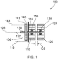
Figure 1 shows a schematic part-sectional view of an axial flux electrical machine according to a first aspect of the disclosure; -
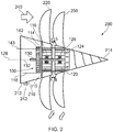
Figure 2 shows a schematic part-sectional view of a boundary layer propulsion system according to a second aspect of the disclosure; -
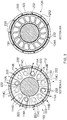
Figure 3 shows a schematic cross-sectional view of a an axial flux electrical machine according to a first aspect of the disclosure; and -
Figures 4A to 4D show schematic views of a mechanical actuator providing the relative axial movement between the first and second flux generating assemblies; -
Figures 5A to 5D show schematic views of a hydraulic actuator providing the relative axial movement between the first and second flux generating assemblies; -
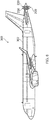
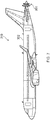
Figure 6 shows an elevational view of an aircraft comprising a boundary layer propulsion system according to the second aspect of the disclosure; and -
Figure 7 shows an alternative arrangement ofFigure 6 . - It is noted that the drawings may not be to scale. The drawings are intended to depict only typical aspects of the disclosure, and therefore should not be considered as limiting the scope of the disclosure. In the drawings, like numbering represents like elements between the drawings.
- Referring to
Figures 1 to 3 ,4A to 4D , and5A to 5D , an axial flow electrical machine according to a first embodiment of the disclosure is designated generally by thereference numeral 100, and a boundary layer propulsion system according to a second embodiment of the disclosure is designated generally by thereference numeral 200. - In the following description, the boundary
layer propulsion system 200 is described in the context of an aircraft propulsor. However, the boundarylayer propulsion system 200 may equally be applied to a marine vessel propulsor, an underwater vessel or another arrangement in which a body is to be propelled through a fluid. - The axial flow
electrical machine 100 comprises a firstflux generating assembly 110, a secondflux generating assembly 120, ashaft 130, and aspeed controller 140. - The first
flux generating assembly 110 and the secondflux generating assembly 120 are mounted co-axially in axial sequence on theshaft 130. The firstflux generating assembly 110 and the secondflux generating assembly 120 are in axial juxtaposition to one another. The firstflux generating assembly 110 is rotationally mounted on abearing assembly 116. The secondflux generating assembly 120 is rotationally mounted on abearing assembly 126. - The
speed controller 140 is arranged to modify a magnetic field that is generated by either of the firstflux generating assembly 110 or the secondflux generating assembly 120 to thereby control a rotational speed of theelectrical machine 100. - In the context of the present disclosure, the axial flux
electrical machine 100 comprises two free rotating elements, namely the first and second flux generating assemblies 110,120. Consequently, in operation the first and second flux generating assemblies 110,120 will rotate in opposite directions to one another. In other words, the first and second flux generating assemblies 110,120 will contra-rotate. - In the present arrangement the first
flux generating assembly 110 comprises a plurality ofwindings 114 in the form of a repeating circumferential array offirst coils 114A,second coils 114B, andthird coils 114C. The secondflux generating assembly 120 is formed as aninduction cage 124A. - This structure of the first and second flux generating assemblies 110,120 is illustrated in
Figure 3 . The left hand view ofFigure 3 (Section A-A) is a sectional view looking forwards (or upstream) onto the firstflux generating assembly 110. Likewise, the right hand view ofFigure 3 (Section B-B) is a sectional view looking rearwards (or downstream) onto the secondflux generating assembly 120. - In the arrangement of
Figure 1 , thespeed controller 140 is acontrol plate 142 that is configured to generate a magnetic field that can combine additively or subtractively with the magnetic field that is generated by the firstflux generating assembly 110 to modify the rotational speed of theelectrical machine 100. - In an alternative arrangement (not shown) the
control plate 142 may be positioned between the firstflux generating assembly 110 and the secondflux generating assembly 120. In this alternative arrangement, thecontrol plate 142 may be configured to modify the magnetic field that is generated by either or both of the firstflux generating assembly 110 and the secondflux generating assembly 120. - A further alternative technique for modifying the magnetic field that is generated by either of the first
flux generating assembly 110 or the secondflux generating assembly 120 is to vary theaxial separation distance 136 between the firstflux generating assembly 110 and the secondflux generating assembly 120. -
Figures 4A to 4D illustrate a first scheme for varying theseparation distance 136 between the first and second flux generating assemblies 210,220. Acontrol portion 246 is connected to anactuation portion 248. Thecontrol portion 246 generates a control signal dependent upon the desired change in rotational speed of the axial fluxelectrical machine 110. This control signal passes to theactuating portion 248 to cause a change in theseparation distance 136, and hence a change in the rotational speed of the axial fluxelectrical machine 100. - As shown in
Figure 4A , the firstflux generating assembly 210 is positioned on astatic bearing unit 248E that is fixed to astatic anchor 248A. This allows the firstflux generating assembly 210 to rotate but constrains it axially. - The second
flux generating assembly 220 is located by arotor positioning screw 248B that is concentric with thestatic bearing unit 248E. The secondflux generating assembly 220 is positioned on a slidingbearing unit 248F, which enables the secondflux generating assembly 220 to rotate about the same axis as the firstflux generating assembly 210. - In addition, the first
flux generating assembly 210 and the secondflux generating assembly 220 are located onguide elements 248D. Theguide elements 248D ensure that the relative movement of the first and second flux generating assemblies 210,220 is precisely co-axial. - Rotation of the
rotor positioning screw 248B in a first direction as shown inFigure 4A results in theseparation distance 136 being increased as shown inFigure 4B . This increase in theseparation distance 136 will decrease the magnetic field interaction between the first and second flux generating assemblies 210,220 and hence will decrease the rotational speed of both the first and second flux generating assembles 210,220. - Conversely, rotation of the
rotor positioning screw 248B in an opposite second direction as shown inFigure 4C results in theseparation distance 136 being reduced as shown inFigure 4D . This reduction in theseparation distance 136 will increase the magnetic field interaction between the first and second flux generating assemblies 210,220 and hence will increase the rotational speed of both the first and second flux generating assembles 210,220. - An alternative second scheme for varying the
separation distance 136 between the first and second flux generating assemblies 110,120 is illustrated inFigures 5A to 5D . As outlined above, acontrol portion 346 is connected to anactuating portion 348 to cause a change in theseparation distance 136. - As shown in
Figure 5A , the firstlux generating assembly 310 is mounted on astatic bearing unit 348E. In this arrangement, the static bearing unit is axially fixed to ahydraulic ram cylinder 348A. In this way, the firstflux generating assembly 310 is free to rotate but is axially constrained. - The second
flux generating assembly 320 is attached to aram cylinder 348B and is axially secured by anend flange 348C. The secondflux generating assembly 320 is positioned on a slidingbearing unit 348F. In this way, as theram cylinder 348B translates axially, the secondflux generating assembly 320 is able to freely rotate co-axially with the firstflux generating assembly 310. -
Figures 4A to 4D andFigures 5A to 5D illustrate two techniques for varying theseparation distance 136 between the first and second flux generating assemblies 110,120. The skilled person will appreciate that any further alternative arrangement for varying thisseparation distance 136 may be used. - Referring to
Figures 2 and3 , a boundary layer propulsion system according to a second embodiment of the disclosure is designated generally by thereference numeral 200. Features of the boundarylayer propulsion system 200 which correspond to those of the axial flowelectrical machine 100 have been given corresponding reference numerals for ease of reference. - The boundary
layer propulsion system 200 has an axial fluxelectrical machine 100 that is positioned in a tail section of afuselage 210 of an aircraft (not shown completely). Thefuselage 210 has anupstream end 212 and an oppositedownstream end 214. The axial fluselectrical machine 100 is positioned at thedownstream end 214 of thefuselage 210. - In this arrangement, the first
flux generating assembly 110 is positioned upstream of the secondflux generating assembly 120, with thespeed controller 140, in the form of acontrol plate 142, being positioned upstream of the firstflux generating assembly 110. - As outlined above, in an alternative configuration the
speed controller 140 may take the form of a mechanical system (illustrated inFigures 4A to 4B ) or a hydraulic system (illustrated inFigures 5A to 5B ). - The first
flux generating assembly 110 has anouter circumference 112. Arranged around thisouter circumference 112 in a circumferential array is a plurality offirst fan blades 220. Eachfirst fan blade 220 is secured to theouter circumference 112 by means of a firstblade attachment point 222. - Likewise, the second
flux generating assembly 120 has anouter circumference 122. Arranged around thisouter circumference 122 in a circumferential array is a plurality ofsecond fan blades 230. Eachsecond fan blade 230 is secured to theouter circumference 122 by means of a firstblade attachment point 232. - In the present arrangement the first and second blade attachment points 222,232 are formed with a pyriform cross-sectional profile. In an alternative arrangement, the first and second blade attachment points 222,232 may be formed with a 'fir tree' cross-sectional profile or another cross-sectional profile suitable for fan blade retention.
- In use the contra-rotation of the first and second fan blades 220,230 draws an
air flow 240 therethrough, whilst also entraining aboundary layer flow 242 passing over the surface 216 of thefuselage 210. -
Figure 6 shows anaircraft 302 comprising a boundarylayer propulsion system 200 that has been mounted at the tail of the fuselage of the aircraft. The boundarylayer propulsion system 200 comprises a downstream array offirst fan blades 220 axially adjacent to an upstream array ofsecond fan blades 230. In the arrangement ofFigure 6 , thefirst fan blades 220 are the same as thesecond fan blades 230. -
Figure 7 shows an alternative arrangement of anaircraft 310 comprising a tail-mountedboundary propulsion system 200. In the arrangement ofFigure 7 thefirst fan blades 220 have a larger diameter than thesecond fan blades 230. - In still further arrangements, the arrays of
first fan blades 220 andsecond fan blades 230 may have alternative geometrical arrangements. - Various example embodiments of the invention are described herein. Reference is made to these examples in a non-limiting sense. They are provided to illustrate more broadly applicable aspects of the invention. Various changes may be made to the invention described and equivalents may be substituted without departing from the scope of the invention. In addition, many modifications may be made to adapt a particular situation, material, composition of matter, process, process act(s) or step(s) to the objective(s), or scope of the present invention. Further, it will be appreciated by those with skill in the art that each of the individual variations described and illustrated herein has discrete components and features which may be readily separated from or combined with the features of any of the other several embodiments without departing from the scope of the present inventions. All such modifications are intended to be within the scope of claims associated with this disclosure.
- The invention includes methods that may be performed using the subject devices. The methods may comprise the act of providing such a suitable device. Such provision may be performed by the end user. In other words, the "providing" act merely requires the end user obtain, access, approach, position, set-up, activate, power-up or otherwise act to provide the requisite device in the subject method. Methods recited herein may be carried out in any order of the recited events which is logically possible, as well as in the recited order of events.
- Except where mutually exclusive, any of the features may be employed separately or in combination with any other features and the disclosure extends to and includes all combinations and sub-combinations of one or more features described herein.
- The foregoing description of various aspects of the disclosure has been presented for purposes of illustration and description. It is not intended to be exhaustive or to limit the disclosure to the precise form disclosed, and obviously, many modifications and variations are possible. Such modifications and variations that may be apparent to a person of skill in the art are included within the scope of the disclosure as defined by the accompanying claims.
Claims (15)
- An axial flux electrical machine comprising:a first flux generating assembly;a second flux generating assembly;a shaft having an axis of rotation; anda speed controller,wherein each of the first flux generating assembly and the second flux generating assembly is rotationally located on the shaft in axial juxtaposition to one another, the first flux generating assembly being axially separated from the second flux generating assembly by a separation distance, and the speed controller being configured to modify a magnetic field generated by either of the first flux generating assembly and the second flux generating assembly so as to control a rotational speed of the electrical machine.
- The axial flux electrical machine as claimed in Claim 1, wherein the first flux generating assembly comprises one or more winding portions and the second flux generating assembly comprises one or more magnetic portions, the or each winding portion corresponding to a respective one of the or each magnetic portion.
- The axial flux electrical machine as claimed in Claim 1, wherein the first flux generating assembly comprises a plurality of first flux generating portions, and the second flux generating assembly comprises a plurality of second flux generating portions, the plurality of first flux generating portions comprises an alternating circumferential array of magnetic portions and winding portions, and the plurality of second flux generating portions comprises an alternating circumferential array of magnetic portions and winding portions.
- The axial flux electrical machine as claimed in Claim 1, wherein the first flux generating assembly comprises a plurality of first flux generating portions, and the second flux generating assembly comprises a plurality of second flux generating portions, each of the plurality of first flux generating portions being the same and being selected from the group consisting of induction machine portions, permanent magnet portions, synchronous wound field portions and switched reluctance portions, and each of the plurality of second flux generating portions being the same and being selected from the group consisting of induction machine portions, permanent magnet portions, synchronous wound field portions and switched reluctance portions.
- The axial flux electrical machine as claimed in any one of Claims 1 to 4, wherein the speed controller comprises a control plate, the control plate being configured to generate a control magnetic field in opposition to a first magnetic field generated by the first flux generating assembly.
- The axial flux electrical machine as claimed in Claim 5, wherein the control plate is positioned adjacent to the first flux generating assembly.
- The axial flux electrical machine as claimed in Claim 5, wherein the control plate is positioned between the first flux generating assembly and the second flux generating assembly.
- The axial flux electrical machine as claimed in any one of Claims 1 to 7, wherein the first flux generating assembly is axially separated from the second flux generating assembly by a separation distance, and the speed controller comprises a control portion and an actuating portion, the actuating portion being configured to axially move the first flux generating assembly relative to the second flux generating assembly to thereby change the separation distance, in response to a control signal generated by the control portion.
- A propulsion system comprising:a machine body having an upstream end and an opposite downstream end;an axial flux electrical machine as claimed in any one of Claims 1 to 8;a plurality of first fan blades arranged in a circumferential array around an outer circumference of the first flux generating assembly; anda plurality of second fan blades arranged in a circumferential array around an outer circumference of the second flux generating assembly,wherein the axial flux electrical machine is positioned at the downstream end of the machine body such that a fluid flow passing over the machine body, from the upstream end to the downstream end, is successively drawn through the first fan blade array and the second fan blade array to thereby entrain the flow passing over the surface of the machine body and thereby to accelerate the flow.
- A propulsion system as claimed in Claim 9, wherein the machine body is an aircraft.
- A method of controlling a rotational speed of an axial flux electrical machine, the method comprising the steps of:providing a first rotatable flux generating assembly and a second rotatable flux generating assembly;positioning the first rotatable flux generating assembly and the second rotatable flux generating assembly in axial juxtaposition on a shaft;providing excitation energy to one of the first rotatable flux generating assembly and the second rotatable flux generating assembly; andusing a speed controller to vary a magnetic field generated by one of the first flux rotatable generating assembly and the second rotatable flux generating assembly, thereby controlling the rotational speed of the electrical machine.
- The method as claimed in Claim 11, wherein the step of using a speed controller to vary a magnetic field generated by one of the first rotatable flux generating assembly and the second rotatable flux generating assembly comprises the steps of:positioning a control plate adjacent to the first flux rotatable generating assembly;generating a control magnetic field from the control plate, the control magnetic field being in opposition to a first magnetic field generated by the first rotatable flux generating assembly; andvarying the control magnetic field in response to a user input, thereby controlling the rotational speed of the electrical machine.
- The method as claimed in Claim 12, wherein the step of positioning a control plate adjacent to the first rotatable flux generating assembly comprises the step of:positioning a control plate between the first rotatable flux generating assembly and the second rotatable flux generating assembly.
- The method as claimed in Claim 11, wherein the first rotatable flux generating assembly is axially separated from the second rotatable flux generating assembly by a separation distance, and the step of using a speed controller to vary a magnetic field generated by one of the first rotatable flux generating assembly and the second rotatable flux generating assembly, comprises the steps of:providing a control portion that generates a control signal in response to a user input; andproviding an actuating portion that is configured to axially move the first rotatable flux generating assembly relative to the second rotatable flux generating assembly to thereby change the separation distance, in response to the control signal, the change in separation distance resulting in a change to a magnetic field generated by one of the first rotatable flux generating assembly and the second rotatable flux generating assembly, thereby controlling the rotational speed of the electrical machine.
- A computer program that, when read by a computer, causes performance of the method as claimed in any of Claims 11 to 14.
Applications Claiming Priority (1)
| Application Number | Priority Date | Filing Date | Title |
|---|---|---|---|
| GBGB1704268.0A GB201704268D0 (en) | 2017-03-17 | 2017-03-17 | An electrical machine |
Publications (2)
| Publication Number | Publication Date |
|---|---|
| EP3376648A1 true EP3376648A1 (en) | 2018-09-19 |
| EP3376648B1 EP3376648B1 (en) | 2020-01-01 |
Family
ID=58688414
Family Applications (1)
| Application Number | Title | Priority Date | Filing Date |
|---|---|---|---|
| EP18157534.1A Active EP3376648B1 (en) | 2017-03-17 | 2018-02-20 | An electrical machine |
Country Status (3)
| Country | Link |
|---|---|
| US (1) | US10700580B2 (en) |
| EP (1) | EP3376648B1 (en) |
| GB (1) | GB201704268D0 (en) |
Cited By (1)
| Publication number | Priority date | Publication date | Assignee | Title |
|---|---|---|---|---|
| WO2020070392A1 (en) * | 2018-10-05 | 2020-04-09 | Piccaluga, Pierre | Electric motor with two counter-rotating rotors |
Families Citing this family (4)
| Publication number | Priority date | Publication date | Assignee | Title |
|---|---|---|---|---|
| GB201702822D0 (en) * | 2017-02-22 | 2017-04-05 | Rolls Royce Plc | A propulsor |
| FR3091060B1 (en) * | 2018-12-20 | 2020-12-04 | Safran Helicopter Engines | Electric machine with device for forced demagnetization of permanent magnets |
| US11735988B2 (en) * | 2019-01-31 | 2023-08-22 | General Electric Company | Dual rotor electric machine |
| GB201902095D0 (en) * | 2019-02-15 | 2019-04-03 | Rolls Royce Plc | Electric turbomachine |
Citations (4)
| Publication number | Priority date | Publication date | Assignee | Title |
|---|---|---|---|---|
| JPH07174067A (en) * | 1992-01-20 | 1995-07-11 | Bitsugusu:Kk | Double rotor wind power generator |
| US20050218738A1 (en) * | 2003-11-12 | 2005-10-06 | Hsu John S | Hybrid-secondary uncluttered permanent magnet machine and method |
| WO2007095254A1 (en) * | 2006-02-10 | 2007-08-23 | The Timken Company | Electric motor with field weakening |
| GB2542184A (en) * | 2015-09-11 | 2017-03-15 | Rolls Royce Plc | Aircraft comprising a boundary layer ingesting propulsor |
Family Cites Families (5)
| Publication number | Priority date | Publication date | Assignee | Title |
|---|---|---|---|---|
| NL286732A (en) | 1961-12-16 | |||
| GB2466436A (en) * | 2008-12-18 | 2010-06-23 | Scimar Engineering Ltd | Axial flux motor and generator assemblies |
| US20140252913A1 (en) * | 2013-03-08 | 2014-09-11 | Everette Energy, LLC | Single phase switched reluctance machine with axial flux path |
| FR3030931B1 (en) * | 2014-12-18 | 2017-12-08 | Airbus Helicopters | ELECTRIC MACHINE WITH EXCITATION SEPARATE WITH AT LEAST TWO INDUCTIONS AND INDUCTOR |
| US10608509B2 (en) * | 2016-10-17 | 2020-03-31 | Roul Delroy MARTIN | Rotatable electric machines |
-
2017
- 2017-03-17 GB GBGB1704268.0A patent/GB201704268D0/en not_active Ceased
-
2018
- 2018-02-20 EP EP18157534.1A patent/EP3376648B1/en active Active
- 2018-03-08 US US15/915,229 patent/US10700580B2/en active Active
Patent Citations (4)
| Publication number | Priority date | Publication date | Assignee | Title |
|---|---|---|---|---|
| JPH07174067A (en) * | 1992-01-20 | 1995-07-11 | Bitsugusu:Kk | Double rotor wind power generator |
| US20050218738A1 (en) * | 2003-11-12 | 2005-10-06 | Hsu John S | Hybrid-secondary uncluttered permanent magnet machine and method |
| WO2007095254A1 (en) * | 2006-02-10 | 2007-08-23 | The Timken Company | Electric motor with field weakening |
| GB2542184A (en) * | 2015-09-11 | 2017-03-15 | Rolls Royce Plc | Aircraft comprising a boundary layer ingesting propulsor |
Cited By (1)
| Publication number | Priority date | Publication date | Assignee | Title |
|---|---|---|---|---|
| WO2020070392A1 (en) * | 2018-10-05 | 2020-04-09 | Piccaluga, Pierre | Electric motor with two counter-rotating rotors |
Also Published As
| Publication number | Publication date |
|---|---|
| GB201704268D0 (en) | 2017-05-03 |
| US10700580B2 (en) | 2020-06-30 |
| EP3376648B1 (en) | 2020-01-01 |
| US20180269760A1 (en) | 2018-09-20 |
Similar Documents
| Publication | Publication Date | Title |
|---|---|---|
| US10700580B2 (en) | Electrical machine | |
| US3900274A (en) | Remote controlled actuation system for the rotor of a gas turbine engine | |
| CN108928493B (en) | Propulsion system for aircraft and method for operating same | |
| US9143023B1 (en) | Electromagnetic propulsive motor | |
| US20200227966A1 (en) | Turbomachine | |
| JP5563642B2 (en) | Helicopter electric tail rotor | |
| US6914344B2 (en) | Integrated starter/generator for a turbomachine | |
| US5282719A (en) | Quad mode fan pitch actuation system for a gas turbine engine | |
| US10218232B2 (en) | High speed electric machine | |
| CN110486188B (en) | Electric conduit fan | |
| US9963981B2 (en) | Pitch change mechanism for shrouded fan with low fan pressure ratio | |
| US20170297728A1 (en) | Propulsion engine for an aircraft | |
| US6476534B1 (en) | Permanent magnet phase-control motor | |
| WO2019243767A1 (en) | Electric engine | |
| US9140187B2 (en) | Magnetic de-icing | |
| EP3569856B1 (en) | Electric ducted fan | |
| US20200216183A1 (en) | Rotary propulsion systems and methods of propelling vehicles using rotary propulsion systems | |
| CN114844314A (en) | Rotating electrical machine | |
| CN113054796A (en) | Starter/generator system | |
| US9447750B2 (en) | Propulsion engine | |
| DE102013009677B4 (en) | Propulsion unit for an aircraft | |
| US20200195089A1 (en) | Electric propulsion system | |
| EP4023558A1 (en) | Aeronautical propulsion device | |
| AU2021246540A1 (en) | Fluid drawing induction motor |
Legal Events
| Date | Code | Title | Description |
|---|---|---|---|
| PUAI | Public reference made under article 153(3) epc to a published international application that has entered the european phase |
Free format text: ORIGINAL CODE: 0009012 |
|
| STAA | Information on the status of an ep patent application or granted ep patent |
Free format text: STATUS: THE APPLICATION HAS BEEN PUBLISHED |
|
| AK | Designated contracting states |
Kind code of ref document: A1 Designated state(s): AL AT BE BG CH CY CZ DE DK EE ES FI FR GB GR HR HU IE IS IT LI LT LU LV MC MK MT NL NO PL PT RO RS SE SI SK SM TR |
|
| AX | Request for extension of the european patent |
Extension state: BA ME |
|
| STAA | Information on the status of an ep patent application or granted ep patent |
Free format text: STATUS: REQUEST FOR EXAMINATION WAS MADE |
|
| 17P | Request for examination filed |
Effective date: 20180925 |
|
| RBV | Designated contracting states (corrected) |
Designated state(s): AL AT BE BG CH CY CZ DE DK EE ES FI FR GB GR HR HU IE IS IT LI LT LU LV MC MK MT NL NO PL PT RO RS SE SI SK SM TR |
|
| GRAP | Despatch of communication of intention to grant a patent |
Free format text: ORIGINAL CODE: EPIDOSNIGR1 |
|
| STAA | Information on the status of an ep patent application or granted ep patent |
Free format text: STATUS: GRANT OF PATENT IS INTENDED |
|
| RIC1 | Information provided on ipc code assigned before grant |
Ipc: B64C 21/00 20060101ALN20190913BHEP Ipc: H02K 21/24 20060101ALI20190913BHEP Ipc: H02K 16/00 20060101AFI20190913BHEP Ipc: H02K 21/02 20060101ALI20190913BHEP Ipc: B64D 27/24 20060101ALN20190913BHEP Ipc: H02K 1/22 20060101ALN20190913BHEP Ipc: H02K 1/27 20060101ALI20190913BHEP |
|
| INTG | Intention to grant announced |
Effective date: 20191001 |
|
| GRAS | Grant fee paid |
Free format text: ORIGINAL CODE: EPIDOSNIGR3 |
|
| GRAA | (expected) grant |
Free format text: ORIGINAL CODE: 0009210 |
|
| STAA | Information on the status of an ep patent application or granted ep patent |
Free format text: STATUS: THE PATENT HAS BEEN GRANTED |
|
| AK | Designated contracting states |
Kind code of ref document: B1 Designated state(s): AL AT BE BG CH CY CZ DE DK EE ES FI FR GB GR HR HU IE IS IT LI LT LU LV MC MK MT NL NO PL PT RO RS SE SI SK SM TR |
|
| REG | Reference to a national code |
Ref country code: GB Ref legal event code: FG4D |
|
| REG | Reference to a national code |
Ref country code: CH Ref legal event code: EP Ref country code: AT Ref legal event code: REF Ref document number: 1221032 Country of ref document: AT Kind code of ref document: T Effective date: 20200115 |
|
| REG | Reference to a national code |
Ref country code: IE Ref legal event code: FG4D |
|
| REG | Reference to a national code |
Ref country code: DE Ref legal event code: R096 Ref document number: 602018001815 Country of ref document: DE |
|
| REG | Reference to a national code |
Ref country code: CH Ref legal event code: PK Free format text: BERICHTIGUNGEN |
|
| RIN2 | Information on inventor provided after grant (corrected) |
Inventor name: PALMER, CHLOE JO |
|
| RAP2 | Party data changed (patent owner data changed or rights of a patent transferred) |
Owner name: ROLLS-ROYCE PLC |
|
| REG | Reference to a national code |
Ref country code: NL Ref legal event code: MP Effective date: 20200101 |
|
| REG | Reference to a national code |
Ref country code: LT Ref legal event code: MG4D |
|
| PG25 | Lapsed in a contracting state [announced via postgrant information from national office to epo] |
Ref country code: RS Free format text: LAPSE BECAUSE OF FAILURE TO SUBMIT A TRANSLATION OF THE DESCRIPTION OR TO PAY THE FEE WITHIN THE PRESCRIBED TIME-LIMIT Effective date: 20200101 Ref country code: FI Free format text: LAPSE BECAUSE OF FAILURE TO SUBMIT A TRANSLATION OF THE DESCRIPTION OR TO PAY THE FEE WITHIN THE PRESCRIBED TIME-LIMIT Effective date: 20200101 Ref country code: NO Free format text: LAPSE BECAUSE OF FAILURE TO SUBMIT A TRANSLATION OF THE DESCRIPTION OR TO PAY THE FEE WITHIN THE PRESCRIBED TIME-LIMIT Effective date: 20200401 Ref country code: NL Free format text: LAPSE BECAUSE OF FAILURE TO SUBMIT A TRANSLATION OF THE DESCRIPTION OR TO PAY THE FEE WITHIN THE PRESCRIBED TIME-LIMIT Effective date: 20200101 Ref country code: LT Free format text: LAPSE BECAUSE OF FAILURE TO SUBMIT A TRANSLATION OF THE DESCRIPTION OR TO PAY THE FEE WITHIN THE PRESCRIBED TIME-LIMIT Effective date: 20200101 Ref country code: PT Free format text: LAPSE BECAUSE OF FAILURE TO SUBMIT A TRANSLATION OF THE DESCRIPTION OR TO PAY THE FEE WITHIN THE PRESCRIBED TIME-LIMIT Effective date: 20200527 |
|
| PG25 | Lapsed in a contracting state [announced via postgrant information from national office to epo] |
Ref country code: IS Free format text: LAPSE BECAUSE OF FAILURE TO SUBMIT A TRANSLATION OF THE DESCRIPTION OR TO PAY THE FEE WITHIN THE PRESCRIBED TIME-LIMIT Effective date: 20200501 Ref country code: BG Free format text: LAPSE BECAUSE OF FAILURE TO SUBMIT A TRANSLATION OF THE DESCRIPTION OR TO PAY THE FEE WITHIN THE PRESCRIBED TIME-LIMIT Effective date: 20200401 Ref country code: HR Free format text: LAPSE BECAUSE OF FAILURE TO SUBMIT A TRANSLATION OF THE DESCRIPTION OR TO PAY THE FEE WITHIN THE PRESCRIBED TIME-LIMIT Effective date: 20200101 Ref country code: SE Free format text: LAPSE BECAUSE OF FAILURE TO SUBMIT A TRANSLATION OF THE DESCRIPTION OR TO PAY THE FEE WITHIN THE PRESCRIBED TIME-LIMIT Effective date: 20200101 Ref country code: LV Free format text: LAPSE BECAUSE OF FAILURE TO SUBMIT A TRANSLATION OF THE DESCRIPTION OR TO PAY THE FEE WITHIN THE PRESCRIBED TIME-LIMIT Effective date: 20200101 Ref country code: GR Free format text: LAPSE BECAUSE OF FAILURE TO SUBMIT A TRANSLATION OF THE DESCRIPTION OR TO PAY THE FEE WITHIN THE PRESCRIBED TIME-LIMIT Effective date: 20200402 |
|
| REG | Reference to a national code |
Ref country code: DE Ref legal event code: R097 Ref document number: 602018001815 Country of ref document: DE |
|
| REG | Reference to a national code |
Ref country code: BE Ref legal event code: MM Effective date: 20200229 |
|
| PG25 | Lapsed in a contracting state [announced via postgrant information from national office to epo] |
Ref country code: DK Free format text: LAPSE BECAUSE OF FAILURE TO SUBMIT A TRANSLATION OF THE DESCRIPTION OR TO PAY THE FEE WITHIN THE PRESCRIBED TIME-LIMIT Effective date: 20200101 Ref country code: ES Free format text: LAPSE BECAUSE OF FAILURE TO SUBMIT A TRANSLATION OF THE DESCRIPTION OR TO PAY THE FEE WITHIN THE PRESCRIBED TIME-LIMIT Effective date: 20200101 Ref country code: MC Free format text: LAPSE BECAUSE OF FAILURE TO SUBMIT A TRANSLATION OF THE DESCRIPTION OR TO PAY THE FEE WITHIN THE PRESCRIBED TIME-LIMIT Effective date: 20200101 Ref country code: SK Free format text: LAPSE BECAUSE OF FAILURE TO SUBMIT A TRANSLATION OF THE DESCRIPTION OR TO PAY THE FEE WITHIN THE PRESCRIBED TIME-LIMIT Effective date: 20200101 Ref country code: CZ Free format text: LAPSE BECAUSE OF FAILURE TO SUBMIT A TRANSLATION OF THE DESCRIPTION OR TO PAY THE FEE WITHIN THE PRESCRIBED TIME-LIMIT Effective date: 20200101 Ref country code: RO Free format text: LAPSE BECAUSE OF FAILURE TO SUBMIT A TRANSLATION OF THE DESCRIPTION OR TO PAY THE FEE WITHIN THE PRESCRIBED TIME-LIMIT Effective date: 20200101 Ref country code: LU Free format text: LAPSE BECAUSE OF NON-PAYMENT OF DUE FEES Effective date: 20200220 Ref country code: SM Free format text: LAPSE BECAUSE OF FAILURE TO SUBMIT A TRANSLATION OF THE DESCRIPTION OR TO PAY THE FEE WITHIN THE PRESCRIBED TIME-LIMIT Effective date: 20200101 Ref country code: EE Free format text: LAPSE BECAUSE OF FAILURE TO SUBMIT A TRANSLATION OF THE DESCRIPTION OR TO PAY THE FEE WITHIN THE PRESCRIBED TIME-LIMIT Effective date: 20200101 |
|
| PLBE | No opposition filed within time limit |
Free format text: ORIGINAL CODE: 0009261 |
|
| STAA | Information on the status of an ep patent application or granted ep patent |
Free format text: STATUS: NO OPPOSITION FILED WITHIN TIME LIMIT |
|
| REG | Reference to a national code |
Ref country code: AT Ref legal event code: MK05 Ref document number: 1221032 Country of ref document: AT Kind code of ref document: T Effective date: 20200101 |
|
| 26N | No opposition filed |
Effective date: 20201002 |
|
| PG25 | Lapsed in a contracting state [announced via postgrant information from national office to epo] |
Ref country code: IT Free format text: LAPSE BECAUSE OF FAILURE TO SUBMIT A TRANSLATION OF THE DESCRIPTION OR TO PAY THE FEE WITHIN THE PRESCRIBED TIME-LIMIT Effective date: 20200101 Ref country code: IE Free format text: LAPSE BECAUSE OF NON-PAYMENT OF DUE FEES Effective date: 20200220 Ref country code: AT Free format text: LAPSE BECAUSE OF FAILURE TO SUBMIT A TRANSLATION OF THE DESCRIPTION OR TO PAY THE FEE WITHIN THE PRESCRIBED TIME-LIMIT Effective date: 20200101 |
|
| PG25 | Lapsed in a contracting state [announced via postgrant information from national office to epo] |
Ref country code: BE Free format text: LAPSE BECAUSE OF NON-PAYMENT OF DUE FEES Effective date: 20200229 Ref country code: SI Free format text: LAPSE BECAUSE OF FAILURE TO SUBMIT A TRANSLATION OF THE DESCRIPTION OR TO PAY THE FEE WITHIN THE PRESCRIBED TIME-LIMIT Effective date: 20200101 Ref country code: PL Free format text: LAPSE BECAUSE OF FAILURE TO SUBMIT A TRANSLATION OF THE DESCRIPTION OR TO PAY THE FEE WITHIN THE PRESCRIBED TIME-LIMIT Effective date: 20200101 |
|
| PG25 | Lapsed in a contracting state [announced via postgrant information from national office to epo] |
Ref country code: LI Free format text: LAPSE BECAUSE OF NON-PAYMENT OF DUE FEES Effective date: 20210228 Ref country code: CH Free format text: LAPSE BECAUSE OF NON-PAYMENT OF DUE FEES Effective date: 20210228 |
|
| PG25 | Lapsed in a contracting state [announced via postgrant information from national office to epo] |
Ref country code: TR Free format text: LAPSE BECAUSE OF FAILURE TO SUBMIT A TRANSLATION OF THE DESCRIPTION OR TO PAY THE FEE WITHIN THE PRESCRIBED TIME-LIMIT Effective date: 20200101 Ref country code: MT Free format text: LAPSE BECAUSE OF FAILURE TO SUBMIT A TRANSLATION OF THE DESCRIPTION OR TO PAY THE FEE WITHIN THE PRESCRIBED TIME-LIMIT Effective date: 20200101 Ref country code: CY Free format text: LAPSE BECAUSE OF FAILURE TO SUBMIT A TRANSLATION OF THE DESCRIPTION OR TO PAY THE FEE WITHIN THE PRESCRIBED TIME-LIMIT Effective date: 20200101 |
|
| PG25 | Lapsed in a contracting state [announced via postgrant information from national office to epo] |
Ref country code: MK Free format text: LAPSE BECAUSE OF FAILURE TO SUBMIT A TRANSLATION OF THE DESCRIPTION OR TO PAY THE FEE WITHIN THE PRESCRIBED TIME-LIMIT Effective date: 20200101 Ref country code: AL Free format text: LAPSE BECAUSE OF FAILURE TO SUBMIT A TRANSLATION OF THE DESCRIPTION OR TO PAY THE FEE WITHIN THE PRESCRIBED TIME-LIMIT Effective date: 20200101 |
|
| P01 | Opt-out of the competence of the unified patent court (upc) registered |
Effective date: 20230528 |
|
| PGFP | Annual fee paid to national office [announced via postgrant information from national office to epo] |
Ref country code: FR Payment date: 20250224 Year of fee payment: 8 |
|
| PGFP | Annual fee paid to national office [announced via postgrant information from national office to epo] |
Ref country code: GB Payment date: 20260223 Year of fee payment: 9 |
|
| PGFP | Annual fee paid to national office [announced via postgrant information from national office to epo] |
Ref country code: DE Payment date: 20260220 Year of fee payment: 9 |