EP3376601A1 - Connector - Google Patents
Connector Download PDFInfo
- Publication number
- EP3376601A1 EP3376601A1 EP18152549.4A EP18152549A EP3376601A1 EP 3376601 A1 EP3376601 A1 EP 3376601A1 EP 18152549 A EP18152549 A EP 18152549A EP 3376601 A1 EP3376601 A1 EP 3376601A1
- Authority
- EP
- European Patent Office
- Prior art keywords
- projection
- flexible substrate
- contact
- base member
- blade member
- Prior art date
- Legal status (The legal status is an assumption and is not a legal conclusion. Google has not performed a legal analysis and makes no representation as to the accuracy of the status listed.)
- Granted
Links
Images







Classifications
-
- H—ELECTRICITY
- H01—ELECTRIC ELEMENTS
- H01R—ELECTRICALLY-CONDUCTIVE CONNECTIONS; STRUCTURAL ASSOCIATIONS OF A PLURALITY OF MUTUALLY-INSULATED ELECTRICAL CONNECTING ELEMENTS; COUPLING DEVICES; CURRENT COLLECTORS
- H01R12/00—Structural associations of a plurality of mutually-insulated electrical connecting elements, specially adapted for printed circuits, e.g. printed circuit boards [PCB], flat or ribbon cables, or like generally planar structures, e.g. terminal strips, terminal blocks; Coupling devices specially adapted for printed circuits, flat or ribbon cables, or like generally planar structures; Terminals specially adapted for contact with, or insertion into, printed circuits, flat or ribbon cables, or like generally planar structures
- H01R12/50—Fixed connections
- H01R12/59—Fixed connections for flexible printed circuits, flat or ribbon cables or like structures
- H01R12/61—Fixed connections for flexible printed circuits, flat or ribbon cables or like structures connecting to flexible printed circuits, flat or ribbon cables or like structures
- H01R12/613—Fixed connections for flexible printed circuits, flat or ribbon cables or like structures connecting to flexible printed circuits, flat or ribbon cables or like structures by means of interconnecting elements
- H01R12/616—Fixed connections for flexible printed circuits, flat or ribbon cables or like structures connecting to flexible printed circuits, flat or ribbon cables or like structures by means of interconnecting elements having contacts penetrating insulation for making contact with conductors, e.g. needle points
-
- H—ELECTRICITY
- H01—ELECTRIC ELEMENTS
- H01R—ELECTRICALLY-CONDUCTIVE CONNECTIONS; STRUCTURAL ASSOCIATIONS OF A PLURALITY OF MUTUALLY-INSULATED ELECTRICAL CONNECTING ELEMENTS; COUPLING DEVICES; CURRENT COLLECTORS
- H01R12/00—Structural associations of a plurality of mutually-insulated electrical connecting elements, specially adapted for printed circuits, e.g. printed circuit boards [PCB], flat or ribbon cables, or like generally planar structures, e.g. terminal strips, terminal blocks; Coupling devices specially adapted for printed circuits, flat or ribbon cables, or like generally planar structures; Terminals specially adapted for contact with, or insertion into, printed circuits, flat or ribbon cables, or like generally planar structures
- H01R12/50—Fixed connections
- H01R12/59—Fixed connections for flexible printed circuits, flat or ribbon cables or like structures
- H01R12/65—Fixed connections for flexible printed circuits, flat or ribbon cables or like structures characterised by the terminal
- H01R12/67—Fixed connections for flexible printed circuits, flat or ribbon cables or like structures characterised by the terminal insulation penetrating terminals
-
- H—ELECTRICITY
- H01—ELECTRIC ELEMENTS
- H01R—ELECTRICALLY-CONDUCTIVE CONNECTIONS; STRUCTURAL ASSOCIATIONS OF A PLURALITY OF MUTUALLY-INSULATED ELECTRICAL CONNECTING ELEMENTS; COUPLING DEVICES; CURRENT COLLECTORS
- H01R12/00—Structural associations of a plurality of mutually-insulated electrical connecting elements, specially adapted for printed circuits, e.g. printed circuit boards [PCB], flat or ribbon cables, or like generally planar structures, e.g. terminal strips, terminal blocks; Coupling devices specially adapted for printed circuits, flat or ribbon cables, or like generally planar structures; Terminals specially adapted for contact with, or insertion into, printed circuits, flat or ribbon cables, or like generally planar structures
- H01R12/50—Fixed connections
- H01R12/59—Fixed connections for flexible printed circuits, flat or ribbon cables or like structures
- H01R12/65—Fixed connections for flexible printed circuits, flat or ribbon cables or like structures characterised by the terminal
- H01R12/67—Fixed connections for flexible printed circuits, flat or ribbon cables or like structures characterised by the terminal insulation penetrating terminals
- H01R12/68—Fixed connections for flexible printed circuits, flat or ribbon cables or like structures characterised by the terminal insulation penetrating terminals comprising deformable portions
-
- H—ELECTRICITY
- H01—ELECTRIC ELEMENTS
- H01R—ELECTRICALLY-CONDUCTIVE CONNECTIONS; STRUCTURAL ASSOCIATIONS OF A PLURALITY OF MUTUALLY-INSULATED ELECTRICAL CONNECTING ELEMENTS; COUPLING DEVICES; CURRENT COLLECTORS
- H01R12/00—Structural associations of a plurality of mutually-insulated electrical connecting elements, specially adapted for printed circuits, e.g. printed circuit boards [PCB], flat or ribbon cables, or like generally planar structures, e.g. terminal strips, terminal blocks; Coupling devices specially adapted for printed circuits, flat or ribbon cables, or like generally planar structures; Terminals specially adapted for contact with, or insertion into, printed circuits, flat or ribbon cables, or like generally planar structures
- H01R12/70—Coupling devices
- H01R12/77—Coupling devices for flexible printed circuits, flat or ribbon cables or like structures
- H01R12/771—Details
-
- H—ELECTRICITY
- H01—ELECTRIC ELEMENTS
- H01R—ELECTRICALLY-CONDUCTIVE CONNECTIONS; STRUCTURAL ASSOCIATIONS OF A PLURALITY OF MUTUALLY-INSULATED ELECTRICAL CONNECTING ELEMENTS; COUPLING DEVICES; CURRENT COLLECTORS
- H01R12/00—Structural associations of a plurality of mutually-insulated electrical connecting elements, specially adapted for printed circuits, e.g. printed circuit boards [PCB], flat or ribbon cables, or like generally planar structures, e.g. terminal strips, terminal blocks; Coupling devices specially adapted for printed circuits, flat or ribbon cables, or like generally planar structures; Terminals specially adapted for contact with, or insertion into, printed circuits, flat or ribbon cables, or like generally planar structures
- H01R12/70—Coupling devices
- H01R12/77—Coupling devices for flexible printed circuits, flat or ribbon cables or like structures
- H01R12/777—Coupling parts carrying pins, blades or analogous contacts
-
- H—ELECTRICITY
- H01—ELECTRIC ELEMENTS
- H01R—ELECTRICALLY-CONDUCTIVE CONNECTIONS; STRUCTURAL ASSOCIATIONS OF A PLURALITY OF MUTUALLY-INSULATED ELECTRICAL CONNECTING ELEMENTS; COUPLING DEVICES; CURRENT COLLECTORS
- H01R13/00—Details of coupling devices of the kinds covered by groups H01R12/70 or H01R24/00 - H01R33/00
- H01R13/46—Bases; Cases
- H01R13/502—Bases; Cases composed of different pieces
-
- H—ELECTRICITY
- H01—ELECTRIC ELEMENTS
- H01R—ELECTRICALLY-CONDUCTIVE CONNECTIONS; STRUCTURAL ASSOCIATIONS OF A PLURALITY OF MUTUALLY-INSULATED ELECTRICAL CONNECTING ELEMENTS; COUPLING DEVICES; CURRENT COLLECTORS
- H01R12/00—Structural associations of a plurality of mutually-insulated electrical connecting elements, specially adapted for printed circuits, e.g. printed circuit boards [PCB], flat or ribbon cables, or like generally planar structures, e.g. terminal strips, terminal blocks; Coupling devices specially adapted for printed circuits, flat or ribbon cables, or like generally planar structures; Terminals specially adapted for contact with, or insertion into, printed circuits, flat or ribbon cables, or like generally planar structures
- H01R12/50—Fixed connections
- H01R12/59—Fixed connections for flexible printed circuits, flat or ribbon cables or like structures
- H01R12/592—Fixed connections for flexible printed circuits, flat or ribbon cables or like structures connections to contact elements
Definitions
- the present invention relates to a connector, particularly to a connector to be mounted on a flexible substrate in which a conductive portion is exposed at least on the top surface of the flexible substrate.
- JP 2005-63872 A discloses a connector 1 as shown in FIG. 37 .
- the connector 1 is to be installed on a flat cable 2 and includes a base 3 and a cover 4 that are made of resin and make up a housing, a metallic plate 6 that is fitted in the base 3 and has a slot 5 formed therein, and a metallic connection portion 8 that has a piercing portion 7.
- the flat cable 2 is sandwiched between the base 3 and the cover 4 and, at the same time, in contact with a surface of the plate 6.
- connection portion 8 and the flat conductor 9 are electrically connected to each other.
- the flat conductor 9 is covered by an insulating material 10 of the flat cable 2 and, accordingly, when the flat cable 2 is pierced with the piercing portion 7 of the connection portion 8, the insulating material 10 is also sheared together with the flat conductor 9. Consequently, a sheared piece of the insulating material 10 may be caught between the piercing portion 7 and the flat conductor 9, resulting in a poor contact between the piercing portion 7 and the fractured extension portion 9A of the flat conductor 9. When such a poor contact occurs, the reliability of electrical connection between the connection portion 8 and the flat conductor 9 decreases.
- the present invention has been made in order to solve the conventional problem described above and an object of the present invention is to provide a connector having excellent reliability in electrical connection with a conductive portion of a flexible substrate.
- a connector according to a first invention is a connector to be mounted on a flexible substrate that has a top surface and a bottom surface facing in opposite directions to each other and has a conductive portion exposed at least on the top surface, the connector comprising:
- a connector according to a second invention is a connector to be mounted on a flexible substrate that has a top surface and a bottom surface facing in opposite directions to each other and has a conductive portion exposed at least on the top surface, the connector comprising:
- FIGS. 1 and 2 show a connector 11 according to Embodiment 1.
- the connector 11 is used as, for example, a garment-side connector part used for fitting a wearable device and is mounted on a flexible substrate 21.
- the connector 11 includes a housing 12 disposed on the flexible substrate 21, and four contacts 13.
- the housing 12 has a recess 12A.
- the four contacts 13 project perpendicularly to the flexible substrate 21 within the recess 12A of the housing 12.
- the flexible substrate 21 is defined as extending along an XY plane, and the direction in which the contacts 13 project is referred to as "+Z direction.”
- the connector 11 further includes a base member 14 disposed on the -Z direction side of the flexible substrate 21 and is mounted on the flexible substrate 21 as sandwiching the flexible substrate 21 between the housing 12 and the base member 14.
- the flexible substrate 21 has a top surface 21A facing in the +Z direction and a bottom surface 21B facing in the -Z direction, and four flexible conductors 21C serving as conductive portions are exposed on the top surface 21A.
- the four flexible conductors 21C correspond to the four contacts 13 and each take on a strip shape extending in the Y direction.
- the flexible substrate 21 is further provided with two through-holes 21D.
- the housing 12 is made of an insulating material such as an insulating resin and is provided with four contact through-holes 12B in the recess 12A opening in the +Z direction.
- the four contact through-holes 12B separately correspond to the four contacts 13.
- Two recessed post accommodating portions 12D are formed at positions outside the recess 12A in the X direction and the Y direction and on a -Z direction-side surface 12C of the housing 12.
- Each of the four contacts 13 is a plug-type contact made of a conductive material such as a metal and has a tubular portion 13A having a cylindrical shape extending in the Z direction and a flange 13B extending from a -Z directional end of the tubular portion 13A along an XY plane.
- the flange 13B has a second surface 13C facing in the -Z direction.
- the base member 14 is made of an insulating material such as an insulating resin and has a flat plate portion 14A.
- the flat plate portion 14A has a first surface 14B facing in the +Z direction.
- Four projections 14C project on the first surface 14B.
- two housing fixing posts 14D project on the first surface 14B of the flat plate portion 14A.
- the base member 14 is further provided with four slits 14F that separately extend from a surface 14E, facing in the -Z direction, of the flat plate portion 14A and penetrate the four projections 14C in the Z direction.
- the connector 11 further includes four blade members 15 separately inserted in the four slits 14F of the base member 14.
- the four contact through-holes 12B of the housing 12, the four flexible conductors 21C of the flexible substrate 21 and the four projections 14C of the base member 14 are arranged to correspond to each other in position.
- the two post accommodating portions 12D of the housing 12, the two through-holes 21D of the flexible substrate 21 and the two housing fixing posts 14D of the base member 14 are arranged to correspond to each other in position.
- the through-holes 21D of the flexible substrate 21 have an inside diameter slightly larger than the outside diameter of the housing fixing posts 14D of the base member 14 to allow smooth insertion of the housing fixing posts 14D.
- the post accommodating portions 12D of the housing 12 have an inside diameter slightly smaller than the outside diameter of the housing fixing posts 14D of the base member 14, and by press-fitting the housing fixing posts 14D into the post accommodating portions 12D, the housing 12 and the base member 14 are fixed to each other.
- the contact through-holes 12B of the housing 12 have an inside diameter larger than the outside diameter of the tubular portions 13A of the contacts 13 and smaller than the outside diameter of the flanges 13B to allow smooth insertion of the tubular portions 13A of the contacts 13.
- the tubular portion 13A of the contact 13 has a cylindrical shape with its +Z directional end being closed, the flange 13B is formed integrally with the -Z directional end of the tubular portion 13A, and a projection accommodating portion 13D of recess shape is provided in the second surface 13C of the flange 13B facing in the -Z direction.
- the projection accommodating portion 13D is formed inside the tubular portion 13A so as to have an opening end at the second surface 13C of the flange 13B.
- the projection accommodating portion 13D of the contact 13 has an inside diameter smaller than a value obtained by adding a double of the sum of the thickness of the flexible substrate 21 at the portion where the flexible conductor 21C is exposed and the thickness of the flexible conductor 21C to the outside diameter of the projection 14C of the base member 14.
- the contact 13 as above can be manufactured by, for example, stamping a metal plate.
- the projection 14C of the base member 14 has a columnar shape extending in the Z direction and has outer surfaces 14G extending parallel to the direction in which the projection 14C projects.
- the projection 14C is divided into two parts, a +Y directional part and a -Y directional part, by the slit 14F formed along an XZ plane passing the central axis of the columnar shape.
- the blade member 15 is a flat plate member made of a metal material and extending along an XZ plane.
- the blade member 15 has, at its +Z directional end, a pointed portion 15A that is pointed in the +Z direction and also has, near its -Z directional end, a pair of protrusions 15B separately protruding in the +X and -X directions.
- the size of the blade member 15 in the Z direction is set to be larger than the total size, in the Z direction, of the flat plate portion 14A and the projection 14C of the base member 14.
- the pointed portion 15A is formed to be narrower in width in the X and Y directions as advancing in the +Z direction.
- the four blade members 15 are attached to the base member 14. As shown in FIG. 4 , the blade members 15 are inserted into the slits 14F opening at the surface 14E, facing in the -Z direction, of the flat plate portion 14A of the base member 14 from the -Z direction side.
- the pointed portion 15A of the blade member 15 projects from the projection 14C of the base member 14 in the +Z direction as shown in FIG. 8 .
- the pair of protrusions 15B of the blade member 15 are press-fitted into the slit 14F, so that the blade member 15 is fixed relative to the projection 14C of the base member 14.
- housing fixing posts 14D formed on the flat plate portion 14A of the base member 14 are higher than the pointed portions 15A of the blade members 15 projecting from the projections 14C in the +Z direction.
- the two housing fixing posts 14D of the base member 14 are separately inserted into the two through-holes 21D so as to project above the top surface 21A of the flexible substrate 21, the tubular portions 13A of the four contacts 13 are separately inserted into the four contact through-holes 12B of the housing 12 from the -Z direction side, and the tips of the two housing fixing posts 14D of the base member 14 projecting above the top surface 21A of the flexible substrate 21 are separately inserted into the two post accommodating portions 12D of the housing 12.
- the housing 12, the four contacts 13, the flexible substrate 21 and the base member 14 are aligned with each other in the X direction and the Y direction.
- the housing fixing posts 14D of the base member 14 is higher than the blade members 15 projecting from the projections 14C, the housing fixing posts 14D are inserted into the through-holes 21D of the flexible substrate 21 without being affected by the presence of the projections 14C and the blade members 15.
- the flexible substrate 21 and the flexible conductors 21C positioned on the +Z direction side of the projections 14C in a corresponding manner to the projections 14C are cut with the pointed portions 15A of the blade members 15 extending along an XZ plane as shown in FIG. 9 , and then, as shown in FIG. 10 , the projections 14C project on the +Z direction side of the flexible conductors 21C through the cut portions. Consequently, cut-end-portions 21E of the flexible substrate 21 are made to extend along the outer surfaces 14G of each projection 14 on the +Y and -Y direction sides.
- the width W1 of the blade member 15 in the X direction is defined to be smaller than the width W2 of the flexible conductor 21C in the X direction. Since the blade member 15 is inserted in the slit 14F penetrating the projection 14C in the Z direction, the size D2 of the projection 14C in the Y direction that is the thickness direction of the blade member 15 is larger than the thickness D1 of the blade member 15.
- the contact through-holes 12B of the housing 12 have an inside diameter larger than the outside diameter of the tubular portions 13A of the contacts 13 and smaller than the outside diameter of the flanges 13B, the flange 13B of each contact 13 is sandwiched between the -Z direction-side surface 12C of the housing 12 and the top surface 21A of the flexible substrate 21, whereby the contacts 13 are fixed relative to the base member 14. Further, the housing 12 and the base member 14 are fixed to each other by press-fitting the two housing fixing posts 14D of the base member 14 into the two post accommodating portions 12D of the housing 12, and thus the mounting of the connector 11 onto the flexible substrate 21 is completed.
- the projection 14C is inserted into the projection accommodating portion 13D with the cut-end-portions 21E of the flexible substrate 21 being sandwiched between the outer surfaces 14G of the projection 14C and the inner surface of the projection accommodating portion 13D. Accordingly, the inner surface of the projection accommodation portion 13D of the contact 13 comes into contact with the flexible conductor 21C at the cut-end-portions 21E.
- the flexible substrate 21 and the flexible conductor 21C are cut by means of the blade member 15 fixed relative to the projection 14C of the base member 14, and the cut-end-portions 21E of the flexible substrate 21 are sandwiched between the outer surfaces 14G of the projection 14C and the projection accommodating portion 13D of the contact 13. Owing to this configuration, even when the flexible substrate 21 is made of a material that is not so elastically stretchable, the contact 13 can be electrically connected to the flexible conductor 21C of the flexible substrate 21 without fail.
- the connector 11 can be easily mounted on the flexible substrate 21 merely by moving the housing 12 and the base member 14 so that they come close to each other as sandwiching the flexible substrate 21 therebetween.
- the base member 14 includes the two housing fixing posts 14D that are higher than the pointed portions 15A of the blade members 15 projecting from the projections 14C of the base member 14 in the +Z direction, by inserting those housing fixing posts 14D separately into the two through-holes 21D of the flexible substrate 21 and then the two post accommodating portions 12D of the housing 12, the housing 12, the four contacts 13, the flexible substrate 21 and the base member 14 can be aligned with each other in the X direction and the Y direction while their shifting is limited, thereby further facilitating the mounting work of the connector 11 onto the flexible substrate 21.
- the connector has at least one contact 13. Regardless of the number of the contacts 13, all of the contacts 13 can be simultaneously fitted into the corresponding projections 14C of the base member 14 by pressing the housing 12 and the base member 14 so that they come close to each other as sandwiching the flexible substrate 21 therebetween, and therefore, even when the connector 11 is a multi-contact connector having a plurality of contacts 13, it is possible to achieve easy mounting and reliable electrical connection.
- the invention is not limited thereto, and the contact 13 may be fixed to the base member 14 by any of other known methods such as screwing and press-fitting.
- housing 12 and the base member 14 are mutually fixed by press-fitting the housing fixing posts 14D of the base member 14 into the post accommodating portions 12D of the housing 12, this assembling technique is merely an example, and the invention is not limited thereto.
- the housing 12 can be fixed to the base member 14 by any of other methods such as screwing and adhering.
- the base member 14 may be made of a conductive material such as metal instead of an insulating material.
- a flexible substrate 21 on which the connector 11 is mounted use is made of a flexible substrate having the top surface 21A on which the flexible conductors 21C serving as conductive portions are exposed and the bottom surface 21B on which no conductive portion is exposed; however, the invention is not limited thereto, and it suffices if a flexible substrate for use is configured such that a conductive portion is exposed at least on its top surface. Accordingly, a fabric having a top surface coated with a conductive layer, a fabric in which conductive fibers are woven, and other fabrics may be used as a flexible substrate on which the connector 11 is mounted.
- the invention is not limited thereto, and the projection 14C may taper in the +Z direction to a certain extent as long as the projection accommodating portion 13D has an inside diameter smaller than a value obtained by adding a double of the sum of the thickness of the flexible substrate 21 at the portion where the flexible conductor 21C is exposed and the thickness of the flexible conductor 21C to the outside diameter of the projection 14C of the base member 14.
- FIGS. 17 and 18 show the state where the connector 11 mounted on the flexible substrate 21 is aligned with an electronic device module 31 which is a counter connector.
- the electronic device module 31 has a housing 32 made of an insulating material such as an insulating resin, and four contacts 33 disposed inside the housing 32.
- the contacts 33 are each a contact having a spring contact point.
- the housing 32 has a raised portion 32A protruding in the -Z direction, and four openings 32B corresponding to the four contacts 33 are formed in the raised portion 32A. The four contacts 33 are exposed through the corresponding openings 32B of the housing 32.
- the raised portion 32A of the housing 32 and the four contacts 33 are arranged so as to respectively correspond to the recess 12A of the housing 12 and the four contacts 13 in the connector 11 in position in an XY plane, and the raised portion 32A of the housing 32 has a shape and size allowing its insertion into the recess 12A of the housing 12 of the connector 11.
- each of the four contacts 13 of the connector 11 is electrically connected to the corresponding contact 33 of the electronic device module 31.
- the electronic device module 31 is usable as a wearable device to be connected to the garment-side connector part.
- the blade members 15 have a flat plate shape extending along an XZ plane; however, the invention is not limited thereto.
- the flexible conductors 21C have a strip shape extending in the Y direction
- the blade members 15 may have a flat plate shape extending along a YZ plane, as in a connector 41 shown in FIG. 19 .
- a base member 44 in which slits 44F extending along a YZ plane according to the orientation of the blade members 15 are formed in a flat plate portion 44A and projections 44C.
- the flexible conductor 21C Since the direction in which the blade member 15 extends and the direction in which the flexible conductor 21C extends are made the same, the flexible conductor 21C is to be cut with the blade member 15 in a direction in which the flexible conductor 21C extends. Therefore, even when the blade member 15 and the flexible conductor 21C are displaced relative to each other due to the given assembly tolerance or another reason, or even when the width W2 of the flexible conductor 21C shown in FIG. 11 is narrower, a cut portion can be placed within the flexible conductor 21C, establishing the electrical connection between the contact 13 and the flexible conductor 21C without fail.
- the projection 14C of the base member 14 has a cylindrical shape extending in the Z direction
- the invention is not limited thereto.
- FIG. 20 use may be made of a projection having a columnar shape with a rectangular, for example, rhombus cross section in an XY plane.
- FIG. 21 the flexible substrate 21 and the flexible conductor 21C are cut with the blade member 15 fixed relative to a projection 54C, and the projection 54C is made to project on the +Z direction side of the flexible conductor 21C. Consequently, the state where the cut-end-portions 21E of the flexible substrate 21 extend in the +Z direction along outer surfaces 54G of the projection 54 can be established.
- the projection 54C has a size in the Y direction that is the thickness direction of the blade member 15 larger than the thickness of the blade member 15.
- the projection 54C it is preferable for the projection 54C to have the shape of rectangle with rounded corners in an XY plane, as shown in FIG. 20 . This is because the contact area between the cut-end-portions 21E of the flexible substrate 21 pressed by the projection 54C against the inner surface of the projection accommodating portion 13D of the contact 13 and the inner surface of the projection accommodating portion 13D becomes larger, which leads to smaller contact resistance between the flexible conductor 21C and the contact 13.
- the projection 14C is formed at the base member 14, a blade member 65 that is made of metal and obtained by integrally forming a blade portion 66 and a projection 67 as shown in FIG. 22 may be used.
- the blade portion 66 has a flat plate shape extending along an XZ plane and includes a pointed portion 66A and a pair of protrusions 66B, as with the blade member 15 in Embodiment 1.
- the projection 67 is obtained by curving a pair of arm portions separately extending from the +X and -X directional ends of the blade portion 66 and has outer surfaces 67A together forming a cylindrical shape extending in the Z direction.
- the blade member 65 as above can be formed by bending a single metal sheet.
- the projection 67 has a size in the Y direction that is the thickness direction of the blade portion 66 larger than the thickness of the blade portion 66.
- a base member 64 used in Embodiment 4 has, instead of the projection 14C, a through-hole 64A penetrating in the Z direction, and the blade member 65 is fixed relative to the base member 64 when the blade member 65 is passed through the through-hole 64A and the pair of protrusions 66B of the blade portion 66 are press-fitted into the through-hole 64A.
- the projection accommodating portion 13D of the contact 13 has an inside diameter smaller than a value obtained by adding a double of the sum of the thickness of the flexible substrate 21 at the portion where the flexible conductor 21C is exposed and the thickness of the flexible conductor 21C to the outside diameter of the projection 67 of the blade member 65.
- the blade portion 66 of the blade member 65 cuts the flexible substrate 21 and the flexible conductor 21C, and the cut-end-portions 21E of the flexible substrate 21 are sandwiched between the outer surfaces 67A of the projection 67 and the projection accommodating portion 13D of the contact 13 as shown in FIG. 25 .
- the projection accommodating portion 13D of the contact 13 has an inside diameter smaller than a value obtained by adding a double of the sum of the thickness of the flexible substrate 21 at the portion where the flexible conductor 21C is exposed and the thickness of the flexible conductor 21C to the outside diameter of the projection 67 of the blade member 65, and accordingly, the flexible conductor 21C at the cut-end-portions 21E is pressed by the projection 67 against the inner surface of the projection accommodating portion 13D of the contact 13 such that a contact pressure is applied thereto, whereby the contact 13 is electrically connected to the flexible conductor 21C.
- a connector may be configured such that b4lade members 75 are fixed to contacts 73.
- each contact 73 has a tubular portion 73A of cylindrical shape extending in the Z direction and a flange 73B extending from a -Z directional end of the tubular portion 73A along an XY plane.
- the tubular portion 73A is provided with a pair of attachment holes 73C separately facing in the +X and -X directions.
- the blade member 75 is a flat plate member made of a metal material and extending along an XZ plane, as with the blade member 15 in Embodiment 1. However, the blade member 75 has, at its -Z directional end, a pointed portion 75A that is pointed in the -Z direction and also has, near its +Z directional end, a pair of protrusions 75B separately protruding in the +X and -X directions in an opposite manner to the blade member 15 in Embodiment 1.
- the pair of protrusions 75B of the blade member 75 are fitted into the pair of attachment holes 73C of the contact 73, whereby the blade member 75 is fixed to the inside of a projection accommodating portion 73D of the contact 73.
- a base member 74 used in Embodiment 5 has projections 74C of columnar shape extending in the Z direction and is provided with blade member accommodating grooves 74A each extending along an XZ plane passing through the central axis of the corresponding projection 74C.
- the pointed portion 75A is situated inside the projection accommodating portion 73D.
- the projection 74C has a size in the Y direction that is the thickness direction of the blade member 75 larger than the thickness of the blade member 75.
- the projection accommodating portion 73D of the contact 73 has an inside diameter smaller than a value obtained by adding a double of the sum of the thickness of the flexible substrate 21 at the portion where the flexible conductor 21C is exposed and the thickness of the flexible conductor 21C to the outside diameter of the projection 74C of the base member 74.
- the blade member 75 cuts the flexible substrate 21 and the flexible conductor 21C at positions corresponding to the projections 74C of the base member 74.
- the cut-end-portions 21E of the flexible substrate 21 are sandwiched between the outer surfaces of the projection 74C of the base member 74 and the inner surface of the projection accommodating portion 73D of the contact 73.
- the projection accommodating portion 73D of the contact 73 has an inside diameter smaller than a value obtained by adding a double of the sum of the thickness of the flexible substrate 21 at the portion where the flexible conductor 21C is exposed and the thickness of the flexible conductor 21C to the outside diameter of the projection 74C of the base member 74, and accordingly, the flexible conductor 21C at the cut-end-portions 21E is pressed by the projection 74C against the inner surface of the projection accommodating portion 73D of the contact 73 such that a contact pressure is applied thereto, whereby the contact 73 is electrically connected to the flexible conductor 21C.
- a connector having excellent reliability in electrical connection with the flexible conductor 21C of the flexible substrate 21 can be obtained.
- the blade member 75 including the pointed portion 75A is accommodated in the projection accommodating portion 73D of the contact 73, the operation of mounting the connector to the flexible substrate 21 can be safely carried out.
- the pointed portion 75A may be disposed so as to project from the projection accommodating portion 73D in a direction toward the flexible substrate 21.
- the pointed portion 75A of the blade member 75 that has cut the flexible substrate 21 and the flexible conductor 21C is accommodated within the blade member accommodating groove 74A of the projection 74C.
- the projections 14C of the base member 14 are inserted in the projection accommodating portions 13D of the contacts 13; however, another configuration may be employed in which, as shown in FIG. 29 , a housing 82 is provided with projections 82C while a base member 84 is provided with projection accommodating portions 84A of recess shape, and the projections 82C are inserted into the projection accommodating portions 84A.
- the projections 82C of the housing 82 are disposed near contact through-holes 82B and each have a columnar shape projecting in the -Z direction.
- Blade member accommodating grooves 82D are formed at the housing 82 so as to each extend along an XZ plane passing through the central axis of the corresponding projection 82C.
- Each projection accommodating portion 84A of the base member 84 opens toward the +Z direction and has a slit 84B penetrating the bottom of the projection accommodating portion 84A in the Z direction.
- the blade member 15 is press-fitted into the slit 84B from the -Z direction side and thereby fixed to the projection accommodating portion 84A of the base member 84.
- the projection 82C of the housing 82 has a size in the Y direction that is the thickness direction of the blade member 15 larger than the thickness of the blade member 15.
- contact members 86 are used.
- the contact members 86 each have a contact 83 and a flexible substrate connection portion 87 integrally connected to the contact 83.
- the contact 83 has a tubular portion 83A of cylindrical shape extending in the Z direction and a flange 83B extending from a -Z directional end of the tubular portion 83A along an XY plane.
- the flexible substrate connection portion 87 is connected to an edge of the flange 83B of the contact 83 and bends from the edge of the flange 83B to extend in the -Z direction.
- the contact member 86 is configured such that, when the tubular portion 83A of the contact 83 is inserted in the contact through-hole 82B of the housing 82, the flexible substrate connection portion 87 extends in the -Z direction along the outer surfaces of the projection 82C of the housing 82.
- the projection 82C of the housing 82 is inserted into the projection accommodating portion 84A of the base member 84, and the flexible substrate 21 and the flexible conductor 21C are cut with the blade member 15 fixed inside the projection accommodating portion 84A.
- the flexible substrate connection portion 87 of the contact member 86 lies along the outer surfaces of the projection 82C of the housing 82, the cut-end-portions 21E of the flexible substrate 21 and the flexible substrate connection portion 87 of the contact member 86 are sandwiched between the outer surfaces of the projection 82C of the housing 82 and the inner surface of the projection accommodating portion 84A of the base member 84, and the flexible conductor 21C of the flexible substrate 21 comes into contact with the flexible substrate connection portion 87 of the contact member 86.
- the projection accommodating portion 84A of the base member 84 has an inside diameter smaller than a value obtained by adding: the outside diameter of the projection 82C of the housing 82; a double of the sum of the thickness of the flexible substrate 21 at the portion where the flexible conductor 21C is exposed and the thickness of the flexible conductor 21C; and the thickness of the flexible substrate connection portion 87. Accordingly, the flexible conductor 21C at the cut-end-portions 21E is pressed by the projection 82C against a surface of the flexible substrate connection portion 87 such that a contact pressure is applied thereto, whereby the contact member 86 is electrically connected to the flexible conductor 21C.
- the pointed portion 15A of the blade member 15 that has cut the flexible substrate 21 and the flexible conductor 21C is accommodated within the blade member accommodating groove 82D of the housing 82.
- the invention is not limited thereto, and as shown in FIG. 33 , the connector may be configured such that a contact member 96 has a blade member 95.
- the housing 82 is identical to the housing 82 used in Embodiment 6. Specifically, the projections 82C of columnar shape projecting in the -Z direction are formed near the contact through-holes 82B, and the blade member accommodating grooves 82D are formed at the housing 82 so as to each extend along an XZ plane passing through the central axis of the corresponding projection 82C.
- the projection 82C of the housing 82 has a size in the Y direction that is the thickness direction of the blade member 95 larger than the thickness of the blade member 95.
- the contact member 96 has a contact 93, a flexible substrate connection portion 97 connected to the contact 93, and the blade member 95 connected to the flexible substrate connection portion 97.
- the contact 93 has a tubular portion 93A of cylindrical shape extending in the Z direction and a flange 93B extending from a -Z directional end of the tubular portion 93A along an XY plane.
- the flexible substrate connection portion 87 in Embodiment 6 the flexible substrate connection portion 97 is connected to an edge of the flange 93B of the contact 93 and bends from the edge of the flange 93B to extend in the -Z direction.
- the blade member 95 is connected to a -Z directional end of the flexible substrate connection portion 97, has a flat plate shape extending along an XZ plane, and is disposed such that its pointed portion 95A faces in the -Z direction.
- the contact member 96 is configured such that, when the tubular portion 93A of the contact 93 is inserted in the contact through-hole 82B of the housing 82, the flexible substrate connection portion 97 extends in the -Z direction along the outer surfaces of the projection 82C of the housing 82.
- the base member 94 used in Embodiment 7 has projection accommodating portions 94A of recess shape opening in the +Z direction, and the bottom of each projection accommodating portion 94A is provided with a blade member accommodating groove 94B penetrating in the Z direction along an XZ plane.
- the projection accommodating portion 94A of the base member 94 has an inside diameter smaller than a value obtained by adding: the outside diameter of the projection 82C of the housing 82; a double of the sum of the thickness of the flexible substrate 21 at the portion where the flexible conductor 21C is exposed and the thickness of the flexible conductor 21C; and the thickness of the flexible substrate connection portion 97.
- the flexible substrate connection portion 97 of the contact member 96 lies along the outer surfaces of the projection 82C of the housing 82, the cut-end-portions 21E of the flexible substrate 21 and the flexible substrate connection portion 97 of the contact member 96 are sandwiched between the outer surfaces of the projection 82C of the housing 82 and the inner surface of the projection accommodating portion 94A of the base member 94, and the flexible conductor 21C of the flexible substrate 21 comes into contact with the flexible substrate connection portion 97 of the contact member 96.
- the projection accommodating portion 94A of the base member 94 has an inside diameter smaller than a value obtained by adding: the outside diameter of the projection 82C of the housing 82; a double of the sum of the thickness of the flexible substrate 21 at the portion where the flexible conductor 21C is exposed and the thickness of the flexible conductor 21C; and the thickness of the flexible substrate connection portion 97. Accordingly, the flexible conductor 21C at the cut-end-portions 21E is pressed by the projection 82C against a surface of the flexible substrate connection portion 97 such that a contact pressure is applied thereto, whereby the contact member 96 is electrically connected to the flexible conductor 21C.
- the pointed portion 95A of the blade member 95 that has cut the flexible substrate 21 and the flexible conductor 21C is accommodated within the blade member accommodating groove 94B of the base member 94.
- a connector may be configured such that a receptacle-type contact is connected to the flexible conductor 21C of the flexible substrate 21 in the same manner.
Landscapes
- Coupling Device And Connection With Printed Circuit (AREA)
- Connections By Means Of Piercing Elements, Nuts, Or Screws (AREA)
Abstract

Description
- The present invention relates to a connector, particularly to a connector to be mounted on a flexible substrate in which a conductive portion is exposed at least on the top surface of the flexible substrate.
- As a connector to be mounted on a flexible substrate, for example,
JP 2005-63872 A connector 1 as shown inFIG. 37 . Theconnector 1 is to be installed on aflat cable 2 and includes abase 3 and acover 4 that are made of resin and make up a housing, ametallic plate 6 that is fitted in thebase 3 and has aslot 5 formed therein, and ametallic connection portion 8 that has apiercing portion 7. Theflat cable 2 is sandwiched between thebase 3 and thecover 4 and, at the same time, in contact with a surface of theplate 6. - When the
flat cable 2 is pierced with thepiercing portion 7 of theconnection portion 8 via aguide hole 4A of thecover 4, aflat conductor 9 in theflat cable 2 is sheared by thepiercing portion 7, and with insertion of thepiercing portion 7, a sheared portion of theflat conductor 9 is pressed into theslot 5 of theplate 6 together with thepiercing portion 7 and comes into contact with thepiercing portion 7 and serves as a fracturedextension portion 9A. As a result, theconnection portion 8 and theflat conductor 9 are electrically connected to each other. - Meanwhile, the
flat conductor 9 is covered by aninsulating material 10 of theflat cable 2 and, accordingly, when theflat cable 2 is pierced with thepiercing portion 7 of theconnection portion 8, theinsulating material 10 is also sheared together with theflat conductor 9. Consequently, a sheared piece of the insulatingmaterial 10 may be caught between thepiercing portion 7 and theflat conductor 9, resulting in a poor contact between thepiercing portion 7 and the fracturedextension portion 9A of theflat conductor 9. When such a poor contact occurs, the reliability of electrical connection between theconnection portion 8 and theflat conductor 9 decreases. - The present invention has been made in order to solve the conventional problem described above and an object of the present invention is to provide a connector having excellent reliability in electrical connection with a conductive portion of a flexible substrate.
- A connector according to a first invention is a connector to be mounted on a flexible substrate that has a top surface and a bottom surface facing in opposite directions to each other and has a conductive portion exposed at least on the top surface, the connector comprising:
- a base member having a first surface facing the bottom surface of the flexible substrate;
- a contact made of a conductive material and having a second surface facing the conductive portion exposed on the top surface of the flexible substrate;
- a projection protrudingly formed at one of the base member and the contact;
- a projection accommodating portion of recess shape disposed at the other of the base member and the contact and configured to accommodate the projection as sandwiching the flexible substrate therebetween; and
- a blade member configured to cut the flexible substrate at a position corresponding to the projection when the projection is accommodated in the projection accommodating portion with the flexible substrate being sandwiched therebetween,
- wherein the projection has a size in a thickness direction of the blade member larger than a thickness of the blade member, and
- wherein the first surface of the base member comes into contact with the bottom surface of the flexible substrate while the second surface of the contact comes into contact with the top surface of the flexible substrate, the contact is fixed to the base member with the projection being accommodated in the projection accommodating portion, and a cut-end-portion of the flexible substrate cut with the blade member is sandwiched between an outer surface of the projection and an inner surface of the projection accommodating portion, whereby the conductive portion comes into contact with the contact, so that the contact is electrically connected to the conductive portion.
- A connector according to a second invention is a connector to be mounted on a flexible substrate that has a top surface and a bottom surface facing in opposite directions to each other and has a conductive portion exposed at least on the top surface, the connector comprising:
- a base member having a first surface facing the bottom surface of the flexible substrate;
- a contact made of a conductive material and having a second surface facing the conductive portion exposed on the top surface of the flexible substrate;
- a housing to be fixed relative to the base member to thereby fix the contact to the base member;
- a projection formed at one of the base member and the housing;
- a projection accommodating portion of recess shape disposed at the other of the base member and the housing and configured to accommodate the projection as sandwiching the flexible substrate therebetween; and
- a blade member configured to cut the flexible substrate at a position corresponding to the projection when the projection is accommodated in the projection accommodating portion with the flexible substrate being sandwiched therebetween,
- wherein the projection has a size in a thickness direction of the blade member larger than a thickness of the blade member,
- wherein the contact has a flexible substrate connection portion that is inserted into the projection accommodating portion when the contact is fixed to the base member by means of the housing, and
- wherein the first surface of the base member comes into contact with the bottom surface of the flexible substrate while the second surface of the contact comes into contact with the top surface of the flexible substrate, the housing is fixed to the base member with the projection being accommodated in the projection accommodating portion, and a cut-end-portion of the flexible substrate cut with the blade member and the flexible substrate connection portion of the contact are sandwiched between an outer surface of the projection and an inner surface of the projection accommodating portion, whereby the conductive portion comes into contact with the flexible substrate connection portion of the contact, so that the contact is electrically connected to the conductive portion.
-
-
FIG. 1 is a perspective view showing a connector according toEmbodiment 1 of the present invention. -
FIG. 2 is a plan view showing the connector according toEmbodiment 1. -
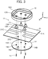
FIG. 3 is an exploded perspective view of the connector according toEmbodiment 1 when viewed from obliquely above. -
FIG. 4 is an exploded perspective view of the connector according toEmbodiment 1 when viewed from obliquely below. -
FIG. 5 is a perspective cross-sectional view showing a contact used in the connector according toEmbodiment 1. -
FIG. 6 is a perspective view showing a projection used in the connector according toEmbodiment 1. -
FIG. 7 is a perspective view showing a blade member used in the connector according toEmbodiment 1. -
FIG. 8 is a perspective view showing the blade member fixed in the projection. -
FIG. 9 is a perspective view showing a state where a flexible substrate is being cut with the blade member inEmbodiment 1. -
FIG. 10 is a perspective view showing the projection and the blade member that project from the flexible substrate. -
FIG. 11 is a plan view showing the projection and the blade member that project from the flexible substrate. -
FIG. 12 is a cross-sectional view taken along line A-A inFIG. 2 . -
FIG. 13 is a cross-sectional view taken along line B-B inFIG. 2 . -
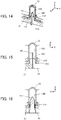
FIG. 14 is a cutaway perspective view showing a main part of the connector according toEmbodiment 1. -
FIG. 15 is an enlarged view of a main part ofFIG. 12 . -
FIG. 16 is an enlarged view of a main part ofFIG. 13 . -
FIG. 17 is a perspective view of the connector according toEmbodiment 1 and a counter connector in a non-fitted state when viewed from obliquely above. -
FIG. 18 is a perspective view of the connector according toEmbodiment 1 and the counter connector in the non-fitted state when viewed from obliquely below. -
FIG. 19 is an exploded cutaway perspective view of a connector according toEmbodiment 2. -
FIG. 20 is a plan view showing a projection and a blade member that project from a flexible substrate inEmbodiment 3. -
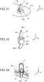
FIG. 21 is a perspective view showing a state where the projection projects through a cut flexible substrate inEmbodiment 3. -
FIG. 22 is a perspective view showing a blade member used in a connector according toEmbodiment 4. -
FIG. 23 is a cutaway perspective view showing a main part of the connector according to Embodiment 4. -
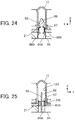
FIG. 24 is a cross-sectional view showing the main part of the connector according to Embodiment 4. -
FIG. 25 is a cross-sectional view showing the main part of the connector according to Embodiment 4. -
FIG. 26 is an exploded cutaway perspective view of a connector according toEmbodiment 5. -
FIG. 27 is a cross-sectional view showing a main part of the connector according to Embodiment 5. -
FIG. 28 is a cross-sectional view showing the main part of the connector according toEmbodiment 5. -
FIG. 29 is an exploded cutaway perspective view of a connector according toEmbodiment 6. -
FIG. 30 is a cutaway perspective view showing a main part of the connector according to Embodiment 6. -
FIG. 31 is a cross-sectional front view showing the connector according toEmbodiment 6. -
FIG. 32 is a cross-sectional side view showing the connector according toEmbodiment 6. -
FIG. 33 is an exploded cutaway perspective view of a connector according toEmbodiment 7. -
FIG. 34 is a cutaway perspective view showing a main part of the connector according to Embodiment 7. -
FIG. 35 is a cross-sectional front view showing the connector according toEmbodiment 7. -
FIG. 36 is a cross-sectional side view showing the connector according toEmbodiment 7. -
FIG. 37 is a partial cross-sectional view showing a conventional connector mounted on a flat cable. - Embodiments of the present invention are described below based on the appended drawings.
-
FIGS. 1 and 2 show aconnector 11 according toEmbodiment 1. Theconnector 11 is used as, for example, a garment-side connector part used for fitting a wearable device and is mounted on aflexible substrate 21. - The
connector 11 includes ahousing 12 disposed on theflexible substrate 21, and fourcontacts 13. Thehousing 12 has arecess 12A. The fourcontacts 13 project perpendicularly to theflexible substrate 21 within therecess 12A of thehousing 12. - For convenience, the
flexible substrate 21 is defined as extending along an XY plane, and the direction in which thecontacts 13 project is referred to as "+Z direction." - As shown in
FIGS. 3 and4 , theconnector 11 further includes abase member 14 disposed on the -Z direction side of theflexible substrate 21 and is mounted on theflexible substrate 21 as sandwiching theflexible substrate 21 between thehousing 12 and thebase member 14. - The
flexible substrate 21 has atop surface 21A facing in the +Z direction and abottom surface 21B facing in the -Z direction, and fourflexible conductors 21C serving as conductive portions are exposed on thetop surface 21A. The fourflexible conductors 21C correspond to the fourcontacts 13 and each take on a strip shape extending in the Y direction. - The
flexible substrate 21 is further provided with two through-holes 21D. - The
housing 12 is made of an insulating material such as an insulating resin and is provided with four contact through-holes 12B in therecess 12A opening in the +Z direction. The four contact through-holes 12B separately correspond to the fourcontacts 13. Two recessedpost accommodating portions 12D are formed at positions outside therecess 12A in the X direction and the Y direction and on a -Z direction-side surface 12C of thehousing 12. - Each of the four
contacts 13 is a plug-type contact made of a conductive material such as a metal and has atubular portion 13A having a cylindrical shape extending in the Z direction and aflange 13B extending from a -Z directional end of thetubular portion 13A along an XY plane. Theflange 13B has asecond surface 13C facing in the -Z direction. - The
base member 14 is made of an insulating material such as an insulating resin and has aflat plate portion 14A. Theflat plate portion 14A has afirst surface 14B facing in the +Z direction. Fourprojections 14C project on thefirst surface 14B. In addition, two housing fixing posts 14D project on thefirst surface 14B of theflat plate portion 14A. - The
base member 14 is further provided with fourslits 14F that separately extend from asurface 14E, facing in the -Z direction, of theflat plate portion 14A and penetrate the fourprojections 14C in the Z direction. - The
connector 11 further includes fourblade members 15 separately inserted in the fourslits 14F of thebase member 14. - As shown in
FIGS. 3 and4 , the four contact through-holes 12B of thehousing 12, the fourflexible conductors 21C of theflexible substrate 21 and the fourprojections 14C of thebase member 14 are arranged to correspond to each other in position. - Similarly, the two
post accommodating portions 12D of thehousing 12, the two through-holes 21D of theflexible substrate 21 and the two housing fixing posts 14D of thebase member 14 are arranged to correspond to each other in position. - The through-
holes 21D of theflexible substrate 21 have an inside diameter slightly larger than the outside diameter of thehousing fixing posts 14D of thebase member 14 to allow smooth insertion of the housing fixing posts 14D. Further, thepost accommodating portions 12D of thehousing 12 have an inside diameter slightly smaller than the outside diameter of thehousing fixing posts 14D of thebase member 14, and by press-fitting the housing fixing posts 14D into thepost accommodating portions 12D, thehousing 12 and thebase member 14 are fixed to each other. - The contact through-
holes 12B of thehousing 12 have an inside diameter larger than the outside diameter of thetubular portions 13A of thecontacts 13 and smaller than the outside diameter of theflanges 13B to allow smooth insertion of thetubular portions 13A of thecontacts 13. - As shown in
FIG. 5 , thetubular portion 13A of thecontact 13 has a cylindrical shape with its +Z directional end being closed, theflange 13B is formed integrally with the -Z directional end of thetubular portion 13A, and aprojection accommodating portion 13D of recess shape is provided in thesecond surface 13C of theflange 13B facing in the -Z direction. Specifically, theprojection accommodating portion 13D is formed inside thetubular portion 13A so as to have an opening end at thesecond surface 13C of theflange 13B. - The
projection accommodating portion 13D of thecontact 13 has an inside diameter smaller than a value obtained by adding a double of the sum of the thickness of theflexible substrate 21 at the portion where theflexible conductor 21C is exposed and the thickness of theflexible conductor 21C to the outside diameter of theprojection 14C of thebase member 14. Thecontact 13 as above can be manufactured by, for example, stamping a metal plate. - As shown in
FIG. 6 , theprojection 14C of thebase member 14 has a columnar shape extending in the Z direction and hasouter surfaces 14G extending parallel to the direction in which theprojection 14C projects. Theprojection 14C is divided into two parts, a +Y directional part and a -Y directional part, by theslit 14F formed along an XZ plane passing the central axis of the columnar shape. - As shown in
FIG. 7 , theblade member 15 is a flat plate member made of a metal material and extending along an XZ plane. Theblade member 15 has, at its +Z directional end, apointed portion 15A that is pointed in the +Z direction and also has, near its -Z directional end, a pair ofprotrusions 15B separately protruding in the +X and -X directions. The size of theblade member 15 in the Z direction is set to be larger than the total size, in the Z direction, of theflat plate portion 14A and theprojection 14C of thebase member 14. The pointedportion 15A is formed to be narrower in width in the X and Y directions as advancing in the +Z direction. - Before the operation of mounting the
connector 11 to theflexible substrate 21, the fourblade members 15 are attached to thebase member 14. As shown inFIG. 4 , theblade members 15 are inserted into theslits 14F opening at thesurface 14E, facing in the -Z direction, of theflat plate portion 14A of thebase member 14 from the -Z direction side. When theblade member 15 is inserted in theslit 14F up to the position where the -Z directional end of theblade member 15 is situated on thesurface 14E, facing in the -Z direction, of theflat plate portion 14A of thebase member 14, the pointedportion 15A of theblade member 15 projects from theprojection 14C of thebase member 14 in the +Z direction as shown inFIG. 8 . In addition, the pair ofprotrusions 15B of theblade member 15 are press-fitted into theslit 14F, so that theblade member 15 is fixed relative to theprojection 14C of thebase member 14. - Note that the
housing fixing posts 14D formed on theflat plate portion 14A of thebase member 14 are higher than the pointedportions 15A of theblade members 15 projecting from theprojections 14C in the +Z direction. - In mounting the
connector 11 onto theflexible substrate 21, first, inFIGS. 3 and4 , the two housing fixing posts 14D of thebase member 14 are separately inserted into the two through-holes 21D so as to project above thetop surface 21A of theflexible substrate 21, thetubular portions 13A of the fourcontacts 13 are separately inserted into the four contact through-holes 12B of thehousing 12 from the -Z direction side, and the tips of the two housing fixing posts 14D of thebase member 14 projecting above thetop surface 21A of theflexible substrate 21 are separately inserted into the twopost accommodating portions 12D of thehousing 12. As a result, thehousing 12, the fourcontacts 13, theflexible substrate 21 and thebase member 14 are aligned with each other in the X direction and the Y direction. - Since the
housing fixing posts 14D of thebase member 14 is higher than theblade members 15 projecting from theprojections 14C, the housing fixing posts 14D are inserted into the through-holes 21D of theflexible substrate 21 without being affected by the presence of theprojections 14C and theblade members 15. - In this state, when the
housing 12 and thebase member 14 are pressed in the Z direction so that they come close to each other, the -Z direction-side surface 12C of thehousing 12 and thesecond surfaces 13C of the fourcontacts 13 facing in the -Z direction come into contact with thetop surface 21A of theflexible substrate 21, and thepointed portions 15A of theblade members 15 projecting from the fourprojections 14C of thebase member 14 in the +Z direction come into contact with thebottom surface 21B of theflexible substrate 21 such that the contacted portions of theflexible substrate 21 are pressed toward the inside of theprojection accommodating portions 13D of thecontacts 13 in the +Z direction. - As a result, the
flexible substrate 21 and theflexible conductors 21C positioned on the +Z direction side of theprojections 14C in a corresponding manner to theprojections 14C are cut with the pointedportions 15A of theblade members 15 extending along an XZ plane as shown inFIG. 9 , and then, as shown inFIG. 10 , theprojections 14C project on the +Z direction side of theflexible conductors 21C through the cut portions. Consequently, cut-end-portions 21E of theflexible substrate 21 are made to extend along theouter surfaces 14G of eachprojection 14 on the +Y and -Y direction sides. - As shown in
FIG. 11 , the width W1 of theblade member 15 in the X direction is defined to be smaller than the width W2 of theflexible conductor 21C in the X direction. Since theblade member 15 is inserted in theslit 14F penetrating theprojection 14C in the Z direction, the size D2 of theprojection 14C in the Y direction that is the thickness direction of theblade member 15 is larger than the thickness D1 of theblade member 15. - When the
housing 12 and thebase member 14 are further moved in the Z direction so that they come close to each other, as shown inFIGS. 12 and 13 , theprojections 14C of thebase member 14 and theblade members 15 are inserted into the insides of the correspondingcontacts 13, which allows thefirst surface 14B of thebase member 14 facing in the +Z direction to come into contact with thebottom surface 21B of theflexible substrate 21. - Since the contact through-
holes 12B of thehousing 12 have an inside diameter larger than the outside diameter of thetubular portions 13A of thecontacts 13 and smaller than the outside diameter of theflanges 13B, theflange 13B of eachcontact 13 is sandwiched between the -Z direction-side surface 12C of thehousing 12 and thetop surface 21A of theflexible substrate 21, whereby thecontacts 13 are fixed relative to thebase member 14. Further, thehousing 12 and thebase member 14 are fixed to each other by press-fitting the two housing fixing posts 14D of thebase member 14 into the twopost accommodating portions 12D of thehousing 12, and thus the mounting of theconnector 11 onto theflexible substrate 21 is completed. - At this time, since, as shown in
FIG. 10 , the cut-end-portions 21E of theflexible substrate 21 extend in the +Z direction along theouter surfaces 14G of theprojection 14, as shown inFIGS. 14 to 16 , theprojection 14C is inserted into theprojection accommodating portion 13D with the cut-end-portions 21E of theflexible substrate 21 being sandwiched between theouter surfaces 14G of theprojection 14C and the inner surface of theprojection accommodating portion 13D. Accordingly, the inner surface of theprojection accommodation portion 13D of thecontact 13 comes into contact with theflexible conductor 21C at the cut-end-portions 21E. - As described above, the
projection accommodating portion 13D of thecontact 13 has an inside diameter smaller than a value obtained by adding a double of the sum of the thickness of theflexible substrate 21 at the portion where theflexible conductor 21C is exposed and the thickness of theflexible conductor 21C to the outside diameter of theprojection 14C of thebase member 14, and therefore, theflexible conductor 21C at the cut-end-portions 21E is pressed by theprojection 14C against the inner surface of theprojection accommodating portion 13D of thecontact 13 such that a contact pressure is applied thereto, whereby thecontact 13 is electrically connected to theflexible conductor 21C. - Thus, the
flexible substrate 21 and theflexible conductor 21C are cut by means of theblade member 15 fixed relative to theprojection 14C of thebase member 14, and the cut-end-portions 21E of theflexible substrate 21 are sandwiched between theouter surfaces 14G of theprojection 14C and theprojection accommodating portion 13D of thecontact 13. Owing to this configuration, even when theflexible substrate 21 is made of a material that is not so elastically stretchable, thecontact 13 can be electrically connected to theflexible conductor 21C of theflexible substrate 21 without fail. - In addition, the
connector 11 can be easily mounted on theflexible substrate 21 merely by moving thehousing 12 and thebase member 14 so that they come close to each other as sandwiching theflexible substrate 21 therebetween. - In addition, since the
base member 14 includes the twohousing fixing posts 14D that are higher than the pointedportions 15A of theblade members 15 projecting from theprojections 14C of thebase member 14 in the +Z direction, by inserting thosehousing fixing posts 14D separately into the two through-holes 21D of theflexible substrate 21 and then the twopost accommodating portions 12D of thehousing 12, thehousing 12, the fourcontacts 13, theflexible substrate 21 and thebase member 14 can be aligned with each other in the X direction and the Y direction while their shifting is limited, thereby further facilitating the mounting work of theconnector 11 onto theflexible substrate 21. - While the four
contacts 13 are used, it suffices if the connector has at least onecontact 13. Regardless of the number of thecontacts 13, all of thecontacts 13 can be simultaneously fitted into the correspondingprojections 14C of thebase member 14 by pressing thehousing 12 and thebase member 14 so that they come close to each other as sandwiching theflexible substrate 21 therebetween, and therefore, even when theconnector 11 is a multi-contact connector having a plurality ofcontacts 13, it is possible to achieve easy mounting and reliable electrical connection. - While the
contact 13 is fixed relative to thebase member 14 by sandwiching theflange 13B of thecontact 13 between thehousing 12 and thebase member 14, the invention is not limited thereto, and thecontact 13 may be fixed to thebase member 14 by any of other known methods such as screwing and press-fitting. - While the
housing 12 and thebase member 14 are mutually fixed by press-fitting thehousing fixing posts 14D of thebase member 14 into thepost accommodating portions 12D of thehousing 12, this assembling technique is merely an example, and the invention is not limited thereto. For example, thehousing 12 can be fixed to thebase member 14 by any of other methods such as screwing and adhering. - Since the
base member 14 does not come into direct contact with thecontacts 13 or theflexible conductors 21C of theflexible substrate 21, thebase member 14 may be made of a conductive material such as metal instead of an insulating material. - For the
flexible substrate 21 on which theconnector 11 is mounted, use is made of a flexible substrate having thetop surface 21A on which theflexible conductors 21C serving as conductive portions are exposed and thebottom surface 21B on which no conductive portion is exposed; however, the invention is not limited thereto, and it suffices if a flexible substrate for use is configured such that a conductive portion is exposed at least on its top surface. Accordingly, a fabric having a top surface coated with a conductive layer, a fabric in which conductive fibers are woven, and other fabrics may be used as a flexible substrate on which theconnector 11 is mounted. - While the
outer surfaces 14G of theprojection 14C of thebase member 14 extend parallel to the direction in which theprojection 14C projects, the invention is not limited thereto, and theprojection 14C may taper in the +Z direction to a certain extent as long as theprojection accommodating portion 13D has an inside diameter smaller than a value obtained by adding a double of the sum of the thickness of theflexible substrate 21 at the portion where theflexible conductor 21C is exposed and the thickness of theflexible conductor 21C to the outside diameter of theprojection 14C of thebase member 14. -
FIGS. 17 and 18 show the state where theconnector 11 mounted on theflexible substrate 21 is aligned with anelectronic device module 31 which is a counter connector. - The
electronic device module 31 has ahousing 32 made of an insulating material such as an insulating resin, and fourcontacts 33 disposed inside thehousing 32. Thecontacts 33 are each a contact having a spring contact point. - The
housing 32 has a raisedportion 32A protruding in the -Z direction, and fouropenings 32B corresponding to the fourcontacts 33 are formed in the raisedportion 32A. The fourcontacts 33 are exposed through the correspondingopenings 32B of thehousing 32. - The raised
portion 32A of thehousing 32 and the fourcontacts 33 are arranged so as to respectively correspond to therecess 12A of thehousing 12 and the fourcontacts 13 in theconnector 11 in position in an XY plane, and the raisedportion 32A of thehousing 32 has a shape and size allowing its insertion into therecess 12A of thehousing 12 of theconnector 11. - By fitting the
electronic device module 31 as above into theconnector 11, each of the fourcontacts 13 of theconnector 11 is electrically connected to thecorresponding contact 33 of theelectronic device module 31. - When the
connector 11 is configured as a garment-side connector part to be attached to a garment, theelectronic device module 31 is usable as a wearable device to be connected to the garment-side connector part. - In
Embodiment 1, while theflexible substrate 21 has theflexible conductors 21C of strip shape extending in the Y direction, theblade members 15 have a flat plate shape extending along an XZ plane; however, the invention is not limited thereto. For instance, while theflexible conductors 21C have a strip shape extending in the Y direction, theblade members 15 may have a flat plate shape extending along a YZ plane, as in aconnector 41 shown inFIG. 19 . In this case, it is necessary to use, instead of thebase member 14 used inEmbodiment 1, abase member 44 in which slits 44F extending along a YZ plane according to the orientation of theblade members 15 are formed in aflat plate portion 44A andprojections 44C. - Since the direction in which the
blade member 15 extends and the direction in which theflexible conductor 21C extends are made the same, theflexible conductor 21C is to be cut with theblade member 15 in a direction in which theflexible conductor 21C extends. Therefore, even when theblade member 15 and theflexible conductor 21C are displaced relative to each other due to the given assembly tolerance or another reason, or even when the width W2 of theflexible conductor 21C shown inFIG. 11 is narrower, a cut portion can be placed within theflexible conductor 21C, establishing the electrical connection between thecontact 13 and theflexible conductor 21C without fail. - Thus, even when many
flexible conductors 21C are densely disposed on theflexible substrate 21 and the width W2 of eachflexible conductor 21C is narrower accordingly, it is possible to construct areliable connector 41. - While, in
Embodiment 1, theprojection 14C of thebase member 14 has a cylindrical shape extending in the Z direction, the invention is not limited thereto. As shown inFIG. 20 , use may be made of a projection having a columnar shape with a rectangular, for example, rhombus cross section in an XY plane. Also in this case, as shown inFIG. 21 , theflexible substrate 21 and theflexible conductor 21C are cut with theblade member 15 fixed relative to aprojection 54C, and theprojection 54C is made to project on the +Z direction side of theflexible conductor 21C. Consequently, the state where the cut-end-portions 21E of theflexible substrate 21 extend in the +Z direction alongouter surfaces 54G of the projection 54 can be established. - The
projection 54C has a size in the Y direction that is the thickness direction of theblade member 15 larger than the thickness of theblade member 15. - Thus, as with
Embodiment 1, a connector having excellent reliability in electrical connection with theflexible conductor 21C of theflexible substrate 21 can be obtained. - It is preferable for the
projection 54C to have the shape of rectangle with rounded corners in an XY plane, as shown inFIG. 20 . This is because the contact area between the cut-end-portions 21E of theflexible substrate 21 pressed by theprojection 54C against the inner surface of theprojection accommodating portion 13D of thecontact 13 and the inner surface of theprojection accommodating portion 13D becomes larger, which leads to smaller contact resistance between theflexible conductor 21C and thecontact 13. - While, in
Embodiment 1, theprojection 14C is formed at thebase member 14, ablade member 65 that is made of metal and obtained by integrally forming ablade portion 66 and aprojection 67 as shown inFIG. 22 may be used. - The
blade portion 66 has a flat plate shape extending along an XZ plane and includes a pointedportion 66A and a pair ofprotrusions 66B, as with theblade member 15 inEmbodiment 1. Theprojection 67 is obtained by curving a pair of arm portions separately extending from the +X and -X directional ends of theblade portion 66 and hasouter surfaces 67A together forming a cylindrical shape extending in the Z direction. Theblade member 65 as above can be formed by bending a single metal sheet. - The
projection 67 has a size in the Y direction that is the thickness direction of theblade portion 66 larger than the thickness of theblade portion 66. - As shown in
FIGS. 23 and24 , abase member 64 used inEmbodiment 4 has, instead of theprojection 14C, a through-hole 64A penetrating in the Z direction, and theblade member 65 is fixed relative to thebase member 64 when theblade member 65 is passed through the through-hole 64A and the pair ofprotrusions 66B of theblade portion 66 are press-fitted into the through-hole 64A. - The
projection accommodating portion 13D of thecontact 13 has an inside diameter smaller than a value obtained by adding a double of the sum of the thickness of theflexible substrate 21 at the portion where theflexible conductor 21C is exposed and the thickness of theflexible conductor 21C to the outside diameter of theprojection 67 of theblade member 65. - When the
housing 12 and thebase member 64 are moved so that they come close to each other as sandwiching theflexible substrate 21 therebetween, theblade portion 66 of theblade member 65 cuts theflexible substrate 21 and theflexible conductor 21C, and the cut-end-portions 21E of theflexible substrate 21 are sandwiched between theouter surfaces 67A of theprojection 67 and theprojection accommodating portion 13D of thecontact 13 as shown inFIG. 25 . - As described above, the
projection accommodating portion 13D of thecontact 13 has an inside diameter smaller than a value obtained by adding a double of the sum of the thickness of theflexible substrate 21 at the portion where theflexible conductor 21C is exposed and the thickness of theflexible conductor 21C to the outside diameter of theprojection 67 of theblade member 65, and accordingly, theflexible conductor 21C at the cut-end-portions 21E is pressed by theprojection 67 against the inner surface of theprojection accommodating portion 13D of thecontact 13 such that a contact pressure is applied thereto, whereby thecontact 13 is electrically connected to theflexible conductor 21C. - Thus, as with
Embodiment 1, a connector having excellent reliability in electrical connection with theflexible conductor 21C of theflexible substrate 21 can be obtained. - While, in
Embodiment 1, theblade members 15 are fixed relative to theprojections 14C of thebase member 14, as shown inFIGS. 26 to 28 , a connector may be configured such thatb4lade members 75 are fixed tocontacts 73. - As with the
contacts 13 inEmbodiment 1, eachcontact 73 has atubular portion 73A of cylindrical shape extending in the Z direction and aflange 73B extending from a -Z directional end of thetubular portion 73A along an XY plane. Thetubular portion 73A is provided with a pair ofattachment holes 73C separately facing in the +X and -X directions. - The
blade member 75 is a flat plate member made of a metal material and extending along an XZ plane, as with theblade member 15 inEmbodiment 1. However, theblade member 75 has, at its -Z directional end, apointed portion 75A that is pointed in the -Z direction and also has, near its +Z directional end, a pair ofprotrusions 75B separately protruding in the +X and -X directions in an opposite manner to theblade member 15 inEmbodiment 1. The pair ofprotrusions 75B of theblade member 75 are fitted into the pair ofattachment holes 73C of thecontact 73, whereby theblade member 75 is fixed to the inside of aprojection accommodating portion 73D of thecontact 73. - A
base member 74 used inEmbodiment 5 hasprojections 74C of columnar shape extending in the Z direction and is provided with blademember accommodating grooves 74A each extending along an XZ plane passing through the central axis of thecorresponding projection 74C. The pointedportion 75A is situated inside theprojection accommodating portion 73D. - The
projection 74C has a size in the Y direction that is the thickness direction of theblade member 75 larger than the thickness of theblade member 75. - The
projection accommodating portion 73D of thecontact 73 has an inside diameter smaller than a value obtained by adding a double of the sum of the thickness of theflexible substrate 21 at the portion where theflexible conductor 21C is exposed and the thickness of theflexible conductor 21C to the outside diameter of theprojection 74C of thebase member 74. - When the
housing 12 and thebase member 74 are moved so that they come close to each other as sandwiching theflexible substrate 21 therebetween, theblade member 75 cuts theflexible substrate 21 and theflexible conductor 21C at positions corresponding to theprojections 74C of thebase member 74. The cut-end-portions 21E of theflexible substrate 21 are sandwiched between the outer surfaces of theprojection 74C of thebase member 74 and the inner surface of theprojection accommodating portion 73D of thecontact 73. - As described above, the
projection accommodating portion 73D of thecontact 73 has an inside diameter smaller than a value obtained by adding a double of the sum of the thickness of theflexible substrate 21 at the portion where theflexible conductor 21C is exposed and the thickness of theflexible conductor 21C to the outside diameter of theprojection 74C of thebase member 74, and accordingly, theflexible conductor 21C at the cut-end-portions 21E is pressed by theprojection 74C against the inner surface of theprojection accommodating portion 73D of thecontact 73 such that a contact pressure is applied thereto, whereby thecontact 73 is electrically connected to theflexible conductor 21C. - Thus, as with
Embodiment 1, a connector having excellent reliability in electrical connection with theflexible conductor 21C of theflexible substrate 21 can be obtained. In addition, since theblade member 75 including the pointedportion 75A is accommodated in theprojection accommodating portion 73D of thecontact 73, the operation of mounting the connector to theflexible substrate 21 can be safely carried out. The pointedportion 75A may be disposed so as to project from theprojection accommodating portion 73D in a direction toward theflexible substrate 21. - As shown in
FIG. 27 , the pointedportion 75A of theblade member 75 that has cut theflexible substrate 21 and theflexible conductor 21C is accommodated within the blademember accommodating groove 74A of theprojection 74C. - In
Embodiment 1, theprojections 14C of thebase member 14 are inserted in theprojection accommodating portions 13D of thecontacts 13; however, another configuration may be employed in which, as shown inFIG. 29 , ahousing 82 is provided withprojections 82C while abase member 84 is provided withprojection accommodating portions 84A of recess shape, and theprojections 82C are inserted into theprojection accommodating portions 84A. - The
projections 82C of thehousing 82 are disposed near contact through-holes 82B and each have a columnar shape projecting in the -Z direction. Blademember accommodating grooves 82D are formed at thehousing 82 so as to each extend along an XZ plane passing through the central axis of thecorresponding projection 82C. - Each
projection accommodating portion 84A of thebase member 84 opens toward the +Z direction and has aslit 84B penetrating the bottom of theprojection accommodating portion 84A in the Z direction. Theblade member 15 is press-fitted into theslit 84B from the -Z direction side and thereby fixed to theprojection accommodating portion 84A of thebase member 84. - The
projection 82C of thehousing 82 has a size in the Y direction that is the thickness direction of theblade member 15 larger than the thickness of theblade member 15. - In
Embodiment 6,contact members 86 are used. Thecontact members 86 each have acontact 83 and a flexiblesubstrate connection portion 87 integrally connected to thecontact 83. As with thecontact 13 inEmbodiment 1, thecontact 83 has atubular portion 83A of cylindrical shape extending in the Z direction and aflange 83B extending from a -Z directional end of thetubular portion 83A along an XY plane. The flexiblesubstrate connection portion 87 is connected to an edge of theflange 83B of thecontact 83 and bends from the edge of theflange 83B to extend in the -Z direction. - The
contact member 86 is configured such that, when thetubular portion 83A of thecontact 83 is inserted in the contact through-hole 82B of thehousing 82, the flexiblesubstrate connection portion 87 extends in the -Z direction along the outer surfaces of theprojection 82C of thehousing 82. - The projection
accommodating portion 84A of thebase member 84 has an inside diameter smaller than a value obtained by adding: the outside diameter of theprojection 82C of thehousing 82; a double of the sum of the thickness of theflexible substrate 21 at the portion where theflexible conductor 21C is exposed and the thickness of theflexible conductor 21C; and the thickness of the flexiblesubstrate connection portion 87. - When the
housing 82 and thebase member 84 are moved so that they come close to each other as sandwiching theflexible substrate 21 therebetween, as shown inFIGS. 30 to 32 , theprojection 82C of thehousing 82 is inserted into theprojection accommodating portion 84A of thebase member 84, and theflexible substrate 21 and theflexible conductor 21C are cut with theblade member 15 fixed inside theprojection accommodating portion 84A. At this time, since the flexiblesubstrate connection portion 87 of thecontact member 86 lies along the outer surfaces of theprojection 82C of thehousing 82, the cut-end-portions 21E of theflexible substrate 21 and the flexiblesubstrate connection portion 87 of thecontact member 86 are sandwiched between the outer surfaces of theprojection 82C of thehousing 82 and the inner surface of theprojection accommodating portion 84A of thebase member 84, and theflexible conductor 21C of theflexible substrate 21 comes into contact with the flexiblesubstrate connection portion 87 of thecontact member 86. - As described above, the
projection accommodating portion 84A of thebase member 84 has an inside diameter smaller than a value obtained by adding: the outside diameter of theprojection 82C of thehousing 82; a double of the sum of the thickness of theflexible substrate 21 at the portion where theflexible conductor 21C is exposed and the thickness of theflexible conductor 21C; and the thickness of the flexiblesubstrate connection portion 87. Accordingly, theflexible conductor 21C at the cut-end-portions 21E is pressed by theprojection 82C against a surface of the flexiblesubstrate connection portion 87 such that a contact pressure is applied thereto, whereby thecontact member 86 is electrically connected to theflexible conductor 21C. - Thus, as with
Embodiment 1, a connector having excellent reliability in electrical connection with theflexible conductor 21C of theflexible substrate 21 can be obtained. - As shown in
FIG. 30 , the pointedportion 15A of theblade member 15 that has cut theflexible substrate 21 and theflexible conductor 21C is accommodated within the blademember accommodating groove 82D of thehousing 82. - While, in
Embodiment 6, theblade member 15 used to cut theflexible substrate 21 and theflexible conductor 21C is fixed inside theprojection accommodating portion 84A of thebase member 84, the invention is not limited thereto, and as shown inFIG. 33 , the connector may be configured such that acontact member 96 has ablade member 95. - The
housing 82 is identical to thehousing 82 used inEmbodiment 6. Specifically, theprojections 82C of columnar shape projecting in the -Z direction are formed near the contact through-holes 82B, and the blademember accommodating grooves 82D are formed at thehousing 82 so as to each extend along an XZ plane passing through the central axis of thecorresponding projection 82C. - The
projection 82C of thehousing 82 has a size in the Y direction that is the thickness direction of theblade member 95 larger than the thickness of theblade member 95. - The
contact member 96 has acontact 93, a flexiblesubstrate connection portion 97 connected to thecontact 93, and theblade member 95 connected to the flexiblesubstrate connection portion 97. As with thecontact 83 inEmbodiment 6, thecontact 93 has atubular portion 93A of cylindrical shape extending in the Z direction and aflange 93B extending from a -Z directional end of thetubular portion 93A along an XY plane. As with the flexiblesubstrate connection portion 87 inEmbodiment 6, the flexiblesubstrate connection portion 97 is connected to an edge of theflange 93B of thecontact 93 and bends from the edge of theflange 93B to extend in the -Z direction. Theblade member 95 is connected to a -Z directional end of the flexiblesubstrate connection portion 97, has a flat plate shape extending along an XZ plane, and is disposed such that itspointed portion 95A faces in the -Z direction. - As with the
contact member 86 inEmbodiment 6, thecontact member 96 is configured such that, when thetubular portion 93A of thecontact 93 is inserted in the contact through-hole 82B of thehousing 82, the flexiblesubstrate connection portion 97 extends in the -Z direction along the outer surfaces of theprojection 82C of thehousing 82. - The
base member 94 used inEmbodiment 7 has projectionaccommodating portions 94A of recess shape opening in the +Z direction, and the bottom of eachprojection accommodating portion 94A is provided with a blademember accommodating groove 94B penetrating in the Z direction along an XZ plane. - The projection
accommodating portion 94A of thebase member 94 has an inside diameter smaller than a value obtained by adding: the outside diameter of theprojection 82C of thehousing 82; a double of the sum of the thickness of theflexible substrate 21 at the portion where theflexible conductor 21C is exposed and the thickness of theflexible conductor 21C; and the thickness of the flexiblesubstrate connection portion 97. - When the
housing 82 and thebase member 94 are moved so that they come close to each other as sandwiching theflexible substrate 21 therebetween, as shown inFIGS. 34 to 36 , a +Z direction-side portion of theblade member 95 of thecontact member 96 is accommodated in the blademember accommodating groove 82D of theprojection 82C of thehousing 82 while the pointedportion 95A of theblade member 95 facing in the -Z direction cuts theflexible substrate 21 and theflexible conductor 21C, and then theprojection 82C of thehousing 82 is inserted into theprojection accommodating portion 94A of thebase member 94. At this time, since the flexiblesubstrate connection portion 97 of thecontact member 96 lies along the outer surfaces of theprojection 82C of thehousing 82, the cut-end-portions 21E of theflexible substrate 21 and the flexiblesubstrate connection portion 97 of thecontact member 96 are sandwiched between the outer surfaces of theprojection 82C of thehousing 82 and the inner surface of theprojection accommodating portion 94A of thebase member 94, and theflexible conductor 21C of theflexible substrate 21 comes into contact with the flexiblesubstrate connection portion 97 of thecontact member 96. - As described above, the
projection accommodating portion 94A of thebase member 94 has an inside diameter smaller than a value obtained by adding: the outside diameter of theprojection 82C of thehousing 82; a double of the sum of the thickness of theflexible substrate 21 at the portion where theflexible conductor 21C is exposed and the thickness of theflexible conductor 21C; and the thickness of the flexiblesubstrate connection portion 97. Accordingly, theflexible conductor 21C at the cut-end-portions 21E is pressed by theprojection 82C against a surface of the flexiblesubstrate connection portion 97 such that a contact pressure is applied thereto, whereby thecontact member 96 is electrically connected to theflexible conductor 21C. - Thus, a connector having excellent reliability in electrical connection with the
flexible conductor 21C of theflexible substrate 21 can be obtained. - As shown in
FIG. 35 , the pointedportion 95A of theblade member 95 that has cut theflexible substrate 21 and theflexible conductor 21C is accommodated within the blademember accommodating groove 94B of thebase member 94. - While the
contacts Embodiments 1 to 7 above, the invention is not limited thereto, and a connector may be configured such that a receptacle-type contact is connected to theflexible conductor 21C of theflexible substrate 21 in the same manner.
Claims (15)
- A connector to be mounted on a flexible substrate (21) that has a top surface (21A) and a bottom surface (21B) facing in opposite directions to each other and has a conductive portion (21C) exposed at least on the top surface, the connector comprising:a base member (14, 44, 64, 74) having a first surface (14B) facing the bottom surface (21B) of the flexible substrate (21);a contact (13, 73) made of a conductive material and having a second surface (13C) facing the conductive portion exposed on the top surface (21A) of the flexible substrate (21);a projection (14C, 44C, 54C, 67, 74C) protrudingly formed at one of the base member and the contact;a projection accommodating portion (13D, 73D) of recess shape disposed at the other of the base member and the contact and configured to accommodate the projection as sandwiching the flexible substrate therebetween; anda blade member (15, 65, 75) configured to cut the flexible substrate at a position corresponding to the projection when the projection is accommodated in the projection accommodating portion with the flexible substrate being sandwiched therebetween,wherein the projection (14C, 44C, 54C, 67, 74C) has a size (D2) in a thickness direction of the blade member (15, 65, 75) larger than a thickness (D1) of the blade member, andwherein the first surface of the base member comes into contact with the bottom surface of the flexible substrate while the second surface of the contact comes into contact with the top surface of the flexible substrate, the contact (13, 73) is fixed to the base member (14, 44, 64, 74) with the projection (14C, 44C, 54C, 67, 74C) being accommodated in the projection accommodating portion (13D, 73D), and a cut-end-portion (21E) of the flexible substrate cut with the blade member (15, 65, 75) is sandwiched between an outer surface (14G, 54G, 67A) of the projection (14C, 44C, 54C, 67, 74C) and an inner surface of the projection accommodating portion (13D, 73D), whereby the conductive portion comes into contact with the contact, so that the contact (13, 73) is electrically connected to the conductive portion (21C).
- The connector according to claim 1,
wherein the projection (14C, 44C, 54C, 67, 74C) is protrudingly formed at the first surface (14B) of the base member (14, 44, 64, 74), and
wherein the projection accommodating portion (13D, 73D) is provided at the second surface (13C) of the contact (13, 73). - The connector according to claim 2,
wherein the blade member (15) is fixed to the projection (14C, 44C, 54C). - The connector according to claim 3,
wherein the base member (14, 44) and the projection (14C, 44C, 54C) are integrally formed from an insulating material, and
wherein the blade member (15) is made of a metal material and attached to the projection. - The connector according to claim 3,
wherein the base member (64) is made of an insulating material, and
wherein the projection (67) and the blade member (65) are integrally formed from a metal material and are attached to the base member. - The connector according to claim 2,
wherein the blade member (75) is made of a metal material and fixed to an inside of the projection accommodating portion (73D). - The connector according to claim 6,
wherein the projection (74C) has a blade member accommodating groove (74A) configured to accommodate the blade member (75) when the projection is accommodated in the projection accommodating portion (73D). - The connector according to any one of claims 1 to 7,
wherein the blade member (15, 65, 75) is smaller in width than the conductive portion (21C) of the flexible substrate (21). - The connector according to any one of claims 1 to 8,
wherein the outer surface (14G, 54G, 67A) of the projection (14C, 44C, 54C, 67, 74C) extends parallel to a direction in which the projection protrudes. - A connector to be mounted on a flexible substrate (21) that has a top surface (21A) and a bottom surface (21B) facing in opposite directions to each other and has a conductive portion (21C) exposed at least on the top surface, the connector comprising:a base member (84, 94) having a first surface facing the bottom surface (21B) of the flexible substrate (21);a contact (83, 93) made of a conductive material and having a second surface facing the conductive portion exposed on the top surface (21A) of the flexible substrate (21);a housing (82) to be fixed relative to the base member to thereby fix the contact to the base member;a projection (82C) formed at one of the base member and the housing;a projection accommodating portion (84A, 94A) of recess shape disposed at the other of the base member and the housing and configured to accommodate the projection as sandwiching the flexible substrate (21) therebetween; anda blade member (15, 95) configured to cut the flexible substrate at a position corresponding to the projection when the projection is accommodated in the projection accommodating portion with the flexible substrate being sandwiched therebetween,wherein the projection has a size in a thickness direction of the blade member larger than a thickness of the blade member,wherein the contact has a flexible substrate connection portion (87, 97) that is inserted into the projection accommodating portion when the contact is fixed to the base member by means of the housing, andwherein the first surface of the base member comes into contact with the bottom surface of the flexible substrate while the second surface of the contact comes into contact with the top surface of the flexible substrate, the housing is fixed to the base member with the projection being accommodated in the projection accommodating portion, and a cut-end-portion (21E) of the flexible substrate cut with the blade member and the flexible substrate connection portion (87, 97) of the contact are sandwiched between an outer surface of the projection (82C) and an inner surface of the projection accommodating portion (84A, 94A), whereby the conductive portion comes into contact with the flexible substrate connection portion of the contact, so that the contact (83, 93) is electrically connected to the conductive portion (21C).
- The connector according to claim 10,
wherein the base member (84) and the housing (82) are made of an insulating material, and
wherein the blade member (15) is made of a metal material and disposed in the projection accommodating portion (84A). - The connector according to claim 11,
wherein the projection (82C) has a blade member accommodating groove (82D) configured to accommodate the blade member (15) when the projection is accommodated in the projection accommodating portion (84A). - The connector according to claim 10,
wherein the base member (94) and the housing (82) are made of an insulating material, and
wherein the blade member (95) is made of a metal material and disposed at the projection (82C). - The connector according to any one of claims 10 to 13,
wherein the blade member (15, 95) is smaller in width than the conductive portion (21C) of the flexible substrate (21). - The connector according to any one of claims 10 to 14,
wherein the outer surface of the projection (82C) extends parallel to a direction in which the projection protrudes.
Applications Claiming Priority (1)
| Application Number | Priority Date | Filing Date | Title |
|---|---|---|---|
| JP2017053389A JP6792493B2 (en) | 2017-03-17 | 2017-03-17 | connector |
Publications (2)
| Publication Number | Publication Date |
|---|---|
| EP3376601A1 true EP3376601A1 (en) | 2018-09-19 |
| EP3376601B1 EP3376601B1 (en) | 2020-04-22 |
Family
ID=61007591
Family Applications (1)
| Application Number | Title | Priority Date | Filing Date |
|---|---|---|---|
| EP18152549.4A Active EP3376601B1 (en) | 2017-03-17 | 2018-01-19 | Connector |
Country Status (3)
| Country | Link |
|---|---|
| US (1) | US10096918B1 (en) |
| EP (1) | EP3376601B1 (en) |
| JP (1) | JP6792493B2 (en) |
Cited By (9)
| Publication number | Priority date | Publication date | Assignee | Title |
|---|---|---|---|---|
| EP3739690A1 (en) * | 2019-05-17 | 2020-11-18 | Japan Aviation Electronics Industry, Limited | Connecting method, connecting structure, contact and connector |
| US10868380B1 (en) | 2019-07-19 | 2020-12-15 | Japan Aviation Electronics Industry, Limited | Connector adapted to be connected to flexible conductor |
| US10886650B1 (en) | 2019-07-19 | 2021-01-05 | Japan Aviation Electronics Industry, Limited | Connector adapted to be connected to flexible conductor |
| EP4002597A1 (en) * | 2020-11-18 | 2022-05-25 | Japan Aviation Electronics Industry, Ltd. | Connector |
| CN117317656A (en) * | 2022-06-27 | 2023-12-29 | 日本航空电子工业株式会社 | Chip conductive components and connectors |
| EP4318813A1 (en) * | 2022-08-04 | 2024-02-07 | Japan Aviation Electronics Industry, Limited | Connector |
| EP4329104A1 (en) * | 2022-08-25 | 2024-02-28 | Japan Aviation Electronics Industry, Limited | Connector |
| EP4333215A1 (en) * | 2022-08-31 | 2024-03-06 | Japan Aviation Electronics Industry, Limited | Connector and connector assembly |
| EP4376224A1 (en) * | 2022-11-24 | 2024-05-29 | Japan Aviation Electronics Industry, Limited | Connector assembly |
Families Citing this family (11)
| Publication number | Priority date | Publication date | Assignee | Title |
|---|---|---|---|---|
| JP7178956B2 (en) | 2019-05-17 | 2022-11-28 | 日本航空電子工業株式会社 | Connection method, connection structure and connection terminal assembly |
| JP7313990B2 (en) * | 2019-09-09 | 2023-07-25 | 日本航空電子工業株式会社 | Connector and connection method |
| JP7313991B2 (en) * | 2019-09-09 | 2023-07-25 | 日本航空電子工業株式会社 | connector |
| JP7265458B2 (en) | 2019-09-26 | 2023-04-26 | 日本航空電子工業株式会社 | Connector and connection method |
| JP7348024B2 (en) * | 2019-10-24 | 2023-09-20 | 日本航空電子工業株式会社 | Connector and connection method |
| JP7558110B2 (en) * | 2021-04-26 | 2024-09-30 | 日本航空電子工業株式会社 | Connection method and connector assembly |
| JP7898340B2 (en) * | 2022-09-14 | 2026-07-31 | 日本航空電子工業株式会社 | connector |
| JP7822290B2 (en) * | 2022-09-28 | 2026-03-02 | 日本航空電子工業株式会社 | connector |
| JP2024065476A (en) * | 2022-10-31 | 2024-05-15 | 日本航空電子工業株式会社 | Connector and connector assembly |
| JP2024162643A (en) * | 2023-05-11 | 2024-11-21 | 日本航空電子工業株式会社 | connector |
| JP2025005598A (en) * | 2023-06-28 | 2025-01-17 | 日本航空電子工業株式会社 | Connector Assembly |
Citations (3)
| Publication number | Priority date | Publication date | Assignee | Title |
|---|---|---|---|---|
| US4526432A (en) * | 1979-12-26 | 1985-07-02 | Lockheed Corporation | Electrical connector assembly for flat cables |
| EP0261527A2 (en) * | 1986-09-25 | 1988-03-30 | Tektronix Inc. | Apparatus and method for producing a high density of electrical interconnections |
| JP2005063872A (en) | 2003-08-19 | 2005-03-10 | Furukawa Electric Co Ltd:The | Flat cable connection and connection structure |
Family Cites Families (7)
| Publication number | Priority date | Publication date | Assignee | Title |
|---|---|---|---|---|
| JPS5711339Y2 (en) * | 1976-09-09 | 1982-03-05 | ||
| JPS553880U (en) * | 1978-06-24 | 1980-01-11 | ||
| JP2595665Y2 (en) * | 1990-11-30 | 1999-05-31 | アイシン精機株式会社 | Connecting device for conductive cloth |
| JP6443609B2 (en) * | 2012-07-10 | 2018-12-26 | パナソニックIpマネジメント株式会社 | Connector device and female connector used therefor |
| JP5941010B2 (en) * | 2013-04-10 | 2016-06-29 | 日本電信電話株式会社 | Conductive fabric connector and method for producing conductive fabric connector |
| JP6199220B2 (en) * | 2014-03-26 | 2017-09-20 | 日本航空電子工業株式会社 | Thin connector |
| JP6513480B2 (en) * | 2015-05-22 | 2019-05-15 | 日本航空電子工業株式会社 | connector |
-
2017
- 2017-03-17 JP JP2017053389A patent/JP6792493B2/en active Active
-
2018
- 2018-01-15 US US15/871,405 patent/US10096918B1/en active Active
- 2018-01-19 EP EP18152549.4A patent/EP3376601B1/en active Active
Patent Citations (3)
| Publication number | Priority date | Publication date | Assignee | Title |
|---|---|---|---|---|
| US4526432A (en) * | 1979-12-26 | 1985-07-02 | Lockheed Corporation | Electrical connector assembly for flat cables |
| EP0261527A2 (en) * | 1986-09-25 | 1988-03-30 | Tektronix Inc. | Apparatus and method for producing a high density of electrical interconnections |
| JP2005063872A (en) | 2003-08-19 | 2005-03-10 | Furukawa Electric Co Ltd:The | Flat cable connection and connection structure |
Cited By (16)
| Publication number | Priority date | Publication date | Assignee | Title |
|---|---|---|---|---|
| EP3739690A1 (en) * | 2019-05-17 | 2020-11-18 | Japan Aviation Electronics Industry, Limited | Connecting method, connecting structure, contact and connector |
| US11398689B2 (en) | 2019-05-17 | 2022-07-26 | Japan Aviation Electronics Industry, Limited | Connecting method, connecting structure, contact and connector |
| US10868380B1 (en) | 2019-07-19 | 2020-12-15 | Japan Aviation Electronics Industry, Limited | Connector adapted to be connected to flexible conductor |
| US10886650B1 (en) | 2019-07-19 | 2021-01-05 | Japan Aviation Electronics Industry, Limited | Connector adapted to be connected to flexible conductor |
| EP3767754A1 (en) * | 2019-07-19 | 2021-01-20 | Japan Aviation Electronics Industry, Ltd. | Connector |
| EP3767753A1 (en) * | 2019-07-19 | 2021-01-20 | Japan Aviation Electronics Industry, Ltd. | Connector |
| EP4002597A1 (en) * | 2020-11-18 | 2022-05-25 | Japan Aviation Electronics Industry, Ltd. | Connector |
| US11658433B2 (en) | 2020-11-18 | 2023-05-23 | Japan Aviation Electronics Industry, Limited | Connector |
| CN117317656A (en) * | 2022-06-27 | 2023-12-29 | 日本航空电子工业株式会社 | Chip conductive components and connectors |
| EP4300713A1 (en) * | 2022-06-27 | 2024-01-03 | Japan Aviation Electronics Industry, Limited | Sheet type conductive member and connector |
| EP4318813A1 (en) * | 2022-08-04 | 2024-02-07 | Japan Aviation Electronics Industry, Limited | Connector |
| US12567691B2 (en) | 2022-08-04 | 2026-03-03 | Japan Aviation Electronics Industry, Limited | Connector |
| EP4329104A1 (en) * | 2022-08-25 | 2024-02-28 | Japan Aviation Electronics Industry, Limited | Connector |
| US12394931B2 (en) | 2022-08-25 | 2025-08-19 | Japan Aviation Electronics Industry, Limited | Connector |
| EP4333215A1 (en) * | 2022-08-31 | 2024-03-06 | Japan Aviation Electronics Industry, Limited | Connector and connector assembly |
| EP4376224A1 (en) * | 2022-11-24 | 2024-05-29 | Japan Aviation Electronics Industry, Limited | Connector assembly |
Also Published As
| Publication number | Publication date |
|---|---|
| JP6792493B2 (en) | 2020-11-25 |
| US20180269606A1 (en) | 2018-09-20 |
| US10096918B1 (en) | 2018-10-09 |
| EP3376601B1 (en) | 2020-04-22 |
| JP2018156861A (en) | 2018-10-04 |
Similar Documents
| Publication | Publication Date | Title |
|---|---|---|
| EP3376601B1 (en) | Connector | |
| EP3361575B1 (en) | Connector | |
| JP7232143B2 (en) | connector | |
| EP3800739A1 (en) | Connector and connecting method | |
| EP3435490B1 (en) | Connection assisting member and circuit board assembly | |
| CN112467466B (en) | Connector and connecting method | |
| EP3799217B1 (en) | Connector and connecting method | |
| CN112713425B (en) | Connector and connecting method | |
| EP3783742A1 (en) | Connector and connecting method | |
| EP3487008B1 (en) | Connector | |
| JP2024041400A (en) | connector | |
| EP3799218B1 (en) | Connector | |
| EP3696918B1 (en) | Connecting method, connecting structure and connection terminal | |
| US12230907B2 (en) | Electrical connector for connecting an electric wire to a flat flexible conductor and an electrical connector assembly therefor | |
| JP2024094608A (en) | Connectors and connection methods | |
| EP4462605B1 (en) | Connector | |
| JP7216556B2 (en) | Covered Conductor Connection Method, Covered Conductor Connection Structure, and Covered Conductor Connection Member | |
| CN115249923B (en) | Connection method and connector assembly | |
| JP2025132682A (en) | connector | |
| JP2002093490A (en) | Board connection connector | |
| JP2024078683A (en) | Connector assembly and connection method | |
| JP2024021591A (en) | connector | |
| EP4362233B1 (en) | Connector and connector assembly | |
| EP4343974A1 (en) | Connector | |
| EP4379964A1 (en) | Connector assembly and connecting method |
Legal Events
| Date | Code | Title | Description |
|---|---|---|---|
| PUAI | Public reference made under article 153(3) epc to a published international application that has entered the european phase |
Free format text: ORIGINAL CODE: 0009012 |
|
| STAA | Information on the status of an ep patent application or granted ep patent |
Free format text: STATUS: REQUEST FOR EXAMINATION WAS MADE |
|
| 17P | Request for examination filed |
Effective date: 20180119 |
|
| AK | Designated contracting states |
Kind code of ref document: A1 Designated state(s): AL AT BE BG CH CY CZ DE DK EE ES FI FR GB GR HR HU IE IS IT LI LT LU LV MC MK MT NL NO PL PT RO RS SE SI SK SM TR |
|
| AX | Request for extension of the european patent |
Extension state: BA ME |
|
| RBV | Designated contracting states (corrected) |
Designated state(s): AL AT BE BG CH CY CZ DE DK EE ES FI FR GB GR HR HU IE IS IT LI LT LU LV MC MK MT NL NO PL PT RO RS SE SI SK SM TR |
|
| STAA | Information on the status of an ep patent application or granted ep patent |
Free format text: STATUS: EXAMINATION IS IN PROGRESS |
|
| 17Q | First examination report despatched |
Effective date: 20190129 |
|
| GRAP | Despatch of communication of intention to grant a patent |
Free format text: ORIGINAL CODE: EPIDOSNIGR1 |
|
| STAA | Information on the status of an ep patent application or granted ep patent |
Free format text: STATUS: GRANT OF PATENT IS INTENDED |
|
| INTG | Intention to grant announced |
Effective date: 20190923 |
|
| GRAJ | Information related to disapproval of communication of intention to grant by the applicant or resumption of examination proceedings by the epo deleted |
Free format text: ORIGINAL CODE: EPIDOSDIGR1 |
|
| STAA | Information on the status of an ep patent application or granted ep patent |
Free format text: STATUS: EXAMINATION IS IN PROGRESS |
|
| GRAP | Despatch of communication of intention to grant a patent |
Free format text: ORIGINAL CODE: EPIDOSNIGR1 |
|
| STAA | Information on the status of an ep patent application or granted ep patent |
Free format text: STATUS: GRANT OF PATENT IS INTENDED |
|
| INTC | Intention to grant announced (deleted) | ||
| INTG | Intention to grant announced |
Effective date: 20191209 |
|
| RAP1 | Party data changed (applicant data changed or rights of an application transferred) |
Owner name: JAPAN AVIATION ELECTRONICS INDUSTRY, LIMITED |
|
| GRAS | Grant fee paid |
Free format text: ORIGINAL CODE: EPIDOSNIGR3 |
|
| RAP1 | Party data changed (applicant data changed or rights of an application transferred) |
Owner name: JAPAN AVIATION ELECTRONICS INDUSTRY, LTD. |
|
| GRAA | (expected) grant |
Free format text: ORIGINAL CODE: 0009210 |
|
| STAA | Information on the status of an ep patent application or granted ep patent |
Free format text: STATUS: THE PATENT HAS BEEN GRANTED |
|
| AK | Designated contracting states |
Kind code of ref document: B1 Designated state(s): AL AT BE BG CH CY CZ DE DK EE ES FI FR GB GR HR HU IE IS IT LI LT LU LV MC MK MT NL NO PL PT RO RS SE SI SK SM TR |
|
| REG | Reference to a national code |
Ref country code: CH Ref legal event code: EP |
|
| REG | Reference to a national code |
Ref country code: IE Ref legal event code: FG4D |
|
| REG | Reference to a national code |
Ref country code: DE Ref legal event code: R096 Ref document number: 602018003847 Country of ref document: DE |
|
| REG | Reference to a national code |
Ref country code: AT Ref legal event code: REF Ref document number: 1261382 Country of ref document: AT Kind code of ref document: T Effective date: 20200515 |
|
| REG | Reference to a national code |
Ref country code: FI Ref legal event code: FGE |
|
| REG | Reference to a national code |
Ref country code: LT Ref legal event code: MG4D |
|
| REG | Reference to a national code |
Ref country code: NL Ref legal event code: MP Effective date: 20200422 |
|
| PG25 | Lapsed in a contracting state [announced via postgrant information from national office to epo] |
Ref country code: NO Free format text: LAPSE BECAUSE OF FAILURE TO SUBMIT A TRANSLATION OF THE DESCRIPTION OR TO PAY THE FEE WITHIN THE PRESCRIBED TIME-LIMIT Effective date: 20200722 Ref country code: GR Free format text: LAPSE BECAUSE OF FAILURE TO SUBMIT A TRANSLATION OF THE DESCRIPTION OR TO PAY THE FEE WITHIN THE PRESCRIBED TIME-LIMIT Effective date: 20200723 Ref country code: SE Free format text: LAPSE BECAUSE OF FAILURE TO SUBMIT A TRANSLATION OF THE DESCRIPTION OR TO PAY THE FEE WITHIN THE PRESCRIBED TIME-LIMIT Effective date: 20200422 Ref country code: NL Free format text: LAPSE BECAUSE OF FAILURE TO SUBMIT A TRANSLATION OF THE DESCRIPTION OR TO PAY THE FEE WITHIN THE PRESCRIBED TIME-LIMIT Effective date: 20200422 Ref country code: LT Free format text: LAPSE BECAUSE OF FAILURE TO SUBMIT A TRANSLATION OF THE DESCRIPTION OR TO PAY THE FEE WITHIN THE PRESCRIBED TIME-LIMIT Effective date: 20200422 Ref country code: PT Free format text: LAPSE BECAUSE OF FAILURE TO SUBMIT A TRANSLATION OF THE DESCRIPTION OR TO PAY THE FEE WITHIN THE PRESCRIBED TIME-LIMIT Effective date: 20200824 Ref country code: IS Free format text: LAPSE BECAUSE OF FAILURE TO SUBMIT A TRANSLATION OF THE DESCRIPTION OR TO PAY THE FEE WITHIN THE PRESCRIBED TIME-LIMIT Effective date: 20200822 |
|
| REG | Reference to a national code |
Ref country code: AT Ref legal event code: MK05 Ref document number: 1261382 Country of ref document: AT Kind code of ref document: T Effective date: 20200422 |
|
| PG25 | Lapsed in a contracting state [announced via postgrant information from national office to epo] |
Ref country code: RS Free format text: LAPSE BECAUSE OF FAILURE TO SUBMIT A TRANSLATION OF THE DESCRIPTION OR TO PAY THE FEE WITHIN THE PRESCRIBED TIME-LIMIT Effective date: 20200422 Ref country code: HR Free format text: LAPSE BECAUSE OF FAILURE TO SUBMIT A TRANSLATION OF THE DESCRIPTION OR TO PAY THE FEE WITHIN THE PRESCRIBED TIME-LIMIT Effective date: 20200422 Ref country code: LV Free format text: LAPSE BECAUSE OF FAILURE TO SUBMIT A TRANSLATION OF THE DESCRIPTION OR TO PAY THE FEE WITHIN THE PRESCRIBED TIME-LIMIT Effective date: 20200422 Ref country code: BG Free format text: LAPSE BECAUSE OF FAILURE TO SUBMIT A TRANSLATION OF THE DESCRIPTION OR TO PAY THE FEE WITHIN THE PRESCRIBED TIME-LIMIT Effective date: 20200722 |
|
| PG25 | Lapsed in a contracting state [announced via postgrant information from national office to epo] |
Ref country code: AL Free format text: LAPSE BECAUSE OF FAILURE TO SUBMIT A TRANSLATION OF THE DESCRIPTION OR TO PAY THE FEE WITHIN THE PRESCRIBED TIME-LIMIT Effective date: 20200422 |
|
| REG | Reference to a national code |
Ref country code: DE Ref legal event code: R097 Ref document number: 602018003847 Country of ref document: DE |
|
| PG25 | Lapsed in a contracting state [announced via postgrant information from national office to epo] |
Ref country code: EE Free format text: LAPSE BECAUSE OF FAILURE TO SUBMIT A TRANSLATION OF THE DESCRIPTION OR TO PAY THE FEE WITHIN THE PRESCRIBED TIME-LIMIT Effective date: 20200422 Ref country code: AT Free format text: LAPSE BECAUSE OF FAILURE TO SUBMIT A TRANSLATION OF THE DESCRIPTION OR TO PAY THE FEE WITHIN THE PRESCRIBED TIME-LIMIT Effective date: 20200422 Ref country code: DK Free format text: LAPSE BECAUSE OF FAILURE TO SUBMIT A TRANSLATION OF THE DESCRIPTION OR TO PAY THE FEE WITHIN THE PRESCRIBED TIME-LIMIT Effective date: 20200422 Ref country code: SM Free format text: LAPSE BECAUSE OF FAILURE TO SUBMIT A TRANSLATION OF THE DESCRIPTION OR TO PAY THE FEE WITHIN THE PRESCRIBED TIME-LIMIT Effective date: 20200422 Ref country code: RO Free format text: LAPSE BECAUSE OF FAILURE TO SUBMIT A TRANSLATION OF THE DESCRIPTION OR TO PAY THE FEE WITHIN THE PRESCRIBED TIME-LIMIT Effective date: 20200422 Ref country code: IT Free format text: LAPSE BECAUSE OF FAILURE TO SUBMIT A TRANSLATION OF THE DESCRIPTION OR TO PAY THE FEE WITHIN THE PRESCRIBED TIME-LIMIT Effective date: 20200422 Ref country code: CZ Free format text: LAPSE BECAUSE OF FAILURE TO SUBMIT A TRANSLATION OF THE DESCRIPTION OR TO PAY THE FEE WITHIN THE PRESCRIBED TIME-LIMIT Effective date: 20200422 Ref country code: ES Free format text: LAPSE BECAUSE OF FAILURE TO SUBMIT A TRANSLATION OF THE DESCRIPTION OR TO PAY THE FEE WITHIN THE PRESCRIBED TIME-LIMIT Effective date: 20200422 |
|
| PG25 | Lapsed in a contracting state [announced via postgrant information from national office to epo] |
Ref country code: PL Free format text: LAPSE BECAUSE OF FAILURE TO SUBMIT A TRANSLATION OF THE DESCRIPTION OR TO PAY THE FEE WITHIN THE PRESCRIBED TIME-LIMIT Effective date: 20200422 Ref country code: SK Free format text: LAPSE BECAUSE OF FAILURE TO SUBMIT A TRANSLATION OF THE DESCRIPTION OR TO PAY THE FEE WITHIN THE PRESCRIBED TIME-LIMIT Effective date: 20200422 |
|
| PLBE | No opposition filed within time limit |
Free format text: ORIGINAL CODE: 0009261 |
|
| STAA | Information on the status of an ep patent application or granted ep patent |
Free format text: STATUS: NO OPPOSITION FILED WITHIN TIME LIMIT |
|
| 26N | No opposition filed |
Effective date: 20210125 |
|
| PG25 | Lapsed in a contracting state [announced via postgrant information from national office to epo] |
Ref country code: SI Free format text: LAPSE BECAUSE OF FAILURE TO SUBMIT A TRANSLATION OF THE DESCRIPTION OR TO PAY THE FEE WITHIN THE PRESCRIBED TIME-LIMIT Effective date: 20200422 |
|
| PG25 | Lapsed in a contracting state [announced via postgrant information from national office to epo] |
Ref country code: MC Free format text: LAPSE BECAUSE OF FAILURE TO SUBMIT A TRANSLATION OF THE DESCRIPTION OR TO PAY THE FEE WITHIN THE PRESCRIBED TIME-LIMIT Effective date: 20200422 |
|
| REG | Reference to a national code |
Ref country code: CH Ref legal event code: PL |
|
| PG25 | Lapsed in a contracting state [announced via postgrant information from national office to epo] |
Ref country code: LU Free format text: LAPSE BECAUSE OF NON-PAYMENT OF DUE FEES Effective date: 20210119 |
|
| REG | Reference to a national code |
Ref country code: BE Ref legal event code: MM Effective date: 20210131 |
|
| PG25 | Lapsed in a contracting state [announced via postgrant information from national office to epo] |
Ref country code: CH Free format text: LAPSE BECAUSE OF NON-PAYMENT OF DUE FEES Effective date: 20210131 Ref country code: LI Free format text: LAPSE BECAUSE OF NON-PAYMENT OF DUE FEES Effective date: 20210131 |
|
| PG25 | Lapsed in a contracting state [announced via postgrant information from national office to epo] |
Ref country code: IE Free format text: LAPSE BECAUSE OF NON-PAYMENT OF DUE FEES Effective date: 20210119 |
|
| PG25 | Lapsed in a contracting state [announced via postgrant information from national office to epo] |
Ref country code: BE Free format text: LAPSE BECAUSE OF NON-PAYMENT OF DUE FEES Effective date: 20210131 |
|
| GBPC | Gb: european patent ceased through non-payment of renewal fee |
Effective date: 20220119 |
|
| PG25 | Lapsed in a contracting state [announced via postgrant information from national office to epo] |
Ref country code: GB Free format text: LAPSE BECAUSE OF NON-PAYMENT OF DUE FEES Effective date: 20220119 |
|
| PG25 | Lapsed in a contracting state [announced via postgrant information from national office to epo] |
Ref country code: CY Free format text: LAPSE BECAUSE OF FAILURE TO SUBMIT A TRANSLATION OF THE DESCRIPTION OR TO PAY THE FEE WITHIN THE PRESCRIBED TIME-LIMIT Effective date: 20200422 |
|
| PG25 | Lapsed in a contracting state [announced via postgrant information from national office to epo] |
Ref country code: HU Free format text: LAPSE BECAUSE OF FAILURE TO SUBMIT A TRANSLATION OF THE DESCRIPTION OR TO PAY THE FEE WITHIN THE PRESCRIBED TIME-LIMIT; INVALID AB INITIO Effective date: 20180119 |
|
| PG25 | Lapsed in a contracting state [announced via postgrant information from national office to epo] |
Ref country code: MK Free format text: LAPSE BECAUSE OF FAILURE TO SUBMIT A TRANSLATION OF THE DESCRIPTION OR TO PAY THE FEE WITHIN THE PRESCRIBED TIME-LIMIT Effective date: 20200422 |
|
| PG25 | Lapsed in a contracting state [announced via postgrant information from national office to epo] |
Ref country code: MT Free format text: LAPSE BECAUSE OF FAILURE TO SUBMIT A TRANSLATION OF THE DESCRIPTION OR TO PAY THE FEE WITHIN THE PRESCRIBED TIME-LIMIT Effective date: 20200422 |
|
| PG25 | Lapsed in a contracting state [announced via postgrant information from national office to epo] |
Ref country code: TR Free format text: LAPSE BECAUSE OF FAILURE TO SUBMIT A TRANSLATION OF THE DESCRIPTION OR TO PAY THE FEE WITHIN THE PRESCRIBED TIME-LIMIT Effective date: 20200422 |
|
| PGFP | Annual fee paid to national office [announced via postgrant information from national office to epo] |
Ref country code: FI Payment date: 20251230 Year of fee payment: 9 |
|
| PGFP | Annual fee paid to national office [announced via postgrant information from national office to epo] |
Ref country code: FR Payment date: 20251128 Year of fee payment: 9 |
|
| PGFP | Annual fee paid to national office [announced via postgrant information from national office to epo] |
Ref country code: DE Payment date: 20251203 Year of fee payment: 9 |