EP3376557A1 - Cell module assembly having improved safety and pack structure therefor - Google Patents
Cell module assembly having improved safety and pack structure therefor Download PDFInfo
- Publication number
- EP3376557A1 EP3376557A1 EP17824594.0A EP17824594A EP3376557A1 EP 3376557 A1 EP3376557 A1 EP 3376557A1 EP 17824594 A EP17824594 A EP 17824594A EP 3376557 A1 EP3376557 A1 EP 3376557A1
- Authority
- EP
- European Patent Office
- Prior art keywords
- venting hole
- cell module
- pack
- cell
- plate
- Prior art date
- Legal status (The legal status is an assumption and is not a legal conclusion. Google has not performed a legal analysis and makes no representation as to the accuracy of the status listed.)
- Granted
Links
Images


Classifications
-
- H—ELECTRICITY
- H01—ELECTRIC ELEMENTS
- H01M—PROCESSES OR MEANS, e.g. BATTERIES, FOR THE DIRECT CONVERSION OF CHEMICAL ENERGY INTO ELECTRICAL ENERGY
- H01M50/00—Constructional details or processes of manufacture of the non-active parts of electrochemical cells other than fuel cells, e.g. hybrid cells
- H01M50/20—Mountings; Secondary casings or frames; Racks, modules or packs; Suspension devices; Shock absorbers; Transport or carrying devices; Holders
-
- H—ELECTRICITY
- H01—ELECTRIC ELEMENTS
- H01M—PROCESSES OR MEANS, e.g. BATTERIES, FOR THE DIRECT CONVERSION OF CHEMICAL ENERGY INTO ELECTRICAL ENERGY
- H01M10/00—Secondary cells; Manufacture thereof
- H01M10/60—Heating or cooling; Temperature control
- H01M10/65—Means for temperature control structurally associated with the cells
- H01M10/653—Means for temperature control structurally associated with the cells characterised by electrically insulating or thermally conductive materials
-
- H—ELECTRICITY
- H01—ELECTRIC ELEMENTS
- H01M—PROCESSES OR MEANS, e.g. BATTERIES, FOR THE DIRECT CONVERSION OF CHEMICAL ENERGY INTO ELECTRICAL ENERGY
- H01M10/00—Secondary cells; Manufacture thereof
- H01M10/60—Heating or cooling; Temperature control
- H01M10/65—Means for temperature control structurally associated with the cells
- H01M10/655—Solid structures for heat exchange or heat conduction
- H01M10/6554—Rods or plates
-
- H—ELECTRICITY
- H01—ELECTRIC ELEMENTS
- H01M—PROCESSES OR MEANS, e.g. BATTERIES, FOR THE DIRECT CONVERSION OF CHEMICAL ENERGY INTO ELECTRICAL ENERGY
- H01M50/00—Constructional details or processes of manufacture of the non-active parts of electrochemical cells other than fuel cells, e.g. hybrid cells
- H01M50/20—Mountings; Secondary casings or frames; Racks, modules or packs; Suspension devices; Shock absorbers; Transport or carrying devices; Holders
- H01M50/204—Racks, modules or packs for multiple batteries or multiple cells
- H01M50/207—Racks, modules or packs for multiple batteries or multiple cells characterised by their shape
- H01M50/211—Racks, modules or packs for multiple batteries or multiple cells characterised by their shape adapted for pouch cells
-
- H—ELECTRICITY
- H01—ELECTRIC ELEMENTS
- H01M—PROCESSES OR MEANS, e.g. BATTERIES, FOR THE DIRECT CONVERSION OF CHEMICAL ENERGY INTO ELECTRICAL ENERGY
- H01M50/00—Constructional details or processes of manufacture of the non-active parts of electrochemical cells other than fuel cells, e.g. hybrid cells
- H01M50/20—Mountings; Secondary casings or frames; Racks, modules or packs; Suspension devices; Shock absorbers; Transport or carrying devices; Holders
- H01M50/233—Mountings; Secondary casings or frames; Racks, modules or packs; Suspension devices; Shock absorbers; Transport or carrying devices; Holders characterised by physical properties of casings or racks, e.g. dimensions
- H01M50/24—Mountings; Secondary casings or frames; Racks, modules or packs; Suspension devices; Shock absorbers; Transport or carrying devices; Holders characterised by physical properties of casings or racks, e.g. dimensions adapted for protecting batteries from their environment, e.g. from corrosion
-
- H—ELECTRICITY
- H01—ELECTRIC ELEMENTS
- H01M—PROCESSES OR MEANS, e.g. BATTERIES, FOR THE DIRECT CONVERSION OF CHEMICAL ENERGY INTO ELECTRICAL ENERGY
- H01M50/00—Constructional details or processes of manufacture of the non-active parts of electrochemical cells other than fuel cells, e.g. hybrid cells
- H01M50/20—Mountings; Secondary casings or frames; Racks, modules or packs; Suspension devices; Shock absorbers; Transport or carrying devices; Holders
- H01M50/244—Secondary casings; Racks; Suspension devices; Carrying devices; Holders characterised by their mounting method
-
- H—ELECTRICITY
- H01—ELECTRIC ELEMENTS
- H01M—PROCESSES OR MEANS, e.g. BATTERIES, FOR THE DIRECT CONVERSION OF CHEMICAL ENERGY INTO ELECTRICAL ENERGY
- H01M50/00—Constructional details or processes of manufacture of the non-active parts of electrochemical cells other than fuel cells, e.g. hybrid cells
- H01M50/30—Arrangements for facilitating escape of gases
-
- H—ELECTRICITY
- H01—ELECTRIC ELEMENTS
- H01M—PROCESSES OR MEANS, e.g. BATTERIES, FOR THE DIRECT CONVERSION OF CHEMICAL ENERGY INTO ELECTRICAL ENERGY
- H01M50/00—Constructional details or processes of manufacture of the non-active parts of electrochemical cells other than fuel cells, e.g. hybrid cells
- H01M50/30—Arrangements for facilitating escape of gases
- H01M50/383—Flame arresting or ignition-preventing means
-
- H—ELECTRICITY
- H01—ELECTRIC ELEMENTS
- H01M—PROCESSES OR MEANS, e.g. BATTERIES, FOR THE DIRECT CONVERSION OF CHEMICAL ENERGY INTO ELECTRICAL ENERGY
- H01M50/00—Constructional details or processes of manufacture of the non-active parts of electrochemical cells other than fuel cells, e.g. hybrid cells
- H01M50/30—Arrangements for facilitating escape of gases
- H01M50/394—Gas-pervious parts or elements
-
- H—ELECTRICITY
- H01—ELECTRIC ELEMENTS
- H01M—PROCESSES OR MEANS, e.g. BATTERIES, FOR THE DIRECT CONVERSION OF CHEMICAL ENERGY INTO ELECTRICAL ENERGY
- H01M50/00—Constructional details or processes of manufacture of the non-active parts of electrochemical cells other than fuel cells, e.g. hybrid cells
- H01M50/50—Current conducting connections for cells or batteries
- H01M50/572—Means for preventing undesired use or discharge
-
- H—ELECTRICITY
- H01—ELECTRIC ELEMENTS
- H01M—PROCESSES OR MEANS, e.g. BATTERIES, FOR THE DIRECT CONVERSION OF CHEMICAL ENERGY INTO ELECTRICAL ENERGY
- H01M2200/00—Safety devices for primary or secondary batteries
-
- Y—GENERAL TAGGING OF NEW TECHNOLOGICAL DEVELOPMENTS; GENERAL TAGGING OF CROSS-SECTIONAL TECHNOLOGIES SPANNING OVER SEVERAL SECTIONS OF THE IPC; TECHNICAL SUBJECTS COVERED BY FORMER USPC CROSS-REFERENCE ART COLLECTIONS [XRACs] AND DIGESTS
- Y02—TECHNOLOGIES OR APPLICATIONS FOR MITIGATION OR ADAPTATION AGAINST CLIMATE CHANGE
- Y02E—REDUCTION OF GREENHOUSE GAS [GHG] EMISSIONS, RELATED TO ENERGY GENERATION, TRANSMISSION OR DISTRIBUTION
- Y02E60/00—Enabling technologies; Technologies with a potential or indirect contribution to GHG emissions mitigation
- Y02E60/10—Energy storage using batteries
Definitions
- the present disclosure relates to a cell module assembly, and more particularly, to a cell module assembly having a structure that may prevent a venting gas or a flame from diffusing to adjacent modules when an event occurs in a cell module.
- a lithium secondary battery pack is made by combining a plurality of unit cells into one pack and is widely used in applications requiring high energy such as a vehicle battery or an electric power storage device.
- a battery pack including a plurality of unit cells generates heat and swells up during overcharging, and thus is deformed such that a module expands outward.
- a flame is discharged to the outside of the module.
- a venting gas or a flame generated in a cell module may diffuse to cell modules adjacent to the cell module, thereby leading to an additional event.
- Korean Patent Publication No. 2014-0002115 discloses a battery pack in which a gas discharging part communicating with a gas collecting part is formed in an upper cap
- Korean Patent Publication No. 2015-0065964 discloses a battery module and a battery pack having one pair of cases having gas discharging holes formed in side surfaces at positions corresponding to electrode tabs of pouch cells.
- Korean Patent Publication No. 2014-0002115 discloses a battery pack including: a plurality of stacked battery modules received in a battery pack case, including: a first electrode assembly and a second electrode assembly having electrode tabs including an anode tab and a cathode tab formed to be extended from an anode plate and a cathode plate and sealed by a pouch so that the electrode tab is exposed to the outside; a battery case having one side opened in a height direction so that the first electrode assembly and the second electrode assembly are received therein; a connection mold inserted between the electrode tabs of the first electrode assembly and the second electrode assembly and the pouch to thereby connect a plurality of terminals formed on one side to the electrode tabs, and including a gas collection part formed so as to be penetrated in a height direction; and an upper cap coupled to the connection mold at the opened side of the battery case and having a gas discharging part formed therein communicating with the gas collection part; and a gas guide pipe formed to be extended in a length direction so as to be communicated with
- Korean Patent Publication No. 2015-0065964 discloses a battery module including a pouch cell in which an electrode tab is formed at one side or both sides of an electrode body; one pair of case each coupled to surround an outer surface of the pouch cell and comprising a receiving part in which the electrode body of the pouch cell is inserted and received, an opening part through which the receiving part is exposed, a terminal groove through which an electrode terminal coupled to the electrode tab of the pouch cell is withdrawn to the outside, and a gas discharging hole formed in a side surface at a position corresponding to the electrode tab of the pouch cell; one pair of heat dissipation plates respectively coupled to outer surfaces of the one pair of cases and surrounding the opening parts; and an insulating sheet located between the electrode body of the pouch cell and the heat dissipation plates.
- the present disclosure is designed to solve the problems of the related art, and therefore the present disclosure is directed to providing a cell module assembly having a structure for preventing occurrence of an additional event when an event occurs in a cell module and a venting gas or a flame diffuses to cell modules adjacent to the cell module, and a pack structure for the cell module assembly.
- a cell module assembly including: a plurality of cell modules arranged at a predetermined interval; and a pack structure including a pack tray that supports the plurality of cell modules and in which a passage is formed, wherein at least one first venting hole is formed in each of the plurality of cell modules, and a second venting hole matched to the at least one first venting hole and communicating with the passage is formed in the pack tray.
- a sealing material may be applied along edges of a bottom surface of each of the plurality of cell modules so that each of the plurality of cell modules is adhered to the pack tray.
- a sealing material may be applied along edges of side surfaces of the plurality of cell modules so that adjacent cell modules are adhered to each other.
- the at least one first venting hole may be formed in a bottom surface of one end or both ends of each of the plurality of cell modules in a longitudinal direction of each of the plurality of cell modules.
- the cell module assembly may further include a heat sink located between the plurality of cell modules and the pack tray and contacting the plurality of cell modules, wherein a third venting hole matched to the at least one first venting hole and the second venting hole is formed in the heat sink.
- the pack tray may include a first plate contacting the heat sink and a second plate located under the first plate, wherein the passage is formed due to a gap between the first plate and the second plate.
- the second venting hole may be formed in the first plate.
- the passage extends to the outside of the pack structure.
- a pack structure including a pack tray having a support surface for supporting a cell module having a bottom surface in which a first venting hole is formed, wherein the pack tray includes: a second venting hole matched to the first venting hole; and a passage communicating with the second venting hole and discharging outward a venting gas and a flame that flow through the first venting hole and the second venting hole.
- the pack structure may further include a heat sink located between the cell module and the pack tray and contacting the cell module, wherein a third venting hole matched to the first venting hole and the second venting hole is formed in the heat sink.
- the pack tray may include a first plate contacting the heat sink and a second plate located under the first plate, wherein the passage is formed due to a gap between the first plate and the second plate.
- the second venting hole may be formed in the first plate.
- the first venting hole may be formed in a bottom surface of one end or both ends of the cell module in a longitudinal direction of the cell module, and the second venting hole may be formed to correspond to the first venting hole.
- a cell module provided in a pack tray provided in a pack structure, wherein a first venting hole is formed in a bottom surface of one end or both ends of a module body in a longitudinal direction of the module body and a venting gas and a flame are discharged into the pack tray.
- the safety of a cell assembly may be improved.
- FIG. 2 is a front view illustrating a configuration and an operation of a cell module assembly according to the present disclosure.
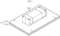
- FIG. 3 is a perspective view illustrating an outer appearance of the cell module assembly according to a preferred embodiment of the present disclosure.
- FIG. 4 is an exploded perspective view of FIG. 3 .
- FIG. 5 is a front view of FIG. 3 .
- the cell module assembly includes a cell module array 100 including a plurality of cell modules 100a, 100b, and 100c arranged at a predetermined interval, a pack structure 120 having a predetermined shape and receiving the cell modules 100a, 100b, and 100c, and a pack tray 121 located in the pack structure 120.
- a plurality of cells each having a main body having a thin plate shape, preferably, pouch-type secondary battery cells, are provided in each of the cell modules 100a, 100b, and 100c.
- the plurality of cells are arranged at a predetermined interval in a main body of each of the cell modules 100a, 100b, and 100c to form a stacked structure.
- At least one first venting hole 101 is formed in each of the cell modules 100a, 100b, and 100c, and a second venting hole 122 matched to the first venting hole 101 and communicating with a passage 115 is formed in the pack tray 121.
- the at least one first venting hole 101 is formed in a bottom surface of one end or both ends of each of the cell modules 100a, 100b, and 100c in a longitudinal direction of each of the cell modules 100a, 100b, and 100c to have a predetermined shape.
- the first venting hole 101 is a long hole.
- a sealing material is applied along edges of a bottom surface of each of the cell modules 100a, 100b, and 100c so that each of the cell modules 100a, 100b, and 100c is adhered to the pack array 121. Accordingly, a venting gas or a flame may be prevented from leaking to adjacent cell modules through an interface between each of the cell modules 100a, 100b, and 100c and the pack tray 121.
- a sealing material may be applied along edges of side surfaces of the cell modules 100a, 100b, and 100c so that adjacent cell modules are closely coupled to each other. Accordingly, the flow of a flame or a venting gas between adjacent cell modules may be more effectively prevented.
- a heat sink 110 contacting the cell modules 100a, 100b, and 100c may be added between the cell modules 100a, 100b, and 100c and the pack tray 121.
- a third venting hole 110a matched to the first venting hole 101 and the second venting hole 122 is formed in the heat sink 110.
- the pack structure 120 includes the pack tray 121 that supports the plurality of cell modules 100a, 100b, and 100c and in which the passage 115 is formed.
- the pack tray 121 includes a first plate 121a contacting the heat sink 110 and a second plate 121b located under the firs plate 121a and spaced apart by a predetermined interval from the first plate 121a.
- the passage 115 formed in the pack tray 121 is formed due to a gap between the first plate 121a and the second plate 121b. It is preferable that the gap between the first plate 121a and the second plate 121b is maintained by a support member 123 as shown in FIG. 5 .
- the passage 115 formed between the first plate 121a and the second plate 121b extends to the outside of the pack structure 120 along a predetermined discharge path.
- the cell module assembly constructed as described above may prevent a venting gas or a flame from flowing to the cell modules 100b and 110c adjacent to the cell module 100a.
- any one cell module e.g., the cell module 100a
- a venting gas or a flame generated in any one cell module is discharged through the first venting hole 101 formed in the cell module 100a, flows through the third venting hole 110a and the second venting hole 122 matched to the first venting hole 101 as marked by an arrow ⁇ , 1 of FIG. 1 , enters the passage 115 formed in the pack tray 121, horizontally flows through the passage 115 as marked by an arrow ⁇ , 2 , and then is discharged to the outside of the pack tray 121, an additional event may be prevented from occurring in the cell modules 100b and 100c adjacent to the cell module 100a.
- a cell assembly that may prevent a venting gas or a flame from diffusing to adjacent cell modules and may improve safety.
Landscapes
- Chemical & Material Sciences (AREA)
- Chemical Kinetics & Catalysis (AREA)
- Electrochemistry (AREA)
- General Chemical & Material Sciences (AREA)
- Engineering & Computer Science (AREA)
- Manufacturing & Machinery (AREA)
- Battery Mounting, Suspending (AREA)
- Cooling Or The Like Of Electrical Apparatus (AREA)
Abstract
Description
- The present application claims priority to Korean Patent Application No.
10-2016-0086899 filed on July 8, 2016 - The present disclosure relates to a cell module assembly, and more particularly, to a cell module assembly having a structure that may prevent a venting gas or a flame from diffusing to adjacent modules when an event occurs in a cell module.
- A lithium secondary battery pack is made by combining a plurality of unit cells into one pack and is widely used in applications requiring high energy such as a vehicle battery or an electric power storage device.
- However, a battery pack including a plurality of unit cells generates heat and swells up during overcharging, and thus is deformed such that a module expands outward. In a severe case, a flame is discharged to the outside of the module. Also, a venting gas or a flame generated in a cell module may diffuse to cell modules adjacent to the cell module, thereby leading to an additional event.
- In relation to technology for guaranteeing the safety of a cell module, Korean Patent Publication No.
2014-0002115 2015-0065964 - Korean Patent Publication No.
2014-0002115 - Korean Patent Publication No.
2015-0065964 - However, in a related art battery pack or a related art battery module having a structure in which a
cell module array 10 including a plurality ofcell modules 10a through 10c in apredetermined pack structure 30 contacts aheat sink 20 as shown inFIG. 1 , when an event occurs due to overcharging of a cell module (e.g., thecell module 10a), a venting gas or a flame may diffuse and an additional event may occur. Conventional patent documents have not disclosed technology for solving these problems, and thus there is a demand for the technology. - The present disclosure is designed to solve the problems of the related art, and therefore the present disclosure is directed to providing a cell module assembly having a structure for preventing occurrence of an additional event when an event occurs in a cell module and a venting gas or a flame diffuses to cell modules adjacent to the cell module, and a pack structure for the cell module assembly.
- In one aspect of the present disclosure, there is provided a cell module assembly including: a plurality of cell modules arranged at a predetermined interval; and a pack structure including a pack tray that supports the plurality of cell modules and in which a passage is formed, wherein at least one first venting hole is formed in each of the plurality of cell modules, and a second venting hole matched to the at least one first venting hole and communicating with the passage is formed in the pack tray.
- A sealing material may be applied along edges of a bottom surface of each of the plurality of cell modules so that each of the plurality of cell modules is adhered to the pack tray.
- A sealing material may be applied along edges of side surfaces of the plurality of cell modules so that adjacent cell modules are adhered to each other.
- The at least one first venting hole may be formed in a bottom surface of one end or both ends of each of the plurality of cell modules in a longitudinal direction of each of the plurality of cell modules.
- The cell module assembly may further include a heat sink located between the plurality of cell modules and the pack tray and contacting the plurality of cell modules, wherein a third venting hole matched to the at least one first venting hole and the second venting hole is formed in the heat sink.
- The pack tray may include a first plate contacting the heat sink and a second plate located under the first plate, wherein the passage is formed due to a gap between the first plate and the second plate.
- The second venting hole may be formed in the first plate.
- The passage extends to the outside of the pack structure.
- In another aspect of the present disclosure, there is also provided a pack structure including a pack tray having a support surface for supporting a cell module having a bottom surface in which a first venting hole is formed, wherein the pack tray includes: a second venting hole matched to the first venting hole; and a passage communicating with the second venting hole and discharging outward a venting gas and a flame that flow through the first venting hole and the second venting hole.
- The pack structure may further include a heat sink located between the cell module and the pack tray and contacting the cell module, wherein a third venting hole matched to the first venting hole and the second venting hole is formed in the heat sink.
- The pack tray may include a first plate contacting the heat sink and a second plate located under the first plate, wherein the passage is formed due to a gap between the first plate and the second plate.
- The second venting hole may be formed in the first plate.
- The first venting hole may be formed in a bottom surface of one end or both ends of the cell module in a longitudinal direction of the cell module, and the second venting hole may be formed to correspond to the first venting hole.
- In another aspect of the present disclosure, there is also provided a cell module provided in a pack tray provided in a pack structure, wherein a first venting hole is formed in a bottom surface of one end or both ends of a module body in a longitudinal direction of the module body and a venting gas and a flame are discharged into the pack tray.
- According to the present disclosure, when an event occurs in a cell module, since a venting gas or a flame may be discharged to the outside through a pack tray without affecting cell modules adjacent to the cell module, the safety of a cell assembly may be improved.
- The accompanying drawings illustrate a preferred embodiment of the present disclosure and together with the foregoing disclosure, serve to provide further understanding of the technical features of the present disclosure, and thus, the present disclosure is not construed as being limited to the drawing.
-
FIG. 1 is a front view of a cell module assembly according to the related art. -
FIG. 2 is a front view illustrating a configuration and an operation of a cell module assembly according to the present disclosure. -
FIG. 3 is a perspective view illustrating an outer appearance of the cell module assembly according to a preferred embodiment of the present disclosure. -
FIG. 4 is an exploded perspective view ofFIG. 3 . -
FIG. 5 is a front view ofFIG. 3 . -
FIG. 2 is a front view illustrating a configuration and an operation of a cell module assembly according to the present disclosure.FIG. 3 is a perspective view illustrating an outer appearance of the cell module assembly according to a preferred embodiment of the present disclosure.FIG. 4 is an exploded perspective view ofFIG. 3 .FIG. 5 is a front view ofFIG. 3 . - Referring to
FIGS. 2 through 5 , the cell module assembly according to the present disclosure includes acell module array 100 including a plurality ofcell modules pack structure 120 having a predetermined shape and receiving thecell modules pack tray 121 located in thepack structure 120. - A plurality of cells each having a main body having a thin plate shape, preferably, pouch-type secondary battery cells, are provided in each of the
cell modules cell modules - At least one first venting hole 101 (see
FIG. 4 ) is formed in each of thecell modules second venting hole 122 matched to thefirst venting hole 101 and communicating with apassage 115 is formed in thepack tray 121. - The at least one
first venting hole 101 is formed in a bottom surface of one end or both ends of each of thecell modules cell modules first venting hole 101 is a long hole. - A sealing material is applied along edges of a bottom surface of each of the
cell modules cell modules pack array 121. Accordingly, a venting gas or a flame may be prevented from leaking to adjacent cell modules through an interface between each of thecell modules pack tray 121. - In addition, a sealing material may be applied along edges of side surfaces of the
cell modules - A
heat sink 110 contacting thecell modules cell modules pack tray 121. Athird venting hole 110a matched to thefirst venting hole 101 and thesecond venting hole 122 is formed in theheat sink 110. - The
pack structure 120 includes thepack tray 121 that supports the plurality ofcell modules passage 115 is formed. Thepack tray 121 includes afirst plate 121a contacting theheat sink 110 and asecond plate 121b located under thefirs plate 121a and spaced apart by a predetermined interval from thefirst plate 121a. - It is preferable that the
passage 115 formed in thepack tray 121 is formed due to a gap between thefirst plate 121a and thesecond plate 121b. It is preferable that the gap between thefirst plate 121a and thesecond plate 121b is maintained by asupport member 123 as shown inFIG. 5 . - The
passage 115 formed between thefirst plate 121a and thesecond plate 121b extends to the outside of thepack structure 120 along a predetermined discharge path. - When an event due to overcharging or the like occurs in any one cell module (e.g., the
cell module 100a), the cell module assembly constructed as described above may prevent a venting gas or a flame from flowing to thecell modules 100b and 110c adjacent to thecell module 100a. - That is, since a venting gas or a flame generated in any one cell module (e.g., the
cell module 100a) is discharged through thefirst venting hole 101 formed in thecell module 100a, flows through thethird venting hole 110a and thesecond venting hole 122 matched to thefirst venting hole 101 as marked by an arrow ○,1 ofFIG. 1 , enters thepassage 115 formed in thepack tray 121, horizontally flows through thepassage 115 as marked by an arrow ○,2, and then is discharged to the outside of thepack tray 121, an additional event may be prevented from occurring in thecell modules cell module 100a. - As described above, when an event occurs in an arbitrary cell module, since a venting gas or a flame may be discharged to the outside of a pack structure without affecting adjacent cell modules, the safety of a cell assembly may be significantly improved.
- According to the present disclosure, there may be provided a cell assembly that may prevent a venting gas or a flame from diffusing to adjacent cell modules and may improve safety.
Claims (15)
- A cell module assembly comprising:a plurality of cell modules arranged at a predetermined interval; anda pack structure comprising a pack tray that supports the plurality of cell modules and in which a passage is formed,wherein at least one first venting hole is formed in each of the plurality of cell modules, anda second venting hole matched to the at least one first venting hole and communicating with the passage is formed in the pack tray.
- The cell module assembly of claim 1, wherein a sealing material is applied along edges of a bottom surface of each of the plurality of cell modules so that each of the plurality of cell modules is adhered to the pack tray.
- The cell module assembly of claim 2, wherein a sealing material is applied along edges of side surfaces of the plurality of cell modules so that adjacent cell modules are adhered to each other.
- The cell module assembly of claim 1, wherein the at least one first venting hole is formed in a bottom surface of one end or both ends of each of the plurality of cell modules in a longitudinal direction of each of the plurality of cell modules.
- The cell module assembly of claim 1, further comprising a heat sink located between the plurality of cell modules and the pack tray and contacting the plurality of cell modules,
wherein a third venting hole matched to the at least one first venting hole and the second venting hole is formed in the heat sink. - The cell module assembly of claim 5, wherein the pack tray comprises a first plate contacting the heat sink and a second plate located under the first plate,
wherein the passage is formed due to a gap between the first plate and the second plate. - The cell module assembly of claim 6, wherein the second venting hole is formed in the first plate.
- The cell module assembly of claim 6, wherein the passage extends to the outside of the pack structure.
- A pack structure comprising a pack tray having a support surface for supporting a cell module having a bottom surface in which a first venting hole is formed,
wherein the pack tray comprises:a second venting hole matched to the first venting hole; anda passage communicating with the second venting hole and discharging outward a venting gas and a flame that flow through the first venting hole and the second venting hole. - The pack structure of claim 9, further comprising a heat sink located between the cell module and the pack tray and contacting the cell module,
wherein a third venting hole matched to the first venting hole and the second venting hole is formed in the heat sink. - The pack structure of claim 10, wherein the pack tray comprises a first plate contacting the heat sink and a second plate located under the first plate,
wherein the passage is formed due to a gap between the first plate and the second plate. - The pack structure of claim 11, wherein the second venting hole is formed in the first plate.
- The pack structure of claim 12, wherein the first venting hole is formed in a bottom surface of one end or both ends of the cell module in a longitudinal direction of the cell module, and
the second venting hole is formed to correspond to the first venting hole. - The pack structure of claim 11, wherein the passage extends to the outside of the pack structure.
- A cell module provided in a pack tray provided in a pack structure,
wherein a first venting hole is formed in a bottom surface of one end or both ends of a module body in a longitudinal direction of the module body and a venting gas and a flame are discharged into the pack tray.
Priority Applications (1)
| Application Number | Priority Date | Filing Date | Title |
|---|---|---|---|
| PL17824594T PL3376557T3 (en) | 2016-07-08 | 2017-07-07 | Cell module assembly having improved safety and pack structure for the cell module assemply |
Applications Claiming Priority (2)
| Application Number | Priority Date | Filing Date | Title |
|---|---|---|---|
| KR1020160086899A KR20180006150A (en) | 2016-07-08 | 2016-07-08 | Cell module assembly improved in safety |
| PCT/KR2017/007326 WO2018009039A1 (en) | 2016-07-08 | 2017-07-07 | Cell module assembly having improved safety and pack structure therefor |
Publications (3)
| Publication Number | Publication Date |
|---|---|
| EP3376557A1 true EP3376557A1 (en) | 2018-09-19 |
| EP3376557A4 EP3376557A4 (en) | 2018-10-17 |
| EP3376557B1 EP3376557B1 (en) | 2020-12-16 |
Family
ID=60912923
Family Applications (1)
| Application Number | Title | Priority Date | Filing Date |
|---|---|---|---|
| EP17824594.0A Active EP3376557B1 (en) | 2016-07-08 | 2017-07-07 | Cell module assembly having improved safety and pack structure for the cell module assemply |
Country Status (6)
| Country | Link |
|---|---|
| US (1) | US10622610B2 (en) |
| EP (1) | EP3376557B1 (en) |
| KR (1) | KR20180006150A (en) |
| CN (1) | CN208422978U (en) |
| PL (1) | PL3376557T3 (en) |
| WO (1) | WO2018009039A1 (en) |
Cited By (2)
| Publication number | Priority date | Publication date | Assignee | Title |
|---|---|---|---|---|
| EP4096006A4 (en) * | 2020-07-14 | 2023-11-22 | LG Energy Solution, Ltd. | Battery module having venting hole terminal, and battery pack and vehicle including same |
| EP4170779A4 (en) * | 2021-06-22 | 2024-10-30 | LG Energy Solution, Ltd. | BATTERY MODULE AND BATTERY PACK |
Families Citing this family (40)
| Publication number | Priority date | Publication date | Assignee | Title |
|---|---|---|---|---|
| US12409756B2 (en) | 2017-04-05 | 2025-09-09 | H55 Sa | Aircraft monitoring system and method for electric or hybrid aircrafts |
| US11065979B1 (en) | 2017-04-05 | 2021-07-20 | H55 Sa | Aircraft monitoring system and method for electric or hybrid aircrafts |
| US10479223B2 (en) | 2018-01-25 | 2019-11-19 | H55 Sa | Construction and operation of electric or hybrid aircraft |
| US10854866B2 (en) * | 2019-04-08 | 2020-12-01 | H55 Sa | Power supply storage and fire management in electrically-driven aircraft |
| US11063323B2 (en) | 2019-01-23 | 2021-07-13 | H55 Sa | Battery module for electrically-driven aircraft |
| US11148819B2 (en) | 2019-01-23 | 2021-10-19 | H55 Sa | Battery module for electrically-driven aircraft |
| CN111384328A (en) * | 2018-12-29 | 2020-07-07 | 比亚迪股份有限公司 | Battery trays, power battery packs and vehicles |
| CN110190212B (en) * | 2018-12-29 | 2020-02-04 | 比亚迪股份有限公司 | Power battery pack and vehicle |
| CN110190211B (en) | 2018-12-29 | 2020-03-31 | 比亚迪股份有限公司 | Battery tray, power battery package and vehicle |
| US12230820B2 (en) | 2019-01-09 | 2025-02-18 | Byd Company Limited | Power battery pack and electric vehicle |
| CN111668406B (en) * | 2019-03-08 | 2021-12-07 | 比亚迪股份有限公司 | Battery tray, power battery package and vehicle |
| CN111668410B (en) * | 2019-03-08 | 2021-12-07 | 比亚迪股份有限公司 | Power battery package and vehicle |
| CN111668408B (en) * | 2019-03-08 | 2022-03-15 | 比亚迪股份有限公司 | Battery trays, power battery packs and vehicles |
| KR102162999B1 (en) * | 2019-04-12 | 2020-10-07 | 서창전기통신 주식회사 | Energy storage system with fault diagnosis function of battery |
| KR102751111B1 (en) | 2019-06-17 | 2025-01-06 | 주식회사 엘지에너지솔루션 | Battery Module Comprising Base Plate having Gas Discharge Passage and Battery Pack and Energy Storage System |
| KR102187163B1 (en) | 2019-07-04 | 2020-12-04 | 주식회사 피플웍스 | Cell module assembly |
| KR102829076B1 (en) | 2020-03-19 | 2025-07-02 | 주식회사 엘지에너지솔루션 | Battery pack with structure of improved convenience for carrying and assembling and improved safety, and Energy storage system comprising the same |
| KR102807490B1 (en) | 2020-04-01 | 2025-05-13 | 주식회사 엘지에너지솔루션 | Battery module and battery pack including the same |
| KR102821925B1 (en) | 2020-04-29 | 2025-06-17 | 주식회사 엘지에너지솔루션 | Battery Pack and Electronic Device Comprising the Same and Vehicle |
| KR102922131B1 (en) | 2020-04-29 | 2026-02-02 | 주식회사 엘지에너지솔루션 | Battery pack and device including the same |
| KR102767703B1 (en) | 2020-04-29 | 2025-02-12 | 주식회사 엘지에너지솔루션 | Battery pack and device including the same |
| CN111969157A (en) * | 2020-08-21 | 2020-11-20 | 常州瑞德丰精密技术有限公司 | Battery pack, electric automobile and energy storage device |
| WO2022099661A1 (en) * | 2020-11-13 | 2022-05-19 | 江苏时代新能源科技有限公司 | Box, battery, electrical device, and method for manufacturing battery |
| JP7186760B2 (en) * | 2020-12-21 | 2022-12-09 | プライムプラネットエナジー&ソリューションズ株式会社 | storage module |
| ES3057109T3 (en) * | 2021-01-11 | 2026-02-26 | Lg Energy Solution Ltd | Battery pack and vehicle including same |
| CN112751131B (en) * | 2021-01-22 | 2024-04-19 | 上海兰钧新能源科技有限公司 | Novel battery box structure, battery pack and electric vehicle |
| KR102919208B1 (en) | 2021-03-23 | 2026-01-27 | 주식회사 엘지에너지솔루션 | A battery module with a heat propagation repression structure using coolant and a battery pack including the same |
| EP4213288A4 (en) * | 2021-05-28 | 2024-12-11 | LG Energy Solution, Ltd. | COOLING DEVICE, BATTERY MODULE, ENERGY STORAGE SYSTEM COMPRISING THE SAME, AND MOTOR VEHICLE |
| KR102776122B1 (en) * | 2021-06-21 | 2025-03-04 | 주식회사 엘지에너지솔루션 | Battery pack with improved gas venting path |
| KR20230016531A (en) * | 2021-07-26 | 2023-02-02 | 주식회사 엘지에너지솔루션 | Battery rack and energy storage system comprising the battery rack |
| KR102664969B1 (en) | 2022-01-26 | 2024-05-10 | 주식회사 엘지에너지솔루션 | Battery pack and a vehicle having the same |
| KR20230162850A (en) * | 2022-05-20 | 2023-11-29 | 주식회사 엘지에너지솔루션 | Prismatic secondary battery |
| EP4391177A4 (en) * | 2022-07-20 | 2025-07-02 | Lg Energy Solution Ltd | BATTERY PACK AND VEHICLE WITH IT |
| DE102022118977B3 (en) | 2022-07-28 | 2023-10-05 | Dr. Ing. H.C. F. Porsche Aktiengesellschaft | Underbody protection device for arrangement below a traction battery on the underbody of an at least partially electrically driven motor vehicle |
| KR102949021B1 (en) * | 2022-09-06 | 2026-04-03 | 주식회사 엘지에너지솔루션 | Battery pack and vehicle including the same |
| DE102022211202A1 (en) | 2022-10-21 | 2024-05-02 | Volkswagen Aktiengesellschaft | Battery system for an electrically powered vehicle |
| CN120752795A (en) * | 2023-08-14 | 2025-10-03 | 株式会社Lg新能源 | Battery assembly, battery pack, and vehicle including the battery pack |
| EP4614709A4 (en) * | 2023-09-22 | 2026-04-15 | Lg Energy Solution Ltd | BATTERY PACK AND VEHICLE WITH IT |
| DE102023133751A1 (en) | 2023-12-01 | 2025-06-05 | Georg Fritzmeier - GmbH & Co. KG | Thermoplastic support structure, underbody protection device and motor vehicle with underbody protection device |
| DE102023133874B3 (en) | 2023-12-04 | 2025-05-22 | Georg Fritzmeier - GmbH & Co. KG | Underrun protection with thermally optimized reinforcement, underrun protection battery module and motor vehicle with improved underbody protection device |
Family Cites Families (11)
| Publication number | Priority date | Publication date | Assignee | Title |
|---|---|---|---|---|
| JPS5914828B2 (en) | 1979-11-27 | 1984-04-06 | 沖電気工業株式会社 | decoder circuit |
| JP4812345B2 (en) | 2005-06-30 | 2011-11-09 | 三洋電機株式会社 | Power supply |
| JP2007027011A (en) | 2005-07-20 | 2007-02-01 | Sanyo Electric Co Ltd | Power supply |
| DE102009046385A1 (en) | 2009-11-04 | 2011-05-05 | SB LiMotive Company Ltd., Suwon | Battery with degassing system and method for discharging spills |
| EP2325922B1 (en) * | 2009-11-19 | 2012-05-09 | SB LiMotive Co., Ltd. | Battery pack |
| KR101199148B1 (en) | 2011-04-21 | 2012-11-09 | 에스비리모티브 주식회사 | Battery module |
| EP2738834B1 (en) | 2011-07-29 | 2019-03-20 | Panasonic Intellectual Property Management Co., Ltd. | Battery pack |
| KR101913384B1 (en) | 2012-06-28 | 2018-12-28 | 에스케이이노베이션 주식회사 | Battery pack |
| KR102113155B1 (en) * | 2013-11-25 | 2020-05-20 | 에스케이이노베이션 주식회사 | Battery module and battery pack |
| JP5892148B2 (en) | 2013-12-04 | 2016-03-23 | 株式会社豊田自動織機 | Battery module unit |
| KR101773105B1 (en) * | 2014-07-31 | 2017-08-30 | 주식회사 엘지화학 | Battery module |
-
2016
- 2016-07-08 KR KR1020160086899A patent/KR20180006150A/en not_active Ceased
-
2017
- 2017-07-07 WO PCT/KR2017/007326 patent/WO2018009039A1/en not_active Ceased
- 2017-07-07 PL PL17824594T patent/PL3376557T3/en unknown
- 2017-07-07 US US16/060,278 patent/US10622610B2/en active Active
- 2017-07-07 CN CN201790000482.8U patent/CN208422978U/en active Active
- 2017-07-07 EP EP17824594.0A patent/EP3376557B1/en active Active
Cited By (2)
| Publication number | Priority date | Publication date | Assignee | Title |
|---|---|---|---|---|
| EP4096006A4 (en) * | 2020-07-14 | 2023-11-22 | LG Energy Solution, Ltd. | Battery module having venting hole terminal, and battery pack and vehicle including same |
| EP4170779A4 (en) * | 2021-06-22 | 2024-10-30 | LG Energy Solution, Ltd. | BATTERY MODULE AND BATTERY PACK |
Also Published As
| Publication number | Publication date |
|---|---|
| WO2018009039A1 (en) | 2018-01-11 |
| US20180358593A1 (en) | 2018-12-13 |
| CN208422978U (en) | 2019-01-22 |
| EP3376557A4 (en) | 2018-10-17 |
| PL3376557T3 (en) | 2021-05-31 |
| US10622610B2 (en) | 2020-04-14 |
| EP3376557B1 (en) | 2020-12-16 |
| KR20180006150A (en) | 2018-01-17 |
Similar Documents
| Publication | Publication Date | Title |
|---|---|---|
| EP3376557B1 (en) | Cell module assembly having improved safety and pack structure for the cell module assemply | |
| US11777158B2 (en) | Battery module and battery pack including same | |
| US11462799B2 (en) | Battery module having gas discharge structure | |
| US11824175B2 (en) | Battery module | |
| EP3716392B1 (en) | Battery module having improved cooling structure | |
| US11063317B2 (en) | Battery pack | |
| US9548475B2 (en) | Battery cell of irregular structure and battery module employed with the same | |
| US8597809B2 (en) | Rechargeable battery | |
| US11646464B2 (en) | Battery module and battery pack comprising same | |
| CN107851749B (en) | Battery module having structure in which battery management system is directly connected to terminal board | |
| US20150207131A1 (en) | Battery module having short-circuit connection member | |
| US20160211499A1 (en) | Battery module | |
| KR102113155B1 (en) | Battery module and battery pack | |
| KR20150047417A (en) | Rechargeable battery having fuse and battery module | |
| KR102384308B1 (en) | Pouch-type Battery Cell Having Venting Member and Battery Pack Comprising the Same | |
| US20240088516A1 (en) | Battery rack and energy storage system comprising the same | |
| US20230268612A1 (en) | Battery pack and vehicle comprising same | |
| CN115039280A (en) | Battery pack and apparatus including the same | |
| EP4432446B1 (en) | Battery module, and battery pack and vehicle including the same | |
| EP4478486A1 (en) | Battery module, and battery module manufacturing method | |
| US20240258605A1 (en) | Battery module, battery pack including the battery module, and energy storage system and vehicle including the battery pack | |
| EP4492556A1 (en) | Battery pack | |
| KR20250085299A (en) | Battery module | |
| CN117413421A (en) | Battery modules and battery packs and vehicles including the battery modules |
Legal Events
| Date | Code | Title | Description |
|---|---|---|---|
| STAA | Information on the status of an ep patent application or granted ep patent |
Free format text: STATUS: THE INTERNATIONAL PUBLICATION HAS BEEN MADE |
|
| PUAI | Public reference made under article 153(3) epc to a published international application that has entered the european phase |
Free format text: ORIGINAL CODE: 0009012 |
|
| STAA | Information on the status of an ep patent application or granted ep patent |
Free format text: STATUS: REQUEST FOR EXAMINATION WAS MADE |
|
| 17P | Request for examination filed |
Effective date: 20180613 |
|
| AK | Designated contracting states |
Kind code of ref document: A1 Designated state(s): AL AT BE BG CH CY CZ DE DK EE ES FI FR GB GR HR HU IE IS IT LI LT LU LV MC MK MT NL NO PL PT RO RS SE SI SK SM TR |
|
| AX | Request for extension of the european patent |
Extension state: BA ME |
|
| A4 | Supplementary search report drawn up and despatched |
Effective date: 20180917 |
|
| RIC1 | Information provided on ipc code assigned before grant |
Ipc: H01M 2/10 20060101AFI20180911BHEP Ipc: H01M 2/12 20060101ALI20180911BHEP Ipc: H01M 2/34 20060101ALI20180911BHEP |
|
| STAA | Information on the status of an ep patent application or granted ep patent |
Free format text: STATUS: EXAMINATION IS IN PROGRESS |
|
| 17Q | First examination report despatched |
Effective date: 20190709 |
|
| DAV | Request for validation of the european patent (deleted) | ||
| DAX | Request for extension of the european patent (deleted) | ||
| GRAP | Despatch of communication of intention to grant a patent |
Free format text: ORIGINAL CODE: EPIDOSNIGR1 |
|
| STAA | Information on the status of an ep patent application or granted ep patent |
Free format text: STATUS: GRANT OF PATENT IS INTENDED |
|
| INTG | Intention to grant announced |
Effective date: 20200923 |
|
| GRAS | Grant fee paid |
Free format text: ORIGINAL CODE: EPIDOSNIGR3 |
|
| GRAA | (expected) grant |
Free format text: ORIGINAL CODE: 0009210 |
|
| STAA | Information on the status of an ep patent application or granted ep patent |
Free format text: STATUS: THE PATENT HAS BEEN GRANTED |
|
| REG | Reference to a national code |
Ref country code: DE Ref legal event code: R079 Ref document number: 602017029782 Country of ref document: DE Free format text: PREVIOUS MAIN CLASS: H01M0002100000 Ipc: H01M0050200000 |
|
| AK | Designated contracting states |
Kind code of ref document: B1 Designated state(s): AL AT BE BG CH CY CZ DE DK EE ES FI FR GB GR HR HU IE IS IT LI LT LU LV MC MK MT NL NO PL PT RO RS SE SI SK SM TR |
|
| REG | Reference to a national code |
Ref country code: GB Ref legal event code: FG4D |
|
| REG | Reference to a national code |
Ref country code: IE Ref legal event code: FG4D |
|
| REG | Reference to a national code |
Ref country code: DE Ref legal event code: R096 Ref document number: 602017029782 Country of ref document: DE |
|
| REG | Reference to a national code |
Ref country code: AT Ref legal event code: REF Ref document number: 1346393 Country of ref document: AT Kind code of ref document: T Effective date: 20210115 |
|
| REG | Reference to a national code |
Ref country code: SE Ref legal event code: TRGR |
|
| PG25 | Lapsed in a contracting state [announced via postgrant information from national office to epo] |
Ref country code: GR Free format text: LAPSE BECAUSE OF FAILURE TO SUBMIT A TRANSLATION OF THE DESCRIPTION OR TO PAY THE FEE WITHIN THE PRESCRIBED TIME-LIMIT Effective date: 20210317 Ref country code: NO Free format text: LAPSE BECAUSE OF FAILURE TO SUBMIT A TRANSLATION OF THE DESCRIPTION OR TO PAY THE FEE WITHIN THE PRESCRIBED TIME-LIMIT Effective date: 20210316 Ref country code: RS Free format text: LAPSE BECAUSE OF FAILURE TO SUBMIT A TRANSLATION OF THE DESCRIPTION OR TO PAY THE FEE WITHIN THE PRESCRIBED TIME-LIMIT Effective date: 20201216 Ref country code: FI Free format text: LAPSE BECAUSE OF FAILURE TO SUBMIT A TRANSLATION OF THE DESCRIPTION OR TO PAY THE FEE WITHIN THE PRESCRIBED TIME-LIMIT Effective date: 20201216 |
|
| REG | Reference to a national code |
Ref country code: AT Ref legal event code: MK05 Ref document number: 1346393 Country of ref document: AT Kind code of ref document: T Effective date: 20201216 |
|
| REG | Reference to a national code |
Ref country code: NL Ref legal event code: MP Effective date: 20201216 |
|
| PG25 | Lapsed in a contracting state [announced via postgrant information from national office to epo] |
Ref country code: BG Free format text: LAPSE BECAUSE OF FAILURE TO SUBMIT A TRANSLATION OF THE DESCRIPTION OR TO PAY THE FEE WITHIN THE PRESCRIBED TIME-LIMIT Effective date: 20210316 Ref country code: LV Free format text: LAPSE BECAUSE OF FAILURE TO SUBMIT A TRANSLATION OF THE DESCRIPTION OR TO PAY THE FEE WITHIN THE PRESCRIBED TIME-LIMIT Effective date: 20201216 |
|
| PG25 | Lapsed in a contracting state [announced via postgrant information from national office to epo] |
Ref country code: HR Free format text: LAPSE BECAUSE OF FAILURE TO SUBMIT A TRANSLATION OF THE DESCRIPTION OR TO PAY THE FEE WITHIN THE PRESCRIBED TIME-LIMIT Effective date: 20201216 Ref country code: NL Free format text: LAPSE BECAUSE OF FAILURE TO SUBMIT A TRANSLATION OF THE DESCRIPTION OR TO PAY THE FEE WITHIN THE PRESCRIBED TIME-LIMIT Effective date: 20201216 |
|
| REG | Reference to a national code |
Ref country code: LT Ref legal event code: MG9D |
|
| PG25 | Lapsed in a contracting state [announced via postgrant information from national office to epo] |
Ref country code: SM Free format text: LAPSE BECAUSE OF FAILURE TO SUBMIT A TRANSLATION OF THE DESCRIPTION OR TO PAY THE FEE WITHIN THE PRESCRIBED TIME-LIMIT Effective date: 20201216 Ref country code: LT Free format text: LAPSE BECAUSE OF FAILURE TO SUBMIT A TRANSLATION OF THE DESCRIPTION OR TO PAY THE FEE WITHIN THE PRESCRIBED TIME-LIMIT Effective date: 20201216 Ref country code: EE Free format text: LAPSE BECAUSE OF FAILURE TO SUBMIT A TRANSLATION OF THE DESCRIPTION OR TO PAY THE FEE WITHIN THE PRESCRIBED TIME-LIMIT Effective date: 20201216 Ref country code: CZ Free format text: LAPSE BECAUSE OF FAILURE TO SUBMIT A TRANSLATION OF THE DESCRIPTION OR TO PAY THE FEE WITHIN THE PRESCRIBED TIME-LIMIT Effective date: 20201216 Ref country code: RO Free format text: LAPSE BECAUSE OF FAILURE TO SUBMIT A TRANSLATION OF THE DESCRIPTION OR TO PAY THE FEE WITHIN THE PRESCRIBED TIME-LIMIT Effective date: 20201216 Ref country code: SK Free format text: LAPSE BECAUSE OF FAILURE TO SUBMIT A TRANSLATION OF THE DESCRIPTION OR TO PAY THE FEE WITHIN THE PRESCRIBED TIME-LIMIT Effective date: 20201216 Ref country code: PT Free format text: LAPSE BECAUSE OF FAILURE TO SUBMIT A TRANSLATION OF THE DESCRIPTION OR TO PAY THE FEE WITHIN THE PRESCRIBED TIME-LIMIT Effective date: 20210416 |
|
| PG25 | Lapsed in a contracting state [announced via postgrant information from national office to epo] |
Ref country code: AT Free format text: LAPSE BECAUSE OF FAILURE TO SUBMIT A TRANSLATION OF THE DESCRIPTION OR TO PAY THE FEE WITHIN THE PRESCRIBED TIME-LIMIT Effective date: 20201216 |
|
| REG | Reference to a national code |
Ref country code: DE Ref legal event code: R097 Ref document number: 602017029782 Country of ref document: DE |
|
| PG25 | Lapsed in a contracting state [announced via postgrant information from national office to epo] |
Ref country code: IS Free format text: LAPSE BECAUSE OF FAILURE TO SUBMIT A TRANSLATION OF THE DESCRIPTION OR TO PAY THE FEE WITHIN THE PRESCRIBED TIME-LIMIT Effective date: 20210416 |
|
| PLBE | No opposition filed within time limit |
Free format text: ORIGINAL CODE: 0009261 |
|
| STAA | Information on the status of an ep patent application or granted ep patent |
Free format text: STATUS: NO OPPOSITION FILED WITHIN TIME LIMIT |
|
| PG25 | Lapsed in a contracting state [announced via postgrant information from national office to epo] |
Ref country code: AL Free format text: LAPSE BECAUSE OF FAILURE TO SUBMIT A TRANSLATION OF THE DESCRIPTION OR TO PAY THE FEE WITHIN THE PRESCRIBED TIME-LIMIT Effective date: 20201216 Ref country code: IT Free format text: LAPSE BECAUSE OF FAILURE TO SUBMIT A TRANSLATION OF THE DESCRIPTION OR TO PAY THE FEE WITHIN THE PRESCRIBED TIME-LIMIT Effective date: 20201216 |
|
| 26N | No opposition filed |
Effective date: 20210917 |
|
| PG25 | Lapsed in a contracting state [announced via postgrant information from national office to epo] |
Ref country code: DK Free format text: LAPSE BECAUSE OF FAILURE TO SUBMIT A TRANSLATION OF THE DESCRIPTION OR TO PAY THE FEE WITHIN THE PRESCRIBED TIME-LIMIT Effective date: 20201216 |
|
| PG25 | Lapsed in a contracting state [announced via postgrant information from national office to epo] |
Ref country code: ES Free format text: LAPSE BECAUSE OF FAILURE TO SUBMIT A TRANSLATION OF THE DESCRIPTION OR TO PAY THE FEE WITHIN THE PRESCRIBED TIME-LIMIT Effective date: 20201216 |
|
| PG25 | Lapsed in a contracting state [announced via postgrant information from national office to epo] |
Ref country code: SI Free format text: LAPSE BECAUSE OF FAILURE TO SUBMIT A TRANSLATION OF THE DESCRIPTION OR TO PAY THE FEE WITHIN THE PRESCRIBED TIME-LIMIT Effective date: 20201216 |
|
| REG | Reference to a national code |
Ref country code: CH Ref legal event code: PL |
|
| PG25 | Lapsed in a contracting state [announced via postgrant information from national office to epo] |
Ref country code: MC Free format text: LAPSE BECAUSE OF FAILURE TO SUBMIT A TRANSLATION OF THE DESCRIPTION OR TO PAY THE FEE WITHIN THE PRESCRIBED TIME-LIMIT Effective date: 20201216 |
|
| REG | Reference to a national code |
Ref country code: BE Ref legal event code: MM Effective date: 20210731 |
|
| PG25 | Lapsed in a contracting state [announced via postgrant information from national office to epo] |
Ref country code: LI Free format text: LAPSE BECAUSE OF NON-PAYMENT OF DUE FEES Effective date: 20210731 Ref country code: CH Free format text: LAPSE BECAUSE OF NON-PAYMENT OF DUE FEES Effective date: 20210731 |
|
| PG25 | Lapsed in a contracting state [announced via postgrant information from national office to epo] |
Ref country code: IS Free format text: LAPSE BECAUSE OF FAILURE TO SUBMIT A TRANSLATION OF THE DESCRIPTION OR TO PAY THE FEE WITHIN THE PRESCRIBED TIME-LIMIT Effective date: 20210416 Ref country code: LU Free format text: LAPSE BECAUSE OF NON-PAYMENT OF DUE FEES Effective date: 20210707 |
|
| PG25 | Lapsed in a contracting state [announced via postgrant information from national office to epo] |
Ref country code: IE Free format text: LAPSE BECAUSE OF NON-PAYMENT OF DUE FEES Effective date: 20210707 Ref country code: BE Free format text: LAPSE BECAUSE OF NON-PAYMENT OF DUE FEES Effective date: 20210731 |
|
| REG | Reference to a national code |
Ref country code: DE Ref legal event code: R081 Ref document number: 602017029782 Country of ref document: DE Owner name: LG ENERGY SOLUTION, LTD., KR Free format text: FORMER OWNER: LG CHEM, LTD., SEOUL, KR |
|
| P01 | Opt-out of the competence of the unified patent court (upc) registered |
Effective date: 20230512 |
|
| PG25 | Lapsed in a contracting state [announced via postgrant information from national office to epo] |
Ref country code: CY Free format text: LAPSE BECAUSE OF FAILURE TO SUBMIT A TRANSLATION OF THE DESCRIPTION OR TO PAY THE FEE WITHIN THE PRESCRIBED TIME-LIMIT Effective date: 20201216 |
|
| PG25 | Lapsed in a contracting state [announced via postgrant information from national office to epo] |
Ref country code: HU Free format text: LAPSE BECAUSE OF FAILURE TO SUBMIT A TRANSLATION OF THE DESCRIPTION OR TO PAY THE FEE WITHIN THE PRESCRIBED TIME-LIMIT; INVALID AB INITIO Effective date: 20170707 |
|
| REG | Reference to a national code |
Ref country code: GB Ref legal event code: 732E Free format text: REGISTERED BETWEEN 20230901 AND 20230906 |
|
| PG25 | Lapsed in a contracting state [announced via postgrant information from national office to epo] |
Ref country code: MK Free format text: LAPSE BECAUSE OF FAILURE TO SUBMIT A TRANSLATION OF THE DESCRIPTION OR TO PAY THE FEE WITHIN THE PRESCRIBED TIME-LIMIT Effective date: 20201216 |
|
| PG25 | Lapsed in a contracting state [announced via postgrant information from national office to epo] |
Ref country code: MT Free format text: LAPSE BECAUSE OF FAILURE TO SUBMIT A TRANSLATION OF THE DESCRIPTION OR TO PAY THE FEE WITHIN THE PRESCRIBED TIME-LIMIT Effective date: 20201216 |
|
| PGFP | Annual fee paid to national office [announced via postgrant information from national office to epo] |
Ref country code: PL Payment date: 20250625 Year of fee payment: 9 |
|
| PGFP | Annual fee paid to national office [announced via postgrant information from national office to epo] |
Ref country code: GB Payment date: 20250624 Year of fee payment: 9 |
|
| PGFP | Annual fee paid to national office [announced via postgrant information from national office to epo] |
Ref country code: FR Payment date: 20250624 Year of fee payment: 9 |
|
| PGFP | Annual fee paid to national office [announced via postgrant information from national office to epo] |
Ref country code: SE Payment date: 20250624 Year of fee payment: 9 |
|
| PGFP | Annual fee paid to national office [announced via postgrant information from national office to epo] |
Ref country code: DE Payment date: 20250624 Year of fee payment: 9 |
|
| PG25 | Lapsed in a contracting state [announced via postgrant information from national office to epo] |
Ref country code: TR Free format text: LAPSE BECAUSE OF FAILURE TO SUBMIT A TRANSLATION OF THE DESCRIPTION OR TO PAY THE FEE WITHIN THE PRESCRIBED TIME-LIMIT Effective date: 20201216 |