EP3376435A1 - Image processing apparatus, image processing system, image processing method, and program - Google Patents
Image processing apparatus, image processing system, image processing method, and program Download PDFInfo
- Publication number
- EP3376435A1 EP3376435A1 EP18160898.5A EP18160898A EP3376435A1 EP 3376435 A1 EP3376435 A1 EP 3376435A1 EP 18160898 A EP18160898 A EP 18160898A EP 3376435 A1 EP3376435 A1 EP 3376435A1
- Authority
- EP
- European Patent Office
- Prior art keywords
- image
- dimensional data
- unit
- generation unit
- image processing
- Prior art date
- Legal status (The legal status is an assumption and is not a legal conclusion. Google has not performed a legal analysis and makes no representation as to the accuracy of the status listed.)
- Granted
Links
Images




Classifications
-
- G—PHYSICS
- G06—COMPUTING OR CALCULATING; COUNTING
- G06V—IMAGE OR VIDEO RECOGNITION OR UNDERSTANDING
- G06V20/00—Scenes; Scene-specific elements
- G06V20/60—Type of objects
- G06V20/64—Three-dimensional [3D] objects
- G06V20/647—Three-dimensional [3D] objects by matching two-dimensional images to three-dimensional objects
-
- G—PHYSICS
- G06—COMPUTING OR CALCULATING; COUNTING
- G06V—IMAGE OR VIDEO RECOGNITION OR UNDERSTANDING
- G06V10/00—Arrangements for image or video recognition or understanding
- G06V10/10—Image acquisition
- G06V10/12—Details of acquisition arrangements; Constructional details thereof
- G06V10/14—Optical characteristics of the device performing the acquisition or on the illumination arrangements
- G06V10/147—Details of sensors, e.g. sensor lenses
-
- G—PHYSICS
- G06—COMPUTING OR CALCULATING; COUNTING
- G06V—IMAGE OR VIDEO RECOGNITION OR UNDERSTANDING
- G06V20/00—Scenes; Scene-specific elements
- G06V20/50—Context or environment of the image
- G06V20/56—Context or environment of the image exterior to a vehicle by using sensors mounted on the vehicle
- G06V20/58—Recognition of moving objects or obstacles, e.g. vehicles or pedestrians; Recognition of traffic objects, e.g. traffic signs, traffic lights or roads
- G06V20/582—Recognition of moving objects or obstacles, e.g. vehicles or pedestrians; Recognition of traffic objects, e.g. traffic signs, traffic lights or roads of traffic signs
-
- G—PHYSICS
- G06—COMPUTING OR CALCULATING; COUNTING
- G06V—IMAGE OR VIDEO RECOGNITION OR UNDERSTANDING
- G06V20/00—Scenes; Scene-specific elements
- G06V20/60—Type of objects
- G06V20/62—Text, e.g. of license plates, overlay texts or captions on TV images
-
- G—PHYSICS
- G06—COMPUTING OR CALCULATING; COUNTING
- G06V—IMAGE OR VIDEO RECOGNITION OR UNDERSTANDING
- G06V30/00—Character recognition; Recognising digital ink; Document-oriented image-based pattern recognition
- G06V30/40—Document-oriented image-based pattern recognition
- G06V30/42—Document-oriented image-based pattern recognition based on the type of document
- G06V30/424—Postal images, e.g. labels or addresses on parcels or postal envelopes
-
- G—PHYSICS
- G06—COMPUTING OR CALCULATING; COUNTING
- G06V—IMAGE OR VIDEO RECOGNITION OR UNDERSTANDING
- G06V2201/00—Indexing scheme relating to image or video recognition or understanding
- G06V2201/06—Recognition of objects for industrial automation
Definitions
- Exemplary embodiments described herein relate to image processing apparatuses, image processing systems, image processing methods, and programs.
- OCR optical character recognition
- the OCR apparatus can correct the deformation of an image of the shipping label by image processing to recognize address information written on the shipping label. However, if the shipping label is significantly deformed, the OCR apparatus may falsely recognize or fail to recognize the shipping label.
- An image processing apparatus in accordance with an embodiment has a three-dimensional data generation unit, a two-dimensional data generation unit, and a recognition image generation unit.
- the three-dimensional data generation unit generates three-dimensional data of an object on the basis of an image of the object on which object information represented by a character or a symbol is attached, and a distance image indicating a distance between a reference position and the object for each pixel.
- the two-dimensional data generation unit generates two-dimensional data by flattening the three-dimensional data generated by the three-dimensional data generation unit.
- the recognition image generation unit generates a recognition image which is used to recognize the object information, on the basis of the two-dimensional data generated by the two-dimensional data generation unit.
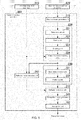
- FIG. 1 is a diagram showing an overall configuration of an image processing system 10 in accordance with a first embodiment.
- the image processing system 10 of this embodiment includes an image acquisition apparatus 100, an image processing apparatus 200, a sorting apparatus 300, and a video coding system (VCS) 500.
- VCS video coding system
- the image processing apparatus 200 is communicatively coupled to the image acquisition apparatus 100 and the sorting apparatus 300.
- the image processing apparatus 200 is also coupled to the VCS 500 through a network NW.
- the network NW is, for example, a wide area network (WAN), a local area network (LAN), etc.
- the image acquisition apparatus 100 includes a first image acquisition unit 110, a second image acquisition unit 120, an illumination device 130, and an illumination device 140.
- the first image acquisition unit 110 is, for example, a line scan sensor including a linear array of charge-coupled device (CCD) or complementary metal oxide semiconductor (CMOS) sensors.
- the illumination devices 130 and 140 illuminate a package (example object) 400 on a conveyor belt 310.
- the first image acquisition unit 110 performs successive shooting to acquire an image of the package 400 as it is being transported by the conveyor belt 310 at a constant speed.
- the image acquisition apparatus 100 sends the image of the package 400 acquired by the first image acquisition unit 110 to the image processing apparatus 200.
- FIG. 2 is a diagram showing an example process of measuring a distance using the second image acquisition unit 120 in accordance with the first embodiment.
- the second image acquisition unit 120 is, for example, a stereo camera, which captures a plurality of images from different viewpoints.
- the second image acquisition unit 120 is used to generate a distance image of the package 400.
- the second image acquisition unit 120 includes a first camera 121 and a second camera 122.
- the first camera 121 captures a left image.
- the second camera 122 captures a right image.
- the Y-axis is an axis extending in a direction that the package 400 is transported.
- the Z-axis is an axis extending in a height direction of the package 400.
- the X-axis is an axis extending in a direction that is perpendicular to the Y-direction and the Z-direction.
- a position in the Z-axis direction of a line connecting the first camera 121 and the second camera 122 is hereinafter referred to as a "reference position.”
- a left image surface 123 and a right image surface 124 are shown.
- a distance (baseline length) between the first camera 121 and the second camera 122 is represented by B
- a focal length is represented by F
- a distance between the reference position and the package 400 is represented by DZ
- a difference between a position of the package 400 in the left image and a center of the left image is represented by DL
- a difference between a position of the package 400 in the right image and a center of the right image is represented by DR.
- the focal length F is determined by a lens used in the first camera 121 and the second camera 122.
- the distance B is determined by a position of the first camera 121 and a position of the second camera 122.
- the disparity d is calculated by performing template matching on the left image and the right image.
- the second image acquisition unit 120 sends the acquired right and left images to the image processing apparatus 200.
- the image processing apparatus 200 can generate a distance image of the package 400 by calculating the distance DZ for each pixel on the basis of the right and left images received from the second image acquisition unit 120.
- the distance image has a luminance value that increases (or decreases) with an increase in distance, for example.
- the image acquisition apparatus 100 sends the generated distance image to the image processing apparatus 200.
- the image processing apparatus 200 recognizes address information (object information) written in a shipping label region (a region where the object information is present) 410 of the package 400, on the basis of the image of the package 400 and the generated distance image received from the image acquisition apparatus 100.
- the image processing apparatus 200 sends the recognition result (address information) to the sorting apparatus 300.
- the address information includes, for example, a postal code written in numerals, an address written in characters, numerals, and symbols, or a combination thereof.
- the sorting apparatus 300 includes, for example, a plurality of sorting pockets (not shown) arranged in a plurality of separate stages and a plurality of separate rows, and a VCS pocket (not shown).
- the sorting apparatus 300 switches sorting destinations of packages 400 transported on the conveyor belt 310, depending on the recognition result (address information) received from the image processing apparatus 200, so that the packages 400 are accumulated in their sorting destinations, i.e., sorting pockets.
- the image processing apparatus 200 When the image processing apparatus 200 has failed to recognize the address information written in the shipping label region 410, the image processing apparatus 200 sends, to the sorting apparatus 300, a notification indicating the failure to recognize the address information.
- the sorting apparatus 300 When the sorting apparatus 300 has received the notification indicating the failure to recognize the address information from the image processing apparatus 200, the sorting apparatus 300 switches the sorting destination of the package 400 to the VCS pocket.
- the image processing apparatus 200 when the image processing apparatus 200 has failed to recognize the address information written in the shipping label region 410, the image processing apparatus 200 sends the image data of the package 400 and a video coding (VC) request to the VCS 500 through the network NW.
- VC video coding
- the VCS 500 is a system that displays the image of the package 400 the address information of which has not been successfully recognized by the image processing apparatus 200, and assists recognizing the address information by visibility of an operator.
- the VCS 500 includes a plurality of terminals. Each terminal displays the image of the package 400 on a display device, and receives address information that is input by an operator through an input device, such as a keyboard or a touch panel.
- the VCS 500 When the VCS 500 has received address information input by an operator, the VCS 500 sends the input address information to the image processing apparatus 200 through the network NW.
- the address information is used when the package 400 which is accumulated in the VCS pocket is processed again. As a result, the package 400 the address information of which has not been successfully recognized by the OCR process is classified into a correct sorting destination by the reprocess.
- the image processing apparatus 200 generates the distance image
- the image acquisition apparatus 100 may generate the distance image on the basis of the left and right images acquired by the second image acquisition unit 120, and send the generated distance image to the image processing apparatus 200.
- FIG. 3 is a block diagram of the image processing apparatus 200 in accordance with the first embodiment.
- the image processing apparatus 200 includes a distance image generation unit 210, a three-dimensional data generation unit 220, a two-dimensional data generation unit 230, a recognition image generation unit 240, and a recognition unit 250.
- the distance image generation unit 210, the three-dimensional data generation unit 220, the two-dimensional data generation unit 230, the recognition image generation unit 240, and the recognition unit 250 are implemented by a program stored in a program memory being executed by a processor, such as a central processing unit (CPU).
- a processor such as a central processing unit (CPU).
- the distance image generation unit 210, the three-dimensional data generation unit 220, the two-dimensional data generation unit 230, the recognition image generation unit 240, and the recognition unit 250 may be implemented by hardware, such as a large scale integration (LSI), an application specific integrated circuit (ASIC), or a field-programmable gate array (FPGA), that has a function similar to that which is performed by a processor executing a program.
- LSI large scale integration
- ASIC application specific integrated circuit
- FPGA field-programmable gate array
- each of the functions of embodiments is implemented by one or more processing circuits.
- a plurality of functions of embodiments is implemented by one or more processing circuits.
- a processing circuit includes a programmed processor as a processor including a circuit.
- a processing circuit includes devices such as an ASIC, and a commonly used circuit element which is provided to perform a function described herein.
- the distance image generation unit 210 calculates the distance DZ for each pixel on the basis of the right and left images received from the second image acquisition unit 120, to generate the distance image of the package 400.
- the distance image generation unit 210 outputs the generated distance image to the three-dimensional data generation unit 220.
- the three-dimensional data generation unit 220 includes a noise removal unit 221, a scaling unit 222, a modeling unit 223, and a three-dimensional mapping unit 224.
- the two-dimensional data generation unit 230 includes a base plane detection unit 231 and a flattening unit 232.
- the distance image generated by the distance image generation unit 210 contains an incorrect value caused by an error in disparity calculation, etc. Therefore, the noise removal unit 221 removes noise from the distance image input from the distance image generation unit 210. For example, the noise removal unit 221 removes noise using a median filter. The noise removal unit 221 outputs the distance image from which noise has been removed, to the scaling unit 222.
- the scaling unit 222 adjusts a scale in the Z-direction (the height direction of the package 400) of the distance image from which noise has been removed by the noise removal unit, on the basis of a scale in the X-direction (a transverse direction of the image of the package 400) and a scale in the Y-direction (a longitudinal direction of the image of the package 400).
- the scaling unit 222 outputs the distance image the scale in the Z-direction of which has been adjusted, to the modeling unit 223.
- the modeling unit 223 calculates a coordinate point (x, y, z) in three-dimensional space of each pixel of the package 400, on the basis of the distance image the scale in the Z-direction of which has been adjusted by the scaling unit 222. For example, the modeling unit 223 interpolates coordinate points in incomplete portions of the distance image by performing spline interpolation. The modeling unit 223 outputs a set of calculated coordinate points (a three-dimensional model) in three-dimensional space to the three-dimensional mapping unit 224.
- the three-dimensional mapping unit 224 generates three-dimensional data on the basis of the set of coordinate points in three-dimensional space calculated by the modeling unit 223, and the image of the package 400 received from the first image acquisition unit 110. Specifically, the three-dimensional mapping unit 224 associates the coordinate point (x, y, z) in three-dimensional space of each pixel of the package 400 with a luminance value on the basis of the image of the package 400 received from the first image acquisition unit 110, to generate three-dimensional data of the package 400. The three-dimensional mapping unit 224 outputs the generated three-dimensional data to the base plane detection unit 231.
- the base plane detection unit 231 detects a base plane that is a reference for a position of the package 400.
- the base plane is a plane on which the package 400 is placed.
- the base plane detection unit 231 detects the base plane by executing a random sample consensus (RANSAC) algorithm on the three-dimensional data generated by the three-dimensional mapping unit 224.
- RANSAC random sample consensus
- the base plane detection unit 231 may detect the base plane only once.
- the base plane detection unit 231 outputs data of the detected base plane and the three-dimensional data to the flattening unit 232.
- the flattening unit 232 flattens the three-dimensional data generated by the three-dimensional mapping unit 224 with reference to the base plane detected by the base plane detection unit 231, to generate two-dimensional data. Specifically, the flattening unit 232 lowers the coordinate in the Z-direction of each point of the three-dimensional data to the height of the base plane while maintaining the distance between each point. The three-dimensional data is eventually stretched, so that a surface on which the deformed address information (object information) is written is flattened. As a result, the deformation of the address information (object information) is corrected. The flattening unit 232 outputs the generated two-dimensional data to the recognition image generation unit 240.
- the two-dimensional data generated by the flattening unit 232 should be corrected to generate an image suited to recognition of the address information (object information).
- the recognition image generation unit 240 generates a recognition image that is used to recognize the address information (object information) on the basis of the two-dimensional data generated by the flattening unit 232. Specifically, the recognition image generation unit 240 calculates the luminance of each pixel indicated by a two-dimensional grid point, to generate the recognition image.
- the recognition image generation unit 240 may also perform a super-resolution imaging process on the two-dimensional data generated by the flattening unit 232 in order to enhance the resolution of the two-dimensional data.
- the recognition image generation unit 240 may perform, on the two-dimensional data, a super-resolution imaging process of producing an initial image by nearest neighbor search, and using self-similarity. As a result, the recognition rate of the address information can be improved.
- the recognition unit 250 performs a recognition process on a binarized image. Therefore, the recognition image generation unit 240 performs a super-resolution imaging process on the two-dimensional data to generate a binarized image having a super resolution as a recognition image. The recognition image generation unit 240 outputs the generated recognition image to the recognition unit 250.
- the recognition unit 250 performs an OCR process on the recognition image generated by the recognition image generation unit 240.
- the recognition unit 250 can successfully recognize the address information.
- the recognition unit 250 has failed to detect character information in the shipping label region 410, the recognition unit 250 cannot successfully recognize the address information.
- the recognition unit 250 When the recognition unit 250 has successfully recognized the address information, the recognition unit 250 sends the recognized address information to the sorting apparatus 300. Meanwhile, when the recognition unit 250 has failed to recognize the address information, the recognition unit 250 sends a VC request and the recognition image to the VCS 500 through the network NW.
- the VCS 500 When the VCS 500 has received the VC request from the recognition unit 250, the VCS 500 displays the recognition image received from the recognition unit 250 on a display device. When an operator has input address information to the VCS 500, the VCS 500 sends the input address information to the recognition unit 250 through the network NW. The recognition unit 250 sends the address information received from the VCS 500 to the sorting apparatus 300. As a result, the package 400 the address information of which has not been successfully recognized by the recognition unit 250 is classified into a correct sorting destination.
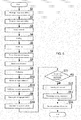
- FIG. 4 is a flowchart showing a process of the image processing apparatus 200 in accordance with the first embodiment.
- a program for executing the flowchart is stored in a program memory of the image processing apparatus 200.
- the image processing apparatus 200 acquires an image of the package 400 from the first image acquisition unit 110 (step S1).
- the distance image generation unit 210 generates a distance image on the basis of a plurality of images received from the second image acquisition unit 120 (step S2).
- the noise removal unit 221 removes noise from the distance image (step S3).
- the scaling unit 222 adjusts the scale in the Z-direction of the distance image from which noise has been removed by the noise removal unit 221, on the basis of the scale in the X-direction and the scale in the Y-direction (step S4).
- the modeling unit 223 calculates the coordinate point in three-dimensional space of each pixel of the package 400, on the basis of the distance image the scale in the Z-direction of which has been adjusted by the scaling unit 222 (step S5).
- the three-dimensional mapping unit 224 generates three-dimensional data on the basis of the set of coordinate points in three-dimensional space calculated by the modeling unit 223, and the image of the package 400 acquired by the first image acquisition unit 110 (step S6).
- the base plane detection unit 231 detects a base plane that serves as a reference for a position of the package 400 (step S7).
- the flattening unit 232 flattens the three-dimensional data generated by the three-dimensional mapping unit 224 with reference to the base plane detected by the base plane detection unit 231, to generate two-dimensional data (step S8).
- the recognition image generation unit 240 generates a recognition image that is used to recognize the address information, on the basis of the two-dimensional data generated by the flattening unit 232 (step S9).
- the recognition unit 250 performs an OCR process on the recognition image generated by the recognition image generation unit 240 (step S10).
- the recognition unit 250 determines whether or not the address information has been successfully recognized (step S11). When the recognition unit 250 determines that the address information has been successfully recognized, the recognition unit 250 shifts processing to step S14 described below. Meanwhile, when the recognition unit 250 determines that the address information has not been successfully recognized, the recognition unit 250 sends a VC request and the recognition image to the VCS 500 through the network NW (step S12). Thereafter, the recognition unit 250 receives address information from the VCS 500 through the network NW (step S13).
- the recognition unit 250 sends the address information successfully recognized in step S11 or the address information received in step S13, to the sorting apparatus 300 (step S14). As a result, the package 400 the address information of which has not been successfully recognized by the recognition unit 250 is classified into a correct sorting destination.
- the image processing apparatus 200 of the first embodiment has the three-dimensional data generation unit 220, the two-dimensional data generation unit 230, and the recognition image generation unit 240.
- the three-dimensional data generation unit 220 generates three-dimensional data of the package 400 on the basis of an image and a distance image of the package 400.
- the two-dimensional data generation unit 230 flattens the three-dimensional data generated by the three-dimensional data generation unit 220 to generate two-dimensional data.
- the recognition image generation unit 240 generates a recognition image that is used to recognize address information, on the basis of the two-dimensional data generated by the two-dimensional data generation unit 230. As a result, the image processing apparatus 200 of the first embodiment can improve the recognition rate of address information attached to the package 400.
- the packaging material of the package 400 is a glossy material, such as a plastic
- the light of the illumination device is specularly reflected by the surface of the packaging material, and therefore, clipping (saturation of the luminance value) occurs in the image of the package 400 acquired by the first image acquisition unit 110. If clipping occurs in the image of the package 400, the address information (object information) may not be successfully recognized. Therefore, an image processing apparatus 200 in accordance with the second embodiment detects a region around the address information where light is reflected, and reduces the reflection of light in two-dimensional data by image processing. As a result, the recognition rate of the address information can be improved.
- the second embodiment will now be described in greater detail.
- FIG. 5 is a block diagram of the image processing apparatus 200 in accordance with the second embodiment.
- the image processing apparatus 200 includes, in addition to the distance image generation unit 210, the three-dimensional data generation unit 220, the two-dimensional data generation unit 230, the recognition image generation unit 240, and the recognition unit 250, a reflection region detection unit 260, and a reflection reduction unit 270.
- the recognition unit 250 sends a VC request to the VCS 500.
- specular reflection clipping
- the recognition unit 250 is likely to falsely recognize an area (edge) where there is a sharp change in luminance due to the specular reflection, as a portion of a character.
- the reflection reduction unit 270 performs a process of reducing specular reflection, in order to improve the recognition rate of the address information.
- the reflection region detection unit 260 excludes a region having a high luminance of a surface facing vertically upward (the Z-direction) where the address information is highly likely to be written, from a region on which the reflection reduction process is to be performed, on the basis of the three-dimensional data of the package 400 generated by the three-dimensional mapping unit 224.
- the reflection region detection unit 260 determines whether or not a surface faces vertically upward (the Z-direction), using a normal vector of the surface.
- the reflection region detection unit 260 identifies a region having a high luminance of a surface other than the surface facing vertically upward (the Z-direction) as a specular reflection region. As a result, the reflection region detection unit 260 can distinguish a blank portion of a region where the address information is written, from a portion in which clipping occurs due to specular reflection, on the basis of the three-dimensional data of the package 400.
- the first image acquisition unit 110 outputs an image of the package 400 to the reflection region detection unit 260.
- the three-dimensional mapping unit 224 outputs three-dimensional data to the reflection region detection unit 260.
- the reflection region detection unit 260 detects a region where light is reflected around the address information, in the image of the package 400. Specifically, the reflection region detection unit 260 detects a region having a saturated luminance value in the image of the package 400 input from the first image acquisition unit 110, as a specular reflection region.
- the reflection region detection unit 260 also excludes a region having a high luminance of a surface facing vertically upward (the Z-direction), from the specular reflection region, on the basis of the three-dimensional data of the package 400 input from the three-dimensional mapping unit 224.
- the reflection region detection unit 260 outputs the detected specular reflection region to the reflection reduction unit 270.
- the reflection reduction unit 270 reduces light reflection in the two-dimensional data generated by the flattening unit 232, by image processing, on the basis of the specular reflection region detected by the reflection region detection unit 260.
- the reflection reduction unit 270 executes an existing algorithm such as inpainting to perform the reflection reduction process on the specular reflection region.
- the reflection reduction unit 270 fills "holes" using surrounding pixels (this process may be referred to as "hole-filling”), to reduce light reflection in the specular reflection region detected by the reflection region detection unit 260.
- the reflection reduction unit 270 may give higher priority to filling "holes" in order to prevent a new edge (an area where there is a sharp change in luminance) from occurring than that to filling "holes" in order to eliminate unnaturalness.
- the reflection reduction unit 270 outputs the two-dimensional data on which the reflection reduction process has been performed, to the recognition image generation unit 240.
- the subsequent steps are similar to those of the first embodiment and will not be described.
- FIG. 6 is a flowchart showing a process of the image processing apparatus 200 in accordance with the second embodiment.
- a program for executing the flowchart is stored in a program memory of the image processing apparatus 200.
- the image processing apparatus 200 acquires an image of the package 400 from the first image acquisition unit 110 (step S1).
- the distance image generation unit 210 generates a distance image on the basis of a plurality of sub-images received from the second image acquisition unit 120 (step S2).
- the noise removal unit 221 removes noise from the distance image (step S3).
- the scaling unit 222 adjusts the scale in the Z-direction of the distance image from which noise has been removed by the noise removal unit 221, on the basis of the scale in the X-direction and the scale in the Y-direction (step S4).
- the modeling unit 223 calculates the coordinate point in three-dimensional space of each pixel of the package 400, on the basis of the distance image the scale in the Z-direction of which has been adjusted by the scaling unit 222 (step S5).
- the three-dimensional mapping unit 224 generates three-dimensional data on the basis of the set of coordinate points in three-dimensional space calculated by the modeling unit 223, and the image of the package 400 acquired by the image acquisition apparatus 100 (step S6).
- the base plane detection unit 231 detects a base plane that serves as a reference for a position of the package 400 (step S7).
- the flattening unit 232 flattens the three-dimensional data generated by the three-dimensional mapping unit 224 with reference to the base plane detected by the base plane detection unit 231, to generate two-dimensional data (step S8).
- the reflection region detection unit 260 detects a specular reflection region where light is reflected around the address information, in the image of the package 400 acquired from the image acquisition apparatus 100 (step S15).
- the reflection reduction unit 270 reduces light reflection in the two-dimensional data generated by the flattening unit 232, by image processing, on the basis of the specular reflection region detected by the reflection region detection unit 260 (step S16).
- the recognition image generation unit 240 generates a recognition image that is used to recognize the address information, on the basis of the two-dimensional data on which the reflection reduction process has been performed by the reflection reduction unit 270 (step S9).
- the recognition unit 250 performs an OCR process on the recognition image generated by the recognition image generation unit 240 (step S10).
- the subsequent steps are similar to those of the first embodiment and will not be described.
- the image processing apparatus 200 of the second embodiment has the reflection region detection unit 260 and the reflection reduction unit 270.
- the reflection region detection unit 260 detects a specular reflection region where light is reflected around the address information, in the image of the package 400.
- the reflection reduction unit 270 reduces light reflection in the two-dimensional data generated by the flattening unit 232, by image processing, on the basis of the specular reflection region detected by the reflection region detection unit 260.
- the image processing apparatus 200 of the second embodiment can have a further improved recognition rate of address information attached to the package 400.
- the second image acquisition unit 120 is a stereo camera, which acquires a plurality of images from different viewpoints.
- the second image acquisition unit 120 is a light-field camera.
- the second image acquisition unit 120 captures an image of the package 400 as it is being moved by the conveyor belt 310.
- the second image acquisition unit 120 acquires not only position information of light rays that are reflected by the package 400 and reach the second image acquisition unit 120, but also information about directions that the light rays travel.
- By performing a predetermined process on the image data (light-field data) acquired by the second image acquisition unit 120 an image can be reconstructed such that a focus is set at an arbitrary position, or a viewpoint is changed.
- the second image acquisition unit 120 is hereinafter referred to as the light-field camera 120.
- FIG. 7 is a diagram showing a detailed configuration of the light-field camera 120 in accordance with the third embodiment.
- the Y-axis is an axis extending in a direction that the package 400 is transported
- the Z-axis is an axis extending in a height direction of the package 400
- the X-axis is an axis extending in a direction perpendicular to the Y-direction and the Z-direction.
- the light-field camera 120 includes a main lens 125, a microlens array 126, and an image sensor 127.
- the main lens 125 receives light from an object (the package 400).
- the microlens array 126 is a lens array including a plurality of microlenses.
- the image sensor 127 which is an image capture device having a plurality of pixels, detects the intensity of light at each pixel.
- the image sensor 127 is, for example, a CCD sensor, a CMOS sensor, etc.
- the light-field camera 120 of FIG. 7 is of the compound eye type, this is not limiting. For example, a similar effect is obtained by light-field cameras of other types, such as the multiple eye type.
- the light-field camera 120 of this embodiment is a virtual image optical system, this is not limiting. For example, a similar effect is obtained by a real image optical system.
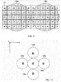
- FIG. 8 is a diagram showing a structure of the microlens array 126 in accordance with the third embodiment.
- the microlens array 126 is a lens array of microlenses arranged in a matrix. Light rays input through the main lens 125 are separated by the microlens array 126 according to the directions of the light rays.
- the microlens array 126 of FIG. 8 has 13 ⁇ 13 microlenses, this is not limiting.
- the microlens has a circular shape as viewed along the optical axis, this is not limiting.
- the microlens may be polygonal (e.g., quadrangular).
- FIG. 9 is a diagram showing a relationship between the microlens array 126 and the image sensor 127 in accordance with the third embodiment. As shown in FIG. 9 , light rays separated by the microlens array 126 are projected onto the image sensor 127 to form circular sub-images 128a and 128b. Although the two sub-images 128a and 128b are shown here for the sake of simplicity, a plurality of sub-images corresponding to a plurality of microlenses are actually projected onto the image sensor 127.
- Image data (light-field data) detected by the image sensor 127 is a set of sub-images formed by the respective microlenses.
- the light-field camera 120 sends the acquired light-field data to the image processing apparatus 200.
- the distance image generation unit 210 of the image processing apparatus 200 generates a distance image on the basis of the light-field data received from the light-field camera 120. A method for generating the distance image will now be described.
- the distance image generation unit 210 calculates a distance between the light-field camera 120 and an object, for each sub-image obtained through a microlens, on the basis of the light-field data. As a result, the distance image generation unit 210 can generate a distance image. In the distance image, for example, the greater the distance, the higher (or lower) the luminance value.
- the distance image generation unit 210 performs template matching on a plurality of adjacent sub-images to calculate a disparity, and on the basis of the calculated disparity, calculates a distance using a stereo image processing algorithm.
- FIG. 10 is a diagram for describing the disparity calculation in accordance with the third embodiment.
- a central microlens 126a is adjacent to microlenses 126b and 126c in the Y-direction.
- the central microlens 126a is also adjacent to microlenses 126d and 126e in the X-direction.
- the distance image generation unit 210 performs template matching on the sub-image that is obtained through the central microlens 126a, and each of four sub-images that are obtained through the four microlenses 126b to 126e, to calculate four disparities.
- the distance image generation unit 210 calculates a disparity D1 on the basis of the sub-image that is obtained through the microlens 126a and the sub-image that is obtained through the microlens 126b.
- the distance image generation unit 210 also calculates a disparity D2 on the basis of the sub-image that is obtained through the microlens 126a and the sub-image that is obtained through the microlens 126c.
- the distance image generation unit 210 also calculates a disparity D3 on the basis of the sub-image that is obtained through the microlens 126a and the sub-image that is obtained through the microlens 126d.
- the distance image generation unit 210 also calculates a disparity D4 on the basis of the sub-image that is obtained through the microlens 126a and the sub-image that is obtained through the microlens 126e.
- the distance image generation unit 210 calculates the distance to the object with respect to the sub-image that is obtained through the central microlens 126a, using a stereo image processing algorithm, on the basis of an average value Dave of the four disparities D1 to D4.
- the distance image generation unit 210 performs the above process for all microlenses, to generate a distance image.
- the distance image generation unit 210 outputs the generated distance image to the noise removal unit 221.
- the distance image generation unit 210 calculates the distance using the average value Dave, this is not limiting.
- the distance image generation unit 210 may select a disparity that can be presumed to be the best, from the four disparities D1 to D4, on the basis of the reliability of the result of template matching, and calculate the distance to the object with respect to the sub-image that is obtained through the central microlens 126a, using a stereo image processing algorithm, on the basis of the selected disparity.
- the distance image generation unit 210 of the third embodiment may generate a distance image on the basis of the image data (light-field data) of the package 400 acquired by the light-field camera 120.
- the recognition rate of the address information attached to the package 400 can be improved.
- the modeling unit 223 may weight distance information contained in the distance image on the basis of the reliability with which the distance image has been acquired (the reliability of the result of template matching), to generate the three-dimensional data. As a result, the modeling unit 223 can generate the three-dimensional data with higher accuracy.
- the light-field camera 120 is used as an area sensor.
- the light-field camera 120 is used as a line sensor. As a result, the configuration of the light-field camera 120 can be simplified.
- the fourth embodiment will now be described in detail.
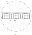
- FIG. 11 is a diagram showing a structure of a microlens array 126 in accordance with the fourth embodiment.
- the microlens array 126 is a lens array of microlenses arranged in a matrix.
- Light rays input through a main lens 125 are separated by the microlens array 126 according to the directions of the light rays.
- the microlens array 126 is longer in the X-direction (longitudinal direction) than in the Y-direction (transverse direction).
- the Y-direction is a direction in which the package 400 is moved by the conveyor belt 310
- the X-direction is perpendicular to the Y-direction.
- the microlens array 126 shown in FIG. 11 has 45 microlenses (3 rows ⁇ 15 columns), this is not limiting.
- Light-field data acquired by the light-field camera 120 which is a set of micro-images obtained through the microlenses, includes more pixels in the X-direction than in the Y-direction.
- the light-field camera 120 outputs a one-dimensional set of pixel values when shooting is performed once.
- the light-field camera 120 performs successive shooting to acquire a two-dimensional image of the package 400 as it is being transported at a constant speed by the conveyor belt 310. Therefore, as shown in FIG. 11 , the microlens array 126 and the image sensor 127 are disposed only within a range necessary for obtaining a line of image.
- the light-field camera 120 is disposed such that the longitudinal direction (the X-direction) of the light-field camera 120 is perpendicular to the movement direction (the Y-direction) of the package 400.
- the microlens has a circular shape as viewed along the optical axis, this is not limiting.
- the microlens may be polygonal (e.g., quadrangular).
- a conventional light-field camera may be employed, and only a portion of the output thereof may be used.
- the area that is illuminated by the illumination devices 130 and 140 can be limited to a linear area.
- the illumination devices 130 and 140 do not need to illuminate a large area, and therefore, the size and cost of the illumination devices 130 and 140 can be reduced.
- the light-field camera 120 can capture an image of each entire package 400. Note that a lens may be provided between the illumination devices 130 and 140 and the package 400 in order to concentrate light to the linear area.
- the distance image generation unit 210 of the fourth embodiment generates a distance image on the basis of the image data (light-field data) of the package 400 acquired by the light-field camera 120 that is used as a line sensor.
- the size and cost of the illumination device can be reduced, and a distance image can be generated irrespective of the shape of the package 400.
- the position of the image acquisition apparatus 100 is fixed, and the package 400 is passed through an image capture position of the image acquisition apparatus 100, this is not limiting.
- the position of the package 400 may be fixed, and the image acquisition apparatus 100 may be moved to capture an image of the package 400.
- both the image acquisition apparatus 100 and the package 400 may be moved such that the image acquisition apparatus 100 captures an image of the object.
- the recognition unit 250 performs a recognition process on a vehicle registration plate of a vehicle that is traveling on a road.
- the recognition unit 250 in accordance with any one of the first to fourth embodiments may be applied to the recognition process of a vehicle registration plate. The fifth embodiment will now be described in detail.
- the image acquisition apparatus 100 is disposed, at the side of a road.
- the first image acquisition unit 110 and the second image acquisition unit 120 capture images of a vehicle registration plate of a vehicle.
- the distance image generation unit 210 generates a distance image on the basis of the images of the vehicle registration plate acquired by the second image acquisition unit 120.
- the three-dimensional data generation unit 220 generates three-dimensional data of the vehicle registration plate on the basis of the image of the vehicle registration plate acquired by the first image acquisition unit 110 and the distance image generated by the distance image generation unit 210.
- the two-dimensional data generation unit 230 flattens the three-dimensional data generated by the three-dimensional data generation unit 220 to generate two-dimensional data.
- the recognition image generation unit 240 generates a recognition image that is used to recognize the vehicle registration plate, on the basis of the two-dimensional data generated by the two-dimensional data generation unit 230. As a result, the recognition rate of number information (object information) written on a vehicle registration plate (object) can be improved.
- the recognition unit 250 performs a recognition process on a traffic sign provided at the side of a road.
- the recognition unit 250 in accordance with any one of the first to fourth embodiment may be applied to the recognition process of a traffic sign.
- the sixth embodiment will now be described in detail.
- the image acquisition apparatus 100 is provided in a vehicle.
- the first image acquisition unit 110 and the second image acquisition unit 120 capture images of a traffic sign.
- the distance image generation unit 210 generates a distance image on the basis of the images of the traffic sign acquired by the second image acquisition unit 120.
- the three-dimensional data generation unit 220 generates three-dimensional data of the traffic sign on the basis of the image of the traffic sign acquired by the first image acquisition unit 110 and the distance image generated by the distance image generation unit 210.
- the two-dimensional data generation unit 230 flattens the three-dimensional data generated by the three-dimensional data generation unit 220 to generate two-dimensional data.
- the recognition image generation unit 240 generates a recognition image that is used to recognize the traffic sign, on the basis of the two-dimensional data generated by the two-dimensional data generation unit 230. As a result, the recognition rate of information (object information) written on a traffic sign (object) can be improved.
- the distance image generation unit 210 generates a distance image on the basis of images captured by a stereo camera or a light-field camera, this is not limiting.
- the second image acquisition unit 120 may be a distance sensor that measures a distance between a reference position and the package 400.
- the distance image generation unit 210 may generate a distance image on the basis of the distance measured by the distance sensor.
- the image processing apparatus 200 includes the recognition unit 250
- the recognition unit 250 may be provided in an OCR apparatus that can communicate with the image processing apparatus 200.
- the image processing apparatus 200 has the three-dimensional data generation unit 220, the two-dimensional data generation unit 230, and the recognition image generation unit 240.
- the three-dimensional data generation unit 220 generates three-dimensional data of the package 400 to which address information is attached, on the basis of an image of the package 400, and a distance image that indicates a distance between a reference position and the package 400 for each pixel.
- the two-dimensional data generation unit 230 flattens the three-dimensional data generated by the three-dimensional data generation unit 220 to generate two-dimensional data.
- the recognition image generation unit 240 generates a recognition image that is used to recognize the address information, on the basis of the two-dimensional data generated by the two-dimensional data generation unit 230. As a result, the recognition rate of the address information (object information) attached to the package 400 (object) can be improved.
- the image processing apparatus 200 of the above embodiments includes a computer system.
- the above steps performed by the image processing apparatus 200 are each stored in the form of a program in a computer-readable storage medium, and performed by a computer reading and executing the program.
- the computer-readable storage medium refers to a magnetic disk, a magneto-optical disk, a CD-ROM, a DVD-ROM, a semiconductor memory, etc.
- the computer program may be distributed to a computer through a communication line, and the computer that has received the computer program may execute the program.
- An image processing apparatus includes:
- An image processing apparatus includes:
Landscapes
- Engineering & Computer Science (AREA)
- Physics & Mathematics (AREA)
- General Physics & Mathematics (AREA)
- Multimedia (AREA)
- Theoretical Computer Science (AREA)
- Computer Vision & Pattern Recognition (AREA)
- General Health & Medical Sciences (AREA)
- Vascular Medicine (AREA)
- Artificial Intelligence (AREA)
- Health & Medical Sciences (AREA)
- Image Processing (AREA)
- Image Analysis (AREA)
- Length Measuring Devices By Optical Means (AREA)
Abstract
Description
- Exemplary embodiments described herein relate to image processing apparatuses, image processing systems, image processing methods, and programs.
- In the field of logistics, the optical character recognition (OCR) apparatus has in recent years been used to recognize a shipping label written on an irregular package. In the case where a package is made of a paper or plastic bag, the package is deformed, depending on the shape of a shipping item, so that a shipping label written on the package is also deformed.
- If the shipping label is not significantly deformed, the OCR apparatus can correct the deformation of an image of the shipping label by image processing to recognize address information written on the shipping label. However, if the shipping label is significantly deformed, the OCR apparatus may falsely recognize or fail to recognize the shipping label.
-
-
FIG. 1 is a diagram showing an overall configuration of animage processing system 10 in accordance with a first embodiment; -
FIG. 2 is a diagram showing an example process of measuring a distance using a secondimage acquisition unit 120 in accordance with the first embodiment; -
FIG. 3 is a block diagram of animage processing apparatus 200 in accordance with the first embodiment; -
FIG. 4 is a flowchart showing a process of theimage processing apparatus 200 in accordance with the first embodiment; -
FIG. 5 is a block diagram of animage processing apparatus 200 in accordance with a second embodiment; -
FIG. 6 is a flowchart showing a process of theimage processing apparatus 200 in accordance with the second embodiment; -
FIG. 7 is a diagram showing a detailed configuration of a light-field camera 120 in accordance with a third embodiment; -
FIG. 8 is a diagram showing a structure of amicrolens array 126 in accordance with the third embodiment; -
FIG. 9 is a diagram showing a relationship between themicrolens array 126 and animage sensor 127 in accordance with the third embodiment; -
FIG. 10 is a diagram for describing disparity calculation in accordance with the third embodiment; and -
FIG. 11 is a diagram showing a structure of amicrolens array 126 in accordance with a fourth embodiment. - An image processing apparatus in accordance with an embodiment has a three-dimensional data generation unit, a two-dimensional data generation unit, and a recognition image generation unit. The three-dimensional data generation unit generates three-dimensional data of an object on the basis of an image of the object on which object information represented by a character or a symbol is attached, and a distance image indicating a distance between a reference position and the object for each pixel. The two-dimensional data generation unit generates two-dimensional data by flattening the three-dimensional data generated by the three-dimensional data generation unit. The recognition image generation unit generates a recognition image which is used to recognize the object information, on the basis of the two-dimensional data generated by the two-dimensional data generation unit.
- Image processing apparatuses, image processing systems, image processing methods, and programs in accordance with embodiments will now be described with reference to the accompanying drawings.
-
FIG. 1 is a diagram showing an overall configuration of animage processing system 10 in accordance with a first embodiment. - As shown in
FIG. 1 , theimage processing system 10 of this embodiment includes animage acquisition apparatus 100, animage processing apparatus 200, asorting apparatus 300, and a video coding system (VCS) 500. - The
image processing apparatus 200 is communicatively coupled to theimage acquisition apparatus 100 and thesorting apparatus 300. Theimage processing apparatus 200 is also coupled to theVCS 500 through a network NW. The network NW is, for example, a wide area network (WAN), a local area network (LAN), etc. - The
image acquisition apparatus 100 includes a firstimage acquisition unit 110, a secondimage acquisition unit 120, anillumination device 130, and an illumination device 140. - The first
image acquisition unit 110 is, for example, a line scan sensor including a linear array of charge-coupled device (CCD) or complementary metal oxide semiconductor (CMOS) sensors. Theillumination devices 130 and 140 illuminate a package (example object) 400 on aconveyor belt 310. The firstimage acquisition unit 110 performs successive shooting to acquire an image of thepackage 400 as it is being transported by theconveyor belt 310 at a constant speed. Theimage acquisition apparatus 100 sends the image of thepackage 400 acquired by the firstimage acquisition unit 110 to theimage processing apparatus 200. -
FIG. 2 is a diagram showing an example process of measuring a distance using the secondimage acquisition unit 120 in accordance with the first embodiment. The secondimage acquisition unit 120 is, for example, a stereo camera, which captures a plurality of images from different viewpoints. The secondimage acquisition unit 120 is used to generate a distance image of thepackage 400. The secondimage acquisition unit 120 includes afirst camera 121 and asecond camera 122. Thefirst camera 121 captures a left image. Thesecond camera 122 captures a right image. - In
FIGS. 1 and2 , the Y-axis is an axis extending in a direction that thepackage 400 is transported. The Z-axis is an axis extending in a height direction of thepackage 400. The X-axis is an axis extending in a direction that is perpendicular to the Y-direction and the Z-direction. A position in the Z-axis direction of a line connecting thefirst camera 121 and thesecond camera 122 is hereinafter referred to as a "reference position." - In
FIG. 2 , aleft image surface 123 and aright image surface 124 are shown. Here, a distance (baseline length) between thefirst camera 121 and thesecond camera 122 is represented by B, a focal length is represented by F, a distance between the reference position and thepackage 400 is represented by DZ, a difference between a position of thepackage 400 in the left image and a center of the left image is represented by DL, and a difference between a position of thepackage 400 in the right image and a center of the right image is represented by DR. - In this case, the disparity d = DL - DR, and the distance DZ = F × B/d. The focal length F is determined by a lens used in the
first camera 121 and thesecond camera 122. The distance B is determined by a position of thefirst camera 121 and a position of thesecond camera 122. The disparity d is calculated by performing template matching on the left image and the right image. - The second
image acquisition unit 120 sends the acquired right and left images to theimage processing apparatus 200. Theimage processing apparatus 200 can generate a distance image of thepackage 400 by calculating the distance DZ for each pixel on the basis of the right and left images received from the secondimage acquisition unit 120. The distance image has a luminance value that increases (or decreases) with an increase in distance, for example. Theimage acquisition apparatus 100 sends the generated distance image to theimage processing apparatus 200. - The
image processing apparatus 200 recognizes address information (object information) written in a shipping label region (a region where the object information is present) 410 of thepackage 400, on the basis of the image of thepackage 400 and the generated distance image received from theimage acquisition apparatus 100. Theimage processing apparatus 200 sends the recognition result (address information) to thesorting apparatus 300. The address information includes, for example, a postal code written in numerals, an address written in characters, numerals, and symbols, or a combination thereof. - The
sorting apparatus 300 includes, for example, a plurality of sorting pockets (not shown) arranged in a plurality of separate stages and a plurality of separate rows, and a VCS pocket (not shown). Thesorting apparatus 300 switches sorting destinations ofpackages 400 transported on theconveyor belt 310, depending on the recognition result (address information) received from theimage processing apparatus 200, so that thepackages 400 are accumulated in their sorting destinations, i.e., sorting pockets. - When the
image processing apparatus 200 has failed to recognize the address information written in theshipping label region 410, theimage processing apparatus 200 sends, to thesorting apparatus 300, a notification indicating the failure to recognize the address information. When thesorting apparatus 300 has received the notification indicating the failure to recognize the address information from theimage processing apparatus 200, thesorting apparatus 300 switches the sorting destination of thepackage 400 to the VCS pocket. - Also, when the
image processing apparatus 200 has failed to recognize the address information written in theshipping label region 410, theimage processing apparatus 200 sends the image data of thepackage 400 and a video coding (VC) request to the VCS 500 through the network NW. - The VCS 500 is a system that displays the image of the
package 400 the address information of which has not been successfully recognized by theimage processing apparatus 200, and assists recognizing the address information by visibility of an operator. TheVCS 500 includes a plurality of terminals. Each terminal displays the image of thepackage 400 on a display device, and receives address information that is input by an operator through an input device, such as a keyboard or a touch panel. - When the
VCS 500 has received address information input by an operator, theVCS 500 sends the input address information to theimage processing apparatus 200 through the network NW. The address information is used when thepackage 400 which is accumulated in the VCS pocket is processed again. As a result, thepackage 400 the address information of which has not been successfully recognized by the OCR process is classified into a correct sorting destination by the reprocess. - Although it is assumed above that the
image processing apparatus 200 generates the distance image, this is not limiting. For example, theimage acquisition apparatus 100 may generate the distance image on the basis of the left and right images acquired by the secondimage acquisition unit 120, and send the generated distance image to theimage processing apparatus 200. -
FIG. 3 is a block diagram of theimage processing apparatus 200 in accordance with the first embodiment. Theimage processing apparatus 200 includes a distanceimage generation unit 210, a three-dimensionaldata generation unit 220, a two-dimensionaldata generation unit 230, a recognitionimage generation unit 240, and arecognition unit 250. - The distance
image generation unit 210, the three-dimensionaldata generation unit 220, the two-dimensionaldata generation unit 230, the recognitionimage generation unit 240, and therecognition unit 250 are implemented by a program stored in a program memory being executed by a processor, such as a central processing unit (CPU). Note that the distanceimage generation unit 210, the three-dimensionaldata generation unit 220, the two-dimensionaldata generation unit 230, the recognitionimage generation unit 240, and therecognition unit 250 may be implemented by hardware, such as a large scale integration (LSI), an application specific integrated circuit (ASIC), or a field-programmable gate array (FPGA), that has a function similar to that which is performed by a processor executing a program. In other words, each of the functions of embodiments is implemented by one or more processing circuits. Alternatively, a plurality of functions of embodiments is implemented by one or more processing circuits. A processing circuit includes a programmed processor as a processor including a circuit. A processing circuit includes devices such as an ASIC, and a commonly used circuit element which is provided to perform a function described herein. - As described above, the distance
image generation unit 210 calculates the distance DZ for each pixel on the basis of the right and left images received from the secondimage acquisition unit 120, to generate the distance image of thepackage 400. The distanceimage generation unit 210 outputs the generated distance image to the three-dimensionaldata generation unit 220. - The three-dimensional
data generation unit 220 includes anoise removal unit 221, ascaling unit 222, amodeling unit 223, and a three-dimensional mapping unit 224. The two-dimensionaldata generation unit 230 includes a baseplane detection unit 231 and aflattening unit 232. - The distance image generated by the distance
image generation unit 210 contains an incorrect value caused by an error in disparity calculation, etc. Therefore, thenoise removal unit 221 removes noise from the distance image input from the distanceimage generation unit 210. For example, thenoise removal unit 221 removes noise using a median filter. Thenoise removal unit 221 outputs the distance image from which noise has been removed, to thescaling unit 222. - The
scaling unit 222 adjusts a scale in the Z-direction (the height direction of the package 400) of the distance image from which noise has been removed by the noise removal unit, on the basis of a scale in the X-direction (a transverse direction of the image of the package 400) and a scale in the Y-direction (a longitudinal direction of the image of the package 400). Thescaling unit 222 outputs the distance image the scale in the Z-direction of which has been adjusted, to themodeling unit 223. - The
modeling unit 223 calculates a coordinate point (x, y, z) in three-dimensional space of each pixel of thepackage 400, on the basis of the distance image the scale in the Z-direction of which has been adjusted by thescaling unit 222. For example, themodeling unit 223 interpolates coordinate points in incomplete portions of the distance image by performing spline interpolation. Themodeling unit 223 outputs a set of calculated coordinate points (a three-dimensional model) in three-dimensional space to the three-dimensional mapping unit 224. - The three-
dimensional mapping unit 224 generates three-dimensional data on the basis of the set of coordinate points in three-dimensional space calculated by themodeling unit 223, and the image of thepackage 400 received from the firstimage acquisition unit 110. Specifically, the three-dimensional mapping unit 224 associates the coordinate point (x, y, z) in three-dimensional space of each pixel of thepackage 400 with a luminance value on the basis of the image of thepackage 400 received from the firstimage acquisition unit 110, to generate three-dimensional data of thepackage 400. The three-dimensional mapping unit 224 outputs the generated three-dimensional data to the baseplane detection unit 231. - The base
plane detection unit 231 detects a base plane that is a reference for a position of thepackage 400. For example, the base plane is a plane on which thepackage 400 is placed. For example, the baseplane detection unit 231 detects the base plane by executing a random sample consensus (RANSAC) algorithm on the three-dimensional data generated by the three-dimensional mapping unit 224. In the case where the position of theconveyor belt 310 and the position of the secondimage acquisition unit 120 are fixed, the baseplane detection unit 231 may detect the base plane only once. The baseplane detection unit 231 outputs data of the detected base plane and the three-dimensional data to theflattening unit 232. - The flattening
unit 232 flattens the three-dimensional data generated by the three-dimensional mapping unit 224 with reference to the base plane detected by the baseplane detection unit 231, to generate two-dimensional data. Specifically, the flatteningunit 232 lowers the coordinate in the Z-direction of each point of the three-dimensional data to the height of the base plane while maintaining the distance between each point. The three-dimensional data is eventually stretched, so that a surface on which the deformed address information (object information) is written is flattened. As a result, the deformation of the address information (object information) is corrected. The flatteningunit 232 outputs the generated two-dimensional data to the recognitionimage generation unit 240. - All of the coordinate points in three-dimensional space are moved to the base plane, and therefore, the number of coordinate points per unit area is sparse in some areas, and dense in others, in the two-dimensional data generated by the flattening
unit 232. Therefore, the two-dimensional data generated by the flatteningunit 232 should be corrected to generate an image suited to recognition of the address information (object information). - Therefore, the recognition
image generation unit 240 generates a recognition image that is used to recognize the address information (object information) on the basis of the two-dimensional data generated by the flatteningunit 232. Specifically, the recognitionimage generation unit 240 calculates the luminance of each pixel indicated by a two-dimensional grid point, to generate the recognition image. - The recognition
image generation unit 240 may also perform a super-resolution imaging process on the two-dimensional data generated by the flatteningunit 232 in order to enhance the resolution of the two-dimensional data. For example, the recognitionimage generation unit 240 may perform, on the two-dimensional data, a super-resolution imaging process of producing an initial image by nearest neighbor search, and using self-similarity. As a result, the recognition rate of the address information can be improved. - The
recognition unit 250 performs a recognition process on a binarized image. Therefore, the recognitionimage generation unit 240 performs a super-resolution imaging process on the two-dimensional data to generate a binarized image having a super resolution as a recognition image. The recognitionimage generation unit 240 outputs the generated recognition image to therecognition unit 250. - The
recognition unit 250 performs an OCR process on the recognition image generated by the recognitionimage generation unit 240. When therecognition unit 250 has successfully detected character information in theshipping label region 410, therecognition unit 250 can successfully recognize the address information. Meanwhile, when therecognition unit 250 has failed to detect character information in theshipping label region 410, therecognition unit 250 cannot successfully recognize the address information. - When the
recognition unit 250 has successfully recognized the address information, therecognition unit 250 sends the recognized address information to thesorting apparatus 300. Meanwhile, when therecognition unit 250 has failed to recognize the address information, therecognition unit 250 sends a VC request and the recognition image to theVCS 500 through the network NW. - When the
VCS 500 has received the VC request from therecognition unit 250, theVCS 500 displays the recognition image received from therecognition unit 250 on a display device. When an operator has input address information to theVCS 500, theVCS 500 sends the input address information to therecognition unit 250 through the network NW. Therecognition unit 250 sends the address information received from theVCS 500 to thesorting apparatus 300. As a result, thepackage 400 the address information of which has not been successfully recognized by therecognition unit 250 is classified into a correct sorting destination. -
FIG. 4 is a flowchart showing a process of theimage processing apparatus 200 in accordance with the first embodiment. A program for executing the flowchart is stored in a program memory of theimage processing apparatus 200. - Initially, the
image processing apparatus 200 acquires an image of thepackage 400 from the first image acquisition unit 110 (step S1). The distanceimage generation unit 210 generates a distance image on the basis of a plurality of images received from the second image acquisition unit 120 (step S2). Next, thenoise removal unit 221 removes noise from the distance image (step S3). Thescaling unit 222 adjusts the scale in the Z-direction of the distance image from which noise has been removed by thenoise removal unit 221, on the basis of the scale in the X-direction and the scale in the Y-direction (step S4). - The
modeling unit 223 calculates the coordinate point in three-dimensional space of each pixel of thepackage 400, on the basis of the distance image the scale in the Z-direction of which has been adjusted by the scaling unit 222 (step S5). The three-dimensional mapping unit 224 generates three-dimensional data on the basis of the set of coordinate points in three-dimensional space calculated by themodeling unit 223, and the image of thepackage 400 acquired by the first image acquisition unit 110 (step S6). - The base
plane detection unit 231 detects a base plane that serves as a reference for a position of the package 400 (step S7). The flatteningunit 232 flattens the three-dimensional data generated by the three-dimensional mapping unit 224 with reference to the base plane detected by the baseplane detection unit 231, to generate two-dimensional data (step S8). - The recognition
image generation unit 240 generates a recognition image that is used to recognize the address information, on the basis of the two-dimensional data generated by the flattening unit 232 (step S9). Therecognition unit 250 performs an OCR process on the recognition image generated by the recognition image generation unit 240 (step S10). - Next, the
recognition unit 250 determines whether or not the address information has been successfully recognized (step S11). When therecognition unit 250 determines that the address information has been successfully recognized, therecognition unit 250 shifts processing to step S14 described below. Meanwhile, when therecognition unit 250 determines that the address information has not been successfully recognized, therecognition unit 250 sends a VC request and the recognition image to theVCS 500 through the network NW (step S12). Thereafter, therecognition unit 250 receives address information from theVCS 500 through the network NW (step S13). - The
recognition unit 250 sends the address information successfully recognized in step S11 or the address information received in step S13, to the sorting apparatus 300 (step S14). As a result, thepackage 400 the address information of which has not been successfully recognized by therecognition unit 250 is classified into a correct sorting destination. - As described above, the
image processing apparatus 200 of the first embodiment has the three-dimensionaldata generation unit 220, the two-dimensionaldata generation unit 230, and the recognitionimage generation unit 240. The three-dimensionaldata generation unit 220 generates three-dimensional data of thepackage 400 on the basis of an image and a distance image of thepackage 400. The two-dimensionaldata generation unit 230 flattens the three-dimensional data generated by the three-dimensionaldata generation unit 220 to generate two-dimensional data. The recognitionimage generation unit 240 generates a recognition image that is used to recognize address information, on the basis of the two-dimensional data generated by the two-dimensionaldata generation unit 230. As a result, theimage processing apparatus 200 of the first embodiment can improve the recognition rate of address information attached to thepackage 400. - Next, a second embodiment will be described. When the packaging material of the
package 400 is a glossy material, such as a plastic, the light of the illumination device is specularly reflected by the surface of the packaging material, and therefore, clipping (saturation of the luminance value) occurs in the image of thepackage 400 acquired by the firstimage acquisition unit 110. If clipping occurs in the image of thepackage 400, the address information (object information) may not be successfully recognized. Therefore, animage processing apparatus 200 in accordance with the second embodiment detects a region around the address information where light is reflected, and reduces the reflection of light in two-dimensional data by image processing. As a result, the recognition rate of the address information can be improved. The second embodiment will now be described in greater detail. -
FIG. 5 is a block diagram of theimage processing apparatus 200 in accordance with the second embodiment. InFIG. 5 , parts corresponding to those ofFIG. 3 are designated by the same reference numerals and will not be described. Theimage processing apparatus 200 includes, in addition to the distanceimage generation unit 210, the three-dimensionaldata generation unit 220, the two-dimensionaldata generation unit 230, the recognitionimage generation unit 240, and therecognition unit 250, a reflectionregion detection unit 260, and areflection reduction unit 270. - When specular reflection occurs on the address information (object information), the address information cannot be reproduced, and therefore, the
recognition unit 250 sends a VC request to theVCS 500. Meanwhile, when specular reflection (clipping) occurs in an image around the address information, therecognition unit 250 is likely to falsely recognize an area (edge) where there is a sharp change in luminance due to the specular reflection, as a portion of a character. In this case, thereflection reduction unit 270 performs a process of reducing specular reflection, in order to improve the recognition rate of the address information. - When the
reflection reduction unit 270 performs the specular reflection reduction process on a region where the address information is written, the recognition rate of the address information undesirably decreases. Therefore, the reflectionregion detection unit 260 excludes a region having a high luminance of a surface facing vertically upward (the Z-direction) where the address information is highly likely to be written, from a region on which the reflection reduction process is to be performed, on the basis of the three-dimensional data of thepackage 400 generated by the three-dimensional mapping unit 224. - The reflection
region detection unit 260 determines whether or not a surface faces vertically upward (the Z-direction), using a normal vector of the surface. The reflectionregion detection unit 260 identifies a region having a high luminance of a surface other than the surface facing vertically upward (the Z-direction) as a specular reflection region. As a result, the reflectionregion detection unit 260 can distinguish a blank portion of a region where the address information is written, from a portion in which clipping occurs due to specular reflection, on the basis of the three-dimensional data of thepackage 400. - As shown in
FIG. 5 , the firstimage acquisition unit 110 outputs an image of thepackage 400 to the reflectionregion detection unit 260. The three-dimensional mapping unit 224 outputs three-dimensional data to the reflectionregion detection unit 260. The reflectionregion detection unit 260 detects a region where light is reflected around the address information, in the image of thepackage 400. Specifically, the reflectionregion detection unit 260 detects a region having a saturated luminance value in the image of thepackage 400 input from the firstimage acquisition unit 110, as a specular reflection region. - The reflection
region detection unit 260 also excludes a region having a high luminance of a surface facing vertically upward (the Z-direction), from the specular reflection region, on the basis of the three-dimensional data of thepackage 400 input from the three-dimensional mapping unit 224. The reflectionregion detection unit 260 outputs the detected specular reflection region to thereflection reduction unit 270. - The
reflection reduction unit 270 reduces light reflection in the two-dimensional data generated by the flatteningunit 232, by image processing, on the basis of the specular reflection region detected by the reflectionregion detection unit 260. For example, thereflection reduction unit 270 executes an existing algorithm such as inpainting to perform the reflection reduction process on the specular reflection region. In inpainting, thereflection reduction unit 270 fills "holes" using surrounding pixels (this process may be referred to as "hole-filling"), to reduce light reflection in the specular reflection region detected by the reflectionregion detection unit 260. Thereflection reduction unit 270 may give higher priority to filling "holes" in order to prevent a new edge (an area where there is a sharp change in luminance) from occurring than that to filling "holes" in order to eliminate unnaturalness. - The
reflection reduction unit 270 outputs the two-dimensional data on which the reflection reduction process has been performed, to the recognitionimage generation unit 240. The subsequent steps are similar to those of the first embodiment and will not be described. -
FIG. 6 is a flowchart showing a process of theimage processing apparatus 200 in accordance with the second embodiment. A program for executing the flowchart is stored in a program memory of theimage processing apparatus 200. - Initially, the
image processing apparatus 200 acquires an image of thepackage 400 from the first image acquisition unit 110 (step S1). The distanceimage generation unit 210 generates a distance image on the basis of a plurality of sub-images received from the second image acquisition unit 120 (step S2). Next, thenoise removal unit 221 removes noise from the distance image (step S3). Thescaling unit 222 adjusts the scale in the Z-direction of the distance image from which noise has been removed by thenoise removal unit 221, on the basis of the scale in the X-direction and the scale in the Y-direction (step S4). - The
modeling unit 223 calculates the coordinate point in three-dimensional space of each pixel of thepackage 400, on the basis of the distance image the scale in the Z-direction of which has been adjusted by the scaling unit 222 (step S5). The three-dimensional mapping unit 224 generates three-dimensional data on the basis of the set of coordinate points in three-dimensional space calculated by themodeling unit 223, and the image of thepackage 400 acquired by the image acquisition apparatus 100 (step S6). - The base
plane detection unit 231 detects a base plane that serves as a reference for a position of the package 400 (step S7). The flatteningunit 232 flattens the three-dimensional data generated by the three-dimensional mapping unit 224 with reference to the base plane detected by the baseplane detection unit 231, to generate two-dimensional data (step S8). - The reflection
region detection unit 260 detects a specular reflection region where light is reflected around the address information, in the image of thepackage 400 acquired from the image acquisition apparatus 100 (step S15). Thereflection reduction unit 270 reduces light reflection in the two-dimensional data generated by the flatteningunit 232, by image processing, on the basis of the specular reflection region detected by the reflection region detection unit 260 (step S16). - The recognition
image generation unit 240 generates a recognition image that is used to recognize the address information, on the basis of the two-dimensional data on which the reflection reduction process has been performed by the reflection reduction unit 270 (step S9). Therecognition unit 250 performs an OCR process on the recognition image generated by the recognition image generation unit 240 (step S10). The subsequent steps are similar to those of the first embodiment and will not be described. - As described above, the
image processing apparatus 200 of the second embodiment has the reflectionregion detection unit 260 and thereflection reduction unit 270. The reflectionregion detection unit 260 detects a specular reflection region where light is reflected around the address information, in the image of thepackage 400. Thereflection reduction unit 270 reduces light reflection in the two-dimensional data generated by the flatteningunit 232, by image processing, on the basis of the specular reflection region detected by the reflectionregion detection unit 260. As a result, theimage processing apparatus 200 of the second embodiment can have a further improved recognition rate of address information attached to thepackage 400. - Next, a third embodiment will be described. In the first and second embodiments, the second
image acquisition unit 120 is a stereo camera, which acquires a plurality of images from different viewpoints. In contrast to this, in the third embodiment, the secondimage acquisition unit 120 is a light-field camera. The third embodiment will now be described in detail. - The second image acquisition unit (light-field camera) 120 captures an image of the
package 400 as it is being moved by theconveyor belt 310. The secondimage acquisition unit 120 acquires not only position information of light rays that are reflected by thepackage 400 and reach the secondimage acquisition unit 120, but also information about directions that the light rays travel. By performing a predetermined process on the image data (light-field data) acquired by the secondimage acquisition unit 120, an image can be reconstructed such that a focus is set at an arbitrary position, or a viewpoint is changed. The secondimage acquisition unit 120 is hereinafter referred to as the light-field camera 120. -
FIG. 7 is a diagram showing a detailed configuration of the light-field camera 120 in accordance with the third embodiment. InFIG. 7 , the Y-axis is an axis extending in a direction that thepackage 400 is transported, the Z-axis is an axis extending in a height direction of thepackage 400, and the X-axis is an axis extending in a direction perpendicular to the Y-direction and the Z-direction. - The light-
field camera 120 includes amain lens 125, amicrolens array 126, and animage sensor 127. Themain lens 125 receives light from an object (the package 400). Themicrolens array 126 is a lens array including a plurality of microlenses. Theimage sensor 127, which is an image capture device having a plurality of pixels, detects the intensity of light at each pixel. Theimage sensor 127 is, for example, a CCD sensor, a CMOS sensor, etc. - Although the light-
field camera 120 ofFIG. 7 is of the compound eye type, this is not limiting. For example, a similar effect is obtained by light-field cameras of other types, such as the multiple eye type. Although the light-field camera 120 of this embodiment is a virtual image optical system, this is not limiting. For example, a similar effect is obtained by a real image optical system. -
FIG. 8 is a diagram showing a structure of themicrolens array 126 in accordance with the third embodiment. As shown inFIG. 8 , themicrolens array 126 is a lens array of microlenses arranged in a matrix. Light rays input through themain lens 125 are separated by themicrolens array 126 according to the directions of the light rays. Although themicrolens array 126 ofFIG. 8 has 13 × 13 microlenses, this is not limiting. - Although, in this embodiment, the microlens has a circular shape as viewed along the optical axis, this is not limiting. For example, the microlens may be polygonal (e.g., quadrangular).
-
FIG. 9 is a diagram showing a relationship between themicrolens array 126 and theimage sensor 127 in accordance with the third embodiment. As shown inFIG. 9 , light rays separated by themicrolens array 126 are projected onto theimage sensor 127 to form circular sub-images 128a and 128b. Although the two sub-images 128a and 128b are shown here for the sake of simplicity, a plurality of sub-images corresponding to a plurality of microlenses are actually projected onto theimage sensor 127. - When the sub-images projected from the
microlens array 126 are received by a plurality of pixels of theimage sensor 127, the intensity of a light ray can be detected for each incident direction. Image data (light-field data) detected by theimage sensor 127 is a set of sub-images formed by the respective microlenses. - The light-
field camera 120 sends the acquired light-field data to theimage processing apparatus 200. The distanceimage generation unit 210 of theimage processing apparatus 200 generates a distance image on the basis of the light-field data received from the light-field camera 120. A method for generating the distance image will now be described. - The distance
image generation unit 210 calculates a distance between the light-field camera 120 and an object, for each sub-image obtained through a microlens, on the basis of the light-field data. As a result, the distanceimage generation unit 210 can generate a distance image. In the distance image, for example, the greater the distance, the higher (or lower) the luminance value. The distanceimage generation unit 210 performs template matching on a plurality of adjacent sub-images to calculate a disparity, and on the basis of the calculated disparity, calculates a distance using a stereo image processing algorithm. -
FIG. 10 is a diagram for describing the disparity calculation in accordance with the third embodiment. Acentral microlens 126a is adjacent to microlenses 126b and 126c in the Y-direction. Thecentral microlens 126a is also adjacent to microlenses 126d and 126e in the X-direction. - The process of calculating a distance between the light-
field camera 120 and an object with respect to a sub-image that is obtained through thecentral microlens 126a, will be specifically described. The distanceimage generation unit 210 performs template matching on the sub-image that is obtained through thecentral microlens 126a, and each of four sub-images that are obtained through the fourmicrolenses 126b to 126e, to calculate four disparities. - Specifically, the distance
image generation unit 210 calculates a disparity D1 on the basis of the sub-image that is obtained through the microlens 126a and the sub-image that is obtained through themicrolens 126b. The distanceimage generation unit 210 also calculates a disparity D2 on the basis of the sub-image that is obtained through the microlens 126a and the sub-image that is obtained through themicrolens 126c. The distanceimage generation unit 210 also calculates a disparity D3 on the basis of the sub-image that is obtained through the microlens 126a and the sub-image that is obtained through themicrolens 126d. The distanceimage generation unit 210 also calculates a disparity D4 on the basis of the sub-image that is obtained through the microlens 126a and the sub-image that is obtained through the microlens 126e. - Next, the distance
image generation unit 210 calculates the distance to the object with respect to the sub-image that is obtained through thecentral microlens 126a, using a stereo image processing algorithm, on the basis of an average value Dave of the four disparities D1 to D4. The distanceimage generation unit 210 performs the above process for all microlenses, to generate a distance image. The distanceimage generation unit 210 outputs the generated distance image to thenoise removal unit 221. - Although it is assumed that the distance
image generation unit 210 calculates the distance using the average value Dave, this is not limiting. For example, the distanceimage generation unit 210 may select a disparity that can be presumed to be the best, from the four disparities D1 to D4, on the basis of the reliability of the result of template matching, and calculate the distance to the object with respect to the sub-image that is obtained through thecentral microlens 126a, using a stereo image processing algorithm, on the basis of the selected disparity. - As described above, the distance
image generation unit 210 of the third embodiment may generate a distance image on the basis of the image data (light-field data) of thepackage 400 acquired by the light-field camera 120. As a result, also in the third embodiment, the recognition rate of the address information attached to thepackage 400 can be improved. - Note that the
modeling unit 223 may weight distance information contained in the distance image on the basis of the reliability with which the distance image has been acquired (the reliability of the result of template matching), to generate the three-dimensional data. As a result, themodeling unit 223 can generate the three-dimensional data with higher accuracy. - Next, a fourth embodiment will be described. In the third embodiment, the light-
field camera 120 is used as an area sensor. In contrast to this, in the fourth embodiment, the light-field camera 120 is used as a line sensor. As a result, the configuration of the light-field camera 120 can be simplified. The fourth embodiment will now be described in detail. -
FIG. 11 is a diagram showing a structure of amicrolens array 126 in accordance with the fourth embodiment. As shown inFIG. 11 , themicrolens array 126 is a lens array of microlenses arranged in a matrix. Light rays input through amain lens 125 are separated by themicrolens array 126 according to the directions of the light rays. - The
microlens array 126 is longer in the X-direction (longitudinal direction) than in the Y-direction (transverse direction). Here, the Y-direction is a direction in which thepackage 400 is moved by theconveyor belt 310, and the X-direction is perpendicular to the Y-direction. Although themicrolens array 126 shown inFIG. 11 has 45 microlenses (3 rows × 15 columns), this is not limiting. - While the
package 400 is being moved in the Y-direction relative to the light-field camera 120, an image of thepackage 400 is captured by the light-field camera 120. Light-field data acquired by the light-field camera 120, which is a set of micro-images obtained through the microlenses, includes more pixels in the X-direction than in the Y-direction. - The light-
field camera 120 outputs a one-dimensional set of pixel values when shooting is performed once. The light-field camera 120 performs successive shooting to acquire a two-dimensional image of thepackage 400 as it is being transported at a constant speed by theconveyor belt 310. Therefore, as shown inFIG. 11 , themicrolens array 126 and theimage sensor 127 are disposed only within a range necessary for obtaining a line of image. - The light-
field camera 120 is disposed such that the longitudinal direction (the X-direction) of the light-field camera 120 is perpendicular to the movement direction (the Y-direction) of thepackage 400. Although, in this embodiment, the microlens has a circular shape as viewed along the optical axis, this is not limiting. For example, the microlens may be polygonal (e.g., quadrangular). Instead of using the light-field camera 120 of this embodiment, a conventional light-field camera may be employed, and only a portion of the output thereof may be used. - When the light-
field camera 120 of this embodiment is used, the area that is illuminated by theillumination devices 130 and 140 can be limited to a linear area. Theillumination devices 130 and 140 do not need to illuminate a large area, and therefore, the size and cost of theillumination devices 130 and 140 can be reduced. In addition, even whenpackages 400 are continuously transported, overlapping each other, or when apackage 400 has an elongated shape in the movement direction, the light-field camera 120 can capture an image of eachentire package 400. Note that a lens may be provided between theillumination devices 130 and 140 and thepackage 400 in order to concentrate light to the linear area. - As described above, the distance
image generation unit 210 of the fourth embodiment generates a distance image on the basis of the image data (light-field data) of thepackage 400 acquired by the light-field camera 120 that is used as a line sensor. As a result, in the fourth embodiment, the size and cost of the illumination device can be reduced, and a distance image can be generated irrespective of the shape of thepackage 400. - Although it is assumed in the first to fourth embodiments that the position of the
image acquisition apparatus 100 is fixed, and thepackage 400 is passed through an image capture position of theimage acquisition apparatus 100, this is not limiting. For example, the position of thepackage 400 may be fixed, and theimage acquisition apparatus 100 may be moved to capture an image of thepackage 400. Alternatively, both theimage acquisition apparatus 100 and thepackage 400 may be moved such that theimage acquisition apparatus 100 captures an image of the object. - Although, in the first to fourth embodiments, address information attached to the
shipping label region 410 is recognized, the object to be recognized is not limited to this. For example, in a fifth embodiment, therecognition unit 250 performs a recognition process on a vehicle registration plate of a vehicle that is traveling on a road. Therecognition unit 250 in accordance with any one of the first to fourth embodiments may be applied to the recognition process of a vehicle registration plate. The fifth embodiment will now be described in detail. - In the fifth embodiment, the
image acquisition apparatus 100 is disposed, at the side of a road. The firstimage acquisition unit 110 and the secondimage acquisition unit 120 capture images of a vehicle registration plate of a vehicle. The distanceimage generation unit 210 generates a distance image on the basis of the images of the vehicle registration plate acquired by the secondimage acquisition unit 120. - The three-dimensional
data generation unit 220 generates three-dimensional data of the vehicle registration plate on the basis of the image of the vehicle registration plate acquired by the firstimage acquisition unit 110 and the distance image generated by the distanceimage generation unit 210. The two-dimensionaldata generation unit 230 flattens the three-dimensional data generated by the three-dimensionaldata generation unit 220 to generate two-dimensional data. - The recognition
image generation unit 240 generates a recognition image that is used to recognize the vehicle registration plate, on the basis of the two-dimensional data generated by the two-dimensionaldata generation unit 230. As a result, the recognition rate of number information (object information) written on a vehicle registration plate (object) can be improved. - In a sixth embodiment, the
recognition unit 250 performs a recognition process on a traffic sign provided at the side of a road. Therecognition unit 250 in accordance with any one of the first to fourth embodiment may be applied to the recognition process of a traffic sign. The sixth embodiment will now be described in detail. - In the sixth embodiment, the
image acquisition apparatus 100 is provided in a vehicle. The firstimage acquisition unit 110 and the secondimage acquisition unit 120 capture images of a traffic sign. The distanceimage generation unit 210 generates a distance image on the basis of the images of the traffic sign acquired by the secondimage acquisition unit 120. - The three-dimensional
data generation unit 220 generates three-dimensional data of the traffic sign on the basis of the image of the traffic sign acquired by the firstimage acquisition unit 110 and the distance image generated by the distanceimage generation unit 210. The two-dimensionaldata generation unit 230 flattens the three-dimensional data generated by the three-dimensionaldata generation unit 220 to generate two-dimensional data. - The recognition
image generation unit 240 generates a recognition image that is used to recognize the traffic sign, on the basis of the two-dimensional data generated by the two-dimensionaldata generation unit 230. As a result, the recognition rate of information (object information) written on a traffic sign (object) can be improved. - Although it is assumed in the first to sixth embodiments that the distance
image generation unit 210 generates a distance image on the basis of images captured by a stereo camera or a light-field camera, this is not limiting. For example, the secondimage acquisition unit 120 may be a distance sensor that measures a distance between a reference position and thepackage 400. In this case, the distanceimage generation unit 210 may generate a distance image on the basis of the distance measured by the distance sensor. - Although it is assumed in the first to sixth embodiments that the
image processing apparatus 200 includes therecognition unit 250, this is not limiting. For example, therecognition unit 250 may be provided in an OCR apparatus that can communicate with theimage processing apparatus 200. - According to at least one of the above embodiments, the
image processing apparatus 200 has the three-dimensionaldata generation unit 220, the two-dimensionaldata generation unit 230, and the recognitionimage generation unit 240. The three-dimensionaldata generation unit 220 generates three-dimensional data of thepackage 400 to which address information is attached, on the basis of an image of thepackage 400, and a distance image that indicates a distance between a reference position and thepackage 400 for each pixel. The two-dimensionaldata generation unit 230 flattens the three-dimensional data generated by the three-dimensionaldata generation unit 220 to generate two-dimensional data. The recognitionimage generation unit 240 generates a recognition image that is used to recognize the address information, on the basis of the two-dimensional data generated by the two-dimensionaldata generation unit 230. As a result, the recognition rate of the address information (object information) attached to the package 400 (object) can be improved. - Note that the
image processing apparatus 200 of the above embodiments includes a computer system. The above steps performed by theimage processing apparatus 200 are each stored in the form of a program in a computer-readable storage medium, and performed by a computer reading and executing the program. Here, the computer-readable storage medium refers to a magnetic disk, a magneto-optical disk, a CD-ROM, a DVD-ROM, a semiconductor memory, etc. Alternatively, the computer program may be distributed to a computer through a communication line, and the computer that has received the computer program may execute the program. - The above embodiments may be expressed as follows.
- An image processing apparatus includes:
- a storage unit configured to store information;
- a hardware processor configured to execute a program stored in the storage unit,
- generating three-dimensional data of an object on the basis of an image of the object on which object information represented by a character or a symbol is attached, and a distance image indicating a distance between a reference position and the object for each pixel,
- flattening the three-dimensional data to generate two-dimensional data, and
- generating a recognition image which is used to recognize the object information, on the basis of the two-dimensional data.
- The above embodiments may also be expressed as follows.
- An image processing apparatus includes:
- a storage unit configured to store information;
- a processor configured to execute a program stored in the storage unit,
- a three-dimensional data generation unit configured to generate three-dimensional data of an object on the basis of an image of the object on which object information represented by a character or a symbol is attached, and a distance image indicating a distance between a reference position and the object for each pixel,
- a two-dimensional data generation unit configured to flatten the three-dimensional data generated by the three-dimensional data generation unit to generate two-dimensional data, and
- a recognition image generation unit configured to generate a recognition image which is used to recognize the object information, on the basis of the two-dimensional data generated by the two-dimensional data generation unit.
- While several exemplary embodiments have been described, these exemplary embodiments are merely for illustrative purposes, and are in no way intended to limit the scope of the invention. These embodiments can be implemented in various other forms. Various omissions, substitutions, and changes can be made to these embodiments without departing the scope and spirit of the invention. These embodiments and their modifications are encompassed by the scope and spirit of the invention, and also by the scope of the invention set forth in the claims and their equivalents.
the storage unit stores the program which causes the hardware processor to execute
the processor executes the program to function as
Claims (15)
- An image processing apparatus comprising:a processing circuit to function asa three-dimensional data generation unit (220) configured to generate three-dimensional data of an object on the basis of an image of the object on which object information represented by a character or a symbol is attached, and a distance image indicating a distance between a reference position and the object for each pixel,a two-dimensional data generation unit (230) configured to flatten the three-dimensional data generated by the three-dimensional data generation unit (220) to generate two-dimensional data, anda recognition image generation unit (240) configured to generate a recognition image which is used to recognize the object information, on the basis of the two-dimensional data generated by the two-dimensional data generation unit (230).
- The image processing apparatus according to claim 1, wherein
the three-dimensional data generation unit (220) includesa noise removal unit (221) configured to remove noise from the distance image (221),a scaling unit (222) configured to adjust a scale in a height direction of the object in the distance image from which the noise has been removed by the noise removal unit (221), on the basis of a scale in a transverse direction of the image of the object and a scale in a longitudinal direction of the image of the object,a modeling unit (223) configured to calculate coordinates in three-dimensional space of each pixel of the object, on the basis of the distance image for which the scale in the height direction of the object has been adjusted by the scaling unit (222), anda three-dimensional mapping unit (224) configured to generate the three-dimensional data on the basis of the coordinates in three-dimensional space calculated by the modeling unit (223), and the image of the object. - The image processing apparatus according to claim 2, wherein
the modeling unit (223) weights distance information contained in the distance image on the basis of reliability with which the distance image has been acquired, to generate the three-dimensional data. - The image processing apparatus according to any one of claims 1 to 3, wherein
the two-dimensional data generation unit (230) includesa base plane detection unit (231) configured to detect a base plane which is a reference to a position of the object, anda flattening unit (232) configured to flatten the three-dimensional data generated by the three-dimensional data generation unit (220), with reference to the base plane detected by the base plane detection unit(231), to generate the two-dimensional data. - The image processing apparatus according to claim 4, wherein
the flattening unit (232) lowers the coordinate in a height direction of each point in the three-dimensional data to a height of the base plane while maintaining a distance between each point. - The image processing apparatus according to any one of claims 1 to 5, wherein
the recognition image generation unit (240) performs a super-resolution imaging process for enhancing a resolution on the two-dimensional data generated by the two-dimensional data generation unit (230). - The image processing apparatus according to claim 6, wherein
the recognition image generation unit (240) performs, on the two-dimensional data, the super-resolution imaging process in which self-similarity is used. - The image processing apparatus according to claim 6, wherein
the recognition image generation unit (240) performs, on the two-dimensional data, the super-resolution imaging process in which an initial image is generated by nearest neighbor search. - The image processing apparatus according to claim 6, wherein
the recognition image generation unit (240) performs the super-resolution imaging process on the two-dimensional data, to generate a binarized image having an enhanced resolution as the recognition image. - The image processing apparatus according to any one of claims 1 to 9, further comprising:a reflection region detection unit (260) configured to detect a region around the object information where light is reflected, in the image of the object; anda reflection reduction unit (270) configured to reduce the light reflection in the two-dimensional data generated by the two-dimensional data generation unit, by image processing, on the basis of the region detected by the reflection region detection unit.
- The image processing apparatus according to claim 10, wherein
the reflection region detection unit (260) distinguishes a blank portion of the region where the object information is written, from a portion in which clipping occurs due to specular reflection, on the basis of the three-dimensional data. - The image processing apparatus according to claim 10 or claim 11, wherein
the reflection reduction unit (270) reduces the light reflection in the region detected by the reflection region detection unit (260), by performing hole-filling using surrounding pixels by inpainting. - An image processing system comprising:the image processing apparatus (200) according to any one of claims 1 to 12; andan image acquisition apparatus (100) to acquire images of the object.
- An image processing method comprising:generating three-dimensional data of an object on the basis of an image of the object on which object information represented by a character or a symbol is attached, and a distance image indicating a distance between a reference position and the object for each pixel;flattening the three-dimensional data to generate two-dimensional data; andgenerating a recognition image which is used to recognize the object information, on the basis of the two-dimensional data.
- A program causing a computer to execute:generating three-dimensional data of an object on the basis of an image of the object on which object information represented by a character or a symbol is attached, and a distance image indicating a distance between a reference position and the object for each pixel;flattening the three-dimensional data to generate two-dimensional data; andgenerating a recognition image which is used to recognize the object information, on the basis of the two-dimensional data.
Applications Claiming Priority (1)
| Application Number | Priority Date | Filing Date | Title |
|---|---|---|---|
| JP2017050498A JP6837880B2 (en) | 2017-03-15 | 2017-03-15 | Image processing equipment, image processing systems, image processing methods, and programs |
Publications (2)
| Publication Number | Publication Date |
|---|---|
| EP3376435A1 true EP3376435A1 (en) | 2018-09-19 |
| EP3376435B1 EP3376435B1 (en) | 2023-10-11 |
Family
ID=61616915
Family Applications (1)
| Application Number | Title | Priority Date | Filing Date |
|---|---|---|---|
| EP18160898.5A Active EP3376435B1 (en) | 2017-03-15 | 2018-03-09 | Image processing apparatus, image processing system, image processing method, and program |
Country Status (3)
| Country | Link |
|---|---|
| US (1) | US10579859B2 (en) |
| EP (1) | EP3376435B1 (en) |
| JP (1) | JP6837880B2 (en) |
Cited By (1)
| Publication number | Priority date | Publication date | Assignee | Title |
|---|---|---|---|---|
| CN120339944A (en) * | 2025-03-31 | 2025-07-18 | 安徽龙鼎信息科技有限公司 | A precise logistics tracking system combining the Internet of Things and visual recognition |
Families Citing this family (1)
| Publication number | Priority date | Publication date | Assignee | Title |
|---|---|---|---|---|
| DE102019201702A1 (en) * | 2019-02-11 | 2020-08-13 | Conti Temic Microelectronic Gmbh | Modular inpainting process |
Citations (5)
| Publication number | Priority date | Publication date | Assignee | Title |
|---|---|---|---|---|
| US6047893A (en) * | 1996-12-30 | 2000-04-11 | Datalogic S.P.A. | Method of locating an object-applied optical code |
| US6377698B1 (en) * | 1997-11-17 | 2002-04-23 | Datalogic S.P.A. | Method of locating highly variable brightness or color regions in an image |
| US20070025612A1 (en) * | 2004-03-31 | 2007-02-01 | Brother Kogyo Kabushiki Kaisha | Image input-and-output apparatus |
| US20130223673A1 (en) * | 2011-08-30 | 2013-08-29 | Digimarc Corporation | Methods and arrangements for identifying objects |
| JP2017216497A (en) * | 2016-05-30 | 2017-12-07 | 株式会社東芝 | Image processing apparatus, image processing system, image processing method, and program |
Family Cites Families (20)
| Publication number | Priority date | Publication date | Assignee | Title |
|---|---|---|---|---|
| JP3504585B2 (en) | 1992-04-28 | 2004-03-08 | オリンパス株式会社 | Image capturing device and image capturing method |
| JPH11306282A (en) | 1998-04-17 | 1999-11-05 | Nippon Telegr & Teleph Corp <Ntt> | Character string area extraction method and apparatus |
| JP3479601B2 (en) | 1998-08-19 | 2003-12-15 | 日本電信電話株式会社 | Method and apparatus for reading characters in landscape image and recording medium recording the method |
| WO2001026041A1 (en) | 1999-10-06 | 2001-04-12 | Fujitsu Limited | Imaged character recognition device and method |
| JP4552484B2 (en) * | 2004-03-31 | 2010-09-29 | ブラザー工業株式会社 | Image input / output device |
| US7463772B1 (en) * | 2004-09-13 | 2008-12-09 | Google Inc. | De-warping of scanned images |
| US20070257934A1 (en) * | 2006-05-08 | 2007-11-08 | David Doermann | System and method for efficient enhancement to enable computer vision on mobile devices |
| US7551800B2 (en) * | 2006-08-09 | 2009-06-23 | Fotonation Vision Limited | Detection of airborne flash artifacts using preflash image |
| JP2011070579A (en) * | 2009-09-28 | 2011-04-07 | Dainippon Printing Co Ltd | Captured image display device |
| EP2339534A1 (en) * | 2009-11-18 | 2011-06-29 | Panasonic Corporation | Specular reflection compensation |
| JP2011170536A (en) | 2010-02-17 | 2011-09-01 | Ubiteq Inc | Character recognition system |
| JP5554654B2 (en) | 2010-07-13 | 2014-07-23 | キヤノン電子株式会社 | Image processing method, portable information terminal, and program |
| JP2012147252A (en) * | 2011-01-12 | 2012-08-02 | Nippon Hoso Kyokai <Nhk> | Image reduction apparatus, image enlargement apparatus and program |
| WO2013033442A1 (en) * | 2011-08-30 | 2013-03-07 | Digimarc Corporation | Methods and arrangements for identifying objects |
| US8988446B2 (en) * | 2011-10-07 | 2015-03-24 | Zynga Inc. | 2D animation from a 3D mesh |
| KR101978172B1 (en) * | 2011-11-29 | 2019-05-15 | 삼성전자주식회사 | Method and apparatus for converting depth image to high-resolution |
| JP2014238731A (en) * | 2013-06-07 | 2014-12-18 | 株式会社ソニー・コンピュータエンタテインメント | Image processor, image processing system, and image processing method |
| JP6630041B2 (en) | 2014-12-25 | 2020-01-15 | キヤノン電子株式会社 | Image reading device, control method thereof, program, image reading system, and image processing device |
| US9563957B1 (en) * | 2015-07-02 | 2017-02-07 | Yesvideo, Inc. | 2D/3D image scanning and compositing |
| ITUB20154043A1 (en) * | 2015-09-30 | 2017-03-30 | Datalogic IP Tech Srl | System and method of reading encoded information |
-
2017
- 2017-03-15 JP JP2017050498A patent/JP6837880B2/en not_active Expired - Fee Related
-
2018
- 2018-03-07 US US15/913,954 patent/US10579859B2/en not_active Expired - Fee Related
- 2018-03-09 EP EP18160898.5A patent/EP3376435B1/en active Active
Patent Citations (5)
| Publication number | Priority date | Publication date | Assignee | Title |
|---|---|---|---|---|
| US6047893A (en) * | 1996-12-30 | 2000-04-11 | Datalogic S.P.A. | Method of locating an object-applied optical code |
| US6377698B1 (en) * | 1997-11-17 | 2002-04-23 | Datalogic S.P.A. | Method of locating highly variable brightness or color regions in an image |
| US20070025612A1 (en) * | 2004-03-31 | 2007-02-01 | Brother Kogyo Kabushiki Kaisha | Image input-and-output apparatus |
| US20130223673A1 (en) * | 2011-08-30 | 2013-08-29 | Digimarc Corporation | Methods and arrangements for identifying objects |
| JP2017216497A (en) * | 2016-05-30 | 2017-12-07 | 株式会社東芝 | Image processing apparatus, image processing system, image processing method, and program |
Cited By (1)
| Publication number | Priority date | Publication date | Assignee | Title |
|---|---|---|---|---|
| CN120339944A (en) * | 2025-03-31 | 2025-07-18 | 安徽龙鼎信息科技有限公司 | A precise logistics tracking system combining the Internet of Things and visual recognition |
Also Published As
| Publication number | Publication date |
|---|---|
| JP6837880B2 (en) | 2021-03-03 |
| EP3376435B1 (en) | 2023-10-11 |
| JP2018156192A (en) | 2018-10-04 |
| US20180268199A1 (en) | 2018-09-20 |
| US10579859B2 (en) | 2020-03-03 |
Similar Documents
| Publication | Publication Date | Title |
|---|---|---|
| CN103052968B (en) | Article detection device and object detecting method | |
| US7660436B2 (en) | Stereo-vision based imminent collision detection | |
| US10659762B2 (en) | Stereo camera | |
| Premebida et al. | Fusing LIDAR, camera and semantic information: A context-based approach for pedestrian detection | |
| CN110826499A (en) | Object space parameter detection method and device, electronic equipment and storage medium | |
| US20150269740A1 (en) | Image Processor Configured for Efficient Estimation and Elimination of Foreground Information in Images | |
| KR101551026B1 (en) | Method of tracking vehicle | |
| WO2007015059A1 (en) | Method and system for three-dimensional data capture | |
| JP5402625B2 (en) | Vehicle detection apparatus using stereo image processing | |
| CN115035492B (en) | Vehicle identification method, device, equipment and storage medium | |
| JP2017216497A (en) | Image processing apparatus, image processing system, image processing method, and program | |
| US20240404091A1 (en) | System and method for estimating box shape representation of a generally cuboidal object | |
| JP6567384B2 (en) | Information recognition apparatus, information recognition method, and program | |
| US10579859B2 (en) | Image processing apparatus, image processing system, image processing method, and program | |
| JP2010020476A (en) | Object detection device and object detection method | |
| Sihombing et al. | Perspective rectification in vehicle number plate recognition using 2D-2D transformation of Planar Homography | |
| JP7052265B2 (en) | Information processing device, image pickup device, device control system, mobile body, information processing method, and information processing program | |
| CN110443228A (en) | A kind of method for pedestrian matching, device, electronic equipment and storage medium | |
| JP5786793B2 (en) | Vehicle detection device | |
| JP2018045464A (en) | Image processing apparatus, image processing method, and program | |
| JP4956795B2 (en) | Image processing apparatus for vehicle and image processing method | |
| JPH10283478A (en) | Feature extraction method and object recognition device using the method | |
| JP2013190938A (en) | Stereo image processing device | |
| JP2004177295A (en) | Distance information selection method and distance information selection device | |
| JPH05108147A (en) | Travelling path recognizing device of moving vehicle |
Legal Events
| Date | Code | Title | Description |
|---|---|---|---|
| PUAI | Public reference made under article 153(3) epc to a published international application that has entered the european phase |
Free format text: ORIGINAL CODE: 0009012 |
|
| STAA | Information on the status of an ep patent application or granted ep patent |
Free format text: STATUS: REQUEST FOR EXAMINATION WAS MADE |
|
| 17P | Request for examination filed |
Effective date: 20180309 |
|
| AK | Designated contracting states |
Kind code of ref document: A1 Designated state(s): AL AT BE BG CH CY CZ DE DK EE ES FI FR GB GR HR HU IE IS IT LI LT LU LV MC MK MT NL NO PL PT RO RS SE SI SK SM TR |
|
| AX | Request for extension of the european patent |
Extension state: BA ME |
|
| STAA | Information on the status of an ep patent application or granted ep patent |
Free format text: STATUS: EXAMINATION IS IN PROGRESS |
|
| 17Q | First examination report despatched |
Effective date: 20201002 |
|
| RIC1 | Information provided on ipc code assigned before grant |
Ipc: G06V 30/424 20220101ALI20220208BHEP Ipc: G06V 20/64 20220101ALI20220208BHEP Ipc: G06V 10/147 20220101AFI20220208BHEP |
|
| REG | Reference to a national code |
Ref country code: DE Ref legal event code: R079 Free format text: PREVIOUS MAIN CLASS: G06K0009000000 Ipc: G06V0010147000 Ref country code: DE Ref legal event code: R079 Ref document number: 602018059046 Country of ref document: DE Free format text: PREVIOUS MAIN CLASS: G06K0009000000 Ipc: G06V0010147000 |
|
| GRAP | Despatch of communication of intention to grant a patent |
Free format text: ORIGINAL CODE: EPIDOSNIGR1 |
|
| STAA | Information on the status of an ep patent application or granted ep patent |
Free format text: STATUS: GRANT OF PATENT IS INTENDED |
|
| RIC1 | Information provided on ipc code assigned before grant |
Ipc: G06V 30/424 20220101ALI20230405BHEP Ipc: G06V 20/64 20220101ALI20230405BHEP Ipc: G06V 20/58 20220101ALI20230405BHEP Ipc: G06V 10/147 20220101AFI20230405BHEP |
|
| INTG | Intention to grant announced |
Effective date: 20230509 |
|
| GRAS | Grant fee paid |
Free format text: ORIGINAL CODE: EPIDOSNIGR3 |
|
| GRAA | (expected) grant |
Free format text: ORIGINAL CODE: 0009210 |
|
| STAA | Information on the status of an ep patent application or granted ep patent |
Free format text: STATUS: THE PATENT HAS BEEN GRANTED |
|
| AK | Designated contracting states |
Kind code of ref document: B1 Designated state(s): AL AT BE BG CH CY CZ DE DK EE ES FI FR GB GR HR HU IE IS IT LI LT LU LV MC MK MT NL NO PL PT RO RS SE SI SK SM TR |
|
| REG | Reference to a national code |
Ref country code: GB Ref legal event code: FG4D |
|
| REG | Reference to a national code |
Ref country code: CH Ref legal event code: EP |
|
| REG | Reference to a national code |
Ref country code: DE Ref legal event code: R096 Ref document number: 602018059046 Country of ref document: DE |
|
| REG | Reference to a national code |
Ref country code: IE Ref legal event code: FG4D |
|
| REG | Reference to a national code |
Ref country code: LT Ref legal event code: MG9D |
|
| REG | Reference to a national code |
Ref country code: NL Ref legal event code: MP Effective date: 20231011 |
|
| REG | Reference to a national code |
Ref country code: AT Ref legal event code: MK05 Ref document number: 1620984 Country of ref document: AT Kind code of ref document: T Effective date: 20231011 |
|
| PG25 | Lapsed in a contracting state [announced via postgrant information from national office to epo] |
Ref country code: NL Free format text: LAPSE BECAUSE OF FAILURE TO SUBMIT A TRANSLATION OF THE DESCRIPTION OR TO PAY THE FEE WITHIN THE PRESCRIBED TIME-LIMIT Effective date: 20231011 |
|
| PG25 | Lapsed in a contracting state [announced via postgrant information from national office to epo] |
Ref country code: GR Free format text: LAPSE BECAUSE OF FAILURE TO SUBMIT A TRANSLATION OF THE DESCRIPTION OR TO PAY THE FEE WITHIN THE PRESCRIBED TIME-LIMIT Effective date: 20240112 |
|
| PG25 | Lapsed in a contracting state [announced via postgrant information from national office to epo] |
Ref country code: IS Free format text: LAPSE BECAUSE OF FAILURE TO SUBMIT A TRANSLATION OF THE DESCRIPTION OR TO PAY THE FEE WITHIN THE PRESCRIBED TIME-LIMIT Effective date: 20240211 |
|
| PG25 | Lapsed in a contracting state [announced via postgrant information from national office to epo] |
Ref country code: LT Free format text: LAPSE BECAUSE OF FAILURE TO SUBMIT A TRANSLATION OF THE DESCRIPTION OR TO PAY THE FEE WITHIN THE PRESCRIBED TIME-LIMIT Effective date: 20231011 |
|
| PG25 | Lapsed in a contracting state [announced via postgrant information from national office to epo] |
Ref country code: AT Free format text: LAPSE BECAUSE OF FAILURE TO SUBMIT A TRANSLATION OF THE DESCRIPTION OR TO PAY THE FEE WITHIN THE PRESCRIBED TIME-LIMIT Effective date: 20231011 |
|
| PG25 | Lapsed in a contracting state [announced via postgrant information from national office to epo] |
Ref country code: ES Free format text: LAPSE BECAUSE OF FAILURE TO SUBMIT A TRANSLATION OF THE DESCRIPTION OR TO PAY THE FEE WITHIN THE PRESCRIBED TIME-LIMIT Effective date: 20231011 |
|
| PG25 | Lapsed in a contracting state [announced via postgrant information from national office to epo] |
Ref country code: LT Free format text: LAPSE BECAUSE OF FAILURE TO SUBMIT A TRANSLATION OF THE DESCRIPTION OR TO PAY THE FEE WITHIN THE PRESCRIBED TIME-LIMIT Effective date: 20231011 Ref country code: IS Free format text: LAPSE BECAUSE OF FAILURE TO SUBMIT A TRANSLATION OF THE DESCRIPTION OR TO PAY THE FEE WITHIN THE PRESCRIBED TIME-LIMIT Effective date: 20240211 Ref country code: GR Free format text: LAPSE BECAUSE OF FAILURE TO SUBMIT A TRANSLATION OF THE DESCRIPTION OR TO PAY THE FEE WITHIN THE PRESCRIBED TIME-LIMIT Effective date: 20240112 Ref country code: ES Free format text: LAPSE BECAUSE OF FAILURE TO SUBMIT A TRANSLATION OF THE DESCRIPTION OR TO PAY THE FEE WITHIN THE PRESCRIBED TIME-LIMIT Effective date: 20231011 Ref country code: BG Free format text: LAPSE BECAUSE OF FAILURE TO SUBMIT A TRANSLATION OF THE DESCRIPTION OR TO PAY THE FEE WITHIN THE PRESCRIBED TIME-LIMIT Effective date: 20240111 Ref country code: AT Free format text: LAPSE BECAUSE OF FAILURE TO SUBMIT A TRANSLATION OF THE DESCRIPTION OR TO PAY THE FEE WITHIN THE PRESCRIBED TIME-LIMIT Effective date: 20231011 Ref country code: PT Free format text: LAPSE BECAUSE OF FAILURE TO SUBMIT A TRANSLATION OF THE DESCRIPTION OR TO PAY THE FEE WITHIN THE PRESCRIBED TIME-LIMIT Effective date: 20240212 |
|
| PG25 | Lapsed in a contracting state [announced via postgrant information from national office to epo] |
Ref country code: SE Free format text: LAPSE BECAUSE OF FAILURE TO SUBMIT A TRANSLATION OF THE DESCRIPTION OR TO PAY THE FEE WITHIN THE PRESCRIBED TIME-LIMIT Effective date: 20231011 Ref country code: RS Free format text: LAPSE BECAUSE OF FAILURE TO SUBMIT A TRANSLATION OF THE DESCRIPTION OR TO PAY THE FEE WITHIN THE PRESCRIBED TIME-LIMIT Effective date: 20231011 Ref country code: PL Free format text: LAPSE BECAUSE OF FAILURE TO SUBMIT A TRANSLATION OF THE DESCRIPTION OR TO PAY THE FEE WITHIN THE PRESCRIBED TIME-LIMIT Effective date: 20231011 Ref country code: NO Free format text: LAPSE BECAUSE OF FAILURE TO SUBMIT A TRANSLATION OF THE DESCRIPTION OR TO PAY THE FEE WITHIN THE PRESCRIBED TIME-LIMIT Effective date: 20240111 Ref country code: LV Free format text: LAPSE BECAUSE OF FAILURE TO SUBMIT A TRANSLATION OF THE DESCRIPTION OR TO PAY THE FEE WITHIN THE PRESCRIBED TIME-LIMIT Effective date: 20231011 Ref country code: HR Free format text: LAPSE BECAUSE OF FAILURE TO SUBMIT A TRANSLATION OF THE DESCRIPTION OR TO PAY THE FEE WITHIN THE PRESCRIBED TIME-LIMIT Effective date: 20231011 |
|
| PG25 | Lapsed in a contracting state [announced via postgrant information from national office to epo] |
Ref country code: DK Free format text: LAPSE BECAUSE OF FAILURE TO SUBMIT A TRANSLATION OF THE DESCRIPTION OR TO PAY THE FEE WITHIN THE PRESCRIBED TIME-LIMIT Effective date: 20231011 |
|
| REG | Reference to a national code |
Ref country code: DE Ref legal event code: R097 Ref document number: 602018059046 Country of ref document: DE |
|
| PG25 | Lapsed in a contracting state [announced via postgrant information from national office to epo] |
Ref country code: CZ Free format text: LAPSE BECAUSE OF FAILURE TO SUBMIT A TRANSLATION OF THE DESCRIPTION OR TO PAY THE FEE WITHIN THE PRESCRIBED TIME-LIMIT Effective date: 20231011 |
|
| PG25 | Lapsed in a contracting state [announced via postgrant information from national office to epo] |
Ref country code: SK Free format text: LAPSE BECAUSE OF FAILURE TO SUBMIT A TRANSLATION OF THE DESCRIPTION OR TO PAY THE FEE WITHIN THE PRESCRIBED TIME-LIMIT Effective date: 20231011 |
|
| PG25 | Lapsed in a contracting state [announced via postgrant information from national office to epo] |
Ref country code: SM Free format text: LAPSE BECAUSE OF FAILURE TO SUBMIT A TRANSLATION OF THE DESCRIPTION OR TO PAY THE FEE WITHIN THE PRESCRIBED TIME-LIMIT Effective date: 20231011 Ref country code: SK Free format text: LAPSE BECAUSE OF FAILURE TO SUBMIT A TRANSLATION OF THE DESCRIPTION OR TO PAY THE FEE WITHIN THE PRESCRIBED TIME-LIMIT Effective date: 20231011 Ref country code: RO Free format text: LAPSE BECAUSE OF FAILURE TO SUBMIT A TRANSLATION OF THE DESCRIPTION OR TO PAY THE FEE WITHIN THE PRESCRIBED TIME-LIMIT Effective date: 20231011 Ref country code: EE Free format text: LAPSE BECAUSE OF FAILURE TO SUBMIT A TRANSLATION OF THE DESCRIPTION OR TO PAY THE FEE WITHIN THE PRESCRIBED TIME-LIMIT Effective date: 20231011 Ref country code: DK Free format text: LAPSE BECAUSE OF FAILURE TO SUBMIT A TRANSLATION OF THE DESCRIPTION OR TO PAY THE FEE WITHIN THE PRESCRIBED TIME-LIMIT Effective date: 20231011 Ref country code: CZ Free format text: LAPSE BECAUSE OF FAILURE TO SUBMIT A TRANSLATION OF THE DESCRIPTION OR TO PAY THE FEE WITHIN THE PRESCRIBED TIME-LIMIT Effective date: 20231011 |
|
| PLBE | No opposition filed within time limit |
Free format text: ORIGINAL CODE: 0009261 |
|
| STAA | Information on the status of an ep patent application or granted ep patent |
Free format text: STATUS: NO OPPOSITION FILED WITHIN TIME LIMIT |
|
| 26N | No opposition filed |
Effective date: 20240712 |
|
| PG25 | Lapsed in a contracting state [announced via postgrant information from national office to epo] |
Ref country code: SI Free format text: LAPSE BECAUSE OF FAILURE TO SUBMIT A TRANSLATION OF THE DESCRIPTION OR TO PAY THE FEE WITHIN THE PRESCRIBED TIME-LIMIT Effective date: 20231011 |
|
| PG25 | Lapsed in a contracting state [announced via postgrant information from national office to epo] |
Ref country code: SI Free format text: LAPSE BECAUSE OF FAILURE TO SUBMIT A TRANSLATION OF THE DESCRIPTION OR TO PAY THE FEE WITHIN THE PRESCRIBED TIME-LIMIT Effective date: 20231011 |
|
| REG | Reference to a national code |
Ref country code: CH Ref legal event code: PL |
|
| PG25 | Lapsed in a contracting state [announced via postgrant information from national office to epo] |
Ref country code: LU Free format text: LAPSE BECAUSE OF NON-PAYMENT OF DUE FEES Effective date: 20240309 |
|
| PG25 | Lapsed in a contracting state [announced via postgrant information from national office to epo] |
Ref country code: MC Free format text: LAPSE BECAUSE OF FAILURE TO SUBMIT A TRANSLATION OF THE DESCRIPTION OR TO PAY THE FEE WITHIN THE PRESCRIBED TIME-LIMIT Effective date: 20231011 |
|
| GBPC | Gb: european patent ceased through non-payment of renewal fee |
Effective date: 20240309 |
|
| PG25 | Lapsed in a contracting state [announced via postgrant information from national office to epo] |
Ref country code: MC Free format text: LAPSE BECAUSE OF FAILURE TO SUBMIT A TRANSLATION OF THE DESCRIPTION OR TO PAY THE FEE WITHIN THE PRESCRIBED TIME-LIMIT Effective date: 20231011 Ref country code: LU Free format text: LAPSE BECAUSE OF NON-PAYMENT OF DUE FEES Effective date: 20240309 |
|
| REG | Reference to a national code |
Ref country code: BE Ref legal event code: MM Effective date: 20240331 |
|
| PG25 | Lapsed in a contracting state [announced via postgrant information from national office to epo] |
Ref country code: BE Free format text: LAPSE BECAUSE OF NON-PAYMENT OF DUE FEES Effective date: 20240331 |
|
| PG25 | Lapsed in a contracting state [announced via postgrant information from national office to epo] |
Ref country code: GB Free format text: LAPSE BECAUSE OF NON-PAYMENT OF DUE FEES Effective date: 20240309 |
|
| PGFP | Annual fee paid to national office [announced via postgrant information from national office to epo] |
Ref country code: FR Payment date: 20241231 Year of fee payment: 8 |
|
| PG25 | Lapsed in a contracting state [announced via postgrant information from national office to epo] |
Ref country code: IE Free format text: LAPSE BECAUSE OF NON-PAYMENT OF DUE FEES Effective date: 20240309 |
|
| PG25 | Lapsed in a contracting state [announced via postgrant information from national office to epo] |
Ref country code: IE Free format text: LAPSE BECAUSE OF NON-PAYMENT OF DUE FEES Effective date: 20240309 Ref country code: GB Free format text: LAPSE BECAUSE OF NON-PAYMENT OF DUE FEES Effective date: 20240309 Ref country code: BE Free format text: LAPSE BECAUSE OF NON-PAYMENT OF DUE FEES Effective date: 20240331 Ref country code: CH Free format text: LAPSE BECAUSE OF NON-PAYMENT OF DUE FEES Effective date: 20240331 |
|
| PGFP | Annual fee paid to national office [announced via postgrant information from national office to epo] |
Ref country code: DE Payment date: 20241231 Year of fee payment: 8 |
|
| PGFP | Annual fee paid to national office [announced via postgrant information from national office to epo] |
Ref country code: IT Payment date: 20250211 Year of fee payment: 8 |
|
| PG25 | Lapsed in a contracting state [announced via postgrant information from national office to epo] |
Ref country code: CY Free format text: LAPSE BECAUSE OF FAILURE TO SUBMIT A TRANSLATION OF THE DESCRIPTION OR TO PAY THE FEE WITHIN THE PRESCRIBED TIME-LIMIT; INVALID AB INITIO Effective date: 20180309 |
|
| REG | Reference to a national code |
Ref country code: DE Ref legal event code: R081 Ref document number: 602018059046 Country of ref document: DE Owner name: KABUSHIKI KAISHA TOSHIBA, JP Free format text: FORMER OWNERS: KABUSHIKI KAISHA TOSHIBA, TOKYO, JP; TOSHIBA INFRASTRUCTURE SYSTEMS & SOLUTIONS CORPORATION, KAWASAKI-SHI, KANAGAWA, JP |
|
| PG25 | Lapsed in a contracting state [announced via postgrant information from national office to epo] |
Ref country code: HU Free format text: LAPSE BECAUSE OF FAILURE TO SUBMIT A TRANSLATION OF THE DESCRIPTION OR TO PAY THE FEE WITHIN THE PRESCRIBED TIME-LIMIT; INVALID AB INITIO Effective date: 20180309 |
|
| PG25 | Lapsed in a contracting state [announced via postgrant information from national office to epo] |
Ref country code: FI Free format text: LAPSE BECAUSE OF FAILURE TO SUBMIT A TRANSLATION OF THE DESCRIPTION OR TO PAY THE FEE WITHIN THE PRESCRIBED TIME-LIMIT Effective date: 20231011 |
|
| PG25 | Lapsed in a contracting state [announced via postgrant information from national office to epo] |
Ref country code: TR Free format text: LAPSE BECAUSE OF FAILURE TO SUBMIT A TRANSLATION OF THE DESCRIPTION OR TO PAY THE FEE WITHIN THE PRESCRIBED TIME-LIMIT Effective date: 20231011 |