EP3376273A2 - Image relaying device and image detecting device - Google Patents
Image relaying device and image detecting device Download PDFInfo
- Publication number
- EP3376273A2 EP3376273A2 EP18161704.4A EP18161704A EP3376273A2 EP 3376273 A2 EP3376273 A2 EP 3376273A2 EP 18161704 A EP18161704 A EP 18161704A EP 3376273 A2 EP3376273 A2 EP 3376273A2
- Authority
- EP
- European Patent Office
- Prior art keywords
- image
- detecting device
- relaying device
- region
- endoscope
- Prior art date
- Legal status (The legal status is an assumption and is not a legal conclusion. Google has not performed a legal analysis and makes no representation as to the accuracy of the status listed.)
- Granted
Links
Images



Classifications
-
- A—HUMAN NECESSITIES
- A61—MEDICAL OR VETERINARY SCIENCE; HYGIENE
- A61B—DIAGNOSIS; SURGERY; IDENTIFICATION
- A61B1/00—Instruments for performing medical examinations of the interior of cavities or tubes of the body by visual or photographical inspection, e.g. endoscopes; Illuminating arrangements therefor
- A61B1/00002—Operational features of endoscopes
- A61B1/00004—Operational features of endoscopes characterised by electronic signal processing
- A61B1/00009—Operational features of endoscopes characterised by electronic signal processing of image signals during a use of endoscope
-
- A—HUMAN NECESSITIES
- A61—MEDICAL OR VETERINARY SCIENCE; HYGIENE
- A61B—DIAGNOSIS; SURGERY; IDENTIFICATION
- A61B1/00—Instruments for performing medical examinations of the interior of cavities or tubes of the body by visual or photographical inspection, e.g. endoscopes; Illuminating arrangements therefor
- A61B1/00002—Operational features of endoscopes
- A61B1/00059—Operational features of endoscopes provided with identification means for the endoscope
-
- A—HUMAN NECESSITIES
- A61—MEDICAL OR VETERINARY SCIENCE; HYGIENE
- A61B—DIAGNOSIS; SURGERY; IDENTIFICATION
- A61B1/00—Instruments for performing medical examinations of the interior of cavities or tubes of the body by visual or photographical inspection, e.g. endoscopes; Illuminating arrangements therefor
- A61B1/00064—Constructional details of the endoscope body
- A61B1/00071—Insertion part of the endoscope body
- A61B1/0008—Insertion part of the endoscope body characterised by distal tip features
- A61B1/00096—Optical elements
-
- A—HUMAN NECESSITIES
- A61—MEDICAL OR VETERINARY SCIENCE; HYGIENE
- A61B—DIAGNOSIS; SURGERY; IDENTIFICATION
- A61B1/00—Instruments for performing medical examinations of the interior of cavities or tubes of the body by visual or photographical inspection, e.g. endoscopes; Illuminating arrangements therefor
- A61B1/00163—Optical arrangements
- A61B1/00188—Optical arrangements with focusing or zooming features
-
- A—HUMAN NECESSITIES
- A61—MEDICAL OR VETERINARY SCIENCE; HYGIENE
- A61B—DIAGNOSIS; SURGERY; IDENTIFICATION
- A61B1/00—Instruments for performing medical examinations of the interior of cavities or tubes of the body by visual or photographical inspection, e.g. endoscopes; Illuminating arrangements therefor
- A61B1/00163—Optical arrangements
- A61B1/00193—Optical arrangements adapted for stereoscopic vision
-
- A—HUMAN NECESSITIES
- A61—MEDICAL OR VETERINARY SCIENCE; HYGIENE
- A61B—DIAGNOSIS; SURGERY; IDENTIFICATION
- A61B1/00—Instruments for performing medical examinations of the interior of cavities or tubes of the body by visual or photographical inspection, e.g. endoscopes; Illuminating arrangements therefor
- A61B1/002—Instruments for performing medical examinations of the interior of cavities or tubes of the body by visual or photographical inspection, e.g. endoscopes; Illuminating arrangements therefor having rod-lens arrangements
-
- A—HUMAN NECESSITIES
- A61—MEDICAL OR VETERINARY SCIENCE; HYGIENE
- A61B—DIAGNOSIS; SURGERY; IDENTIFICATION
- A61B1/00—Instruments for performing medical examinations of the interior of cavities or tubes of the body by visual or photographical inspection, e.g. endoscopes; Illuminating arrangements therefor
- A61B1/04—Instruments for performing medical examinations of the interior of cavities or tubes of the body by visual or photographical inspection, e.g. endoscopes; Illuminating arrangements therefor combined with photographic or television appliances
- A61B1/042—Instruments for performing medical examinations of the interior of cavities or tubes of the body by visual or photographical inspection, e.g. endoscopes; Illuminating arrangements therefor combined with photographic or television appliances characterised by a proximal camera, e.g. a CCD camera
-
- A—HUMAN NECESSITIES
- A61—MEDICAL OR VETERINARY SCIENCE; HYGIENE
- A61B—DIAGNOSIS; SURGERY; IDENTIFICATION
- A61B1/00—Instruments for performing medical examinations of the interior of cavities or tubes of the body by visual or photographical inspection, e.g. endoscopes; Illuminating arrangements therefor
- A61B1/04—Instruments for performing medical examinations of the interior of cavities or tubes of the body by visual or photographical inspection, e.g. endoscopes; Illuminating arrangements therefor combined with photographic or television appliances
- A61B1/055—Instruments for performing medical examinations of the interior of cavities or tubes of the body by visual or photographical inspection, e.g. endoscopes; Illuminating arrangements therefor combined with photographic or television appliances having rod-lens arrangements
-
- G—PHYSICS
- G02—OPTICS
- G02B—OPTICAL ELEMENTS, SYSTEMS OR APPARATUS
- G02B23/00—Telescopes, e.g. binoculars; Periscopes; Instruments for viewing the inside of hollow bodies; Viewfinders; Optical aiming or sighting devices
- G02B23/24—Instruments or systems for viewing the inside of hollow bodies, e.g. fibrescopes
- G02B23/2407—Optical details
- G02B23/2415—Stereoscopic endoscopes
-
- G—PHYSICS
- G02—OPTICS
- G02B—OPTICAL ELEMENTS, SYSTEMS OR APPARATUS
- G02B23/00—Telescopes, e.g. binoculars; Periscopes; Instruments for viewing the inside of hollow bodies; Viewfinders; Optical aiming or sighting devices
- G02B23/24—Instruments or systems for viewing the inside of hollow bodies, e.g. fibrescopes
- G02B23/2407—Optical details
- G02B23/2446—Optical details of the image relay
-
- G—PHYSICS
- G02—OPTICS
- G02B—OPTICAL ELEMENTS, SYSTEMS OR APPARATUS
- G02B23/00—Telescopes, e.g. binoculars; Periscopes; Instruments for viewing the inside of hollow bodies; Viewfinders; Optical aiming or sighting devices
- G02B23/24—Instruments or systems for viewing the inside of hollow bodies, e.g. fibrescopes
- G02B23/2476—Non-optical details, e.g. housings, mountings, supports
- G02B23/2484—Arrangements in relation to a camera or imaging device
-
- H—ELECTRICITY
- H04—ELECTRIC COMMUNICATION TECHNIQUE
- H04N—PICTORIAL COMMUNICATION, e.g. TELEVISION
- H04N13/00—Stereoscopic video systems; Multi-view video systems; Details thereof
- H04N13/20—Image signal generators
- H04N13/204—Image signal generators using stereoscopic image cameras
- H04N13/243—Image signal generators using stereoscopic image cameras using three or more two-dimensional [2D] image sensors
-
- H—ELECTRICITY
- H04—ELECTRIC COMMUNICATION TECHNIQUE
- H04N—PICTORIAL COMMUNICATION, e.g. TELEVISION
- H04N7/00—Television systems
- H04N7/18—Closed-circuit television [CCTV] systems, i.e. systems in which the video signal is not broadcast
- H04N7/181—Closed-circuit television [CCTV] systems, i.e. systems in which the video signal is not broadcast for receiving images from a plurality of remote sources
-
- G—PHYSICS
- G02—OPTICS
- G02B—OPTICAL ELEMENTS, SYSTEMS OR APPARATUS
- G02B23/00—Telescopes, e.g. binoculars; Periscopes; Instruments for viewing the inside of hollow bodies; Viewfinders; Optical aiming or sighting devices
- G02B23/24—Instruments or systems for viewing the inside of hollow bodies, e.g. fibrescopes
- G02B23/2407—Optical details
- G02B23/2453—Optical details of the proximal end
Definitions
- the present invention refers to an endoscope, a borescope, an exoscope or another image relaying device and to an image detecting device detecting or sensing or capturing an image relayed by an image relaying device.
- the image relaying device and the image detecting device are configured to relay or detect, respectively, stereo images comprising at least a first image to be provided to a left eye of a user and a second image to be provided to a right eye of the user, thereby producing a three-dimensional impression.
- An exoscope is an image relaying device configured for being positioned and used outside a human or animal body. Like a surgical microscope, or operating microscope, an exoscope is provided for imaging of objects at or close to the surface of the body and visible from outside. In many cases, an exoscope is smaller than a surgical microscope. In many cases, an exoscope is provided for a larger object distance than a surgical microscope is. Unlike an endoscope, an exoscope may not be adapted for being inserted, through a natural or artificial orifice, into a cavity but configured to operate outside the body.
- a borescope is similar to an endoscope but generally adapted for technical applications rather than for medical applications.
- Conventional stereoscopic endoscopes, borescopes or exoscopes comprise two objective lenses and two image sensors at their distal ends.
- Other stereo endoscopes or stereo exoscopes comprise two objectives at their distal ends, two image relaying systems relaying images produced by the objective lenses to their proximal end, and two image sensors at their proximal end.
- Other conventional stereo endoscopes comprise two objective lenses at their distal end, two image relaying systems relaying images produced by the objective lenses to their proximal end, and two parallel interfaces at their proximal end allowing a mechanical and optical coupling of a stereo camera with two image sensors to the proximal end of the stereo endoscope.
- An object of the present invention is to provide an improved endoscope or exoscope or other image relaying device and an improved image detecting device, in particular facilitating compensation for variations of characteristics of components and providing a high quality interface between both devices.
- Embodiments of the present application are based on the idea to provide an interface between an image relaying device and an image detecting device that is, compared to conventional devices, rotated by a given angle, for example, 90 degrees.
- Light from an object to be observed or imaged travels parallel to a shaft of the image relaying device, is reflected in a proximal end region of the device, and passes a window travelling in a direction orthogonal to the longitudinal axis of the shaft.
- a window in a proximal end region of the image relaying device through which window the light leaves the image relaying device and a window of the image detecting device through which window the light enters the image detecting device can be parallel to each other and also parallel to the longitudinal axis of the shaft of the image relaying device.
- An image relaying device comprises a shaft, an objective lens at a distal end of the shaft, an optically transparent window region in a proximal end region of the image relaying device, and an optical system in the shaft, the optical system relaying an image produced by the objective lens to the proximal end region such that the relayed image can be captured through the window region, wherein the optical system's optical axis at the window region is orthogonal or substantially orthogonal to the optical system's optical axis in the shaft.
- the image relaying device is, in particular, an endoscope, a borescope or an exoscope for medical or technical applications.
- the shaft can be rigid and straight or curved, or flexible.
- the objective lens at the distal end of the shaft can be configured for a direction of view parallel to the longitudinal axis of a shaft or for any other predetermined constant or variable direction of view.
- the optically transparent window region is, in particular, at least a part of an opening of a casing, or housing of the image relaying device.
- This opening is, in particular, hermetically closed by an optically transparent window element made of glass, sapphire or any other optically transparent material.
- the proximal end region of the image relaying device can be a proximal end region of the shaft.
- the proximal end region of the image relaying device can have a cross section different from, and, in particular, larger than the cross section of the shaft.
- the optical system comprises, for example, a series of rod lenses or other relay lens units wherein each relay lens unit produces, from a first real intermediate image distal to the relay lens unit, a second real intermediate image proximal to the relay lens unit.
- the most proximal real intermediate image can be orthogonal or parallel to the optical system's optical axis in the shaft.
- the optical system can be configured to produce, from the most proximal real intermediate image, a virtual image which can be captured by a camera.
- the optical system can be configured to produce a real image outside, or downstream from, the optically transparent window region at a place where the image sensor of an image detecting device can be placed.
- the optical system's optical axis at the window region can be orthogonal or substantially orthogonal or, as an alternative, not parallel to the optical system's optical axis in the shaft.
- the optical system can comprise a reflecting interface bending the optical system's optical axis.
- the reflecting interface can be a surface of a mirror (i.e. an interface between air or another gas or vacuum or glass and a thin metal layer).
- the reflecting interface can be a surface of a prism or an interface between two prisms made of materials with different refractive indices, wherein total internal reflection occurs at the interface.
- the angles between the reflecting interface and each arm of the optical system's optical axis are, in particular, 45 degrees.
- the reflecting interface is, in particular, arranged between the proximal end of the most proximal rod lens or other relay unit and the optically transparent window region. In particular, no light refracting element is situated between the reflecting interface and the optically transparent window region.
- An image relaying device as described herein can further comprise an adjustment mechanism facilitating adjustment of the position of the reflecting interface.
- the adjustment mechanism facilitates adjustment of the position of the reflecting interface at or near the end of manufacture or during maintenance or repair of the image relaying device or at some other time post manufacture.
- the adjustment mechanism can be sealed or blocked as a final or near-final step of manufacture or maintenance or repair.
- the adjustment mechanism supports the reflecting interface (i.e. the mirror or prism comprising the reflecting interface).
- the adjustment mechanism may comprise a sliding carriage which can be moved in one direction along a rail or another structure.
- the adjustment mechanism may also comprise a screw wherein a rotation of the screw causes a displacement of the reflecting interface.
- Characteristics of rod lenses or other components of the optical system are dispersed within a non-punctiform region of manufacturing tolerance, or engineering tolerance. As a consequence of dispersion of characteristics, the position of the most proximal real intermediate image never exactly corresponds to the original design.
- the ability to apply an adjustment to the position of the reflecting interface allows for a compensation of the position of the most proximal image produced by the optical system. In this way, the position of the most proximal (real or virtual) image produced by the optical system of an image relaying device can be adjusted precisely to an optimum design position. With this adjustment or compensation, the image relaying device provides an improved interface to an image detecting device.
- the adjustment mechanism can facilitate translational displacement of the reflecting interface in a direction not parallel to the reflecting interface.
- the adjustment mechanism can facilitate translational displacement of the reflecting interface in a direction parallel to the longitudinal axis of the shaft.
- the adjustment mechanism can facilitate translational displacement of the reflecting interface in a direction parallel to the optical system's optical axis in the shaft or at the window region.
- Translational displacement of the reflecting interface in a direction not parallel to the reflecting interface alters the length of the optical path from the objective lens along the optical system to the window region.
- a translational displacement of the reflecting interface in a direction parallel to the longitudinal axis of the shaft can be achieved with a sliding carriage moving along any kind of rail parallel to the shaft.
- a translational displacement of the reflecting interface in any other predetermined direction can be achieved with a sliding carriage moving along any kind of rail parallel to this predetermined direction.
- An image relaying device as described herein can comprise a position indicator providing information comprising the position of the reflecting interface to a receiver outside the image relaying device.
- the position indicator can comprise a magnet at the adjustment mechanism.
- the magnetic field produced by the magnet can be sensed or detected outside the casing of the image relaying device.
- a Hall effect sensor, or Hall sensor, or another sensor or detector detecting the flux density and/or direction of the magnetic field produced by the magnet can be used to determine the position of the magnet and, thereby, the position of the adjustment mechanism and the reflecting interface.
- the position indicator can comprise a linear bar code or a two dimensional matrix code wherein the position of the reflecting interface is encoded.
- the optical system can be configured to provide a real image outside a casing of the image relaying device.
- the optical system is configured to provide a real image in the vicinity of the window region, for example, a few millimeters or several millimeters outside the window region.
- the real image provided by the optical system can be detected or sensed by an image sensor of an image detecting device comprising no curved refracting or reflecting surface.
- the window region is a first window region and the optical system is a first optical system
- the image relaying device further comprises a second optically transparent window region in the proximal end region of the image relaying device and a second optical system in the shaft, wherein the second optical system is similar to the first optical system, wherein the second optical system relays an image produced by the objective lens or by another objective lens to the proximal end region in such a way that the relayed image can be captured through the second window region
- the second optical system's optical axis at the second window region is orthogonal or substantially orthogonal to the second optical system's optical axis in the shaft and parallel to the first optical system's optical axis at the first window region.
- An image relaying device as described herein can comprise two window regions and two similar optical systems, wherein the optical systems' optical axes at their respective window regions are parallel to each other.
- Both window regions can be arranged parallel and close to each other.
- both window regions can be part of the same optically transparent window element.
- the window regions can be formed by two different optically transparent window elements. These two different optically transparent window elements can be arranged parallel and/or close to each other or spaced apart from each other.
- both window elements can be arranged at opposite sides of the casing of the image relaying device.
- both optical systems are arranged parallel to each other and both optical systems' optical axes are parallel to each other.
- both optical systems provide - within the limits of manufacturing tolerance - identical characteristics.
- the image relaying device can comprise more than two optical systems (for example three, four, or five optical systems) and a corresponding number of window regions, wherein all optical systems may provide - within the limits of manufacturing tolerance - identical characteristics.
- the directions of propagation of light in the optical systems at their respective window regions can be opposite to each other.
- the directions of propagation of light originating from the same observed object in the optical systems at their respective window regions are opposite to each other.
- the two window regions can be formed by two different window elements which are parallel to each other and arranged at opposite sides of a casing of the image relaying device.
- an image relaying device as described herein is an endoscope or an exoscope or a surgical microscope or a borescope or is part of an endoscope or an exoscope or a surgical microscope or a borescope.
- An image detecting device for an image relaying device comprises an image sensor, a window element, wherein light passing the window element is detected by the image sensor, and a coupling mechanism for a separable mechanical coupling of the image detecting device to an image relaying device, wherein the image detecting device is configured to be coupled to an image relaying device in such a way that a longitudinal axis of a shaft of the image relaying device is parallel to the window element.
- the image detecting device can be configured to be coupled to and functionally combined with an image relaying device as described herein.
- the image sensor is provided for detecting an image projected onto the image sensor (more particularly onto or into its light sensitive layer) and for generating an (analogue or digital, in particular electric) image signal representing the detected image.
- the image sensor can be a CCD- or a CMOS-sensor with a matrix of pixels, or light sensitive elements.
- the image sensor can comprise a Bayer-filter, i.e. a matrix of red, green and blue filter elements in front of light sensitive elements.
- the image detecting device can comprise a number of image sensors and a number of dichroic filters, wherein the dichroic filters allow light within a respective predetermined range of wavelengths only to be detected by each image sensor.
- the window is arranged parallel to the image sensor.
- the window can face the image sensor or be integral with the image sensor.
- the coupling mechanism can comprise a recess in the casing of the image detecting device, wherein the shape of the recess corresponds to the shape of the proximal end of an image relaying device the image detecting device is provided for.
- the coupling mechanism can comprise a latching mechanism or a bayonet mechanism or a magnet mechanism allowing to repeatedly couple the image detecting device to an image relaying device and decouple the image detecting device from the image relaying device without damaging either of the devices.
- An image detecting device as described herein can further comprise a receiver for receiving, from a position indicator of an image relaying device, information representing the position of a reflecting interface of the image relaying device.
- the receiver can be configured to receive the information when the image detecting device is coupled to the image relaying device or during the coupling procedure.
- the receiver can comprise a Hall sensor or another sensor sensing the direction or flux density of a magnetic field or a bar code reader or a matrix code reader.
- a Hall sensor or another sensor sensing the direction or the flux density of a magnetic field allows for a determination of the position of a magnet inside the image relaying device.
- the position of the reflecting interface inside the image relaying device is unambiguously coupled to the position or orientation of a magnet inside the image relaying device, the position of the reflecting interface can be deduced from the orientation or flux density of a magnetic field produced by the magnet.
- the position of the reflecting interface can be encoded in a bar code or a matrix code at the outer surface of the casing of the image relaying device, and the bar code reader or matrix code reader can read the encoded position.
- An image detecting device as described herein can further comprise a frame positioning circuit determining, from the position information, the position of a region of the image sensor, wherein exclusively image data from within the region are read from the image sensor or exclusively image data from within the region are read from a memory or exclusively image data from within the region are transmitted to a display or exclusively image data from within the region are stored in a memory.
- the frame positioning circuit may be partially or entirely identical to an image evaluating circuit or to an image data processing circuit.
- the reflecting interfaces of different image relaying devices are located at different positions, the images relayed by the image relaying devices are projected onto different regions of the image sensor of the image detecting device. This can be compensated by the frame positioning circuit electing the respective region of the image sensor in response to the position information.
- An image detecting device as described herein can be configured to detect a real image provided by the image relaying device.
- the image detecting device can be configured to be coupled to an image relaying device providing a real image outside the image relaying device.
- the image detecting device can comprise no curved refracting or reflecting interface.
- the image sensor can be positioned just behind the window element of the image detecting device.
- the image sensor can be integral with the window element of the image detecting device.
- An image detecting device as described herein can comprise two image sensors, wherein the image detecting device is configured to receive, in a region between the image sensors, a proximal end region of an image relaying device comprising two optical systems simultaneously relaying two images, in a way that each of the images relayed by one of the two optical systems is received by one of the two image sensors.
- the image detecting device comprises two image sensors and is configured to receive a proximal end region of an image relaying device in a region between the image sensors
- the image detecting device comprises, in particular, two window elements.
- the image detecting device can comprise more than two image sensors, for example three, four, or five image sensors.
- the image detecting device can be configured to be combined with an image relaying device comprising a corresponding number or a different number of optical systems.
- An image detecting device as described herein can further comprise an image evaluating circuit comparing image signals provided by the two image sensors and calculating, from the comparison of the image signals, position information representing the relative positions of reflecting interfaces of the image relaying devices.
- a misalignment, or offset, of the images received by the image sensors results. From a comparison of the image signals, this offset can be calculated and can be used as a position information as described above.
- the position of regions of the image sensors (at least the position of a region of one image sensor) can be calculated, wherein exclusively image data from within this region or these regions are read, stored or transmitted.
- An image detecting device as described herein can comprise an image sensor with an active area of adequate dimensions to capture, side by side, two images relayed by two optical systems. These two images are captured in distinct regions of the active area of the image sensor.
- the individual images can be resolved by a single image processing circuit or by two image processing circuits each of which reading image data from the respective region of the active area comprising the respective image only.
- An image detecting device as described herein can comprise an image sensor with an active area of adequate dimensions to capture, side by side, a plurality of images relayed by a respective plurality of optical systems.
- the plurality of images are captured in distinct regions of the active area of the image sensor.
- the individual images can be resolved by a single image processing circuit or by a number of image processing circuits each of which reading image data from a respective region of the active area comprising the respective image only.
- Figure 1 shows a schematic representation of an endoscope 10 and an image detecting device 70. More particularly, Figure 1 shows a longitudinal section through the endoscope 10 and the image detecting device 70. Cross sections of non-transparent objects are shown as hatched areas, cross sections of optically transparent elements (window elements, lenses, prisms) are not hatched.
- the endoscope 10 is one example of an image relaying device.
- the endoscope 10 comprises a shaft 20.
- the distal end 21 of the shaft 20 forms the distal end 11 of the endoscope 10.
- the shape of the shaft 20 is essentially cylindrical with a circular, an elliptical or another cross sectional area.
- the axis of rotational symmetry of the outer surface of the shaft 20 or, in case of rotational non-symmetry, the line formed by the centers of the cross sectional areas, is called the longitudinal axis 28 of the shaft 20.
- a proximal end region 16 of the endoscope can provide essentially the same cross section as the shaft 20 or a different cross section. In the configuration shown in Fig. 1 , the proximal end region 16 of the endoscope 10 is positioned within a recess 76 of corresponding shape in the image detecting device 70.
- the casing 13 of the endoscope 10 comprises (at least) four openings all of which are hermetically closed.
- An opening at the distal end 21 of the shaft 20 is hermetically closed by an optically transparent window element 22.
- Two openings at opposite sides of the proximal end region 16 of the endoscope 10 are hermetically closed by optically transparent window elements 39.
- the optically transparent window elements 39 are arranged symmetrically with respect to the longitudinal axis 28 of the shaft 20.
- An opening at the proximal end face of the proximal end region 16 of the endoscope 10 is closed by a lid 18.
- two objective lenses 30 immediately proximal to the window element 22 at the distal end 21 of the shaft 20, a number of rod lenses 33, 35, 36 and two prisms 40 are arranged.
- Two tubes 31 are arranged in parallel inside the shaft 20.
- One of two end guides 32 is fixed to the proximal end of each tube 31.
- Each tube 31 holds a number of rod lenses 33, 35, 36.
- One of the objective lenses 30, the rod lenses 33, 35, 36 arranged in one of the tubes 31 and one of the two prisms 40 form a light path.
- Both light paths are essentially similar, and are arranged symmetrical with respect to a plane of symmetry, wherein the plane of symmetry is orthogonal to the sectional plane shown in Figure 1 and comprises the longitudinal axis 28 of the shaft 20. Therefore, reference numerals refer to only one of the two light paths.
- each objective lens 30 produces a real image of an object observed by means of the endoscope 10.
- This real image produced by the objective lens 30 is relayed to the proximal end region 16 of the endoscope 10 by means of the rod lenses 33, 35, 36, wherein each rod lens or each rod lens unit comprising a pair of rod lenses produces, from a real intermediate image distal to the rod lens or rod lens unit, another real intermediate image proximal to the rod lens or rod lens unit.
- the (identical) optical axes of the objective lens 30 and the rod lens units 33, 35, 36 define the optical axis 38 of the light path.
- the prism 40 comprises a reflecting interface 42 at an angle of 45 degrees with respect to the optical axis 38 of the light path upstream from (distal to) the reflecting interface 42 and at an angle of 45 degrees with respect to the optical axis 38 of the light path downstream from the reflecting interface 42.
- the reflecting interface 42 reflects the light transmitted by the objective 30 and the rod lens units 33, 35, 36 and, thereby, bends the optical axis 38 by 90 degrees.
- Upstream from the reflecting interface 42 the optical axis 38 of the light path is parallel to the longitudinal axis 28 of the shaft 20.
- the optical axis 38 of the light path is orthogonal to the longitudinal axis 28 of the shaft 20.
- the light path leaves the endoscope 10 through the respective window element 39 and the optical axis 38 of the light path crosses the respective window element 39.
- Each of the prisms 40 is held, carried or supported by a respective sliding carriage 44.
- Each sliding carriage 44 is slidably fixed to a rail 14 integral with or rigidly connected to the casing 13 of the endoscope 10.
- the rails 14 define a predetermined path parallel to the longitudinal axis 28 of the shaft 20 and inhibit any motion of the respective carriage 44 in any direction perpendicular to the rail 14.
- an adjusting screw 45 and a spring 46 are provided at each sliding carriage 44.
- One end of the adjusting screw 45 and one end of the spring 46 rest on a support 15 integral with or rigidly connected to the casing 13.
- the other end of the spring 46 rests at a surface of the sliding carriage 44 opposite to the support 15.
- the thread of the adjusting screw 45 engages in a corresponding thread in the sliding carriage 44. Therefore, any rotation of the adjusting screw 45 causes a translational displacement of the sliding carriage 44.
- a magnet 55 is provided at each sliding carriage 44, producing a magnetic field that can be sensed or detected outside the casing 13 of the endoscope 10.
- a notch 19 is provided in the outer surface of the casing 13 of the endoscope 10.
- a bore 77 is provided in a region of the outer surface of the casing 73 of the image detecting device 70 which region faces the recess 73.
- a helical spring 78 and a ball 79 are provided in the bore 77.
- the helical spring 78 presses the ball 79 into the notch 19 in the outer surface of the casing 13 of the endoscope 10.
- the notch 19, the helical spring 78 and the ball 79 form a latching mechanism releasably fixing the proximal end region 16 of the endoscope 10 inside the recess 76 in the image detecting device 70.
- the casing 73 of the image detecting device 70 comprises, at opposites sides of the recess 76, two optically transparent window elements 74 hermetically or fluid tightly closing openings in the casing 73.
- each window element 74 of the image detecting device 70 is positioned parallel and opposite to a respective window 39 of the endoscope 10.
- a printed circuit board 81 with an image sensor 82, a Hall sensor 85 and a data processing unit 88 are provided.
- Each image sensor 82 is parallel to the respective window 74 and, in the configuration shown in Figure 1 , orthogonal to the optical axis 38 of one of the light paths of the endoscope 10.
- Each data processing circuit 88 is coupled to the respective image sensor 82 and to the respective Hall sensor 85.
- Characteristics of optical elements like the objective lenses 30 and the rod lens units 33, 35, 36 rarely precisely conform to their theoretical or design values. Rather, the characteristics are distributed within a region of engineering or manufacturing tolerances. As a consequence, the positions of the real intermediate images and of the most proximal real image to be captured by the image sensor 82 are distributed. Without any compensation by means of the sliding carriages 44, the most proximal real images - in the example shown in Figure 1 : produced by the most proximal rod lenses 36 - would rarely be precisely within the planes of the image sensors 82 but almost always slightly upstream or slightly downstream from the planes of the image sensors 82. Thus, the image sensors would be located out of the respective focal planes for one or both of the light paths and would capture blurred images in most cases.
- the distribution of the characteristics of the optical elements 30, 33, 35, 36 can be compensated for by adjusting the positions of the reflecting interfaces 42 by means of a rotation of the adjusting screws 45 and by the resulting displacements of the sliding carriages 44.
- the proximal opening of the casing 13 can be closed by the lid 18.
- the lid 18 can be welded to the casing 13 for a hermetical closure.
- the adjustment of the positions of the reflecting interfaces 42 results in a lateral displacement of the images projected onto the image sensors 82.
- Each data processing circuit 88 reads the sensor signal of the respective Hall sensor 85. From the sensor signals of the Hall sensors 85, the data processing circuits 88 can calculate the positions of the magnets 55 at the sliding carriages 44. From the calculated positions of the sliding carriages 44 the data processing circuits 88 can calculate the positions of the regions 83 of the image sensors 82 onto which the endoscope projects the images. Each data processing circuit 88 instructs the respective image sensor 82 to provide image data referring to the respective region only. As an alternative, all the image data of the image sensors 82 are read by the data processing circuits 88 but the data processing circuits 88 discard image data not referring to the selected regions 83 and merely provide image data referring to the selected regions 83 to a display.
- Figure 2 shows a further schematic representation of the endoscope 10 and the image detecting device 70 described above with reference to Figure 1 .
- the sectional plane shown in Figure 2 corresponds to the sectional plane of Figure 1 .
- the configuration shown in Figure 2 is different from the configuration shown in Figure 1 .
- the proximal end region 16 of the endoscope 10 is only partially inserted into the recess 76 of the image detecting device 70.
- the configuration shown in Figure 1 is an intermediate state temporarily existing when the image relaying device and the image detecting device are combined (to form the system and configuration shown in Figure 1 ) or separated.
- Figure 3 shows a schematic representation of a further endoscope 10 and a further image detecting device 70.
- the sectional plane of Figure 3 corresponds to the sectional planes of Figures 1 and 2 .
- the endoscope 10 and the image detecting device 70 shown in Figure 3 are similar to the endoscope and the image detecting device described above with reference to Figures 1 and 2 .
- Below, in particular features, characteristics and functions of the endoscope 10 and the image detecting device 70 shown in Figure 3 which are different from those of the endoscope and the image detecting device described above with reference to Figures 1 and 2 are described.
- the endoscope 10 shown in Figure 3 comprises a mirror 41 instead of a prism.
- the mirror 41 comprises a reflecting layer, for instance an aluminum or silver layer.
- the surface of this reflecting layer is a reflecting interface.
- the image detecting device 70 shown in Figure 3 comprises a bar code reader or - as shown in Figure 3 - two bar code readers 86.
- the bar codes 56 and the bar code readers 86 are arranged such that the bar code readers 86 can read the bar codes 56 when the proximal end region 16 of the endoscope 10 is inserted into the recess 86 of the image detecting device 70.
- the data processing circuits 88 receive the position information encoded in the bar codes 56 and read by the bar code readers 86 and, depending on the position information, select the regions 83 of the image sensors 82.
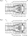
- Figure 4 shows a schematic representation of a further endoscope 10 and a further image detecting device 70.
- the sectional plane shown in Figure 4 corresponds to the sectional planes of the Figures 1 through 3 .
- the endoscope 10 and the image detecting device 70 shown in Figure 4 are similar to the endoscopes and image detecting devices described above with reference to Figures 1 through 3 .
- Below, in particular features, characteristics and functions of the endoscope 10 and the image detecting device 70 shown in Figure 4 which are different from those of the endoscopes and the image detecting devices described above with reference to Figures 1 through 3 are described.
- the image detecting device 70 comprises an image evaluating circuit 89 comparing image data received from the image sensors 82.
- the image evaluating circuit 89 calculates, from the image data, the difference of the positions of the reflecting interfaces 42.
- the image evaluating circuit 89 provides corresponding position information to the data processing circuits 88 or to the image sensors 82 and causes them to exclusively provide image data referring to the regions 83 corresponding to the positions of the reflecting interfaces 42.
- the image evaluating circuit 89 receives image data from the entire image sensors 82 but discards image data not referring to the regions 83 and exclusively forwards image data referring to the regions 83 to a display.
- Figure 5 shows a schematic sectional representation of the endoscope 10 and the image detecting device 70 described above with reference to Figures 1 and 2 .
- the sectional plane of Figure 5 is orthogonal to the sectional planes of Figures 1 and 2 and orthogonal to the longitudinal axis 28 of the shaft 20 (cf. Figures 1 and 2 ).
- the optical axes 38 of the light paths Upstream from the reflecting interfaces 42, the optical axes 38 of the light paths are orthogonal to the sectional plane of Figure 5 , and downstream from the reflecting interfaces 42, the optical axes 38 of the light paths are parallel to the sectional plane of Figure 5.
- Figure 5 shows a configuration different from the configuration shown in Figures 1 and 2 . Both prisms 40 are adjusted to the same longitudinal position, and, downstream from the reflecting interfaces, the optical axes 38 of both light paths are in the sectional plane of Figure 5 .
- sections corresponding to the section shown in Figure 5 are substantially similar to the section shown in Figure 5 .
- the rod lens units 33, 35, 36 (cf. Figures 1, 2 ) are not in the sectional plane of Figure 5 . However, the projections of the most proximal rod lenses 36 are schematically represented by broken lines in Figure 5 .
- the sectional plane of Figure 5 intersects the inclined reflecting interface 42.
- the positions of the optical axes 38 upstream from the reflecting surface 42 are indicated by crosses at the centers of the rod lenses 36, and the optical axes 38 downstream from the reflecting surfaces 42 are represented by broken lines.
- Figure 6 shows a schematic sectional representation of a further endoscope 10 and a further image detecting device 70.
- the sectional plane of Figure 6 corresponds to the sectional plane of Figure 5 .
- the configuration shown in Figure 6 corresponds to the configuration shown in Figure 5 (both prisms 40 adjusted to the same longitudinal positions).
- the endoscope 10 and the image detecting device 70 shown in Figure 6 are similar to the endoscopes and the image detecting devices, respectively, described above with reference to Figures 1 through 5 .
- the endoscope 10 and the image detecting device 70 shown in Figure 6 which are different from those of the endoscope and the image detecting device described above with reference to Figures 1 through 5 are described.
- the directions of propagation of light from an object to the image sensors 82 are parallel not only upstream from but also downstream from the reflecting interfaces 42.
- the window elements 39 of the endoscope 10 are not positioned at opposite sides of the casing 13 of the endoscope 10, but side by side, and the image sensors 82 of the image detecting device 70 are not positioned at opposite sides of the recess 76, but side by side.
- a single image sensor with an active area of adequate dimensions to capture both images relayed by the reflecting interfaces 42 on a single active area can be provided rather than proving two distinct image sensors 82.
- the individual images could then be resolved by a single image processing circuit 88 or by two image processing circuits 88 each of which reading image data from a respective region of the active area comprising the respective image only or by other means.
- Figure 7 shows a schematic sectional representation of a further endoscope 10 and a further image detecting device 70.
- the sectional plane of Figure 7 corresponds to the sectional planes of Figures 5 and 6 .
- the configuration shown in Figure 7 corresponds to the configurations shown in Figures 5 and 6 (all prisms 40 adjusted to the same longitudinal positions).
- the endoscope 10 and the image detecting device 70 shown in Figure 7 are similar to the endoscopes and the image detecting devices, respectively, described above with reference to Figures 1 through 6 .
- the endoscope 10 and the image detecting device 70 shown in Figure 7 which are different from those of the endoscopes and the image detecting devices described above with reference to Figures 1 through 6 are described.
- the endoscope 10 shown in Figure 7 comprises four parallel light paths formed by four parallel arrangements of rod lenses 36.
- Four similar prisms 40 are provided at four sliding carriages 42, each prism comprising a reflecting interface 42 bending the optical axis of the corresponding light path by 90 degrees.
- the image detecting device 70 comprises four similar image sensors 82. Each of the image sensors 82 captures the images relayed by a corresponding rod lens 36 and reflected by a corresponding reflecting interface 42.
- a pair of image sensors 82 are arranged side by side at one printed circuit board 81, and another pair of image sensors 82 are arranged side by side at another printed circuit board 81, wherein both circuit boards are arranged at opposite sides of the recess 76.
- the directions of propagation of light from an object to the image sensors 82 at the same printed circuit board are parallel, and the directions of propagation of light from an object to image sensors 82 at different printed circuit boards are anti-parallel.
- each pair of image sensors 82 located side by side can be replaced by a single image sensor with an active area of adequate dimensions to capture both images relayed by the respective pair of reflecting interfaces 42.
- the individual images could then be resolved by a single image processing circuit 88 or by two image processing circuits 88 each of which reading image data from a region of the active area comprising the respective image only or by other means.
- the reflecting interfaces 42 can be located and oriented such that all the four images relayed by the four reflecting interfaces 42 are, side by side, projected on a single image detector with an active area of adequate dimensions to capture all four images.
- the individual images could then be resolved by a single image processing circuit 88 or by two or more image processing circuits 88 each of which reading image data from a region of the active area comprising one or two respective images only or by other means.
- the image sensors 82 can be arranged at different positions, for example one image sensor 82 at each of four sides of the recess 76.
- the endoscope 10 comprises two window elements 39, and each window element 39 at the endoscope is provided for two parallel light paths.
- four separate windows can be provided, wherein each window element is allocated to one of the light paths of the endoscope 10 (similar to the embodiment described above with reference to Figure 6 ).
- the image detecting device 70 comprises two window elements 74, and each window element 74 at the endoscope is provided for one pair of image sensors 82.
- each window element 74 at the endoscope is provided for one pair of image sensors 82.
- four separate windows can be provided, wherein each window element is allocated to one of the image sensors 82.
- the endoscope 10 can, as an alternative, comprise a single window element 39 for both light paths (similar to the endoscope shown in Figure 7 ) and/or the image detecting device 70 can comprise a single window element 74 for both image sensors 82 (similar to the image detecting device shown in Figure 7 ).
- Figure 8 shows a schematic sectional representation of a further endoscope 10 and a further image detecting device 70.
- the sectional plane of Figure 8 corresponds to the sectional planes of Figures 5 through 7 .
- the configuration shown in Figure 8 corresponds to the configurations shown in Figures 5 through 7 (all prisms 40 adjusted to the same longitudinal positions).
- the endoscope 10 and the image detecting device 70 shown in Figure 8 are similar to the endoscope and the image detecting device, respectively, described above with reference to Figures 1 through 7 .
- the endoscope 10 and the image detecting device 70 shown in Figure 8 which are different from those of the endoscope and the image detecting device described above with reference to Figures 1 through 7 are described.
- the endoscope 10 shown in Figure 8 comprises three parallel light paths, each light path formed by a set of rod lenses 36 and a prism 40 comprising a reflecting interface 42.
- the image detecting device shown in Figure 8 comprises three image sensors 82 and three windows 74 allocated to the image sensors 82.
- the light paths' optical axes 38 downstream from the reflecting interfaces 42 are arranged tangentially, i.e. straight lines comprising the optical axes 38 downstream from the reflecting interfaces 42 do not intersect in one but in three different points.
- the optical axes 38 downstream from the reflecting interfaces 42 can be arranged radially, i.e. straight lines comprising the optical axes 38 downstream from the reflecting interfaces 42 intersect in a single point.
- the proximal end 16 of the endoscope 10 and the recess 76 of the image detecting device 70 can be designed such that the endoscope 10 can be easily rotated with respect to the image detecting device 70.
- both the cross section of the proximal end 16 of the endoscope 10 and the cross section of the recess 76 of the image detecting device can be circular.
- the number of image sensors 82 of each of the image detecting devices 70 shown in Figure 7 and 8 can be less than the number of light paths.
- the number of image sensors 82 may be two.
- the endoscope 10 can be rotated with respect to the image detecting device to different predetermined rotational positions in which the image sensors 82 are optically coupled to different pairs of light paths.
- rotation of the endoscope can rotate the viewing direction on a cone, and stereoscopic imaging in a number of different predetermined directions is facilitated.
- the rails 14 defining the paths of the sliding carriages 44 are dovetail guides.
- other linear guides or linear bearings can be provided.
- the image detecting device laterally encloses the proximal end 16 of the endoscope 10 completely.
- the cross section of the image detecting device can be U-shaped or C-shaped, thereby positively holding or locking the proximal end 16 of the endoscope 10 into a well defined position without completely enclosing it.
- the reflecting interfaces 42 can be part of prisms, mirrors or other optical elements.
- the reflecting interfaces 42 and/or other surfaces of prisms 40 can be curved.
- the image sensors 82 can be integral with the optically transparent window elements 74.
Landscapes
- Health & Medical Sciences (AREA)
- Life Sciences & Earth Sciences (AREA)
- Surgery (AREA)
- Physics & Mathematics (AREA)
- Engineering & Computer Science (AREA)
- Optics & Photonics (AREA)
- General Health & Medical Sciences (AREA)
- Radiology & Medical Imaging (AREA)
- Biophysics (AREA)
- Public Health (AREA)
- Pathology (AREA)
- Heart & Thoracic Surgery (AREA)
- Nuclear Medicine, Radiotherapy & Molecular Imaging (AREA)
- Biomedical Technology (AREA)
- Veterinary Medicine (AREA)
- Medical Informatics (AREA)
- Molecular Biology (AREA)
- Animal Behavior & Ethology (AREA)
- Astronomy & Astrophysics (AREA)
- General Physics & Mathematics (AREA)
- Multimedia (AREA)
- Signal Processing (AREA)
- Endoscopes (AREA)
- Instruments For Viewing The Inside Of Hollow Bodies (AREA)
Abstract
Description
- The present invention refers to an endoscope, a borescope, an exoscope or another image relaying device and to an image detecting device detecting or sensing or capturing an image relayed by an image relaying device. In particular, the image relaying device and the image detecting device are configured to relay or detect, respectively, stereo images comprising at least a first image to be provided to a left eye of a user and a second image to be provided to a right eye of the user, thereby producing a three-dimensional impression.
- An exoscope is an image relaying device configured for being positioned and used outside a human or animal body. Like a surgical microscope, or operating microscope, an exoscope is provided for imaging of objects at or close to the surface of the body and visible from outside. In many cases, an exoscope is smaller than a surgical microscope. In many cases, an exoscope is provided for a larger object distance than a surgical microscope is. Unlike an endoscope, an exoscope may not be adapted for being inserted, through a natural or artificial orifice, into a cavity but configured to operate outside the body.
- A borescope is similar to an endoscope but generally adapted for technical applications rather than for medical applications.
- Conventional stereoscopic endoscopes, borescopes or exoscopes comprise two objective lenses and two image sensors at their distal ends. Other stereo endoscopes or stereo exoscopes comprise two objectives at their distal ends, two image relaying systems relaying images produced by the objective lenses to their proximal end, and two image sensors at their proximal end. Other conventional stereo endoscopes comprise two objective lenses at their distal end, two image relaying systems relaying images produced by the objective lenses to their proximal end, and two parallel interfaces at their proximal end allowing a mechanical and optical coupling of a stereo camera with two image sensors to the proximal end of the stereo endoscope.
- For many applications, there are good reasons not to integrate image sensors into an endoscope or into an exoscopes, in particular regarding costs of manufacture and repair, adaptability to different applications with different hardware requirements, and sterilization. When the image sensing or image detecting device is separable from the image relaying device, the interface between both devices and the compensation of variations within the manufacturing tolerance provides particular challenges.
- An object of the present invention is to provide an improved endoscope or exoscope or other image relaying device and an improved image detecting device, in particular facilitating compensation for variations of characteristics of components and providing a high quality interface between both devices.
- This object is solved by the subject matters of the independent claims.
- Further embodiments are described in the dependent claims.
- Embodiments of the present application are based on the idea to provide an interface between an image relaying device and an image detecting device that is, compared to conventional devices, rotated by a given angle, for example, 90 degrees. Light from an object to be observed or imaged travels parallel to a shaft of the image relaying device, is reflected in a proximal end region of the device, and passes a window travelling in a direction orthogonal to the longitudinal axis of the shaft. A window in a proximal end region of the image relaying device through which window the light leaves the image relaying device and a window of the image detecting device through which window the light enters the image detecting device can be parallel to each other and also parallel to the longitudinal axis of the shaft of the image relaying device.
- An image relaying device comprises a shaft, an objective lens at a distal end of the shaft, an optically transparent window region in a proximal end region of the image relaying device, and an optical system in the shaft, the optical system relaying an image produced by the objective lens to the proximal end region such that the relayed image can be captured through the window region, wherein the optical system's optical axis at the window region is orthogonal or substantially orthogonal to the optical system's optical axis in the shaft.
- The image relaying device is, in particular, an endoscope, a borescope or an exoscope for medical or technical applications. The shaft can be rigid and straight or curved, or flexible. The objective lens at the distal end of the shaft can be configured for a direction of view parallel to the longitudinal axis of a shaft or for any other predetermined constant or variable direction of view.
- The optically transparent window region is, in particular, at least a part of an opening of a casing, or housing of the image relaying device. This opening is, in particular, hermetically closed by an optically transparent window element made of glass, sapphire or any other optically transparent material. The proximal end region of the image relaying device can be a proximal end region of the shaft. As an alternative, the proximal end region of the image relaying device can have a cross section different from, and, in particular, larger than the cross section of the shaft.
- In case of a rigid and straight shaft, the optical system comprises, for example, a series of rod lenses or other relay lens units wherein each relay lens unit produces, from a first real intermediate image distal to the relay lens unit, a second real intermediate image proximal to the relay lens unit. The most proximal real intermediate image can be orthogonal or parallel to the optical system's optical axis in the shaft. The optical system can be configured to produce, from the most proximal real intermediate image, a virtual image which can be captured by a camera. As an alternative, the optical system can be configured to produce a real image outside, or downstream from, the optically transparent window region at a place where the image sensor of an image detecting device can be placed.
- The optical system's optical axis at the window region can be orthogonal or substantially orthogonal or, as an alternative, not parallel to the optical system's optical axis in the shaft.
- In an image relaying device as described herein, the optical system can comprise a reflecting interface bending the optical system's optical axis.
- The reflecting interface can be a surface of a mirror (i.e. an interface between air or another gas or vacuum or glass and a thin metal layer). As an alternative, the reflecting interface can be a surface of a prism or an interface between two prisms made of materials with different refractive indices, wherein total internal reflection occurs at the interface.
- The angles between the reflecting interface and each arm of the optical system's optical axis are, in particular, 45 degrees. The reflecting interface is, in particular, arranged between the proximal end of the most proximal rod lens or other relay unit and the optically transparent window region. In particular, no light refracting element is situated between the reflecting interface and the optically transparent window region.
- An image relaying device as described herein can further comprise an adjustment mechanism facilitating adjustment of the position of the reflecting interface.
- In particular, the adjustment mechanism facilitates adjustment of the position of the reflecting interface at or near the end of manufacture or during maintenance or repair of the image relaying device or at some other time post manufacture. After adjustment of the adjustment mechanism, the adjustment mechanism can be sealed or blocked as a final or near-final step of manufacture or maintenance or repair.
- In particular, the adjustment mechanism supports the reflecting interface (i.e. the mirror or prism comprising the reflecting interface). For example, the adjustment mechanism may comprise a sliding carriage which can be moved in one direction along a rail or another structure. The adjustment mechanism may also comprise a screw wherein a rotation of the screw causes a displacement of the reflecting interface.
- Characteristics of rod lenses or other components of the optical system are dispersed within a non-punctiform region of manufacturing tolerance, or engineering tolerance. As a consequence of dispersion of characteristics, the position of the most proximal real intermediate image never exactly corresponds to the original design. The ability to apply an adjustment to the position of the reflecting interface allows for a compensation of the position of the most proximal image produced by the optical system. In this way, the position of the most proximal (real or virtual) image produced by the optical system of an image relaying device can be adjusted precisely to an optimum design position. With this adjustment or compensation, the image relaying device provides an improved interface to an image detecting device.
- In an image relaying device as described herein, the adjustment mechanism can facilitate translational displacement of the reflecting interface in a direction not parallel to the reflecting interface.
- In an image relaying device as described herein, the adjustment mechanism can facilitate translational displacement of the reflecting interface in a direction parallel to the longitudinal axis of the shaft.
- In an image relaying device as described herein, the adjustment mechanism can facilitate translational displacement of the reflecting interface in a direction parallel to the optical system's optical axis in the shaft or at the window region.
- Translational displacement of the reflecting interface in a direction not parallel to the reflecting interface alters the length of the optical path from the objective lens along the optical system to the window region. A translational displacement of the reflecting interface in a direction parallel to the longitudinal axis of the shaft can be achieved with a sliding carriage moving along any kind of rail parallel to the shaft. A translational displacement of the reflecting interface in any other predetermined direction can be achieved with a sliding carriage moving along any kind of rail parallel to this predetermined direction.
- An image relaying device as described herein can comprise a position indicator providing information comprising the position of the reflecting interface to a receiver outside the image relaying device.
- In an image relaying device as described herein, the position indicator can comprise a magnet at the adjustment mechanism.
- The magnetic field produced by the magnet can be sensed or detected outside the casing of the image relaying device. In particular, a Hall effect sensor, or Hall sensor, or another sensor or detector detecting the flux density and/or direction of the magnetic field produced by the magnet can be used to determine the position of the magnet and, thereby, the position of the adjustment mechanism and the reflecting interface.
- In an image relaying device as described herein, the position indicator can comprise a linear bar code or a two dimensional matrix code wherein the position of the reflecting interface is encoded.
- In an image relaying device as described herein, the optical system can be configured to provide a real image outside a casing of the image relaying device.
- In particular, the optical system is configured to provide a real image in the vicinity of the window region, for example, a few millimeters or several millimeters outside the window region. The real image provided by the optical system can be detected or sensed by an image sensor of an image detecting device comprising no curved refracting or reflecting surface.
- In an image relaying device as described herein, the window region is a first window region and the optical system is a first optical system, wherein the image relaying device further comprises a second optically transparent window region in the proximal end region of the image relaying device and a second optical system in the shaft, wherein the second optical system is similar to the first optical system, wherein the second optical system relays an image produced by the objective lens or by another objective lens to the proximal end region in such a way that the relayed image can be captured through the second window region, wherein the second optical system's optical axis at the second window region is orthogonal or substantially orthogonal to the second optical system's optical axis in the shaft and parallel to the first optical system's optical axis at the first window region.
- An image relaying device as described herein can comprise two window regions and two similar optical systems, wherein the optical systems' optical axes at their respective window regions are parallel to each other.
- Both window regions can be arranged parallel and close to each other. In particular, both window regions can be part of the same optically transparent window element. As an alternative, the window regions can be formed by two different optically transparent window elements. These two different optically transparent window elements can be arranged parallel and/or close to each other or spaced apart from each other. In particular, both window elements can be arranged at opposite sides of the casing of the image relaying device.
- In the shaft, both optical systems are arranged parallel to each other and both optical systems' optical axes are parallel to each other. In particular, both optical systems provide - within the limits of manufacturing tolerance - identical characteristics.
- The image relaying device can comprise more than two optical systems (for example three, four, or five optical systems) and a corresponding number of window regions, wherein all optical systems may provide - within the limits of manufacturing tolerance - identical characteristics.
- In an image relaying device as described herein, the directions of propagation of light in the optical systems at their respective window regions can be opposite to each other.
- In particular, the directions of propagation of light originating from the same observed object in the optical systems at their respective window regions are opposite to each other.
- In an image relaying device as described herein, the two window regions can be formed by two different window elements which are parallel to each other and arranged at opposite sides of a casing of the image relaying device.
- In particular, an image relaying device as described herein is an endoscope or an exoscope or a surgical microscope or a borescope or is part of an endoscope or an exoscope or a surgical microscope or a borescope.
- An image detecting device for an image relaying device comprises an image sensor, a window element, wherein light passing the window element is detected by the image sensor, and a coupling mechanism for a separable mechanical coupling of the image detecting device to an image relaying device, wherein the image detecting device is configured to be coupled to an image relaying device in such a way that a longitudinal axis of a shaft of the image relaying device is parallel to the window element.
- The image detecting device can be configured to be coupled to and functionally combined with an image relaying device as described herein. The image sensor is provided for detecting an image projected onto the image sensor (more particularly onto or into its light sensitive layer) and for generating an (analogue or digital, in particular electric) image signal representing the detected image. As an example, the image sensor can be a CCD- or a CMOS-sensor with a matrix of pixels, or light sensitive elements. The image sensor can comprise a Bayer-filter, i.e. a matrix of red, green and blue filter elements in front of light sensitive elements. As an alternative, the image detecting device can comprise a number of image sensors and a number of dichroic filters, wherein the dichroic filters allow light within a respective predetermined range of wavelengths only to be detected by each image sensor.
- In particular, the window is arranged parallel to the image sensor. The window can face the image sensor or be integral with the image sensor.
- The coupling mechanism can comprise a recess in the casing of the image detecting device, wherein the shape of the recess corresponds to the shape of the proximal end of an image relaying device the image detecting device is provided for. The coupling mechanism can comprise a latching mechanism or a bayonet mechanism or a magnet mechanism allowing to repeatedly couple the image detecting device to an image relaying device and decouple the image detecting device from the image relaying device without damaging either of the devices.
- An image detecting device as described herein can further comprise a receiver for receiving, from a position indicator of an image relaying device, information representing the position of a reflecting interface of the image relaying device.
- The receiver can be configured to receive the information when the image detecting device is coupled to the image relaying device or during the coupling procedure.
- In an image detecting device as described herein, the receiver can comprise a Hall sensor or another sensor sensing the direction or flux density of a magnetic field or a bar code reader or a matrix code reader.
- A Hall sensor or another sensor sensing the direction or the flux density of a magnetic field allows for a determination of the position of a magnet inside the image relaying device. When the position of the reflecting interface inside the image relaying device is unambiguously coupled to the position or orientation of a magnet inside the image relaying device, the position of the reflecting interface can be deduced from the orientation or flux density of a magnetic field produced by the magnet.
- As an alternative, the position of the reflecting interface can be encoded in a bar code or a matrix code at the outer surface of the casing of the image relaying device, and the bar code reader or matrix code reader can read the encoded position.
- An image detecting device as described herein can further comprise a frame positioning circuit determining, from the position information, the position of a region of the image sensor, wherein exclusively image data from within the region are read from the image sensor or exclusively image data from within the region are read from a memory or exclusively image data from within the region are transmitted to a display or exclusively image data from within the region are stored in a memory.
- The frame positioning circuit may be partially or entirely identical to an image evaluating circuit or to an image data processing circuit. When the reflecting interfaces of different image relaying devices are located at different positions, the images relayed by the image relaying devices are projected onto different regions of the image sensor of the image detecting device. This can be compensated by the frame positioning circuit electing the respective region of the image sensor in response to the position information.
- An image detecting device as described herein can be configured to detect a real image provided by the image relaying device.
- The image detecting device can be configured to be coupled to an image relaying device providing a real image outside the image relaying device. In this case, the image detecting device can comprise no curved refracting or reflecting interface. Rather, the image sensor can be positioned just behind the window element of the image detecting device. In particular, the image sensor can be integral with the window element of the image detecting device.
- An image detecting device as described herein can comprise two image sensors, wherein the image detecting device is configured to receive, in a region between the image sensors, a proximal end region of an image relaying device comprising two optical systems simultaneously relaying two images, in a way that each of the images relayed by one of the two optical systems is received by one of the two image sensors.
- When the image detecting device comprises two image sensors and is configured to receive a proximal end region of an image relaying device in a region between the image sensors, the image detecting device comprises, in particular, two window elements.
- The image detecting device can comprise more than two image sensors, for example three, four, or five image sensors. The image detecting device can be configured to be combined with an image relaying device comprising a corresponding number or a different number of optical systems.
- An image detecting device as described herein can further comprise an image evaluating circuit comparing image signals provided by the two image sensors and calculating, from the comparison of the image signals, position information representing the relative positions of reflecting interfaces of the image relaying devices.
- When the reflecting interfaces in the optical systems of the image relaying device are positioned differently, a misalignment, or offset, of the images received by the image sensors results. From a comparison of the image signals, this offset can be calculated and can be used as a position information as described above. In particular, the position of regions of the image sensors (at least the position of a region of one image sensor) can be calculated, wherein exclusively image data from within this region or these regions are read, stored or transmitted.
- An image detecting device as described herein can comprise an image sensor with an active area of adequate dimensions to capture, side by side, two images relayed by two optical systems. These two images are captured in distinct regions of the active area of the image sensor. For example, the individual images can be resolved by a single image processing circuit or by two image processing circuits each of which reading image data from the respective region of the active area comprising the respective image only.
- An image detecting device as described herein can comprise an image sensor with an active area of adequate dimensions to capture, side by side, a plurality of images relayed by a respective plurality of optical systems. The plurality of images are captured in distinct regions of the active area of the image sensor. For example, the individual images can be resolved by a single image processing circuit or by a number of image processing circuits each of which reading image data from a respective region of the active area comprising the respective image only.
- Embodiments will be described below with reference to the enclosed Figures.
- Figure 1
- shows a schematic representation of an image relaying device and an image detecting device;
- Figure 2
- shows a schematic representation of the image relaying device and the image detecting device shown in
Figure 1 in another configuration; - Figure 3
- shows a schematic representation of another image relaying device and another image detecting device;
- Figure 4
- shows a schematic representation of another image relaying device and another image detecting device;
- Figure 5
- shows another schematic representation of the image relaying device and the image detecting device shown in
Figure 1 ; - Figure 6
- shows a schematic representation of another image relaying device and another image detecting device;
- Figure 7
- shows a schematic representation of another image relaying device and another image detecting device;
- Figure 8
- shows a schematic representation of another image relaying device and another image detecting device.
-
Figure 1 shows a schematic representation of anendoscope 10 and animage detecting device 70. More particularly,Figure 1 shows a longitudinal section through theendoscope 10 and theimage detecting device 70. Cross sections of non-transparent objects are shown as hatched areas, cross sections of optically transparent elements (window elements, lenses, prisms) are not hatched. - The
endoscope 10 is one example of an image relaying device. Theendoscope 10 comprises a shaft 20. The distal end 21 of the shaft 20 forms the distal end 11 of theendoscope 10. The shape of the shaft 20 is essentially cylindrical with a circular, an elliptical or another cross sectional area. The axis of rotational symmetry of the outer surface of the shaft 20 or, in case of rotational non-symmetry, the line formed by the centers of the cross sectional areas, is called thelongitudinal axis 28 of the shaft 20. - A
proximal end region 16 of the endoscope can provide essentially the same cross section as the shaft 20 or a different cross section. In the configuration shown inFig. 1 , theproximal end region 16 of theendoscope 10 is positioned within arecess 76 of corresponding shape in theimage detecting device 70. - The
casing 13 of theendoscope 10 comprises (at least) four openings all of which are hermetically closed. An opening at the distal end 21 of the shaft 20 is hermetically closed by an opticallytransparent window element 22. Two openings at opposite sides of theproximal end region 16 of theendoscope 10 are hermetically closed by opticallytransparent window elements 39. The opticallytransparent window elements 39 are arranged symmetrically with respect to thelongitudinal axis 28 of the shaft 20. An opening at the proximal end face of theproximal end region 16 of theendoscope 10 is closed by alid 18. - Within the
casing 13 of theendoscope 10, twoobjective lenses 30 immediately proximal to thewindow element 22 at the distal end 21 of the shaft 20, a number ofrod lenses prisms 40 are arranged. Two tubes 31 are arranged in parallel inside the shaft 20. One of two end guides 32 is fixed to the proximal end of each tube 31. Each tube 31 holds a number ofrod lenses objective lenses 30, therod lenses prisms 40 form a light path. Both light paths are essentially similar, and are arranged symmetrical with respect to a plane of symmetry, wherein the plane of symmetry is orthogonal to the sectional plane shown inFigure 1 and comprises thelongitudinal axis 28 of the shaft 20. Therefore, reference numerals refer to only one of the two light paths. - In each light path, the respective
objective lens 30 produces a real image of an object observed by means of theendoscope 10. This real image produced by theobjective lens 30 is relayed to theproximal end region 16 of theendoscope 10 by means of therod lenses objective lens 30 and therod lens units optical axis 38 of the light path. Theprism 40 comprises a reflectinginterface 42 at an angle of 45 degrees with respect to theoptical axis 38 of the light path upstream from (distal to) the reflectinginterface 42 and at an angle of 45 degrees with respect to theoptical axis 38 of the light path downstream from the reflectinginterface 42. The reflectinginterface 42 reflects the light transmitted by the objective 30 and therod lens units optical axis 38 by 90 degrees. Upstream from the reflectinginterface 42 theoptical axis 38 of the light path is parallel to thelongitudinal axis 28 of the shaft 20. Downstream from the reflectinginterface 42 theoptical axis 38 of the light path is orthogonal to thelongitudinal axis 28 of the shaft 20. Downstream from the reflectinginterface 42 the light path leaves theendoscope 10 through therespective window element 39 and theoptical axis 38 of the light path crosses therespective window element 39. - Each of the
prisms 40 is held, carried or supported by a respective slidingcarriage 44. Each slidingcarriage 44 is slidably fixed to arail 14 integral with or rigidly connected to thecasing 13 of theendoscope 10. Therails 14 define a predetermined path parallel to thelongitudinal axis 28 of the shaft 20 and inhibit any motion of therespective carriage 44 in any direction perpendicular to therail 14. - At each sliding
carriage 44, an adjustingscrew 45 and a spring 46 (not shown in sectional view) are provided. One end of the adjustingscrew 45 and one end of thespring 46 rest on asupport 15 integral with or rigidly connected to thecasing 13. The other end of thespring 46 rests at a surface of the slidingcarriage 44 opposite to thesupport 15. The thread of the adjustingscrew 45 engages in a corresponding thread in the slidingcarriage 44. Therefore, any rotation of the adjustingscrew 45 causes a translational displacement of the slidingcarriage 44. - At each sliding
carriage 44, amagnet 55 is provided producing a magnetic field that can be sensed or detected outside thecasing 13 of theendoscope 10. - A
notch 19 is provided in the outer surface of thecasing 13 of theendoscope 10. A bore 77 is provided in a region of the outer surface of thecasing 73 of theimage detecting device 70 which region faces therecess 73. In thebore 77, ahelical spring 78 and aball 79 are provided. In the configuration shown inFigure 1 , thehelical spring 78 presses theball 79 into thenotch 19 in the outer surface of thecasing 13 of theendoscope 10. Thenotch 19, thehelical spring 78 and theball 79 form a latching mechanism releasably fixing theproximal end region 16 of theendoscope 10 inside therecess 76 in theimage detecting device 70. - Small clearance between the outer surface of the
proximal end region 16 of theendoscope 10 and the inner surface of therecess 76 of theimage detecting device 70 and thelatching mechanism Figure 1 , two latchingmechanisms latching mechanism - The
casing 73 of theimage detecting device 70 comprises, at opposites sides of therecess 76, two opticallytransparent window elements 74 hermetically or fluid tightly closing openings in thecasing 73. In the configuration shown inFigure 1 , eachwindow element 74 of theimage detecting device 70 is positioned parallel and opposite to arespective window 39 of theendoscope 10. Behind eachwindow element 74 of theimage detecting device 70, i.e. inside thecasing 73 of theimage detecting device 70, a printedcircuit board 81 with animage sensor 82, aHall sensor 85 and adata processing unit 88 are provided. Eachimage sensor 82 is parallel to therespective window 74 and, in the configuration shown inFigure 1 , orthogonal to theoptical axis 38 of one of the light paths of theendoscope 10. Eachdata processing circuit 88 is coupled to therespective image sensor 82 and to therespective Hall sensor 85. - Characteristics of optical elements like the
objective lenses 30 and therod lens units image sensor 82 are distributed. Without any compensation by means of the slidingcarriages 44, the most proximal real images - in the example shown inFigure 1 : produced by the most proximal rod lenses 36 - would rarely be precisely within the planes of theimage sensors 82 but almost always slightly upstream or slightly downstream from the planes of theimage sensors 82. Thus, the image sensors would be located out of the respective focal planes for one or both of the light paths and would capture blurred images in most cases. - In the
endoscope 10 shown inFigure 1 , the distribution of the characteristics of theoptical elements interfaces 42 by means of a rotation of the adjusting screws 45 and by the resulting displacements of the slidingcarriages 44. When the positions of thereflective interfaces 42 are adjusted at the end of a manufacturing process of theendoscope 10, the proximal opening of thecasing 13 can be closed by thelid 18. Thelid 18 can be welded to thecasing 13 for a hermetical closure. - As a result of the adjustment of the positions of the reflecting
interfaces 42, the most proximate real images produced by theendoscope 10 are produced precisely in the planes of theimage sensors 82. However, as can be seen from the positions of theoptical axes 38 of the optical paths downstream from the reflectinginterfaces 42, the adjustment of the positions of the reflectinginterfaces 42 results in a lateral displacement of the images projected onto theimage sensors 82. - This lateral displacement of the images projected by the
endoscope 10 onto theimage sensors 82 is compensated by thedata processing circuits 88. Eachdata processing circuit 88 reads the sensor signal of therespective Hall sensor 85. From the sensor signals of theHall sensors 85, thedata processing circuits 88 can calculate the positions of themagnets 55 at the slidingcarriages 44. From the calculated positions of the slidingcarriages 44 thedata processing circuits 88 can calculate the positions of theregions 83 of theimage sensors 82 onto which the endoscope projects the images. Eachdata processing circuit 88 instructs therespective image sensor 82 to provide image data referring to the respective region only. As an alternative, all the image data of theimage sensors 82 are read by thedata processing circuits 88 but thedata processing circuits 88 discard image data not referring to the selectedregions 83 and merely provide image data referring to the selectedregions 83 to a display. -
Figure 2 shows a further schematic representation of theendoscope 10 and theimage detecting device 70 described above with reference toFigure 1 . The sectional plane shown inFigure 2 corresponds to the sectional plane ofFigure 1 . - The configuration shown in
Figure 2 is different from the configuration shown inFigure 1 . In the configuration shown inFigure 2 , theproximal end region 16 of theendoscope 10 is only partially inserted into therecess 76 of theimage detecting device 70. The configuration shown inFigure 1 is an intermediate state temporarily existing when the image relaying device and the image detecting device are combined (to form the system and configuration shown inFigure 1 ) or separated. -
Figure 3 shows a schematic representation of afurther endoscope 10 and a furtherimage detecting device 70. The sectional plane ofFigure 3 corresponds to the sectional planes ofFigures 1 and 2 . With respect to many features, characteristics and functions, theendoscope 10 and theimage detecting device 70 shown inFigure 3 are similar to the endoscope and the image detecting device described above with reference toFigures 1 and 2 . Below, in particular features, characteristics and functions of theendoscope 10 and theimage detecting device 70 shown inFigure 3 which are different from those of the endoscope and the image detecting device described above with reference toFigures 1 and 2 are described. - In contrast to the endoscope described above with reference to
Figures 1 and 2 , theendoscope 10 shown inFigure 3 comprises amirror 41 instead of a prism. Themirror 41 comprises a reflecting layer, for instance an aluminum or silver layer. The surface of this reflecting layer is a reflecting interface. - In contrast to the endoscope described above with reference to
Figures 1 and 2 , no magnets are provided at the slidingcarriages 44 of theendoscope 10 shown inFigure 3 . Instead, a bar code or - as shown inFigure 3 - twobar codes 56 are provided at the outer surface of thecasing 13 in theproximal end region 16 of theendoscope 10. Thesebar codes 56 numerically encode the positions of the reflectinginterfaces 42 set by means of the adjusting screws 45 at the end of the manufacturing process. - In contrast to the image detecting device described above with reference to
Figures 1 and 2 , theimage detecting device 70 shown inFigure 3 comprises a bar code reader or - as shown inFigure 3 - twobar code readers 86. Thebar codes 56 and thebar code readers 86 are arranged such that thebar code readers 86 can read thebar codes 56 when theproximal end region 16 of theendoscope 10 is inserted into therecess 86 of theimage detecting device 70. Thedata processing circuits 88 receive the position information encoded in thebar codes 56 and read by thebar code readers 86 and, depending on the position information, select theregions 83 of theimage sensors 82. -
Figure 4 shows a schematic representation of afurther endoscope 10 and a furtherimage detecting device 70. The sectional plane shown inFigure 4 corresponds to the sectional planes of theFigures 1 through 3 . With respect to many features, characteristics and functions, theendoscope 10 and theimage detecting device 70 shown inFigure 4 are similar to the endoscopes and image detecting devices described above with reference toFigures 1 through 3 . Below, in particular features, characteristics and functions of theendoscope 10 and theimage detecting device 70 shown inFigure 4 which are different from those of the endoscopes and the image detecting devices described above with reference toFigures 1 through 3 are described. - Similar to the endoscope described above with reference to
Figure 3 , no magnets are provided at the sliding carriages of theendoscope 10 shown inFigure 4 . Furthermore, no bar code or other indicator provides information regarding the positions of the reflecting interfaces 42. Rather, theimage detecting device 70 comprises animage evaluating circuit 89 comparing image data received from theimage sensors 82. Theimage evaluating circuit 89 calculates, from the image data, the difference of the positions of the reflecting interfaces 42. Theimage evaluating circuit 89 provides corresponding position information to thedata processing circuits 88 or to theimage sensors 82 and causes them to exclusively provide image data referring to theregions 83 corresponding to the positions of the reflecting interfaces 42. As an alternative, theimage evaluating circuit 89 receives image data from theentire image sensors 82 but discards image data not referring to theregions 83 and exclusively forwards image data referring to theregions 83 to a display. - The functionalities and capabilities and tasks of the
data processing circuits 88 and theimage evaluating circuit 89 can be distributed differently from the schematic representations inFigures 1 through 4 . -
Figure 5 shows a schematic sectional representation of theendoscope 10 and theimage detecting device 70 described above with reference toFigures 1 and 2 . The sectional plane ofFigure 5 is orthogonal to the sectional planes ofFigures 1 and 2 and orthogonal to thelongitudinal axis 28 of the shaft 20 (cf.Figures 1 and 2 ). Upstream from the reflectinginterfaces 42, theoptical axes 38 of the light paths are orthogonal to the sectional plane ofFigure 5 , and downstream from the reflectinginterfaces 42, theoptical axes 38 of the light paths are parallel to the sectional plane ofFigure 5. Figure 5 shows a configuration different from the configuration shown inFigures 1 and 2 . Bothprisms 40 are adjusted to the same longitudinal position, and, downstream from the reflecting interfaces, theoptical axes 38 of both light paths are in the sectional plane ofFigure 5 . - In the embodiments described above with reference to
Figures 3 and 4 , sections corresponding to the section shown inFigure 5 are substantially similar to the section shown inFigure 5 . - The
rod lens units Figures 1, 2 ) are not in the sectional plane ofFigure 5 . However, the projections of the mostproximal rod lenses 36 are schematically represented by broken lines inFigure 5 . - The sectional plane of
Figure 5 intersects the inclined reflectinginterface 42. The positions of theoptical axes 38 upstream from the reflectingsurface 42 are indicated by crosses at the centers of therod lenses 36, and theoptical axes 38 downstream from the reflectingsurfaces 42 are represented by broken lines. -
Figure 6 shows a schematic sectional representation of afurther endoscope 10 and a furtherimage detecting device 70. The sectional plane ofFigure 6 corresponds to the sectional plane ofFigure 5 . The configuration shown inFigure 6 corresponds to the configuration shown inFigure 5 (bothprisms 40 adjusted to the same longitudinal positions). - With respect to many features, characteristics and functions, the
endoscope 10 and theimage detecting device 70 shown inFigure 6 are similar to the endoscopes and the image detecting devices, respectively, described above with reference toFigures 1 through 5 . Below, in particular features, characteristics and functions of theendoscope 10 and theimage detecting device 70 shown inFigure 6 which are different from those of the endoscope and the image detecting device described above with reference toFigures 1 through 5 are described. - In contrast to the endoscopes described above with reference to
Figures 1 through 5 , in theendoscope 10 shown inFigure 6 , the directions of propagation of light from an object to theimage sensors 82 are parallel not only upstream from but also downstream from the reflecting interfaces 42. Hence, thewindow elements 39 of theendoscope 10 are not positioned at opposite sides of thecasing 13 of theendoscope 10, but side by side, and theimage sensors 82 of theimage detecting device 70 are not positioned at opposite sides of therecess 76, but side by side. - One consequence of the configuration shown in
Figure 6 is that the images captured by theimage sensors 82 can be compared more easily. Different positions of the reflecting interfaces 42 (cf.Figures 1 through 4 ) cause an offset of both images in a direction orthogonal to the stereo basis. This offset does not interfere with the disparity caused by the distance of the object. - Another consequence of the configuration shown in
Figure 6 is that bothimage sensors 82 can be provided on the same printedcircuit board 81. - As an alternative, a single image sensor with an active area of adequate dimensions to capture both images relayed by the reflecting interfaces 42 on a single active area can be provided rather than proving two
distinct image sensors 82. The individual images could then be resolved by a singleimage processing circuit 88 or by twoimage processing circuits 88 each of which reading image data from a respective region of the active area comprising the respective image only or by other means. -
Figure 7 shows a schematic sectional representation of afurther endoscope 10 and a furtherimage detecting device 70. The sectional plane ofFigure 7 corresponds to the sectional planes ofFigures 5 and 6 . The configuration shown inFigure 7 corresponds to the configurations shown inFigures 5 and 6 (allprisms 40 adjusted to the same longitudinal positions). - With respect to many features, characteristics and functions, the
endoscope 10 and theimage detecting device 70 shown inFigure 7 are similar to the endoscopes and the image detecting devices, respectively, described above with reference toFigures 1 through 6 . Below, in particular features, characteristics and functions of theendoscope 10 and theimage detecting device 70 shown inFigure 7 which are different from those of the endoscopes and the image detecting devices described above with reference toFigures 1 through 6 are described. - In contrast to the endoscopes described above with reference to
Figures 1 through 6 , theendoscope 10 shown inFigure 7 comprises four parallel light paths formed by four parallel arrangements ofrod lenses 36. Foursimilar prisms 40 are provided at four slidingcarriages 42, each prism comprising a reflectinginterface 42 bending the optical axis of the corresponding light path by 90 degrees. - The
image detecting device 70 comprises foursimilar image sensors 82. Each of theimage sensors 82 captures the images relayed by a correspondingrod lens 36 and reflected by a corresponding reflectinginterface 42. - In the example shown in
Figure 7 , a pair ofimage sensors 82 are arranged side by side at one printedcircuit board 81, and another pair ofimage sensors 82 are arranged side by side at another printedcircuit board 81, wherein both circuit boards are arranged at opposite sides of therecess 76. Correspondingly, the directions of propagation of light from an object to theimage sensors 82 at the same printed circuit board are parallel, and the directions of propagation of light from an object to imagesensors 82 at different printed circuit boards are anti-parallel. - As an alternative similar to the alternative described above with reference to
Figure 6 , each pair ofimage sensors 82 located side by side can be replaced by a single image sensor with an active area of adequate dimensions to capture both images relayed by the respective pair of reflecting interfaces 42. Again, the individual images could then be resolved by a singleimage processing circuit 88 or by twoimage processing circuits 88 each of which reading image data from a region of the active area comprising the respective image only or by other means. - As a further alternative, the reflecting
interfaces 42 can be located and oriented such that all the four images relayed by the four reflectinginterfaces 42 are, side by side, projected on a single image detector with an active area of adequate dimensions to capture all four images. Again, the individual images could then be resolved by a singleimage processing circuit 88 or by two or moreimage processing circuits 88 each of which reading image data from a region of the active area comprising one or two respective images only or by other means. - As a further alternative, the
image sensors 82 can be arranged at different positions, for example oneimage sensor 82 at each of four sides of therecess 76. - In the example shown in
Figure 7 , theendoscope 10 comprises twowindow elements 39, and eachwindow element 39 at the endoscope is provided for two parallel light paths. As an alternative, four separate windows can be provided, wherein each window element is allocated to one of the light paths of the endoscope 10 (similar to the embodiment described above with reference toFigure 6 ). - In the example shown in
Figure 7 , theimage detecting device 70 comprises twowindow elements 74, and eachwindow element 74 at the endoscope is provided for one pair ofimage sensors 82. As an alternative, four separate windows can be provided, wherein each window element is allocated to one of theimage sensors 82. - In the example shown in
Figure 6 , theendoscope 10 can, as an alternative, comprise asingle window element 39 for both light paths (similar to the endoscope shown inFigure 7 ) and/or theimage detecting device 70 can comprise asingle window element 74 for both image sensors 82 (similar to the image detecting device shown inFigure 7 ). -
Figure 8 shows a schematic sectional representation of afurther endoscope 10 and a furtherimage detecting device 70. The sectional plane ofFigure 8 corresponds to the sectional planes ofFigures 5 through 7 . The configuration shown inFigure 8 corresponds to the configurations shown inFigures 5 through 7 (allprisms 40 adjusted to the same longitudinal positions). - With respect to many features, characteristics and functions, the
endoscope 10 and theimage detecting device 70 shown inFigure 8 are similar to the endoscope and the image detecting device, respectively, described above with reference toFigures 1 through 7 . Below, in particular features, characteristics and functions of theendoscope 10 and theimage detecting device 70 shown inFigure 8 which are different from those of the endoscope and the image detecting device described above with reference toFigures 1 through 7 are described. - The
endoscope 10 shown inFigure 8 comprises three parallel light paths, each light path formed by a set ofrod lenses 36 and aprism 40 comprising a reflectinginterface 42. Correspondingly, the image detecting device shown inFigure 8 comprises threeimage sensors 82 and threewindows 74 allocated to theimage sensors 82. - In the example shown in
Figure 8 , the light paths'optical axes 38 downstream from the reflectinginterfaces 42 are arranged tangentially, i.e. straight lines comprising theoptical axes 38 downstream from the reflectinginterfaces 42 do not intersect in one but in three different points. As an alternative, theoptical axes 38 downstream from the reflectinginterfaces 42 can be arranged radially, i.e. straight lines comprising theoptical axes 38 downstream from the reflectinginterfaces 42 intersect in a single point. - In particular in the latter case, the
proximal end 16 of theendoscope 10 and therecess 76 of theimage detecting device 70 can be designed such that theendoscope 10 can be easily rotated with respect to theimage detecting device 70. For example, both the cross section of theproximal end 16 of theendoscope 10 and the cross section of therecess 76 of the image detecting device can be circular. - The same applies to the
endoscope 10 and the image detecting device described above with reference toFigure 7 , in particular, when theoptical axes 38 downstream from the reflectinginterfaces 42 are arranged radially. - The number of
image sensors 82 of each of theimage detecting devices 70 shown inFigure 7 and8 can be less than the number of light paths. In particular, the number ofimage sensors 82 may be two. Theendoscope 10 can be rotated with respect to the image detecting device to different predetermined rotational positions in which theimage sensors 82 are optically coupled to different pairs of light paths. When the endoscope's viewing direction is not parallel to the longitudinal axis of the shaft, rotation of the endoscope can rotate the viewing direction on a cone, and stereoscopic imaging in a number of different predetermined directions is facilitated. - In the examples shown in
Figures 5 through 8 , therails 14 defining the paths of the slidingcarriages 44 are dovetail guides. As an alternative, other linear guides or linear bearings can be provided. - In each of the examples shown in
Figures 5 through 8 , the image detecting device laterally encloses theproximal end 16 of theendoscope 10 completely. As an alternative, the cross section of the image detecting device can be U-shaped or C-shaped, thereby positively holding or locking theproximal end 16 of theendoscope 10 into a well defined position without completely enclosing it. - In all the endoscopes described above with reference to
Figures 1 through 8 , the reflectinginterfaces 42 can be part of prisms, mirrors or other optical elements. The reflecting interfaces 42 and/or other surfaces ofprisms 40 can be curved. Theimage sensors 82 can be integral with the opticallytransparent window elements 74. -
- 10
- endoscope (as one example of an image relaying device)
- 11
- distal end of the
endoscope 10 - 13
- casing of the
endoscope 10 - 14
- rail for the sliding
carriage 44, integral with or rigidly connected to thecasing 13 - 15
- support for the adjusting
screw 45 and thespring 46 at the slidingcarriage 44 - 16
- proximal end region of the
endoscope 10 - 18
- lid closing an opening of the
casing 14 in theproximal end region 16 of theendoscope 10 - 19
- notch in outer surface of
casing 13, corresponding to ball 69 atimage detecting device 70 - 20
- shaft of the
endoscope 10 - 21
- distal end of the shaft 20
- 22
- optically transparent window element at the distal end 21 of the shaft 21
- 28
- longitudinal axis of the shaft 20
- 30
- objective lens at the distal end 21 of the shaft 20
- 31
- tube holding
rod lens units - 32
- end guide at proximal end of tube 31
- 33
- rod lens unit
- 35
- rod lens unit
- 36
- rod lens unit
- 38
- optical axis of the light path defined by the
objective lens 30, therod lens units surface 42 - 39
- optically transparent window element at the
proximal end region 16 of theendoscope 10 - 40
- prism
- 41
- mirror
- 42
- reflecting interface in the
prism 40 or reflecting surface of themirror 41 - 44
- sliding carriage supporting the
prism 40 or themirror 41 - 45
- adjusting screw positioning the sliding
carriage 44 - 46
- spring between
support 15 and slidingcarriage 44 pressing adjustingscrew 45 towardssupport 15 - 55
- magnet at the sliding
carriage 44 - 56
- bar code at the
proximal end region 16 ofendoscope 10 - 70
- image detecting device
- 73
- casing of the
image detecting device 70 - 74
- optically transparent window element at the
casing 73 facing theimage sensor 82 - 76
- recess in the
casing 73, corresponding toproximal end region 16 ofendoscope 10 - 77
- bore in casing's 73 outer surface region, open to recess 76
- 78
- spring in
bore 77 - 79
- ball in
bore 77 - 81
- printed circuit board of the
image detecting device 70 - 82
- image sensor of the
image detecting device 70 - 83
- selected region of the
image sensor 82 read or forwarded by thedata processing circuit 88 - 85
- Hall sensor of the
image detecting device 70 - 86
- bar code reader of the
image detecting device 70 - 88
- data processing circuit of the
image detecting device 70 - 89
- image evaluating circuit of the
image detecting device 70
Claims (15)
- An image relaying device (10), comprising:a shaft (20);an objective lens (30) at a distal end (21) of the shaft (20);an optically transparent window region (39) in a proximal end region (16) of the image relaying device (10);an optical system (33, 35, 36, 42) in the shaft (20), the optical system (33, 35, 36, 42) relaying an image produced by the objective lens (30) to the proximal end region (16) in a way that the relayed image can be captured through the window region (39);a reflecting interface (42) bending the optical system's (33, 35, 36, 42) optical axis (38),wherein the optical system's (33, 35, 36, 42) optical axis (38) at the window region (39) is orthogonal or substantially orthogonal to the optical system's (33, 35, 36, 42) optical axis (38) in the shaft (20).
- The image relaying device (10) of the preceding claim, further comprising:
an adjustment mechanism (44, 45, 46) facilitating adjustment of the position of the reflecting interface (42). - The image relaying device (10) of the preceding claim, wherein the adjustment mechanism (44, 45, 46) facilitates translational displacement of the reflecting interface (42) in a direction parallel to the longitudinal axis (28) of the shaft (20).
- The image relaying device (10) of one of the preceding claims, further comprising:
a position indicator (55, 56) providing information comprising the position of the reflecting interface (42) to a receiver (85, 86) outside the image relaying device (10). - The image relaying device (10) of the preceding claim, wherein the position indicator comprises a magnet (55) at the adjustment mechanism (44, 45, 46).
- The image relaying device (10) of one of the preceding claims wherein the optical system (33, 35, 36, 42) is configured to provide a real image outside a casing (13) of the image relaying device (10).
- The image relaying device (10) of one of the preceding claims, wherein
the image relaying device (10) comprises at least two window regions (39) and at least two similar optical systems (32, 33, 35, 36, 42),
wherein the optical systems' (32, 33, 35, 36) optical axes (38) at their respective window regions (39) are, optionally, parallel to each other. - The image relaying device (10) of one of the preceding claims, wherein the image relaying device (10) is at least a part of at least one of an endoscope, an exoscope, a surgical microscope, and a borescope.
- An image detecting device (70) for an image relaying device (10), the image detecting device (70) comprising:an image sensor (82);a window element (74), wherein light passing the window element (74) is detected by the image sensor (82);a coupling mechanism (76, 77, 78, 79) for a separable mechanical coupling of the image detecting device (70) to an image relaying device (10),wherein the image detecting device (70) is configured to be coupled to an image relaying device (10) in such a way that a longitudinal axis (28) of a shaft (20) of the image relaying device (10) is parallel to the window element (74).
- The image detecting device (70) of the preceding claim, further comprising:
a receiver (85, 86) for receiving, from a position indicator (55, 56) of an image relaying device (10), information representing the position of a reflecting interface (42) of the image relaying device (10). - The image detecting device (70) of the preceding claim, wherein the receiver comprises a Hall sensor (85) or another sensor sensing the direction or flux density of a magnetic field or a bar code reader (86) or a matrix code reader.
- The image detecting device (70) of one of claims 10 and 11, further comprising:
a frame positioning circuit (88) determining, from the position information, the position of a region (83) of the image sensor (82), wherein exclusively image data from within the region (83) are read from the image sensor (82) or exclusively image data from within the region (83) are read from a memory or exclusively image data from within the region (83) are transmitted to a display or exclusively image data from within the region (83) are stored in a memory. - The image detecting device (70) of one of claims 9 through 12, wherein the image detecting device (70) is configured to detect a real image provided by the image relaying device (10).
- The image detecting device (70) of one of claims 9 through 13, wherein the image detecting device (70)
comprises at least two image sensors (82),
is configured to receive, in a region (76) between the image sensors (82), a proximal end region (16) of an image relaying device (10) comprising at least two optical systems (32, 33, 35, 36, 42) simultaneously relaying two images, in a way that each of the images relayed by one of the at least two optical systems (32, 33, 35, 36, 42) is received by one of the at least two image sensors (82). - The image detecting device (70) of the preceding claim, further comprising:
an image evaluating circuit (89) comparing image signals provided by the at least two image sensors (82) and calculating, from the comparison of the image signals, position information representing the relative positions of reflecting interfaces (42) of the image relaying device (10).
Applications Claiming Priority (1)
| Application Number | Priority Date | Filing Date | Title |
|---|---|---|---|
| DE102017105354.9A DE102017105354A1 (en) | 2017-03-14 | 2017-03-14 | Image transmission device and image detection device |
Publications (3)
| Publication Number | Publication Date |
|---|---|
| EP3376273A2 true EP3376273A2 (en) | 2018-09-19 |
| EP3376273A3 EP3376273A3 (en) | 2018-10-31 |
| EP3376273B1 EP3376273B1 (en) | 2020-08-26 |
Family
ID=61655637
Family Applications (1)
| Application Number | Title | Priority Date | Filing Date |
|---|---|---|---|
| EP18161704.4A Active EP3376273B1 (en) | 2017-03-14 | 2018-03-14 | Image relaying device and image detecting device |
Country Status (3)
| Country | Link |
|---|---|
| US (1) | US11102454B2 (en) |
| EP (1) | EP3376273B1 (en) |
| DE (1) | DE102017105354A1 (en) |
Cited By (1)
| Publication number | Priority date | Publication date | Assignee | Title |
|---|---|---|---|---|
| US20230418024A1 (en) * | 2022-06-23 | 2023-12-28 | Karl Storz Se & Co. Kg | Adjustment Device for Adjusting Optical Components of an Optical Instrument and Device Arrangement |
Families Citing this family (4)
| Publication number | Priority date | Publication date | Assignee | Title |
|---|---|---|---|---|
| WO2019008769A1 (en) * | 2017-07-07 | 2019-01-10 | オリンパス株式会社 | Endoscope device |
| DE102019130593B3 (en) * | 2019-11-13 | 2021-05-20 | Karl Storz Se & Co. Kg | Stereo endoscopes |
| WO2021131921A1 (en) * | 2019-12-27 | 2021-07-01 | 国立大学法人浜松医科大学 | Rigid mirror device |
| DE102020135029A1 (en) | 2020-12-29 | 2022-06-30 | Olympus Winter & Ibe Gmbh | Support for an image sensor of a surgical instrument |
Family Cites Families (15)
| Publication number | Priority date | Publication date | Assignee | Title |
|---|---|---|---|---|
| US5557454A (en) | 1992-12-25 | 1996-09-17 | Olympus Optical Co., Ltd. | Stereoscopic endoscope |
| US5588948A (en) | 1993-02-17 | 1996-12-31 | Olympus Optical Co. Ltd. | Stereoscopic endoscope |
| US6025873A (en) | 1994-04-07 | 2000-02-15 | Olympus Optical Co., Ltd. | Endoscope system provided with low-pass filter for moire removal |
| CN1171467C (en) * | 1999-06-11 | 2004-10-13 | 埃米尔·亨德里克斯 | Three-dimensional scene acquisition with single hand-held camera |
| JP2001083400A (en) * | 1999-09-08 | 2001-03-30 | Olympus Optical Co Ltd | Image pickup optical system |
| US20050197533A1 (en) * | 2000-03-16 | 2005-09-08 | Medivision, Inc. | Endoscope and camera mount |
| US7101334B2 (en) * | 2001-10-31 | 2006-09-05 | Olympus Corporation | Optical observation device and 3-D image input optical system therefor |
| DE102006017003A1 (en) | 2006-04-11 | 2007-10-18 | Friedrich-Alexander-Universität Erlangen-Nürnberg | Endoscope for depth data acquisition in e.g. medical area, has modulation unit controlling light source based on modulation data so that source transmits modulated light signal and evaluation unit evaluating signal to estimate depth data |
| DE102008024789A1 (en) | 2008-05-21 | 2009-12-03 | Richard Wolf Gmbh | Stereo endoscope |
| ES2688280T3 (en) | 2010-03-12 | 2018-10-31 | Viking Systems, Inc. | Stereoscopic display system |
| DE102011119608B4 (en) | 2011-11-29 | 2021-07-29 | Karl Storz Se & Co. Kg | Device and method for endoscopic 3D data acquisition |
| JP5973297B2 (en) | 2012-09-12 | 2016-08-23 | 本田技研工業株式会社 | Borescope |
| DE102014115738B4 (en) | 2014-10-29 | 2021-07-29 | Karl Storz Se & Co. Kg | Endoscope and endoscopic system |
| DE102015118199A1 (en) | 2015-10-26 | 2017-04-27 | Karl Storz Gmbh & Co. Kg | Optical medical instrument |
| US10708574B2 (en) * | 2017-06-15 | 2020-07-07 | Align Technology, Inc. | Three dimensional imaging apparatus with color sensor |
-
2017
- 2017-03-14 DE DE102017105354.9A patent/DE102017105354A1/en not_active Withdrawn
-
2018
- 2018-03-12 US US15/918,709 patent/US11102454B2/en active Active
- 2018-03-14 EP EP18161704.4A patent/EP3376273B1/en active Active
Cited By (2)
| Publication number | Priority date | Publication date | Assignee | Title |
|---|---|---|---|---|
| US20230418024A1 (en) * | 2022-06-23 | 2023-12-28 | Karl Storz Se & Co. Kg | Adjustment Device for Adjusting Optical Components of an Optical Instrument and Device Arrangement |
| US12566311B2 (en) * | 2022-06-23 | 2026-03-03 | Karl Storz Se & Co. Kg | Adjustment device for adjusting optical components of an optical instrument and device arrangement |
Also Published As
| Publication number | Publication date |
|---|---|
| EP3376273B1 (en) | 2020-08-26 |
| DE102017105354A1 (en) | 2018-09-20 |
| US20180270453A1 (en) | 2018-09-20 |
| US11102454B2 (en) | 2021-08-24 |
| EP3376273A3 (en) | 2018-10-31 |
Similar Documents
| Publication | Publication Date | Title |
|---|---|---|
| US11102454B2 (en) | Image relaying device and image detecting device | |
| KR101874547B1 (en) | 3-dimensional intraoral scaner | |
| JP5426174B2 (en) | Monocular 3D imaging | |
| CA2102236C (en) | Stereo video endoscope objective lens system | |
| CN100368764C (en) | measuring machine | |
| US20080117290A1 (en) | Apparatus, system and method for generating stereoscopic images and correcting for vertical parallax | |
| US20030083551A1 (en) | Optical observation device and 3-D image input optical system therefor | |
| US9277206B1 (en) | Dual-view laser-based three-dimensional capture system and method for employing the same | |
| EP3254606A1 (en) | Endoscope and imaging arrangement providing depth of field | |
| KR100972572B1 (en) | Binocular stereoscopic camera device and camera mounting device | |
| JP2003121126A (en) | Three-dimensional image detecting device and three-dimensional image detecting adapter | |
| WO2008133960A1 (en) | An aperture system with spatially-biased aperture shapes for 3-d defocusing-based imaging | |
| US20150362706A1 (en) | Wide-angle imaging device | |
| US12460924B2 (en) | Three-dimensional scanner having sensors with overlapping fields of view | |
| CN102713513A (en) | Image capturing device, image capturing method, program and integrated circuit | |
| JP2001218230A (en) | Stereoscopic imaging device | |
| US12201272B2 (en) | Imaging apparatus and video endoscope providing improved depth of field and resolution | |
| JP4750082B2 (en) | Measuring device for rotating body | |
| CN114945955B (en) | Iris image acquisition system for expanding iris recognition range | |
| JP5606053B2 (en) | Imaging apparatus and image processing method | |
| KR101313203B1 (en) | Apparatus and method for optical axis alignment of visible light sensor and infrared ray sensor | |
| JPWO2016194178A1 (en) | Imaging apparatus, endoscope apparatus, and imaging method | |
| CN107636532A (en) | Imaging device, endoscope device, and imaging method | |
| JP2003140280A (en) | Stereo adapter and stereo image pickup device | |
| KR100747733B1 (en) | Parallel axis stereoscopic camera and stereoscopic image generation method |
Legal Events
| Date | Code | Title | Description |
|---|---|---|---|
| PUAI | Public reference made under article 153(3) epc to a published international application that has entered the european phase |
Free format text: ORIGINAL CODE: 0009012 |
|
| STAA | Information on the status of an ep patent application or granted ep patent |
Free format text: STATUS: THE APPLICATION HAS BEEN PUBLISHED |
|
| AK | Designated contracting states |
Kind code of ref document: A2 Designated state(s): AL AT BE BG CH CY CZ DE DK EE ES FI FR GB GR HR HU IE IS IT LI LT LU LV MC MK MT NL NO PL PT RO RS SE SI SK SM TR |
|
| AX | Request for extension of the european patent |
Extension state: BA ME |
|
| PUAL | Search report despatched |
Free format text: ORIGINAL CODE: 0009013 |
|
| AK | Designated contracting states |
Kind code of ref document: A3 Designated state(s): AL AT BE BG CH CY CZ DE DK EE ES FI FR GB GR HR HU IE IS IT LI LT LU LV MC MK MT NL NO PL PT RO RS SE SI SK SM TR |
|
| AX | Request for extension of the european patent |
Extension state: BA ME |
|
| RIC1 | Information provided on ipc code assigned before grant |
Ipc: G02B 23/24 20060101ALI20180922BHEP Ipc: A61B 1/00 20060101ALI20180922BHEP Ipc: A61B 1/04 20060101ALI20180922BHEP Ipc: G02B 26/08 20060101ALI20180922BHEP Ipc: G02B 13/00 20060101AFI20180922BHEP Ipc: A61B 1/002 20060101ALI20180922BHEP |
|
| STAA | Information on the status of an ep patent application or granted ep patent |
Free format text: STATUS: REQUEST FOR EXAMINATION WAS MADE |
|
| 17P | Request for examination filed |
Effective date: 20190430 |
|
| RBV | Designated contracting states (corrected) |
Designated state(s): AL AT BE BG CH CY CZ DE DK EE ES FI FR GB GR HR HU IE IS IT LI LT LU LV MC MK MT NL NO PL PT RO RS SE SI SK SM TR |
|
| STAA | Information on the status of an ep patent application or granted ep patent |
Free format text: STATUS: EXAMINATION IS IN PROGRESS |
|
| 17Q | First examination report despatched |
Effective date: 20190903 |
|
| GRAP | Despatch of communication of intention to grant a patent |
Free format text: ORIGINAL CODE: EPIDOSNIGR1 |
|
| STAA | Information on the status of an ep patent application or granted ep patent |
Free format text: STATUS: GRANT OF PATENT IS INTENDED |
|
| INTG | Intention to grant announced |
Effective date: 20200407 |
|
| RIN1 | Information on inventor provided before grant (corrected) |
Inventor name: HENI, ANDREAS Inventor name: NATUSCH, LAWRENCE Inventor name: KUPFERSCHMID, MARKUS Inventor name: ULMSCHNEIDER, DANIEL |
|
| GRAS | Grant fee paid |
Free format text: ORIGINAL CODE: EPIDOSNIGR3 |
|
| GRAA | (expected) grant |
Free format text: ORIGINAL CODE: 0009210 |
|
| STAA | Information on the status of an ep patent application or granted ep patent |
Free format text: STATUS: THE PATENT HAS BEEN GRANTED |
|
| AK | Designated contracting states |
Kind code of ref document: B1 Designated state(s): AL AT BE BG CH CY CZ DE DK EE ES FI FR GB GR HR HU IE IS IT LI LT LU LV MC MK MT NL NO PL PT RO RS SE SI SK SM TR |
|
| REG | Reference to a national code |
Ref country code: GB Ref legal event code: FG4D |
|
| REG | Reference to a national code |
Ref country code: CH Ref legal event code: EP |
|
| REG | Reference to a national code |
Ref country code: AT Ref legal event code: REF Ref document number: 1306903 Country of ref document: AT Kind code of ref document: T Effective date: 20200915 |
|
| REG | Reference to a national code |
Ref country code: IE Ref legal event code: FG4D |
|
| REG | Reference to a national code |
Ref country code: DE Ref legal event code: R096 Ref document number: 602018007170 Country of ref document: DE |
|
| REG | Reference to a national code |
Ref country code: LT Ref legal event code: MG4D |
|
| PG25 | Lapsed in a contracting state [announced via postgrant information from national office to epo] |
Ref country code: PT Free format text: LAPSE BECAUSE OF FAILURE TO SUBMIT A TRANSLATION OF THE DESCRIPTION OR TO PAY THE FEE WITHIN THE PRESCRIBED TIME-LIMIT Effective date: 20201228 Ref country code: BG Free format text: LAPSE BECAUSE OF FAILURE TO SUBMIT A TRANSLATION OF THE DESCRIPTION OR TO PAY THE FEE WITHIN THE PRESCRIBED TIME-LIMIT Effective date: 20201126 Ref country code: SE Free format text: LAPSE BECAUSE OF FAILURE TO SUBMIT A TRANSLATION OF THE DESCRIPTION OR TO PAY THE FEE WITHIN THE PRESCRIBED TIME-LIMIT Effective date: 20200826 Ref country code: HR Free format text: LAPSE BECAUSE OF FAILURE TO SUBMIT A TRANSLATION OF THE DESCRIPTION OR TO PAY THE FEE WITHIN THE PRESCRIBED TIME-LIMIT Effective date: 20200826 Ref country code: LT Free format text: LAPSE BECAUSE OF FAILURE TO SUBMIT A TRANSLATION OF THE DESCRIPTION OR TO PAY THE FEE WITHIN THE PRESCRIBED TIME-LIMIT Effective date: 20200826 Ref country code: FI Free format text: LAPSE BECAUSE OF FAILURE TO SUBMIT A TRANSLATION OF THE DESCRIPTION OR TO PAY THE FEE WITHIN THE PRESCRIBED TIME-LIMIT Effective date: 20200826 Ref country code: GR Free format text: LAPSE BECAUSE OF FAILURE TO SUBMIT A TRANSLATION OF THE DESCRIPTION OR TO PAY THE FEE WITHIN THE PRESCRIBED TIME-LIMIT Effective date: 20201127 Ref country code: NO Free format text: LAPSE BECAUSE OF FAILURE TO SUBMIT A TRANSLATION OF THE DESCRIPTION OR TO PAY THE FEE WITHIN THE PRESCRIBED TIME-LIMIT Effective date: 20201126 |
|
| REG | Reference to a national code |
Ref country code: NL Ref legal event code: MP Effective date: 20200826 |
|
| REG | Reference to a national code |
Ref country code: AT Ref legal event code: MK05 Ref document number: 1306903 Country of ref document: AT Kind code of ref document: T Effective date: 20200826 |
|
| PG25 | Lapsed in a contracting state [announced via postgrant information from national office to epo] |
Ref country code: NL Free format text: LAPSE BECAUSE OF FAILURE TO SUBMIT A TRANSLATION OF THE DESCRIPTION OR TO PAY THE FEE WITHIN THE PRESCRIBED TIME-LIMIT Effective date: 20200826 Ref country code: PL Free format text: LAPSE BECAUSE OF FAILURE TO SUBMIT A TRANSLATION OF THE DESCRIPTION OR TO PAY THE FEE WITHIN THE PRESCRIBED TIME-LIMIT Effective date: 20200826 Ref country code: RS Free format text: LAPSE BECAUSE OF FAILURE TO SUBMIT A TRANSLATION OF THE DESCRIPTION OR TO PAY THE FEE WITHIN THE PRESCRIBED TIME-LIMIT Effective date: 20200826 Ref country code: LV Free format text: LAPSE BECAUSE OF FAILURE TO SUBMIT A TRANSLATION OF THE DESCRIPTION OR TO PAY THE FEE WITHIN THE PRESCRIBED TIME-LIMIT Effective date: 20200826 Ref country code: IS Free format text: LAPSE BECAUSE OF FAILURE TO SUBMIT A TRANSLATION OF THE DESCRIPTION OR TO PAY THE FEE WITHIN THE PRESCRIBED TIME-LIMIT Effective date: 20201226 |
|
| PG25 | Lapsed in a contracting state [announced via postgrant information from national office to epo] |
Ref country code: EE Free format text: LAPSE BECAUSE OF FAILURE TO SUBMIT A TRANSLATION OF THE DESCRIPTION OR TO PAY THE FEE WITHIN THE PRESCRIBED TIME-LIMIT Effective date: 20200826 Ref country code: DK Free format text: LAPSE BECAUSE OF FAILURE TO SUBMIT A TRANSLATION OF THE DESCRIPTION OR TO PAY THE FEE WITHIN THE PRESCRIBED TIME-LIMIT Effective date: 20200826 Ref country code: CZ Free format text: LAPSE BECAUSE OF FAILURE TO SUBMIT A TRANSLATION OF THE DESCRIPTION OR TO PAY THE FEE WITHIN THE PRESCRIBED TIME-LIMIT Effective date: 20200826 Ref country code: RO Free format text: LAPSE BECAUSE OF FAILURE TO SUBMIT A TRANSLATION OF THE DESCRIPTION OR TO PAY THE FEE WITHIN THE PRESCRIBED TIME-LIMIT Effective date: 20200826 Ref country code: SM Free format text: LAPSE BECAUSE OF FAILURE TO SUBMIT A TRANSLATION OF THE DESCRIPTION OR TO PAY THE FEE WITHIN THE PRESCRIBED TIME-LIMIT Effective date: 20200826 |
|
| REG | Reference to a national code |
Ref country code: DE Ref legal event code: R097 Ref document number: 602018007170 Country of ref document: DE |
|
| PG25 | Lapsed in a contracting state [announced via postgrant information from national office to epo] |
Ref country code: AT Free format text: LAPSE BECAUSE OF FAILURE TO SUBMIT A TRANSLATION OF THE DESCRIPTION OR TO PAY THE FEE WITHIN THE PRESCRIBED TIME-LIMIT Effective date: 20200826 Ref country code: AL Free format text: LAPSE BECAUSE OF FAILURE TO SUBMIT A TRANSLATION OF THE DESCRIPTION OR TO PAY THE FEE WITHIN THE PRESCRIBED TIME-LIMIT Effective date: 20200826 Ref country code: ES Free format text: LAPSE BECAUSE OF FAILURE TO SUBMIT A TRANSLATION OF THE DESCRIPTION OR TO PAY THE FEE WITHIN THE PRESCRIBED TIME-LIMIT Effective date: 20200826 |
|
| PG25 | Lapsed in a contracting state [announced via postgrant information from national office to epo] |
Ref country code: SK Free format text: LAPSE BECAUSE OF FAILURE TO SUBMIT A TRANSLATION OF THE DESCRIPTION OR TO PAY THE FEE WITHIN THE PRESCRIBED TIME-LIMIT Effective date: 20200826 |
|
| PLBE | No opposition filed within time limit |
Free format text: ORIGINAL CODE: 0009261 |
|
| STAA | Information on the status of an ep patent application or granted ep patent |
Free format text: STATUS: NO OPPOSITION FILED WITHIN TIME LIMIT |
|
| 26N | No opposition filed |
Effective date: 20210527 |
|
| PG25 | Lapsed in a contracting state [announced via postgrant information from national office to epo] |
Ref country code: SI Free format text: LAPSE BECAUSE OF FAILURE TO SUBMIT A TRANSLATION OF THE DESCRIPTION OR TO PAY THE FEE WITHIN THE PRESCRIBED TIME-LIMIT Effective date: 20200826 |
|
| PG25 | Lapsed in a contracting state [announced via postgrant information from national office to epo] |
Ref country code: MC Free format text: LAPSE BECAUSE OF FAILURE TO SUBMIT A TRANSLATION OF THE DESCRIPTION OR TO PAY THE FEE WITHIN THE PRESCRIBED TIME-LIMIT Effective date: 20200826 |
|
| REG | Reference to a national code |
Ref country code: CH Ref legal event code: PL |
|
| REG | Reference to a national code |
Ref country code: BE Ref legal event code: MM Effective date: 20210331 |
|
| PG25 | Lapsed in a contracting state [announced via postgrant information from national office to epo] |
Ref country code: LI Free format text: LAPSE BECAUSE OF NON-PAYMENT OF DUE FEES Effective date: 20210331 Ref country code: IE Free format text: LAPSE BECAUSE OF NON-PAYMENT OF DUE FEES Effective date: 20210314 Ref country code: LU Free format text: LAPSE BECAUSE OF NON-PAYMENT OF DUE FEES Effective date: 20210314 Ref country code: CH Free format text: LAPSE BECAUSE OF NON-PAYMENT OF DUE FEES Effective date: 20210331 |
|
| PG25 | Lapsed in a contracting state [announced via postgrant information from national office to epo] |
Ref country code: BE Free format text: LAPSE BECAUSE OF NON-PAYMENT OF DUE FEES Effective date: 20210331 |
|
| PG25 | Lapsed in a contracting state [announced via postgrant information from national office to epo] |
Ref country code: CY Free format text: LAPSE BECAUSE OF FAILURE TO SUBMIT A TRANSLATION OF THE DESCRIPTION OR TO PAY THE FEE WITHIN THE PRESCRIBED TIME-LIMIT Effective date: 20200826 |
|
| P01 | Opt-out of the competence of the unified patent court (upc) registered |
Effective date: 20230527 |
|
| PG25 | Lapsed in a contracting state [announced via postgrant information from national office to epo] |
Ref country code: HU Free format text: LAPSE BECAUSE OF FAILURE TO SUBMIT A TRANSLATION OF THE DESCRIPTION OR TO PAY THE FEE WITHIN THE PRESCRIBED TIME-LIMIT; INVALID AB INITIO Effective date: 20180314 |
|
| PG25 | Lapsed in a contracting state [announced via postgrant information from national office to epo] |
Ref country code: MK Free format text: LAPSE BECAUSE OF FAILURE TO SUBMIT A TRANSLATION OF THE DESCRIPTION OR TO PAY THE FEE WITHIN THE PRESCRIBED TIME-LIMIT Effective date: 20200826 |
|
| PG25 | Lapsed in a contracting state [announced via postgrant information from national office to epo] |
Ref country code: TR Free format text: LAPSE BECAUSE OF FAILURE TO SUBMIT A TRANSLATION OF THE DESCRIPTION OR TO PAY THE FEE WITHIN THE PRESCRIBED TIME-LIMIT Effective date: 20200826 |
|
| PG25 | Lapsed in a contracting state [announced via postgrant information from national office to epo] |
Ref country code: MT Free format text: LAPSE BECAUSE OF FAILURE TO SUBMIT A TRANSLATION OF THE DESCRIPTION OR TO PAY THE FEE WITHIN THE PRESCRIBED TIME-LIMIT Effective date: 20200826 |
|
| PGFP | Annual fee paid to national office [announced via postgrant information from national office to epo] |
Ref country code: GB Payment date: 20260319 Year of fee payment: 9 |
|
| PGFP | Annual fee paid to national office [announced via postgrant information from national office to epo] |
Ref country code: DE Payment date: 20260320 Year of fee payment: 9 |
|
| PGFP | Annual fee paid to national office [announced via postgrant information from national office to epo] |
Ref country code: IT Payment date: 20260320 Year of fee payment: 9 |
|
| PGFP | Annual fee paid to national office [announced via postgrant information from national office to epo] |
Ref country code: FR Payment date: 20260323 Year of fee payment: 9 |