EP3376220A1 - Flow path structure and measuring device for liquid to be measured - Google Patents
Flow path structure and measuring device for liquid to be measured Download PDFInfo
- Publication number
- EP3376220A1 EP3376220A1 EP16864005.0A EP16864005A EP3376220A1 EP 3376220 A1 EP3376220 A1 EP 3376220A1 EP 16864005 A EP16864005 A EP 16864005A EP 3376220 A1 EP3376220 A1 EP 3376220A1
- Authority
- EP
- European Patent Office
- Prior art keywords
- flow path
- switch member
- measured
- liquid
- path switch
- Prior art date
- Legal status (The legal status is an assumption and is not a legal conclusion. Google has not performed a legal analysis and makes no representation as to the accuracy of the status listed.)
- Withdrawn
Links
- 239000007788 liquid Substances 0.000 title claims abstract description 240
- 230000004308 accommodation Effects 0.000 claims abstract description 168
- 238000000926 separation method Methods 0.000 claims abstract description 139
- 230000007704 transition Effects 0.000 claims description 14
- 238000012423 maintenance Methods 0.000 abstract description 9
- 239000000243 solution Substances 0.000 description 56
- 239000000203 mixture Substances 0.000 description 32
- 238000003860 storage Methods 0.000 description 22
- 238000004128 high performance liquid chromatography Methods 0.000 description 17
- 239000000463 material Substances 0.000 description 15
- 238000005259 measurement Methods 0.000 description 13
- 238000002347 injection Methods 0.000 description 9
- 239000007924 injection Substances 0.000 description 9
- 230000000694 effects Effects 0.000 description 7
- 238000012123 point-of-care testing Methods 0.000 description 7
- 230000035945 sensitivity Effects 0.000 description 7
- 238000010586 diagram Methods 0.000 description 6
- 238000010030 laminating Methods 0.000 description 5
- 238000000034 method Methods 0.000 description 5
- 238000005070 sampling Methods 0.000 description 5
- 230000008859 change Effects 0.000 description 4
- 238000010926 purge Methods 0.000 description 4
- 238000005520 cutting process Methods 0.000 description 3
- 150000001925 cycloalkenes Chemical class 0.000 description 3
- 239000011347 resin Substances 0.000 description 3
- 229920005989 resin Polymers 0.000 description 3
- VYPSYNLAJGMNEJ-UHFFFAOYSA-N Silicium dioxide Chemical compound O=[Si]=O VYPSYNLAJGMNEJ-UHFFFAOYSA-N 0.000 description 2
- 239000008280 blood Substances 0.000 description 2
- 210000004369 blood Anatomy 0.000 description 2
- 238000007599 discharging Methods 0.000 description 2
- 230000000474 nursing effect Effects 0.000 description 2
- 238000012360 testing method Methods 0.000 description 2
- 239000012780 transparent material Substances 0.000 description 2
- 239000004925 Acrylic resin Substances 0.000 description 1
- 229920000178 Acrylic resin Polymers 0.000 description 1
- 229910002923 B–O–B Inorganic materials 0.000 description 1
- 238000013461 design Methods 0.000 description 1
- 238000009826 distribution Methods 0.000 description 1
- 239000011521 glass Substances 0.000 description 1
- 230000003993 interaction Effects 0.000 description 1
- 238000004519 manufacturing process Methods 0.000 description 1
- 238000012986 modification Methods 0.000 description 1
- 230000004048 modification Effects 0.000 description 1
- 239000004645 polyester resin Substances 0.000 description 1
- 229920001225 polyester resin Polymers 0.000 description 1
- 239000000377 silicon dioxide Substances 0.000 description 1
- 238000005549 size reduction Methods 0.000 description 1
Images










Classifications
-
- G—PHYSICS
- G01—MEASURING; TESTING
- G01N—INVESTIGATING OR ANALYSING MATERIALS BY DETERMINING THEIR CHEMICAL OR PHYSICAL PROPERTIES
- G01N30/00—Investigating or analysing materials by separation into components using adsorption, absorption or similar phenomena or using ion-exchange, e.g. chromatography or field flow fractionation
- G01N30/02—Column chromatography
- G01N30/04—Preparation or injection of sample to be analysed
- G01N30/16—Injection
- G01N30/20—Injection using a sampling valve
-
- G—PHYSICS
- G01—MEASURING; TESTING
- G01N—INVESTIGATING OR ANALYSING MATERIALS BY DETERMINING THEIR CHEMICAL OR PHYSICAL PROPERTIES
- G01N30/00—Investigating or analysing materials by separation into components using adsorption, absorption or similar phenomena or using ion-exchange, e.g. chromatography or field flow fractionation
- G01N30/02—Column chromatography
- G01N30/62—Detectors specially adapted therefor
- G01N30/74—Optical detectors
-
- B—PERFORMING OPERATIONS; TRANSPORTING
- B01—PHYSICAL OR CHEMICAL PROCESSES OR APPARATUS IN GENERAL
- B01D—SEPARATION
- B01D15/00—Separating processes involving the treatment of liquids with solid sorbents; Apparatus therefor
- B01D15/08—Selective adsorption, e.g. chromatography
- B01D15/10—Selective adsorption, e.g. chromatography characterised by constructional or operational features
- B01D15/18—Selective adsorption, e.g. chromatography characterised by constructional or operational features relating to flow patterns
-
- B—PERFORMING OPERATIONS; TRANSPORTING
- B01—PHYSICAL OR CHEMICAL PROCESSES OR APPARATUS IN GENERAL
- B01L—CHEMICAL OR PHYSICAL LABORATORY APPARATUS FOR GENERAL USE
- B01L3/00—Containers or dishes for laboratory use, e.g. laboratory glassware; Droppers
- B01L3/50—Containers for the purpose of retaining a material to be analysed, e.g. test tubes
- B01L3/502—Containers for the purpose of retaining a material to be analysed, e.g. test tubes with fluid transport, e.g. in multi-compartment structures
- B01L3/5027—Containers for the purpose of retaining a material to be analysed, e.g. test tubes with fluid transport, e.g. in multi-compartment structures by integrated microfluidic structures, i.e. dimensions of channels and chambers are such that surface tension forces are important, e.g. lab-on-a-chip
- B01L3/502738—Containers for the purpose of retaining a material to be analysed, e.g. test tubes with fluid transport, e.g. in multi-compartment structures by integrated microfluidic structures, i.e. dimensions of channels and chambers are such that surface tension forces are important, e.g. lab-on-a-chip characterised by integrated valves
-
- G—PHYSICS
- G01—MEASURING; TESTING
- G01N—INVESTIGATING OR ANALYSING MATERIALS BY DETERMINING THEIR CHEMICAL OR PHYSICAL PROPERTIES
- G01N27/00—Investigating or analysing materials by the use of electric, electrochemical, or magnetic means
- G01N27/26—Investigating or analysing materials by the use of electric, electrochemical, or magnetic means by investigating electrochemical variables; by using electrolysis or electrophoresis
- G01N27/416—Systems
- G01N27/447—Systems using electrophoresis
- G01N27/44704—Details; Accessories
- G01N27/44717—Arrangements for investigating the separated zones, e.g. localising zones
- G01N27/44721—Arrangements for investigating the separated zones, e.g. localising zones by optical means
-
- G—PHYSICS
- G01—MEASURING; TESTING
- G01N—INVESTIGATING OR ANALYSING MATERIALS BY DETERMINING THEIR CHEMICAL OR PHYSICAL PROPERTIES
- G01N30/00—Investigating or analysing materials by separation into components using adsorption, absorption or similar phenomena or using ion-exchange, e.g. chromatography or field flow fractionation
- G01N30/02—Column chromatography
- G01N30/26—Conditioning of the fluid carrier; Flow patterns
- G01N30/38—Flow patterns
- G01N30/46—Flow patterns using more than one column
- G01N30/468—Flow patterns using more than one column involving switching between different column configurations
-
- G—PHYSICS
- G01—MEASURING; TESTING
- G01N—INVESTIGATING OR ANALYSING MATERIALS BY DETERMINING THEIR CHEMICAL OR PHYSICAL PROPERTIES
- G01N30/00—Investigating or analysing materials by separation into components using adsorption, absorption or similar phenomena or using ion-exchange, e.g. chromatography or field flow fractionation
- G01N30/02—Column chromatography
- G01N30/60—Construction of the column
- G01N30/6095—Micromachined or nanomachined, e.g. micro- or nanosize
-
- B—PERFORMING OPERATIONS; TRANSPORTING
- B01—PHYSICAL OR CHEMICAL PROCESSES OR APPARATUS IN GENERAL
- B01L—CHEMICAL OR PHYSICAL LABORATORY APPARATUS FOR GENERAL USE
- B01L2300/00—Additional constructional details
- B01L2300/06—Auxiliary integrated devices, integrated components
- B01L2300/0681—Filter
-
- B—PERFORMING OPERATIONS; TRANSPORTING
- B01—PHYSICAL OR CHEMICAL PROCESSES OR APPARATUS IN GENERAL
- B01L—CHEMICAL OR PHYSICAL LABORATORY APPARATUS FOR GENERAL USE
- B01L2400/00—Moving or stopping fluids
- B01L2400/06—Valves, specific forms thereof
- B01L2400/0633—Valves, specific forms thereof with moving parts
- B01L2400/0644—Valves, specific forms thereof with moving parts rotary valves
-
- B—PERFORMING OPERATIONS; TRANSPORTING
- B01—PHYSICAL OR CHEMICAL PROCESSES OR APPARATUS IN GENERAL
- B01L—CHEMICAL OR PHYSICAL LABORATORY APPARATUS FOR GENERAL USE
- B01L2400/00—Moving or stopping fluids
- B01L2400/06—Valves, specific forms thereof
- B01L2400/0633—Valves, specific forms thereof with moving parts
- B01L2400/065—Valves, specific forms thereof with moving parts sliding valves
-
- G—PHYSICS
- G01—MEASURING; TESTING
- G01N—INVESTIGATING OR ANALYSING MATERIALS BY DETERMINING THEIR CHEMICAL OR PHYSICAL PROPERTIES
- G01N30/00—Investigating or analysing materials by separation into components using adsorption, absorption or similar phenomena or using ion-exchange, e.g. chromatography or field flow fractionation
- G01N30/02—Column chromatography
- G01N2030/022—Column chromatography characterised by the kind of separation mechanism
- G01N2030/027—Liquid chromatography
-
- G—PHYSICS
- G01—MEASURING; TESTING
- G01N—INVESTIGATING OR ANALYSING MATERIALS BY DETERMINING THEIR CHEMICAL OR PHYSICAL PROPERTIES
- G01N30/00—Investigating or analysing materials by separation into components using adsorption, absorption or similar phenomena or using ion-exchange, e.g. chromatography or field flow fractionation
- G01N30/02—Column chromatography
- G01N30/04—Preparation or injection of sample to be analysed
- G01N30/16—Injection
- G01N30/20—Injection using a sampling valve
- G01N2030/202—Injection using a sampling valve rotary valves
-
- G—PHYSICS
- G01—MEASURING; TESTING
- G01N—INVESTIGATING OR ANALYSING MATERIALS BY DETERMINING THEIR CHEMICAL OR PHYSICAL PROPERTIES
- G01N30/00—Investigating or analysing materials by separation into components using adsorption, absorption or similar phenomena or using ion-exchange, e.g. chromatography or field flow fractionation
- G01N30/02—Column chromatography
- G01N30/04—Preparation or injection of sample to be analysed
- G01N30/16—Injection
- G01N30/20—Injection using a sampling valve
- G01N2030/204—Linearly moving valves, e.g. sliding valves
-
- G—PHYSICS
- G01—MEASURING; TESTING
- G01N—INVESTIGATING OR ANALYSING MATERIALS BY DETERMINING THEIR CHEMICAL OR PHYSICAL PROPERTIES
- G01N30/00—Investigating or analysing materials by separation into components using adsorption, absorption or similar phenomena or using ion-exchange, e.g. chromatography or field flow fractionation
- G01N30/02—Column chromatography
- G01N30/04—Preparation or injection of sample to be analysed
- G01N30/16—Injection
- G01N30/20—Injection using a sampling valve
- G01N2030/207—Injection using a sampling valve with metering cavity, e.g. sample loop
-
- G—PHYSICS
- G01—MEASURING; TESTING
- G01N—INVESTIGATING OR ANALYSING MATERIALS BY DETERMINING THEIR CHEMICAL OR PHYSICAL PROPERTIES
- G01N30/00—Investigating or analysing materials by separation into components using adsorption, absorption or similar phenomena or using ion-exchange, e.g. chromatography or field flow fractionation
- G01N30/02—Column chromatography
- G01N30/88—Integrated analysis systems specially adapted therefor, not covered by a single one of the groups G01N30/04 - G01N30/86
- G01N2030/8881—Modular construction, specially adapted therefor
-
- G—PHYSICS
- G01—MEASURING; TESTING
- G01N—INVESTIGATING OR ANALYSING MATERIALS BY DETERMINING THEIR CHEMICAL OR PHYSICAL PROPERTIES
- G01N27/00—Investigating or analysing materials by the use of electric, electrochemical, or magnetic means
- G01N27/26—Investigating or analysing materials by the use of electric, electrochemical, or magnetic means by investigating electrochemical variables; by using electrolysis or electrophoresis
- G01N27/416—Systems
- G01N27/447—Systems using electrophoresis
- G01N27/44704—Details; Accessories
- G01N27/44743—Introducing samples
-
- G—PHYSICS
- G01—MEASURING; TESTING
- G01N—INVESTIGATING OR ANALYSING MATERIALS BY DETERMINING THEIR CHEMICAL OR PHYSICAL PROPERTIES
- G01N27/00—Investigating or analysing materials by the use of electric, electrochemical, or magnetic means
- G01N27/26—Investigating or analysing materials by the use of electric, electrochemical, or magnetic means by investigating electrochemical variables; by using electrolysis or electrophoresis
- G01N27/416—Systems
- G01N27/447—Systems using electrophoresis
- G01N27/44756—Apparatus specially adapted therefor
- G01N27/44791—Microapparatus
Definitions
- the present invention relates to a flow path structure that is used in a measuring device for a liquid to be measured, and the measuring device for the liquid to be measured and having the flow path structure incorporated into the measuring device.
- HPLC High Performance Liquid Chromatography
- Patent Document 1 describes a HPLC device having a column, a liquid supply part, a sample introduction part, a detector part, a controller part, a drain port, a first flow path selector valve, and a second flow path selector valve.
- Each of the first flow path selector valve and the second flow path selector valve has a plurality of flow path grooves, and is a 3-positoin valve that can select from 3 positions.
- the HPLC device described in Patent Document 1 can take a Load (sample input) position and an INJ/Purge in (sample injection/measuring pump purge input) position, by controlling operations of the liquid supply part and the sample introduction part by the controller part.
- a sampling needle of the sample introduction part is immersed into a sample container containing a sample, and a measuring pump of the sample introduction part performs an input operation. Hence, the sample is input to a sampling loop of the sample introduction part and sampled.
- a mobile phase passes the sampling loop, and flows in a flow path from the column and passing the detector part, through a connection point between the sampling needle and an injection port of the sample introduction part.
- the sample that is sampled in the sampling loop is supplied to the column, and separation of the sample starts at the column.
- the HPLC device is preferably simple to use.
- the HPLC device preferably has a small size.
- Patent Document 1 Japanese Laid-Open Patent Publication No. 2001-255316
- the sample introduction part of the HPLC device described in Patent Document 1 has a relatively large number of parts, and suffers from a problem in that it is difficult to use the HPLC device without expert knowledge of the HPLC device.
- the HPLC device described in Patent Document 1 is not popular as a device for POCT that requires to be attended by general personnel having no expert knowledge.
- it is difficult to use the HPLC device there is a problem in that it is difficult to attend to maintenance of the HPLC device.
- the HPLC device described in Patent Document 1 has relatively large members, such as a first flow path switch valve, a second flow path switch valve, or the like, and there is a problem in that it is difficult to reduce the size of the HPLC device.
- the present invention is conceived to solve the problems of the prior art described above.
- One object of the present invention is to provide a flow path structure to be incorporated into a measuring device that enables easy maintenance.
- one object of the present invention is to provide a flow path structure to be incorporated into a measuring device having a size that can be reduced.
- Another object of the present invention is to provide a measuring device for a liquid to be measured and having a flow path structure incorporated into the measuring device.
- a flow path structure in one embodiment, includes a base that has a separation element accommodation part accommodating a separation element that separates a plurality of components included in a liquid to be measured, and a flow path switch member accommodation part provided at an intermediate part of a flow path that guides the liquid to be measured to the separation element accommodation part, and a flow path switch member provided in the flow path switch member accommodation part, and is characterized in that the flow path switch member switches a state of a flow path inside the base between a first flow path state in which the liquid to be measured is guided to an inside of the flow path switch member, and a second flow path state in which the liquid to be measured, guided to the inside of the flow path switch member, is guided to an inside of the separation element accommodation part, wherein the liquid to be measured, guided to the inside of the flow path switch member, is held and measured when the state of the flow path inside the base makes a transition from the first flow path state to the second flow path state.
- the flow path switch member switches the state of the flow path inside the base between the first flow path state in which the liquid to be measured is guided to the inside of the flow path switch member, and the second flow path state in which the liquid to be measured, guided to the inside of the flow path switch member, is guided to the inside of the separation element accommodation part.
- the state of the flow path inside the base makes a transition from the first flow path state to the second flow path state
- the flow path switch member holds the liquid to be measured, that is introduced inside the flow path switch member itself, to measure the liquid. Because the flow path structure has such a flow path switch member, it is possible to reduce the number of parts of the part where the liquid to be measured is introduced.
- a volume of a flow path, between a part where the liquid to be measured is measured, and the separation element accommodation part accommodating the separation element is as small as possible. This is because the liquid to be measured diffuses in the flow path, when the flow path between the part where the liquid to be measured is measured and the separation element accommodation part accommodating the separation element has a large volume.
- the flow path structure includes the flow path switch member, and thus, the volume of the flow path between the part where the liquid to be measured is measured and the separation element accommodation part accommodating the separation element can be made small. Hence, the information related to the composition of the liquid to be measured can be measured with a high sensitivity.
- the base may further have a first supply flow path that guides a developer solution as a mobile phase to the separation element accommodation part, and a second supply flow path that guides the liquid to be measured
- the flow path switch member may have a first flow path that guides the developer solution, and a second flow path that holds the liquid to be measured, in the first flow path state, the first flow path is connected to the first supply flow path, and the second flow path is connected to the second supply flow path, and in the second flow path state, the second flow path is connected to the first supply flow path.
- the base includes the first supply flow path that guides the developer solution to the separation element accommodation part, and the second supply flow path that guides the liquid to be measured to the inside of the base.
- the flow path switch member includes the first flow path that guides the developer solution, and the second flow path that holds and measures the liquid to be measured.
- the flow path switch member in the first flow path state guides the liquid to be measured to the second flow path that is connected to the second supply flow path, and holds and measures the liquid to be measured in the second flow path when the flow path of the base makes the transition from the first flow path state to the second flow path state.
- the flow path switch member in the second flow path state can guide the liquid to be measured, that is measured in the second flow path, to the inside of the separation element accommodation part, using the second flow path that is connected to the first supply flow path.
- the flow path switch member may be slidably provided inside the flow path switch member accommodation part, and when the flow path switch member slides inside the flow path switch member accommodation part and the state of the floe path inside the base makes the transition from the first flow path state to the second flow path state, openings at both ends of the second flow path may be closed by sliding surfaces opposing the flow path switch member, and the flow path switch member may hold and measure the liquid to be measured, guided to the second flow path.
- the flow path switch member may move linearly in a direction intersecting the first supply flow path and the second supply flow path. According to this flow path structure, the flow path switch member can cause the state of the flow path inside the base to make the transition from the first flow path state to the second flow path state by a relatively simple movement.
- the flow path switch member accommodation part may extend in a direction parallel to a principal plane of the base, and the flow path switch member may have a parallelepiped shape, and be movable inside the flow path switch member accommodation part along a direction in which the flow path switch member accommodation part extends.
- the liquid to be measured that is measured in the second flow path, can be guided to the inside of the separation element accommodation part, when the flow path switch member that has a relatively simple structure moves along the direction in which the flow path switch member accommodation part extends.
- the flow path switch member accommodation part may extend in a direction intersecting a principal plane of the base, and the flow path switch member may have a parallelepiped shape, and be movable inside the flow path switch member accommodation part along a direction in which the flow path switch member accommodation part extends.
- the flow path switch member can guide the liquid to be measured, that is measured in the second flow path, to the inside of the separation element accommodation part, by moving along the direction in which the flow path switch member accommodation part extends, that is, along the direction intersecting the principal plane of the base. For this reason, it is possible to further reduce the size of the flow path structure in the direction parallel to the principal plane of the base.
- the flow path switch member may be connected to the second supply flow path in the second flow path state, and further include a third flow path that guides the liquid to be measured.
- the third flow path is connected to the second supply flow path when the liquid to be measured, that is measured in the second flow path, is introduced to the inside of the separation element accommodation part. For this reason, even when the liquid to be measured, that is measured in the second flow path, is introduced to the inside of the separation element accommodation part, the liquid to be measured that is supplied from a tank or the like flows through the second supply flow path. Consequently, when the liquid to be measured, that is measured in the second flow path, is introduced to the inside of the separation element accommodation part, it is possible to reduce a cutoff in the flow path of the liquid to be measured.
- the measured liquid that is measured in the second flow path
- the separation element accommodation part when the measured liquid, that is measured in the second flow path, is introduced to the inside of the separation element accommodation part, it is possible to reduce a liquid leak.
- the cutoff of the flow path of the liquid to be measured, that is supplied from the tank or the like it is possible to reduce a pressure rise inside the flow path connected to the tank or the like. Accordingly, even in a case in which the pump is provided to apply a pressure fluctuation to the inside of the tank, it is possible to reduce damage to this pump.
- the flow path switch member may be a rotor that is rotatable inside the flow path switch member accommodation part, and a center axis of the rotor may be held by the flow path switch member accommodation part in a state in which a center axis of the rotor extends in a direction intersecting a principal plane of the base.
- the flow path switch member may be a rotor that is rotatable inside the flow path switch member accommodation part, and a center axis of the rotor may be held by the flow path switch member accommodation part in a state in which a center axis of the rotor extends in a direction parallel to a principal plane of the base.
- the flow path switch member that is provided as the rotor is rotatable inside the flow path switch member accommodation part, and is held in the flow path switch member accommodation part in a state in which the center axis of the rotor extends in the direction intersecting the principal plane of the base or in the direction parallel to the principal plane of the base. For this reason, it is possible to reduce the size of the flow path switch member, and it is possible to further reduce the size of the flow path structure.
- the rotor may have a cylindrical shape.
- the flow path switch member has a relatively simple structure, and thus, it is possible to further reduce the size of the flow path structure.
- the base may be a laminated body formed by a plurality of laminated plate members. According to this flow path structure, it is possible to efficiently obtain the flow path structure having various substructures.
- the separation element may be a separation column.
- the separation element may be an electrophoretic element.
- a measuring device for the liquid to be measured includes any one of the flow path structures referred above, a liquid supply part that supplies a developer solution to the flow path structure, a sample introduction part that supplies the liquid to be measured to the flow path structure, and a detector having a light emitting part that emits measuring light for measuring information related to components included in the liquid to be measured, and a light receiving part that detects the measuring light irradiated on the liquid to be measured.
- the flow path switch member switches the state of the flow path inside the base between the first flow path state in which the liquid to be measured is guided to the inside of the flow path switch member itself, and the second flow path state in which the liquid to be measured, that is guided to the inside of the flow path switch member, is guided to the inside of the separation element accommodation part.
- the flow path switch member holds and measures the liquid to be measured, that is guided to the inside of the flow path switch member itself, when the state of the flow path inside the base makes the transition from the first flow path state to the second flow path state. Because the flow path structure includes this flow path switch member, it is possible to reduce the number of parts of the sample introduction part.
- the measuring device for the liquid to be measured it is easy to use the measuring device for the liquid to be measured, and the maintenance of the measuring device for the liquid to be measured is facilitated. Further, because it is possible to reduce the number of parts of the sample introduction part, it is possible to reduce the size of the measuring device for the liquid to be measured.
- the volume of the flow path, between the part where the liquid to be measured is measured and the separation element accommodation part accommodating the separation element is as small as possible. This is because, if the volume of the flow path, between the part where the liquid to be measured is measured and the separation element accommodation part accommodating the separation element, is large, the liquid to be measured diffuses in this flow path.
- the flow path structure has the flow path switch member.
- the volume of the flow path, between the part where the liquid to be measured is measured and the separation element accommodation part accommodating the separation element can be made small.
- a flow path structure to be incorporated into a measuring device that enables easy maintenance.
- a flow path structure to be incorporated into a measuring device that enables size reduction.
- a flow path structure and a measuring device for a liquid to be measured in one embodiment of the present invention, will be described with reference to the drawings.
- identical members are designated by identical reference numerals, and a description of the identical members is not repeated and will be omitted where appropriate.
- FIG. 1 and FIG. 2 are block diagrams illustrating a measuring device for a liquid to be measured, having a flow path structure in this embodiment.
- FIG. 3 and FIG. 4 are block diagrams illustrating a measuring device for the liquid to be measured, having a flow path structure in a comparison example.
- FIG. 1 and FIG. 3 illustrate a state before the flow path structure measures the liquid to be measured.
- FIG. 2 illustrates a state in which the flow path structure introduces the liquid to be measured into a separation element accommodation part 310.
- a measuring device 10 for the liquid to be measured in this embodiment has a liquid supply part 100, a sample introduction part 200, a flow path structure 300, and a detector 400.
- the liquid supply part 100 has a storage part 110, and a pump 120.
- the storage part 110 stores a developer solution 111 as a mobile phase.
- the pump 120 applies a pressure fluctuation to an inside of the storage part 110, to supply the developer solution 111 stored in the storage part 110 to the flow path structure 300.
- the sample introduction part (injection part) 200 has a tank 210.
- the tank 210 stores a liquid (sample) 211 to be measured.
- the sample introduction part 200 can supply the liquid 211 to be measured, that is stored in the tank 210, to the flow path structure 300, to mix the liquid 211 to be measured and the developer solution 111 supplied from the storage part 110. Details of the mixing of the liquid 211 to be measured and the developer solution 111 will be described later.
- the flow path structure 300 has a base 301, and a flow path switch member 330.
- the base 301 has the separation element accommodation part 310.
- the separation element accommodation part 310 accommodates a separation element (separation column) 311.
- the separation element 311 utilizes differences in interactions between the separation element 311 and each of components included in the liquid 211 to be measured, to separate each of the components included in the liquid 211 to be measured. More particularly, the separation element 311 utilizes differences in moving velocities based on differences in adsorptivity and distribution coefficient of each of the components included in the liquid 211 to be measured, for example, to separate each of the components included in the liquid 211 to be measured.
- the separation element 311 separates the components included in the blood, according to a size and a charge state of molecules.
- a silica monolith may be used as the separation element 311.
- the flow path switch member 330 switches a state of a flow path that guides the liquid 211 to be measured and the developer solution 111, between a first flow path state and a second flow path state.
- the flow path switch member 330 switches the state of the flow path inside the base 301, between the first flow path state and the second flow path state.
- the liquid 211 to be measured flows inside the flow path switch member 330, and is guided to an outside of the separation element accommodation part 310 (refer to FIG. 1 ).
- the second flow path state the liquid 211 to be measured, that is guided to the inside of the flow path switch member 330, is introduced inside the separation element accommodation part 310 (refer to FIG. 2 ).
- the liquid 211 to be measured, stored in the tank 210 flows inside the flow path switch member 330, and is guided to the outside of the separation element accommodation part 310, as indicated by an arrow A1 and an arrow A2 illustrated in FIG. 1 .
- the developer solution 111 stored in the storage part 110 passes through a supply pipe 11, and passes through the inside of the flow path switch member 330, to be guided to the inside of the separation element accommodation part 310, as indicated by an arrow A3 and an arrow A4 illustrated in FIG. 1 .
- the flow path switch member 330 measures the liquid 211 to be measured. Details of particular forms of measuring the liquid 211 to be measured by the flow path switch member 330 will be described later.
- the liquid 211 to be measured is guided to the inside of the separation element accommodation part 310 in association with the flow of the developer solution 111, as indicated by an arrow A5 illustrated in FIG. 2 .
- the developer solution 111 passes through the inside of the flow path switch member 330, to be guided to the inside of the separation element accommodation part 310, similarly as in the first flow path state.
- the liquid 211 to be measured, that is temporarily held inside the flow path switch member 330 is mixed with the developer solution 111, to be guided inside the separation element accommodation part 310.
- the liquid 211 to be measured that is temporarily held inside the flow path switch member 330, is measured by the flow path switch member 330, and thus, a measured amount of the liquid 211 to be measured is guided to the inside of the separation element accommodation part 310.
- the storage part 110 may be provided in the flow path structure 300.
- the flow path structure 300 may include the storage part 110.
- the developer solution 111 stored in the storage part 110 is supplied to the separation element accommodation part 310 based on the pressure fluctuation applied from the pump 120 to the inside of the storage part 110.
- the flow path structure 300 is incorporated into the measuring device 10 as a measuring unit that includes the developer solution 111 stored in the storage part 110.
- the liquid 211 to be measured, that is stored in the tank 210 may be guided to the flow path structure 300 by applying a pressure fluctuation from a pump that is not illustrated to the inside of the tank 210.
- the liquid 211 to be measured, that is stored in the tank 210 may be guided to the flow path structure 300 by a user of the measuring device 10 by applying the pressure fluctuation to the inside of the tank 210 using a cylinder or the like, for example.
- the detector 400 has a light emitting part 410, a detector part 430, and a light receiving part 420.
- the light emitting part 410 emits measuring light towards the detector part 430.
- a wavelength of the light emitted from the light emitting part 410 is on the order of approximately 250 nanometers (nm) or longer and approximately 450 nm or shorter, for example.
- the wavelength of the light emitted from the light emitting part 410 is not limited to such a wavelength range.
- the detector part 430 functions both as a discharging flow path for discharging a mixture (mixture of the developer solution 111 and the liquid 211 to be measured) that passes through the separation element 311, and a measuring flow path for guiding the liquid 211 to be measured irradiated with the measuring light emitted from the light emitting part 410.
- the mixture of the developer solution 111 and the liquid 211 to be measured passes through the separation element 311, and after being separated into each of the components, passes through the detector part 430 to be discharged from the detector part 430.
- the measuring light emitted from the light emitting part 410 is irradiated on the mixture that passes through the detector part 430.
- at least a part of the measuring light irradiated on the mixture is transmitted through the mixture and reaches the light receiving part 420.
- the light receiving part 420 detects the light transmitted through the mixture, and calculates a concentration of each of the components included in the liquid 211 to be measured, based on an intensity of the detected light.
- the light receiving part 420 may store the calculated concentration of each of the components.
- the pump 120 is driven, and the developer solution 111 inside the storage part 110 is supplied to the supply pipe 11, to fill the detector part 430 with the developer solution 111.
- the liquid 211 to be measured that is stored in the tank 210, is supplied to the inside of the flow path switch member 330 and guided to the outside of the separation element accommodation part 310.
- the flow path switch member 330 sets the state of the flow path of the flow path structure 300 to the first flow path state.
- the pump 120 is stopped, and the flow path switch member 330 switches the state of the flow path of the flow path structure 300 from the first flow path state to the second flow path state.
- the liquid 211 to be measured is temporarily held inside the flow path switch member 330, to be separated from the other liquids. Accordingly, the liquid 211 to be measured is measured by the flow path switch member 330.
- the pump 120 is driven again. Consequently, as indicated by the arrow A5 illustrated in FIG. 2 , the liquid 211 to be measured, that is temporarily held inside the flow path switch member 330, and is measured by the flow path switch member 330, is mixed with the developer solution 111 and guided to the inside of the separation element accommodation part 310.
- the mixture of the measured liquid 211 and the developer solution 111 is supplied to the separation element 311, to perform the separation of the liquid 211 to be measured.
- the measuring light emitted from the light emitting part 410 is irradiated on the mixture passing through the detector part 430, and the light receiving part 420 detects the light transmitted through the mixture, to obtain information related to a composition of the liquid 211 to be measured.
- a measuring device 10a in a comparison example illustrated in FIG. 3 and FIG. 4 will be described.
- the measuring device 10a in the comparison example has the liquid supply part 100, a sample introduction part 200a, a flow path structure 300a, and the detector 400.
- the liquid supply part 100 of the measuring device 10a in the comparison example is the same as the liquid supply part 100 of the measuring device 10 in this embodiment.
- the detector 400 of the measuring device 10a in the comparison example is the same as the detector 400 of the measuring device 10 in this embodiment.
- the flow path structure 300a includes the base 301 that is provided with the separation element accommodation part 310, but does not include the flow path switch member 330 described above in conjunction with FIG. 1 and FIG. 2 .
- the sample introduction part 200a of the measuring device 10a in the comparison example has the tank 210 that stores the liquid 211 to be measured, a flow path switch valve 220, a sample loop 230, a measuring pump 240, a needle 251, and an injection port 253.
- the flow path switch valve 220 switches a state of a flow path that guides the liquid 211 to be measured and the developer solution 111.
- the needle 251 is connected to the tank 210.
- the developer solution 111 stored in the storage part 110 passes through the supply pipe 11, and is guided to the inside of the separation element accommodation part 310.
- the measuring pump 240 is driven, the liquid 211 to be measured, that is stored in the tank 210, is guided to the sample loop 230 via the needle 251. Hence, measurement of the liquid 211 to be measured is performed in the sample loop 230.
- the needle 251 is connected to the injection port 253.
- an arrow A14 an arrow A15, an arrow A16, and the arrow A12 illustrated in FIG. 4
- the liquid 211 to be measured that is measured in the sample loop 230, is guided to the inside of the separation element accommodation part 310 via the needle 251, the injection port 253, and the flow path switch valve 220.
- the developer solution 111 stored in the storage part 110 passes through the flow path switch valve 220 again, via the flow path switch valve 220, the sample loop 230, the needle 251, and the injection port 253, and is guided to the inside of the separation element accommodation part 310.
- the liquid 211 to be measured that is measured in the sample loop 230, is mixed with the developer solution 111 and guided to the inside of the separation element accommodation part 310.
- the HPLC device is preferably simple to use.
- the HPLC device preferably has a small size.
- the sample introduction part 200a of the measuring device 10a in the comparison example has a relatively large number of parts, and it is difficult to use the measuring device 10a without expert knowledge of the measuring device 10a. In addition, because it is difficult to use the measuring device 10a, the maintenance of the measuring device 10a is difficult to perform. Further, because the sample introduction part 200a of the measuring device 10a in the comparison example has the flow path switch valve 220, it is difficult to reduce the size of the measuring device 10a.
- the flow path structure 300 of the measuring device 10 in this embodiment has the flow path switch member 330.
- the flow path switch member 330 switches the state of the flow path of the flow path structure 300 between the first flow path state and the second flow path state.
- the flow path switch member 330 switches the state of the flow path of the flow path structure, between the first flow path state in which the liquid 211 to be measured flows through the inside of the flow path switch member 330 and is guided to the outside of the separation element accommodation part 310, and the second flow path state in which the liquid 211 to be measured, that is measured in the flow path switch member 330, is guided to the inside of the separation element accommodation part 310.
- the flow path structure 300 has the flow path switch member 330.
- the flow path switch member 330 compared to the sample introduction part 200a of the comparison example, it is possible to reduce the number of parts of the sample introduction part 200. For this reason, it is easy to use the measuring device 10 in this embodiment, and it is easy to perform the maintenance of the measuring device 10.
- the number of parts of the sample introduction part 200 can be reduced compared to the sample introduction part 200a of the comparison example, it is possible to reduce the size of the measuring device 10.
- a volume of the flow path, between the part where the liquid 211 to be measured is measured and the separation element accommodation part 310 accommodating the separation element 311, is as small as possible. This is because, if the volume of the flow path, between the part where the liquid 211 to be measured is measured and the separation element accommodation part 310 accommodating the separation element 311, is large, the liquid 211 to be measured diffuses in this flow path.
- the flow path structure 300 has the flow path switch member 330.
- the volume of the flow path, between the part where the liquid 211 to be measured is measured and the separation element accommodation part 310 accommodating the separation element 311, can be made small.
- FIG. 5 is a schematic perspective view illustrating the flow path structure in this embodiment.
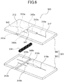
- FIG. 6 is a schematic disassembled view illustrating the flow path structure in this embodiment.
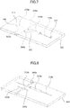
- FIG. 7 is a schematic perspective view illustrating a first plate member in this embodiment.
- FIG. 8 is a schematic perspective view illustrating a second plate member in this embodiment.
- FIG. 9 is a schematic perspective view illustrating a flow path switch member in this embodiment.
- the flow path structure 300 illustrated in FIG. 5 and FIG. 6 has the base 301, and the flow path switch member 330.
- the base 301 has a first plate member 302 and a second plate member 303, and the first plate member 302 and the second plate member 303 are laminated to form a laminated body.
- Each of the first plate member 302 and the second plate member 303 is made of a transparent material. In other words, each of the first plate member 302 and the second plate member 303 has transparency with respect to a wavelength region of the measuring light. Examples of the transparent material include glass, acrylic resin materials, cycloolefin resin materials, polyester resin materials, or the like.
- At least one of the first plate member 302 and the second plate member 303 is preferably made of a cycloolefin resin material, and both of the first plate member 302 and the second plate member 303 are more preferably made of the cycloolefin resin material.
- the base 301 has the separation element accommodation part 310, a first supply flow path 313, and a first discharge flow path 316. More particularly, as illustrated in FIG. 6 and FIG. 7 , the first plate member 302 is provided with a part 310a of the separation element accommodation part 310, a part 313a of the first supply flow path 313, and a part 316a of the first discharge flow path 316. On the other hand, as illustrated in FIG. 6 and FIG. 8 , the second plate member 303 is provided with a part 310b of the separation element accommodation part 310, a part 313b of the first supply flow path 313, and a part 316b of the first discharge flow path 316. By laminating the first plate member 302 and the second plate member 302 together, the separation element accommodation part 310, the first supply flow path 313, and the first discharge flow path 316 are formed on the base 301.
- Both ends of the separation element accommodation part 310 are formed as open ends 314 and 315.
- the separation element 311 is accommodated within the separation element accommodation part 310 between the two open ends 314 and 315.
- One end part of the first supply flow path 313 is formed as an opening 312.
- the other end part of the first supply flow path 313 is connected to one open end 314 of the separation element accommodation part 310.
- the first supply flow path 313 is connected to the supply pipe 11 (refer to FIG. 1 ) of the measuring device 10, and guides the developer solution 111 supplied through the supply pipe 11 of the measuring device 10 to the inside of the flow path structure 300 through the opening 312.
- One end part of the first discharge flow path 316 is connected to the other open end 315 of the separation element accommodation part 310.
- the other end part of the first discharge flow path 316 is formed as an opening 317.
- the first discharge flow path 316 discharges the developer solution 111 that passes through the separation element 311, the liquid 211 to be measured, or the mixture of the developer solution 111 and the liquid 211 to be measured, through the opening 317 to the outside of the flow path structure 300.
- the flow path switch member 330 has a flow path switch body 331.
- the flow path switch body 331 has a rectangular parallelepiped shape.
- the material forming the flow path switch body 331 is the same as the material forming the base 301.
- the material forming the flow path switch body 331 does not necessarily be the same as the material forming the base 301.
- the flow path switch body 331 has a first flow path 333, a second flow path 334, and a third flow path 335.
- Each of the first flow path 333, the second flow path 334, and the third flow path 335 penetrates the flow path switch body 331. In other words, both ends of each of the first flow path 333, the second flow path 334, and the third flow path 335 are formed as openings.
- the developer solution 111 flowing through the first supply flow path 313 passes through the one of the first flow path 333, the second flow path 334, and the third flow path 335 connected to the first supply flow path 313, and flows through the separation element 311 and the first discharge flow path 316.
- the developer solution 111 that is stored in the storage part 110 passes through the opening 312 to flow through the first supply flow path 313, passes through the flow path switch member 330, and flows through the separation element 311 and the first discharge flow path 316, to be discharged from the opening 317.
- the base 301 has a flow path switch member accommodation part 340, a second supply flow path 343, and a second discharge path 346. More particularly, as illustrated in FIG. 6 and FIG. 7 , the first plate member 302 is provided with a part 340a of the flow path switch member accommodation part 340, a part 343a of the second supply flow path 343, and a part 346a of the second discharge flow path 346. On the other hand, as illustrated in FIG. 6 and FIG. 8 , the second plate member 303 is provided with a part 340b of the flow path switch member accommodation part 340, a part 343b of the second supply flow path 343, and a part 346b of the second discharge flow path 346. By laminating the first plate member 302 and the second plate member 302 together, the flow path switch member accommodation part 340, the second supply flow path 343, and the second discharge flow path 346 are formed on the base 301.
- the flow path switch member accommodation part 340 extends in a direction parallel to a principal plane 301a of the base 301, and is provided at an intermediate part of the flow path that guides the liquid 211 to be measured to the separation element accommodation part 310.
- the flow path switch member accommodation part 340 traverses between the first supply flow path 313 and the second supply flow path 343.
- the flow path switch member 330 moves linearly in a direction intersecting the first supply flow path 313 and the second supply flow path 343.
- the flow path switch member 330 is accommodated within the flow path switch member accommodation part 340, and is movable (more particularly, slide) inside the flow path switch member accommodation part 340 in a direction in which the flow path switch member accommodation part 340 extends.
- the second supply flow path 343 is arranged side by side with the first supply flow path 313 in a direction parallel to the principal plane 301a of the base 301.
- the second discharge flow path 346 is arranged side by side with the first discharge flow path 316 in a direction parallel to the principal plane 301a of the base 301.
- One end part of the second supply flow path 343 is formed as an opening 342.
- the other end part of the second supply flow path 343 is connected to the flow path switch member accommodation part 340.
- the second supply flow path 343 guides the liquid 211 to be measured, that is supplied from the tank 210, to the inside of the flow path structure 300 through the opening 342.
- One end part of the second discharge flow path 346 is connected to the flow path switch member accommodation part 340.
- the other end part of the second discharge flow path 346 is formed as an opening 347.
- the second discharge flow path 346 discharges the liquid 211 to be measured, that passes through the flow path switch member 330, through the opening 347 to the outside of the flow path structure 300.
- the liquid 211 to be measured that passes through the second supply flow path 343, passes through the one of the first flow path 333, the second flow path 334, and the third flow path 335 connected to the second supply flow path 343, and flows through the second discharge flow path 346.
- the liquid 211 to be measured that is supplied from the tank 210, flows to the second supply flow path 343 through the opening 342, and passes through the flow path switch member 330, and flows to the second discharge flow path 346, to be discharged through the opening 347.
- the flow path switch body 331 does not necessarily have to include the third flow path 335.
- FIG. 10 is a schematic perspective view illustrating a case in which the flow path of the flow path structure in this embodiment is in the first flow path state.
- FIG. 11 is a schematic perspective view illustrating a case in which the flow path of the flow path structure in this embodiment is in the second flow path state.
- the flow path switch member 330 sets the state of the flow path of the flow path structure 300 to the first flow path state.
- the pump 120 is driven, and the developer solution 111 inside the storage part 110 is guided to the first supply flow path 313 through the opening 312. Then, as indicated by the arrow A22 illustrated in FIG. 10 , the developer solution 111 flows through the first flow path 333 of the flow path switch member 330, the separation element 311, and the first discharge flow path 316, and is discharged from the opening 317.
- a pressure fluctuation is applied to the inside of the tank 210, and the liquid 211 to be measured, inside the tank 210, is guided to the second supply flow path 343 through the opening 342. Then, as indicated by the arrow A24 illustrated in FIG. 10 , the liquid 211 to be measured flows through the second flow path 334 of the flow path switch member 330 and the second discharge flow path 346, and is discharged from the opening 347. For this reason, in the first flow path state, the second flow path 334 is filled by the liquid 211 to be measured.
- the pump 120 is stopped, and the flow path switch member 330 is moved.
- the openings at both ends of the second flow path 334 of the flow path switch member 330 are closed by sliding surfaces 341 opposing the flow path switch member 330.
- a closed space is formed by the second flow path 334 and the sliding surfaces 341.
- the liquid 211 to be measured, flowing through the second flow path 334 is temporarily held in the closed space that is formed by the second flow path 334 and the sliding surfaces 341, to be separated from other liquids.
- a volume of the second flow path 334 of the flow path switch member 330 does not change and is constant. For this reason, the flow path switch member 330 can measure the liquid 211 to be measured, flowing through the second flow path 334. In other words, the measurement of the liquid 211 to be measured is performed in the second flow path 334 of the flow path switch member 330.
- the second flow path 334 of the flow path switch member 330 corresponds to a sample measuring part that measures the liquid 211 to be measured.
- the second flow path 334 is connected to the first supply flow path 313.
- the third flow path 335 of the flow path switch member 330 is connected to the second supply flow path 343 and the second discharge flow path 346.
- the flow path switch member 330 switches the state of the flow path of the flow path structure 300 from the first flow path state to the second flow path state. Thereafter, the pump 120 is driven again.
- the measured amount of the liquid 211 to be measured is guided to the inside of the separation element accommodation part 310 in association with the flow of the developer solution 111. More particularly, the liquid 211 to be measured, that is temporarily held in the closed space formed by the second flow path 334 of the flow path switch member 330 and the sliding surfaces 341, and is measured in the second flow path 334 of the flow path switch member 330, is mixed with the developer solution 111 and guided to the inside of the separation element accommodation part 310.
- the flow path switch member 330 functions as a flow path switching part and the sample measuring part.
- the mixture of the measured liquid 211 and the developer solution 111 is supplied to the separation element 311.
- the separation of the liquid 211 to be measured is performed.
- the mixture of the liquid 211 to be measured and the developer solution 111 flows through the first discharge flow path 316 and is discharged from the opening 317.
- the detector part 430 obtains the information related to the composition of the liquid 211 to be measured.
- the flow path structure 300 in this embodiment it is possible to reduce the number of parts of the sample introduction part 200 (refer to FIG. 1 ) of the measuring device 10, because the flow path switch member 330 is provided on the base 301. For this reason, the measuring device 10 in this embodiment can be used with ease. In addition, the flow path switch member 330 can be changed after performing the measurement one or a plurality of times. Consequently, it is easy to attend to the maintenance of the measuring device 10.
- the information related to the composition of the liquid 211 to be measured can be measured with a high sensitivity.
- the flow path switch member 330 in this embodiment has the third flow path 335.
- the third flow path 335 is connected to the second supply flow path 343 and the second discharge flow path 346 when the liquid 211 to be measured is introduced to the inside of the separation element accommodation part 310. For this reason, even when the measured liquid 211 is introduced to the inside of the separation element accommodation part 310, the liquid 211 to be measured, that is supplied from the tank 210, flows through the second supply flow path 343, and is guided to the second discharge flow path 346 through the third flow path 335 of the flow path switch member 330. In other words, when the measured liquid 211 is introduced to the inside of the separation element accommodation part 310, the third flow path 335 guides the liquid 211 to be measured, that is supplied from the tank 210, to the second discharge flow path 346.
- the measured liquid 211 is guided to the inside of the separation element accommodation part 310, it is possible to reduce a cutoff in the flow path of the liquid 211 to be measured, that is supplied from the tank 210.
- the measured liquid 211 is introduced to the inside of the separation element accommodation part 310, it is possible to reduce a liquid leak.
- it is possible to reduce the cutoff of the flow path of the liquid 211 to be measured, that is supplied from the tank 210 it is possible to reduce a pressure rise inside the flow path connected to the tank 210. Accordingly, even in a case in which a pump that is not illustrated is provided to apply the pressure fluctuation to the inside of the tank 210, it is possible to reduce damage to this pump.
- FIG. 12 is a schematic perspective view illustrating another flow path structure in this embodiment.
- FIG. 13 is a schematic cross sectional view illustrating the other flow path structure in this embodiment.
- FIG. 14 is a schematic disassembled view illustrating the other flow path structure in this embodiment.
- FIG. 15 is a schematic perspective view illustrating the first plate member in this embodiment.
- FIG. 16 is a schematic perspective view illustrating the second plate member in this embodiment.
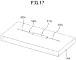
- FIG. 17 is a schematic perspective view illustrating a third plate member in this embodiment.
- FIG. 18 is a schematic perspective view illustrating the flow path switch member in this embodiment.
- FIG. 13 is the schematic cross sectional view along a cutting plane A-A illustrated in FIG. 12 .
- a flow path structure 300 illustrated in FIG. 12 through FIG. 14 has the base 301, and the flow path switch part 330.
- the base 301 has the first plate member 302, the second plate member 303, and the third plate member 304.
- the first plate member 302, the second plate member 303, and the third plate member 304 are laminated to form the laminated body.
- the materials forming the first plate member 302, the second plate member 303, and the third plate member 304 are the same as the materials forming the first plate member 302 and the second plate member 303 described above with reference to FIG. 5 through FIG. 11 .
- the first supply flow path 313 is arranged side by side with the second supply flow path 343 in a direction intersecting the principal plane 301a of the base 301.
- the first supply flow path 313 is arranged side by side with the second supply flow path 343 in a direction perpendicular to the principal plane 301a of the base 301.
- the first discharge flow path 316 is arranged side by side with the second discharge flow path 346 in a direction perpendicular to the principal plane 301a of the base 301.
- the first plate member 302 is provided with the part 340a of the flow path switch member accommodation part 340, the part 313a of the first supply flow path 313, the part 316a of the first discharge flow path 316, the part 343a of the second supply flow path 343, and the part 346a of the second discharge flow path 346.
- the second plate member 303 is provided with the part 340b of the flow path switch member accommodation part 340, the part 310b of the separation element accommodation part 310, the part 313b of the first supply flow path 313, the part 316b of the first discharge flow path 316, the part 343b of the second supply flow path 343, and the part 346b of the second discharge flow path 346.
- the third plate member 304 is provided with a part 340c of the flow path switch member accommodation part 340, a part 310c of the separation element accommodation part 310, a part 313c of the first supply flow path 313, and a part 316c of the first discharge flow path 316.
- the flow path switch member accommodation part 340, the separation element accommodation part 310, the first supply flow path 313, the first discharge flow path 316, the second supply flow path 343, and the second discharge flow path 346 are formed on the base 301.
- the second supply flow path 343 and the second discharge flow path 346 are provided on an upper side of the separation element accommodation part 310, the first supply flow path 313, and the first discharge flow path 316.
- an upward direction refers to a direction perpendicular to the principal plane 301a of the base 301, that is towards the first plate member 302 when viewed from the third plate member 304.
- a downward direction refers to a direction perpendicular to the principal plane 301a of the base 301, that is towards the third plate member 304 when viewed from the first plate member 302.
- the flow path switch member accommodation part 340 extends in the direction intersecting the principal plane 301a of the base 301, and is provided at an intermediate part of the flow path that guides the liquid 211 to be measured to the separation element accommodation part 310.
- the flow path switch member accommodation part 340 extends in the direction (direction of plate thickness) perpendicular to the principal plane 301a of the base 301, and traverses between the first supply flow path 313 and the second supply flow path 343.
- the flow path switch member 330 moves linearly in the direction intersecting the first supply flow path 313 and the second supply flow path 343.
- the flow path switch member 330 is accommodated within the flow path switch member accommodation part 340, and can move (more particularly, slidable) inside the flow path switch member accommodation part 340 in the direction in which the flow path switch member accommodation part 340 extends. In other words, the flow path switch member 330 can move in the direction of the plate thickness of the base 301.
- the flow path switch member 330 has the flow path switch body 331.
- the flow path switch body 331 has a parallelepiped shape.
- the flow path switch body 331 has the first flow path 333, the second flow path 334, and the third flow path 335.
- Each of the first flow path 333, the second flow path 334, and the third flow path 335 penetrates the flow path switch body 331. In other words, both ends of each of the first flow path 333, the second flow path 334, and the third flow path 335 are formed as openings.
- the structure of the flow path structure 300 other than the above is similar to the structure of the flow path structure 300 described above in conjunction with FIG. 5 through FIG. 9 .
- FIG. 19 is a schematic perspective view illustrating the case in which the flow path of the flow path structure in this embodiment is in the first flow path state.
- FIG. 20 is a schematic perspective view illustrating the case in which the flow path of the flow path structure in this embodiment is in the second flow path state.
- the flow path switch member 330 sets the state of the flow path of the flow path structure 300 to the first flow path state.
- the pump 120 is driven, and the developer solution 111 inside the storage part 110 is guided to the first supply flow path 313 through the opening 312. Then, as indicated by the arrow A22 illustrated in FIG. 19 , the developer solution 111 flows through the first flow path 333 of the flow path switch member 330, the separation element 311, and the first discharge flow path 316, and is discharged from the opening 317.
- the pressure fluctuation is applied to the inside of the tank 210, and the liquid 211 to be measured, inside the tank 210, is guided to the second supply flow path 343 through the opening 342. Then, as indicated by the arrow A24 illustrated in FIG. 19 , the liquid 211 to be measured flows through the second flow path 334 of the flow path switch member 330 and the second discharge flow path 346, and is discharged from the opening 347. For this reason, in the first flow path state, the second flow path 334 is filled by the liquid 211 to be measured.
- the pump 120 is stopped, and the flow path switch member 330 is moved.
- the openings at both ends of the second flow path 334 of the flow path switch member 330 are closed by the sliding surfaces 341 opposing the flow path switch member 330.
- the closed space is formed by the second flow path 334 and the sliding surfaces 341.
- the liquid 211 to be measured, flowing through the second flow path 334 is temporarily held in the closed space that is formed by the second flow path 334 and the sliding surfaces 341, to be separated from other liquids.
- the volume of the second flow path 334 of the flow path switch member 330 does not change and is constant. For this reason, the flow path switch member 330 can measure the liquid 211 to be measured, flowing through the second flow path 334. In other words, the measurement of the liquid 211 to be measured is performed in the second flow path 334 of the flow path switch member 330.
- the second flow path 334 of the flow path switch member 330 corresponds to the sample measuring part that measures the liquid 211 to be measured.
- the second flow path 334 is connected to the first supply flow path 313.
- the third flow path 335 of the flow path switch member 330 is connected to the second supply flow path 343 and the second discharge flow path 346.
- the flow path switch member 330 switches the state of the flow path of the flow path structure 300 from the first flow path state to the second flow path state. Thereafter, the pump 120 is driven again.
- the measured amount of the liquid 211 to be measured is guided to the inside of the separation element accommodation part 310 in association with the flow of the developer solution 111. More particularly, the liquid 211 to be measured, that is temporarily held in the closed space formed by the second flow path 334 of the flow path switch member 330 and the sliding surfaces 341, and is measured in the second flow path 334 of the flow path switch member 330, is mixed with the developer solution 111 and guided to the inside of the separation element accommodation part 310.
- the flow path switch member 330 functions as the flow path switching part and the sample measuring part.
- the mixture of the measured liquid 211 and the developer solution 111 is supplied to the separation element 311.
- the separation of the liquid 211 to be measured is performed.
- the mixture of the liquid 211 to be measured and the developer solution 111 flows through the first discharge flow path 316 and is discharged from the opening 317.
- the detector part 430 obtains the information related to the composition of the liquid 211 to be measured.
- the flow path switch member 330 guides the liquid 211 to be measured, that is measured in the second flow path 334, to the inside of the separation element accommodation part 310, by moving in the direction of the plate thickness of the base 301. For this reason, it is possible to further reduce the size of the flow path structure 300 in the direction parallel to the principal plane 301a of the base 301. In addition, it is possible to obtain effects similar to the effects described above in conjunction with FIG. 5 through FIG. 11 .
- FIG. 21 is a schematic perspective view illustrating still another flow path structure in this embodiment.
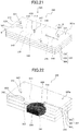
- FIG. 22 is a schematic cross sectional view illustrating the still other flow path structure in this embodiment.
- FIG. 23 is a schematic plan view illustrating the still other flow path structure in this embodiment.
- FIG. 24 is a schematic disassembled view illustrating the still other flow path structure in this embodiment.
- FIG. 25 is a schematic perspective view illustrating the first plate member in this embodiment.
- FIG. 26 is a schematic perspective view illustrating the second plate member in this embodiment.
- FIG. 27 is a schematic perspective view illustrating the third plate member in this embodiment.
- FIG. 28 is a schematic perspective view illustrating the flow path switch member in this embodiment.
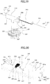
- FIG. 29 is a schematic perspective view illustrating only a flow path part in this embodiment.
- FIG. 22 is a right-angled cross sectional view along a cutting plane B-O-B illustrated in FIG. 21 .
- FIG. 23 is a schematic plan view when a flow path structure 300 in this embodiment is viewed in the direction of an arrow A26 in FIG. 21 .
- the flow path structure 300 illustrated in FIG. 21 through FIG. 24 has the base 301, and the flow path switch member 330.
- the base 301 has the first plate member 302, the second plate member 303, and the third plate member 304.
- the first plate member 302, the second plate member 303, and the third plate member 304 are laminated to form the laminated body.
- the materials forming the first plate member 302, the second plate member 303, and the third plate member 304 are the same as the materials forming the first plate member 302 and the second plate member 303 described above with reference to FIG. 5 through FIG. 11 .
- the first supply flow path 313 is arranged side by side with the second supply flow path 343 in the direction parallel to the principal plane 301a of the base 301, similarly as in the case of the flow path structure 300 described above with reference to FIG. 5 through FIG. 11 .
- the first discharge flow path 316 is arranged side by side with the second discharge flow path 346 in the direction parallel to the principal plane 301a of the base 301.
- the first plate member 302 is provided with the part 313a of the first supply flow path 313, the part 316a of the first discharge flow path 316, the part 343a of the second supply flow path 343, and the part 346a of the second discharge flow path 346.
- the second plate member 303 is provided with the part 310b of the separation element accommodation part 310, the part 313b of the first supply flow path 313, the part 316b of the first discharge flow path 316, the part 343b of the second supply flow path 343, and the part 346b of the second discharge flow path 346.
- the third plate member 304 is provided with the flow path switch member accommodation part 340.
- the flow path switch member accommodation part 340 is formed as a hole having a cylindrical shape, and is provided at the intermediate part of the flow path that guides the liquid 211 to be measured to the separation element accommodation part 310.
- the flow path switch member accommodation part 340 illustrated in FIG. 24 and FIG. 27 penetrates the third plate member 304 in the direction of the plate thickness.
- a center axis C2 of the cylindrical hole forming the flow path switch member accommodation part 340 extends in a direction intersecting a principal plane 304a of the third plate member 304.
- the center axis C2 of the cylindrical hole forming the flow path switch member accommodation part 340 extends in a direction perpendicular to the principal plane 304a of the third plate member 304.
- the flow path switch member accommodation part 340 does not necessarily have to penetrate the third plate member 304 in the direction of the plate thickness.
- the separation element accommodation part 310, the first supply flow path 313, the first discharge flow path 316, the second supply flow path 343, and the second discharge flow path 346 are formed on the base 301.
- the flow path switch member 330 has the flow path switch body 331.
- the flow path switch body 331 in this embodiment corresponds to a rotor, and has a cylindrical shape, for example.
- the flow path switch body 331 in this embodiment simply needs to function as a rotor that is rotatable, and may have the cylindrical shape at a part of the flow path switch body 331.
- the flow path switch body 331 has the first flow path 333, and the second flow path 334. Each of the first flow path 333 and the second flow path 334 is provided on a principal plane 331a of the flow path switch body 331.
- the flow path switch member 330 is accommodated within the flow path switch member accommodation part 340 in a state in which the principal plane 331a provided with the first flow path 333 and the second flow path 334 faces towards the second plate member 303.
- the flow path switch member 330 is accommodated within the flow path switch member accommodation part 340 in the state in which a center axis C1 of the rotor extends in a direction intersecting the principal plane 304a of the third plate member 304.
- the flow path switch member 330 is accommodated within the flow path switch member accommodation part 340 in the state in which the center axis C1 of the rotor extends in a direction perpendicular to the principal plane 304a of the third plate member 304.
- the flow path switch member 330 is accommodated within the flow path switch member accommodation part 340 in the state in which the center axis C1 of the rotor is parallel to the center axis C2 of the cylindrical hole forming the flow path switch member accommodation part 340.
- the first plate member 302, the second plate member 303, and the third plate member 304 are mutually laminated in the state in which the flow path switch member 330 is accommodated within the flow path switch member accommodation part 340, the first flow path 333 is connected to the first supply flow path 313, and one of the second supply flow path 343 and the second discharge flow path 346.
- the second flow path 334 is connected to the first supply flow path 313, and the other of the second supply flow path 343 and the second discharge flow path 346.
- the flow path switch member 330 can rotate inside the flow path switch member accommodation part 340 using the center axis C1 of the rotor as a rotation center.
- the first flow path 333 is connected to the first supply flow path 313, or to the second supply flow path 343 and the second discharge flow path 346.
- the second flow path 334 is connected to the second supply flow path 343 and the second discharge flow path 346, or the first supply flow path 313.
- the structure of the flow path structure 300 other than the above is similar to the structure of the flow path structure 300 described above in conjunction with FIG. 5 through FIG. 9 .
- the flow path switch member 330 sets the state of the flow path of the flow path structure 300 to the first flow path state.
- the pump 120 is driven, and the developer solution 111 inside the storage part 110 is guided to the first supply flow path 313 through the opening 312. Then, as indicated by the arrow A22 illustrated in FIG. 29 , the developer solution 111 flows through the first flow path 333 of the flow path switch member 330, the separation element 311, and the first discharge flow path 316, and is discharged from the opening 317.
- the pressure fluctuation is applied to the inside of the tank 210, and the liquid 211 to be measured, inside the tank 210, is guided to the second supply flow path 343 through the opening 342. Then, as indicated by the arrow A24 illustrated in FIG. 29 , the liquid 211 to be measured flows through the second flow path 334 of the flow path switch member 330 and the second discharge flow path 346, and is discharged from the opening 347. For this reason, in the first flow path state, the second flow path 334 is filled by the liquid 211 to be measured.
- the pump 120 is stopped, and the flow path switch member 330 is rotated inside the flow path switch member accommodation part 340. Then, when the state of the flow path inside the base 301 makes a transition from the first flow path state to the second flow path state, the openings at both ends of the second flow path 334 of the flow path switch member 330 is closed by the sliding surfaces 341 opposing the flow path switch member 330. Hence, the closed space is formed by the second flow path 334 and the sliding surfaces 341. For this reason, the liquid 211 to be measured, flowing through the second flow path 334, is temporarily held in the closed space that is formed by the second flow path 334 and the sliding surfaces 341, to be separated from other liquids.
- the volume of the second flow path 334 of the flow path switch member 330 does not change and is constant. For this reason, the flow path switch member 330 can measure the liquid 211 to be measured, flowing through the second flow path 334. In other words, the measurement of the liquid 211 to be measured is performed in the second flow path 334 of the flow path switch member 330.
- the second flow path 334 of the flow path switch member 330 corresponds to the sample measuring part that measures the liquid 211 to be measured.
- the second flow path 334 of the flow path switch member 330 is connected to the first supply flow path 313.
- the first flow path 333 of the flow path switch member 330 is connected to the second supply flow path 343 and the second discharge flow path 346.
- the flow path switch member 330 switches the state of the flow path of the flow path structure 300 from the first flow path state to the second flow path state. Thereafter, the pump 120 is driven again.
- the measured amount of the liquid 211 to be measured is guided to the inside of the separation element accommodation part 310 in association with the flow of the developer solution 111. More particularly, the liquid 211 to be measured, that is temporarily held in the closed space formed by the second flow path 334 of the flow path switch member 330 and the sliding surfaces 341, and is measured in the second flow path 334 of the flow path switch member 330, is mixed with the developer solution 111 and guided to the inside of the separation element accommodation part 310.
- the flow path switch member 330 functions as the flow path switching part and the sample measuring part.
- the mixture of the measured liquid 211 and the developer solution 111 is supplied to the separation element 311.
- the separation of the liquid 211 to be measured is performed.
- the mixture of the liquid 211 to be measured and the developer solution 111 flows through the first discharge flow path 316 and is discharged from the opening 317.
- the detector part 430 obtains the information related to the composition of the liquid 211 to be measured.
- the flow path switch member 330 corresponds to the rotor having the cylindrical shape, for example, and rotates using the center axis C1 of the rotor as the rotation center, to introduce the liquid 211 to be measured, that is measured in the second flow path 334, to the inside of the separation element accommodation part 310. For this reason, it is possible to reduce the size of the flow path switch member 330, and to further reduce the size of the flow path structure 300. In addition, it is possible to obtain effects similar to the effects described above in conjunction with FIG. 5 through FIG. 11 .
- FIG. 30 is a schematic perspective view illustrating a still yet another flow path structure in this embodiment.
- FIG. 31 is a schematic cross sectional view illustrating the still yet another flow path structure in this embodiment.
- FIG. 32 is a schematic disassembled view illustrating the still yet another flow path structure in this embodiment.
- FIG. 33 is a schematic plan view illustrating the still yet another flow path structure in this embodiment.
- FIG. 34 is a schematic perspective view illustrating the first plate member in this embodiment.
- FIG. 35 is a schematic perspective view illustrating the second plate member in this embodiment.
- FIG. 36 is a schematic perspective view illustrating the flow path switch member in this embodiment.
- FIG. 31 is a right-angled cross sectional view along a cutting plane C-O-C illustrated in FIG. 30 .
- FIG. 33 is a schematic plan view when a flow path structure 300 in this embodiment is viewed in the direction of an arrow A28 in FIG. 30 .
- a flow path structure 300 illustrated in FIG. 30 through FIG. 33 has the base 301, and the flow path switch part 330.
- the base 301 has the first plate member 302, and the second plate member 303.
- the first plate member 302 and the second plate member 303 are laminated to form the laminated body.
- the materials forming the first plate member 302 and the second plate member are the same as the materials forming the first plate member 302 and the second plate member 303 described above with reference to FIG. 5 through FIG. 11 .
- the base 301 has the separation element accommodation part 310, the first supply flow path 313, the first discharge flow path 316, the second supply flow path 343, and the second discharge flow path 346. Structures of each of the separation element accommodation part 310, the first supply flow path 313, the first discharge flow path 316, the second supply flow path 343, and the second discharge flow path 346 are the same as the structures of each of the separation element accommodation part 310, the first supply flow path 313, the first discharge flow path 316, the second supply flow path 343, and the second discharge flow path 346 described above with reference to FIG. 5 through FIG. 11 .
- the base 301 has the flow path switch member accommodation part 340.
- the flow path switch member accommodation part 340 is provided at an intermediate part of the flow path that guides the liquid 211 to be measured to the separation element accommodation part 310.
- the flow path switch member accommodation part 340 traverses the first supply flow path 313 and the second supply flow path 343. More particularly, as illustrated in FIG. 32 and FIG. 34 , the first plate member 302 is provided with the part 340a of the flow path switch member accommodation part 340. As illustrated in FIG. 32 and FIG. 35 , the second plate member 303 is provided with the part 340b of the flow path switch member accommodation part 340. By laminating the first plate member 302 and the second plate member 303 together, the flow path switch member accommodation part 340 is formed on the base 301.
- the flow path switch member 330 has the flow path switch body 331.
- the flow path switch body 331 in this embodiment corresponds to the rotor, and has the cylindrical shape, for example. In other words, the flow path switch body 331 in this embodiment simply needs to function as the rotor that is rotatable, and may have the cylindrical shape at a part of the flow path switch body 331.
- the flow path switch body 331 has the first flow path 333, and the second flow path 334. Each of the first flow path 333 and the second flow path 334 penetrates the flow path switch body 331 in a direction parallel to the center axis C1 of the rotor. In other words, both ends of each of the first flow path 333 and the second flow path 334 are formed as openings.
- the flow path switch member 330 is held by the flow path switch member accommodation part 340 in a state in which the center axis C1 of the rotor extends in a direction parallel to the principal plane 301a of the base 301.
- the flow path switch member 330 can rotate using the center axis C1 of the rotor as a rotation center, in a state held by the flow path switch member accommodation part 340.
- the first flow path 333 is connected to the first supply flow path 313, or to the second supply flow path 343 and the second discharge flow path 346.
- the second flow path 334 is connected to the second supply flow path 343 and the second discharge flow path 346, or the first supply flow path 313.
- the structure of the flow path structure 300 other than the above is similar to the structure of the flow path structure 300 described above in conjunction with FIG. 5 through FIG. 9 .
- the first flow path 333 of the flow path switch member 330 is connected to the first supply flow path 313.
- the second flow path 334 of the flow path switch member 330 is connected to the second supply flow path 343 and the second discharge flow path 346.
- the flow path switch member 330 sets the state of the flow path of the flow path structure 300 to the first flow path state.
- the pump 120 is driven, and the developer solution 111 inside the storage part 110 is guided to the first supply flow path 313 through the opening 312. Then, as indicated by the arrow A22 illustrated in FIG. 30 , the developer solution 111 flows through the first flow path 333 of the flow path switch member 330, the separation element 311, and the first discharge flow path 316, and is discharged from the opening 317.
- the pressure fluctuation is applied to the inside of the tank 210, and the liquid 211 to be measured, inside the tank 210, is guided to the second supply flow path 343 through the opening 342. Then, as indicated by the arrow A24 illustrated in FIG. 30 , the liquid 211 to be measured flows through the second flow path 334 of the flow path switch member 330 and the second discharge flow path 346, and is discharged from the opening 347. For this reason, in the first flow path state, the second flow path 334 is filled by the liquid 211 to be measured.
- the pump 120 is stopped, and the flow path switch member 330 is rotated.
- the openings at both ends of the second flow path 334 of the flow path switch member 330 are closed by the sliding surfaces 341 (refer to FIG. 32 ) opposing the flow path switch member 330.
- the closed space is formed by the second flow path 334 and the sliding surfaces 341.
- the liquid 211 to be measured, flowing through the second flow path 334 is temporarily held in the closed space that is formed by the second flow path 334 and the sliding surfaces 341, to be separated from other liquids.
- the volume of the second flow path 334 of the flow path switch member 330 does not change and is constant. For this reason, the flow path switch member 330 can measure the liquid 211 to be measured, flowing through the second flow path 334. In other words, the measurement of the liquid 211 to be measured is performed in the second flow path 334 of the flow path switch member 330.
- the second flow path 334 of the flow path switch member 330 corresponds to the sample measuring part that measures the liquid 211 to be measured.
- the second flow path 334 of the flow path switch member 330 is connected to the first supply flow path 313.
- the first flow path 333 of the flow path switch member 330 is connected to the second supply flow path 343 and the second discharge flow path 346.
- the flow path switch member 330 switches the state of the flow path of the flow path structure 300 from the first flow path state to the second flow path state. Thereafter, the pump 120 is driven again.
- the measured amount of the liquid 211 to be measured is guided to the inside of the separation element accommodation part 310 in association with the flow of the developer solution 111. More particularly, the liquid 211 to be measured, that is temporarily held in the closed space formed by the second flow path 334 of the flow path switch member 330 and the sliding surfaces 341, and is measured in the second flow path 334 of the flow path switch member 330, is mixed with the developer solution 111 and guided to the inside of the separation element accommodation part 310.
- the flow path switch member 330 functions as the flow path switching part and the sample measuring part.
- the mixture of the measured liquid 211 and the developer solution 111 is supplied to the separation element 311.
- the separation of the liquid 211 to be measured is performed.
- the mixture of the liquid 211 to be measured and the developer solution 111 flows through the first discharge flow path 316 and is discharged from the opening 317.
- the detector part 430 obtains the information related to the composition of the liquid 211 to be measured.
- the flow path switch member 330 corresponds to the rotor having the cylindrical shape, for example, and rotates using the center axis C1 of the rotor as the rotation center, to introduce the liquid 211 to be measured, that is measured in the second flow path 334, to the inside of the separation element accommodation part 310. For this reason, it is possible to reduce the size of the flow path switch member 330, and to further reduce the size of the flow path structure 300. In addition, it is possible to obtain effects similar to the effects described above in conjunction with FIG. 5 through FIG. 11 .
- the particular structures of the measuring devices described above may be appropriately set according to the structure of the flow path structure, a type of liquid to be measured, or the like.
- the storage part 110 of the liquid supply part 100 may be provided in the flow path structure 300.
- the separation element may be an electrophoretic element.
- the flow path structure has an electrode part inside the flow path, and this electrode part is made electrically connectable to the measuring device.
Landscapes
- Chemical & Material Sciences (AREA)
- Health & Medical Sciences (AREA)
- Analytical Chemistry (AREA)
- Life Sciences & Earth Sciences (AREA)
- Physics & Mathematics (AREA)
- General Health & Medical Sciences (AREA)
- Biochemistry (AREA)
- General Physics & Mathematics (AREA)
- Immunology (AREA)
- Pathology (AREA)
- Chemical Kinetics & Catalysis (AREA)
- Molecular Biology (AREA)
- Engineering & Computer Science (AREA)
- Nanotechnology (AREA)
- Spectroscopy & Molecular Physics (AREA)
- Electrochemistry (AREA)
- Dispersion Chemistry (AREA)
- Hematology (AREA)
- Clinical Laboratory Science (AREA)
- Automatic Analysis And Handling Materials Therefor (AREA)
Abstract
Description
- The present invention relates to a flow path structure that is used in a measuring device for a liquid to be measured, and the measuring device for the liquid to be measured and having the flow path structure incorporated into the measuring device.
- In a case in which a measurement is made to obtain information related to a composition of a liquid to be measured, HPLC (High Performance Liquid Chromatography) devices are used, for example.
- Regarding the HPLC devices, Patent Document 1 describes a HPLC device having a column, a liquid supply part, a sample introduction part, a detector part, a controller part, a drain port, a first flow path selector valve, and a second flow path selector valve. Each of the first flow path selector valve and the second flow path selector valve has a plurality of flow path grooves, and is a 3-positoin valve that can select from 3 positions.
- The HPLC device described in Patent Document 1 can take a Load (sample input) position and an INJ/Purge in (sample injection/measuring pump purge input) position, by controlling operations of the liquid supply part and the sample introduction part by the controller part.
- In the Load (sample input) position, a sampling needle of the sample introduction part is immersed into a sample container containing a sample, and a measuring pump of the sample introduction part performs an input operation. Hence, the sample is input to a sampling loop of the sample introduction part and sampled.
- In the INJ/Purge in (sample injection/- measuring pump purge input) position, a mobile phase passes the sampling loop, and flows in a flow path from the column and passing the detector part, through a connection point between the sampling needle and an injection port of the sample introduction part. In addition, the sample that is sampled in the sampling loop is supplied to the column, and separation of the sample starts at the column.
- Recently, POCT (Point-Of-Care Testing), that refers to simple and rapid tests or the like conducted by medical personnel at medical examination and nursing sites, is becoming popular. From a viewpoint of performing the POCT, the HPLC device is preferably simple to use. In addition, the HPLC device preferably has a small size.
- Patent Document 1: Japanese Laid-Open Patent Publication No.
2001-255316 - However, the sample introduction part of the HPLC device described in Patent Document 1 has a relatively large number of parts, and suffers from a problem in that it is difficult to use the HPLC device without expert knowledge of the HPLC device. In other words, there is a problem in that the HPLC device described in Patent Document 1 is not popular as a device for POCT that requires to be attended by general personnel having no expert knowledge. Further, because it is difficult to use the HPLC device, there is a problem in that it is difficult to attend to maintenance of the HPLC device.
- In addition, the HPLC device described in Patent Document 1 has relatively large members, such as a first flow path switch valve, a second flow path switch valve, or the like, and there is a problem in that it is difficult to reduce the size of the HPLC device.
- The present invention is conceived to solve the problems of the prior art described above. One object of the present invention is to provide a flow path structure to be incorporated into a measuring device that enables easy maintenance. In addition, one object of the present invention is to provide a flow path structure to be incorporated into a measuring device having a size that can be reduced. Another object of the present invention is to provide a measuring device for a liquid to be measured and having a flow path structure incorporated into the measuring device.
- In one embodiment of the present invention, a flow path structure includes a base that has a separation element accommodation part accommodating a separation element that separates a plurality of components included in a liquid to be measured, and a flow path switch member accommodation part provided at an intermediate part of a flow path that guides the liquid to be measured to the separation element accommodation part, and a flow path switch member provided in the flow path switch member accommodation part, and is characterized in that the flow path switch member switches a state of a flow path inside the base between a first flow path state in which the liquid to be measured is guided to an inside of the flow path switch member, and a second flow path state in which the liquid to be measured, guided to the inside of the flow path switch member, is guided to an inside of the separation element accommodation part, wherein the liquid to be measured, guided to the inside of the flow path switch member, is held and measured when the state of the flow path inside the base makes a transition from the first flow path state to the second flow path state.
- According to the flow path structure in one embodiment of the present invention, the flow path switch member switches the state of the flow path inside the base between the first flow path state in which the liquid to be measured is guided to the inside of the flow path switch member, and the second flow path state in which the liquid to be measured, guided to the inside of the flow path switch member, is guided to the inside of the separation element accommodation part. When the state of the flow path inside the base makes a transition from the first flow path state to the second flow path state, the flow path switch member holds the liquid to be measured, that is introduced inside the flow path switch member itself, to measure the liquid. Because the flow path structure has such a flow path switch member, it is possible to reduce the number of parts of the part where the liquid to be measured is introduced. For this reason, it is easy to use the measuring device that measures the liquid to be measured, and maintenance of the measuring device is facilitated. In addition, because it is possible to reduce the number of parts of the part where the liquid to be measured is introduced, it is possible to reduce the size of the measuring device.
- In addition, in order to measure information related to the composition of the liquid to be measured with a high sensitivity, it is preferable that a volume of a flow path, between a part where the liquid to be measured is measured, and the separation element accommodation part accommodating the separation element, is as small as possible. This is because the liquid to be measured diffuses in the flow path, when the flow path between the part where the liquid to be measured is measured and the separation element accommodation part accommodating the separation element has a large volume.
- On the other hand, according to the flow path structure in one embodiment of the present invention, the flow path structure includes the flow path switch member, and thus, the volume of the flow path between the part where the liquid to be measured is measured and the separation element accommodation part accommodating the separation element can be made small. Hence, the information related to the composition of the liquid to be measured can be measured with a high sensitivity.
- According to the flow path structure of the present invention, the base may further have a first supply flow path that guides a developer solution as a mobile phase to the separation element accommodation part, and a second supply flow path that guides the liquid to be measured, the flow path switch member may have a first flow path that guides the developer solution, and a second flow path that holds the liquid to be measured, in the first flow path state, the first flow path is connected to the first supply flow path, and the second flow path is connected to the second supply flow path, and in the second flow path state, the second flow path is connected to the first supply flow path.
- According to this flow path structure, the base includes the first supply flow path that guides the developer solution to the separation element accommodation part, and the second supply flow path that guides the liquid to be measured to the inside of the base. On the other hand, the flow path switch member includes the first flow path that guides the developer solution, and the second flow path that holds and measures the liquid to be measured. The flow path switch member in the first flow path state guides the liquid to be measured to the second flow path that is connected to the second supply flow path, and holds and measures the liquid to be measured in the second flow path when the flow path of the base makes the transition from the first flow path state to the second flow path state. Further, the flow path switch member in the second flow path state can guide the liquid to be measured, that is measured in the second flow path, to the inside of the separation element accommodation part, using the second flow path that is connected to the first supply flow path.
- According to the flow path structure of the present invention, the flow path switch member may be slidably provided inside the flow path switch member accommodation part, and when the flow path switch member slides inside the flow path switch member accommodation part and the state of the floe path inside the base makes the transition from the first flow path state to the second flow path state, openings at both ends of the second flow path may be closed by sliding surfaces opposing the flow path switch member, and the flow path switch member may hold and measure the liquid to be measured, guided to the second flow path.
- According to this flow path structure, when the flow path switch member slides inside the flow path switch member accommodation part and the state of the flow path inside the base makes the transition from the first flow path state to the second flow path state, the openings at both ends of the second flow path are closed by the sliding surfaces opposing the floe path switch member. Hence, a closed space is formed by the second flow path and the sliding surfaces. For this reason, the liquid to be measured, flowing through the second flow path, is temporarily held in the closed space formed by the second flow path and the sliding surfaces, to be separated from other liquids. Accordingly, the measurement of the
liquid 211 to be measured is performed in thesecond flow path 334 of the flowpath switch member 330. - According to the flow path structure of the present invention, the flow path switch member may move linearly in a direction intersecting the first supply flow path and the second supply flow path. According to this flow path structure, the flow path switch member can cause the state of the flow path inside the base to make the transition from the first flow path state to the second flow path state by a relatively simple movement.
- In the flow path structure of the present invention, the flow path switch member accommodation part may extend in a direction parallel to a principal plane of the base, and the flow path switch member may have a parallelepiped shape, and be movable inside the flow path switch member accommodation part along a direction in which the flow path switch member accommodation part extends. According to this flow path structure, the liquid to be measured, that is measured in the second flow path, can be guided to the inside of the separation element accommodation part, when the flow path switch member that has a relatively simple structure moves along the direction in which the flow path switch member accommodation part extends.
- In the flow path structure of the present invention, the flow path switch member accommodation part may extend in a direction intersecting a principal plane of the base, and the flow path switch member may have a parallelepiped shape, and be movable inside the flow path switch member accommodation part along a direction in which the flow path switch member accommodation part extends.
- According to this flow path structure, the flow path switch member can guide the liquid to be measured, that is measured in the second flow path, to the inside of the separation element accommodation part, by moving along the direction in which the flow path switch member accommodation part extends, that is, along the direction intersecting the principal plane of the base. For this reason, it is possible to further reduce the size of the flow path structure in the direction parallel to the principal plane of the base.
- In the flow path structure of the present invention, the flow path switch member may be connected to the second supply flow path in the second flow path state, and further include a third flow path that guides the liquid to be measured.
- According to this flow path structure, the third flow path is connected to the second supply flow path when the liquid to be measured, that is measured in the second flow path, is introduced to the inside of the separation element accommodation part. For this reason, even when the liquid to be measured, that is measured in the second flow path, is introduced to the inside of the separation element accommodation part, the liquid to be measured that is supplied from a tank or the like flows through the second supply flow path. Consequently, when the liquid to be measured, that is measured in the second flow path, is introduced to the inside of the separation element accommodation part, it is possible to reduce a cutoff in the flow path of the liquid to be measured. Hence, when the measured liquid, that is measured in the second flow path, is introduced to the inside of the separation element accommodation part, it is possible to reduce a liquid leak. In addition, because it is possible to reduce the cutoff of the flow path of the liquid to be measured, that is supplied from the tank or the like, it is possible to reduce a pressure rise inside the flow path connected to the tank or the like. Accordingly, even in a case in which the pump is provided to apply a pressure fluctuation to the inside of the tank, it is possible to reduce damage to this pump.
- In the flow path structure of the present invention, the flow path switch member may be a rotor that is rotatable inside the flow path switch member accommodation part, and a center axis of the rotor may be held by the flow path switch member accommodation part in a state in which a center axis of the rotor extends in a direction intersecting a principal plane of the base.
- In addition, in the flow path structure of the present invention, the flow path switch member may be a rotor that is rotatable inside the flow path switch member accommodation part, and a center axis of the rotor may be held by the flow path switch member accommodation part in a state in which a center axis of the rotor extends in a direction parallel to a principal plane of the base.
- According to these flow path structures, the flow path switch member that is provided as the rotor is rotatable inside the flow path switch member accommodation part, and is held in the flow path switch member accommodation part in a state in which the center axis of the rotor extends in the direction intersecting the principal plane of the base or in the direction parallel to the principal plane of the base. For this reason, it is possible to reduce the size of the flow path switch member, and it is possible to further reduce the size of the flow path structure.
- In the flow path structure of the present invention, the rotor may have a cylindrical shape. According to this flow path structure, the flow path switch member has a relatively simple structure, and thus, it is possible to further reduce the size of the flow path structure.
- In the flow path structure of the present invention, the base may be a laminated body formed by a plurality of laminated plate members. According to this flow path structure, it is possible to efficiently obtain the flow path structure having various substructures.
- In the flow path structure of the present invention, the separation element may be a separation column.
- In the flow path structure of the present invention, the separation element may be an electrophoretic element.
- In one embodiment of the present invention, a measuring device for the liquid to be measured includes any one of the flow path structures referred above, a liquid supply part that supplies a developer solution to the flow path structure, a sample introduction part that supplies the liquid to be measured to the flow path structure, and a detector having a light emitting part that emits measuring light for measuring information related to components included in the liquid to be measured, and a light receiving part that detects the measuring light irradiated on the liquid to be measured.
- According to the measuring device for the liquid to be measured, in one embodiment of the present invention, the flow path switch member switches the state of the flow path inside the base between the first flow path state in which the liquid to be measured is guided to the inside of the flow path switch member itself, and the second flow path state in which the liquid to be measured, that is guided to the inside of the flow path switch member, is guided to the inside of the separation element accommodation part. In addition, the flow path switch member holds and measures the liquid to be measured, that is guided to the inside of the flow path switch member itself, when the state of the flow path inside the base makes the transition from the first flow path state to the second flow path state. Because the flow path structure includes this flow path switch member, it is possible to reduce the number of parts of the sample introduction part. For this reason, it is easy to use the measuring device for the liquid to be measured, and the maintenance of the measuring device for the liquid to be measured is facilitated. Further, because it is possible to reduce the number of parts of the sample introduction part, it is possible to reduce the size of the measuring device for the liquid to be measured.
- In order to measure the information related to the composition of the liquid to be measured with a high sensitivity, it is preferable that the volume of the flow path, between the part where the liquid to be measured is measured and the separation element accommodation part accommodating the separation element, is as small as possible. This is because, if the volume of the flow path, between the part where the liquid to be measured is measured and the separation element accommodation part accommodating the separation element, is large, the liquid to be measured diffuses in this flow path.
- But according to the measuring device in one embodiment of the present invention, the flow path structure has the flow path switch member. Hence, the volume of the flow path, between the part where the liquid to be measured is measured and the separation element accommodation part accommodating the separation element, can be made small. As a result, it is possible to measure the information related to the composition of the liquid to be measured with a high sensitivity.
- According to the present invention, it is possible to provide a flow path structure to be incorporated into a measuring device that enables easy maintenance. In addition, it is possible to provide a flow path structure to be incorporated into a measuring device that enables size reduction. According to the present invention, it is possible to provide a measuring device for a liquid to be measured, having a flow path structure incorporated therein.
-
-
FIG. 1 is a block diagram illustrating a measuring device for a liquid to be measured, having a flow path structure in this embodiment; -
FIG. 2 is a block diagram illustrating the measuring device for the liquid to be measured, having the flow path structure in this embodiment; -
FIG. 3 is a block diagram illustrating a measuring device for the liquid to be measured, having a flow path structure in a comparison example; -
FIG. 4 is a block diagram illustrating the measuring device for the liquid to be measured, having the flow path structure in the comparison example; -
FIG. 5 is a schematic perspective view illustrating the flow path structure in this embodiment; -
FIG. 6 is a schematic disassembled view illustrating the flow path structure in this embodiment; -
FIG. 7 is a schematic perspective view illustrating a first plate member in this embodiment; -
FIG. 8 is a schematic perspective view illustrating a second plate member in this embodiment; -
FIG. 9 is a schematic perspective view illustrating a flow path switch member in this embodiment; -
FIG. 10 is a schematic perspective view illustrating a case in which a flow path of the flow path structure in this embodiment is in a first flow path state; -
FIG. 11 is a schematic perspective view illustrating a case in which the flow path of the flow path structure in this embodiment is in a second flow path state; -
FIG. 12 is a schematic perspective view illustrating another flow path structure in this embodiment; -
FIG. 13 is a schematic cross sectional view illustrating the other flow path structure in this embodiment; -
FIG. 14 is a schematic disassembled view illustrating the other flow path structure in this embodiment; -
FIG. 15 is a schematic perspective view illustrating the first plate member in this embodiment; -
FIG. 16 is a schematic perspective view illustrating the second plate member in this embodiment; -
FIG. 17 is a schematic perspective view illustrating a third plate member in this embodiment; -
FIG. 18 is a schematic perspective view illustrating the flow path switch member in this embodiment; -
FIG. 19 is a schematic perspective view illustrating the case in which the flow path of the flow path structure in this embodiment is in the first flow path state; -
FIG. 20 is a schematic perspective view illustrating the case in which the flow path of the flow path structure in this embodiment is in the second flow path state; -
FIG. 21 is a schematic perspective view illustrating still another flow path structure in this embodiment; -
FIG. 22 is a schematic cross sectional view illustrating the still other flow path structure in this embodiment; -
FIG. 23 is a schematic plan view illustrating the still other flow path structure in this embodiment; -
FIG. 24 is a schematic disassembled view illustrating the still other flow path structure in this embodiment; -
FIG. 25 is a schematic perspective view illustrating the first plate member in this embodiment; -
FIG. 26 is a schematic perspective view illustrating the second plate member in this embodiment; -
FIG. 27 is a schematic perspective view illustrating the third plate member in this embodiment; -
FIG. 28 is a schematic perspective view illustrating the flow path switch member in this embodiment; -
FIG. 29 is a schematic perspective view illustrating only a flow path part in this embodiment; -
FIG. 30 is a schematic perspective view illustrating a still yet another flow path structure in this embodiment; -
FIG. 31 is a schematic cross sectional view illustrating the still yet another flow path structure in this embodiment; -
FIG. 32 is a schematic disassembled view illustrating the still yet another flow path structure in this embodiment; -
FIG. 33 is a schematic plan view illustrating the still yet another flow path structure in this embodiment; -
FIG. 34 is a schematic perspective view illustrating the first plate member in this embodiment; -
FIG. 35 is a schematic perspective view illustrating the second plate member in this embodiment; and -
FIG. 36 is a schematic perspective view illustrating the flow path switch member in this embodiment. - A flow path structure and a measuring device for a liquid to be measured, in one embodiment of the present invention, will be described with reference to the drawings. In the following description, identical members are designated by identical reference numerals, and a description of the identical members is not repeated and will be omitted where appropriate.
-
FIG. 1 and FIG. 2 are block diagrams illustrating a measuring device for a liquid to be measured, having a flow path structure in this embodiment. -
FIG. 3 andFIG. 4 are block diagrams illustrating a measuring device for the liquid to be measured, having a flow path structure in a comparison example. -
FIG. 1 andFIG. 3 illustrate a state before the flow path structure measures the liquid to be measured.FIG. 2 illustrates a state in which the flow path structure introduces the liquid to be measured into a separationelement accommodation part 310. - As illustrated in
FIG. 1 and FIG. 2 , a measuringdevice 10 for the liquid to be measured in this embodiment has aliquid supply part 100, asample introduction part 200, aflow path structure 300, and adetector 400. - The
liquid supply part 100 has astorage part 110, and apump 120. Thestorage part 110 stores adeveloper solution 111 as a mobile phase. Thepump 120 applies a pressure fluctuation to an inside of thestorage part 110, to supply thedeveloper solution 111 stored in thestorage part 110 to theflow path structure 300. - The sample introduction part (injection part) 200 has a
tank 210. Thetank 210 stores a liquid (sample) 211 to be measured. Thesample introduction part 200 can supply the liquid 211 to be measured, that is stored in thetank 210, to theflow path structure 300, to mix the liquid 211 to be measured and thedeveloper solution 111 supplied from thestorage part 110. Details of the mixing of the liquid 211 to be measured and thedeveloper solution 111 will be described later. - The
flow path structure 300 has abase 301, and a flow path switchmember 330. Thebase 301 has the separationelement accommodation part 310. The separationelement accommodation part 310 accommodates a separation element (separation column) 311. Theseparation element 311 utilizes differences in interactions between theseparation element 311 and each of components included in the liquid 211 to be measured, to separate each of the components included in the liquid 211 to be measured. More particularly, theseparation element 311 utilizes differences in moving velocities based on differences in adsorptivity and distribution coefficient of each of the components included in the liquid 211 to be measured, for example, to separate each of the components included in the liquid 211 to be measured. For example, in a case in which the liquid 21 to be measured is blood, theseparation element 311 separates the components included in the blood, according to a size and a charge state of molecules. For example, a silica monolith may be used as theseparation element 311. - The flow path switch
member 330 switches a state of a flow path that guides the liquid 211 to be measured and thedeveloper solution 111, between a first flow path state and a second flow path state. In other words, the flow path switchmember 330 switches the state of the flow path inside thebase 301, between the first flow path state and the second flow path state. In the first flow path state, the liquid 211 to be measured flows inside the flow path switchmember 330, and is guided to an outside of the separation element accommodation part 310 (refer toFIG. 1 ). In the second flow path state, the liquid 211 to be measured, that is guided to the inside of the flow path switchmember 330, is introduced inside the separation element accommodation part 310 (refer toFIG. 2 ). - More particularly, in the first flow path state, the liquid 211 to be measured, stored in the
tank 210, flows inside the flow path switchmember 330, and is guided to the outside of the separationelement accommodation part 310, as indicated by an arrow A1 and an arrow A2 illustrated inFIG. 1 . In addition, in the first flow path state, thedeveloper solution 111 stored in thestorage part 110 passes through asupply pipe 11, and passes through the inside of the flow path switchmember 330, to be guided to the inside of the separationelement accommodation part 310, as indicated by an arrow A3 and an arrow A4 illustrated inFIG. 1 . - Next, when the state of the flow path inside the
base 301 makes a transition from the first flow path state to the second flow path state, the liquid 211 to be measured is temporarily held inside the flow path switchmember 330, to be separated from other liquids. Hence, the flow path switchmember 330 measures the liquid 211 to be measured. Details of particular forms of measuring the liquid 211 to be measured by the flow path switchmember 330 will be described later. - On the other hand, in the second flow path state, the liquid 211 to be measured, that is temporarily held inside the flow path switch
member 330, is guided to the inside of the separationelement accommodation part 310 in association with the flow of thedeveloper solution 111, as indicated by an arrow A5 illustrated inFIG. 2 . More particularly, in the second flow path state, thedeveloper solution 111 passes through the inside of the flow path switchmember 330, to be guided to the inside of the separationelement accommodation part 310, similarly as in the first flow path state. For this reason, the liquid 211 to be measured, that is temporarily held inside the flow path switchmember 330, is mixed with thedeveloper solution 111, to be guided inside the separationelement accommodation part 310. In this state, the liquid 211 to be measured, that is temporarily held inside the flow path switchmember 330, is measured by the flow path switchmember 330, and thus, a measured amount of the liquid 211 to be measured is guided to the inside of the separationelement accommodation part 310. - The
storage part 110 may be provided in theflow path structure 300. In other words, theflow path structure 300 may include thestorage part 110. In this case, thedeveloper solution 111 stored in thestorage part 110 is supplied to the separationelement accommodation part 310 based on the pressure fluctuation applied from thepump 120 to the inside of thestorage part 110. In the case in which thestorage part 110 is provided in theflow path structure 300, theflow path structure 300 is incorporated into the measuringdevice 10 as a measuring unit that includes thedeveloper solution 111 stored in thestorage part 110. - In addition, the liquid 211 to be measured, that is stored in the
tank 210, may be guided to theflow path structure 300 by applying a pressure fluctuation from a pump that is not illustrated to the inside of thetank 210. Alternatively, the liquid 211 to be measured, that is stored in thetank 210, may be guided to theflow path structure 300 by a user of the measuringdevice 10 by applying the pressure fluctuation to the inside of thetank 210 using a cylinder or the like, for example. - I The
detector 400 has alight emitting part 410, adetector part 430, and alight receiving part 420. Thelight emitting part 410 emits measuring light towards thedetector part 430. A wavelength of the light emitted from thelight emitting part 410 is on the order of approximately 250 nanometers (nm) or longer and approximately 450 nm or shorter, for example. However, the wavelength of the light emitted from thelight emitting part 410 is not limited to such a wavelength range. - The
detector part 430 functions both as a discharging flow path for discharging a mixture (mixture of thedeveloper solution 111 and the liquid 211 to be measured) that passes through theseparation element 311, and a measuring flow path for guiding the liquid 211 to be measured irradiated with the measuring light emitted from thelight emitting part 410. - More particularly, as indicated by an arrow A6 illustrated in
FIG. 2 , the mixture of thedeveloper solution 111 and the liquid 211 to be measured passes through theseparation element 311, and after being separated into each of the components, passes through thedetector part 430 to be discharged from thedetector part 430. In this state, the measuring light emitted from thelight emitting part 410 is irradiated on the mixture that passes through thedetector part 430. As indicated by an arrow A7 illustrated inFIG. 2 , at least a part of the measuring light irradiated on the mixture is transmitted through the mixture and reaches thelight receiving part 420. Thelight receiving part 420 detects the light transmitted through the mixture, and calculates a concentration of each of the components included in the liquid 211 to be measured, based on an intensity of the detected light. Thelight receiving part 420 may store the calculated concentration of each of the components. - Next, an example of a method of measuring the liquid to be measured in this embodiment will be described.
- First, as indicated by the arrow A3 illustrated in
FIG. 1 , thepump 120 is driven, and thedeveloper solution 111 inside thestorage part 110 is supplied to thesupply pipe 11, to fill thedetector part 430 with thedeveloper solution 111. In addition, as indicated by the arrow A1 and the arrow A2 illustrated inFIG. 1 , the liquid 211 to be measured, that is stored in thetank 210, is supplied to the inside of the flow path switchmember 330 and guided to the outside of the separationelement accommodation part 310. In other words, the flow path switchmember 330 sets the state of the flow path of theflow path structure 300 to the first flow path state. - Next, the
pump 120 is stopped, and the flow path switchmember 330 switches the state of the flow path of theflow path structure 300 from the first flow path state to the second flow path state. In this state, the liquid 211 to be measured is temporarily held inside the flow path switchmember 330, to be separated from the other liquids. Accordingly, the liquid 211 to be measured is measured by the flow path switchmember 330. Then, thepump 120 is driven again. Consequently, as indicated by the arrow A5 illustrated inFIG. 2 , the liquid 211 to be measured, that is temporarily held inside the flow path switchmember 330, and is measured by the flow path switchmember 330, is mixed with thedeveloper solution 111 and guided to the inside of the separationelement accommodation part 310. - Hence, the mixture of the measured
liquid 211 and thedeveloper solution 111 is supplied to theseparation element 311, to perform the separation of the liquid 211 to be measured. Next, the measuring light emitted from thelight emitting part 410 is irradiated on the mixture passing through thedetector part 430, and thelight receiving part 420 detects the light transmitted through the mixture, to obtain information related to a composition of the liquid 211 to be measured. - A measuring
device 10a in a comparison example illustrated inFIG. 3 andFIG. 4 will be described. - As illustrated in
FIG. 3 andFIG. 4 , the measuringdevice 10a in the comparison example has theliquid supply part 100, asample introduction part 200a, aflow path structure 300a, and thedetector 400. Theliquid supply part 100 of the measuringdevice 10a in the comparison example is the same as theliquid supply part 100 of the measuringdevice 10 in this embodiment. In addition, thedetector 400 of the measuringdevice 10a in the comparison example is the same as thedetector 400 of the measuringdevice 10 in this embodiment. Theflow path structure 300a includes the base 301 that is provided with the separationelement accommodation part 310, but does not include the flow path switchmember 330 described above in conjunction withFIG. 1 and FIG. 2 . - The
sample introduction part 200a of the measuringdevice 10a in the comparison example has thetank 210 that stores the liquid 211 to be measured, a flow path switchvalve 220, asample loop 230, a measuringpump 240, aneedle 251, and aninjection port 253. The flow path switchvalve 220 switches a state of a flow path that guides the liquid 211 to be measured and thedeveloper solution 111. - In a state of the flow path illustrated in
FIG. 3 , theneedle 251 is connected to thetank 210. As indicated by an arrow A11 and an arrow A12 illustrated inFIG. 3 , thedeveloper solution 111 stored in thestorage part 110 passes through thesupply pipe 11, and is guided to the inside of the separationelement accommodation part 310. As indicated by an arrow A13 illustrated inFIG. 3 , when the measuringpump 240 is driven, the liquid 211 to be measured, that is stored in thetank 210, is guided to thesample loop 230 via theneedle 251. Hence, measurement of the liquid 211 to be measured is performed in thesample loop 230. - In a state of the flow path illustrated in
FIG. 4 , theneedle 251 is connected to theinjection port 253. As indicted by an arrow A14, an arrow A15, an arrow A16, and the arrow A12 illustrated inFIG. 4 , the liquid 211 to be measured, that is measured in thesample loop 230, is guided to the inside of the separationelement accommodation part 310 via theneedle 251, theinjection port 253, and the flow path switchvalve 220. In addition, as indicated by the arrow A11, the arrow A14, the arrow A15, the arrow A16, and the arrow A12 illustrated inFIG. 4 , thedeveloper solution 111 stored in thestorage part 110 passes through the flow path switchvalve 220 again, via the flow path switchvalve 220, thesample loop 230, theneedle 251, and theinjection port 253, and is guided to the inside of the separationelement accommodation part 310. For this reason, the liquid 211 to be measured, that is measured in thesample loop 230, is mixed with thedeveloper solution 111 and guided to the inside of the separationelement accommodation part 310. - Recently, POCT (Point-Of-Care Testing), that refers to simple and rapid tests or the like conducted by medical personnel at medical examination and nursing sites, is becoming popular. From a viewpoint of performing the POCT, the HPLC device is preferably simple to use. In addition, the HPLC device preferably has a small size.
- However, the
sample introduction part 200a of the measuringdevice 10a in the comparison example has a relatively large number of parts, and it is difficult to use themeasuring device 10a without expert knowledge of the measuringdevice 10a. In addition, because it is difficult to use themeasuring device 10a, the maintenance of the measuringdevice 10a is difficult to perform. Further, because thesample introduction part 200a of the measuringdevice 10a in the comparison example has the flow path switchvalve 220, it is difficult to reduce the size of the measuringdevice 10a. - On the other hand, the
flow path structure 300 of the measuringdevice 10 in this embodiment has the flow path switchmember 330. As described above in conjunction withFIG. 1 and FIG. 2 , the flow path switchmember 330 switches the state of the flow path of theflow path structure 300 between the first flow path state and the second flow path state. In other words, the flow path switchmember 330 switches the state of the flow path of the flow path structure, between the first flow path state in which the liquid 211 to be measured flows through the inside of the flow path switchmember 330 and is guided to the outside of the separationelement accommodation part 310, and the second flow path state in which the liquid 211 to be measured, that is measured in the flow path switchmember 330, is guided to the inside of the separationelement accommodation part 310. - According to the measuring
device 10 in this embodiment, theflow path structure 300 has the flow path switchmember 330. Hence, compared to thesample introduction part 200a of the comparison example, it is possible to reduce the number of parts of thesample introduction part 200. For this reason, it is easy to use the measuringdevice 10 in this embodiment, and it is easy to perform the maintenance of the measuringdevice 10. In addition, because the number of parts of thesample introduction part 200 can be reduced compared to thesample introduction part 200a of the comparison example, it is possible to reduce the size of the measuringdevice 10. - In order to measure the information related to the composition of the liquid 211 to be measured with a high sensitivity, it is preferable that a volume of the flow path, between the part where the liquid 211 to be measured is measured and the separation
element accommodation part 310 accommodating theseparation element 311, is as small as possible. This is because, if the volume of the flow path, between the part where the liquid 211 to be measured is measured and the separationelement accommodation part 310 accommodating theseparation element 311, is large, the liquid 211 to be measured diffuses in this flow path. - But according to the measuring
device 10 in this embodiment, theflow path structure 300 has the flow path switchmember 330. Hence, compared to thesample introduction part 200a in the comparison example, the volume of the flow path, between the part where the liquid 211 to be measured is measured and the separationelement accommodation part 310 accommodating theseparation element 311, can be made small. As a result, it is possible to measure the information related to the composition of the liquid 211 to be measured with a high sensitivity. - Next, particular examples of the flow path structure in this embodiment will be described with reference to the drawings.
-
FIG. 5 is a schematic perspective view illustrating the flow path structure in this embodiment. -
FIG. 6 is a schematic disassembled view illustrating the flow path structure in this embodiment. -
FIG. 7 is a schematic perspective view illustrating a first plate member in this embodiment. -
FIG. 8 is a schematic perspective view illustrating a second plate member in this embodiment. -
FIG. 9 is a schematic perspective view illustrating a flow path switch member in this embodiment. - The
flow path structure 300 illustrated inFIG. 5 andFIG. 6 has thebase 301, and the flow path switchmember 330. Thebase 301 has afirst plate member 302 and asecond plate member 303, and thefirst plate member 302 and thesecond plate member 303 are laminated to form a laminated body. Each of thefirst plate member 302 and thesecond plate member 303 is made of a transparent material. In other words, each of thefirst plate member 302 and thesecond plate member 303 has transparency with respect to a wavelength region of the measuring light. Examples of the transparent material include glass, acrylic resin materials, cycloolefin resin materials, polyester resin materials, or the like. From viewpoints of manufacturing ease and wideness of the transparent wavelength range, at least one of thefirst plate member 302 and thesecond plate member 303 is preferably made of a cycloolefin resin material, and both of thefirst plate member 302 and thesecond plate member 303 are more preferably made of the cycloolefin resin material. - The
base 301 has the separationelement accommodation part 310, a firstsupply flow path 313, and a firstdischarge flow path 316. More particularly, as illustrated inFIG. 6 andFIG. 7 , thefirst plate member 302 is provided with apart 310a of the separationelement accommodation part 310, apart 313a of the firstsupply flow path 313, and apart 316a of the firstdischarge flow path 316. On the other hand, as illustrated inFIG. 6 andFIG. 8 , thesecond plate member 303 is provided with apart 310b of the separationelement accommodation part 310, apart 313b of the firstsupply flow path 313, and apart 316b of the firstdischarge flow path 316. By laminating thefirst plate member 302 and thesecond plate member 302 together, the separationelement accommodation part 310, the firstsupply flow path 313, and the firstdischarge flow path 316 are formed on thebase 301. - Both ends of the separation
element accommodation part 310 are formed as open ends 314 and 315. Theseparation element 311 is accommodated within the separationelement accommodation part 310 between the twoopen ends - One end part of the first
supply flow path 313 is formed as anopening 312. The other end part of the firstsupply flow path 313 is connected to oneopen end 314 of the separationelement accommodation part 310. As indicated by an arrow A21 illustrated inFIG. 5 , the firstsupply flow path 313 is connected to the supply pipe 11 (refer toFIG. 1 ) of the measuringdevice 10, and guides thedeveloper solution 111 supplied through thesupply pipe 11 of the measuringdevice 10 to the inside of theflow path structure 300 through theopening 312. - One end part of the first
discharge flow path 316 is connected to the otheropen end 315 of the separationelement accommodation part 310. The other end part of the firstdischarge flow path 316 is formed as anopening 317. As indicated by an arrow A22 illustrated inFIG. 5 , the firstdischarge flow path 316 discharges thedeveloper solution 111 that passes through theseparation element 311, the liquid 211 to be measured, or the mixture of thedeveloper solution 111 and the liquid 211 to be measured, through theopening 317 to the outside of theflow path structure 300. - More particularly, as illustrated in
FIG. 9 , the flow path switchmember 330 has a flow path switchbody 331. The flow path switchbody 331 has a rectangular parallelepiped shape. For example, the material forming the flow path switchbody 331 is the same as the material forming thebase 301. However, the material forming the flow path switchbody 331 does not necessarily be the same as the material forming thebase 301. The flow path switchbody 331 has afirst flow path 333, asecond flow path 334, and athird flow path 335. Each of thefirst flow path 333, thesecond flow path 334, and thethird flow path 335 penetrates the flow path switchbody 331. In other words, both ends of each of thefirst flow path 333, thesecond flow path 334, and thethird flow path 335 are formed as openings. - When one of the
first flow path 333, thesecond flow path 334, and thethird flow path 335 is connected to the firstsupply flow path 313, thedeveloper solution 111 flowing through the firstsupply flow path 313 passes through the one of thefirst flow path 333, thesecond flow path 334, and thethird flow path 335 connected to the firstsupply flow path 313, and flows through theseparation element 311 and the firstdischarge flow path 316. Hence, as indicated by the arrow A21 and the arrow A22 illustrated inFIG. 5 , thedeveloper solution 111 that is stored in thestorage part 110 passes through theopening 312 to flow through the firstsupply flow path 313, passes through the flow path switchmember 330, and flows through theseparation element 311 and the firstdischarge flow path 316, to be discharged from theopening 317. - In addition, the
base 301 has a flow path switchmember accommodation part 340, a secondsupply flow path 343, and asecond discharge path 346. More particularly, as illustrated inFIG. 6 andFIG. 7 , thefirst plate member 302 is provided with apart 340a of the flow path switchmember accommodation part 340, apart 343a of the secondsupply flow path 343, and apart 346a of the seconddischarge flow path 346. On the other hand, as illustrated inFIG. 6 andFIG. 8 , thesecond plate member 303 is provided with apart 340b of the flow path switchmember accommodation part 340, apart 343b of the secondsupply flow path 343, and apart 346b of the seconddischarge flow path 346. By laminating thefirst plate member 302 and thesecond plate member 302 together, the flow path switchmember accommodation part 340, the secondsupply flow path 343, and the seconddischarge flow path 346 are formed on thebase 301. - As illustrated in
FIG. 5 , the flow path switchmember accommodation part 340 extends in a direction parallel to aprincipal plane 301a of thebase 301, and is provided at an intermediate part of the flow path that guides the liquid 211 to be measured to the separationelement accommodation part 310. In theflow path structure 300 in this embodiment, the flow path switchmember accommodation part 340 traverses between the firstsupply flow path 313 and the secondsupply flow path 343. As indicated by an arrow A31 illustrated inFIG. 5 , the flow path switchmember 330 moves linearly in a direction intersecting the firstsupply flow path 313 and the secondsupply flow path 343. In other words, the flow path switchmember 330 is accommodated within the flow path switchmember accommodation part 340, and is movable (more particularly, slide) inside the flow path switchmember accommodation part 340 in a direction in which the flow path switchmember accommodation part 340 extends. - The second
supply flow path 343 is arranged side by side with the firstsupply flow path 313 in a direction parallel to theprincipal plane 301a of thebase 301. The seconddischarge flow path 346 is arranged side by side with the firstdischarge flow path 316 in a direction parallel to theprincipal plane 301a of thebase 301. - One end part of the second
supply flow path 343 is formed as anopening 342. The other end part of the secondsupply flow path 343 is connected to the flow path switchmember accommodation part 340. As indicated by an arrow A23 illustrated inFIG. 5 , the secondsupply flow path 343 guides the liquid 211 to be measured, that is supplied from thetank 210, to the inside of theflow path structure 300 through theopening 342. - One end part of the second
discharge flow path 346 is connected to the flow path switchmember accommodation part 340. The other end part of the seconddischarge flow path 346 is formed as anopening 347. As indicated by an arrow A24 illustrated inFIG. 5 , the seconddischarge flow path 346 discharges the liquid 211 to be measured, that passes through the flow path switchmember 330, through theopening 347 to the outside of theflow path structure 300. - More particularly, when one of the
first flow path 333, thesecond flow path 334, and thethird flow path 335 is connected to the secondsupply flow path 343 and the seconddischarge flow path 346, the liquid 211 to be measured, that passes through the secondsupply flow path 343, passes through the one of thefirst flow path 333, thesecond flow path 334, and thethird flow path 335 connected to the secondsupply flow path 343, and flows through the seconddischarge flow path 346. Hence, as indicated by the arrow A23 and the arrow A24 illustrated inFIG. 5 , the liquid 211 to be measured, that is supplied from thetank 210, flows to the secondsupply flow path 343 through theopening 342, and passes through the flow path switchmember 330, and flows to the seconddischarge flow path 346, to be discharged through theopening 347. - The flow path switch
body 331 does not necessarily have to include thethird flow path 335. -
FIG. 10 is a schematic perspective view illustrating a case in which the flow path of the flow path structure in this embodiment is in the first flow path state. -
FIG. 11 is a schematic perspective view illustrating a case in which the flow path of the flow path structure in this embodiment is in the second flow path state. - The method of measuring the liquid 211 to be measured using the
flow path structure 300 in this embodiment will be described, by referring toFIG. 10 andFIG. 11 . - First, as illustrated in
FIG. 10 , when starting the measurement, thefirst flow path 333 of the flow path switchmember 330 is connected to the firstsupply flow path 313. On the other hand, thesecond flow path 334 of the flow path switchmember 330 is connected to the secondsupply flow path 343 and the seconddischarge flow path 346. In other words, the flow path switchmember 330 sets the state of the flow path of theflow path structure 300 to the first flow path state. - Next, as indicated by the arrow A21 illustrated in
FIG. 10 , thepump 120 is driven, and thedeveloper solution 111 inside thestorage part 110 is guided to the firstsupply flow path 313 through theopening 312. Then, as indicated by the arrow A22 illustrated inFIG. 10 , thedeveloper solution 111 flows through thefirst flow path 333 of the flow path switchmember 330, theseparation element 311, and the firstdischarge flow path 316, and is discharged from theopening 317. - On the other hand, as indicated by the arrow A23 illustrated in
FIG. 10 , a pressure fluctuation is applied to the inside of thetank 210, and the liquid 211 to be measured, inside thetank 210, is guided to the secondsupply flow path 343 through theopening 342. Then, as indicated by the arrow A24 illustrated inFIG. 10 , the liquid 211 to be measured flows through thesecond flow path 334 of the flow path switchmember 330 and the seconddischarge flow path 346, and is discharged from theopening 347. For this reason, in the first flow path state, thesecond flow path 334 is filled by the liquid 211 to be measured. - Next, as indicated by an arrow A25 illustrated in
FIG. 11 , thepump 120 is stopped, and the flow path switchmember 330 is moved. Then, when the state of the flow path inside thebase 301 makes a transition from the first flow path state to the second flow path state, the openings at both ends of thesecond flow path 334 of the flow path switchmember 330 are closed by slidingsurfaces 341 opposing the flow path switchmember 330. Hence, a closed space is formed by thesecond flow path 334 and the sliding surfaces 341. For this reason, the liquid 211 to be measured, flowing through thesecond flow path 334, is temporarily held in the closed space that is formed by thesecond flow path 334 and the slidingsurfaces 341, to be separated from other liquids. - A volume of the
second flow path 334 of the flow path switchmember 330 does not change and is constant. For this reason, the flow path switchmember 330 can measure the liquid 211 to be measured, flowing through thesecond flow path 334. In other words, the measurement of the liquid 211 to be measured is performed in thesecond flow path 334 of the flow path switchmember 330. Thesecond flow path 334 of the flow path switchmember 330 corresponds to a sample measuring part that measures the liquid 211 to be measured. - When the flow path switch
member 330 is moved further in the direction of the arrow A25 illustrated inFIG. 11 , thesecond flow path 334 is connected to the firstsupply flow path 313. In addition, thethird flow path 335 of the flow path switchmember 330 is connected to the secondsupply flow path 343 and the seconddischarge flow path 346. In other words, the flow path switchmember 330 switches the state of the flow path of theflow path structure 300 from the first flow path state to the second flow path state. Thereafter, thepump 120 is driven again. - Then, the measured amount of the liquid 211 to be measured is guided to the inside of the separation
element accommodation part 310 in association with the flow of thedeveloper solution 111. More particularly, the liquid 211 to be measured, that is temporarily held in the closed space formed by thesecond flow path 334 of the flow path switchmember 330 and the slidingsurfaces 341, and is measured in thesecond flow path 334 of the flow path switchmember 330, is mixed with thedeveloper solution 111 and guided to the inside of the separationelement accommodation part 310. Hence, the flow path switchmember 330 functions as a flow path switching part and the sample measuring part. - Accordingly, the mixture of the measured
liquid 211 and thedeveloper solution 111 is supplied to theseparation element 311. In addition, the separation of the liquid 211 to be measured is performed. Next, the mixture of the liquid 211 to be measured and thedeveloper solution 111 flows through the firstdischarge flow path 316 and is discharged from theopening 317. Next, thedetector part 430 obtains the information related to the composition of the liquid 211 to be measured. - According to the
flow path structure 300 in this embodiment, it is possible to reduce the number of parts of the sample introduction part 200 (refer toFIG. 1 ) of the measuringdevice 10, because the flow path switchmember 330 is provided on thebase 301. For this reason, the measuringdevice 10 in this embodiment can be used with ease. In addition, the flow path switchmember 330 can be changed after performing the measurement one or a plurality of times. Consequently, it is easy to attend to the maintenance of the measuringdevice 10. Further, because it is possible to reduce a volume of the flow path between the part (second flow path 334) where the measurement of the liquid 211 to be measured takes place, and the separationelement accommodation part 310 that accommodates theseparation element 311, the information related to the composition of the liquid 211 to be measured can be measured with a high sensitivity. - As described above, the flow path switch
member 330 in this embodiment has thethird flow path 335. Thethird flow path 335 is connected to the secondsupply flow path 343 and the seconddischarge flow path 346 when the liquid 211 to be measured is introduced to the inside of the separationelement accommodation part 310. For this reason, even when the measuredliquid 211 is introduced to the inside of the separationelement accommodation part 310, the liquid 211 to be measured, that is supplied from thetank 210, flows through the secondsupply flow path 343, and is guided to the seconddischarge flow path 346 through thethird flow path 335 of the flow path switchmember 330. In other words, when the measuredliquid 211 is introduced to the inside of the separationelement accommodation part 310, thethird flow path 335 guides the liquid 211 to be measured, that is supplied from thetank 210, to the seconddischarge flow path 346. - For this reason, when the measured
liquid 211 is guided to the inside of the separationelement accommodation part 310, it is possible to reduce a cutoff in the flow path of the liquid 211 to be measured, that is supplied from thetank 210. Hence, when the measuredliquid 211 is introduced to the inside of the separationelement accommodation part 310, it is possible to reduce a liquid leak. In addition, because it is possible to reduce the cutoff of the flow path of the liquid 211 to be measured, that is supplied from thetank 210, it is possible to reduce a pressure rise inside the flow path connected to thetank 210. Accordingly, even in a case in which a pump that is not illustrated is provided to apply the pressure fluctuation to the inside of thetank 210, it is possible to reduce damage to this pump. -
FIG. 12 is a schematic perspective view illustrating another flow path structure in this embodiment. - I
FIG. 13 is a schematic cross sectional view illustrating the other flow path structure in this embodiment. -
FIG. 14 is a schematic disassembled view illustrating the other flow path structure in this embodiment. -
FIG. 15 is a schematic perspective view illustrating the first plate member in this embodiment. -
FIG. 16 is a schematic perspective view illustrating the second plate member in this embodiment. -
FIG. 17 is a schematic perspective view illustrating a third plate member in this embodiment. -
FIG. 18 is a schematic perspective view illustrating the flow path switch member in this embodiment. -
FIG. 13 is the schematic cross sectional view along a cutting plane A-A illustrated inFIG. 12 . - A
flow path structure 300 illustrated inFIG. 12 through FIG. 14 has thebase 301, and the flow path switchpart 330. Thebase 301 has thefirst plate member 302, thesecond plate member 303, and thethird plate member 304. Thefirst plate member 302, thesecond plate member 303, and thethird plate member 304 are laminated to form the laminated body. The materials forming thefirst plate member 302, thesecond plate member 303, and thethird plate member 304 are the same as the materials forming thefirst plate member 302 and thesecond plate member 303 described above with reference toFIG. 5 through FIG. 11 . - The first
supply flow path 313 is arranged side by side with the secondsupply flow path 343 in a direction intersecting theprincipal plane 301a of thebase 301. In theflow path structure 300 illustrated inFIG. 12 , the firstsupply flow path 313 is arranged side by side with the secondsupply flow path 343 in a direction perpendicular to theprincipal plane 301a of thebase 301. In addition, the firstdischarge flow path 316 is arranged side by side with the seconddischarge flow path 346 in a direction perpendicular to theprincipal plane 301a of thebase 301. - More particularly, as illustrated in
FIG. 14 andFIG. 15 , thefirst plate member 302 is provided with thepart 340a of the flow path switchmember accommodation part 340, thepart 313a of the firstsupply flow path 313, thepart 316a of the firstdischarge flow path 316, thepart 343a of the secondsupply flow path 343, and thepart 346a of the seconddischarge flow path 346. - As illustrated in
FIG. 14 andFIG. 16 , thesecond plate member 303 is provided with thepart 340b of the flow path switchmember accommodation part 340, thepart 310b of the separationelement accommodation part 310, thepart 313b of the firstsupply flow path 313, thepart 316b of the firstdischarge flow path 316, thepart 343b of the secondsupply flow path 343, and thepart 346b of the seconddischarge flow path 346. - As illustrated in
FIG. 14 andFIG. 17 , thethird plate member 304 is provided with apart 340c of the flow path switchmember accommodation part 340, apart 310c of the separationelement accommodation part 310, apart 313c of the firstsupply flow path 313, and apart 316c of the firstdischarge flow path 316. - By mutually laminating the
first plate member 302 and thesecond plate member 303, and thesecond plate member 303 and thethird plate member 304, the flow path switchmember accommodation part 340, the separationelement accommodation part 310, the firstsupply flow path 313, the firstdischarge flow path 316, the secondsupply flow path 343, and the seconddischarge flow path 346 are formed on thebase 301. - As illustrated in
FIG. 12 andFIG. 13 , the secondsupply flow path 343 and the seconddischarge flow path 346 are provided on an upper side of the separationelement accommodation part 310, the firstsupply flow path 313, and the firstdischarge flow path 316. - In this specification, an upward direction refers to a direction perpendicular to the
principal plane 301a of thebase 301, that is towards thefirst plate member 302 when viewed from thethird plate member 304. Moreover, in this specification, a downward direction refers to a direction perpendicular to theprincipal plane 301a of thebase 301, that is towards thethird plate member 304 when viewed from thefirst plate member 302. - The flow path switch
member accommodation part 340 extends in the direction intersecting theprincipal plane 301a of thebase 301, and is provided at an intermediate part of the flow path that guides the liquid 211 to be measured to the separationelement accommodation part 310. In theflow path structure 300 illustrated inFIG. 12 , the flow path switchmember accommodation part 340 extends in the direction (direction of plate thickness) perpendicular to theprincipal plane 301a of thebase 301, and traverses between the firstsupply flow path 313 and the secondsupply flow path 343. As indicated by an arrow A32 illustrated inFIG. 12 , the flow path switchmember 330 moves linearly in the direction intersecting the firstsupply flow path 313 and the secondsupply flow path 343. In other words, the flow path switchmember 330 is accommodated within the flow path switchmember accommodation part 340, and can move (more particularly, slidable) inside the flow path switchmember accommodation part 340 in the direction in which the flow path switchmember accommodation part 340 extends. In other words, the flow path switchmember 330 can move in the direction of the plate thickness of thebase 301. - As illustrated in
FIG. 8 , the flow path switchmember 330 has the flow path switchbody 331. The flow path switchbody 331 has a parallelepiped shape. The flow path switchbody 331 has thefirst flow path 333, thesecond flow path 334, and thethird flow path 335. Each of thefirst flow path 333, thesecond flow path 334, and thethird flow path 335 penetrates the flow path switchbody 331. In other words, both ends of each of thefirst flow path 333, thesecond flow path 334, and thethird flow path 335 are formed as openings. - The structure of the
flow path structure 300 other than the above is similar to the structure of theflow path structure 300 described above in conjunction withFIG. 5 through FIG. 9 . -
FIG. 19 is a schematic perspective view illustrating the case in which the flow path of the flow path structure in this embodiment is in the first flow path state. -
FIG. 20 is a schematic perspective view illustrating the case in which the flow path of the flow path structure in this embodiment is in the second flow path state. - The method of measuring the liquid 211 to be measured using the
flow path structure 300 in this embodiment will be described, by referring toFIG. 19 and FIG. 20 . - First, as illustrated in
FIG. 19 , when starting the measurement, thefirst flow path 333 of the flow path switchmember 330 is connected to the firstsupply flow path 313. On the other hand, thesecond flow path 334 of the flow path switchmember 330 is connected to the secondsupply flow path 343 and the seconddischarge flow path 346. In other words, the flow path switchmember 330 sets the state of the flow path of theflow path structure 300 to the first flow path state. - Next, as indicated by the arrow A21 illustrated in
FIG. 19 , thepump 120 is driven, and thedeveloper solution 111 inside thestorage part 110 is guided to the firstsupply flow path 313 through theopening 312. Then, as indicated by the arrow A22 illustrated inFIG. 19 , thedeveloper solution 111 flows through thefirst flow path 333 of the flow path switchmember 330, theseparation element 311, and the firstdischarge flow path 316, and is discharged from theopening 317. - On the other hand, as indicated by the arrow A23 illustrated in
FIG. 19 , the pressure fluctuation is applied to the inside of thetank 210, and the liquid 211 to be measured, inside thetank 210, is guided to the secondsupply flow path 343 through theopening 342. Then, as indicated by the arrow A24 illustrated inFIG. 19 , the liquid 211 to be measured flows through thesecond flow path 334 of the flow path switchmember 330 and the seconddischarge flow path 346, and is discharged from theopening 347. For this reason, in the first flow path state, thesecond flow path 334 is filled by the liquid 211 to be measured. - Next, as indicated by the arrow A25 illustrated in
FIG. 20 , thepump 120 is stopped, and the flow path switchmember 330 is moved. Then, when the state of the flow path inside thebase 301 makes a transition from the first flow path state to the second flow path state, the openings at both ends of thesecond flow path 334 of the flow path switchmember 330 are closed by the slidingsurfaces 341 opposing the flow path switchmember 330. Hence, the closed space is formed by thesecond flow path 334 and the sliding surfaces 341. For this reason, the liquid 211 to be measured, flowing through thesecond flow path 334, is temporarily held in the closed space that is formed by thesecond flow path 334 and the slidingsurfaces 341, to be separated from other liquids. - The volume of the
second flow path 334 of the flow path switchmember 330 does not change and is constant. For this reason, the flow path switchmember 330 can measure the liquid 211 to be measured, flowing through thesecond flow path 334. In other words, the measurement of the liquid 211 to be measured is performed in thesecond flow path 334 of the flow path switchmember 330. Thesecond flow path 334 of the flow path switchmember 330 corresponds to the sample measuring part that measures the liquid 211 to be measured. - When the flow path switch
member 330 is moved further in the direction of the arrow A25 illustrated inFIG. 20 , thesecond flow path 334 is connected to the firstsupply flow path 313. In addition, thethird flow path 335 of the flow path switchmember 330 is connected to the secondsupply flow path 343 and the seconddischarge flow path 346. In other words, the flow path switchmember 330 switches the state of the flow path of theflow path structure 300 from the first flow path state to the second flow path state. Thereafter, thepump 120 is driven again. - Then, the measured amount of the liquid 211 to be measured is guided to the inside of the separation
element accommodation part 310 in association with the flow of thedeveloper solution 111. More particularly, the liquid 211 to be measured, that is temporarily held in the closed space formed by thesecond flow path 334 of the flow path switchmember 330 and the slidingsurfaces 341, and is measured in thesecond flow path 334 of the flow path switchmember 330, is mixed with thedeveloper solution 111 and guided to the inside of the separationelement accommodation part 310. Hence, the flow path switchmember 330 functions as the flow path switching part and the sample measuring part. - Accordingly, the mixture of the measured
liquid 211 and thedeveloper solution 111 is supplied to theseparation element 311. In addition, the separation of the liquid 211 to be measured is performed. Next, the mixture of the liquid 211 to be measured and thedeveloper solution 111 flows through the firstdischarge flow path 316 and is discharged from theopening 317. Next, thedetector part 430 obtains the information related to the composition of the liquid 211 to be measured. - According to the
flow path structure 300 in this embodiment, the flow path switchmember 330 guides the liquid 211 to be measured, that is measured in thesecond flow path 334, to the inside of the separationelement accommodation part 310, by moving in the direction of the plate thickness of thebase 301. For this reason, it is possible to further reduce the size of theflow path structure 300 in the direction parallel to theprincipal plane 301a of thebase 301. In addition, it is possible to obtain effects similar to the effects described above in conjunction withFIG. 5 through FIG. 11 . -
FIG. 21 is a schematic perspective view illustrating still another flow path structure in this embodiment. -
FIG. 22 is a schematic cross sectional view illustrating the still other flow path structure in this embodiment. -
FIG. 23 is a schematic plan view illustrating the still other flow path structure in this embodiment. -
FIG. 24 is a schematic disassembled view illustrating the still other flow path structure in this embodiment. -
FIG. 25 is a schematic perspective view illustrating the first plate member in this embodiment. -
FIG. 26 is a schematic perspective view illustrating the second plate member in this embodiment. -
FIG. 27 is a schematic perspective view illustrating the third plate member in this embodiment. -
FIG. 28 is a schematic perspective view illustrating the flow path switch member in this embodiment. -
FIG. 29 is a schematic perspective view illustrating only a flow path part in this embodiment. -
FIG. 22 is a right-angled cross sectional view along a cutting plane B-O-B illustrated inFIG. 21 . -
FIG. 23 is a schematic plan view when aflow path structure 300 in this embodiment is viewed in the direction of an arrow A26 inFIG. 21 . - The
flow path structure 300 illustrated inFIG. 21 through FIG. 24 has thebase 301, and the flow path switchmember 330. Thebase 301 has thefirst plate member 302, thesecond plate member 303, and thethird plate member 304. Thefirst plate member 302, thesecond plate member 303, and thethird plate member 304 are laminated to form the laminated body. The materials forming thefirst plate member 302, thesecond plate member 303, and thethird plate member 304 are the same as the materials forming thefirst plate member 302 and thesecond plate member 303 described above with reference toFIG. 5 through FIG. 11 . - In the
flow path structure 300 in this embodiment, the firstsupply flow path 313 is arranged side by side with the secondsupply flow path 343 in the direction parallel to theprincipal plane 301a of thebase 301, similarly as in the case of theflow path structure 300 described above with reference toFIG. 5 through FIG. 11 . In addition, the firstdischarge flow path 316 is arranged side by side with the seconddischarge flow path 346 in the direction parallel to theprincipal plane 301a of thebase 301. - More particularly, as illustrated in
FIG. 24 andFIG. 25 , thefirst plate member 302 is provided with thepart 313a of the firstsupply flow path 313, thepart 316a of the firstdischarge flow path 316, thepart 343a of the secondsupply flow path 343, and thepart 346a of the seconddischarge flow path 346. - As illustrated in
FIG. 24 andFIG. 26 , thesecond plate member 303 is provided with thepart 310b of the separationelement accommodation part 310, thepart 313b of the firstsupply flow path 313, thepart 316b of the firstdischarge flow path 316, thepart 343b of the secondsupply flow path 343, and thepart 346b of the seconddischarge flow path 346. - As illustrated in
FIG. 24 andFIG. 27 , thethird plate member 304 is provided with the flow path switchmember accommodation part 340. The flow path switchmember accommodation part 340 is formed as a hole having a cylindrical shape, and is provided at the intermediate part of the flow path that guides the liquid 211 to be measured to the separationelement accommodation part 310. The flow path switchmember accommodation part 340 illustrated inFIG. 24 andFIG. 27 penetrates thethird plate member 304 in the direction of the plate thickness. A center axis C2 of the cylindrical hole forming the flow path switchmember accommodation part 340 extends in a direction intersecting aprincipal plane 304a of thethird plate member 304. In thethird plate member 304 illustrated inFIG. 24 andFIG. 27 , the center axis C2 of the cylindrical hole forming the flow path switchmember accommodation part 340 extends in a direction perpendicular to theprincipal plane 304a of thethird plate member 304. However, the flow path switchmember accommodation part 340 does not necessarily have to penetrate thethird plate member 304 in the direction of the plate thickness. - By laminating the
first plate member 302 and thesecond plate member 303 together, the separationelement accommodation part 310, the firstsupply flow path 313, the firstdischarge flow path 316, the secondsupply flow path 343, and the seconddischarge flow path 346 are formed on thebase 301. - As illustrated in
FIG. 28 , the flow path switchmember 330 has the flow path switchbody 331. The flow path switchbody 331 in this embodiment corresponds to a rotor, and has a cylindrical shape, for example. In other words, the flow path switchbody 331 in this embodiment simply needs to function as a rotor that is rotatable, and may have the cylindrical shape at a part of the flow path switchbody 331. The flow path switchbody 331 has thefirst flow path 333, and thesecond flow path 334. Each of thefirst flow path 333 and thesecond flow path 334 is provided on aprincipal plane 331a of the flow path switchbody 331. - The flow path switch
member 330 is accommodated within the flow path switchmember accommodation part 340 in a state in which theprincipal plane 331a provided with thefirst flow path 333 and thesecond flow path 334 faces towards thesecond plate member 303. In other words, the flow path switchmember 330 is accommodated within the flow path switchmember accommodation part 340 in the state in which a center axis C1 of the rotor extends in a direction intersecting theprincipal plane 304a of thethird plate member 304. In theflow path structure 300 in this embodiment, the flow path switchmember 330 is accommodated within the flow path switchmember accommodation part 340 in the state in which the center axis C1 of the rotor extends in a direction perpendicular to theprincipal plane 304a of thethird plate member 304. In other words, the flow path switchmember 330 is accommodated within the flow path switchmember accommodation part 340 in the state in which the center axis C1 of the rotor is parallel to the center axis C2 of the cylindrical hole forming the flow path switchmember accommodation part 340. - When the
first plate member 302, thesecond plate member 303, and thethird plate member 304 are mutually laminated in the state in which the flow path switchmember 330 is accommodated within the flow path switchmember accommodation part 340, thefirst flow path 333 is connected to the firstsupply flow path 313, and one of the secondsupply flow path 343 and the seconddischarge flow path 346. In addition, thesecond flow path 334 is connected to the firstsupply flow path 313, and the other of the secondsupply flow path 343 and the seconddischarge flow path 346. - As indicated by an arrow A27 illustrated in
FIG. 24 andFIG. 29 , the flow path switchmember 330 can rotate inside the flow path switchmember accommodation part 340 using the center axis C1 of the rotor as a rotation center. Hence, thefirst flow path 333 is connected to the firstsupply flow path 313, or to the secondsupply flow path 343 and the seconddischarge flow path 346. In addition, thesecond flow path 334 is connected to the secondsupply flow path 343 and the seconddischarge flow path 346, or the firstsupply flow path 313. - The structure of the
flow path structure 300 other than the above is similar to the structure of theflow path structure 300 described above in conjunction withFIG. 5 through FIG. 9 . - The method of measuring the liquid 211 to be measured using the
flow path structure 300 in this embodiment will be described, by referring toFIG. 29 . - First, as illustrated in
FIG. 29 , when starting the measurement, thefirst flow path 333 of the flow path switchmember 330 is connected to the firstsupply flow path 313. On the other hand, thesecond flow path 334 of the flow path switchmember 330 is connected to the secondsupply flow path 343 and the seconddischarge flow path 346. In other words, the flow path switchmember 330 sets the state of the flow path of theflow path structure 300 to the first flow path state. - Next, as indicated by the arrow A21 illustrated in
FIG. 29 , thepump 120 is driven, and thedeveloper solution 111 inside thestorage part 110 is guided to the firstsupply flow path 313 through theopening 312. Then, as indicated by the arrow A22 illustrated inFIG. 29 , thedeveloper solution 111 flows through thefirst flow path 333 of the flow path switchmember 330, theseparation element 311, and the firstdischarge flow path 316, and is discharged from theopening 317. - On the other hand, as indicated by the arrow A23 illustrated in
FIG. 29 , the pressure fluctuation is applied to the inside of thetank 210, and the liquid 211 to be measured, inside thetank 210, is guided to the secondsupply flow path 343 through theopening 342. Then, as indicated by the arrow A24 illustrated inFIG. 29 , the liquid 211 to be measured flows through thesecond flow path 334 of the flow path switchmember 330 and the seconddischarge flow path 346, and is discharged from theopening 347. For this reason, in the first flow path state, thesecond flow path 334 is filled by the liquid 211 to be measured. - Next, as indicated by the arrow A27 illustrated in
FIG. 29 , thepump 120 is stopped, and the flow path switchmember 330 is rotated inside the flow path switchmember accommodation part 340. Then, when the state of the flow path inside thebase 301 makes a transition from the first flow path state to the second flow path state, the openings at both ends of thesecond flow path 334 of the flow path switchmember 330 is closed by the slidingsurfaces 341 opposing the flow path switchmember 330. Hence, the closed space is formed by thesecond flow path 334 and the sliding surfaces 341. For this reason, the liquid 211 to be measured, flowing through thesecond flow path 334, is temporarily held in the closed space that is formed by thesecond flow path 334 and the slidingsurfaces 341, to be separated from other liquids. - The volume of the
second flow path 334 of the flow path switchmember 330 does not change and is constant. For this reason, the flow path switchmember 330 can measure the liquid 211 to be measured, flowing through thesecond flow path 334. In other words, the measurement of the liquid 211 to be measured is performed in thesecond flow path 334 of the flow path switchmember 330. Thesecond flow path 334 of the flow path switchmember 330 corresponds to the sample measuring part that measures the liquid 211 to be measured. - When the flow path switch
member 330 is rotated further in the direction of the arrow A27 illustrated inFIG. 29 , thesecond flow path 334 of the flow path switchmember 330 is connected to the firstsupply flow path 313. In addition, thefirst flow path 333 of the flow path switchmember 330 is connected to the secondsupply flow path 343 and the seconddischarge flow path 346. In other words, the flow path switchmember 330 switches the state of the flow path of theflow path structure 300 from the first flow path state to the second flow path state. Thereafter, thepump 120 is driven again. - Then, the measured amount of the liquid 211 to be measured is guided to the inside of the separation
element accommodation part 310 in association with the flow of thedeveloper solution 111. More particularly, the liquid 211 to be measured, that is temporarily held in the closed space formed by thesecond flow path 334 of the flow path switchmember 330 and the slidingsurfaces 341, and is measured in thesecond flow path 334 of the flow path switchmember 330, is mixed with thedeveloper solution 111 and guided to the inside of the separationelement accommodation part 310. Hence, the flow path switchmember 330 functions as the flow path switching part and the sample measuring part. - Accordingly, the mixture of the measured
liquid 211 and thedeveloper solution 111 is supplied to theseparation element 311. In addition, the separation of the liquid 211 to be measured is performed. Next, the mixture of the liquid 211 to be measured and thedeveloper solution 111 flows through the firstdischarge flow path 316 and is discharged from theopening 317. Next, thedetector part 430 obtains the information related to the composition of the liquid 211 to be measured. - According to the
flow path structure 300 in this embodiment, the flow path switchmember 330 corresponds to the rotor having the cylindrical shape, for example, and rotates using the center axis C1 of the rotor as the rotation center, to introduce the liquid 211 to be measured, that is measured in thesecond flow path 334, to the inside of the separationelement accommodation part 310. For this reason, it is possible to reduce the size of the flow path switchmember 330, and to further reduce the size of theflow path structure 300. In addition, it is possible to obtain effects similar to the effects described above in conjunction withFIG. 5 through FIG. 11 . -
FIG. 30 is a schematic perspective view illustrating a still yet another flow path structure in this embodiment. -
FIG. 31 is a schematic cross sectional view illustrating the still yet another flow path structure in this embodiment. -
FIG. 32 is a schematic disassembled view illustrating the still yet another flow path structure in this embodiment. -
FIG. 33 is a schematic plan view illustrating the still yet another flow path structure in this embodiment. -
FIG. 34 is a schematic perspective view illustrating the first plate member in this embodiment. -
FIG. 35 is a schematic perspective view illustrating the second plate member in this embodiment. -
FIG. 36 is a schematic perspective view illustrating the flow path switch member in this embodiment. -
FIG. 31 is a right-angled cross sectional view along a cutting plane C-O-C illustrated inFIG. 30 . -
FIG. 33 is a schematic plan view when aflow path structure 300 in this embodiment is viewed in the direction of an arrow A28 inFIG. 30 . - A
flow path structure 300 illustrated inFIG. 30 through FIG. 33 has thebase 301, and the flow path switchpart 330. Thebase 301 has thefirst plate member 302, and thesecond plate member 303. Thefirst plate member 302 and thesecond plate member 303 are laminated to form the laminated body. The materials forming thefirst plate member 302 and the second plate member are the same as the materials forming thefirst plate member 302 and thesecond plate member 303 described above with reference toFIG. 5 through FIG. 11 . - The
base 301 has the separationelement accommodation part 310, the firstsupply flow path 313, the firstdischarge flow path 316, the secondsupply flow path 343, and the seconddischarge flow path 346. Structures of each of the separationelement accommodation part 310, the firstsupply flow path 313, the firstdischarge flow path 316, the secondsupply flow path 343, and the seconddischarge flow path 346 are the same as the structures of each of the separationelement accommodation part 310, the firstsupply flow path 313, the firstdischarge flow path 316, the secondsupply flow path 343, and the seconddischarge flow path 346 described above with reference toFIG. 5 through FIG. 11 . - In addition, the
base 301 has the flow path switchmember accommodation part 340. The flow path switchmember accommodation part 340 is provided at an intermediate part of the flow path that guides the liquid 211 to be measured to the separationelement accommodation part 310. In theflow path structure 300 in this embodiment, the flow path switchmember accommodation part 340 traverses the firstsupply flow path 313 and the secondsupply flow path 343. More particularly, as illustrated inFIG. 32 andFIG. 34 , thefirst plate member 302 is provided with thepart 340a of the flow path switchmember accommodation part 340. As illustrated inFIG. 32 andFIG. 35 , thesecond plate member 303 is provided with thepart 340b of the flow path switchmember accommodation part 340. By laminating thefirst plate member 302 and thesecond plate member 303 together, the flow path switchmember accommodation part 340 is formed on thebase 301. - As illustrated in
FIG. 36 , the flow path switchmember 330 has the flow path switchbody 331. The flow path switchbody 331 in this embodiment corresponds to the rotor, and has the cylindrical shape, for example. In other words, the flow path switchbody 331 in this embodiment simply needs to function as the rotor that is rotatable, and may have the cylindrical shape at a part of the flow path switchbody 331. The flow path switchbody 331 has thefirst flow path 333, and thesecond flow path 334. Each of thefirst flow path 333 and thesecond flow path 334 penetrates the flow path switchbody 331 in a direction parallel to the center axis C1 of the rotor. In other words, both ends of each of thefirst flow path 333 and thesecond flow path 334 are formed as openings. - As illustrated in
FIG. 30 through FIG. 32 , the flow path switchmember 330 is held by the flow path switchmember accommodation part 340 in a state in which the center axis C1 of the rotor extends in a direction parallel to theprincipal plane 301a of thebase 301. As indicated by an arrow A29 illustrated inFIG. 31 through FIG. 33 , the flow path switchmember 330 can rotate using the center axis C1 of the rotor as a rotation center, in a state held by the flow path switchmember accommodation part 340. Hence, thefirst flow path 333 is connected to the firstsupply flow path 313, or to the secondsupply flow path 343 and the seconddischarge flow path 346. In addition, thesecond flow path 334 is connected to the secondsupply flow path 343 and the seconddischarge flow path 346, or the firstsupply flow path 313. The structure of theflow path structure 300 other than the above is similar to the structure of theflow path structure 300 described above in conjunction withFIG. 5 through FIG. 9 . - The method of measuring the liquid 211 to be measured using the
flow path structure 300 in this embodiment will be described. - First, when starting the measurement, the
first flow path 333 of the flow path switchmember 330 is connected to the firstsupply flow path 313. On the other hand, thesecond flow path 334 of the flow path switchmember 330 is connected to the secondsupply flow path 343 and the seconddischarge flow path 346. In other words, the flow path switchmember 330 sets the state of the flow path of theflow path structure 300 to the first flow path state. - Next, as indicated by the arrow A21 illustrated in
FIG. 30 , thepump 120 is driven, and thedeveloper solution 111 inside thestorage part 110 is guided to the firstsupply flow path 313 through theopening 312. Then, as indicated by the arrow A22 illustrated inFIG. 30 , thedeveloper solution 111 flows through thefirst flow path 333 of the flow path switchmember 330, theseparation element 311, and the firstdischarge flow path 316, and is discharged from theopening 317. - On the other hand, as indicated by the arrow A23 illustrated in
FIG. 30 , the pressure fluctuation is applied to the inside of thetank 210, and the liquid 211 to be measured, inside thetank 210, is guided to the secondsupply flow path 343 through theopening 342. Then, as indicated by the arrow A24 illustrated inFIG. 30 , the liquid 211 to be measured flows through thesecond flow path 334 of the flow path switchmember 330 and the seconddischarge flow path 346, and is discharged from theopening 347. For this reason, in the first flow path state, thesecond flow path 334 is filled by the liquid 211 to be measured. - Next, as indicated by the arrow A29 illustrated in
FIG. 31 through FIG. 33 , thepump 120 is stopped, and the flow path switchmember 330 is rotated. Then, when the state of the flow path inside thebase 301 makes a transition from the first flow path state to the second flow path state, the openings at both ends of thesecond flow path 334 of the flow path switchmember 330 are closed by the sliding surfaces 341 (refer toFIG. 32 ) opposing the flow path switchmember 330. Hence, the closed space is formed by thesecond flow path 334 and the sliding surfaces 341. For this reason, the liquid 211 to be measured, flowing through thesecond flow path 334, is temporarily held in the closed space that is formed by thesecond flow path 334 and the slidingsurfaces 341, to be separated from other liquids. - The volume of the
second flow path 334 of the flow path switchmember 330 does not change and is constant. For this reason, the flow path switchmember 330 can measure the liquid 211 to be measured, flowing through thesecond flow path 334. In other words, the measurement of the liquid 211 to be measured is performed in thesecond flow path 334 of the flow path switchmember 330. Thesecond flow path 334 of the flow path switchmember 330 corresponds to the sample measuring part that measures the liquid 211 to be measured. - When the flow path switch
member 330 is rotated further in the direction of the arrow A29 illustrated inFIG. 31 through FIG. 33 , thesecond flow path 334 of the flow path switchmember 330 is connected to the firstsupply flow path 313. In addition, thefirst flow path 333 of the flow path switchmember 330 is connected to the secondsupply flow path 343 and the seconddischarge flow path 346. In other words, the flow path switchmember 330 switches the state of the flow path of theflow path structure 300 from the first flow path state to the second flow path state. Thereafter, thepump 120 is driven again. - Then, the measured amount of the liquid 211 to be measured is guided to the inside of the separation
element accommodation part 310 in association with the flow of thedeveloper solution 111. More particularly, the liquid 211 to be measured, that is temporarily held in the closed space formed by thesecond flow path 334 of the flow path switchmember 330 and the slidingsurfaces 341, and is measured in thesecond flow path 334 of the flow path switchmember 330, is mixed with thedeveloper solution 111 and guided to the inside of the separationelement accommodation part 310. Hence, the flow path switchmember 330 functions as the flow path switching part and the sample measuring part. - Accordingly, the mixture of the measured
liquid 211 and thedeveloper solution 111 is supplied to theseparation element 311. In addition, the separation of the liquid 211 to be measured is performed. Next, the mixture of the liquid 211 to be measured and thedeveloper solution 111 flows through the firstdischarge flow path 316 and is discharged from theopening 317. Next, thedetector part 430 obtains the information related to the composition of the liquid 211 to be measured. - According to the
flow path structure 300 in this embodiment, the flow path switchmember 330 corresponds to the rotor having the cylindrical shape, for example, and rotates using the center axis C1 of the rotor as the rotation center, to introduce the liquid 211 to be measured, that is measured in thesecond flow path 334, to the inside of the separationelement accommodation part 310. For this reason, it is possible to reduce the size of the flow path switchmember 330, and to further reduce the size of theflow path structure 300. In addition, it is possible to obtain effects similar to the effects described above in conjunction withFIG. 5 through FIG. 11 . - The particular structures of the measuring devices described above may be appropriately set according to the structure of the flow path structure, a type of liquid to be measured, or the like. For example, as described above in conjunction with
FIG. 1 , thestorage part 110 of theliquid supply part 100 may be provided in theflow path structure 300. - The embodiments described above are illustrated in order to facilitate understanding of the present invention, and are not illustrated for the purposes of limiting the present invention. Accordingly, each of the elements disclosed in the embodiments described above may include all design modifications and equivalents that belong within the technical scope of the present invention.
- The separation element may be an electrophoretic element. In this case, the flow path structure has an electrode part inside the flow path, and this electrode part is made electrically connectable to the measuring device.
-
- 10 Measuring Device
- 10a Measuring Device
- 11 Supply Pipe
- 100 Liquid Supply Part
- 110 Storage Part
- 111 Developer Solution
- 120 Pump
- 200 Sample Introduction Part
- 200a Sample Introduction Part
- 210 Tank
- 211 Liquid To Be Measured
- 220 Flow Path Switch Valve
- 230 Sample Loop
- 240 Measuring Pump
- 251 Needle
- 253 Injection Port
- 300 Flow Path Structure
- 300a Flow Path Structure
- 301 Base
- 301a Principal Plane
- 302 First Plate Member
- 303 Second Plate Member
- 304 Third Plate Member
- 304a Principal Plane
- 310 Separation Element Accommodation Part
- 310a Part
- 310b Part
- 310c Part
- 311 Separation Element
- 312 Opening
- 313 First Supply Flow Path
- 313a Part
- 313b Part
- 313c Part
- 314 Open End
- 315 Open End
- 316 First Discharge Flow Path
- 316a Part
- 316b Part
- 316c Part
- 317 Opening
- 330 Flow Path Switch Member
- 331 Flow Path Switch Body
- 331a Principal Plane
- 333 First Flow Path
- 334 Second Flow Path
- 335 Third Flow Path
- 340 Flow Path Switch Member Accommodation Part
- 340a Part
- 340b Part
- 340c Part
- 341 Sliding Surface
- 342 Opening
- 343 Second Supply Flow Path
- 343a Part
- 343b Part
- 346 Discharge Flow Path
- 346a Part
- 346b Part
- 347 Opening
- 400 Detector
- 410 Light Emitting Part
- 420 Light Receiving Part
- 430 Detector Part
- A1 Arrow
- A11 Arrow
- A12 Arrow
- A13 Arrow
- A14 Arrow
- A15 Arrow
- A16 Arrow
- A2 Arrow
- A21 Arrow
- A22 Arrow
- A23 Arrow
- A24 Arrow
- A25 Arrow
- A26 Arrow
- A27 Arrow
- A28 Arrow
- A29 Arrow
- A31 Arrow
- A32 Arrow
- A3 Arrow
- A4 Arrow
- A5 Arrow
- A6 Arrow
- A7 Arrow
- C1 Center Axis
- C2 Center Axis
Claims (14)
- A flow path structure comprising:a base that hasa separation element accommodation part accommodating a separation element that separates a plurality of components included in a liquid to be measured, anda flow path switch member accommodation part provided at an intermediate part of a flow path that guides the liquid to be measured to the separation element accommodation part; anda flow path switch member provided in the flow path switch member accommodation part,characterized in that:the flow path switch member switches a state of a flow path inside the base betweena first flow path state in which the liquid to be measured is guided to an inside of the flow path switch member, anda second flow path state in which the liquid to be measured, guided to the inside of the flow path switch member, is guided to an inside of the separation element accommodation part,wherein the liquid to be measured, guided to the inside of the flow path switch member, is held and measured when the state of the flow path inside the base makes a transition from the first flow path state to the second flow path state.
- The flow path structure as claimed in claim 1, characterized in that:the base further hasa first supply flow path that guides a developer solution as a mobile phase to the separation element accommodation part, anda second supply flow path that guides the liquid to be measured,the flow path switch member hasa first flow path that guides the developer solution, anda second flow path that holds the liquid to be measured,in the first flow path state, the first flow path is connected to the first supply flow path, and the second flow path is connected to the second supply flow path, andin the second flow path state, the second flow path is connected to the first supply flow path.
- The flow path structure as claimed in claim 2, characterized in that:the flow path switch member is slidably provided inside the flow path switch member accommodation part, andwhen the flow path switch member slides inside the flow path switch member accommodation part and the state of the floe path inside the base makes the transition from the first flow path state to the second flow path state, openings at both ends of the second flow path is closed by sliding surfaces opposing the flow path switch member, and the flow path switch member holds and measures the liquid to be measured, guided to the second flow path.
- The flow path structure as claimed in claim 2 or 3, characterized in that the flow path switch member moves linearly in a direction intersecting the first supply flow path and the second supply flow path.
- The flow path structure as claimed in claim 4, characterized in that:the flow path switch member accommodation part extends in a direction parallel to a principal plane of the base, andthe flow path switch member has a parallelepiped shape, and is movable inside the flow path switch member accommodation part along a direction in which the flow path switch member accommodation part extends.
- The flow path structure as claimed in claim 4, characterized in that:the flow path switch member accommodation part extends in a direction intersecting a principal plane of the base, andthe flow path switch member has a parallelepiped shape, and is movable inside the flow path switch member accommodation part along a direction in which the flow path switch member accommodation part extends.
- The flow path structure as claimed in any of claims 4 to 6, characterized in that the flow path switch member is connected to the second supply flow path in the second flow path state, and further includes a third flow path that guides the liquid to be measured.
- The flow path structure as claimed in claim 2 or 3, characterized in that the flow path switch member is a rotor that is rotatable inside the flow path switch member accommodation part, and a center axis of the rotor is held by the flow path switch member accommodation part in a state in which a center axis of the rotor extends in a direction intersecting a principal plane of the base.
- The flow path structure as claimed in claim 2 or 3, characterized in that the flow path switch member is a rotor that is rotatable inside the flow path switch member accommodation part, and a center axis of the rotor is held by the flow path switch member accommodation part in a state in which a center axis of the rotor extends in a direction parallel to a principal plane of the base.
- The flow path structure as claimed in claim 8 or 9, characterized in that the rotor has a cylindrical shape.
- The flow path structure as claimed in any of claims 1 to 10, characterized in that the base is a laminated body formed by a plurality of laminated plate members.
- The flow path structure as claimed in any of claims 1 to 11, characterized in that the separation element is a separation column.
- The flow path structure as claimed in any of claims 1 to 11, characterized in that the separation element is an electrophoretic element.
- A measuring device for the liquid to be measured, characterized in that there are provided:the flow path structure according to any one of claims 1 to 13;a liquid supply part that supplies a developer solution to the flow path structure;a sample introduction part that supplies the liquid to be measured to the flow path structure; anda detector having a light emitting part that emits measuring light for measuring information related to components included in the liquid to be measured, and a light receiving part that detects the measuring light irradiated on the liquid to be measured.
Applications Claiming Priority (2)
| Application Number | Priority Date | Filing Date | Title |
|---|---|---|---|
| JP2015223200 | 2015-11-13 | ||
| PCT/JP2016/081576 WO2017082041A1 (en) | 2015-11-13 | 2016-10-25 | Flow path structure and measuring device for liquid to be measured |
Publications (2)
| Publication Number | Publication Date |
|---|---|
| EP3376220A1 true EP3376220A1 (en) | 2018-09-19 |
| EP3376220A4 EP3376220A4 (en) | 2018-11-21 |
Family
ID=58695183
Family Applications (1)
| Application Number | Title | Priority Date | Filing Date |
|---|---|---|---|
| EP16864005.0A Withdrawn EP3376220A4 (en) | 2015-11-13 | 2016-10-25 | Flow path structure and measuring device for liquid to be measured |
Country Status (5)
| Country | Link |
|---|---|
| US (1) | US20180224409A1 (en) |
| EP (1) | EP3376220A4 (en) |
| JP (1) | JPWO2017082041A1 (en) |
| CN (1) | CN208270504U (en) |
| WO (1) | WO2017082041A1 (en) |
Families Citing this family (3)
| Publication number | Priority date | Publication date | Assignee | Title |
|---|---|---|---|---|
| JP2021096125A (en) * | 2019-12-16 | 2021-06-24 | アルプスアルパイン株式会社 | Passage plate |
| JP6991407B1 (en) * | 2020-03-24 | 2022-01-13 | 京セラ株式会社 | Channel device |
| WO2025150238A1 (en) * | 2024-01-10 | 2025-07-17 | 株式会社島津製作所 | Gas analysis device and gas flow path switching device |
Family Cites Families (8)
| Publication number | Priority date | Publication date | Assignee | Title |
|---|---|---|---|---|
| JP3130608B2 (en) * | 1991-11-20 | 2001-01-31 | シスメックス株式会社 | Sampling valve |
| AU2002306486A1 (en) * | 2001-02-09 | 2002-08-28 | Microchem Solutions | Method and apparatus for sample injection in microfabricated devices |
| US7413709B2 (en) * | 2003-02-12 | 2008-08-19 | Agilent Technologies, Inc. | PAEK-based microfluidic device with integrated electrospray emitter |
| JP2005083510A (en) * | 2003-09-09 | 2005-03-31 | Toshiba Corp | Valve device, chemical analysis device and chemical analysis system |
| JP2005257543A (en) * | 2004-03-12 | 2005-09-22 | Gl Sciences Inc | Composite device and microchip |
| JP2006090414A (en) * | 2004-09-22 | 2006-04-06 | Toshiba Corp | Slide valve device and method for manufacturing slide valve device |
| JP2007255717A (en) * | 2007-06-25 | 2007-10-04 | Toshiba Corp | Chemical analyzer |
| EP2270490B1 (en) * | 2009-06-25 | 2017-01-25 | Herbert Funke | Apparatus for high pressure proportionating, injecting and/or routing analyte sample solutions |
-
2016
- 2016-10-25 CN CN201690001252.9U patent/CN208270504U/en not_active Expired - Fee Related
- 2016-10-25 WO PCT/JP2016/081576 patent/WO2017082041A1/en not_active Ceased
- 2016-10-25 JP JP2017550047A patent/JPWO2017082041A1/en not_active Withdrawn
- 2016-10-25 EP EP16864005.0A patent/EP3376220A4/en not_active Withdrawn
-
2018
- 2018-03-29 US US15/939,880 patent/US20180224409A1/en not_active Abandoned
Also Published As
| Publication number | Publication date |
|---|---|
| EP3376220A4 (en) | 2018-11-21 |
| JPWO2017082041A1 (en) | 2018-07-12 |
| US20180224409A1 (en) | 2018-08-09 |
| WO2017082041A1 (en) | 2017-05-18 |
| CN208270504U (en) | 2018-12-21 |
Similar Documents
| Publication | Publication Date | Title |
|---|---|---|
| Sharma et al. | Hand-portable liquid chromatographic instrumentation | |
| JP5408093B2 (en) | Inspection system, inspection device and receiving object for inspection | |
| US9964441B2 (en) | Spectrometer touch panel graphical user interface display support and movement mechanism | |
| ES2999149T3 (en) | Sample injector with sample loop and buffer loop | |
| US20140318274A1 (en) | Injection needle cartridge with integrated sealing force generator | |
| US20180224409A1 (en) | Flow path structure and measuring device for liquid to be measured | |
| Paul et al. | HPLC autosamplers: perspectives, principles, and practices | |
| CN208568697U (en) | A kind of automatic sampling apparatus for high performance liquid chromatograph | |
| Kubáň et al. | Flow/sequential injection sample treatment coupled to capillary electrophoresis. A review | |
| US11567044B2 (en) | Analysis device having a liquid chromatograph and method for analyzing a liquid chromatograph | |
| WO2007021756A2 (en) | Methods for characterizing biological molecule modulators | |
| Lafleur et al. | Automated microfluidic sample-preparation platform for high-throughput structural investigation of proteins by small-angle X-ray scattering | |
| US4620794A (en) | Gradient formers | |
| CN115698703A (en) | Sample automation manager | |
| JP2014070967A (en) | Inspection chip | |
| US11988648B2 (en) | Liquid chromatograph | |
| JP2021117017A (en) | Liquid chromatograph and analytical method | |
| EP3336556A1 (en) | Flow path structure, measurement unit, method for measuring liquid to be measured, and device for measuring liquid to be measured | |
| CN107782670B (en) | A cuvette test fixture | |
| Schönfeld et al. | Transition zone dynamics in combined isotachophoretic and electro-osmotic transport | |
| GB2516027A (en) | Injection needle cartridge with integrated sealing force generator | |
| Cartier et al. | A combinatorial approach toward the discovery of electrolyte formulations for non-aqueous electrochemical energy storage devices | |
| EP3961208A1 (en) | Sample injector | |
| GB2547753A (en) | Operation of diagnostic devices involving microchannels and electrodes | |
| JP2019028021A (en) | Analytical device |
Legal Events
| Date | Code | Title | Description |
|---|---|---|---|
| PUAI | Public reference made under article 153(3) epc to a published international application that has entered the european phase |
Free format text: ORIGINAL CODE: 0009012 |
|
| 17P | Request for examination filed |
Effective date: 20180426 |
|
| AK | Designated contracting states |
Kind code of ref document: A1 Designated state(s): AL AT BE BG CH CY CZ DE DK EE ES FI FR GB GR HR HU IE IS IT LI LT LU LV MC MK MT NL NO PL PT RO RS SE SI SK SM TR |
|
| AX | Request for extension of the european patent |
Extension state: BA ME |
|
| RIC1 | Information provided on ipc code assigned before grant |
Ipc: G01N 37/00 20060101ALI20181011BHEP Ipc: G01N 30/20 20060101AFI20181011BHEP Ipc: B01L 3/00 20060101ALI20181011BHEP Ipc: G01N 30/02 20060101ALI20181011BHEP Ipc: G01N 30/60 20060101ALI20181011BHEP Ipc: G01N 30/24 20060101ALI20181011BHEP |
|
| A4 | Supplementary search report drawn up and despatched |
Effective date: 20181019 |
|
| DAV | Request for validation of the european patent (deleted) | ||
| DAX | Request for extension of the european patent (deleted) | ||
| RAP1 | Party data changed (applicant data changed or rights of an application transferred) |
Owner name: ALPS ALPINE CO., LTD. |
|
| STAA | Information on the status of an ep patent application or granted ep patent |
Free format text: STATUS: THE APPLICATION HAS BEEN WITHDRAWN |
|
| 18W | Application withdrawn |
Effective date: 20190430 |