EP3376147A1 - Heat exchanger assembly - Google Patents
Heat exchanger assembly Download PDFInfo
- Publication number
- EP3376147A1 EP3376147A1 EP17461512.0A EP17461512A EP3376147A1 EP 3376147 A1 EP3376147 A1 EP 3376147A1 EP 17461512 A EP17461512 A EP 17461512A EP 3376147 A1 EP3376147 A1 EP 3376147A1
- Authority
- EP
- European Patent Office
- Prior art keywords
- heat exchanger
- exchanger assembly
- filler
- housing
- outermost
- Prior art date
- Legal status (The legal status is an assumption and is not a legal conclusion. Google has not performed a legal analysis and makes no representation as to the accuracy of the status listed.)
- Granted
Links
Images

Classifications
-
- F—MECHANICAL ENGINEERING; LIGHTING; HEATING; WEAPONS; BLASTING
- F28—HEAT EXCHANGE IN GENERAL
- F28F—DETAILS OF HEAT-EXCHANGE AND HEAT-TRANSFER APPARATUS, OF GENERAL APPLICATION
- F28F9/00—Casings; Header boxes; Auxiliary supports for elements; Auxiliary members within casings
- F28F9/005—Other auxiliary members within casings, e.g. internal filling means or sealing means
-
- F—MECHANICAL ENGINEERING; LIGHTING; HEATING; WEAPONS; BLASTING
- F02—COMBUSTION ENGINES; HOT-GAS OR COMBUSTION-PRODUCT ENGINE PLANTS
- F02B—INTERNAL-COMBUSTION PISTON ENGINES; COMBUSTION ENGINES IN GENERAL
- F02B29/00—Engines characterised by provision for charging or scavenging not provided for in groups F02B25/00, F02B27/00 or F02B33/00 - F02B39/00; Details thereof
- F02B29/04—Cooling of air intake supply
- F02B29/045—Constructional details of the heat exchangers, e.g. pipes, plates, ribs, insulation, materials, or manufacturing and assembly
- F02B29/0462—Liquid cooled heat exchangers
-
- F—MECHANICAL ENGINEERING; LIGHTING; HEATING; WEAPONS; BLASTING
- F28—HEAT EXCHANGE IN GENERAL
- F28D—HEAT-EXCHANGE APPARATUS, NOT PROVIDED FOR IN ANOTHER SUBCLASS, IN WHICH THE HEAT-EXCHANGE MEDIA DO NOT COME INTO DIRECT CONTACT
- F28D9/00—Heat-exchange apparatus having stationary plate-like or laminated conduit assemblies for both heat-exchange media, the media being in contact with different sides of a conduit wall
- F28D9/0006—Heat-exchange apparatus having stationary plate-like or laminated conduit assemblies for both heat-exchange media, the media being in contact with different sides of a conduit wall the plate-like or laminated conduits being enclosed within a pressure vessel
-
- F—MECHANICAL ENGINEERING; LIGHTING; HEATING; WEAPONS; BLASTING
- F28—HEAT EXCHANGE IN GENERAL
- F28F—DETAILS OF HEAT-EXCHANGE AND HEAT-TRANSFER APPARATUS, OF GENERAL APPLICATION
- F28F9/00—Casings; Header boxes; Auxiliary supports for elements; Auxiliary members within casings
- F28F9/001—Casings in the form of plate-like arrangements; Frames enclosing a heat exchange core
-
- F—MECHANICAL ENGINEERING; LIGHTING; HEATING; WEAPONS; BLASTING
- F28—HEAT EXCHANGE IN GENERAL
- F28D—HEAT-EXCHANGE APPARATUS, NOT PROVIDED FOR IN ANOTHER SUBCLASS, IN WHICH THE HEAT-EXCHANGE MEDIA DO NOT COME INTO DIRECT CONTACT
- F28D21/00—Heat-exchange apparatus not covered by any of the groups F28D1/00 - F28D20/00
- F28D2021/0019—Other heat exchangers for particular applications; Heat exchange systems not otherwise provided for
- F28D2021/008—Other heat exchangers for particular applications; Heat exchange systems not otherwise provided for for vehicles
- F28D2021/0082—Charged air coolers
-
- Y—GENERAL TAGGING OF NEW TECHNOLOGICAL DEVELOPMENTS; GENERAL TAGGING OF CROSS-SECTIONAL TECHNOLOGIES SPANNING OVER SEVERAL SECTIONS OF THE IPC; TECHNICAL SUBJECTS COVERED BY FORMER USPC CROSS-REFERENCE ART COLLECTIONS [XRACs] AND DIGESTS
- Y02—TECHNOLOGIES OR APPLICATIONS FOR MITIGATION OR ADAPTATION AGAINST CLIMATE CHANGE
- Y02T—CLIMATE CHANGE MITIGATION TECHNOLOGIES RELATED TO TRANSPORTATION
- Y02T10/00—Road transport of goods or passengers
- Y02T10/10—Internal combustion engine [ICE] based vehicles
- Y02T10/12—Improving ICE efficiencies
Definitions
- the present invention relates to a heat exchanger assembly, especially a water charge air cooler for a motor vehicle.
- the prior art heat exchanger assembly comprises: a housing; a core situated in the housing and comprising a plurality of spaced-apart flow ducts, which in turn include two outermost flow ducts; two headers placed on the core at open ends of the flow ducts; and inlet and outlet conduits covering the headers and closing the housing.
- a through passage/space for the flow of a coolant exists between the housing and the outermost flow ducts.
- a series of coolant turbulators can be provided between the flow ducts.
- Two additional coolant turbulators can be arranged between an inner wall of the housing and each of the outermost flow ducts, however these turbulators do not obstruct the flow of the coolant as there is always some passage for the coolant between inlet and outlet ports of the housing. All components of the assembly are connected to each other by brazing. In particular, the flow ducts are connected at their open ends to the headers.
- the aim of the present invention is to eliminate the drawbacks of the prior art solutions described above, especially by increasing the fatigue strength of the heat exchanger assembly. This aim is achieved by a heat exchanger assembly as defined in the independent claim.
- a heat exchanger assembly comprises: a housing and a core situated inside the housing, the core comprising a plurality of flow ducts, the flow ducts each comprising two wide sides, the flow ducts including two outermost flow ducts.
- the heat exchanger assembly further comprises at least one filler.
- the at least one filler is placed between and is in sealed contact with the housing and the wide side of at least one outermost flow duct so that the at least one filler covers at least 70% of the wide side of the at least one outermost flow duct, which is in contact with the at least one filler.
- the at least one filler is able to prevent a coolant from flowing in a space defined between the housing and the at least one outermost flow duct and filled with the at least one filler.
- the at least one filler contacts both the housing and the at least one outermost flow duct and is tightly held between them and, therefore, there is a limited passage for the coolant, from the inlet port to the outlet port of the housing.
- the at least one filler has to cover the surface area of the wide side of the at least one outermost duct as much as possible.
- the at least one filler covers at least 70%, preferably at least 80% of the wide side of the at least one outermost flow duct on which the at least one filler is placed.
- the at least one outermost flow duct is tightly associated by the at least one filler with an inner wall of the housing, what reduces the thermal expansion of the at least one outermost flow duct. This in turn reduces stresses at the junction between the headers and the at least one outermost flow duct and equalizes stresses in the housing and the at least one outermost flow duct. Hence, the fatigue strength of the at least one outermost flow duct, under the influence of violent changes of temperature, is increased. The risk of cracking at the junction between the header and the at least one outermost flow duct is greatly reduced and the heat exchanger assembly of the present invention can work for a bigger number of working cycles.
- the at least one filler is connected permanently to the housing and the at least one outermost flow duct, whereby the fatigue strength of the at least one flow duct can be increased even more.
- a heat exchanger assembly according to the present invention is indicated as a whole by numeral reference 1.
- the heat exchanger assembly 1 comprises a housing 2, which in the embodiment shown in the figures is made of two separate half-shells, i.e. a first half-shell 21 and a second half-shell 22.
- the housing 2 can consist of any appropriate number of shells and/or plates, e.g. three, four, etc.
- the housing 2 includes inlet and outlet ports 23, 24 for a coolant, in particular a cooling liquid, as well as a degassing port 25, which serves to remove the air that may be trapped in the coolant.
- a core 3 is placed inside the housing 2.
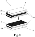
- the core 3 includes a plurality of spaced-apart flat hollow flow ducts 31, i.e. there is some free space between two adjacent flow ducts 31 and the coolant flows through these free spaces.
- the flow ducts are flow tubes, as represented in the figures. Flow ducts may be made of plates (not shown).
- the core 3 further includes a plurality of coolant turbulators 32 arranged between the flow ducts 31.
- one coolant turbulator 32 is situated between two adjacent flow ducts 31.
- the coolant turbulators 32 function to turn a laminar flow of the coolant into a turbulent one and, in turn, to increase the heat exchange efficiency.
- the coolant turbulators 32 can be omitted, if necessary.
- the flow ducts 31 are hollow and a medium to be cooled down, for example a fluid, such as a gas, flows there through.
- the flow ducts 31 have two wide sides, two narrow sides and two open ends.
- the flow ducts 31 are arranged with their wide sides parallel to each other.
- the flow ducts 31 can be provided internally with a series of air fins.
- the heat exchanger assembly 1 further comprises two headers 4.
- the headers 4 are located on and connected to two opposite ends of the core 3, i.e. the ones presenting the open ends of the flow ducts 31.
- each of the headers 4 is, on its entire perimeter, in fluid-tight contact with the housing 2.
- the header 4 comprises a plurality of through slots 42 so that the open ends of the flow ducts 31 fit into the slots 42.
- the number of the through slots 42 is equal to the number of the flow ducts 31 and the shape of the slots 42 corresponds to the shape of the cross-section of the open ends of the flow ducts 31.
- the heat exchanger assembly 1 comprises inlet and outlet conduits 5a, 5b for the medium to be cooled down.
- the inlet conduit 5a receives a hot medium from a motor vehicle and transfers it to the core 3 where it can be cooled down, whereas the outlet conduit 5b delivers a medium of a lower temperature to remaining parts of the motor vehicle.
- the inlet and outlet conduits 5a, 5b cover the headers 4 and close the housing 2.
- the inlet and outlet conduits 5a, 5b close two openings in the housing 2, which are intended for the flow of the medium to be cooled down, and make the housing 2 complete.
- the inlet and outlet conduits 5a, 5b are part of the housing 2 itself.
- a seal 6 may be placed between each of the headers 4 and each of the inlet and outlet conduits 5a, 5b.
- the headers 4 comprise a plurality of teeth 41, which are bended over protruding parts of the inlet and outlet conduits 5a, 5b in order to make the assembly even more rigid and resistant.
- All components of the heat exchanger assembly 1 mentioned above, except for the seal 6, can be made of materials suitable for brazing, for example aluminum, steel and their alloys. In order to obtain the proper fluid-tightness of the assembly all components thereof are connected to each other by brazing.
- the heat exchanger assembly 1 also comprises at least one filler 7 arranged between an inner wall of the housing 2 and at least one outermost flow duct 31a, 31b of the core 3.
- the heat exchanger assembly 1 comprises two fillers 7 - each filler 7 is arranged between the housing 2 and each of two outermost flow ducts 31a, 31b.
- Each filler 7 is in sealed contact with the inner wall of the housing 2 and the wide side of one of two outermost flow ducts 31a, 31b of the core 3.
- the fillers 7 fill a space between the housing 2 and the outermost flow ducts 31a, 31b of the core 3 and are strongly and tightly held between the inner wall of the housing 2 and the outermost flow ducts 31a, 31b of the core 3, i.e. there is no clearance between the housing 2, the fillers 7 and the outermost flow ducts 31, 31b.
- the fillers 7 cover at least 70%, preferably at least 80 % of the surface area of the wide sides of the outermost flow ducts, which they are in contact with and/or placed on.
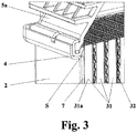
- the heat exchanger assembly 1 comprises a coolant channel or free space S between the header 4, the outermost flow duct 31a, 31b and the filler 7 and the coolant is able to flow through this free space S.
- the free space S can be present adjacent to each end of each filler 7 used. It in turn means that if two fillers 7 are employed there are four free spaces 7.
- the fillers 7 can be in the form of a plate.
- the plate can be solid. Nevertheless, the plate can also be provided with undercuts, openings or edges with special shapes, if desired.
- the fillers 7 can be made of a grid, a honeycomb structure or any other structured component.
- the fillers 7 are made of materials suitable for brazing, for example aluminum and its alloys. Therefore, the fillers 7 can be permanently connected to the housing 2 and the wide sides of the outermost flow ducts 31a, 31b by brazing.
- another methods of connection can be employed.
- the fillers 7 can be glued to the surrounding components of the heat exchanger assembly 1 or even the fillers 7 can be simply held tightly between the housing and the outermost flow ducts 31a, 31b, as stated above, so that any relative movement between these parts is prevented and the housing 2, the fillers 7 and the outermost flow ducts 31a, 31b are tightly associated with each other.
- the fillers 7 can be made of materials other than those suitable for brazing, for example plastic materials.
- the fillers 7 can be made by any suitable manufacturing process, e.g. stamping, machining, casting or injection. As stated above, the appropriate materials for the fillers 7 include a full range of materials, such as aluminum, steel, their alloys, ferric materials, composites or plastics materials.
- the fillers 7 rigidly connect the outermost flow ducts 31a, 31b to the housing 2 to equalize the stress level between the outermost flow ducts 31a, 31b and the housing 2.
- the aim to prevent a differential thermal expansion between the housing 2 and the outermost flow ducts 31a, 31b is achieved by the fillers 7 of the present invention.
Landscapes
- Engineering & Computer Science (AREA)
- Physics & Mathematics (AREA)
- Thermal Sciences (AREA)
- Mechanical Engineering (AREA)
- General Engineering & Computer Science (AREA)
- Chemical & Material Sciences (AREA)
- Combustion & Propulsion (AREA)
- Heat-Exchange Devices With Radiators And Conduit Assemblies (AREA)
Abstract
Description
- The present invention relates to a heat exchanger assembly, especially a water charge air cooler for a motor vehicle.
- A general structure of heat exchanger assemblies is known from the prior art. The prior art heat exchanger assembly comprises: a housing; a core situated in the housing and comprising a plurality of spaced-apart flow ducts, which in turn include two outermost flow ducts; two headers placed on the core at open ends of the flow ducts; and inlet and outlet conduits covering the headers and closing the housing. A through passage/space for the flow of a coolant exists between the housing and the outermost flow ducts. Moreover, a series of coolant turbulators can be provided between the flow ducts. Two additional coolant turbulators can be arranged between an inner wall of the housing and each of the outermost flow ducts, however these turbulators do not obstruct the flow of the coolant as there is always some passage for the coolant between inlet and outlet ports of the housing. All components of the assembly are connected to each other by brazing. In particular, the flow ducts are connected at their open ends to the headers.
- In the prior art solution described above, when the temperature is changed, the outermost flow ducts expand in a different way compared to the housing. Both the flow ducts and the housing are connected to the headers and the outermost flow ducts are supported by the headers only at their ends. In this way the outermost flow ducts are subjected to high stresses. These stresses lead to cracking of the outermost flow ducts close to the junction between the header and the outermost flow ducts after a number of working cycles. This in turn results in undesired mixing of the coolant and a gas to be cooled down within the assembly.
- The aim of the present invention is to eliminate the drawbacks of the prior art solutions described above, especially by increasing the fatigue strength of the heat exchanger assembly. This aim is achieved by a heat exchanger assembly as defined in the independent claim.
- A heat exchanger assembly according to the present invention comprises: a housing and a core situated inside the housing, the core comprising a plurality of flow ducts, the flow ducts each comprising two wide sides, the flow ducts including two outermost flow ducts. The heat exchanger assembly further comprises at least one filler. The at least one filler is placed between and is in sealed contact with the housing and the wide side of at least one outermost flow duct so that the at least one filler covers at least 70% of the wide side of the at least one outermost flow duct, which is in contact with the at least one filler. The at least one filler is able to prevent a coolant from flowing in a space defined between the housing and the at least one outermost flow duct and filled with the at least one filler.
- The at least one filler contacts both the housing and the at least one outermost flow duct and is tightly held between them and, therefore, there is a limited passage for the coolant, from the inlet port to the outlet port of the housing. The at least one filler has to cover the surface area of the wide side of the at least one outermost duct as much as possible. In particular, the at least one filler covers at least 70%, preferably at least 80% of the wide side of the at least one outermost flow duct on which the at least one filler is placed.
- The at least one outermost flow duct is tightly associated by the at least one filler with an inner wall of the housing, what reduces the thermal expansion of the at least one outermost flow duct. This in turn reduces stresses at the junction between the headers and the at least one outermost flow duct and equalizes stresses in the housing and the at least one outermost flow duct. Hence, the fatigue strength of the at least one outermost flow duct, under the influence of violent changes of temperature, is increased. The risk of cracking at the junction between the header and the at least one outermost flow duct is greatly reduced and the heat exchanger assembly of the present invention can work for a bigger number of working cycles. The at least one filler is connected permanently to the housing and the at least one outermost flow duct, whereby the fatigue strength of the at least one flow duct can be increased even more.
- The present invention is presented, in a non-limiting example thereof, in the drawings, wherein:
-
Fig. 1 shows a perspective exploded view of a heat exchanger assembly of the present invention, -
Fig. 2 shows a perspective exploded view of a core used in the heat exchanger assembly of the present invention, and -
Fig. 3 shows a partial cut-away view of a detail of the heat exchanger assembly of the present invention. - A heat exchanger assembly according to the present invention is indicated as a whole by numeral reference 1. The heat exchanger assembly 1 comprises a
housing 2, which in the embodiment shown in the figures is made of two separate half-shells, i.e. a first half-shell 21 and a second half-shell 22. Of course, thehousing 2 can consist of any appropriate number of shells and/or plates, e.g. three, four, etc. Thehousing 2 includes inlet andoutlet ports degassing port 25, which serves to remove the air that may be trapped in the coolant. - A
core 3 is placed inside thehousing 2. Thecore 3 includes a plurality of spaced-apart flathollow flow ducts 31, i.e. there is some free space between twoadjacent flow ducts 31 and the coolant flows through these free spaces. In the preferred embodiment of the present invention, the flow ducts are flow tubes, as represented in the figures. Flow ducts may be made of plates (not shown). - In the preferred embodiment of the invention, shown in the figures, especially in
figure 3 , thecore 3 further includes a plurality ofcoolant turbulators 32 arranged between theflow ducts 31. Namely, onecoolant turbulator 32 is situated between twoadjacent flow ducts 31. Thecoolant turbulators 32 function to turn a laminar flow of the coolant into a turbulent one and, in turn, to increase the heat exchange efficiency. Of course, in other embodiments of the invention, thecoolant turbulators 32 can be omitted, if necessary. - The
flow ducts 31 are hollow and a medium to be cooled down, for example a fluid, such as a gas, flows there through. Theflow ducts 31 have two wide sides, two narrow sides and two open ends. Theflow ducts 31 are arranged with their wide sides parallel to each other. Theflow ducts 31 can be provided internally with a series of air fins. - The heat exchanger assembly 1 further comprises two
headers 4. Theheaders 4 are located on and connected to two opposite ends of thecore 3, i.e. the ones presenting the open ends of theflow ducts 31. Moreover, each of theheaders 4 is, on its entire perimeter, in fluid-tight contact with thehousing 2. Theheader 4 comprises a plurality of throughslots 42 so that the open ends of theflow ducts 31 fit into theslots 42. The number of thethrough slots 42 is equal to the number of theflow ducts 31 and the shape of theslots 42 corresponds to the shape of the cross-section of the open ends of theflow ducts 31. - Moreover, the heat exchanger assembly 1 comprises inlet and
outlet conduits inlet conduit 5a receives a hot medium from a motor vehicle and transfers it to thecore 3 where it can be cooled down, whereas theoutlet conduit 5b delivers a medium of a lower temperature to remaining parts of the motor vehicle. The inlet and outlet conduits 5a, 5b cover theheaders 4 and close thehousing 2. In other words, the inlet and outlet conduits 5a, 5b close two openings in thehousing 2, which are intended for the flow of the medium to be cooled down, and make thehousing 2 complete. In fact, the inlet andoutlet conduits housing 2 itself. Aseal 6 may be placed between each of theheaders 4 and each of the inlet andoutlet conduits headers 4 comprise a plurality ofteeth 41, which are bended over protruding parts of the inlet andoutlet conduits - All components of the heat exchanger assembly 1 mentioned above, except for the
seal 6, can be made of materials suitable for brazing, for example aluminum, steel and their alloys. In order to obtain the proper fluid-tightness of the assembly all components thereof are connected to each other by brazing. - The heat exchanger assembly 1 also comprises at least one
filler 7 arranged between an inner wall of thehousing 2 and at least oneoutermost flow duct core 3. In a preferred embodiment of the invention the heat exchanger assembly 1 comprises two fillers 7 - eachfiller 7 is arranged between thehousing 2 and each of twooutermost flow ducts filler 7 is in sealed contact with the inner wall of thehousing 2 and the wide side of one of twooutermost flow ducts core 3. In other words, thefillers 7 fill a space between thehousing 2 and theoutermost flow ducts core 3 and are strongly and tightly held between the inner wall of thehousing 2 and theoutermost flow ducts core 3, i.e. there is no clearance between thehousing 2, thefillers 7 and theoutermost flow ducts - The
fillers 7 cover at least 70%, preferably at least 80 % of the surface area of the wide sides of the outermost flow ducts, which they are in contact with and/or placed on. - Additionally, if the
fillers 7 do not cover the whole surface area of theoutermost flow ducts header 4, theoutermost flow duct filler 7 and the coolant is able to flow through this free space S. The free space S can be present adjacent to each end of eachfiller 7 used. It in turn means that if twofillers 7 are employed there are fourfree spaces 7. - In one preferred embodiment of the present invention the
fillers 7 can be in the form of a plate. The plate can be solid. Nevertheless, the plate can also be provided with undercuts, openings or edges with special shapes, if desired. - In other embodiments of the present invention the
fillers 7 can be made of a grid, a honeycomb structure or any other structured component. In any case it should be noted that it is important to orientate thefillers 7 within the heat exchanger assembly 1 in such a way that the flow of the coolant from theinlet port 24 to theoutlet port 25 of thehousing 2 and through a space defined between thehousing 2 and theoutermost flow ducts fillers 7, is prevented and thefillers 7 are tightly held between surrounding components of the assembly. In other words, the coolant cannot flow through thefillers 7 themselves. - Preferably, the
fillers 7 are made of materials suitable for brazing, for example aluminum and its alloys. Therefore, thefillers 7 can be permanently connected to thehousing 2 and the wide sides of theoutermost flow ducts fillers 7 can be glued to the surrounding components of the heat exchanger assembly 1 or even thefillers 7 can be simply held tightly between the housing and theoutermost flow ducts housing 2, thefillers 7 and theoutermost flow ducts fillers 7 can be made of materials other than those suitable for brazing, for example plastic materials. - The
fillers 7 can be made by any suitable manufacturing process, e.g. stamping, machining, casting or injection. As stated above, the appropriate materials for thefillers 7 include a full range of materials, such as aluminum, steel, their alloys, ferric materials, composites or plastics materials. - The
fillers 7 rigidly connect theoutermost flow ducts housing 2 to equalize the stress level between theoutermost flow ducts housing 2. - When assembling the heat exchanger assembly 1 of the present invention minimal gaps between the
fillers 7 and thehousing 2 and/or theoutermost flow ducts fillers 7 with surrounding components. Therefore, these gaps may result in limited passages for the coolant. - The aim to prevent a differential thermal expansion between the
housing 2 and theoutermost flow ducts fillers 7 of the present invention.
Claims (15)
- A heat exchanger assembly (1), comprising:a housing (2); anda core (3) situated inside said housing (2), said core (3) comprising a plurality of flow ducts (31), said flow ducts (31) each comprising two wide sides, said flow ducts (31) including two outermost flow ducts (31a, 31b);characterized in that it further comprises at least one filler (7) placed between and being in sealed contact with said housing (2) and said wide side of at least one outermost flow duct (31a, 31b) so that said at least one filler (7) covers at least 70% of said wide side of said at least one outermost flow duct (31a, 31b), which is in contact with said at least one filler (7), said at least one filler (7) being able to prevent a coolant from flowing in a space defined between said housing (2) and said at least one outermost flow duct (31a, 31b) and filled with said at least one filler (7).
- The heat exchanger assembly (1) according to claim 1, characterized in that said at least one filler (7) is chosen from the group including a solid plate, a grid and a honeycomb structure.
- The heat exchanger assembly (1) according to any one of the preceding claims, characterized in that said at least one filler (7) is held tightly between said housing (2) and said at least one outermost flow duct (31a, 31b).
- The heat exchanger assembly (1) according to any one of the preceding claims, characterized in that said at least one filler (7) is made of one or more plastic materials.
- The heat exchanger assembly (1) according to any one of claims 1 to 3, characterized in that said at least one filler (7) is made of one or more materials suitable for brazing.
- The heat exchanger assembly (1) according to any one of claims 1 or 2 or 3 or 5, characterized in that said at least one filler (7) is made of aluminum.
- The heat exchanger assembly (1) according to any one of the preceding claims, characterized in that said at least one filler (7) is connected to said housing (2) and said at least one outermost flow duct (31a, 31b) by gluing.
- The heat exchanger assembly (1) according to any one of claims 5 or 6, characterized in that said at least one filler (7) is connected to said housing (2) and said at least one outermost flow duct (31a, 31b) by brazing.
- The heat exchanger assembly (1) according to any one of the preceding claims, characterized in that said core (3) further comprises a plurality of coolant turbulators (32), each coolant turbulator (32) being arranged between two adjacent flow ducts (31).
- The heat exchanger assembly (1) according to any one of the preceding claims, characterized in that said flow ducts are flow tubes and that said heat exchanger assembly (1) further comprises two headers (4) having a plurality of slots (42), the number of which is equal to the number of said flow ducts (31) of said core (3), the shape of said slots (42) corresponding to the shape of the cross-section of said flow ducts (31).
- The heat exchanger assembly (1) according to any one of the preceding claims, characterized in that it further comprises inlet and outlet conduits (5a, 5b) and two headers (4) placed on opposite ends of said core (3) and comprising a plurality of teeth (41), which are bent over said inlet and outlet conduits (5a, 5b).
- The heat exchanger assembly (1) according to any one of the preceding claims, characterized in that it further comprises a free space (S) defined between said headers (4), said at least one outermost flow duct (31a, 31b) and said at least one filler (7) through which a coolant is able to flow.
- The heat exchanger assembly (1) according to any one of the preceding claims, characterized in that said at least one filler (7) covers at least 80% of said wide side of said at least one outermost flow duct (31a, 31b).
- The heat exchanger assembly (1) according to any one of the preceding claims, characterized in that it comprises two fillers (7), said fillers (7) each being placed between and being in sealed contact with said housing (2) and said wide side of one of two outermost flow ducts (31a, 31b).
- The heat exchanger assembly (1) according to any one of the preceding claims, characterized in that said heat exchanger assembly (1) is a water charge air cooler.
Priority Applications (1)
| Application Number | Priority Date | Filing Date | Title |
|---|---|---|---|
| EP17461512.0A EP3376147B1 (en) | 2017-03-15 | 2017-03-15 | Heat exchanger assembly |
Applications Claiming Priority (1)
| Application Number | Priority Date | Filing Date | Title |
|---|---|---|---|
| EP17461512.0A EP3376147B1 (en) | 2017-03-15 | 2017-03-15 | Heat exchanger assembly |
Publications (2)
| Publication Number | Publication Date |
|---|---|
| EP3376147A1 true EP3376147A1 (en) | 2018-09-19 |
| EP3376147B1 EP3376147B1 (en) | 2021-01-27 |
Family
ID=58360950
Family Applications (1)
| Application Number | Title | Priority Date | Filing Date |
|---|---|---|---|
| EP17461512.0A Active EP3376147B1 (en) | 2017-03-15 | 2017-03-15 | Heat exchanger assembly |
Country Status (1)
| Country | Link |
|---|---|
| EP (1) | EP3376147B1 (en) |
Citations (5)
| Publication number | Priority date | Publication date | Assignee | Title |
|---|---|---|---|---|
| DE2903543A1 (en) * | 1979-01-31 | 1980-08-07 | Daimler Benz Ag | Water cooled vehicle oil cooler - has end water entries and bottom oil entries with tube bundle units between |
| DE4313505A1 (en) * | 1993-04-24 | 1994-10-27 | Knecht Filterwerke Gmbh | Liquid cooler (fluid cooler, chiller) of plate-type design |
| US20110168370A1 (en) * | 2008-06-26 | 2011-07-14 | Paul Garret | Heat exchanger and casing for the heat exchanger |
| WO2011126449A1 (en) * | 2010-04-08 | 2011-10-13 | Titanx Engine Cooling Holding Ab | Heat exchanger with bypass stopper, oil cooling system and method for cooling oil |
| US20140299295A1 (en) * | 2013-04-04 | 2014-10-09 | Modine Manufacturing Company | Heat exchanger and production method |
-
2017
- 2017-03-15 EP EP17461512.0A patent/EP3376147B1/en active Active
Patent Citations (5)
| Publication number | Priority date | Publication date | Assignee | Title |
|---|---|---|---|---|
| DE2903543A1 (en) * | 1979-01-31 | 1980-08-07 | Daimler Benz Ag | Water cooled vehicle oil cooler - has end water entries and bottom oil entries with tube bundle units between |
| DE4313505A1 (en) * | 1993-04-24 | 1994-10-27 | Knecht Filterwerke Gmbh | Liquid cooler (fluid cooler, chiller) of plate-type design |
| US20110168370A1 (en) * | 2008-06-26 | 2011-07-14 | Paul Garret | Heat exchanger and casing for the heat exchanger |
| WO2011126449A1 (en) * | 2010-04-08 | 2011-10-13 | Titanx Engine Cooling Holding Ab | Heat exchanger with bypass stopper, oil cooling system and method for cooling oil |
| US20140299295A1 (en) * | 2013-04-04 | 2014-10-09 | Modine Manufacturing Company | Heat exchanger and production method |
Also Published As
| Publication number | Publication date |
|---|---|
| EP3376147B1 (en) | 2021-01-27 |
Similar Documents
| Publication | Publication Date | Title |
|---|---|---|
| US10845126B2 (en) | Counterflow helical heat exchanger | |
| US11274884B2 (en) | Heat exchanger module with an adapter module for direct mounting to a vehicle component | |
| JP4775287B2 (en) | Heat exchanger | |
| JP6291474B2 (en) | Heat exchanger | |
| JP4880094B2 (en) | Heat exchanger | |
| KR19990022246A (en) | heat transmitter | |
| JP2015534030A (en) | Heat exchanger | |
| US6470963B2 (en) | Heat exchanger | |
| EP3561426B1 (en) | Heat exchange device | |
| CN109141083B (en) | Primary surface heat exchanger applied to fuel cell | |
| JPWO2016190445A1 (en) | Heat exchanger tank structure and manufacturing method thereof | |
| US20090242182A1 (en) | Heat Exchanger Plate | |
| US10281217B2 (en) | Multifluid heat exchanger | |
| EP2265882B1 (en) | Header plate and heat exchanger comprising same | |
| WO2025200734A1 (en) | Coil heat exchanger and heating, ventilation, and air conditioning device | |
| JP7173629B2 (en) | Tank and multi-channel liquid cooling radiator using the same | |
| JP2020516846A (en) | Heat exchanger for motor vehicles | |
| JP4607626B2 (en) | Efficient heat exchanger and engine using the same | |
| JP2010121925A (en) | Heat exchanger | |
| EP3396296B1 (en) | Heat exchanger assembly | |
| WO2019174734A1 (en) | Heat exchanger assembly | |
| EP3376147B1 (en) | Heat exchanger assembly | |
| US20130062039A1 (en) | System and method for exchanging heat | |
| US9310135B1 (en) | Configureable heat exchanger | |
| EP3457068B1 (en) | Heat exchanger assembly |
Legal Events
| Date | Code | Title | Description |
|---|---|---|---|
| PUAI | Public reference made under article 153(3) epc to a published international application that has entered the european phase |
Free format text: ORIGINAL CODE: 0009012 |
|
| STAA | Information on the status of an ep patent application or granted ep patent |
Free format text: STATUS: THE APPLICATION HAS BEEN PUBLISHED |
|
| AK | Designated contracting states |
Kind code of ref document: A1 Designated state(s): AL AT BE BG CH CY CZ DE DK EE ES FI FR GB GR HR HU IE IS IT LI LT LU LV MC MK MT NL NO PL PT RO RS SE SI SK SM TR |
|
| AX | Request for extension of the european patent |
Extension state: BA ME |
|
| STAA | Information on the status of an ep patent application or granted ep patent |
Free format text: STATUS: REQUEST FOR EXAMINATION WAS MADE |
|
| 17P | Request for examination filed |
Effective date: 20190419 |
|
| RBV | Designated contracting states (corrected) |
Designated state(s): AL AT BE BG CH CY CZ DE DK EE ES FI FR GB GR HR HU IE IS IT LI LT LU LV MC MK MT NL NO PL PT RO RS SE SI SK SM TR |
|
| GRAP | Despatch of communication of intention to grant a patent |
Free format text: ORIGINAL CODE: EPIDOSNIGR1 |
|
| RIC1 | Information provided on ipc code assigned before grant |
Ipc: F02B 29/04 20060101ALI20200131BHEP Ipc: F28D 9/00 20060101AFI20200131BHEP Ipc: F28F 9/00 20060101ALI20200131BHEP Ipc: F28D 21/00 20060101ALI20200131BHEP |
|
| STAA | Information on the status of an ep patent application or granted ep patent |
Free format text: STATUS: GRANT OF PATENT IS INTENDED |
|
| INTG | Intention to grant announced |
Effective date: 20200312 |
|
| GRAS | Grant fee paid |
Free format text: ORIGINAL CODE: EPIDOSNIGR3 |
|
| GRAA | (expected) grant |
Free format text: ORIGINAL CODE: 0009210 |
|
| STAA | Information on the status of an ep patent application or granted ep patent |
Free format text: STATUS: THE PATENT HAS BEEN GRANTED |
|
| AK | Designated contracting states |
Kind code of ref document: B1 Designated state(s): AL AT BE BG CH CY CZ DE DK EE ES FI FR GB GR HR HU IE IS IT LI LT LU LV MC MK MT NL NO PL PT RO RS SE SI SK SM TR |
|
| REG | Reference to a national code |
Ref country code: GB Ref legal event code: FG4D |
|
| REG | Reference to a national code |
Ref country code: CH Ref legal event code: EP |
|
| REG | Reference to a national code |
Ref country code: AT Ref legal event code: REF Ref document number: 1358736 Country of ref document: AT Kind code of ref document: T Effective date: 20210215 |
|
| REG | Reference to a national code |
Ref country code: IE Ref legal event code: FG4D |
|
| REG | Reference to a national code |
Ref country code: DE Ref legal event code: R096 Ref document number: 602017032025 Country of ref document: DE |
|
| REG | Reference to a national code |
Ref country code: NL Ref legal event code: MP Effective date: 20210127 |
|
| REG | Reference to a national code |
Ref country code: LT Ref legal event code: MG9D |
|
| REG | Reference to a national code |
Ref country code: AT Ref legal event code: MK05 Ref document number: 1358736 Country of ref document: AT Kind code of ref document: T Effective date: 20210127 |
|
| PG25 | Lapsed in a contracting state [announced via postgrant information from national office to epo] |
Ref country code: BG Free format text: LAPSE BECAUSE OF FAILURE TO SUBMIT A TRANSLATION OF THE DESCRIPTION OR TO PAY THE FEE WITHIN THE PRESCRIBED TIME-LIMIT Effective date: 20210427 Ref country code: LT Free format text: LAPSE BECAUSE OF FAILURE TO SUBMIT A TRANSLATION OF THE DESCRIPTION OR TO PAY THE FEE WITHIN THE PRESCRIBED TIME-LIMIT Effective date: 20210127 Ref country code: FI Free format text: LAPSE BECAUSE OF FAILURE TO SUBMIT A TRANSLATION OF THE DESCRIPTION OR TO PAY THE FEE WITHIN THE PRESCRIBED TIME-LIMIT Effective date: 20210127 Ref country code: HR Free format text: LAPSE BECAUSE OF FAILURE TO SUBMIT A TRANSLATION OF THE DESCRIPTION OR TO PAY THE FEE WITHIN THE PRESCRIBED TIME-LIMIT Effective date: 20210127 Ref country code: GR Free format text: LAPSE BECAUSE OF FAILURE TO SUBMIT A TRANSLATION OF THE DESCRIPTION OR TO PAY THE FEE WITHIN THE PRESCRIBED TIME-LIMIT Effective date: 20210428 Ref country code: NO Free format text: LAPSE BECAUSE OF FAILURE TO SUBMIT A TRANSLATION OF THE DESCRIPTION OR TO PAY THE FEE WITHIN THE PRESCRIBED TIME-LIMIT Effective date: 20210427 Ref country code: PT Free format text: LAPSE BECAUSE OF FAILURE TO SUBMIT A TRANSLATION OF THE DESCRIPTION OR TO PAY THE FEE WITHIN THE PRESCRIBED TIME-LIMIT Effective date: 20210527 |
|
| PG25 | Lapsed in a contracting state [announced via postgrant information from national office to epo] |
Ref country code: AT Free format text: LAPSE BECAUSE OF FAILURE TO SUBMIT A TRANSLATION OF THE DESCRIPTION OR TO PAY THE FEE WITHIN THE PRESCRIBED TIME-LIMIT Effective date: 20210127 Ref country code: LV Free format text: LAPSE BECAUSE OF FAILURE TO SUBMIT A TRANSLATION OF THE DESCRIPTION OR TO PAY THE FEE WITHIN THE PRESCRIBED TIME-LIMIT Effective date: 20210127 Ref country code: RS Free format text: LAPSE BECAUSE OF FAILURE TO SUBMIT A TRANSLATION OF THE DESCRIPTION OR TO PAY THE FEE WITHIN THE PRESCRIBED TIME-LIMIT Effective date: 20210127 Ref country code: PL Free format text: LAPSE BECAUSE OF FAILURE TO SUBMIT A TRANSLATION OF THE DESCRIPTION OR TO PAY THE FEE WITHIN THE PRESCRIBED TIME-LIMIT Effective date: 20210127 Ref country code: SE Free format text: LAPSE BECAUSE OF FAILURE TO SUBMIT A TRANSLATION OF THE DESCRIPTION OR TO PAY THE FEE WITHIN THE PRESCRIBED TIME-LIMIT Effective date: 20210127 |
|
| PG25 | Lapsed in a contracting state [announced via postgrant information from national office to epo] |
Ref country code: IS Free format text: LAPSE BECAUSE OF FAILURE TO SUBMIT A TRANSLATION OF THE DESCRIPTION OR TO PAY THE FEE WITHIN THE PRESCRIBED TIME-LIMIT Effective date: 20210527 |
|
| REG | Reference to a national code |
Ref country code: DE Ref legal event code: R097 Ref document number: 602017032025 Country of ref document: DE |
|
| PG25 | Lapsed in a contracting state [announced via postgrant information from national office to epo] |
Ref country code: CZ Free format text: LAPSE BECAUSE OF FAILURE TO SUBMIT A TRANSLATION OF THE DESCRIPTION OR TO PAY THE FEE WITHIN THE PRESCRIBED TIME-LIMIT Effective date: 20210127 Ref country code: EE Free format text: LAPSE BECAUSE OF FAILURE TO SUBMIT A TRANSLATION OF THE DESCRIPTION OR TO PAY THE FEE WITHIN THE PRESCRIBED TIME-LIMIT Effective date: 20210127 Ref country code: MC Free format text: LAPSE BECAUSE OF FAILURE TO SUBMIT A TRANSLATION OF THE DESCRIPTION OR TO PAY THE FEE WITHIN THE PRESCRIBED TIME-LIMIT Effective date: 20210127 Ref country code: SM Free format text: LAPSE BECAUSE OF FAILURE TO SUBMIT A TRANSLATION OF THE DESCRIPTION OR TO PAY THE FEE WITHIN THE PRESCRIBED TIME-LIMIT Effective date: 20210127 |
|
| REG | Reference to a national code |
Ref country code: CH Ref legal event code: PL |
|
| PG25 | Lapsed in a contracting state [announced via postgrant information from national office to epo] |
Ref country code: RO Free format text: LAPSE BECAUSE OF FAILURE TO SUBMIT A TRANSLATION OF THE DESCRIPTION OR TO PAY THE FEE WITHIN THE PRESCRIBED TIME-LIMIT Effective date: 20210127 Ref country code: SK Free format text: LAPSE BECAUSE OF FAILURE TO SUBMIT A TRANSLATION OF THE DESCRIPTION OR TO PAY THE FEE WITHIN THE PRESCRIBED TIME-LIMIT Effective date: 20210127 Ref country code: DK Free format text: LAPSE BECAUSE OF FAILURE TO SUBMIT A TRANSLATION OF THE DESCRIPTION OR TO PAY THE FEE WITHIN THE PRESCRIBED TIME-LIMIT Effective date: 20210127 |
|
| PLBE | No opposition filed within time limit |
Free format text: ORIGINAL CODE: 0009261 |
|
| STAA | Information on the status of an ep patent application or granted ep patent |
Free format text: STATUS: NO OPPOSITION FILED WITHIN TIME LIMIT |
|
| REG | Reference to a national code |
Ref country code: BE Ref legal event code: MM Effective date: 20210331 |
|
| GBPC | Gb: european patent ceased through non-payment of renewal fee |
Effective date: 20210427 |
|
| 26N | No opposition filed |
Effective date: 20211028 |
|
| PG25 | Lapsed in a contracting state [announced via postgrant information from national office to epo] |
Ref country code: ES Free format text: LAPSE BECAUSE OF FAILURE TO SUBMIT A TRANSLATION OF THE DESCRIPTION OR TO PAY THE FEE WITHIN THE PRESCRIBED TIME-LIMIT Effective date: 20210127 Ref country code: AL Free format text: LAPSE BECAUSE OF FAILURE TO SUBMIT A TRANSLATION OF THE DESCRIPTION OR TO PAY THE FEE WITHIN THE PRESCRIBED TIME-LIMIT Effective date: 20210127 Ref country code: CH Free format text: LAPSE BECAUSE OF NON-PAYMENT OF DUE FEES Effective date: 20210331 Ref country code: LI Free format text: LAPSE BECAUSE OF NON-PAYMENT OF DUE FEES Effective date: 20210331 Ref country code: LU Free format text: LAPSE BECAUSE OF NON-PAYMENT OF DUE FEES Effective date: 20210315 Ref country code: IE Free format text: LAPSE BECAUSE OF NON-PAYMENT OF DUE FEES Effective date: 20210315 Ref country code: GB Free format text: LAPSE BECAUSE OF NON-PAYMENT OF DUE FEES Effective date: 20210427 |
|
| PG25 | Lapsed in a contracting state [announced via postgrant information from national office to epo] |
Ref country code: SI Free format text: LAPSE BECAUSE OF FAILURE TO SUBMIT A TRANSLATION OF THE DESCRIPTION OR TO PAY THE FEE WITHIN THE PRESCRIBED TIME-LIMIT Effective date: 20210127 |
|
| PG25 | Lapsed in a contracting state [announced via postgrant information from national office to epo] |
Ref country code: IT Free format text: LAPSE BECAUSE OF FAILURE TO SUBMIT A TRANSLATION OF THE DESCRIPTION OR TO PAY THE FEE WITHIN THE PRESCRIBED TIME-LIMIT Effective date: 20210127 |
|
| PG25 | Lapsed in a contracting state [announced via postgrant information from national office to epo] |
Ref country code: IS Free format text: LAPSE BECAUSE OF FAILURE TO SUBMIT A TRANSLATION OF THE DESCRIPTION OR TO PAY THE FEE WITHIN THE PRESCRIBED TIME-LIMIT Effective date: 20210527 |
|
| PG25 | Lapsed in a contracting state [announced via postgrant information from national office to epo] |
Ref country code: BE Free format text: LAPSE BECAUSE OF NON-PAYMENT OF DUE FEES Effective date: 20210331 |
|
| PG25 | Lapsed in a contracting state [announced via postgrant information from national office to epo] |
Ref country code: NL Free format text: LAPSE BECAUSE OF NON-PAYMENT OF DUE FEES Effective date: 20210127 Ref country code: CY Free format text: LAPSE BECAUSE OF FAILURE TO SUBMIT A TRANSLATION OF THE DESCRIPTION OR TO PAY THE FEE WITHIN THE PRESCRIBED TIME-LIMIT Effective date: 20210127 |
|
| P01 | Opt-out of the competence of the unified patent court (upc) registered |
Effective date: 20230528 |
|
| PG25 | Lapsed in a contracting state [announced via postgrant information from national office to epo] |
Ref country code: HU Free format text: LAPSE BECAUSE OF FAILURE TO SUBMIT A TRANSLATION OF THE DESCRIPTION OR TO PAY THE FEE WITHIN THE PRESCRIBED TIME-LIMIT; INVALID AB INITIO Effective date: 20170315 |
|
| PG25 | Lapsed in a contracting state [announced via postgrant information from national office to epo] |
Ref country code: MK Free format text: LAPSE BECAUSE OF FAILURE TO SUBMIT A TRANSLATION OF THE DESCRIPTION OR TO PAY THE FEE WITHIN THE PRESCRIBED TIME-LIMIT Effective date: 20210127 |
|
| PG25 | Lapsed in a contracting state [announced via postgrant information from national office to epo] |
Ref country code: MT Free format text: LAPSE BECAUSE OF FAILURE TO SUBMIT A TRANSLATION OF THE DESCRIPTION OR TO PAY THE FEE WITHIN THE PRESCRIBED TIME-LIMIT Effective date: 20210127 |
|
| PGFP | Annual fee paid to national office [announced via postgrant information from national office to epo] |
Ref country code: FR Payment date: 20250331 Year of fee payment: 9 |
|
| PG25 | Lapsed in a contracting state [announced via postgrant information from national office to epo] |
Ref country code: TR Free format text: LAPSE BECAUSE OF FAILURE TO SUBMIT A TRANSLATION OF THE DESCRIPTION OR TO PAY THE FEE WITHIN THE PRESCRIBED TIME-LIMIT Effective date: 20210127 |
|
| PGFP | Annual fee paid to national office [announced via postgrant information from national office to epo] |
Ref country code: DE Payment date: 20260313 Year of fee payment: 10 |