EP3376125A1 - Outdoor unit of air conditioner - Google Patents
Outdoor unit of air conditioner Download PDFInfo
- Publication number
- EP3376125A1 EP3376125A1 EP18156790.0A EP18156790A EP3376125A1 EP 3376125 A1 EP3376125 A1 EP 3376125A1 EP 18156790 A EP18156790 A EP 18156790A EP 3376125 A1 EP3376125 A1 EP 3376125A1
- Authority
- EP
- European Patent Office
- Prior art keywords
- outdoor unit
- raised portions
- bell mouth
- fan
- height
- Prior art date
- Legal status (The legal status is an assumption and is not a legal conclusion. Google has not performed a legal analysis and makes no representation as to the accuracy of the status listed.)
- Granted
Links
Images




Classifications
-
- F—MECHANICAL ENGINEERING; LIGHTING; HEATING; WEAPONS; BLASTING
- F24—HEATING; RANGES; VENTILATING
- F24F—AIR-CONDITIONING; AIR-HUMIDIFICATION; VENTILATION; USE OF AIR CURRENTS FOR SCREENING
- F24F1/00—Room units for air-conditioning, e.g. separate or self-contained units or units receiving primary air from a central station
- F24F1/06—Separate outdoor units, e.g. outdoor unit to be linked to a separate room comprising a compressor and a heat exchanger
-
- F—MECHANICAL ENGINEERING; LIGHTING; HEATING; WEAPONS; BLASTING
- F24—HEATING; RANGES; VENTILATING
- F24F—AIR-CONDITIONING; AIR-HUMIDIFICATION; VENTILATION; USE OF AIR CURRENTS FOR SCREENING
- F24F1/00—Room units for air-conditioning, e.g. separate or self-contained units or units receiving primary air from a central station
- F24F1/06—Separate outdoor units, e.g. outdoor unit to be linked to a separate room comprising a compressor and a heat exchanger
- F24F1/38—Fan details of outdoor units, e.g. bell-mouth shaped inlets or fan mountings
-
- F—MECHANICAL ENGINEERING; LIGHTING; HEATING; WEAPONS; BLASTING
- F24—HEATING; RANGES; VENTILATING
- F24F—AIR-CONDITIONING; AIR-HUMIDIFICATION; VENTILATION; USE OF AIR CURRENTS FOR SCREENING
- F24F1/00—Room units for air-conditioning, e.g. separate or self-contained units or units receiving primary air from a central station
- F24F1/06—Separate outdoor units, e.g. outdoor unit to be linked to a separate room comprising a compressor and a heat exchanger
- F24F1/14—Heat exchangers specially adapted for separate outdoor units
- F24F1/16—Arrangement or mounting thereof
-
- F—MECHANICAL ENGINEERING; LIGHTING; HEATING; WEAPONS; BLASTING
- F24—HEATING; RANGES; VENTILATING
- F24F—AIR-CONDITIONING; AIR-HUMIDIFICATION; VENTILATION; USE OF AIR CURRENTS FOR SCREENING
- F24F1/00—Room units for air-conditioning, e.g. separate or self-contained units or units receiving primary air from a central station
- F24F1/06—Separate outdoor units, e.g. outdoor unit to be linked to a separate room comprising a compressor and a heat exchanger
- F24F1/46—Component arrangements in separate outdoor units
-
- F—MECHANICAL ENGINEERING; LIGHTING; HEATING; WEAPONS; BLASTING
- F24—HEATING; RANGES; VENTILATING
- F24F—AIR-CONDITIONING; AIR-HUMIDIFICATION; VENTILATION; USE OF AIR CURRENTS FOR SCREENING
- F24F1/00—Room units for air-conditioning, e.g. separate or self-contained units or units receiving primary air from a central station
- F24F1/06—Separate outdoor units, e.g. outdoor unit to be linked to a separate room comprising a compressor and a heat exchanger
- F24F1/56—Casing or covers of separate outdoor units, e.g. fan guards
-
- F—MECHANICAL ENGINEERING; LIGHTING; HEATING; WEAPONS; BLASTING
- F24—HEATING; RANGES; VENTILATING
- F24F—AIR-CONDITIONING; AIR-HUMIDIFICATION; VENTILATION; USE OF AIR CURRENTS FOR SCREENING
- F24F13/00—Details common to, or for air-conditioning, air-humidification, ventilation or use of air currents for screening
- F24F13/08—Air-flow control members, e.g. louvres, grilles, flaps or guide plates
- F24F13/082—Grilles, registers or guards
- F24F13/084—Grilles, registers or guards with mounting arrangements, e.g. snap fasteners for mounting to the wall or duct
-
- F—MECHANICAL ENGINEERING; LIGHTING; HEATING; WEAPONS; BLASTING
- F24—HEATING; RANGES; VENTILATING
- F24F—AIR-CONDITIONING; AIR-HUMIDIFICATION; VENTILATION; USE OF AIR CURRENTS FOR SCREENING
- F24F2221/00—Details or features not otherwise provided for
- F24F2221/16—Details or features not otherwise provided for mounted on the roof
Definitions
- the present disclosure relates to an outdoor unit of an air conditioner.
- An upward blow type outdoor unit is placed on a roof of a building, for example.
- An upward blow type outdoor unit 100 illustrated in Fig. 10 has a rectangular parallelepiped housing.
- the housing has a bottom surface 117, side surfaces, and an upper surface.
- An outdoor heat exchanger 111 is arranged along the side surfaces of the housing.
- a blowing fan 112 is arranged on the upper surface of the housing.
- An axial fan (a radial fan) is used as the blowing fan 112.
- An air blowing direction of the blowing fan 112 is substantially perpendicular to the bottom surface 117 of the housing.
- the blowing fan 112 is placed on the upper surface of the housing.
- a bell mouth 113 is arranged around the blowing fan 112.
- the bell mouth 113 is configured to adjust and stabilize an air flow.
- the bell mouth 113 is provided with a fan guard 114 such that the fan guard 114 covers an upper portion of the blowing fan 112.
- the upward blow type outdoor unit is placed on the roof of the building.
- the outdoor unit is normally delivered to the roof of the building by a freight elevator.
- the freight elevator has restriction on the size of goods to be delivered. For this reason, the packing size of the outdoor unit needs to be a size (specifically, a height) placeable on the freight elevator.
- predetermined restriction is placed on the packing size (specifically, the height) of the outdoor unit.
- a distance d1 between the outdoor heat exchanger 111 and the blowing fan 112 and a distance d2 between the blowing fan 112 and the fan guard 114 are preferably long in the upward blow type outdoor unit.
- the height of the outdoor unit is restricted by the above-described packing size. For this reason, it is difficult to increase the distance d1 between the outdoor heat exchanger 111 and the blowing fan 112 and the distance d2 between the blowing fan 112 and the fan guard 114. Thus, contact of the air current is easily caused.
- An outdoor unit of an air conditioner includes: a housing including a bottom surface, a side surface, and an upper surface; an outdoor heat exchanger arranged along the side surface of the housing; a blowing fan arranged on the upper surface of the housing; a bell mouth arranged around the blowing fan; a fan guard provided to cover an upper portion of the blowing fan; and a height changing member provided between the fan guard and the bell mouth and configured to change a height of the fan guard with respect to the blowing fan.
- An object of the present disclosure is to provide an upward blow type outdoor unit in an air conditioner, the outdoor unit being configured so that the height of the outdoor unit can be decreased upon delivery to an installation location and can be, after delivery, increased back at the installation location to improve performance.
- An outdoor unit of an air conditioner includes: a housing including a bottom surface, a side surface, and an upper surface; an outdoor heat exchanger arranged along the side surface of the housing; a blowing fan arranged on the upper surface of the housing; a bell mouth arranged around the blowing fan; a fan guard provided to cover an upper portion of the blowing fan; and a height changing member provided between the fan guard and the bell mouth and configured to change a height of the fan guard with respect to the blowing fan.
- the fan guard includes a support frame to be fitted onto the bell mouth
- the height changing member includes multiple first raised portions formed at a predetermined interval along a circumferential direction of the bell mouth on a side surface of the bell mouth, and second raised portions formed to protrude downward from a lower side of the support frame and formed at an interval substantially equal to that of the first raised portions along a circumferential direction of the support frame, and the first raised portions and the second raised portions are configured such that each second raised portion is arranged between adjacent ones of the first raised portions or arranged on a corresponding one of the first raised portions.
- each first raised portion may include a first slope as a rising slope along the circumferential direction of the bell mouth from a second side of another one of the first raised portions adjacent to a first side of the each first raised portion, each second raised portion may include a second slope as a slope parallel with the first slope, and the first raised portions and the second raised portions may be configured such that each second raised portion is, in association with rotation of the fan guard, guided by the first slope and the second slope to move onto a corresponding one of the first raised portions.
- the support frame to be fitted in the bell mouth is attached to the fan guard.
- the height changing member configured to change the height of the fan guard with respect to the blowing fan is provided between the bell mouth and the support frame.
- an outdoor unit 1 of an air conditioner includes a substantially rectangular parallelepiped housing 10.
- the housing 10 includes a bottom surface 17, side surfaces 18, and an upper surface 19.
- An outdoor heat exchanger 11 is arranged along three of the four side surfaces 18 of the housing 10.
- Two upper and lower service panels 16 are provided at the remaining side surface 18.
- the service panels 16 are opened/closed upon maintenance of the inside of the housing 10.
- the service panels 16 are optional components.
- the upper surface 19 of the housing 10 is provided with an air outlet 15.
- a blowing fan 12 as an axial fan is placed in the air outlet 15 such that an air blowing direction thereof is substantially perpendicular to the bottom surface 17.
- a bell mouth 13 is arranged coaxially with the blowing fan 12 around the blowing fan 12.
- the bell mouth 13 is configured to adjust and stabilize an air flow.
- the bell mouth 13 is provided with a fan guard 14 such that the fan guard 14 covers an upper portion of the blowing fan 12.
- the height of the outdoor unit 1 is a dimension from the bottom surface 17 (a bottom plate of the bottom surface 17) to the fan guard 14. Note that the housing 10 may be in a cylindrical shape.
- the size of the outdoor unit 1 is a packing size upon delivery (factory shipment). That is, the fan guard 14 is moved closer to the blowing fan 12 as illustrated in Fig. 2A . Accordingly, the height of the outdoor unit 1 reaches a smaller height h1. On the other hand, the fan guard 14 is, at an installation location, moved apart from the blowing fan 12 as illustrated in Fig. 2B . Accordingly, the height of the outdoor unit 1 can reach a greater height h2.
- the fan guard 14 includes, at a peripheral edge thereof, a support frame 20 as illustrated in Figs. 3A and 3B .
- the support frame 20 has a skirt shape.
- the support frame 20 is attached to the bell mouth 13 with the support frame 20 being rotatable relative to the bell mouth 13 and being movable in an axial direction of the bell mouth 13.
- the support frame 20 is preferably fitted onto an outer peripheral side of the bell mouth 13.
- the bell mouth 13 and the support frame 20 may be made of metal or synthetic resin, for example.
- a height changing member is provided between the bell mouth 13 and the support frame 20.
- the height changing member is configured to change the height of the fan guard 14 with respect to the blowing fan 12.
- the height changing member of the present embodiment includes a combination of raised portions 131 provided on a side surface (an outer peripheral surface) of the bell mouth 13 and raised portions 210 provided at the support frame 20.
- the raised portion 131 on a bell mouth 13 side will be referred to as a "first raised portion 131”
- the raised portion 210 on a support frame 20 side will be referred to as a "second raised portion 210.”
- the first raised portions 131 are arranged at multiple points of the side surface of the bell mouth 13. In an illustrated example, the first raised portions 131 are arranged at four points of the side surface of the bell mouth 13 at a center angle interval of 90°. A recessed portion (a first recessed portion) 133 is relatively formed between adjacent ones of the first raised portions 131.
- the first raised portion 131 is formed in such a manner that a portion of a peripheral wall of the bell mouth 13 projects outward in a radial direction (see Fig. 4B ).
- An upper surface 131 a of the first raised portion 131 is a flat surface substantially parallel with the bottom surface 17.
- the second raised portions 210 on the support frame 20 side are arranged at multiple points of a lower side of the support frame 20.
- the second raised portions 210 are arranged at four points of the lower side of the support frame 20 at a center angle interval of 90°.
- a recessed portion (a second recessed portion) 220 is relatively formed between adjacent ones of the second raised portions 210.
- the length (the width) of the first raised portion 131 along a circumferential direction of the bell mouth 13 is substantially 1/8 (the substantially 1/8 perimeter) of the length of the circumference of the bell mouth 13.
- the length (the width) of the first recessed portion 133 along the circumferential direction of the bell mouth 13 is also a substantially 1/8 perimeter.
- the length (the width) of the second raised portion 210 along a circumferential direction of the support frame 20 may be substantially 1/8 (the substantially 1/8 perimeter) of the length of the circumference of the support frame 20, but is preferably shorter than the 1/8 perimeter.
- the length (the width) of the second recessed portion 220 along the circumferential direction of the support frame 20 is relatively the substantially 1/8 perimeter or longer.
- the second raised portions 210 of the support frame 20 are each fitted in the first recessed portions 133 of the bell mouth 13. Further, the first raised portions 131 of the bell mouth 13 are each fitted in the second recessed portions 220 of the support frame 20. Accordingly, the height of the outdoor unit 1 reaches the height h1 as the packing size upon delivery (factory shipment) as illustrated in Fig. 2A . That is, the fan guard 14 is moved closer to the blowing fan 12 so that the height of the outdoor unit 1 can reach the smaller height h1.
- the second raised portions 210 of the support frame 20 are each placed on the upper surfaces 131a of the first raised portions 131 of the bell mouth 13 as illustrated in Figs. 5A to 5C . Accordingly, the height of the outdoor unit 1 reaches the height h2 at the installation location (a delivery destination) as illustrated in Fig. 2B . That is, the fan guard 14 is, upon installation of the outdoor unit 1, moved apart from the blowing fan 12 so that the height of the outdoor unit 1 can reach the greater height h2.
- the first raised portions 131 and the second raised portions 210 are configured such that each second raised portion 210 is arranged between adjacent ones of the first raised portions 131 or arranged on a corresponding one of the first raised portions 131.
- the fan guard 14 can be moved closer to the blowing fan 12. With this configuration, even when the height of the outdoor unit 1 is decreased as illustrated in Fig. 2A , a distance d1 between the outdoor heat exchanger 11 and the blowing fan 12 can be increased (i.e., a long distance can be maintained).
- the fan guard 14 can be moved apart from the blowing fan 12. With this configuration, a distance d2 between the blowing fan 12 and the fan guard 14 can be increased as illustrated in Fig. 2B , and therefore, performance of the outdoor unit can be improved. Note that when the distance d2 is increased only by about 5 cm by way of example, it can be expected that contact of an air current is reduced and performance of the outdoor unit is improved.
- each of the first raised portions 131, the first recessed portions 133, the second raised portions 210, and the second recessed portions 220 along the circumferential direction may be such a length that fitting between the first raised portion 131 and the second recessed portion 220 and fitting between the second raised portion 210 and the first recessed portion 133 can be simultaneously made.
- the first raised portions 131 may be provided at at least two points of the side surface of the bell mouth 13 at a center angle interval of 180°.
- the second raised portions 210 may be provided at at least two points of the lower side of the support frame 20 at a center angle interval of 180°.
- the support frame 20 is preferably fixed to the bell mouth 13 for reducing noise such as chattering noise due to vibration of the support frame 20. Two examples of this case will be described with reference to Figs. 6A and 6B .
- the second raised portion 210 of the support frame 20 is screwed to an upper edge portion 131b of the bell mouth 13 with an external thread S as illustrated in Fig. 6A .
- a lower end of the second raised portion 210 of the support frame 20 is bent in an L-shape as illustrated in Fig. 6B .
- a flange 210a facing the upper surface 131a of the first raised portion 131 is formed.
- the flange 210a is screwed to the upper surface 131a of the first raised portion 131 with an external thread S.
- a fan guard 14 is rotated relative to a bell mouth 13 in a predetermined direction so that the fan guard 14 can be moved in a direction apart from a blowing fan 12.
- the bell mouth 13 is also provided with multiple first raised portions 131 in the second embodiment. Note that each first raised portion 131 is formed in a ratchet gear shape.
- a first slope 132 is formed between a top portion of a first side 131L (the left side in Fig. 7A ) of each first raised portion 131 and a bottom portion of a second side 131R (the right side in Fig. 7A ) of the first raised portion 131 adjacent to the first side 131L.
- the first slope 132 is a rising slope along a circumferential direction (counterclockwise in Fig. 7A ) of the bell mouth 13.
- a first recessed portion 133 is in a right-angled triangular shape having, as two sides thereof, the side 131R of the first raised portion 131 and the first slope 132 and opening on an upper side.
- the first slope 132 may be a slope starting from a point apart from the bottom portion of the side 131R of the first raised portion 131.
- a second slope 211 as a slope parallel (or substantially parallel) with the first slope 132 is also provided on a lower side of each second raised portion 210 of a support frame 20.
- the second raised portions 210 are each fitted in the first recessed portions 133 such that the second slopes 211 each contact the first slopes 132.
- the height of an outdoor unit 1 reaches a height h1 as a packing size upon delivery (factory shipment) as illustrated in Fig. 2A . That is, the fan guard 14 is moved closer to the blowing fan 12 so that the height of the outdoor unit 1 can reach the smaller height h1.
- each second raised portion 210 is guided by a corresponding one of the first slopes 132 and a corresponding one of the second slopes 211, and therefore, moves over an upper surface 131a of a corresponding one of the first raised portion 131 as illustrated in Fig. 9A .
- the height of the outdoor unit 1 reaches a height h2 at an installation location (a delivery destination) as illustrated in Fig. 2B . That is, the fan guard 14 is, upon installation of the outdoor unit 1, moved apart from the blowing fan 12 as illustrated in Fig. 2B so that the height of the outdoor unit 1 can reach the greater height h2.
- the first raised portions 131 and the second raised portions 210 are configured such that each second raised portion 210 is, in association with rotation of the fan guard 14, guided by a corresponding one of the first slopes 132 and a corresponding one of the second slopes 211 to move onto a corresponding one of the first raised portions 131.
- the fan guard 14 is moved closer to the blowing fan 12 so that the height of the outdoor unit 1 can be decreased.
- the outdoor unit 1 can be delivered with the fan guard 14 being attached to the bell mouth 13.
- the outdoor unit 1 is in the packing size upon delivery of the outdoor unit 1, and therefore, it is not necessary to detach the fan guard 14 from the bell mouth 13 to decrease the height of the outdoor unit 1 and to attach the fan guard 14 after on-site installation of the outdoor unit 1.
- the embodiments of the present disclosure may be the following first to third outdoor units.
- the first outdoor unit is an outdoor unit of an air conditioner which includes a housing having a bottom surface, side surfaces, an upper surface and which is configured such that an outdoor heat exchanger is arranged along the side surfaces of the housing, that a blowing fan is arranged on the upper surface of the housing, that a bell mouth is arranged around the blowing fan, and that a fan guard is provided to cover an upper portion of the blowing fan.
- a height changing member configured to change the height of the fan guard with respect to the blowing fan is provided between the fan guard and the bell mouth.
- the second outdoor unit is the first outdoor unit in which the fan guard includes a support frame to be fitted onto the bell mouth, the height changing member includes multiple first raised portions formed at a predetermined interval along a circumferential direction of the bell mouth on a side surface of the bell mouth, and second raised portions formed to protrude downward from a lower side of the support frame and formed at an interval substantially equal to that of the first raised portions along a circumferential direction of the support frame, and the height of the fan guard is different between arrangement of each second raised portion between adjacent ones of the first raised portions and arrangement of each second raised portion on a corresponding one of the first raised portions.
- the third outdoor unit is the second outdoor unit in which each first raised portion includes a first slope as a rising slope along the circumferential direction from one side of another one of the first raised portions adjacent to the other side of the each first raised portion, each second raised portion includes a second slope as a slope parallel with the first slope, and each second raised portion is, in association with rotation of the fan guard, guided by the first and second slopes to move onto a corresponding one of the first raised portions.
Landscapes
- Engineering & Computer Science (AREA)
- Chemical & Material Sciences (AREA)
- Combustion & Propulsion (AREA)
- Mechanical Engineering (AREA)
- General Engineering & Computer Science (AREA)
- Other Air-Conditioning Systems (AREA)
- Structures Of Non-Positive Displacement Pumps (AREA)
Abstract
Description
- This application claims priority from Japanese Patent Application No.
2017-049400 - The present disclosure relates to an outdoor unit of an air conditioner.
- An upward blow type outdoor unit is placed on a roof of a building, for example. An upward blow type
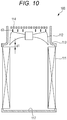
outdoor unit 100 illustrated inFig. 10 has a rectangular parallelepiped housing. The housing has abottom surface 117, side surfaces, and an upper surface. Anoutdoor heat exchanger 111 is arranged along the side surfaces of the housing. A blowingfan 112 is arranged on the upper surface of the housing. - An axial fan (a radial fan) is used as the blowing
fan 112. An air blowing direction of the blowingfan 112 is substantially perpendicular to thebottom surface 117 of the housing. The blowingfan 112 is placed on the upper surface of the housing. Abell mouth 113 is arranged around the blowingfan 112. Thebell mouth 113 is configured to adjust and stabilize an air flow. Thebell mouth 113 is provided with afan guard 114 such that thefan guard 114 covers an upper portion of the blowingfan 112. - In this
outdoor unit 100, when the blowingfan 112 is in operation, ambient air is sucked into the housing through the side surface of the housing while heat is being exchanged between the ambient air and refrigerant at theoutdoor heat exchanger 111. Thereafter, the air is blown from the upper surface of the housing (see, e.g.,JP-A-2010-127595 - In many cases, the upward blow type outdoor unit is placed on the roof of the building. The outdoor unit is normally delivered to the roof of the building by a freight elevator. The freight elevator has restriction on the size of goods to be delivered. For this reason, the packing size of the outdoor unit needs to be a size (specifically, a height) placeable on the freight elevator.
- Considering the thickness of a pallet for delivery by a forklift and a clearance upon lifting of the outdoor unit in the elevator by way of example, predetermined restriction is placed on the packing size (specifically, the height) of the outdoor unit.
- For preventing contact of an air current, a distance d1 between the
outdoor heat exchanger 111 and the blowingfan 112 and a distance d2 between the blowingfan 112 and thefan guard 114 are preferably long in the upward blow type outdoor unit. - However, the height of the outdoor unit is restricted by the above-described packing size. For this reason, it is difficult to increase the distance d1 between the
outdoor heat exchanger 111 and the blowingfan 112 and the distance d2 between the blowingfan 112 and thefan guard 114. Thus, contact of the air current is easily caused. - An outdoor unit of an air conditioner includes: a housing including a bottom surface, a side surface, and an upper surface; an outdoor heat exchanger arranged along the side surface of the housing; a blowing fan arranged on the upper surface of the housing; a bell mouth arranged around the blowing fan; a fan guard provided to cover an upper portion of the blowing fan; and a height changing member provided between the fan guard and the bell mouth and configured to change a height of the fan guard with respect to the blowing fan.
-
-
Fig. 1 is a perspective view of an outer appearance of an outdoor unit of an air conditioner according to one embodiment of the present disclosure; -
Fig. 2A is a schematic view of the outdoor unit whose height is decreased upon delivery, andFig. 2B is a schematic view of the outdoor unit whose height is increased at an installation location; -
Fig. 3A is an exploded perspective view of a height changing member applied to the outdoor unit in the first embodiment, andFig. 3B is a schematic view of an upper surface of a bell mouth with a fan guard being detached; -
Fig. 4A is a schematic view of the outdoor unit whose height is decreased upon delivery in the first embodiment,Fig. 4B is a sectional view along line A1-A1 ofFig. 3B , andFig. 4C is a sectional view along line B1-B1 ofFig. 3B ; -
Fig. 5A is a schematic view of the outdoor unit whose height is increased at the installation location in the first embodiment,Fig. 5B is a sectional view along line A1-A1 ofFig. 3B , andFig. 5C is a sectional view along line B1-B1 ofFig. 3B ; -
Fig. 6A is a sectional view of a first example of screwing of the fan guard to the bell mouth, andFig. 6B is a sectional view of a second example; -
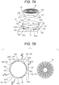
Fig. 7A is an exploded perspective view of a height changing member applied to an outdoor unit in a second embodiment, andFig. 7B is a schematic view of an upper surface of a bell mouth with a fan guard being detached; -
Fig. 8A is a schematic view of the outdoor unit whose height is decreased upon delivery in the second embodiment,Fig. 8B is a sectional view along line A2-A2 ofFig. 7B , andFig. 8C is a sectional view along line B2-B2 ofFig. 7B ; -
Fig. 9A is a schematic view of the outdoor unit whose height is increased at an installation location in the second embodiment,Fig. 9B is a sectional view along line A2-A2 ofFig. 7B , andFig. 9C is a sectional view along line B2-B2 ofFig. 7B ; and -
Fig. 10 is a schematic view of a typical outdoor unit in a packing size with a decreased height. - In the following detailed description, for purpose of explanation, numerous specific details are set forth in order to provide a thorough understanding of the disclosed embodiments. It will be apparent, however, that one or more embodiments may be practiced without these specific details. In other instances, well-known structures and devices are schematically shown in order to simplify the drawing.
- An object of the present disclosure is to provide an upward blow type outdoor unit in an air conditioner, the outdoor unit being configured so that the height of the outdoor unit can be decreased upon delivery to an installation location and can be, after delivery, increased back at the installation location to improve performance.
- An outdoor unit of an air conditioner according to one aspect of the present disclosure (the present outdoor unit) includes: a housing including a bottom surface, a side surface, and an upper surface; an outdoor heat exchanger arranged along the side surface of the housing; a blowing fan arranged on the upper surface of the housing; a bell mouth arranged around the blowing fan; a fan guard provided to cover an upper portion of the blowing fan; and a height changing member provided between the fan guard and the bell mouth and configured to change a height of the fan guard with respect to the blowing fan.
- According to a preferred embodiment of the present outdoor unit, the fan guard includes a support frame to be fitted onto the bell mouth, the height changing member includes multiple first raised portions formed at a predetermined interval along a circumferential direction of the bell mouth on a side surface of the bell mouth, and second raised portions formed to protrude downward from a lower side of the support frame and formed at an interval substantially equal to that of the first raised portions along a circumferential direction of the support frame, and the first raised portions and the second raised portions are configured such that each second raised portion is arranged between adjacent ones of the first raised portions or arranged on a corresponding one of the first raised portions.
- According to another embodiment of the present outdoor unit, each first raised portion may include a first slope as a rising slope along the circumferential direction of the bell mouth from a second side of another one of the first raised portions adjacent to a first side of the each first raised portion, each second raised portion may include a second slope as a slope parallel with the first slope, and the first raised portions and the second raised portions may be configured such that each second raised portion is, in association with rotation of the fan guard, guided by the first slope and the second slope to move onto a corresponding one of the first raised portions.
- According to the outdoor unit of the present disclosure, the support frame to be fitted in the bell mouth is attached to the fan guard. Further, the height changing member configured to change the height of the fan guard with respect to the blowing fan is provided between the bell mouth and the support frame. With this configuration, the fan guard is, upon delivery (shipment) of the present outdoor unit, moved closer to the blowing fan so that the height of the present outdoor unit can be decreased. Further, upon installation of the present outdoor unit after delivery, the fan guard is moved in a direction apart from the blowing fan so that the fan guard can be separated from the blowing fan to increase a distance between these components. With this configuration, contact of an air current can be reduced.
- An embodiment of the present disclosure will be described with reference to the drawings. Note that the technique of the present disclosure is not limited to such an embodiment.
- As illustrated in
Fig. 1 , anoutdoor unit 1 of an air conditioner according to this embodiment includes a substantiallyrectangular parallelepiped housing 10. Thehousing 10 includes abottom surface 17, side surfaces 18, and anupper surface 19. Anoutdoor heat exchanger 11 is arranged along three of the fourside surfaces 18 of thehousing 10. Two upper andlower service panels 16 are provided at the remainingside surface 18. Theservice panels 16 are opened/closed upon maintenance of the inside of thehousing 10. Theservice panels 16 are optional components. - The
upper surface 19 of thehousing 10 is provided with anair outlet 15. Referring toFigs. 1 ,2A, and 2B , a blowingfan 12 as an axial fan is placed in theair outlet 15 such that an air blowing direction thereof is substantially perpendicular to thebottom surface 17. - A
bell mouth 13 is arranged coaxially with the blowingfan 12 around the blowingfan 12. Thebell mouth 13 is configured to adjust and stabilize an air flow. Thebell mouth 13 is provided with afan guard 14 such that thefan guard 14 covers an upper portion of the blowingfan 12. The height of theoutdoor unit 1 is a dimension from the bottom surface 17 (a bottom plate of the bottom surface 17) to thefan guard 14. Note that thehousing 10 may be in a cylindrical shape. - In the present embodiment, the size of the
outdoor unit 1 is a packing size upon delivery (factory shipment). That is, thefan guard 14 is moved closer to the blowingfan 12 as illustrated inFig. 2A . Accordingly, the height of theoutdoor unit 1 reaches a smaller height h1. On the other hand, thefan guard 14 is, at an installation location, moved apart from the blowingfan 12 as illustrated inFig. 2B . Accordingly, the height of theoutdoor unit 1 can reach a greater height h2. - In the present embodiment, the
fan guard 14 includes, at a peripheral edge thereof, asupport frame 20 as illustrated inFigs. 3A and 3B . Thesupport frame 20 has a skirt shape. Thesupport frame 20 is attached to thebell mouth 13 with thesupport frame 20 being rotatable relative to thebell mouth 13 and being movable in an axial direction of thebell mouth 13. Thesupport frame 20 is preferably fitted onto an outer peripheral side of thebell mouth 13. Thebell mouth 13 and thesupport frame 20 may be made of metal or synthetic resin, for example. - A height changing member is provided between the
bell mouth 13 and thesupport frame 20. The height changing member is configured to change the height of thefan guard 14 with respect to the blowingfan 12. - The height changing member of the present embodiment includes a combination of raised
portions 131 provided on a side surface (an outer peripheral surface) of thebell mouth 13 and raisedportions 210 provided at thesupport frame 20. For the sake of convenience of description, the raisedportion 131 on abell mouth 13 side will be referred to as a "first raisedportion 131," and the raisedportion 210 on asupport frame 20 side will be referred to as a "second raisedportion 210." - The first raised
portions 131 are arranged at multiple points of the side surface of thebell mouth 13. In an illustrated example, the first raisedportions 131 are arranged at four points of the side surface of thebell mouth 13 at a center angle interval of 90°. A recessed portion (a first recessed portion) 133 is relatively formed between adjacent ones of the first raisedportions 131. - The first raised
portion 131 is formed in such a manner that a portion of a peripheral wall of thebell mouth 13 projects outward in a radial direction (seeFig. 4B ). Anupper surface 131 a of the first raisedportion 131 is a flat surface substantially parallel with thebottom surface 17. - The second raised
portions 210 on thesupport frame 20 side are arranged at multiple points of a lower side of thesupport frame 20. In the illustrated example, the second raisedportions 210 are arranged at four points of the lower side of thesupport frame 20 at a center angle interval of 90°. A recessed portion (a second recessed portion) 220 is relatively formed between adjacent ones of the second raisedportions 210. - In this embodiment, the length (the width) of the first raised
portion 131 along a circumferential direction of thebell mouth 13 is substantially 1/8 (the substantially 1/8 perimeter) of the length of the circumference of thebell mouth 13. Thus, the length (the width) of the first recessedportion 133 along the circumferential direction of thebell mouth 13 is also a substantially 1/8 perimeter. - On the other hand, the length (the width) of the second raised
portion 210 along a circumferential direction of thesupport frame 20 may be substantially 1/8 (the substantially 1/8 perimeter) of the length of the circumference of thesupport frame 20, but is preferably shorter than the 1/8 perimeter. Thus, the length (the width) of the second recessedportion 220 along the circumferential direction of thesupport frame 20 is relatively the substantially 1/8 perimeter or longer. - As illustrated in
Figs. 4A to 4C , the second raisedportions 210 of thesupport frame 20 are each fitted in the first recessedportions 133 of thebell mouth 13. Further, the first raisedportions 131 of thebell mouth 13 are each fitted in the second recessedportions 220 of thesupport frame 20. Accordingly, the height of theoutdoor unit 1 reaches the height h1 as the packing size upon delivery (factory shipment) as illustrated inFig. 2A . That is, thefan guard 14 is moved closer to the blowingfan 12 so that the height of theoutdoor unit 1 can reach the smaller height h1. - When the
support frame 20 is lifted and rotated substantially 45° from this state, the second raisedportions 210 of thesupport frame 20 are each placed on theupper surfaces 131a of the first raisedportions 131 of thebell mouth 13 as illustrated inFigs. 5A to 5C . Accordingly, the height of theoutdoor unit 1 reaches the height h2 at the installation location (a delivery destination) as illustrated inFig. 2B . That is, thefan guard 14 is, upon installation of theoutdoor unit 1, moved apart from the blowingfan 12 so that the height of theoutdoor unit 1 can reach the greater height h2. - As described above, in the present embodiment, the first raised
portions 131 and the second raisedportions 210 are configured such that each second raisedportion 210 is arranged between adjacent ones of the first raisedportions 131 or arranged on a corresponding one of the first raisedportions 131. Thus, according to the present embodiment, when the height of theoutdoor unit 1 is changed to the height as the packing size upon delivery, thefan guard 14 can be moved closer to the blowingfan 12. With this configuration, even when the height of theoutdoor unit 1 is decreased as illustrated inFig. 2A , a distance d1 between theoutdoor heat exchanger 11 and the blowingfan 12 can be increased (i.e., a long distance can be maintained). - On the other hand, when the
outdoor unit 1 is placed at the installation location (the delivery destination), thefan guard 14 can be moved apart from the blowingfan 12. With this configuration, a distance d2 between the blowingfan 12 and thefan guard 14 can be increased as illustrated inFig. 2B , and therefore, performance of the outdoor unit can be improved. Note that when the distance d2 is increased only by about 5 cm by way of example, it can be expected that contact of an air current is reduced and performance of the outdoor unit is improved. - Note that the length (the width) of each of the first raised
portions 131, the first recessedportions 133, the second raisedportions 210, and the second recessedportions 220 along the circumferential direction may be such a length that fitting between the first raisedportion 131 and the second recessedportion 220 and fitting between the second raisedportion 210 and the first recessedportion 133 can be simultaneously made. Moreover, the first raisedportions 131 may be provided at at least two points of the side surface of thebell mouth 13 at a center angle interval of 180°. Further, the second raisedportions 210 may be provided at at least two points of the lower side of thesupport frame 20 at a center angle interval of 180°. - In addition, in a case where the
fan guard 14 is attached to theoutdoor unit 1 at the installation location, thesupport frame 20 is preferably fixed to thebell mouth 13 for reducing noise such as chattering noise due to vibration of thesupport frame 20. Two examples of this case will be described with reference toFigs. 6A and 6B . - In the first example, the second raised
portion 210 of thesupport frame 20 is screwed to anupper edge portion 131b of thebell mouth 13 with an external thread S as illustrated inFig. 6A . - In the second example, a lower end of the second raised
portion 210 of thesupport frame 20 is bent in an L-shape as illustrated inFig. 6B . Thus, aflange 210a facing theupper surface 131a of the first raisedportion 131 is formed. Theflange 210a is screwed to theupper surface 131a of the first raisedportion 131 with an external thread S. - In comparison between these two examples, a tip end of the external thread S protrudes closer to a blade of the blowing
fan 12 in thebell mouth 13 in the case of the first example. For this reason, the second example is more preferable. - Next, a second embodiment will be described with reference to
Figs. 7A, 7B ,8A, 8B ,9A, and 9B . In the second embodiment, afan guard 14 is rotated relative to abell mouth 13 in a predetermined direction so that thefan guard 14 can be moved in a direction apart from a blowingfan 12. - As illustrated in
Fig. 7A , thebell mouth 13 is also provided with multiple first raisedportions 131 in the second embodiment. Note that each first raisedportion 131 is formed in a ratchet gear shape. - That is, a
first slope 132 is formed between a top portion of afirst side 131L (the left side inFig. 7A ) of each first raisedportion 131 and a bottom portion of asecond side 131R (the right side inFig. 7A ) of the first raisedportion 131 adjacent to thefirst side 131L. Thefirst slope 132 is a rising slope along a circumferential direction (counterclockwise inFig. 7A ) of thebell mouth 13. - With this configuration, a first recessed
portion 133 is in a right-angled triangular shape having, as two sides thereof, theside 131R of the first raisedportion 131 and thefirst slope 132 and opening on an upper side. Note that thefirst slope 132 may be a slope starting from a point apart from the bottom portion of theside 131R of the first raisedportion 131. - Moreover, a
second slope 211 as a slope parallel (or substantially parallel) with thefirst slope 132 is also provided on a lower side of each second raisedportion 210 of asupport frame 20. - According to the second embodiment, as illustrated in
Fig. 8A , the second raisedportions 210 are each fitted in the first recessedportions 133 such that thesecond slopes 211 each contact the first slopes 132. With this configuration, the height of anoutdoor unit 1 reaches a height h1 as a packing size upon delivery (factory shipment) as illustrated inFig. 2A . That is, thefan guard 14 is moved closer to the blowingfan 12 so that the height of theoutdoor unit 1 can reach the smaller height h1. - The
support frame 20 is rotated in a predetermined direction (a counterclockwise direction inFig. 8A ) from this state. Accordingly, each second raisedportion 210 is guided by a corresponding one of thefirst slopes 132 and a corresponding one of thesecond slopes 211, and therefore, moves over anupper surface 131a of a corresponding one of the first raisedportion 131 as illustrated inFig. 9A . Thus, the height of theoutdoor unit 1 reaches a height h2 at an installation location (a delivery destination) as illustrated inFig. 2B . That is, thefan guard 14 is, upon installation of theoutdoor unit 1, moved apart from the blowingfan 12 as illustrated inFig. 2B so that the height of theoutdoor unit 1 can reach the greater height h2. - As described above, in the present embodiment, the first raised
portions 131 and the second raisedportions 210 are configured such that each second raisedportion 210 is, in association with rotation of thefan guard 14, guided by a corresponding one of thefirst slopes 132 and a corresponding one of thesecond slopes 211 to move onto a corresponding one of the first raisedportions 131. - As described above, according to the embodiments of the present disclosure, the
fan guard 14 is moved closer to the blowingfan 12 so that the height of theoutdoor unit 1 can be decreased. With this configuration, theoutdoor unit 1 can be delivered with thefan guard 14 being attached to thebell mouth 13. Thus, theoutdoor unit 1 is in the packing size upon delivery of theoutdoor unit 1, and therefore, it is not necessary to detach thefan guard 14 from thebell mouth 13 to decrease the height of theoutdoor unit 1 and to attach thefan guard 14 after on-site installation of theoutdoor unit 1. - The embodiments of the present disclosure may be the following first to third outdoor units.
- The first outdoor unit is an outdoor unit of an air conditioner which includes a housing having a bottom surface, side surfaces, an upper surface and which is configured such that an outdoor heat exchanger is arranged along the side surfaces of the housing, that a blowing fan is arranged on the upper surface of the housing, that a bell mouth is arranged around the blowing fan, and that a fan guard is provided to cover an upper portion of the blowing fan. In this outdoor unit, a height changing member configured to change the height of the fan guard with respect to the blowing fan is provided between the fan guard and the bell mouth.
- The second outdoor unit is the first outdoor unit in which the fan guard includes a support frame to be fitted onto the bell mouth, the height changing member includes multiple first raised portions formed at a predetermined interval along a circumferential direction of the bell mouth on a side surface of the bell mouth, and second raised portions formed to protrude downward from a lower side of the support frame and formed at an interval substantially equal to that of the first raised portions along a circumferential direction of the support frame, and the height of the fan guard is different between arrangement of each second raised portion between adjacent ones of the first raised portions and arrangement of each second raised portion on a corresponding one of the first raised portions.
- The third outdoor unit is the second outdoor unit in which each first raised portion includes a first slope as a rising slope along the circumferential direction from one side of another one of the first raised portions adjacent to the other side of the each first raised portion, each second raised portion includes a second slope as a slope parallel with the first slope, and each second raised portion is, in association with rotation of the fan guard, guided by the first and second slopes to move onto a corresponding one of the first raised portions.
- The foregoing detailed description has been presented for the purposes of illustration and description. Many modifications and variations are possible in light of the above teaching. It is not intended to be exhaustive or to limit the subject matter described herein to the precise form disclosed. Although the subject matter has been described in language specific to structural features and/or methodological acts, it is to be understood that the subject matter defined in the appended claims is not necessarily limited to the specific features or acts described above. Rather, the specific features and acts described above are disclosed as example forms of implementing the claims appended hereto.
Claims (3)
- An outdoor unit (1) of an air conditioner, comprising:a housing (10) including a bottom surface (17), a side surface (18), and an upper surface (19);an outdoor heat exchanger (11) arranged along the side surface of the housing;a blowing fan (12) arranged on the upper surface of the housing;a bell mouth (13) arranged around the blowing fan;a fan guard (14) provided to cover an upper portion of the blowing fan; anda height changing member (131, 210) provided between the fan guard and the bell mouth and configured to change a height of the fan guard with respect to the blowing fan.
- The outdoor unit of the air conditioner according to claim 1, wherein
the fan guard includes a support frame (20) to be fitted onto the bell mouth,
the height changing member includesmultiple first raised portions (131) formed at a predetermined interval along a circumferential direction of the bell mouth on a side surface of the bell mouth, andsecond raised portions (210) formed to protrude downward from a lower side of the support frame and formed at an interval substantially equal to that of the first raised portions along a circumferential direction of the support frame, andthe first raised portions and the second raised portions are configured such that each second raised portion is arranged between adjacent ones of the first raised portions or arranged on a corresponding one of the first raised portions. - The outdoor unit of the air conditioner according to claim 2, wherein
each first raised portion includes a first slope (132) as a rising slope along the circumferential direction of the bell mouth from a second side of another one of the first raised portions adjacent to a first side of the each first raised portion,
each second raised portion includes a second slope (211) as a slope parallel with the first slope, and
the first raised portions and the second raised portions are configured such that each second raised portion is, in association with rotation of the fan guard, guided by the first slope and the second slope to move onto a corresponding one of the first raised portions.
Applications Claiming Priority (1)
| Application Number | Priority Date | Filing Date | Title |
|---|---|---|---|
| JP2017049400A JP6879458B2 (en) | 2017-03-15 | 2017-03-15 | Outdoor unit of air conditioner |
Publications (2)
| Publication Number | Publication Date |
|---|---|
| EP3376125A1 true EP3376125A1 (en) | 2018-09-19 |
| EP3376125B1 EP3376125B1 (en) | 2021-06-16 |
Family
ID=61223852
Family Applications (1)
| Application Number | Title | Priority Date | Filing Date |
|---|---|---|---|
| EP18156790.0A Active EP3376125B1 (en) | 2017-03-15 | 2018-02-14 | Outdoor unit of air conditioner |
Country Status (5)
| Country | Link |
|---|---|
| US (1) | US10495329B2 (en) |
| EP (1) | EP3376125B1 (en) |
| JP (1) | JP6879458B2 (en) |
| CN (1) | CN108626813B (en) |
| AU (1) | AU2018201314B2 (en) |
Cited By (1)
| Publication number | Priority date | Publication date | Assignee | Title |
|---|---|---|---|---|
| US20230160584A1 (en) * | 2020-12-03 | 2023-05-25 | Gd Midea Heating & Ventilating Equipment Co., Ltd. | Air conditioner outdoor unit |
Families Citing this family (7)
| Publication number | Priority date | Publication date | Assignee | Title |
|---|---|---|---|---|
| CN111853967A (en) * | 2019-04-26 | 2020-10-30 | 珠海格力电器股份有限公司 | Air conditioner casing and be equipped with its air conditioner |
| CN113007818A (en) * | 2019-12-20 | 2021-06-22 | 青岛海信日立空调系统有限公司 | Air conditioner |
| CN112577127A (en) * | 2020-12-21 | 2021-03-30 | 广州超卓机电工程有限公司 | Domestic hanging air conditioner |
| WO2023007603A1 (en) * | 2021-07-28 | 2023-02-02 | 三菱電機株式会社 | Outdoor unit and refrigeration cycle device |
| KR102850146B1 (en) * | 2022-11-16 | 2025-08-25 | 주식회사 더원리빙 | Suction device with double separation cylinder mesh |
| JP7540481B2 (en) * | 2022-12-27 | 2024-08-27 | 株式会社富士通ゼネラル | Outdoor units and air conditioners |
| CN117053297A (en) * | 2023-09-25 | 2023-11-14 | 广东美的暖通设备有限公司 | Air conditioning outdoor units and air conditioners |
Citations (5)
| Publication number | Priority date | Publication date | Assignee | Title |
|---|---|---|---|---|
| JPH09229421A (en) * | 1996-02-22 | 1997-09-05 | Sanyo Electric Co Ltd | Air conditioner |
| KR20090130670A (en) * | 2008-06-16 | 2009-12-24 | 삼성전자주식회사 | Outdoor unit of air conditioner |
| JP2010127595A (en) | 2008-12-01 | 2010-06-10 | Fujitsu General Ltd | Outdoor unit of air conditioner |
| US8092156B2 (en) * | 2007-10-31 | 2012-01-10 | Lg Electronics Inc. | Outdoor unit of air conditioner |
| WO2015152497A1 (en) * | 2014-03-31 | 2015-10-08 | 주식회사 에스제이환경산업 | Discharge air guide for outdoor unit of air conditioner |
Family Cites Families (25)
| Publication number | Priority date | Publication date | Assignee | Title |
|---|---|---|---|---|
| JPS5173752U (en) * | 1974-12-06 | 1976-06-10 | ||
| US4307778A (en) * | 1980-04-11 | 1981-12-29 | Carrier Corporation | Heat exchange unit having an internal support |
| US4899647A (en) * | 1988-12-22 | 1990-02-13 | Webb Mfg., Inc. | Ventilator system |
| JP3433085B2 (en) * | 1998-01-19 | 2003-08-04 | 株式会社日立製作所 | Outdoor unit of air conditioner |
| JP4462389B2 (en) * | 1998-11-20 | 2010-05-12 | 株式会社富士通ゼネラル | Air conditioner |
| CN100365346C (en) * | 2004-11-29 | 2008-01-30 | 乐金电子(天津)电器有限公司 | Indoor unit of air conditioner with diffuser |
| US7300248B2 (en) * | 2005-05-17 | 2007-11-27 | Cliff Wang | Ceiling fan assembly |
| JP2007163025A (en) * | 2005-12-14 | 2007-06-28 | Hitachi Ltd | Air conditioner outdoor unit |
| CN101109544A (en) * | 2006-07-19 | 2008-01-23 | 乐金电子(天津)电器有限公司 | Air conditioner |
| KR20090043715A (en) * | 2007-10-30 | 2009-05-07 | 삼성전자주식회사 | Fan guard and outdoor unit of air conditioner having same |
| JP2010127594A (en) * | 2008-12-01 | 2010-06-10 | Fujitsu General Ltd | Outdoor unit of air conditioner |
| CN201373533Y (en) * | 2009-01-10 | 2009-12-30 | 广东美的电器股份有限公司 | An outdoor unit of a top air conditioner |
| JP5322900B2 (en) * | 2009-11-27 | 2013-10-23 | 三洋電機株式会社 | Bell mouth structure of blower |
| JP5310829B2 (en) * | 2011-11-30 | 2013-10-09 | ダイキン工業株式会社 | Casing of outdoor unit in air conditioner |
| CN203518171U (en) * | 2013-11-13 | 2014-04-02 | 中国扬子集团滁州扬子空调器有限公司 | Outdoor unit housing suitable for heat exchangers with various lengths and heights |
| JP6385752B2 (en) * | 2013-12-02 | 2018-09-05 | 三星電子株式会社Samsung Electronics Co.,Ltd. | Outdoor unit for blower and air conditioner |
| KR102272056B1 (en) * | 2014-09-25 | 2021-07-05 | 삼성전자주식회사 | Outdoor Unit Of Air Conditioner And Thereof Control Method |
| CN104279650B (en) * | 2014-09-29 | 2017-02-01 | 美的集团武汉制冷设备有限公司 | Front panel component of outdoor unit of air conditioner |
| CN104748335A (en) * | 2014-12-16 | 2015-07-01 | 南京佳力图空调机电有限公司 | Computer room air conditioner fan mounting mechanism |
| JP5957100B2 (en) * | 2015-01-14 | 2016-07-27 | シャープ株式会社 | Air conditioner |
| US11022327B2 (en) * | 2015-05-14 | 2021-06-01 | Mitsubishi Electric Corporation | Outdoor unit of air-conditioning apparatus |
| HUE056340T2 (en) * | 2015-09-29 | 2022-02-28 | Kaip Pty Ltd | Air diffuser |
| US10495328B2 (en) * | 2015-11-02 | 2019-12-03 | Mitsubishi Electric Corporation | Outdoor unit of air conditioner and refrigeration cycle device |
| CN205137736U (en) * | 2015-11-17 | 2016-04-06 | 广东美的暖通设备有限公司 | Heat sink component and air conditioner |
| JP6482679B2 (en) * | 2015-11-30 | 2019-03-13 | 三菱電機株式会社 | Outdoor unit |
-
2017
- 2017-03-15 JP JP2017049400A patent/JP6879458B2/en active Active
-
2018
- 2018-02-14 EP EP18156790.0A patent/EP3376125B1/en active Active
- 2018-02-20 US US15/900,097 patent/US10495329B2/en active Active
- 2018-02-23 AU AU2018201314A patent/AU2018201314B2/en active Active
- 2018-03-15 CN CN201810213548.2A patent/CN108626813B/en active Active
Patent Citations (5)
| Publication number | Priority date | Publication date | Assignee | Title |
|---|---|---|---|---|
| JPH09229421A (en) * | 1996-02-22 | 1997-09-05 | Sanyo Electric Co Ltd | Air conditioner |
| US8092156B2 (en) * | 2007-10-31 | 2012-01-10 | Lg Electronics Inc. | Outdoor unit of air conditioner |
| KR20090130670A (en) * | 2008-06-16 | 2009-12-24 | 삼성전자주식회사 | Outdoor unit of air conditioner |
| JP2010127595A (en) | 2008-12-01 | 2010-06-10 | Fujitsu General Ltd | Outdoor unit of air conditioner |
| WO2015152497A1 (en) * | 2014-03-31 | 2015-10-08 | 주식회사 에스제이환경산업 | Discharge air guide for outdoor unit of air conditioner |
Cited By (1)
| Publication number | Priority date | Publication date | Assignee | Title |
|---|---|---|---|---|
| US20230160584A1 (en) * | 2020-12-03 | 2023-05-25 | Gd Midea Heating & Ventilating Equipment Co., Ltd. | Air conditioner outdoor unit |
Also Published As
| Publication number | Publication date |
|---|---|
| CN108626813A (en) | 2018-10-09 |
| AU2018201314B2 (en) | 2023-03-30 |
| JP2018151144A (en) | 2018-09-27 |
| CN108626813B (en) | 2021-03-19 |
| US10495329B2 (en) | 2019-12-03 |
| US20180266707A1 (en) | 2018-09-20 |
| AU2018201314A1 (en) | 2018-10-04 |
| EP3376125B1 (en) | 2021-06-16 |
| JP6879458B2 (en) | 2021-06-02 |
Similar Documents
| Publication | Publication Date | Title |
|---|---|---|
| AU2018201314B2 (en) | Outdoor unit of air conditioner | |
| US20140043733A1 (en) | Ceiling mount occupancy sensor module and apparatus using the ceiling mount occupancy sensor module | |
| AU2018288739B2 (en) | Air conditioning indoor unit | |
| US11746798B2 (en) | Centrifugal fan | |
| US9982908B2 (en) | Air conditioner | |
| US20110211948A1 (en) | Fan bracket and fan fixing apparatus using the same | |
| WO2012130100A1 (en) | Ventilating fan | |
| JP6128507B2 (en) | Sunshade cover for air conditioner outdoor unit | |
| CN106765607B (en) | Air conditioner and indoor unit thereof | |
| JP6271225B2 (en) | Air conditioner outdoor unit | |
| JP2011052887A (en) | Air supply grille | |
| JP5317515B2 (en) | Ventilation system | |
| JP2011052886A (en) | Air supply grille | |
| CN108429378A (en) | plastic package motor and air conditioner | |
| US20130010420A1 (en) | Bracket for expansion card and electronic device having the same | |
| JP2014190655A (en) | Four-way cassette air conditioner | |
| JP3184434U (en) | Control unit box | |
| JPWO2022091436A5 (en) | ||
| CN107965897B (en) | Air conditioner air outlet device | |
| EP3524893B1 (en) | Outdoor unit of air conditioner | |
| CN223219345U (en) | Shutter and cabinet | |
| JP2000227097A (en) | Wind direction control device of fan | |
| KR200198161Y1 (en) | A consolidating structure of outdoor unit for seperated type air conditioner | |
| CN110820265B (en) | Wall-mounted laundry treatment equipment | |
| CN207132444U (en) | Indoor apparatus of air conditioner |
Legal Events
| Date | Code | Title | Description |
|---|---|---|---|
| PUAI | Public reference made under article 153(3) epc to a published international application that has entered the european phase |
Free format text: ORIGINAL CODE: 0009012 |
|
| STAA | Information on the status of an ep patent application or granted ep patent |
Free format text: STATUS: THE APPLICATION HAS BEEN PUBLISHED |
|
| AK | Designated contracting states |
Kind code of ref document: A1 Designated state(s): AL AT BE BG CH CY CZ DE DK EE ES FI FR GB GR HR HU IE IS IT LI LT LU LV MC MK MT NL NO PL PT RO RS SE SI SK SM TR |
|
| AX | Request for extension of the european patent |
Extension state: BA ME |
|
| STAA | Information on the status of an ep patent application or granted ep patent |
Free format text: STATUS: REQUEST FOR EXAMINATION WAS MADE |
|
| 17P | Request for examination filed |
Effective date: 20190319 |
|
| RBV | Designated contracting states (corrected) |
Designated state(s): AL AT BE BG CH CY CZ DE DK EE ES FI FR GB GR HR HU IE IS IT LI LT LU LV MC MK MT NL NO PL PT RO RS SE SI SK SM TR |
|
| GRAP | Despatch of communication of intention to grant a patent |
Free format text: ORIGINAL CODE: EPIDOSNIGR1 |
|
| STAA | Information on the status of an ep patent application or granted ep patent |
Free format text: STATUS: GRANT OF PATENT IS INTENDED |
|
| RIC1 | Information provided on ipc code assigned before grant |
Ipc: F24F 1/38 20110101AFI20201204BHEP Ipc: F24F 1/56 20110101ALI20201204BHEP |
|
| INTG | Intention to grant announced |
Effective date: 20210104 |
|
| INTG | Intention to grant announced |
Effective date: 20210113 |
|
| GRAS | Grant fee paid |
Free format text: ORIGINAL CODE: EPIDOSNIGR3 |
|
| GRAA | (expected) grant |
Free format text: ORIGINAL CODE: 0009210 |
|
| STAA | Information on the status of an ep patent application or granted ep patent |
Free format text: STATUS: THE PATENT HAS BEEN GRANTED |
|
| AK | Designated contracting states |
Kind code of ref document: B1 Designated state(s): AL AT BE BG CH CY CZ DE DK EE ES FI FR GB GR HR HU IE IS IT LI LT LU LV MC MK MT NL NO PL PT RO RS SE SI SK SM TR |
|
| REG | Reference to a national code |
Ref country code: GB Ref legal event code: FG4D |
|
| REG | Reference to a national code |
Ref country code: CH Ref legal event code: EP |
|
| REG | Reference to a national code |
Ref country code: DE Ref legal event code: R096 Ref document number: 602018018525 Country of ref document: DE |
|
| REG | Reference to a national code |
Ref country code: AT Ref legal event code: REF Ref document number: 1402652 Country of ref document: AT Kind code of ref document: T Effective date: 20210715 |
|
| REG | Reference to a national code |
Ref country code: IE Ref legal event code: FG4D |
|
| REG | Reference to a national code |
Ref country code: LT Ref legal event code: MG9D |
|
| PG25 | Lapsed in a contracting state [announced via postgrant information from national office to epo] |
Ref country code: FI Free format text: LAPSE BECAUSE OF FAILURE TO SUBMIT A TRANSLATION OF THE DESCRIPTION OR TO PAY THE FEE WITHIN THE PRESCRIBED TIME-LIMIT Effective date: 20210616 Ref country code: LT Free format text: LAPSE BECAUSE OF FAILURE TO SUBMIT A TRANSLATION OF THE DESCRIPTION OR TO PAY THE FEE WITHIN THE PRESCRIBED TIME-LIMIT Effective date: 20210616 Ref country code: HR Free format text: LAPSE BECAUSE OF FAILURE TO SUBMIT A TRANSLATION OF THE DESCRIPTION OR TO PAY THE FEE WITHIN THE PRESCRIBED TIME-LIMIT Effective date: 20210616 Ref country code: BG Free format text: LAPSE BECAUSE OF FAILURE TO SUBMIT A TRANSLATION OF THE DESCRIPTION OR TO PAY THE FEE WITHIN THE PRESCRIBED TIME-LIMIT Effective date: 20210916 |
|
| REG | Reference to a national code |
Ref country code: AT Ref legal event code: MK05 Ref document number: 1402652 Country of ref document: AT Kind code of ref document: T Effective date: 20210616 |
|
| REG | Reference to a national code |
Ref country code: NL Ref legal event code: MP Effective date: 20210616 |
|
| PG25 | Lapsed in a contracting state [announced via postgrant information from national office to epo] |
Ref country code: GR Free format text: LAPSE BECAUSE OF FAILURE TO SUBMIT A TRANSLATION OF THE DESCRIPTION OR TO PAY THE FEE WITHIN THE PRESCRIBED TIME-LIMIT Effective date: 20210917 Ref country code: LV Free format text: LAPSE BECAUSE OF FAILURE TO SUBMIT A TRANSLATION OF THE DESCRIPTION OR TO PAY THE FEE WITHIN THE PRESCRIBED TIME-LIMIT Effective date: 20210616 Ref country code: NO Free format text: LAPSE BECAUSE OF FAILURE TO SUBMIT A TRANSLATION OF THE DESCRIPTION OR TO PAY THE FEE WITHIN THE PRESCRIBED TIME-LIMIT Effective date: 20210916 Ref country code: RS Free format text: LAPSE BECAUSE OF FAILURE TO SUBMIT A TRANSLATION OF THE DESCRIPTION OR TO PAY THE FEE WITHIN THE PRESCRIBED TIME-LIMIT Effective date: 20210616 Ref country code: SE Free format text: LAPSE BECAUSE OF FAILURE TO SUBMIT A TRANSLATION OF THE DESCRIPTION OR TO PAY THE FEE WITHIN THE PRESCRIBED TIME-LIMIT Effective date: 20210616 |
|
| PG25 | Lapsed in a contracting state [announced via postgrant information from national office to epo] |
Ref country code: PT Free format text: LAPSE BECAUSE OF FAILURE TO SUBMIT A TRANSLATION OF THE DESCRIPTION OR TO PAY THE FEE WITHIN THE PRESCRIBED TIME-LIMIT Effective date: 20211018 Ref country code: NL Free format text: LAPSE BECAUSE OF FAILURE TO SUBMIT A TRANSLATION OF THE DESCRIPTION OR TO PAY THE FEE WITHIN THE PRESCRIBED TIME-LIMIT Effective date: 20210616 Ref country code: RO Free format text: LAPSE BECAUSE OF FAILURE TO SUBMIT A TRANSLATION OF THE DESCRIPTION OR TO PAY THE FEE WITHIN THE PRESCRIBED TIME-LIMIT Effective date: 20210616 Ref country code: CZ Free format text: LAPSE BECAUSE OF FAILURE TO SUBMIT A TRANSLATION OF THE DESCRIPTION OR TO PAY THE FEE WITHIN THE PRESCRIBED TIME-LIMIT Effective date: 20210616 Ref country code: AT Free format text: LAPSE BECAUSE OF FAILURE TO SUBMIT A TRANSLATION OF THE DESCRIPTION OR TO PAY THE FEE WITHIN THE PRESCRIBED TIME-LIMIT Effective date: 20210616 Ref country code: SM Free format text: LAPSE BECAUSE OF FAILURE TO SUBMIT A TRANSLATION OF THE DESCRIPTION OR TO PAY THE FEE WITHIN THE PRESCRIBED TIME-LIMIT Effective date: 20210616 Ref country code: SK Free format text: LAPSE BECAUSE OF FAILURE TO SUBMIT A TRANSLATION OF THE DESCRIPTION OR TO PAY THE FEE WITHIN THE PRESCRIBED TIME-LIMIT Effective date: 20210616 Ref country code: ES Free format text: LAPSE BECAUSE OF FAILURE TO SUBMIT A TRANSLATION OF THE DESCRIPTION OR TO PAY THE FEE WITHIN THE PRESCRIBED TIME-LIMIT Effective date: 20210616 Ref country code: EE Free format text: LAPSE BECAUSE OF FAILURE TO SUBMIT A TRANSLATION OF THE DESCRIPTION OR TO PAY THE FEE WITHIN THE PRESCRIBED TIME-LIMIT Effective date: 20210616 |
|
| PG25 | Lapsed in a contracting state [announced via postgrant information from national office to epo] |
Ref country code: PL Free format text: LAPSE BECAUSE OF FAILURE TO SUBMIT A TRANSLATION OF THE DESCRIPTION OR TO PAY THE FEE WITHIN THE PRESCRIBED TIME-LIMIT Effective date: 20210616 |
|
| REG | Reference to a national code |
Ref country code: DE Ref legal event code: R097 Ref document number: 602018018525 Country of ref document: DE |
|
| PLBE | No opposition filed within time limit |
Free format text: ORIGINAL CODE: 0009261 |
|
| STAA | Information on the status of an ep patent application or granted ep patent |
Free format text: STATUS: NO OPPOSITION FILED WITHIN TIME LIMIT |
|
| PG25 | Lapsed in a contracting state [announced via postgrant information from national office to epo] |
Ref country code: DK Free format text: LAPSE BECAUSE OF FAILURE TO SUBMIT A TRANSLATION OF THE DESCRIPTION OR TO PAY THE FEE WITHIN THE PRESCRIBED TIME-LIMIT Effective date: 20210616 |
|
| 26N | No opposition filed |
Effective date: 20220317 |
|
| PG25 | Lapsed in a contracting state [announced via postgrant information from national office to epo] |
Ref country code: AL Free format text: LAPSE BECAUSE OF FAILURE TO SUBMIT A TRANSLATION OF THE DESCRIPTION OR TO PAY THE FEE WITHIN THE PRESCRIBED TIME-LIMIT Effective date: 20210616 |
|
| PG25 | Lapsed in a contracting state [announced via postgrant information from national office to epo] |
Ref country code: IT Free format text: LAPSE BECAUSE OF FAILURE TO SUBMIT A TRANSLATION OF THE DESCRIPTION OR TO PAY THE FEE WITHIN THE PRESCRIBED TIME-LIMIT Effective date: 20210616 |
|
| PG25 | Lapsed in a contracting state [announced via postgrant information from national office to epo] |
Ref country code: MC Free format text: LAPSE BECAUSE OF FAILURE TO SUBMIT A TRANSLATION OF THE DESCRIPTION OR TO PAY THE FEE WITHIN THE PRESCRIBED TIME-LIMIT Effective date: 20210616 |
|
| REG | Reference to a national code |
Ref country code: CH Ref legal event code: PL |
|
| REG | Reference to a national code |
Ref country code: BE Ref legal event code: MM Effective date: 20220228 |
|
| PG25 | Lapsed in a contracting state [announced via postgrant information from national office to epo] |
Ref country code: LU Free format text: LAPSE BECAUSE OF NON-PAYMENT OF DUE FEES Effective date: 20220214 |
|
| PG25 | Lapsed in a contracting state [announced via postgrant information from national office to epo] |
Ref country code: LI Free format text: LAPSE BECAUSE OF NON-PAYMENT OF DUE FEES Effective date: 20220228 Ref country code: IE Free format text: LAPSE BECAUSE OF NON-PAYMENT OF DUE FEES Effective date: 20220214 Ref country code: CH Free format text: LAPSE BECAUSE OF NON-PAYMENT OF DUE FEES Effective date: 20220228 |
|
| PG25 | Lapsed in a contracting state [announced via postgrant information from national office to epo] |
Ref country code: BE Free format text: LAPSE BECAUSE OF NON-PAYMENT OF DUE FEES Effective date: 20220228 |
|
| PG25 | Lapsed in a contracting state [announced via postgrant information from national office to epo] |
Ref country code: HU Free format text: LAPSE BECAUSE OF FAILURE TO SUBMIT A TRANSLATION OF THE DESCRIPTION OR TO PAY THE FEE WITHIN THE PRESCRIBED TIME-LIMIT; INVALID AB INITIO Effective date: 20180214 |
|
| PG25 | Lapsed in a contracting state [announced via postgrant information from national office to epo] |
Ref country code: MK Free format text: LAPSE BECAUSE OF FAILURE TO SUBMIT A TRANSLATION OF THE DESCRIPTION OR TO PAY THE FEE WITHIN THE PRESCRIBED TIME-LIMIT Effective date: 20210616 Ref country code: CY Free format text: LAPSE BECAUSE OF FAILURE TO SUBMIT A TRANSLATION OF THE DESCRIPTION OR TO PAY THE FEE WITHIN THE PRESCRIBED TIME-LIMIT Effective date: 20210616 |
|
| PG25 | Lapsed in a contracting state [announced via postgrant information from national office to epo] |
Ref country code: MT Free format text: LAPSE BECAUSE OF FAILURE TO SUBMIT A TRANSLATION OF THE DESCRIPTION OR TO PAY THE FEE WITHIN THE PRESCRIBED TIME-LIMIT Effective date: 20210616 |
|
| PG25 | Lapsed in a contracting state [announced via postgrant information from national office to epo] |
Ref country code: TR Free format text: LAPSE BECAUSE OF FAILURE TO SUBMIT A TRANSLATION OF THE DESCRIPTION OR TO PAY THE FEE WITHIN THE PRESCRIBED TIME-LIMIT Effective date: 20210616 |
|
| PGFP | Annual fee paid to national office [announced via postgrant information from national office to epo] |
Ref country code: GB Payment date: 20260218 Year of fee payment: 9 |
|
| PGFP | Annual fee paid to national office [announced via postgrant information from national office to epo] |
Ref country code: DE Payment date: 20260217 Year of fee payment: 9 |
|
| PGFP | Annual fee paid to national office [announced via postgrant information from national office to epo] |
Ref country code: FR Payment date: 20260213 Year of fee payment: 9 |