EP3376110A1 - Burner unit for a gas turbine electrical power plant, gas turbine electrical power plant comprising said burner unit and method for operating said gas turbine electrical power plant - Google Patents
Burner unit for a gas turbine electrical power plant, gas turbine electrical power plant comprising said burner unit and method for operating said gas turbine electrical power plant Download PDFInfo
- Publication number
- EP3376110A1 EP3376110A1 EP18161522.0A EP18161522A EP3376110A1 EP 3376110 A1 EP3376110 A1 EP 3376110A1 EP 18161522 A EP18161522 A EP 18161522A EP 3376110 A1 EP3376110 A1 EP 3376110A1
- Authority
- EP
- European Patent Office
- Prior art keywords
- burner
- swirler
- internal
- fuel
- external
- Prior art date
- Legal status (The legal status is an assumption and is not a legal conclusion. Google has not performed a legal analysis and makes no representation as to the accuracy of the status listed.)
- Granted
Links
Images


Classifications
-
- F—MECHANICAL ENGINEERING; LIGHTING; HEATING; WEAPONS; BLASTING
- F23—COMBUSTION APPARATUS; COMBUSTION PROCESSES
- F23R—GENERATING COMBUSTION PRODUCTS OF HIGH PRESSURE OR HIGH VELOCITY, e.g. GAS-TURBINE COMBUSTION CHAMBERS
- F23R3/00—Continuous combustion chambers using liquid or gaseous fuel
- F23R3/28—Continuous combustion chambers using liquid or gaseous fuel characterised by the fuel supply
- F23R3/38—Continuous combustion chambers using liquid or gaseous fuel characterised by the fuel supply comprising rotary fuel injection means
-
- F—MECHANICAL ENGINEERING; LIGHTING; HEATING; WEAPONS; BLASTING
- F23—COMBUSTION APPARATUS; COMBUSTION PROCESSES
- F23R—GENERATING COMBUSTION PRODUCTS OF HIGH PRESSURE OR HIGH VELOCITY, e.g. GAS-TURBINE COMBUSTION CHAMBERS
- F23R3/00—Continuous combustion chambers using liquid or gaseous fuel
- F23R3/28—Continuous combustion chambers using liquid or gaseous fuel characterised by the fuel supply
- F23R3/34—Feeding into different combustion zones
-
- F—MECHANICAL ENGINEERING; LIGHTING; HEATING; WEAPONS; BLASTING
- F23—COMBUSTION APPARATUS; COMBUSTION PROCESSES
- F23R—GENERATING COMBUSTION PRODUCTS OF HIGH PRESSURE OR HIGH VELOCITY, e.g. GAS-TURBINE COMBUSTION CHAMBERS
- F23R3/00—Continuous combustion chambers using liquid or gaseous fuel
- F23R3/02—Continuous combustion chambers using liquid or gaseous fuel characterised by the air-flow or gas-flow configuration
- F23R3/04—Air inlet arrangements
- F23R3/10—Air inlet arrangements for primary air
- F23R3/12—Air inlet arrangements for primary air inducing a vortex
- F23R3/14—Air inlet arrangements for primary air inducing a vortex by using swirl vanes
-
- F—MECHANICAL ENGINEERING; LIGHTING; HEATING; WEAPONS; BLASTING
- F23—COMBUSTION APPARATUS; COMBUSTION PROCESSES
- F23R—GENERATING COMBUSTION PRODUCTS OF HIGH PRESSURE OR HIGH VELOCITY, e.g. GAS-TURBINE COMBUSTION CHAMBERS
- F23R3/00—Continuous combustion chambers using liquid or gaseous fuel
- F23R3/28—Continuous combustion chambers using liquid or gaseous fuel characterised by the fuel supply
- F23R3/286—Continuous combustion chambers using liquid or gaseous fuel characterised by the fuel supply having fuel-air premixing devices
-
- F—MECHANICAL ENGINEERING; LIGHTING; HEATING; WEAPONS; BLASTING
- F23—COMBUSTION APPARATUS; COMBUSTION PROCESSES
- F23R—GENERATING COMBUSTION PRODUCTS OF HIGH PRESSURE OR HIGH VELOCITY, e.g. GAS-TURBINE COMBUSTION CHAMBERS
- F23R2900/00—Special features of, or arrangements for continuous combustion chambers; Combustion processes therefor
- F23R2900/00013—Reducing thermo-acoustic vibrations by active means
-
- F—MECHANICAL ENGINEERING; LIGHTING; HEATING; WEAPONS; BLASTING
- F23—COMBUSTION APPARATUS; COMBUSTION PROCESSES
- F23R—GENERATING COMBUSTION PRODUCTS OF HIGH PRESSURE OR HIGH VELOCITY, e.g. GAS-TURBINE COMBUSTION CHAMBERS
- F23R2900/00—Special features of, or arrangements for continuous combustion chambers; Combustion processes therefor
- F23R2900/03343—Pilot burners operating in premixed mode
Definitions
- the invention relates to a burner unit for a gas turbine plant, to a gas turbine plant comprising said burner unit and to a method for operating said gas turbine plant.
- combustion technique Due to stricter and stricter rules in terms of polluting emissions, the combustion technique has developed towards the use of combustion chambers structured according to the so-called "lean premix" technology. This technique involves the use of premix burners.
- Premix burners are supplied with an air-fuel mixture, with a strong excess of air, in order to generate a flame that is such as to ensure a uniform temperature field and avoid possible temperature peaks, which might lead to high NOx emission at the exhaust. By so doing, premix burners ensure a smaller quantity of polluting emissions.
- the flames generated by premix burners are more likely to be subjected to dynamic instabilities.
- the periodical fluctuations of the heat release can be associated with pressure fluctuations in the combustor, thus sustaining one another. If these fluctuations are coupled to the resonance frequencies of the mechanical components of the combustor, serious damages can be caused to the mechanical components themselves.
- Flame instabilities can be thermoacoustic or fluid-dynamic and these two types can interact with one another.
- Thermoacoustic instability phenomena are usually indicated with the term "humming".
- Fluid-dynamic instability phenomena mainly occur in burners operating with a vortex flow.
- An example of fluid-dynamic instability typical of this type of burners is the generation of a precessing vortex core (PVC).
- the object of the invention is to provide a burner unit, wherein flame instabilities are minimized and an acceptable level of polluting emissions is ensured.
- the invention relates to a burner unit for a combustor of a gas turbine electrical power plant; the burner unit extends around a longitudinal axis and comprises:
- a further object of the invention is to provide a gas turbine electrical power plant, which is stable and efficient and, at the same time, is capable of keeping polluting emission levels below the limits provided for by law.
- the invention relates to a gas turbine electrical power plant according to claim 10.
- a further object of the invention is to provide a method for operating a gas turbine electrical power plant, which is effective and capable of ensuring stability during the combustion as well as, at the same time, low polluting emission levels.
- the invention relates to a method for operating a gas turbine electrical power plant; the plant comprising a compressor, a gas turbine and a combustor provided with a least one burner unit; the burner unit comprising:
- number 1 indicates an electrical power plant comprising a gas turbine 2 extending along an axis A, a compressor 3, a combustor 4, a fuel supply unit 6 configured to supply fuel to the combustor 4, and a generator 7, which transforms the mechanical power provided by the gas turbine 2 into emitted electrical power.
- the combustor 4 preferably is annular and comprises a plurality of seats 8, each designed to be engaged by a burner unit 9 (which is better visible in figures 2-3 ).
- the seats 8 are arranged along a circular path close to a peripheral edge of the combustor 4. In the non-limiting embodiment described and discussed herein, there are twenty-four seats 8 and burner units 9.
- each burner unit 9 extends along an axis B and comprises an internal burner 10, an external burner 11, which extends around the internal burner 10, and an intermediate burner 12, which is arranged between the external burner 11 and the internal burner 10 around the internal burner 10.
- the internal burner 10 extends along the axis B or extends around the axis B so as to create a hollow space that is left free so that it can house possible auxiliary devices.
- the burner unit 9 further comprises an auxiliary device 14, which is arranged along the axis B, and the internal burner 10 extends around the auxiliary device 14.
- the auxiliary device 14 is supplied with air coming from the compressor 3.
- Variants that are not shown herein involve the use of an auxiliary device provided with at least one additional supply for a secondary fuel, such as for example natural gas or Diesel fuel.
- the internal burner 10, the external burner 11 and the intermediate burner 12 are supplied by the fuel supply unit 6.
- the fuel supply unit 6 is configured so that the internal burner 10, the external burner 11 and the intermediate burner 12 are supplied with fuel in an independent manner.
- the quantity of fuel supplied to the internal burner 10 can be regulated independently of the quantity of fuel supplied to the external burner 11 and to the intermediate burner 12, and vice versa.
- the fuel supply unit 6 comprises at least one first manifold 15, which is configured to supply fuel to the internal burners 10 (schematically shown in figure 3 ) of the burner units 9 of the combustor 4, a second manifold 16, which is configured to supply fuel to the external burners 11 (schematically shown in figure 3 ) of the burner units 9 of the combustor 4, and a third manifold 17, which is configured to supply fuel to the intermediate burners 12 (schematically shown in figure 3 ) of the burner units 9 of the combustor 4.
- first manifold 15 is configured to supply fuel to the internal burners 10 (schematically shown in figure 3 ) of the burner units 9 of the combustor 4
- a second manifold 16 which is configured to supply fuel to the external burners 11 (schematically shown in figure 3 ) of the burner units 9 of the combustor 4
- a third manifold 17 which is configured to supply fuel to the intermediate burners 12 (schematically shown in figure 3 ) of the burner units 9 of the comb
- the first manifold 15, the second manifold 16 and the third manifold 17 are connected to the same tank 20 by means of respective supply lines provided with respective regulating valves 21a, 21b, 21c.
- the quantity of fuel to be supplied to each manifold 15, 16, 17 can be regulated in an independent manner.
- the regulating valves 21a, 21b, 21c are connected to a control system (which is not shown in the accompanying drawings).
- the fuel in the tank 20 is natural gas.
- the internal burner 10, the external burner 11 and the intermediate burner 12 are supplied with air coming from the compressor 3 and with fuel coming from the fuel supply unit 6.
- the air and the fuel are supplied along a supply direction D1 directed towards the inside of the combustor 4.
- the internal burner 10 comprises an internal air supply channel 24 and an internal fuel supply channel 25 (which is partially visible in figure 2 ).
- the internal air supply channel 24 is an annular channel extending around the axis B and around the auxiliary device 14 and is supplied with air coming from the exhaust of the compressor 3.
- the internal air supply channel 24 is in communication with the inside of a case (not shown), which is supplied with air coming from the compressor 3.
- the internal air supply channel 24 is sized so as to supply a given air flow rate.
- an auxiliary regulating device 24a which is optional and is usually used to further regulate the flow rate flowing into the internal burner 10.
- the auxiliary regulating device 24a is a narrowing of the passageway section of the internal air supply channel 24 and is defined by a ring coupled to the internal surface of the wall which defines the internal air supply channel 24 and is proximal to the axis B.
- the auxiliary regulating device 24a is defined by a ring coupled to the internal surface of the wall which defines the internal air supply channel 24 and is distal relative to the axis B.
- an internal swirler 26 which is provided with a plurality of blades 27.
- the internal swirler 26 is arranged at the outlet of the internal air supply channel 24.
- the internal swirler 26 is a diagonal swirler.
- the internal swirler 26 is axial.
- diagonal swirler we mean a swirler where the blades extend between walls which are shaped so as to define a channel that is substantially transverse to the axis B (annular channel substantially shaped like a truncated cone), whereas by axial swirler we mean a swirler where the blades extend between walls which are substantially shaped so as to define a channel that is parallel to the axis B (substantially cylindrical annular channel).
- the internal fuel supply channel 25 is connected to the manifold 15 (which is not shown in figure 2 ) and is supplied with a given fuel flow rate QCI.
- the internal fuel supply channel 25 is an annular channel extending around the axis B and arranged between the auxiliary device 14 and the internal air supply channel 24 and is provided with a plurality of discharge nozzles 28 (only one of them can be seen in figure 2 ).
- the discharge nozzles 28 are positioned so as to lead between the blades of the internal swirler 26.
- the intermediate burner 12 comprises an intermediate air supply channel 30 and an intermediate fuel supply channel 31 (which is partially visible in figure 2 ).
- the intermediate air supply channel 30 is an annular channel extending around the axis B and around the internal burner 10 and is supplied with air coming from the exhaust of the compressor 3.
- the intermediate air supply channel 30 is in communication with the inside of a case (not shown), which is supplied with air coming from the compressor 3.
- the intermediate air supply channel 30 is sized so as to supply a given air flow rate QAIn.
- An intermediate swirler 32 is arranged along the intermediate air supply channel 30.
- the intermediate swirler 32 is a diagonal swirler provided with a plurality of blades 33.
- the intermediate swirler 32 is arranged close to the outlet of the intermediate air supply channel 30.
- the outlet of the intermediate swirler 32 is arranged upstream of the outlet of the internal swirler 26 along the supply direction D1.
- the outlet of the intermediate swirler 32 is substantially aligned with the outlet of the internal swirler 26 along the supply direction D1.
- substantially aligned we mean that the outlet of the intermediate swirler 32 and the outlet of the internal swirler 26 are substantially aligned along a direction that is orthogonal to the axis B.
- outlet of the swirler we mean the outlet portion of the swirler that is axially located at the front along the supply direction D1.
- the intermediate fuel supply channel 31 is connected to the manifold 17 and is supplied with a given fuel flow rate QCIn.
- the intermediate fuel supply channel 31 is an annular channel extending around the axis B and arranged between the internal burner 10 and the intermediate air supply channel 30 and has a plurality of discharge nozzles 35 provided along at least some blades 33 of the swirler 32 (only some discharge nozzles 35 can be seen in figure 2 ).
- the discharge nozzles 35 are obtained along the leading edge of the blades 33.
- the intermediate swirler 32 is configured so as to help the mixing between the air and the fuel injected into the intermediate air supply channel 30 by the discharge nozzles 35. Indeed, the intermediate swirler 32 is configured so to support the creation of vortexes that facilitate the mixing between air and fuel.
- the intermediate swirler 32 is an axial swirler.
- the intermediate swirler 32 and the internal swirler 26 are co-rotating.
- the intermediate swirler 32 and the internal swirler 26 are configured to cause the inflow to make a rotation in the same direction.
- the intermediate swirler 32 is counter-rotating relative to the internal swirler 26.
- the intermediate swirler 32 and the internal swirler 26 are configured to cause the inflow to make a rotation in two opposite directions.
- the blades 33 of the intermediate swirler 32 are characterized by a blade airfoil that is optimized to as have a uniform profile of the axial velocity of the flow and avoid sudden accelerations or decelerations of the flow itself.
- the blades 33 of the intermediate swirler 32 are characterized by the following aerodynamic parameters:
- the external burner 11 comprises an intermediate air supply channel 40 as well as a main external fuel supply channel 41a (which is partially visible in figure 2 ) and a secondary external fuel supply channel 41b.
- the external air supply channel 40 is an annular channel provided with an axial portion 42, which extends around the axis B, and an inclined portion 43, which extends along a direction that is inclined relative to the axis B.
- the inclined portion 43 is in communication with the inside of a case (not shown), which is supplied with air coming from the compressor 3.
- the axial portion 42 leads into the combustor 4 and preferably is coupled to a cylindrical outlet element 44 (generally defined CBO).
- the external air supply channel 40 is sized so as to supply a given air flow rate QAE.
- the external air supply channel 40 is provided with an external swirler 45.
- the external swirler 45 is arranged along the inclined portion 43.
- the external swirler 45 is a diagonal swirler provided with a plurality of blades 46.
- outlet of the external swirler 45 is arranged upstream of outlet of the intermediate swirler 32 and of the outlet of the internal swirler 26 along the supply direction D1.
- outlet of the swirler we mean the outlet portion of the swirler that is axially located at the front along the supply direction D1.
- the main external fuel supply channel 41a is connected to the manifold 16 and is supplied with a given fuel flow rate QCEp.
- the main external fuel supply channel 41a is an annular channel extending around the axis B and arranged between the intermediate burner 12 and the external air supply channel 40 and is provided with a plurality of discharge nozzles 47 (only one of them are visible in figure 2 ), which are obtained along at least some blades 46 of the swirler 45.
- the discharge nozzles 47 are obtained along the leading edge of the blades 46.
- the secondary external fuel supply channel 41b is optional and is connected to a secondary manifold (also optional), which is not shown in figure 3 .
- the secondary external fuel supply channel 41b is supplied with a given fuel flow rate QCEs.
- the secondary external fuel supply channel 41b is an annular channel extending around the axis B and arranged between the intermediate burner 12 and the main external fuel supply channel 41a and has a plurality of discharge nozzles 48 (only some of them are visible in figure 2 ), which are provided along the wall of the external air supply channel 40 substantially at the trailing edge of the blades 46 of the swirler 45.
- the external swirler 45 is configured so as to help the mixing between the air and the fuel injected into the external air supply channel 40 by the discharge nozzles 47 and by the discharge nozzles 48. Indeed, the external swirler 45 is configured to support the creation of vortexes that facilitate the mixing between air and fuel.
- the offset position of the external swirler 45, of the intermediate swirler 32 and of the internal swirler 26 supports the generation of one single combustion zone, where the shape of the inner recirculation zone (IRZ) is well defined, so as to reduce the creation of precessing vortex cores (PVC).
- IRZ inner recirculation zone
- This configuration permits a regulation of the shape of the flame front and, especially, of the IRZ.
- the shape of the IRZ can be substantially represented like a parabola having a vertex V arranged along the axis B and a concavity facing the inside of the combustor 4.
- the intermediate swirler 32 and the internal swirler 26 create two flows, whose vortex component is substantially different and, in addition, can be regulated by means of a controlled and differentiated supply of the internal burner 10 and of the intermediate burner 12.
- the parabola which schematically defines the shape of the inner recirculation zone - IRZ, is characterized by a widening in a direction that is orthogonal to the axis B, which definitely is already significant in the proximity of the vertex V of the parabola. In this way, a "flattened" shape of the IRZ is obtained, which positively affects the PVC (precessing vortex core) and, as a consequence, determines an improvement of flame stability.
- the periodic motion of the PVC is prevented from affecting the mixing of the gas in the different areas of interest. This avoids the occurrence of a gas mixing variation phenomenon, which is also periodic and associated with the motion of the PVC itself.
- the intermediate swirler there is an increase in the degree of air/fuel mixing, which is necessary for the reduction of polluting emissions. Furthermore, thanks to the possibility of independently supplying the internal burner 10, the external burner 11 and the intermediate burner 12, a gradual mixing profile can be created, which helps generate a more stable flame.
- the degree of mixing can be modulated in the internal swirler 28, in the intermediate swirler 32 and in the external swirler 45, though keeping the power of the burner unit 9, as a whole, constant. By so doing, areas with different values of the air/fuel ratio can be obtained in the combustion zone.
- the supply of fuel to the internal swirler 28 can be regulated so that the air/fuel ratio is smaller than the air/fuel ratios of the intermediate swirler 32 and of the external swirler 45.
- a "micro-pilot" flame is obtained in the area of the axis B, which helps increase the stability of the combustion without drastically worsening the quantity of polluting emissions.
Landscapes
- Engineering & Computer Science (AREA)
- Chemical & Material Sciences (AREA)
- Combustion & Propulsion (AREA)
- Mechanical Engineering (AREA)
- General Engineering & Computer Science (AREA)
- Pre-Mixing And Non-Premixing Gas Burner (AREA)
Abstract
Description
- This application claims priority from Italian Patent Application No.
102017000027637 filed on March 13, 2017 - The invention relates to a burner unit for a gas turbine plant, to a gas turbine plant comprising said burner unit and to a method for operating said gas turbine plant.
- In the past, the extraction of energy from gaseous fuels used to be carried out through the use of diffusion burners (also called non-premix burners), where reactants are separate from one another and the the combustion reaction takes place at the interface between fuel and oxidizer, where both the mixing and the reaction take place. The use of these burners produces high values of polluting emissions (especially NOx).
- Due to stricter and stricter rules in terms of polluting emissions, the combustion technique has developed towards the use of combustion chambers structured according to the so-called "lean premix" technology. This technique involves the use of premix burners.
- Premix burners are supplied with an air-fuel mixture, with a strong excess of air, in order to generate a flame that is such as to ensure a uniform temperature field and avoid possible temperature peaks, which might lead to high NOx emission at the exhaust. By so doing, premix burners ensure a smaller quantity of polluting emissions.
- However, this type of combustion chambers is affected by flame instability phenomena.
- Indeed, the flames generated by premix burners are more likely to be subjected to dynamic instabilities. In some conditions, the periodical fluctuations of the heat release can be associated with pressure fluctuations in the combustor, thus sustaining one another. If these fluctuations are coupled to the resonance frequencies of the mechanical components of the combustor, serious damages can be caused to the mechanical components themselves.
- Flame instabilities can be thermoacoustic or fluid-dynamic and these two types can interact with one another.
- Thermoacoustic instability phenomena are usually indicated with the term "humming".
- Fluid-dynamic instability phenomena, on the other hand, mainly occur in burners operating with a vortex flow. An example of fluid-dynamic instability typical of this type of burners is the generation of a precessing vortex core (PVC).
- The method that currently is most frequently used to suppress PVCs is the increase of the flame temperature. Since this temperature increase leads to a greater quantity of polluting emissions, the solution to this problem is still open.
- Therefore, the object of the invention is to provide a burner unit, wherein flame instabilities are minimized and an acceptable level of polluting emissions is ensured.
- In accordance with these objects, the invention relates to a burner unit for a combustor of a gas turbine electrical power plant; the burner unit extends around a longitudinal axis and comprises:
- an internal burner supplied with air and fuel, which extends around the longitudinal axis and is provided with at least one internal swirler;
- an external burner supplied with air and fuel, which extends around the internal burner and is provided with at least one external swirler;
- an intermediate burner supplied with air and fuel, which is arranged between the external burner and the internal burner around the internal burner and is provided with an intermediate swirler;
- the outlet of the intermediate swirler being arranged upstream of the outlet of the internal swirler or aligned with the outlet of the internal swirler in the direction of supply of the air and the fuel directed towards the inside of the combustor.
- A further object of the invention is to provide a gas turbine electrical power plant, which is stable and efficient and, at the same time, is capable of keeping polluting emission levels below the limits provided for by law.
- In accordance with these objects, the invention relates to a gas turbine electrical power plant according to
claim 10. - Finally, a further object of the invention is to provide a method for operating a gas turbine electrical power plant, which is effective and capable of ensuring stability during the combustion as well as, at the same time, low polluting emission levels.
- In accordance with these objects, the invention relates to a method for operating a gas turbine electrical power plant; the plant comprising a compressor, a gas turbine and a combustor provided with a least one burner unit; the burner unit comprising:
- an internal burner supplied with air coming from the exhaust of the compressor and provided with at least one internal swirler;
- an external burner supplied with air coming from the exhaust of the compressor and provided with at least one external swirler;
- an intermediate burner supplied with air coming from the exhaust of the compressor and provided with one intermediate swirler;
- Further features and advantages of the invention will be best understood upon perusal of the following description of a non-limiting embodiment thereof, with reference to the accompanying drawing, wherein:
-
figure 1 is a schematic view of a gas turbine electrical power plant according to the invention; -
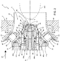
figure 2 is a schematic sectional view, with parts removed for greater clarity, of a burner unit according to the invention; -
figure 3 is a schematic view of a detail of the plant offigure 1 . - In
figure 1 , number 1 indicates an electrical power plant comprising agas turbine 2 extending along an axis A, acompressor 3, a combustor 4, afuel supply unit 6 configured to supply fuel to the combustor 4, and agenerator 7, which transforms the mechanical power provided by thegas turbine 2 into emitted electrical power. - The combustor 4 preferably is annular and comprises a plurality of
seats 8, each designed to be engaged by a burner unit 9 (which is better visible infigures 2-3 ). Theseats 8 are arranged along a circular path close to a peripheral edge of the combustor 4. In the non-limiting embodiment described and discussed herein, there are twenty-fourseats 8 andburner units 9. - With reference to
figure 2 , eachburner unit 9 extends along an axis B and comprises aninternal burner 10, anexternal burner 11, which extends around theinternal burner 10, and anintermediate burner 12, which is arranged between theexternal burner 11 and theinternal burner 10 around theinternal burner 10. - The
internal burner 10 extends along the axis B or extends around the axis B so as to create a hollow space that is left free so that it can house possible auxiliary devices. - In the non-limiting embodiment described and discussed herein, the
burner unit 9 further comprises anauxiliary device 14, which is arranged along the axis B, and theinternal burner 10 extends around theauxiliary device 14. - In the non-limiting embodiment described and discussed herein, the
auxiliary device 14 is supplied with air coming from thecompressor 3. Variants that are not shown herein involve the use of an auxiliary device provided with at least one additional supply for a secondary fuel, such as for example natural gas or Diesel fuel. Theinternal burner 10, theexternal burner 11 and theintermediate burner 12 are supplied by thefuel supply unit 6. - With reference to
figure 3 , thefuel supply unit 6 is configured so that theinternal burner 10, theexternal burner 11 and theintermediate burner 12 are supplied with fuel in an independent manner. In other words, the quantity of fuel supplied to theinternal burner 10 can be regulated independently of the quantity of fuel supplied to theexternal burner 11 and to theintermediate burner 12, and vice versa. - Preferably, the
fuel supply unit 6 comprises at least onefirst manifold 15, which is configured to supply fuel to the internal burners 10 (schematically shown infigure 3 ) of theburner units 9 of the combustor 4, asecond manifold 16, which is configured to supply fuel to the external burners 11 (schematically shown infigure 3 ) of theburner units 9 of the combustor 4, and athird manifold 17, which is configured to supply fuel to the intermediate burners 12 (schematically shown infigure 3 ) of theburner units 9 of the combustor 4. - The
first manifold 15, thesecond manifold 16 and thethird manifold 17 are connected to thesame tank 20 by means of respective supply lines provided withrespective regulating valves - By so doing, the quantity of fuel to be supplied to each manifold 15, 16, 17 can be regulated in an independent manner.
- Preferably, the regulating
valves - Preferably, the fuel in the
tank 20 is natural gas. - With reference to
figure 2 , theinternal burner 10, theexternal burner 11 and theintermediate burner 12 are supplied with air coming from thecompressor 3 and with fuel coming from thefuel supply unit 6. - The air and the fuel are supplied along a supply direction D1 directed towards the inside of the combustor 4.
- The
internal burner 10 comprises an internalair supply channel 24 and an internal fuel supply channel 25 (which is partially visible infigure 2 ). - The internal
air supply channel 24 is an annular channel extending around the axis B and around theauxiliary device 14 and is supplied with air coming from the exhaust of thecompressor 3. In particular, the internalair supply channel 24 is in communication with the inside of a case (not shown), which is supplied with air coming from thecompressor 3. - The internal
air supply channel 24 is sized so as to supply a given air flow rate. - Preferably, along the internal
air supply channel 24 there is arranged anauxiliary regulating device 24a, which is optional and is usually used to further regulate the flow rate flowing into theinternal burner 10. - In particular, the
auxiliary regulating device 24a is a narrowing of the passageway section of the internalair supply channel 24 and is defined by a ring coupled to the internal surface of the wall which defines the internalair supply channel 24 and is proximal to the axis B. - According to a variant that is not shown herein, the
auxiliary regulating device 24a is defined by a ring coupled to the internal surface of the wall which defines the internalair supply channel 24 and is distal relative to the axis B. - Along the internal
air supply channel 24 there is arranged aninternal swirler 26, which is provided with a plurality ofblades 27. - In the non-limiting embodiment described and discussed herein, the
internal swirler 26 is arranged at the outlet of the internalair supply channel 24. Preferably, theinternal swirler 26 is a diagonal swirler. - According to a variant that is not shown herein, the
internal swirler 26 is axial. - Here and below, by diagonal swirler we mean a swirler where the blades extend between walls which are shaped so as to define a channel that is substantially transverse to the axis B (annular channel substantially shaped like a truncated cone), whereas by axial swirler we mean a swirler where the blades extend between walls which are substantially shaped so as to define a channel that is parallel to the axis B (substantially cylindrical annular channel).
- The internal
fuel supply channel 25 is connected to the manifold 15 (which is not shown infigure 2 ) and is supplied with a given fuel flow rate QCI. - In detail, the internal
fuel supply channel 25 is an annular channel extending around the axis B and arranged between theauxiliary device 14 and the internalair supply channel 24 and is provided with a plurality of discharge nozzles 28 (only one of them can be seen infigure 2 ). - Preferably, the
discharge nozzles 28 are positioned so as to lead between the blades of theinternal swirler 26. - The
intermediate burner 12 comprises an intermediateair supply channel 30 and an intermediate fuel supply channel 31 (which is partially visible infigure 2 ). - The intermediate
air supply channel 30 is an annular channel extending around the axis B and around theinternal burner 10 and is supplied with air coming from the exhaust of thecompressor 3. In particular, the intermediateair supply channel 30 is in communication with the inside of a case (not shown), which is supplied with air coming from thecompressor 3. The intermediateair supply channel 30 is sized so as to supply a given air flow rate QAIn. - An
intermediate swirler 32 is arranged along the intermediateair supply channel 30. - Preferably, the
intermediate swirler 32 is a diagonal swirler provided with a plurality ofblades 33. In the non-limiting embodiment described and discussed herein, theintermediate swirler 32 is arranged close to the outlet of the intermediateair supply channel 30. - In particular, the outlet of the
intermediate swirler 32 is arranged upstream of the outlet of theinternal swirler 26 along the supply direction D1. According to a variant that is not shown herein, the outlet of theintermediate swirler 32 is substantially aligned with the outlet of theinternal swirler 26 along the supply direction D1. By "substantially aligned" we mean that the outlet of theintermediate swirler 32 and the outlet of theinternal swirler 26 are substantially aligned along a direction that is orthogonal to the axis B. - By "outlet of the swirler" we mean the outlet portion of the swirler that is axially located at the front along the supply direction D1.
- The intermediate
fuel supply channel 31 is connected to the manifold 17 and is supplied with a given fuel flow rate QCIn. - In detail, the intermediate
fuel supply channel 31 is an annular channel extending around the axis B and arranged between theinternal burner 10 and the intermediateair supply channel 30 and has a plurality ofdischarge nozzles 35 provided along at least someblades 33 of the swirler 32 (only somedischarge nozzles 35 can be seen infigure 2 ). - Preferably, the
discharge nozzles 35 are obtained along the leading edge of theblades 33. - The
intermediate swirler 32 is configured so as to help the mixing between the air and the fuel injected into the intermediateair supply channel 30 by thedischarge nozzles 35. Indeed, theintermediate swirler 32 is configured so to support the creation of vortexes that facilitate the mixing between air and fuel. - According to a variant that is not shown herein, the
intermediate swirler 32 is an axial swirler. - In the non-limiting embodiment described and discussed herein, the
intermediate swirler 32 and theinternal swirler 26 are co-rotating. In other words, theintermediate swirler 32 and theinternal swirler 26 are configured to cause the inflow to make a rotation in the same direction. - According to a further variant that is not shown herein, the
intermediate swirler 32 is counter-rotating relative to theinternal swirler 26. In other words, theintermediate swirler 32 and theinternal swirler 26 are configured to cause the inflow to make a rotation in two opposite directions. - Preferably, the
blades 33 of theintermediate swirler 32 are characterized by a blade airfoil that is optimized to as have a uniform profile of the axial velocity of the flow and avoid sudden accelerations or decelerations of the flow itself. - Preferably, the
blades 33 of theintermediate swirler 32 are characterized by the following aerodynamic parameters: - trailing angle ranging between 55° and 70°; in this way, the interaction between the flow flowing out of the intermediate swirler and the flow flowing out of the
internal swirler 26 is optimized for the purpose of controlling, as discussed more in detail hereinafter, the shape of the flame internal recirculation zone (IRZ); by "trailing angle", here and below, we mean the angle defined between the prolongation of the middle line of the blade (usually defined camber line) and a direction parallel to the axis B; - minimum axial velocity of the flow at the trailing edge of the
blades 33 equal to approximately 60 m/s; in this way, the axial velocity of the flow is high enough to avoid flame flashbacks;- pressure drop ≥ 117 kPa; in this way, the desired flow separation is obtained so as to reach the desired air flow rate in the
intermediate swirler 32; - number of blades ranging between 6 and 12; in this way, the distribution of the fuel injected in the area of the
swirler 32 can be regulated as best as possible.
- pressure drop ≥ 117 kPa; in this way, the desired flow separation is obtained so as to reach the desired air flow rate in the
- The
external burner 11 comprises an intermediateair supply channel 40 as well as a main externalfuel supply channel 41a (which is partially visible infigure 2 ) and a secondary externalfuel supply channel 41b. - The external
air supply channel 40 is an annular channel provided with anaxial portion 42, which extends around the axis B, and aninclined portion 43, which extends along a direction that is inclined relative to the axis B. - The
inclined portion 43 is in communication with the inside of a case (not shown), which is supplied with air coming from thecompressor 3. Theaxial portion 42 leads into the combustor 4 and preferably is coupled to a cylindrical outlet element 44 (generally defined CBO). - The external
air supply channel 40 is sized so as to supply a given air flow rate QAE. - The external
air supply channel 40 is provided with anexternal swirler 45. - In the non-limiting embodiment described and discussed herein, the
external swirler 45 is arranged along theinclined portion 43. - Preferably, the
external swirler 45 is a diagonal swirler provided with a plurality ofblades 46. - In particular, the outlet of the
external swirler 45 is arranged upstream of outlet of theintermediate swirler 32 and of the outlet of theinternal swirler 26 along the supply direction D1. - Again, by "outlet of the swirler" we mean the outlet portion of the swirler that is axially located at the front along the supply direction D1.
- The main external
fuel supply channel 41a is connected to the manifold 16 and is supplied with a given fuel flow rate QCEp. - In detail, the main external
fuel supply channel 41a is an annular channel extending around the axis B and arranged between theintermediate burner 12 and the externalair supply channel 40 and is provided with a plurality of discharge nozzles 47 (only one of them are visible infigure 2 ), which are obtained along at least someblades 46 of theswirler 45. - Preferably, the
discharge nozzles 47 are obtained along the leading edge of theblades 46. - The secondary external
fuel supply channel 41b is optional and is connected to a secondary manifold (also optional), which is not shown infigure 3 . The secondary externalfuel supply channel 41b is supplied with a given fuel flow rate QCEs. - In detail, the secondary external
fuel supply channel 41b is an annular channel extending around the axis B and arranged between theintermediate burner 12 and the main externalfuel supply channel 41a and has a plurality of discharge nozzles 48 (only some of them are visible infigure 2 ), which are provided along the wall of the externalair supply channel 40 substantially at the trailing edge of theblades 46 of theswirler 45. - The
external swirler 45 is configured so as to help the mixing between the air and the fuel injected into the externalair supply channel 40 by thedischarge nozzles 47 and by thedischarge nozzles 48. Indeed, theexternal swirler 45 is configured to support the creation of vortexes that facilitate the mixing between air and fuel. - The three flows of air-fuel mixture, which were properly mixed in the
internal burner 10, in theexternal burner 11 and in theintermediate burner 12, flow into one single fluid volume, which is substantially arranged in front of the outlet of theinternal burner 10 in the supply direction D1 and is delimited by theaxial portion 42 and by thecylindrical outlet element 44 of theexternal burner 11, thus generating one single flame front. In particular, the offset position of theexternal swirler 45, of theintermediate swirler 32 and of the internal swirler 26 (the outlet of theexternal swirler 45 being arranged upstream of the outlet of theintermediate swirler 32 and the outlet of theintermediate swirler 32 being arranged upstream of the outlet of theinternal swirler 26 or aligned with the outlet of the internal swirler 26) supports the generation of one single combustion zone, where the shape of the inner recirculation zone (IRZ) is well defined, so as to reduce the creation of precessing vortex cores (PVC). - This configuration permits a regulation of the shape of the flame front and, especially, of the IRZ.
- Indeed, the possibility of independently defining three different air-fuel ratios in the
internal burner 10, in theexternal burner 11 and in theintermediate burner 12 affects the shape of the flame front and of the IRZ. - The shape of the IRZ can be substantially represented like a parabola having a vertex V arranged along the axis B and a concavity facing the inside of the combustor 4.
- The
intermediate swirler 32 and theinternal swirler 26 create two flows, whose vortex component is substantially different and, in addition, can be regulated by means of a controlled and differentiated supply of theinternal burner 10 and of theintermediate burner 12. - The presence of different vortex components on distinct radial coordinates actually allows to force the shape of the IRZ until the desired shape is obtained, which minimizes the generation of precessing vortex cores. In the non-limiting embodiment described and discussed herein, the parabola, which schematically defines the shape of the inner recirculation zone - IRZ, is characterized by a widening in a direction that is orthogonal to the axis B, which definitely is already significant in the proximity of the vertex V of the parabola. In this way, a "flattened" shape of the IRZ is obtained, which positively affects the PVC (precessing vortex core) and, as a consequence, determines an improvement of flame stability.
- In detail, if the fluid-dynamic profile of the inner recirculation zone IRZ) is more "flattened", the PVC is more chaotic in its periodic motion and, as a consequence, the flame is more stable.
- Furthermore, thanks to this solution, the periodic motion of the PVC is prevented from affecting the mixing of the gas in the different areas of interest. This avoids the occurrence of a gas mixing variation phenomenon, which is also periodic and associated with the motion of the PVC itself.
- Thanks to the presence of the intermediate swirler there is an increase in the degree of air/fuel mixing, which is necessary for the reduction of polluting emissions. Furthermore, thanks to the possibility of independently supplying the
internal burner 10, theexternal burner 11 and theintermediate burner 12, a gradual mixing profile can be created, which helps generate a more stable flame. - Indeed, the degree of mixing can be modulated in the
internal swirler 28, in theintermediate swirler 32 and in theexternal swirler 45, though keeping the power of theburner unit 9, as a whole, constant. By so doing, areas with different values of the air/fuel ratio can be obtained in the combustion zone. - For example, the supply of fuel to the
internal swirler 28 can be regulated so that the air/fuel ratio is smaller than the air/fuel ratios of theintermediate swirler 32 and of theexternal swirler 45. In this way, a "micro-pilot" flame is obtained in the area of the axis B, which helps increase the stability of the combustion without drastically worsening the quantity of polluting emissions. - Finally, it is clear that the burner unit, the plant and the method described herein can be subject to changes and variations, without for this reason going beyond the scope of protection set forth in the appended claims.
Claims (14)
- A burner unit for a combustor (4) of a gas turbine electrical power plant; the burner unit (9) extends around a longitudinal axis (B) and comprises:• an internal burner (10) supplied with air and fuel, which extends around the longitudinal axis (B) and is provided with at least one internal swirler (28);• an external burner (11) supplied with air and fuel, which extends around the internal burner (10) and is provided with at least one external swirler (45);• an intermediate burner (12) supplied with air and fuel, which is arranged between the external burner (11) and the internal burner (10) around the internal burner (10) and is provided with an intermediate swirler (32);• the outlet of the intermediate swirler (32) being arranged upstream of the outlet of the internal swirler (26) or aligned with the outlet of the internal swirler (26) in the supply direction (D1) of the air and the fuel directed towards the inside of the combustor (4).
- The burner unit according to claim 1, wherein the outlet of the external swirler (45) is arranged upstream of the outlet of the intermediate swirler (32).
- The burner unit according to claim 2, wherein the fuel is natural gas.
- The burner unit according to any one of the preceding claims, wherein the intermediate swirler (32) is provided with a plurality of blades (33).
- The burner unit according to claim 4, wherein the blades (33) have an trailing angle ranging between 55° and 70°.
- The burner unit according to claim 4 or 5, wherein the minimum axial velocity of the flow at the outlet of the blades (33) is approximately equal to 60 m/s.
- The burner unit according to any one of the claims from 4 to 6, wherein the pressure drop at the intermediate swirler (32) is less than or equal to 117 kPa.
- The burner unit according to any one of the claims from 4 to 7, wherein the intermediate swirler (32) comprises a number of blades (33) ranging between 6 and 12.
- A gas turbine electrical power plant comprising a combustor (4) provided with at least one burner unit (9) as claimed in any one of the preceding claims.
- The plant according to claim 9, comprising a fuel supply unit (6) provided with at least one first manifold (15) configured to supply fuel to the internal burner (10) of at least one burner unit (9) of the combustor (4), a second manifold (16) configured to supply fuel to the external burner (11) of at least one burner unit (9) of the combustor (4), and a third manifold (17) configured to supply fuel to the intermediate burner (12) of at least one burner unit (9) of the combustor (4).
- The plant according to claim 10, wherein the first manifold (15), the second manifold (16) and the third manifold (17) are connected to the same tank (20) by respective supply lines provided with respective regulating valves (21a, 21b, 21c).
- A method for operating a gas turbine electrical power plant; the plant (1) comprising a compressor (3), a gas turbine (2) and a combustor (4) provided with a least one burner unit (9); the burner unit (9) comprising:• an internal burner (10) supplied with air coming from the exhaust of the compressor (3) and provided with at least one internal swirler (28);• an external burner (11) supplied with air coming from the exhaust of the compressor (3) and provided with at least one external swirler (45);• an intermediate burner (12) supplied with air coming from the exhaust of the compressor (3) and provided with one intermediate swirler (32);the method comprising supplying fuel to the internal burner (10), to the external burner (11) and to the intermediate burner (12) in an independent manner.
- The method according to claim 12, wherein the step of supplying fuel to the internal burner (10), to the external burner (11) and to the intermediate burner (12) in an independent manner comprises regulating the quantity of fuel supplied to a first manifold (15), to a second manifold (16) and to a third manifold (17), respectively configured to supply fuel to at least one internal burner (10), to at least one external burner (11) and to at least one intermediate burner (12).
- The method according to claim 12 or 13, wherein the step of supplying fuel to the internal burner (10), to the external burner (11) and to the intermediate burner (12) in an independent manner comprises regulating the fuel supply to the internal burner (10) so that the air/fuel ratio is lower than the air/fuel ratios of the intermediate burner (12) and of the external burner (11).
Applications Claiming Priority (1)
| Application Number | Priority Date | Filing Date | Title |
|---|---|---|---|
| IT102017000027637A IT201700027637A1 (en) | 2017-03-13 | 2017-03-13 | BURNER UNIT FOR A GAS TURBINE SYSTEM FOR THE PRODUCTION OF ELECTRICITY, GAS TURBINE PLANT FOR THE PRODUCTION OF ELECTRIC ENERGY INCLUDING THE BURNER GROUP AND METHOD TO OPERATE THE GAS TURBINE SYSTEM |
Publications (2)
| Publication Number | Publication Date |
|---|---|
| EP3376110A1 true EP3376110A1 (en) | 2018-09-19 |
| EP3376110B1 EP3376110B1 (en) | 2022-07-20 |
Family
ID=59409690
Family Applications (1)
| Application Number | Title | Priority Date | Filing Date |
|---|---|---|---|
| EP18161522.0A Active EP3376110B1 (en) | 2017-03-13 | 2018-03-13 | Gas turbine electrical power plant and method for operating said gas turbine electrical power plant |
Country Status (3)
| Country | Link |
|---|---|
| EP (1) | EP3376110B1 (en) |
| CN (2) | CN120212538A (en) |
| IT (1) | IT201700027637A1 (en) |
Citations (5)
| Publication number | Priority date | Publication date | Assignee | Title |
|---|---|---|---|---|
| RU2050511C1 (en) * | 1993-05-19 | 1995-12-20 | Научно-технологический центр энергосберегающих процессов и установок | Method for burning organic fuel |
| JP2005283003A (en) * | 2004-03-30 | 2005-10-13 | Osaka Gas Co Ltd | Combustion device and gas turbine engine |
| EP1596132A1 (en) * | 2004-05-11 | 2005-11-16 | United Technologies Corporation | Nozzle |
| EP1909032A2 (en) * | 2006-10-05 | 2008-04-09 | General Electric Company | Method and apparatus for reducing gas turbine engine emissions |
| US20090056336A1 (en) * | 2007-08-28 | 2009-03-05 | General Electric Company | Gas turbine premixer with radially staged flow passages and method for mixing air and gas in a gas turbine |
Family Cites Families (3)
| Publication number | Priority date | Publication date | Assignee | Title |
|---|---|---|---|---|
| KR101049359B1 (en) * | 2008-10-31 | 2011-07-13 | 한국전력공사 | Triple swirl gas turbine combustor |
| CN102242940B (en) * | 2011-07-29 | 2014-02-12 | 北京航空航天大学 | A low-pollution combustor with three-stage premixed and preevaporated structure |
| CN202675358U (en) * | 2012-07-11 | 2013-01-16 | 中航商用航空发动机有限责任公司 | Mixing device, combustion chamber and aeroengine |
-
2017
- 2017-03-13 IT IT102017000027637A patent/IT201700027637A1/en unknown
-
2018
- 2018-03-13 CN CN202510489383.1A patent/CN120212538A/en active Pending
- 2018-03-13 EP EP18161522.0A patent/EP3376110B1/en active Active
- 2018-03-13 CN CN201810204250.5A patent/CN108571747A/en active Pending
Patent Citations (5)
| Publication number | Priority date | Publication date | Assignee | Title |
|---|---|---|---|---|
| RU2050511C1 (en) * | 1993-05-19 | 1995-12-20 | Научно-технологический центр энергосберегающих процессов и установок | Method for burning organic fuel |
| JP2005283003A (en) * | 2004-03-30 | 2005-10-13 | Osaka Gas Co Ltd | Combustion device and gas turbine engine |
| EP1596132A1 (en) * | 2004-05-11 | 2005-11-16 | United Technologies Corporation | Nozzle |
| EP1909032A2 (en) * | 2006-10-05 | 2008-04-09 | General Electric Company | Method and apparatus for reducing gas turbine engine emissions |
| US20090056336A1 (en) * | 2007-08-28 | 2009-03-05 | General Electric Company | Gas turbine premixer with radially staged flow passages and method for mixing air and gas in a gas turbine |
Also Published As
| Publication number | Publication date |
|---|---|
| CN120212538A (en) | 2025-06-27 |
| CN108571747A (en) | 2018-09-25 |
| EP3376110B1 (en) | 2022-07-20 |
| IT201700027637A1 (en) | 2018-09-13 |
Similar Documents
| Publication | Publication Date | Title |
|---|---|---|
| JP6159136B2 (en) | System and method having a multi-tube fuel nozzle with differential flow | |
| EP3320268B1 (en) | Burner for a gas turbine and method for operating the burner | |
| US6962055B2 (en) | Multi-point staging strategy for low emission and stable combustion | |
| EP2904326B1 (en) | Flamesheet combustor dome | |
| EP2065645B1 (en) | Burner and gas turbine combustor | |
| US9518740B2 (en) | Axial swirler for a gas turbine burner | |
| EP4278132B1 (en) | Burner | |
| EP2578941A2 (en) | System for Fuel Injection in a Fuel Nozzle | |
| US20140096502A1 (en) | Burner for a gas turbine | |
| US20090056336A1 (en) | Gas turbine premixer with radially staged flow passages and method for mixing air and gas in a gas turbine | |
| KR20120092111A (en) | Vortex premixer for combustion apparatus | |
| US10288291B2 (en) | Air-shielded fuel injection assembly to facilitate reduced NOx emissions in a combustor system | |
| EP1826485A2 (en) | Burner, method of combustion with the burner, and method of modifying the burner | |
| EP2873922A1 (en) | Gas turbine combustor | |
| JPH08135970A (en) | Gas turbine combustor | |
| CA3010044C (en) | Combustor for a gas turbine | |
| EP2948715B1 (en) | Burner system having turbulence elements | |
| US20210116127A1 (en) | Gas Turbine Combuster | |
| EP3376110B1 (en) | Gas turbine electrical power plant and method for operating said gas turbine electrical power plant | |
| US20250067436A1 (en) | Ammonia combustor | |
| EP1531305A1 (en) | Multi-point fuel injector | |
| EP3667168B1 (en) | Injection system with radial in-flow swirl premix gas fuel injectors | |
| US20250067212A1 (en) | Alternative fuel combustor with recirculation zone | |
| JP2008082590A (en) | Gas turbine combustor |
Legal Events
| Date | Code | Title | Description |
|---|---|---|---|
| PUAI | Public reference made under article 153(3) epc to a published international application that has entered the european phase |
Free format text: ORIGINAL CODE: 0009012 |
|
| STAA | Information on the status of an ep patent application or granted ep patent |
Free format text: STATUS: THE APPLICATION HAS BEEN PUBLISHED |
|
| AK | Designated contracting states |
Kind code of ref document: A1 Designated state(s): AL AT BE BG CH CY CZ DE DK EE ES FI FR GB GR HR HU IE IS IT LI LT LU LV MC MK MT NL NO PL PT RO RS SE SI SK SM TR |
|
| AX | Request for extension of the european patent |
Extension state: BA ME |
|
| STAA | Information on the status of an ep patent application or granted ep patent |
Free format text: STATUS: REQUEST FOR EXAMINATION WAS MADE |
|
| 17P | Request for examination filed |
Effective date: 20190318 |
|
| RBV | Designated contracting states (corrected) |
Designated state(s): AL AT BE BG CH CY CZ DE DK EE ES FI FR GB GR HR HU IE IS IT LI LT LU LV MC MK MT NL NO PL PT RO RS SE SI SK SM TR |
|
| STAA | Information on the status of an ep patent application or granted ep patent |
Free format text: STATUS: EXAMINATION IS IN PROGRESS |
|
| 17Q | First examination report despatched |
Effective date: 20200305 |
|
| GRAP | Despatch of communication of intention to grant a patent |
Free format text: ORIGINAL CODE: EPIDOSNIGR1 |
|
| STAA | Information on the status of an ep patent application or granted ep patent |
Free format text: STATUS: GRANT OF PATENT IS INTENDED |
|
| INTG | Intention to grant announced |
Effective date: 20220209 |
|
| GRAS | Grant fee paid |
Free format text: ORIGINAL CODE: EPIDOSNIGR3 |
|
| GRAA | (expected) grant |
Free format text: ORIGINAL CODE: 0009210 |
|
| STAA | Information on the status of an ep patent application or granted ep patent |
Free format text: STATUS: THE PATENT HAS BEEN GRANTED |
|
| AK | Designated contracting states |
Kind code of ref document: B1 Designated state(s): AL AT BE BG CH CY CZ DE DK EE ES FI FR GB GR HR HU IE IS IT LI LT LU LV MC MK MT NL NO PL PT RO RS SE SI SK SM TR |
|
| REG | Reference to a national code |
Ref country code: CH Ref legal event code: EP |
|
| REG | Reference to a national code |
Ref country code: DE Ref legal event code: R096 Ref document number: 602018038033 Country of ref document: DE |
|
| REG | Reference to a national code |
Ref country code: AT Ref legal event code: REF Ref document number: 1505740 Country of ref document: AT Kind code of ref document: T Effective date: 20220815 |
|
| REG | Reference to a national code |
Ref country code: IE Ref legal event code: FG4D |
|
| REG | Reference to a national code |
Ref country code: LT Ref legal event code: MG9D |
|
| REG | Reference to a national code |
Ref country code: NL Ref legal event code: MP Effective date: 20220720 |
|
| PG25 | Lapsed in a contracting state [announced via postgrant information from national office to epo] |
Ref country code: SE Free format text: LAPSE BECAUSE OF FAILURE TO SUBMIT A TRANSLATION OF THE DESCRIPTION OR TO PAY THE FEE WITHIN THE PRESCRIBED TIME-LIMIT Effective date: 20220720 Ref country code: RS Free format text: LAPSE BECAUSE OF FAILURE TO SUBMIT A TRANSLATION OF THE DESCRIPTION OR TO PAY THE FEE WITHIN THE PRESCRIBED TIME-LIMIT Effective date: 20220720 Ref country code: PT Free format text: LAPSE BECAUSE OF FAILURE TO SUBMIT A TRANSLATION OF THE DESCRIPTION OR TO PAY THE FEE WITHIN THE PRESCRIBED TIME-LIMIT Effective date: 20221121 Ref country code: NO Free format text: LAPSE BECAUSE OF FAILURE TO SUBMIT A TRANSLATION OF THE DESCRIPTION OR TO PAY THE FEE WITHIN THE PRESCRIBED TIME-LIMIT Effective date: 20221020 Ref country code: NL Free format text: LAPSE BECAUSE OF FAILURE TO SUBMIT A TRANSLATION OF THE DESCRIPTION OR TO PAY THE FEE WITHIN THE PRESCRIBED TIME-LIMIT Effective date: 20220720 Ref country code: LV Free format text: LAPSE BECAUSE OF FAILURE TO SUBMIT A TRANSLATION OF THE DESCRIPTION OR TO PAY THE FEE WITHIN THE PRESCRIBED TIME-LIMIT Effective date: 20220720 Ref country code: LT Free format text: LAPSE BECAUSE OF FAILURE TO SUBMIT A TRANSLATION OF THE DESCRIPTION OR TO PAY THE FEE WITHIN THE PRESCRIBED TIME-LIMIT Effective date: 20220720 Ref country code: FI Free format text: LAPSE BECAUSE OF FAILURE TO SUBMIT A TRANSLATION OF THE DESCRIPTION OR TO PAY THE FEE WITHIN THE PRESCRIBED TIME-LIMIT Effective date: 20220720 Ref country code: ES Free format text: LAPSE BECAUSE OF FAILURE TO SUBMIT A TRANSLATION OF THE DESCRIPTION OR TO PAY THE FEE WITHIN THE PRESCRIBED TIME-LIMIT Effective date: 20220720 |
|
| REG | Reference to a national code |
Ref country code: AT Ref legal event code: MK05 Ref document number: 1505740 Country of ref document: AT Kind code of ref document: T Effective date: 20220720 |
|
| PG25 | Lapsed in a contracting state [announced via postgrant information from national office to epo] |
Ref country code: PL Free format text: LAPSE BECAUSE OF FAILURE TO SUBMIT A TRANSLATION OF THE DESCRIPTION OR TO PAY THE FEE WITHIN THE PRESCRIBED TIME-LIMIT Effective date: 20220720 Ref country code: IS Free format text: LAPSE BECAUSE OF FAILURE TO SUBMIT A TRANSLATION OF THE DESCRIPTION OR TO PAY THE FEE WITHIN THE PRESCRIBED TIME-LIMIT Effective date: 20221120 Ref country code: HR Free format text: LAPSE BECAUSE OF FAILURE TO SUBMIT A TRANSLATION OF THE DESCRIPTION OR TO PAY THE FEE WITHIN THE PRESCRIBED TIME-LIMIT Effective date: 20220720 Ref country code: GR Free format text: LAPSE BECAUSE OF FAILURE TO SUBMIT A TRANSLATION OF THE DESCRIPTION OR TO PAY THE FEE WITHIN THE PRESCRIBED TIME-LIMIT Effective date: 20221021 |
|
| REG | Reference to a national code |
Ref country code: DE Ref legal event code: R097 Ref document number: 602018038033 Country of ref document: DE |
|
| PG25 | Lapsed in a contracting state [announced via postgrant information from national office to epo] |
Ref country code: SM Free format text: LAPSE BECAUSE OF FAILURE TO SUBMIT A TRANSLATION OF THE DESCRIPTION OR TO PAY THE FEE WITHIN THE PRESCRIBED TIME-LIMIT Effective date: 20220720 Ref country code: RO Free format text: LAPSE BECAUSE OF FAILURE TO SUBMIT A TRANSLATION OF THE DESCRIPTION OR TO PAY THE FEE WITHIN THE PRESCRIBED TIME-LIMIT Effective date: 20220720 Ref country code: DK Free format text: LAPSE BECAUSE OF FAILURE TO SUBMIT A TRANSLATION OF THE DESCRIPTION OR TO PAY THE FEE WITHIN THE PRESCRIBED TIME-LIMIT Effective date: 20220720 Ref country code: CZ Free format text: LAPSE BECAUSE OF FAILURE TO SUBMIT A TRANSLATION OF THE DESCRIPTION OR TO PAY THE FEE WITHIN THE PRESCRIBED TIME-LIMIT Effective date: 20220720 Ref country code: AT Free format text: LAPSE BECAUSE OF FAILURE TO SUBMIT A TRANSLATION OF THE DESCRIPTION OR TO PAY THE FEE WITHIN THE PRESCRIBED TIME-LIMIT Effective date: 20220720 |
|
| PLBE | No opposition filed within time limit |
Free format text: ORIGINAL CODE: 0009261 |
|
| STAA | Information on the status of an ep patent application or granted ep patent |
Free format text: STATUS: NO OPPOSITION FILED WITHIN TIME LIMIT |
|
| PG25 | Lapsed in a contracting state [announced via postgrant information from national office to epo] |
Ref country code: SK Free format text: LAPSE BECAUSE OF FAILURE TO SUBMIT A TRANSLATION OF THE DESCRIPTION OR TO PAY THE FEE WITHIN THE PRESCRIBED TIME-LIMIT Effective date: 20220720 Ref country code: EE Free format text: LAPSE BECAUSE OF FAILURE TO SUBMIT A TRANSLATION OF THE DESCRIPTION OR TO PAY THE FEE WITHIN THE PRESCRIBED TIME-LIMIT Effective date: 20220720 |
|
| 26N | No opposition filed |
Effective date: 20230421 |
|
| PG25 | Lapsed in a contracting state [announced via postgrant information from national office to epo] |
Ref country code: AL Free format text: LAPSE BECAUSE OF FAILURE TO SUBMIT A TRANSLATION OF THE DESCRIPTION OR TO PAY THE FEE WITHIN THE PRESCRIBED TIME-LIMIT Effective date: 20220720 |
|
| PG25 | Lapsed in a contracting state [announced via postgrant information from national office to epo] |
Ref country code: SI Free format text: LAPSE BECAUSE OF FAILURE TO SUBMIT A TRANSLATION OF THE DESCRIPTION OR TO PAY THE FEE WITHIN THE PRESCRIBED TIME-LIMIT Effective date: 20220720 |
|
| PG25 | Lapsed in a contracting state [announced via postgrant information from national office to epo] |
Ref country code: MC Free format text: LAPSE BECAUSE OF FAILURE TO SUBMIT A TRANSLATION OF THE DESCRIPTION OR TO PAY THE FEE WITHIN THE PRESCRIBED TIME-LIMIT Effective date: 20220720 |
|
| REG | Reference to a national code |
Ref country code: CH Ref legal event code: PL |
|
| GBPC | Gb: european patent ceased through non-payment of renewal fee |
Effective date: 20230313 |
|
| REG | Reference to a national code |
Ref country code: BE Ref legal event code: MM Effective date: 20230331 |
|
| PG25 | Lapsed in a contracting state [announced via postgrant information from national office to epo] |
Ref country code: LU Free format text: LAPSE BECAUSE OF NON-PAYMENT OF DUE FEES Effective date: 20230313 |
|
| REG | Reference to a national code |
Ref country code: IE Ref legal event code: MM4A |
|
| PG25 | Lapsed in a contracting state [announced via postgrant information from national office to epo] |
Ref country code: GB Free format text: LAPSE BECAUSE OF NON-PAYMENT OF DUE FEES Effective date: 20230313 |
|
| PG25 | Lapsed in a contracting state [announced via postgrant information from national office to epo] |
Ref country code: LI Free format text: LAPSE BECAUSE OF NON-PAYMENT OF DUE FEES Effective date: 20230331 Ref country code: IE Free format text: LAPSE BECAUSE OF NON-PAYMENT OF DUE FEES Effective date: 20230313 Ref country code: GB Free format text: LAPSE BECAUSE OF NON-PAYMENT OF DUE FEES Effective date: 20230313 Ref country code: FR Free format text: LAPSE BECAUSE OF NON-PAYMENT OF DUE FEES Effective date: 20230331 Ref country code: CH Free format text: LAPSE BECAUSE OF NON-PAYMENT OF DUE FEES Effective date: 20230331 |
|
| PG25 | Lapsed in a contracting state [announced via postgrant information from national office to epo] |
Ref country code: BE Free format text: LAPSE BECAUSE OF NON-PAYMENT OF DUE FEES Effective date: 20230331 |
|
| PG25 | Lapsed in a contracting state [announced via postgrant information from national office to epo] |
Ref country code: IT Free format text: LAPSE BECAUSE OF FAILURE TO SUBMIT A TRANSLATION OF THE DESCRIPTION OR TO PAY THE FEE WITHIN THE PRESCRIBED TIME-LIMIT Effective date: 20220720 |
|
| P01 | Opt-out of the competence of the unified patent court (upc) registered |
Effective date: 20240430 |
|
| PG25 | Lapsed in a contracting state [announced via postgrant information from national office to epo] |
Ref country code: BG Free format text: LAPSE BECAUSE OF FAILURE TO SUBMIT A TRANSLATION OF THE DESCRIPTION OR TO PAY THE FEE WITHIN THE PRESCRIBED TIME-LIMIT Effective date: 20220720 |
|
| PG25 | Lapsed in a contracting state [announced via postgrant information from national office to epo] |
Ref country code: BG Free format text: LAPSE BECAUSE OF FAILURE TO SUBMIT A TRANSLATION OF THE DESCRIPTION OR TO PAY THE FEE WITHIN THE PRESCRIBED TIME-LIMIT Effective date: 20220720 |
|
| PG25 | Lapsed in a contracting state [announced via postgrant information from national office to epo] |
Ref country code: CY Free format text: LAPSE BECAUSE OF FAILURE TO SUBMIT A TRANSLATION OF THE DESCRIPTION OR TO PAY THE FEE WITHIN THE PRESCRIBED TIME-LIMIT; INVALID AB INITIO Effective date: 20180313 |
|
| PG25 | Lapsed in a contracting state [announced via postgrant information from national office to epo] |
Ref country code: HU Free format text: LAPSE BECAUSE OF FAILURE TO SUBMIT A TRANSLATION OF THE DESCRIPTION OR TO PAY THE FEE WITHIN THE PRESCRIBED TIME-LIMIT; INVALID AB INITIO Effective date: 20180313 |
|
| PG25 | Lapsed in a contracting state [announced via postgrant information from national office to epo] |
Ref country code: TR Free format text: LAPSE BECAUSE OF FAILURE TO SUBMIT A TRANSLATION OF THE DESCRIPTION OR TO PAY THE FEE WITHIN THE PRESCRIBED TIME-LIMIT Effective date: 20220720 |
|
| PGFP | Annual fee paid to national office [announced via postgrant information from national office to epo] |
Ref country code: DE Payment date: 20260320 Year of fee payment: 9 |
|
| PG25 | Lapsed in a contracting state [announced via postgrant information from national office to epo] |
Ref country code: MT Free format text: LAPSE BECAUSE OF NON-PAYMENT OF DUE FEES Effective date: 20230313 |