EP3375999A1 - Turbocharger - Google Patents
Turbocharger Download PDFInfo
- Publication number
- EP3375999A1 EP3375999A1 EP18161071.8A EP18161071A EP3375999A1 EP 3375999 A1 EP3375999 A1 EP 3375999A1 EP 18161071 A EP18161071 A EP 18161071A EP 3375999 A1 EP3375999 A1 EP 3375999A1
- Authority
- EP
- European Patent Office
- Prior art keywords
- rotating shaft
- extension portion
- valve
- valve body
- drive arm
- Prior art date
- Legal status (The legal status is an assumption and is not a legal conclusion. Google has not performed a legal analysis and makes no representation as to the accuracy of the status listed.)
- Granted
Links
Images


Classifications
-
- F—MECHANICAL ENGINEERING; LIGHTING; HEATING; WEAPONS; BLASTING
- F02—COMBUSTION ENGINES; HOT-GAS OR COMBUSTION-PRODUCT ENGINE PLANTS
- F02B—INTERNAL-COMBUSTION PISTON ENGINES; COMBUSTION ENGINES IN GENERAL
- F02B37/00—Engines characterised by provision of pumps driven at least for part of the time by exhaust
- F02B37/12—Control of the pumps
- F02B37/18—Control of the pumps by bypassing exhaust from the inlet to the outlet of turbine or to the atmosphere
- F02B37/183—Arrangements of bypass valves or actuators therefor
- F02B37/186—Arrangements of actuators or linkage for bypass valves
-
- F—MECHANICAL ENGINEERING; LIGHTING; HEATING; WEAPONS; BLASTING
- F02—COMBUSTION ENGINES; HOT-GAS OR COMBUSTION-PRODUCT ENGINE PLANTS
- F02B—INTERNAL-COMBUSTION PISTON ENGINES; COMBUSTION ENGINES IN GENERAL
- F02B37/00—Engines characterised by provision of pumps driven at least for part of the time by exhaust
- F02B37/12—Control of the pumps
- F02B37/18—Control of the pumps by bypassing exhaust from the inlet to the outlet of turbine or to the atmosphere
-
- F—MECHANICAL ENGINEERING; LIGHTING; HEATING; WEAPONS; BLASTING
- F02—COMBUSTION ENGINES; HOT-GAS OR COMBUSTION-PRODUCT ENGINE PLANTS
- F02M—SUPPLYING COMBUSTION ENGINES IN GENERAL WITH COMBUSTIBLE MIXTURES OR CONSTITUENTS THEREOF
- F02M26/00—Engine-pertinent apparatus for adding exhaust gases to combustion-air, main fuel or fuel-air mixture, e.g. by exhaust gas recirculation [EGR] systems
- F02M26/52—Systems for actuating EGR valves
- F02M26/53—Systems for actuating EGR valves using electric actuators, e.g. solenoids
-
- F—MECHANICAL ENGINEERING; LIGHTING; HEATING; WEAPONS; BLASTING
- F02—COMBUSTION ENGINES; HOT-GAS OR COMBUSTION-PRODUCT ENGINE PLANTS
- F02M—SUPPLYING COMBUSTION ENGINES IN GENERAL WITH COMBUSTIBLE MIXTURES OR CONSTITUENTS THEREOF
- F02M26/00—Engine-pertinent apparatus for adding exhaust gases to combustion-air, main fuel or fuel-air mixture, e.g. by exhaust gas recirculation [EGR] systems
- F02M26/65—Constructional details of EGR valves
- F02M26/66—Lift valves, e.g. poppet valves
- F02M26/67—Pintles; Spindles; Springs; Bearings; Sealings; Connections to actuators
-
- Y—GENERAL TAGGING OF NEW TECHNOLOGICAL DEVELOPMENTS; GENERAL TAGGING OF CROSS-SECTIONAL TECHNOLOGIES SPANNING OVER SEVERAL SECTIONS OF THE IPC; TECHNICAL SUBJECTS COVERED BY FORMER USPC CROSS-REFERENCE ART COLLECTIONS [XRACs] AND DIGESTS
- Y02—TECHNOLOGIES OR APPLICATIONS FOR MITIGATION OR ADAPTATION AGAINST CLIMATE CHANGE
- Y02T—CLIMATE CHANGE MITIGATION TECHNOLOGIES RELATED TO TRANSPORTATION
- Y02T10/00—Road transport of goods or passengers
- Y02T10/10—Internal combustion engine [ICE] based vehicles
- Y02T10/12—Improving ICE efficiencies
Definitions
- the present invention relates to a turbocharger including a wastegate valve device.
- a wastegate valve device for the turbocharger includes a valve body configured to open and close the wastegate port, a rotating shaft inserted through an insertion hole formed on a side wall of the turbine housing, and a swing arm fixed to the rotating shaft.
- the swing arm supports the valve body at a position distanced from a part fixed to the rotating shaft in the radial direction of the rotating shaft. Accordingly, the valve body is configured to open and close the wastegate port such that the rotating shaft and the swing arm rotate around the rotating shaft as the axial center.
- valve body when the rotating shaft and the swing arm are rotated in a first direction, the valve body can approach the wastegate port, and when the rotating shaft and the swing arm are rotated in a second direction that is a reverse direction with respect to the first direction, the valve body can be distanced from the wastegate port.
- the wastegate valve device is provided with a drive arm placed outside the turbine housing and fixed to the rotating shaft, and a rod rotatably connected to the drive arm. More specifically, the rod is rotatably connected to the drive arm at a position distanced from a part fixed to the rotating shaft in the radial direction of the rotating shaft.
- the drive arm, the rotating shaft, and the swing arm are rotated in the second direction, so that the valve body is distanced from the wastegate port.
- the exhaust gas flowing into the turbine wheel passes through the wastegate port.
- the valve body is placed on the downstream side from the wastegate port in the turbine housing. Accordingly, when the valve body is distanced from the wastegate port, the exhaust gas passing through the wastegate port interferes with the valve body. That is, the valve body receives a load corresponding to the pressure of the exhaust gas. At this time, when a load to be received by the valve body fluctuates due to pulsation of the pressure of the exhaust gas that interferes with the valve body, the rotating shaft connected to the valve body via the swing arm vibrates. As a result, an abnormal noise might occur due to the rotating shaft abutting with the peripheral wall of the insertion hole.
- An aspect of the present invention is related to a turbocharger in which a turbine housing and a compressor housing are arranged in a reference direction, an outflow portion via which exhaust gas flowing through the turbine housing flows out into an exhaust pipe is provided, the outflow portion is provided on a distant side of the turbine housing from the compressor housing in the reference direction.
- the turbocharger includes a valve body placed on an outflow portion side in the reference direction from a wastegate port and configured to open and close the wastegate port, the wastegate port inside the turbine housing being configured to cause the exhaust gas to detour around a turbine wheel.
- the turbocharger also includes a rotating shaft extending in a direction intersecting with the reference direction, the rotating shaft being inserted through an insertion hole provided on a side wall of the turbine housing.
- the turbocharger also includes a swing arm fixed to the rotating shaft and configured to support the valve body at a position distanced from a part of the swing arm fixed to the rotating shaft in a radial direction of the rotating shaft, a drive arm placed outside the turbine housing and fixed to the rotating shaft, a rod rotatably connected to the drive arm at a position distanced from a part where the rotating shaft is fixed to the drive arm, and an actuator.
- the rod is displaced toward a side approaching the compressor housing in the reference direction by driving of the actuator.
- the drive arm, the rotating shaft, and the swing arm rotate in a valve-opening direction when the rod is displaced, so that the valve body is displaced toward a side approaching the outflow portion so as to be distanced from the wastegate port.
- the drive arm includes a fixed portion to which the rotating shaft is fixed, a first extension portion, and a second extension portion.
- the first extension portion extends from the fixed portion in a first direction intersecting with an extending direction of the rotating shaft and the rod is connected to the first extension portion.
- the second extension portion extends in a second direction intersecting with the extending direction of the rotating shaft from a part of the fixed portion on an opposite side from the first extension portion.
- the turbine housing is provided with a stopper configured to abut with the second extension portion.
- the stopper is on a valve-opening direction side from the second extension portion when the valve body closes the wastegate port.
- the stopper is configured to abut with the second extension portion when the valve body is distanced from the wastegate port.
- the valve-opening direction is one rotation direction around the rotating shaft.
- the rotating shaft when the valve body is distanced from the wastegate port, the rotating shaft is inclined with respect to the central axis of the insertion hole due to the driving force from the actuator, which is transmitted to the rotating shaft via the drive arm, and the load received by the valve body from the exhaust gas.
- the rotating shaft is pressed against an inside opening edge of the insertion hole and an outside opening edge of the insertion hole, the inside opening edge being inside the turbine housing, the outside opening edge being outside the turbine housing.
- the direction of the load received by the inner end of the rotating shaft is different by approximately 180° from the direction of the driving force input into the outer end of the rotating shaft.
- a position of a part of the inside opening edge abutting with the rotating shaft relative to the central axis of the insertion hole is different by approximately 180° from a position of a part of the outside opening edge abutting with the rotating shaft relative to the central axis of the insertion hole.
- the drive arm is pressed against the stopper.
- the rotating shaft is inclined such that the rotating shaft is pressed against the inside opening edge at a position on the outflow portion side, and the rotating shaft is pressed against the outside opening edge at a position on the compressor housing side. Accordingly, even if a load to displace the valve body toward the outflow portion side is applied to the valve body, the rotating shaft is not displaced.
- the stopper may be placed on a rotational locus of a distal part which is a part of the second extension portion on a distal end side from a center of the second extension portion.
- the outflow portion may include a flange configured to connect the exhaust pipe to the turbine housing.
- a distal end side of a front edge of the second extension portion may be on a valve-closing direction side from a base end side of the front edge of the second extension portion.
- the stopper may be placed on a compressor housing side in the reference direction from the flange.
- the valve-closing direction is a rotation direction reverse to the valve-opening direction.
- the front edge of the second extension portion is an edge of the second extension portion on the valve-opening direction side.
- the interval between the stopper and the flange can hardly become short in the reference direction. Further, when the wastegate port is closed by the valve body, the distal end of the first extension portion in the drive arm can hardly approach the outflow portion in the reference direction. On this account, it is not necessary to set a large difference between the position of the rotating shaft and the position of the flange in the reference direction. That is, even if the flange is placed so as not to be distanced from the rotating shaft in the reference direction, the driving arm does not make contact with the flange. Accordingly, it is possible to restrain upsizing of the turbine housing in the reference direction.
- a turbocharger 10 of the present embodiment includes a compressor housing 21 constituting a compressor 20, a turbine housing 31 constituting a turbine 30, and a bearing housing 11 placed between the compressor housing 21 and the turbine housing 31.
- the direction where three housings 11, 21, 31 are arranged is referred to as a "reference direction X.”
- a compressor wheel is accommodated inside the compressor housing 21, and a turbine wheel 32 is accommodated inside the turbine housing 31 as illustrated in FIG. 2 .
- the bearing housing 11 rotatably supports a connecting shaft connecting the compressor wheel to the turbine wheel 32.
- the end on the side distant from the compressor housing 21 serves as an outflow portion 33 to which an exhaust pipe 100 is connected.
- the exhaust pipe 100 is configured such that exhaust gas flowing out from the turbine housing 31 flows through the exhaust pipe 100.
- the outflow portion 33 is provided with a flange 331 to be connected to the exhaust pipe 100.
- the turbine housing 31 includes a scroll passage 34 formed therein such that the scroll passage 34 extends so as to surround the turbine wheel 32.
- the turbine wheel 32 rotates when the exhaust gas flowing into the scroll passage 34 is blown to the turbine wheel 32.
- the compressor wheel connected to the turbine wheel 32 via the connecting shaft rotates, so that forced induction is performed in the compressor housing 21.
- the exhaust gas blown to the turbine wheel 32 flows through a discharge passage 35 and then flows out into the exhaust pipe 100 via the outflow portion 33.
- the turbine housing 31 is provided with a wastegate port 36 formed therein.
- the wastegate port 36 is a passage that connects the scroll passage 34 to the discharge passage 35 by detouring around the turbine wheel 32. Note that, in the present embodiment, the wastegate port 36 extends in the reference direction X.
- the wastegate valve device 40 includes a valve body 41 configured to open and close the wastegate port 36.
- the valve body 41 is placed on the opposite side of the wastegate port 36 with respect to the turbine wheel 32 in the reference direction X, that is, placed closer to the outflow portion 33 than the wastegate port 36.
- the valve body 41 abuts with the turbine housing 31 as illustrated in FIG. 2 , the wastegate port 36 is closed by the valve body 41.
- a side wall 311 of the turbine housing 31 has a communicating hole 311a via which the inside of the turbine housing 31 communicates with the outside of the turbine housing 31, and a bush 312 having a cylindrical shape is press-fitted to the communicating hole 311a.
- the extending direction of the communicating hole 311a that is, the extending direction of the bush 312, is perpendicular to the reference direction X.
- the reference direction X is the direction perpendicular to the plane of paper of FIG. 4 . Note that the extending direction of the bush 312 may not necessarily be perpendicular to the reference direction X as long as the extending direction of the bush 312 intersects with the reference direction X.
- the wastegate valve device 40 is provided with a rotating shaft 42 inserted through an insertion hole 312a formed inside the bush 312. That is, the rotating shaft 42 is supported by the side wall 311 in a rotatable state.
- a swing arm 43 is fixed to an inner portion 421 that is a part of the rotating shaft 42, the part being placed inside the turbine housing 31.
- the swing arm 43 supports the valve body 41 at a position distanced, in the radial direction of the rotating shaft 42, from a part of the swing arm 43 where the swing arm 43 is fixed to the rotating shaft 42. Since the valve body 41 is connected to the rotating shaft 42 via the swing arm 43, when the rotating shaft 42 and the swing arm 43 rotate, the valve body 41 rotates.
- the wastegate valve device 40 includes a drive arm 44 placed outside the turbine housing 31, and a rod 45 rotatably connected to the drive arm 44. As illustrated in FIG. 1 , a first end of the rod 45 is connected to the drive arm 44, while a second end of the rod 45 is connected to an electrically-driven actuator 46 supported by the compressor housing 21.
- an outer portion 422 of the rotating shaft 42 is fixed to the drive arm 44.
- the outer portion 422 is a part placed outside the turbine housing 31.
- the drive arm 44 rotates in an integrated manner together with the rotating shaft 42 and the swing arm 43 around the rotating shaft 42.
- the drive arm 44 includes a fixed portion 441 to which the rotating shaft 42 is fixed, and two extension portions 442, 443 extending from the fixed portion 441 in a direction perpendicular to the extending direction of the rotating shaft 42.
- the extending direction of the extension portions 442, 443 may not necessarily be perpendicular to the extending direction of the rotating shaft 42 as long as the extending direction of the extension portions 442, 443 intersects with the extending direction of the rotating shaft 42.
- the rod 45 is connected to a distal part of the first extension portion 442 out of the extension portions 442, 443. That is, the rod 45 is connected to the drive arm 44 at a position different from the fixed portion 441 that is a part to which the rotating shaft 42 is fixed. Further, the second extension portion 443 out of the extension portions 442, 443 extends from a part of the fixed portion 441 on the opposite side from the first extension portion 442.
- an edge on the valve-opening direction C2 side is referred to as a front edge 443f
- an edge on the valve-closing direction C1 side is referred to as a rear edge 443b.
- the front edge 443f is inclined to a line L2 extending in the extending direction of the second extension portion 443, so that a distal end side thereof is placed on the valve-closing direction C1 side from a base end side thereof.
- the interval between the front edge 443f and the rear edge 443b is gradually narrowed as it goes from the base end side of the second extension portion 443 toward the distal end side thereof.
- the line L2 extending in the extending direction of the second extension portion 443 deviates from a line L1 extending in the extending direction of the first extension portion 442, along the valve-closing direction C1. That is, the drive arm 44 has a bending shape as a whole.
- the wastegate valve device 40 includes a stopper 47 placed on the valve-opening direction C2 side from the second extension portion 443 at the time when the valve body 41 closes the wastegate port 36.
- the stopper 47 is placed generally right below the rotating shaft 42 in FIG. 5 on the turbine housing 31. That is, the position of the stopper 47 is placed generally at the same position as the rotating shaft 42 in the reference direction X. Further, the stopper 47 is placed on a rotation locus of a distal part 443t of the second extension portion 443.
- the front edge 443f of the second extension portion 443 abuts with the stopper 47.
- the distal part 443t of the second extension portion 443 is a part disposed on the distal side from the center of the second extension portion 443 in the extending direction of the second extension portion 443.
- first linear distance B1 the linear distance between an abutting part of the drive arm 44 with the stopper 47 and a fixed part of the drive arm 44 to the rotating shaft 42
- second linear distance B2 the linear distance between the fixed part of the drive arm 44 to the rotating shaft 42 and a connection part of the drive arm 44 to the rod 45
- first linear distance B1 is shorter than the second linear distance B2.
- the exhaust gas passing through the wastegate port 36 interferes with the valve body 41, and then flows out into the exhaust pipe 100 via the outflow portion 33. That is, the valve body 41 receives a load from the exhaust gas directed toward the outflow portion 33 through the wastegate port 36. Accordingly, the inner portion 421 of the rotating shaft 42 to which the valve body 41 is connected via the swing arm 43 is pushed toward the outflow portion 33 side in the reference direction X, namely, toward the opposite side from the compressor housing 21, as illustrated in FIG. 6 .
- the rotating shaft 42 is inclined with respect to the central axis Z of the insertion hole 312a due to the driving force P2 transmitted from the actuator 46 to the rotating shaft 42 via the drive arm 44 and a load P1 received by the valve body 41 from the exhaust gas, as illustrated in FIG. 6 . That is, due to actions of two forces in directions different from each other by approximately 180°, the rotating shaft 42 is pressed against an inside opening edge 312a1 and an outside opening edge 312a2 of the insertion hole 312a, the inside opening edge 312a1 being on the inside of the turbine housing 31, the outside opening edge 312a2 being on the outside of the turbine housing 31. In this case, as illustrated in FIG.
- the position of a part of the inside opening edge 312a1 abutting with the rotating shaft 42 is different by approximately 180° from the position of a part of the outside opening edge 312a2 abutting with the rotating shaft 42 with respect to the central axis Z.
- the drive arm 44 when the wastegate port 36 is opened, the drive arm 44 is pressed against the stopper 47. Further, by using two forces in application directions different from each other by approximately 180°, that is, the driving force P2 from the actuator 46 and the load P1 received by the valve body 41 from the exhaust gas, the rotating shaft 42 is pressed against the opening edges 312a1, 312a2. More specifically, the rotating shaft 42 is pressed against the inside opening edge 312a1 at a position on the outflow portion 33 side, and the rotating shaft 42 is pressed against the outside opening edge 312a2 at a position on the compressor housing 21 side.
- the rotating shaft 42 is not displaced. That is, a state where the rotating shaft 42 is inclined is maintained. Further, even if the pressure of the exhaust gas interfering with the valve body 41 pulsates, the forces to press the rotating shaft 42 against the opening edges 312a1, 312a2 just fluctuate, so that it is possible to restrain the rotating shaft 42, the swing arm 43, and the valve body 41 from vibrating. That is, it is possible to restrain the occurrence of abnormal noise caused when the rotating shaft 42 abuts with the opening edges 312a1, 312a2.
- a small gap S is provided between a peripheral wall 312b of the insertion hole 312a and the rotating shaft 42, so that the exhaust gas flowing through the turbine housing 31 might leak outside via the gap S.
- the possibility that the exhaust gas leaks outside as such becomes lower as the occupying ratio of the rotating shaft 42 in the volume of the insertion hole 312a is larger.
- the rotating shaft 42 vibrates, the occupying ratio of the rotating shaft 42 in the volume of the insertion hole 312a fluctuates. That is, the possibility that the exhaust gas leaks outside fluctuates.
- the position of the part of the inside opening edge 312a1 abutting with the rotating shaft 42 is different by approximately 180° from the position of the part of the outside opening edge 312a2 abutting with the rotating shaft 42 with respect to the central axis Z, it is possible to maintain the maximum occupying ratio of the rotating shaft 42 in the volume of the insertion hole 312a. Accordingly, in comparison with a case where the rotating shaft 42 vibrates in the insertion hole 312a, the exhaust gas flow through the turbine housing 31 can hardly leak outside via the gap S.
- the stopper 47 is placed on the rotation locus of the distal part 443t of the second extension portion 443 in the drive arm 44, and the first linear distance B1 is shorter than the second linear distance B2.
- the first linear distance B1 is equal to or more than the second linear distance B2
- the front edge 443f of the second extension portion 443 in the drive arm 44 is inclined so that its distal end side is placed on the valve-closing direction C1 side with respect to its base end side. This makes it possible to restrain a difference between the position of the rotating shaft 42 and the position of the stopper 47 from increasing in the reference direction X.
- FIG. 9 a comparative example in which the front edge 443f is not inclined like the present embodiment is illustrated in FIG. 9 .
- the front edge 443f can be placed so as not to abut with the stopper 47 at the time when the wastegate port 36 is closed by the valve body 41.
- the stopper 47 can be placed distanced from the outflow portion 33, in comparison with the comparative example. That is, it is not necessary to place the stopper 47 closer to the outflow portion 33 in the reference direction X. Further, when the stopper 47 is placed distanced from the outflow portion 33 as such, the distal end of the first extension portion 442 in the drive arm 44 can hardly approach the outflow portion 33 in the reference direction X in a state where the wastegate port 36 is closed by the valve body 41. That is, it is not necessary to set a large difference between the position of the flange 331 and the position of the rotating shaft 42 in the reference direction X. This accordingly makes it possible to restrain upsizing of the turbine housing 31 in the reference direction X.
- the stopper 47 is placed at a position which is closer to the drive arm 44 than the flange 331. Accordingly, even if the rotating shaft 42 is placed near the flange 331 like the present embodiment, it is possible to avoid such a situation that the drive arm 44 makes contact with the flange 331 at the time when the drive arm 44 is rotated in the valve-opening direction C2.
- the second extension portion 443 in the drive arm 44 may have any given shape other than the shape described in the embodiment, provided that the front edge 443f is inclined so that the distal end side is placed on the valve-closing direction C1 side with respect to the base end side.
- the second extension portion 443 may have such a shape in which the front edge 443f is inclined so that the distal end side is placed on the valve-closing direction C1 side with respect to the base end side, but the rear edge 443b is not inclined. That is, differently from the description in the embodiment, the drive arm 44 may have a shape that is not bent in the middle from the distal end of the first extension portion 442 toward the distal end of the second extension portion 443.
- the second extension portion 443 in the drive arm 44 may have any given configuration other than the configuration described in the embodiment, provided that the second extension portion 443 extends from the part of the fixed portion 441 on the opposite side from the first extension portion 442.
- the second extension portion 443 may be configured such that the front edge 443f is not inclined.
- the stopper 47 is configured to abut with the distal part 443t of the second extension portion 443.
- the stopper 47 may be placed so that a part of the second extension portion 443 on the base end side from the distal part thereof abuts with the stopper 47, as indicated by the alternate long and short dash line in FIG. 9 , provided that the stopper 47 abuts with the front edge 443f of the second extension portion 443.
Landscapes
- Engineering & Computer Science (AREA)
- Chemical & Material Sciences (AREA)
- Combustion & Propulsion (AREA)
- Mechanical Engineering (AREA)
- General Engineering & Computer Science (AREA)
- Supercharger (AREA)
Abstract
Description
- The present invention relates to a turbocharger including a wastegate valve device.
- Inside a turbine housing for a turbocharger described in Japanese Unexamined Patent Application Publication No.
2012-67698 JP 2012-67698 A - Further, the wastegate valve device is provided with a drive arm placed outside the turbine housing and fixed to the rotating shaft, and a rod rotatably connected to the drive arm. More specifically, the rod is rotatably connected to the drive arm at a position distanced from a part fixed to the rotating shaft in the radial direction of the rotating shaft. When the rod is pulled toward a compressor housing of the turbocharger by driving of an electric actuator, the drive arm, the rotating shaft, and the swing arm are rotated in the second direction, so that the valve body is distanced from the wastegate port. Hereby, the exhaust gas flowing into the turbine wheel passes through the wastegate port.
- In the meantime, in the wastegate valve device, the valve body is placed on the downstream side from the wastegate port in the turbine housing. Accordingly, when the valve body is distanced from the wastegate port, the exhaust gas passing through the wastegate port interferes with the valve body. That is, the valve body receives a load corresponding to the pressure of the exhaust gas. At this time, when a load to be received by the valve body fluctuates due to pulsation of the pressure of the exhaust gas that interferes with the valve body, the rotating shaft connected to the valve body via the swing arm vibrates. As a result, an abnormal noise might occur due to the rotating shaft abutting with the peripheral wall of the insertion hole.
- An aspect of the present invention is related to a turbocharger in which a turbine housing and a compressor housing are arranged in a reference direction, an outflow portion via which exhaust gas flowing through the turbine housing flows out into an exhaust pipe is provided, the outflow portion is provided on a distant side of the turbine housing from the compressor housing in the reference direction.
- The turbocharger includes a valve body placed on an outflow portion side in the reference direction from a wastegate port and configured to open and close the wastegate port, the wastegate port inside the turbine housing being configured to cause the exhaust gas to detour around a turbine wheel. The turbocharger also includes a rotating shaft extending in a direction intersecting with the reference direction, the rotating shaft being inserted through an insertion hole provided on a side wall of the turbine housing. The turbocharger also includes a swing arm fixed to the rotating shaft and configured to support the valve body at a position distanced from a part of the swing arm fixed to the rotating shaft in a radial direction of the rotating shaft, a drive arm placed outside the turbine housing and fixed to the rotating shaft, a rod rotatably connected to the drive arm at a position distanced from a part where the rotating shaft is fixed to the drive arm, and an actuator. The rod is displaced toward a side approaching the compressor housing in the reference direction by driving of the actuator. The drive arm, the rotating shaft, and the swing arm rotate in a valve-opening direction when the rod is displaced, so that the valve body is displaced toward a side approaching the outflow portion so as to be distanced from the wastegate port.
- The drive arm includes a fixed portion to which the rotating shaft is fixed, a first extension portion, and a second extension portion. The first extension portion extends from the fixed portion in a first direction intersecting with an extending direction of the rotating shaft and the rod is connected to the first extension portion. The second extension portion extends in a second direction intersecting with the extending direction of the rotating shaft from a part of the fixed portion on an opposite side from the first extension portion. The turbine housing is provided with a stopper configured to abut with the second extension portion. The stopper is on a valve-opening direction side from the second extension portion when the valve body closes the wastegate port. The stopper is configured to abut with the second extension portion when the valve body is distanced from the wastegate port. The valve-opening direction is one rotation direction around the rotating shaft.
- In the above aspect, when the drive arm, the rotating shaft, and the swing arm rotate in the valve-opening direction due to driving of the actuator, the valve body is displaced to approach the outflow portion, so that the wastegate port is opened. Hereby, the exhaust gas flows through the wastegate port.
- Further, when the second extension portion abuts with the stopper while the drive arm is rotating in the valve-opening direction, further rotations of the drive arm, the rotating shaft, and the swing arm in the valve-opening direction are restricted. When a driving force from the actuator is still input into the first extension portion of the drive arm after the rotations of the drive arm, the rotating shaft, and the swing arm are restricted, a force to displace the fixed portion toward the compressor housing side in the reference direction is applied to the drive arm, with a part abutting with the stopper serving as a fulcrum. Accordingly, an outer end of the rotating shaft is pressed toward the compressor housing side in the reference direction by the driving force input via the first extension portion, the outer end being an end placed outside the turbine housing.
- In the meantime, when the valve body is distanced from the wastegate port, the exhaust gas passing through the wastegate port interferes with the valve body. The exhaust gas passing through the wastegate port flows toward the outflow portion. Accordingly, an inner end of the rotating shaft, which is an end placed inside the turbine housing, is pressed by a load received by the valve body from the exhaust gas, toward the opposite side with respect to the compressor housing side in the reference direction, namely, toward the outflow portion side.
- That is, in the above aspect, when the valve body is distanced from the wastegate port, the rotating shaft is inclined with respect to the central axis of the insertion hole due to the driving force from the actuator, which is transmitted to the rotating shaft via the drive arm, and the load received by the valve body from the exhaust gas. Hereby, the rotating shaft is pressed against an inside opening edge of the insertion hole and an outside opening edge of the insertion hole, the inside opening edge being inside the turbine housing, the outside opening edge being outside the turbine housing. Besides, the direction of the load received by the inner end of the rotating shaft is different by approximately 180° from the direction of the driving force input into the outer end of the rotating shaft. Accordingly, a position of a part of the inside opening edge abutting with the rotating shaft relative to the central axis of the insertion hole is different by approximately 180° from a position of a part of the outside opening edge abutting with the rotating shaft relative to the central axis of the insertion hole.
- Hereby, in the above aspect, when the wastegate port is distanced from the valve body, the drive arm is pressed against the stopper. Further, the rotating shaft is inclined such that the rotating shaft is pressed against the inside opening edge at a position on the outflow portion side, and the rotating shaft is pressed against the outside opening edge at a position on the compressor housing side. Accordingly, even if a load to displace the valve body toward the outflow portion side is applied to the valve body, the rotating shaft is not displaced. Further, even if the pressure of the exhaust gas interfering with the valve body pulsates and the load received by the inner end of the rotating shaft from the exhaust gas fluctuates, the forces to press the rotating shaft against the opening edges just fluctuate, so that it is possible to restrain the rotating shaft, the swing arm, and the valve body from vibrating. Accordingly, it is possible to restrain the occurrence of abnormal noise caused due to vibration of the rotating shaft at the time when the valve body is distanced from the wastegate port.
- In the above aspect, the stopper may be placed on a rotational locus of a distal part which is a part of the second extension portion on a distal end side from a center of the second extension portion. The outflow portion may include a flange configured to connect the exhaust pipe to the turbine housing. A distal end side of a front edge of the second extension portion may be on a valve-closing direction side from a base end side of the front edge of the second extension portion. The stopper may be placed on a compressor housing side in the reference direction from the flange. The valve-closing direction is a rotation direction reverse to the valve-opening direction. The front edge of the second extension portion is an edge of the second extension portion on the valve-opening direction side.
- According to the above aspect, the interval between the stopper and the flange can hardly become short in the reference direction. Further, when the wastegate port is closed by the valve body, the distal end of the first extension portion in the drive arm can hardly approach the outflow portion in the reference direction. On this account, it is not necessary to set a large difference between the position of the rotating shaft and the position of the flange in the reference direction. That is, even if the flange is placed so as not to be distanced from the rotating shaft in the reference direction, the driving arm does not make contact with the flange. Accordingly, it is possible to restrain upsizing of the turbine housing in the reference direction.
- Features, advantages, and technical and industrial significance of exemplary embodiments of the invention will be described below with reference to the accompanying drawings, in which like numerals denote like elements, and wherein:
-
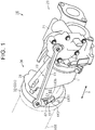
FIG. 1 is a perspective view illustrating an outline of a turbocharger of an embodiment; -
FIG. 2 is a sectional view illustrating a configuration of a turbine of the turbocharger; -
FIG. 3 is a sectional view illustrating the configuration of the turbine of the turbocharger; -
FIG. 4 is a sectional view illustrating the configuration of the turbine of the turbocharger; -
FIG. 5 is a side view illustrating a state where a drive arm and a rotating shaft rotate in a wastegate valve device of the turbocharger; -
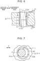
FIG. 6 is a sectional view schematically illustrating a state where the rotating shaft of the wastegate valve device is inclined; -
FIG. 7 is a sectional view taken along an arrow 7-7 inFIG. 6 ; -
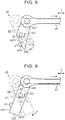
FIG. 8 is a side view illustrating a part of a turbocharger in another embodiment; and -
FIG. 9 is a side view illustrating a part of a turbocharger in another embodiment. - One embodiment of a turbocharger is described below with reference to the drawings. As illustrated in
FIG. 1 , aturbocharger 10 of the present embodiment includes acompressor housing 21 constituting acompressor 20, aturbine housing 31 constituting aturbine 30, and a bearinghousing 11 placed between thecompressor housing 21 and theturbine housing 31. The direction where threehousings compressor housing 21, and aturbine wheel 32 is accommodated inside theturbine housing 31 as illustrated inFIG. 2 . The bearinghousing 11 rotatably supports a connecting shaft connecting the compressor wheel to theturbine wheel 32. - As illustrated in
FIGS. 1 and2 , in terms of the opposite ends of theturbine housing 31 in the reference direction X, the end on the side distant from thecompressor housing 21 serves as anoutflow portion 33 to which anexhaust pipe 100 is connected. Theexhaust pipe 100 is configured such that exhaust gas flowing out from theturbine housing 31 flows through theexhaust pipe 100. Theoutflow portion 33 is provided with aflange 331 to be connected to theexhaust pipe 100. - As illustrated in
FIG. 2 , theturbine housing 31 includes ascroll passage 34 formed therein such that thescroll passage 34 extends so as to surround theturbine wheel 32. Theturbine wheel 32 rotates when the exhaust gas flowing into thescroll passage 34 is blown to theturbine wheel 32. Hereby, the compressor wheel connected to theturbine wheel 32 via the connecting shaft rotates, so that forced induction is performed in thecompressor housing 21. Note that the exhaust gas blown to theturbine wheel 32 flows through adischarge passage 35 and then flows out into theexhaust pipe 100 via theoutflow portion 33. - Further, the
turbine housing 31 is provided with awastegate port 36 formed therein. Thewastegate port 36 is a passage that connects thescroll passage 34 to thedischarge passage 35 by detouring around theturbine wheel 32. Note that, in the present embodiment, thewastegate port 36 extends in the reference direction X. - Next, a
wastegate valve device 40 of theturbocharger 10 will be described. As illustrated inFIGS. 2 and 3 , thewastegate valve device 40 includes avalve body 41 configured to open and close thewastegate port 36. Thevalve body 41 is placed on the opposite side of thewastegate port 36 with respect to theturbine wheel 32 in the reference direction X, that is, placed closer to theoutflow portion 33 than thewastegate port 36. When thevalve body 41 abuts with theturbine housing 31 as illustrated inFIG. 2 , thewastegate port 36 is closed by thevalve body 41. - In the meantime, when the
valve body 41 is distanced from theturbine housing 31 toward theoutflow portion 33 side (the right side inFIG. 3 ) as illustrated inFIG. 3 and thewastegate port 36 is not closed by thevalve body 41, that is, when thewastegate port 36 is opened, the exhaust gas flowing through thescroll passage 34 flows into thedischarge passage 35 through thewastegate port 36. When the exhaust gas passing through thescroll passage 34 flows into thedischarge passage 35 via thewastegate port 36 in a way described as above, the amount of the exhaust gas to be blown to theturbine wheel 32 is decreased. Accordingly, when thewastegate port 36 is opened, rotations of theturbine wheel 32 and the compressor wheel are restrained, thereby restraining forced induction, - Further, as illustrated in
FIG. 4 , aside wall 311 of theturbine housing 31 has a communicating hole 311a via which the inside of theturbine housing 31 communicates with the outside of theturbine housing 31, and abush 312 having a cylindrical shape is press-fitted to the communicating hole 311a. The extending direction of the communicating hole 311a, that is, the extending direction of thebush 312, is perpendicular to the reference direction X. The reference direction X is the direction perpendicular to the plane of paper ofFIG. 4 . Note that the extending direction of thebush 312 may not necessarily be perpendicular to the reference direction X as long as the extending direction of thebush 312 intersects with the reference direction X. - As illustrated in
FIGS. 2 and4 , thewastegate valve device 40 is provided with arotating shaft 42 inserted through aninsertion hole 312a formed inside thebush 312. That is, the rotatingshaft 42 is supported by theside wall 311 in a rotatable state. Aswing arm 43 is fixed to aninner portion 421 that is a part of therotating shaft 42, the part being placed inside theturbine housing 31. Theswing arm 43 supports thevalve body 41 at a position distanced, in the radial direction of therotating shaft 42, from a part of theswing arm 43 where theswing arm 43 is fixed to therotating shaft 42. Since thevalve body 41 is connected to therotating shaft 42 via theswing arm 43, when the rotatingshaft 42 and theswing arm 43 rotate, thevalve body 41 rotates. That is, when the rotatingshaft 42 and theswing arm 43 rotate in a valve-closing direction C1 that is the clockwise direction inFIGS. 2 and 3 , thevalve body 41 is displaced to a side approaching thewastegate port 36. In the meantime, when the rotatingshaft 42 and theswing arm 43 rotate in a valve-opening direction C2 that is the counterclockwise direction inFIGS. 2 and 3 , thevalve body 41 is displaced to a side distanced from thewastegate port 36. - Further, as illustrated in
FIG. 4 , thewastegate valve device 40 includes adrive arm 44 placed outside theturbine housing 31, and arod 45 rotatably connected to thedrive arm 44. As illustrated inFIG. 1 , a first end of therod 45 is connected to thedrive arm 44, while a second end of therod 45 is connected to an electrically-drivenactuator 46 supported by thecompressor housing 21. - As illustrated in
FIG. 4 , anouter portion 422 of therotating shaft 42 is fixed to thedrive arm 44. Theouter portion 422 is a part placed outside theturbine housing 31. Hereby, thedrive arm 44 rotates in an integrated manner together with the rotatingshaft 42 and theswing arm 43 around the rotatingshaft 42. Further, as illustrated inFIGS. 4 and 5 , thedrive arm 44 includes a fixedportion 441 to which therotating shaft 42 is fixed, and twoextension portions portion 441 in a direction perpendicular to the extending direction of therotating shaft 42. Note that the extending direction of theextension portions rotating shaft 42 as long as the extending direction of theextension portions rotating shaft 42. - The
rod 45 is connected to a distal part of thefirst extension portion 442 out of theextension portions rod 45 is connected to thedrive arm 44 at a position different from the fixedportion 441 that is a part to which therotating shaft 42 is fixed. Further, thesecond extension portion 443 out of theextension portions portion 441 on the opposite side from thefirst extension portion 442. - As illustrated in
FIG. 5 , in thesecond extension portion 443, an edge on the valve-opening direction C2 side is referred to as afront edge 443f, and an edge on the valve-closing direction C1 side is referred to as arear edge 443b. In this case, thefront edge 443f is inclined to a line L2 extending in the extending direction of thesecond extension portion 443, so that a distal end side thereof is placed on the valve-closing direction C1 side from a base end side thereof. Further, the interval between thefront edge 443f and therear edge 443b is gradually narrowed as it goes from the base end side of thesecond extension portion 443 toward the distal end side thereof. Further, the line L2 extending in the extending direction of thesecond extension portion 443 deviates from a line L1 extending in the extending direction of thefirst extension portion 442, along the valve-closing direction C1. That is, thedrive arm 44 has a bending shape as a whole. - Further, as illustrated in
FIGS. 1 and5 , thewastegate valve device 40 includes astopper 47 placed on the valve-opening direction C2 side from thesecond extension portion 443 at the time when thevalve body 41 closes thewastegate port 36. Thestopper 47 is placed generally right below the rotatingshaft 42 inFIG. 5 on theturbine housing 31. That is, the position of thestopper 47 is placed generally at the same position as the rotatingshaft 42 in the reference direction X. Further, thestopper 47 is placed on a rotation locus of adistal part 443t of thesecond extension portion 443. When thevalve body 41 is distanced from thewastegate port 36, thefront edge 443f of thesecond extension portion 443 abuts with thestopper 47. Note that thedistal part 443t of thesecond extension portion 443 is a part disposed on the distal side from the center of thesecond extension portion 443 in the extending direction of thesecond extension portion 443. - Note that the linear distance between an abutting part of the
drive arm 44 with thestopper 47 and a fixed part of thedrive arm 44 to therotating shaft 42 is referred to as a first linear distance B1, and the linear distance between the fixed part of thedrive arm 44 to therotating shaft 42 and a connection part of thedrive arm 44 to therod 45 is referred to as a second linear distance B2. In this case, in the present embodiment, the first linear distance B1 is shorter than the second linear distance B2. - Next, operations and effects of the
turbocharger 10 will be described. When therod 45 is displaced due to driving of theactuator 46 in a state where thewastegate port 36 is closed by thevalve body 41, so as to pull thedrive arm 44 toward thecompressor housing 21 side in the reference direction X as indicated by an arrow inFIG. 5 , thedrive arm 44, the rotatingshaft 42, and theswing arm 43 are rotated in the valve-opening direction C2. When therotating shaft 42 and theswing arm 43 are rotated in the valve-opening direction C2 as such, thevalve body 41 connected to therotating shaft 42 via theswing arm 43 is displaced so as to come closer to theoutflow portion 33. Hereby, thevalve body 41 is distanced from thewastegate port 36, so that the exhaust gas passes through thewastegate port 36 inside theturbine housing 31, as indicated by an arrow inFIG. 3 . - In this case, the exhaust gas passing through the
wastegate port 36 interferes with thevalve body 41, and then flows out into theexhaust pipe 100 via theoutflow portion 33. That is, thevalve body 41 receives a load from the exhaust gas directed toward theoutflow portion 33 through thewastegate port 36. Accordingly, theinner portion 421 of therotating shaft 42 to which thevalve body 41 is connected via theswing arm 43 is pushed toward theoutflow portion 33 side in the reference direction X, namely, toward the opposite side from thecompressor housing 21, as illustrated inFIG. 6 . - Further, when the
drive arm 44 rotates in the valve-opening direction C2 due to driving of theactuator 46, thefront edge 443f of thesecond extension portion 443 in thedrive arm 44 abuts with thestopper 47, so that further rotations of thedrive arm 44 and therotating shaft 42 in the valve-opening direction C2 are restricted. Even in this state, the driving of theactuator 46 is continued, so that the fixedportion 441 of thedrive arm 44 is displaced toward thecompressor housing 21 side in the reference direction X with the part of thedrive arm 44 abutting with thestopper 47 serving as a fulcrum. Consequently, as illustrated inFIG. 6 , theouter portion 422 of therotating shaft 42 is pulled toward thecompressor housing 21 side in the reference direction X due to a driving force P2 input into thefirst extension portion 442 from theactuator 46. - That is, when the
wastegate port 36 is opened, the rotatingshaft 42 is inclined with respect to the central axis Z of theinsertion hole 312a due to the driving force P2 transmitted from theactuator 46 to therotating shaft 42 via thedrive arm 44 and a load P1 received by thevalve body 41 from the exhaust gas, as illustrated inFIG. 6 . That is, due to actions of two forces in directions different from each other by approximately 180°, the rotatingshaft 42 is pressed against an inside opening edge 312a1 and an outside opening edge 312a2 of theinsertion hole 312a, the inside opening edge 312a1 being on the inside of theturbine housing 31, the outside opening edge 312a2 being on the outside of theturbine housing 31. In this case, as illustrated inFIG. 7 , the position of a part of the inside opening edge 312a1 abutting with the rotatingshaft 42 is different by approximately 180° from the position of a part of the outside opening edge 312a2 abutting with the rotatingshaft 42 with respect to the central axis Z. - Accordingly, in the present embodiment, when the
wastegate port 36 is opened, thedrive arm 44 is pressed against thestopper 47. Further, by using two forces in application directions different from each other by approximately 180°, that is, the driving force P2 from theactuator 46 and the load P1 received by thevalve body 41 from the exhaust gas, the rotatingshaft 42 is pressed against the opening edges 312a1, 312a2. More specifically, the rotatingshaft 42 is pressed against the inside opening edge 312a1 at a position on theoutflow portion 33 side, and therotating shaft 42 is pressed against the outside opening edge 312a2 at a position on thecompressor housing 21 side. Accordingly, even if a force to displace thevalve body 41 toward theoutflow portion 33 side is applied to thevalve body 41, the rotatingshaft 42 is not displaced. That is, a state where the rotatingshaft 42 is inclined is maintained. Further, even if the pressure of the exhaust gas interfering with thevalve body 41 pulsates, the forces to press the rotatingshaft 42 against the opening edges 312a1, 312a2 just fluctuate, so that it is possible to restrain therotating shaft 42, theswing arm 43, and thevalve body 41 from vibrating. That is, it is possible to restrain the occurrence of abnormal noise caused when the rotatingshaft 42 abuts with the opening edges 312a1, 312a2. - As illustrated in
FIGS. 6 and 7 , a small gap S is provided between aperipheral wall 312b of theinsertion hole 312a and therotating shaft 42, so that the exhaust gas flowing through theturbine housing 31 might leak outside via the gap S. The possibility that the exhaust gas leaks outside as such becomes lower as the occupying ratio of therotating shaft 42 in the volume of theinsertion hole 312a is larger. - Here, when the rotating
shaft 42 vibrates, the occupying ratio of therotating shaft 42 in the volume of theinsertion hole 312a fluctuates. That is, the possibility that the exhaust gas leaks outside fluctuates. In this regard, in the present embodiment, it is possible to maintain therotating shaft 42 to be inclined in theinsertion hole 312a as illustrated inFIG. 6 . In this case, since the position of the part of the inside opening edge 312a1 abutting with the rotatingshaft 42 is different by approximately 180° from the position of the part of the outside opening edge 312a2 abutting with the rotatingshaft 42 with respect to the central axis Z, it is possible to maintain the maximum occupying ratio of therotating shaft 42 in the volume of theinsertion hole 312a. Accordingly, in comparison with a case where the rotatingshaft 42 vibrates in theinsertion hole 312a, the exhaust gas flow through theturbine housing 31 can hardly leak outside via the gap S. - Note that, in the present embodiment, the
stopper 47 is placed on the rotation locus of thedistal part 443t of thesecond extension portion 443 in thedrive arm 44, and the first linear distance B1 is shorter than the second linear distance B2. As a result, in comparison with a case where the first linear distance B1 is equal to or more than the second linear distance B2, it is possible to increase a force to be input into theouter portion 422 of therotating shaft 42 at the time when the rotation of thedrive arm 44 in the valve-opening direction C2 is restricted by thestopper 47. As a result, it is possible to increase the forces to press the rotatingshaft 42 against the opening edges 312a1, 312a2, and eventually, it is possible to enhance vibration restraint effects of therotating shaft 42, theswing arm 43, and thevalve body 41. - Further, the
front edge 443f of thesecond extension portion 443 in thedrive arm 44 is inclined so that its distal end side is placed on the valve-closing direction C1 side with respect to its base end side. This makes it possible to restrain a difference between the position of therotating shaft 42 and the position of thestopper 47 from increasing in the reference direction X. - Here, a comparative example in which the
front edge 443f is not inclined like the present embodiment is illustrated inFIG. 9 . In the comparative example, as illustrated inFIG. 9 , when thestopper 47 is placed on theoutflow portion 33 side in the reference direction X, thefront edge 443f can be placed so as not to abut with thestopper 47 at the time when thewastegate port 36 is closed by thevalve body 41. - In this regard, in the present embodiment, the
stopper 47 can be placed distanced from theoutflow portion 33, in comparison with the comparative example. That is, it is not necessary to place thestopper 47 closer to theoutflow portion 33 in the reference direction X. Further, when thestopper 47 is placed distanced from theoutflow portion 33 as such, the distal end of thefirst extension portion 442 in thedrive arm 44 can hardly approach theoutflow portion 33 in the reference direction X in a state where thewastegate port 36 is closed by thevalve body 41. That is, it is not necessary to set a large difference between the position of theflange 331 and the position of therotating shaft 42 in the reference direction X. This accordingly makes it possible to restrain upsizing of theturbine housing 31 in the reference direction X. - Further, the
stopper 47 is placed at a position which is closer to thedrive arm 44 than theflange 331. Accordingly, even if therotating shaft 42 is placed near theflange 331 like the present embodiment, it is possible to avoid such a situation that thedrive arm 44 makes contact with theflange 331 at the time when thedrive arm 44 is rotated in the valve-opening direction C2. - Note that the above embodiment can be modified to the following other embodiments. The
second extension portion 443 in thedrive arm 44 may have any given shape other than the shape described in the embodiment, provided that thefront edge 443f is inclined so that the distal end side is placed on the valve-closing direction C1 side with respect to the base end side. For example, as illustrated inFIG. 8 , thesecond extension portion 443 may have such a shape in which thefront edge 443f is inclined so that the distal end side is placed on the valve-closing direction C1 side with respect to the base end side, but therear edge 443b is not inclined. That is, differently from the description in the embodiment, thedrive arm 44 may have a shape that is not bent in the middle from the distal end of thefirst extension portion 442 toward the distal end of thesecond extension portion 443. - The
second extension portion 443 in thedrive arm 44 may have any given configuration other than the configuration described in the embodiment, provided that thesecond extension portion 443 extends from the part of the fixedportion 441 on the opposite side from thefirst extension portion 442. For example, as illustrated inFIG. 9 , thesecond extension portion 443 may be configured such that thefront edge 443f is not inclined. - In the embodiment, the
stopper 47 is configured to abut with thedistal part 443t of thesecond extension portion 443. However, thestopper 47 may be placed so that a part of thesecond extension portion 443 on the base end side from the distal part thereof abuts with thestopper 47, as indicated by the alternate long and short dash line inFIG. 9 , provided that thestopper 47 abuts with thefront edge 443f of thesecond extension portion 443.
Claims (3)
- A turbocharger (10) in which a turbine housing (31) and a compressor housing (21) are arranged in a reference direction (X), wherein an outflow portion (33) via which exhaust gas flowing through the turbine housing flows out into an exhaust pipe is provided, the outflow portion being provided on a distant side of the turbine housing from the compressor housing in the reference direction, the turbocharger comprising:a valve body (41) placed on an outflow portion side in the reference direction from a wastegate port (36) and configured to open and close the wastegate port (36), the wastegate port (36) inside the turbine housing being configured to cause the exhaust gas to detour around a turbine wheel (32);a rotating shaft (42) extending in a direction intersecting with the reference direction, the rotating shaft (42) being inserted through an insertion hole (312a) provided on a side wall of the turbine housing;a swing arm (43) fixed to the rotating shaft (42) and configured to support the valve body (41) at a position distanced from a part of the swing arm (43) fixed to the rotating shaft (42) in a radial direction of the rotating shaft (42);a drive arm (44) placed outside the turbine housing and fixed to the rotating shaft (42);a rod (45) rotatably connected to the drive arm (44), the rod (45) being connected to the drive arm (44) at a position distanced from a part where the rotating shaft (42) is fixed to the drive arm (44); andan actuator (46), wherein:the rod (45) is configured to be displace toward a side approaching the compressor housing in the reference direction by driving of the actuator (46);the drive arm (44), the rotating shaft (42), and the swing arm (43) are configured to rotate in a valve-opening direction (C2) when the rod (45) is displaced, so that the valve body (41) is displaced toward a side approaching the outflow portion so as to be distanced from the wastegate port (36);the drive arm (44) includes a fixed portion (441) to which the rotating shaft (42) is fixed, a first extension portion (442), and a second extension portion (443);the first extension portion (442) extends from the fixed portion (441) in a first direction (L1) intersecting with an extending direction of the rotating shaft (42) and the rod (45) is connected to the first extension portion (442);the second extension portion (443) extends in a second direction (L2) intersecting with the extending direction of the rotating shaft (42) from a part of the fixed portion (441) on an opposite side from the first extension portion (442);the turbine housing is provided with a stopper (47) configured to abut with the second extension portion (443);the stopper (47) is on a valve-opening direction side from the second extension portion (443) when the valve body (41) closes the wastegate port (36);the stopper (47) is configured to abut with the second extension portion (443) when the valve body (41) is distanced from the wastegate port (36); andthe valve-opening direction (C2) is one rotation direction around the rotating shaft (42).
- The turbocharger according to claim 1, wherein the stopper (47) is placed on a rotational locus of a distal part (443t) which is a part of the second extension portion (443) on a distal end side from a center of the second extension portion (443).
- The turbocharger according to claim 1 or 2, wherein:the outflow portion includes a flange (331) configured to connect the exhaust pipe to the turbine housing;a distal end side of a front edge (443f) of the second extension portion (443) is on a valve-closing direction (C1) side from a base end side of the front edge (443f) of the second extension portion (443);the stopper (47) is placed on a compressor housing side in the reference direction from the flange (331);the valve-closing direction (C1) is a rotation direction reverse to the valve-opening direction (C2); andthe front edge (443f) of the second extension portion (443) is an edge of the second extension portion (443) on the valve-opening direction (C2) side.
Applications Claiming Priority (1)
| Application Number | Priority Date | Filing Date | Title |
|---|---|---|---|
| JP2017047387A JP6724826B2 (en) | 2017-03-13 | 2017-03-13 | Supercharger |
Publications (2)
| Publication Number | Publication Date |
|---|---|
| EP3375999A1 true EP3375999A1 (en) | 2018-09-19 |
| EP3375999B1 EP3375999B1 (en) | 2021-11-17 |
Family
ID=61626938
Family Applications (1)
| Application Number | Title | Priority Date | Filing Date |
|---|---|---|---|
| EP18161071.8A Not-in-force EP3375999B1 (en) | 2017-03-13 | 2018-03-09 | Turbocharger |
Country Status (3)
| Country | Link |
|---|---|
| US (1) | US10422275B2 (en) |
| EP (1) | EP3375999B1 (en) |
| JP (1) | JP6724826B2 (en) |
Families Citing this family (1)
| Publication number | Priority date | Publication date | Assignee | Title |
|---|---|---|---|---|
| JP2020041516A (en) * | 2018-09-13 | 2020-03-19 | トヨタ自動車株式会社 | Control device for turbocharger |
Citations (5)
| Publication number | Priority date | Publication date | Assignee | Title |
|---|---|---|---|---|
| US20090020167A1 (en) * | 2007-07-20 | 2009-01-22 | Koester David J | Rotary Actuator Lever with Locking Device |
| JP2012067698A (en) | 2010-09-24 | 2012-04-05 | Toyota Motor Corp | Wastegate valve device |
| GB2530824A (en) * | 2015-02-13 | 2016-04-06 | Ford Global Tech Llc | Turbocharger wastegate linkage assembly |
| WO2017119012A1 (en) * | 2016-01-08 | 2017-07-13 | マツダ株式会社 | Valve mechanism and engine gas-exhaustion device provided with valve mechanism |
| EP3199778A1 (en) * | 2016-01-29 | 2017-08-02 | Volkswagen Aktiengesellschaft | Exhaust gas turbocharger for a combustion engine |
Family Cites Families (7)
| Publication number | Priority date | Publication date | Assignee | Title |
|---|---|---|---|---|
| FR2864994A1 (en) * | 2004-01-12 | 2005-07-15 | Remi Curtil | Supercharged internal combustion engine e.g. diesel engine, for motor vehicle e.g. truck, has turbine admitting completely air-gas mixture, when air flow is desired, where outer wall of turbine is maintained at low temperature by air film |
| US20070204616A1 (en) * | 2006-03-06 | 2007-09-06 | Honeywell International, Inc. | Swing valve for a turbocharger with stacked valve members, and two-stage turbocharger system incorporating same |
| JP5728943B2 (en) * | 2010-12-28 | 2015-06-03 | いすゞ自動車株式会社 | Turbo system and switchable two-stage turbocharger turbo system |
| DE102011076587A1 (en) * | 2011-05-27 | 2012-11-29 | Continental Automotive Gmbh | Exhaust gas turbocharger with a ball valve wastegate valve with tension-relieved crank arm |
| KR102076645B1 (en) * | 2012-12-14 | 2020-05-19 | 보르그워너 인코퍼레이티드 | Control arrangement of an exhaust-gas turbocharger |
| US9249721B2 (en) * | 2014-03-03 | 2016-02-02 | Honeywell International Inc. | Turbocharger turbine wastegate mechanism |
| JP6822239B2 (en) * | 2017-03-16 | 2021-01-27 | トヨタ自動車株式会社 | Turbocharger wastegate valve |
-
2017
- 2017-03-13 JP JP2017047387A patent/JP6724826B2/en active Active
-
2018
- 2018-03-07 US US15/913,970 patent/US10422275B2/en active Active
- 2018-03-09 EP EP18161071.8A patent/EP3375999B1/en not_active Not-in-force
Patent Citations (5)
| Publication number | Priority date | Publication date | Assignee | Title |
|---|---|---|---|---|
| US20090020167A1 (en) * | 2007-07-20 | 2009-01-22 | Koester David J | Rotary Actuator Lever with Locking Device |
| JP2012067698A (en) | 2010-09-24 | 2012-04-05 | Toyota Motor Corp | Wastegate valve device |
| GB2530824A (en) * | 2015-02-13 | 2016-04-06 | Ford Global Tech Llc | Turbocharger wastegate linkage assembly |
| WO2017119012A1 (en) * | 2016-01-08 | 2017-07-13 | マツダ株式会社 | Valve mechanism and engine gas-exhaustion device provided with valve mechanism |
| EP3199778A1 (en) * | 2016-01-29 | 2017-08-02 | Volkswagen Aktiengesellschaft | Exhaust gas turbocharger for a combustion engine |
Also Published As
| Publication number | Publication date |
|---|---|
| US20180258841A1 (en) | 2018-09-13 |
| EP3375999B1 (en) | 2021-11-17 |
| JP6724826B2 (en) | 2020-07-15 |
| JP2018150866A (en) | 2018-09-27 |
| US10422275B2 (en) | 2019-09-24 |
Similar Documents
| Publication | Publication Date | Title |
|---|---|---|
| JP6354847B2 (en) | Variable flow rate valve mechanism and turbocharger | |
| JP6017798B2 (en) | Exhaust flow path valve device | |
| JP2009203835A (en) | Exhaust bypass valve for turbocharger | |
| CN106574549A (en) | Variable flow valve mechanism and supercharger | |
| US10215089B2 (en) | Variable-flow-rate valve mechanism and turbocharger | |
| US10570814B2 (en) | Waste-gate valve and turbocharger | |
| CN108533391B (en) | Turbocharger | |
| EP3375999B1 (en) | Turbocharger | |
| JP2018155139A (en) | Turbocharger waste gate valve | |
| KR20180070596A (en) | Bypass valve for turbocharger | |
| WO2019198284A1 (en) | Spring washer, variable flow rate valve mechanism, and turbocharger | |
| JP5446969B2 (en) | Compressor | |
| WO2020075370A1 (en) | Variable geometry mechanism and supercharger | |
| JP6390703B2 (en) | Turbocharger | |
| JP6217597B2 (en) | Wastegate valve drive mechanism | |
| US10876466B2 (en) | Wave washer and variable-flow-rate valve | |
| JP5751057B2 (en) | Valve device | |
| JP6566134B2 (en) | Variable flow rate valve mechanism and turbocharger | |
| WO2015190361A1 (en) | Supercharger | |
| US20180320581A1 (en) | Variable flow rate valve mechanism and turbocharger | |
| CN106460647B (en) | supercharger | |
| JP6905165B2 (en) | Silent valve device | |
| US10934882B2 (en) | Turbocharger | |
| CN219413629U (en) | Muffler valve | |
| JP5747704B2 (en) | Valve device |
Legal Events
| Date | Code | Title | Description |
|---|---|---|---|
| PUAI | Public reference made under article 153(3) epc to a published international application that has entered the european phase |
Free format text: ORIGINAL CODE: 0009012 |
|
| STAA | Information on the status of an ep patent application or granted ep patent |
Free format text: STATUS: REQUEST FOR EXAMINATION WAS MADE |
|
| 17P | Request for examination filed |
Effective date: 20180309 |
|
| AK | Designated contracting states |
Kind code of ref document: A1 Designated state(s): AL AT BE BG CH CY CZ DE DK EE ES FI FR GB GR HR HU IE IS IT LI LT LU LV MC MK MT NL NO PL PT RO RS SE SI SK SM TR |
|
| AX | Request for extension of the european patent |
Extension state: BA ME |
|
| STAA | Information on the status of an ep patent application or granted ep patent |
Free format text: STATUS: EXAMINATION IS IN PROGRESS |
|
| 17Q | First examination report despatched |
Effective date: 20200131 |
|
| GRAP | Despatch of communication of intention to grant a patent |
Free format text: ORIGINAL CODE: EPIDOSNIGR1 |
|
| STAA | Information on the status of an ep patent application or granted ep patent |
Free format text: STATUS: GRANT OF PATENT IS INTENDED |
|
| INTG | Intention to grant announced |
Effective date: 20210503 |
|
| GRAJ | Information related to disapproval of communication of intention to grant by the applicant or resumption of examination proceedings by the epo deleted |
Free format text: ORIGINAL CODE: EPIDOSDIGR1 |
|
| STAA | Information on the status of an ep patent application or granted ep patent |
Free format text: STATUS: EXAMINATION IS IN PROGRESS |
|
| INTC | Intention to grant announced (deleted) | ||
| GRAP | Despatch of communication of intention to grant a patent |
Free format text: ORIGINAL CODE: EPIDOSNIGR1 |
|
| STAA | Information on the status of an ep patent application or granted ep patent |
Free format text: STATUS: GRANT OF PATENT IS INTENDED |
|
| GRAS | Grant fee paid |
Free format text: ORIGINAL CODE: EPIDOSNIGR3 |
|
| GRAA | (expected) grant |
Free format text: ORIGINAL CODE: 0009210 |
|
| STAA | Information on the status of an ep patent application or granted ep patent |
Free format text: STATUS: THE PATENT HAS BEEN GRANTED |
|
| INTG | Intention to grant announced |
Effective date: 20211001 |
|
| AK | Designated contracting states |
Kind code of ref document: B1 Designated state(s): AL AT BE BG CH CY CZ DE DK EE ES FI FR GB GR HR HU IE IS IT LI LT LU LV MC MK MT NL NO PL PT RO RS SE SI SK SM TR |
|
| REG | Reference to a national code |
Ref country code: GB Ref legal event code: FG4D |
|
| REG | Reference to a national code |
Ref country code: IE Ref legal event code: FG4D |
|
| REG | Reference to a national code |
Ref country code: DE Ref legal event code: R096 Ref document number: 602018026696 Country of ref document: DE |
|
| REG | Reference to a national code |
Ref country code: AT Ref legal event code: REF Ref document number: 1448228 Country of ref document: AT Kind code of ref document: T Effective date: 20211215 |
|
| REG | Reference to a national code |
Ref country code: LT Ref legal event code: MG9D |
|
| REG | Reference to a national code |
Ref country code: NL Ref legal event code: MP Effective date: 20211117 |
|
| REG | Reference to a national code |
Ref country code: AT Ref legal event code: MK05 Ref document number: 1448228 Country of ref document: AT Kind code of ref document: T Effective date: 20211117 |
|
| PG25 | Lapsed in a contracting state [announced via postgrant information from national office to epo] |
Ref country code: RS Free format text: LAPSE BECAUSE OF FAILURE TO SUBMIT A TRANSLATION OF THE DESCRIPTION OR TO PAY THE FEE WITHIN THE PRESCRIBED TIME-LIMIT Effective date: 20211117 Ref country code: LT Free format text: LAPSE BECAUSE OF FAILURE TO SUBMIT A TRANSLATION OF THE DESCRIPTION OR TO PAY THE FEE WITHIN THE PRESCRIBED TIME-LIMIT Effective date: 20211117 Ref country code: FI Free format text: LAPSE BECAUSE OF FAILURE TO SUBMIT A TRANSLATION OF THE DESCRIPTION OR TO PAY THE FEE WITHIN THE PRESCRIBED TIME-LIMIT Effective date: 20211117 Ref country code: BG Free format text: LAPSE BECAUSE OF FAILURE TO SUBMIT A TRANSLATION OF THE DESCRIPTION OR TO PAY THE FEE WITHIN THE PRESCRIBED TIME-LIMIT Effective date: 20220217 Ref country code: AT Free format text: LAPSE BECAUSE OF FAILURE TO SUBMIT A TRANSLATION OF THE DESCRIPTION OR TO PAY THE FEE WITHIN THE PRESCRIBED TIME-LIMIT Effective date: 20211117 |
|
| PGFP | Annual fee paid to national office [announced via postgrant information from national office to epo] |
Ref country code: GB Payment date: 20220127 Year of fee payment: 5 |
|
| PG25 | Lapsed in a contracting state [announced via postgrant information from national office to epo] |
Ref country code: IS Free format text: LAPSE BECAUSE OF FAILURE TO SUBMIT A TRANSLATION OF THE DESCRIPTION OR TO PAY THE FEE WITHIN THE PRESCRIBED TIME-LIMIT Effective date: 20220317 Ref country code: SE Free format text: LAPSE BECAUSE OF FAILURE TO SUBMIT A TRANSLATION OF THE DESCRIPTION OR TO PAY THE FEE WITHIN THE PRESCRIBED TIME-LIMIT Effective date: 20211117 Ref country code: PT Free format text: LAPSE BECAUSE OF FAILURE TO SUBMIT A TRANSLATION OF THE DESCRIPTION OR TO PAY THE FEE WITHIN THE PRESCRIBED TIME-LIMIT Effective date: 20220317 Ref country code: PL Free format text: LAPSE BECAUSE OF FAILURE TO SUBMIT A TRANSLATION OF THE DESCRIPTION OR TO PAY THE FEE WITHIN THE PRESCRIBED TIME-LIMIT Effective date: 20211117 Ref country code: NO Free format text: LAPSE BECAUSE OF FAILURE TO SUBMIT A TRANSLATION OF THE DESCRIPTION OR TO PAY THE FEE WITHIN THE PRESCRIBED TIME-LIMIT Effective date: 20220217 Ref country code: NL Free format text: LAPSE BECAUSE OF FAILURE TO SUBMIT A TRANSLATION OF THE DESCRIPTION OR TO PAY THE FEE WITHIN THE PRESCRIBED TIME-LIMIT Effective date: 20211117 Ref country code: LV Free format text: LAPSE BECAUSE OF FAILURE TO SUBMIT A TRANSLATION OF THE DESCRIPTION OR TO PAY THE FEE WITHIN THE PRESCRIBED TIME-LIMIT Effective date: 20211117 Ref country code: HR Free format text: LAPSE BECAUSE OF FAILURE TO SUBMIT A TRANSLATION OF THE DESCRIPTION OR TO PAY THE FEE WITHIN THE PRESCRIBED TIME-LIMIT Effective date: 20211117 Ref country code: GR Free format text: LAPSE BECAUSE OF FAILURE TO SUBMIT A TRANSLATION OF THE DESCRIPTION OR TO PAY THE FEE WITHIN THE PRESCRIBED TIME-LIMIT Effective date: 20220218 Ref country code: ES Free format text: LAPSE BECAUSE OF FAILURE TO SUBMIT A TRANSLATION OF THE DESCRIPTION OR TO PAY THE FEE WITHIN THE PRESCRIBED TIME-LIMIT Effective date: 20211117 |
|
| PGFP | Annual fee paid to national office [announced via postgrant information from national office to epo] |
Ref country code: FR Payment date: 20220209 Year of fee payment: 5 |
|
| PG25 | Lapsed in a contracting state [announced via postgrant information from national office to epo] |
Ref country code: SM Free format text: LAPSE BECAUSE OF FAILURE TO SUBMIT A TRANSLATION OF THE DESCRIPTION OR TO PAY THE FEE WITHIN THE PRESCRIBED TIME-LIMIT Effective date: 20211117 Ref country code: SK Free format text: LAPSE BECAUSE OF FAILURE TO SUBMIT A TRANSLATION OF THE DESCRIPTION OR TO PAY THE FEE WITHIN THE PRESCRIBED TIME-LIMIT Effective date: 20211117 Ref country code: RO Free format text: LAPSE BECAUSE OF FAILURE TO SUBMIT A TRANSLATION OF THE DESCRIPTION OR TO PAY THE FEE WITHIN THE PRESCRIBED TIME-LIMIT Effective date: 20211117 Ref country code: EE Free format text: LAPSE BECAUSE OF FAILURE TO SUBMIT A TRANSLATION OF THE DESCRIPTION OR TO PAY THE FEE WITHIN THE PRESCRIBED TIME-LIMIT Effective date: 20211117 Ref country code: DK Free format text: LAPSE BECAUSE OF FAILURE TO SUBMIT A TRANSLATION OF THE DESCRIPTION OR TO PAY THE FEE WITHIN THE PRESCRIBED TIME-LIMIT Effective date: 20211117 Ref country code: CZ Free format text: LAPSE BECAUSE OF FAILURE TO SUBMIT A TRANSLATION OF THE DESCRIPTION OR TO PAY THE FEE WITHIN THE PRESCRIBED TIME-LIMIT Effective date: 20211117 |
|
| REG | Reference to a national code |
Ref country code: DE Ref legal event code: R097 Ref document number: 602018026696 Country of ref document: DE |
|
| PLBE | No opposition filed within time limit |
Free format text: ORIGINAL CODE: 0009261 |
|
| STAA | Information on the status of an ep patent application or granted ep patent |
Free format text: STATUS: NO OPPOSITION FILED WITHIN TIME LIMIT |
|
| 26N | No opposition filed |
Effective date: 20220818 |
|
| PG25 | Lapsed in a contracting state [announced via postgrant information from national office to epo] |
Ref country code: MC Free format text: LAPSE BECAUSE OF FAILURE TO SUBMIT A TRANSLATION OF THE DESCRIPTION OR TO PAY THE FEE WITHIN THE PRESCRIBED TIME-LIMIT Effective date: 20211117 Ref country code: AL Free format text: LAPSE BECAUSE OF FAILURE TO SUBMIT A TRANSLATION OF THE DESCRIPTION OR TO PAY THE FEE WITHIN THE PRESCRIBED TIME-LIMIT Effective date: 20211117 |
|
| REG | Reference to a national code |
Ref country code: CH Ref legal event code: PL |
|
| PG25 | Lapsed in a contracting state [announced via postgrant information from national office to epo] |
Ref country code: SI Free format text: LAPSE BECAUSE OF FAILURE TO SUBMIT A TRANSLATION OF THE DESCRIPTION OR TO PAY THE FEE WITHIN THE PRESCRIBED TIME-LIMIT Effective date: 20211117 |
|
| REG | Reference to a national code |
Ref country code: BE Ref legal event code: MM Effective date: 20220331 |
|
| PG25 | Lapsed in a contracting state [announced via postgrant information from national office to epo] |
Ref country code: LU Free format text: LAPSE BECAUSE OF NON-PAYMENT OF DUE FEES Effective date: 20220309 Ref country code: LI Free format text: LAPSE BECAUSE OF NON-PAYMENT OF DUE FEES Effective date: 20220331 Ref country code: IE Free format text: LAPSE BECAUSE OF NON-PAYMENT OF DUE FEES Effective date: 20220309 Ref country code: CH Free format text: LAPSE BECAUSE OF NON-PAYMENT OF DUE FEES Effective date: 20220331 |
|
| PG25 | Lapsed in a contracting state [announced via postgrant information from national office to epo] |
Ref country code: BE Free format text: LAPSE BECAUSE OF NON-PAYMENT OF DUE FEES Effective date: 20220331 |
|
| PG25 | Lapsed in a contracting state [announced via postgrant information from national office to epo] |
Ref country code: IT Free format text: LAPSE BECAUSE OF FAILURE TO SUBMIT A TRANSLATION OF THE DESCRIPTION OR TO PAY THE FEE WITHIN THE PRESCRIBED TIME-LIMIT Effective date: 20211117 |
|
| PGFP | Annual fee paid to national office [announced via postgrant information from national office to epo] |
Ref country code: DE Payment date: 20230131 Year of fee payment: 6 |
|
| P01 | Opt-out of the competence of the unified patent court (upc) registered |
Effective date: 20230427 |
|
| REG | Reference to a national code |
Ref country code: DE Ref legal event code: R084 Ref document number: 602018026696 Country of ref document: DE |
|
| GBPC | Gb: european patent ceased through non-payment of renewal fee |
Effective date: 20230309 |
|
| PG25 | Lapsed in a contracting state [announced via postgrant information from national office to epo] |
Ref country code: GB Free format text: LAPSE BECAUSE OF NON-PAYMENT OF DUE FEES Effective date: 20230309 |
|
| PG25 | Lapsed in a contracting state [announced via postgrant information from national office to epo] |
Ref country code: GB Free format text: LAPSE BECAUSE OF NON-PAYMENT OF DUE FEES Effective date: 20230309 Ref country code: FR Free format text: LAPSE BECAUSE OF NON-PAYMENT OF DUE FEES Effective date: 20230331 |
|
| PG25 | Lapsed in a contracting state [announced via postgrant information from national office to epo] |
Ref country code: HU Free format text: LAPSE BECAUSE OF FAILURE TO SUBMIT A TRANSLATION OF THE DESCRIPTION OR TO PAY THE FEE WITHIN THE PRESCRIBED TIME-LIMIT; INVALID AB INITIO Effective date: 20180309 |
|
| PG25 | Lapsed in a contracting state [announced via postgrant information from national office to epo] |
Ref country code: MK Free format text: LAPSE BECAUSE OF FAILURE TO SUBMIT A TRANSLATION OF THE DESCRIPTION OR TO PAY THE FEE WITHIN THE PRESCRIBED TIME-LIMIT Effective date: 20211117 Ref country code: CY Free format text: LAPSE BECAUSE OF FAILURE TO SUBMIT A TRANSLATION OF THE DESCRIPTION OR TO PAY THE FEE WITHIN THE PRESCRIBED TIME-LIMIT Effective date: 20211117 |
|
| PG25 | Lapsed in a contracting state [announced via postgrant information from national office to epo] |
Ref country code: TR Free format text: LAPSE BECAUSE OF FAILURE TO SUBMIT A TRANSLATION OF THE DESCRIPTION OR TO PAY THE FEE WITHIN THE PRESCRIBED TIME-LIMIT Effective date: 20211117 |
|
| PG25 | Lapsed in a contracting state [announced via postgrant information from national office to epo] |
Ref country code: MT Free format text: LAPSE BECAUSE OF FAILURE TO SUBMIT A TRANSLATION OF THE DESCRIPTION OR TO PAY THE FEE WITHIN THE PRESCRIBED TIME-LIMIT Effective date: 20211117 |
|
| REG | Reference to a national code |
Ref country code: DE Ref legal event code: R119 Ref document number: 602018026696 Country of ref document: DE |
|
| PG25 | Lapsed in a contracting state [announced via postgrant information from national office to epo] |
Ref country code: DE Free format text: LAPSE BECAUSE OF NON-PAYMENT OF DUE FEES Effective date: 20241001 |
|
| PG25 | Lapsed in a contracting state [announced via postgrant information from national office to epo] |
Ref country code: DE Free format text: LAPSE BECAUSE OF NON-PAYMENT OF DUE FEES Effective date: 20241001 |