EP3375920A1 - Fiber structure - Google Patents
Fiber structure Download PDFInfo
- Publication number
- EP3375920A1 EP3375920A1 EP16864030.8A EP16864030A EP3375920A1 EP 3375920 A1 EP3375920 A1 EP 3375920A1 EP 16864030 A EP16864030 A EP 16864030A EP 3375920 A1 EP3375920 A1 EP 3375920A1
- Authority
- EP
- European Patent Office
- Prior art keywords
- yarns
- laminate
- fiber
- main axis
- structural
- Prior art date
- Legal status (The legal status is an assumption and is not a legal conclusion. Google has not performed a legal analysis and makes no representation as to the accuracy of the status listed.)
- Granted
Links
- 239000000835 fiber Substances 0.000 title claims abstract description 253
- 230000002787 reinforcement Effects 0.000 claims abstract description 106
- 239000003733 fiber-reinforced composite Substances 0.000 claims description 16
- 239000011347 resin Substances 0.000 claims description 9
- 229920005989 resin Polymers 0.000 claims description 9
- 239000011159 matrix material Substances 0.000 claims description 8
- 238000003475 lamination Methods 0.000 abstract 1
- 239000000463 material Substances 0.000 description 16
- 239000004744 fabric Substances 0.000 description 11
- 238000000034 method Methods 0.000 description 5
- 238000004519 manufacturing process Methods 0.000 description 3
- 239000007788 liquid Substances 0.000 description 2
- 229920001187 thermosetting polymer Polymers 0.000 description 2
- ICXAPFWGVRTEKV-UHFFFAOYSA-N 2-[4-(1,3-benzoxazol-2-yl)phenyl]-1,3-benzoxazole Chemical compound C1=CC=C2OC(C3=CC=C(C=C3)C=3OC4=CC=CC=C4N=3)=NC2=C1 ICXAPFWGVRTEKV-UHFFFAOYSA-N 0.000 description 1
- 239000004699 Ultra-high molecular weight polyethylene Substances 0.000 description 1
- 229920006231 aramid fiber Polymers 0.000 description 1
- 238000005452 bending Methods 0.000 description 1
- 230000003247 decreasing effect Effects 0.000 description 1
- 239000003365 glass fiber Substances 0.000 description 1
- 239000002241 glass-ceramic Substances 0.000 description 1
- 239000012784 inorganic fiber Substances 0.000 description 1
- 239000002184 metal Substances 0.000 description 1
- 230000000704 physical effect Effects 0.000 description 1
- 238000001721 transfer moulding Methods 0.000 description 1
- 229920000785 ultra high molecular weight polyethylene Polymers 0.000 description 1
Images




Classifications
-
- D—TEXTILES; PAPER
- D03—WEAVING
- D03D—WOVEN FABRICS; METHODS OF WEAVING; LOOMS
- D03D1/00—Woven fabrics designed to make specified articles
-
- D—TEXTILES; PAPER
- D03—WEAVING
- D03D—WOVEN FABRICS; METHODS OF WEAVING; LOOMS
- D03D11/00—Double or multi-ply fabrics not otherwise provided for
-
- D—TEXTILES; PAPER
- D03—WEAVING
- D03D—WOVEN FABRICS; METHODS OF WEAVING; LOOMS
- D03D15/00—Woven fabrics characterised by the material, structure or properties of the fibres, filaments, yarns, threads or other warp or weft elements used
- D03D15/50—Woven fabrics characterised by the material, structure or properties of the fibres, filaments, yarns, threads or other warp or weft elements used characterised by the properties of the yarns or threads
- D03D15/573—Tensile strength
-
- D—TEXTILES; PAPER
- D10—INDEXING SCHEME ASSOCIATED WITH SUBLASSES OF SECTION D, RELATING TO TEXTILES
- D10B—INDEXING SCHEME ASSOCIATED WITH SUBLASSES OF SECTION D, RELATING TO TEXTILES
- D10B2505/00—Industrial
- D10B2505/02—Reinforcing materials; Prepregs
Definitions
- the present invention relates to a fiber structure that is configured by multiple laminates.
- Fiber-reinforced composites have been used as a light-weight, high-strength material.
- the fiber-reinforced composites include reinforcement fibers combined with a matrix such as resin and metal. This improves the dynamic property (mechanical property) of the fiber-reinforced composites compared with the matrix itself.
- the fiber-reinforced composites are therefore preferable as a structural component.
- resin is preferably used as the matrix since the weight of the structural component will be reduced.
- a fiber structure is used as the base material of such a fiber-reinforced composite.
- the fiber structure includes a structure in which yarn main axes of reinforcement fiber yarns extend in two directions at 0 degrees and 90 degrees to increase the dynamic property in two directions when the fiber structure is used in the fiber-reinforced composite.
- Such a biaxial fiber structure is produced by stacking fiber layers in which reinforcement fiber yarns are oriented in one direction in such a manner that the yarn main axis of the reinforcement fiber yarns of one fiber layer is orthogonal to the yarn main axis of the reinforcement fiber yarns of another fiber layer.
- Patent Document 1 discloses a fabric base material configured by fiber layers in which the reinforcement fiber yarns are oriented in one direction.
- the fabric base material is constituted by stacking two fiber layers.
- Each fiber layer includes reinforced fiber warps, which are arranged parallel to each other, and auxiliary yarns, each of which is arranged between the adjacent reinforced fiber warps and extends in the same direction as the reinforced fiber warps.
- the reinforced fiber warps of each fiber layer extend in the same direction as the reinforced fiber warps of the other fiber layer and are shifted in an arrangement direction in a state in which the reinforced fiber warps partially overlap the reinforced fiber warps of the other fiber layer.
- the reinforced fiber warps and the auxiliary yarns are joined with intralayer structural yarns.
- the fiber layers are joined with intermediate structural yarns to form a unidirectional fabric base material.
- Patent Document 1 Japanese Laid-Open Patent Publication No. 2013-133555
- a fiber structure including a plurality of laminates is provided.
- the laminates each include a plurality of stacked fiber layers.
- the fiber layers each include reinforcement fiber yarns, auxiliary yarns, and intralayer structural yarns.
- the reinforcement fiber yarns and the auxiliary yarns are arranged alternately.
- the intralayer structural yarns join the reinforcement fiber yarns and the auxiliary yarns together in an arrangement direction.
- yarn main axis directions of the reinforcement fiber yarns and the auxiliary yarns of each of the fiber layers are the same; the reinforcement fiber yarns are arranged in such a manner that the relative positions are shifted in a stacking direction of the fiber layers with the reinforcement fiber yarns overlapping each other; the auxiliary yarns are arranged in such a manner that the relative positions are shifted; and the fiber layers are joined with intermediate structural yarns engaged with the auxiliary yarns located on opposite ends in the stacking direction.
- the laminates are arranged such that: a yarn main axis of the reinforcement fiber yarns of each laminate is orthogonal to a yarn main axis of the reinforcement fiber yarns of another laminate; and a yarn main axis of the auxiliary yarns of each laminate is orthogonal to a yarn main axis of the auxiliary yarns of another laminate.
- the laminates are joined together in the stacking direction by an engagement between at least one of a set of the intralayer structural yarns and a set of the intermediate structural yarns of the laminate in which the yarn main axis extends in one direction and at least one of a set of the intralayer structural yarns and a set of the intermediate structural yarns of the laminate in which the yarn main axis extends in another direction.
- a fiber-reinforced composite in which a fiber structure is impregnated with a matrix resin is provided.
- the fiber structure includes a plurality of laminates.
- the laminates each include a plurality of stacked fiber layers.
- the fiber layers each include reinforcement fiber yarns, auxiliary yarns, and intralayer structural yarns.
- the reinforcement fiber yarns and the auxiliary yarns are arranged alternately.
- the intralayer structural yarns join the reinforcement fiber yarns and the auxiliary yarns together in an arrangement direction.
- yarn main axis directions of the reinforcement fiber yarns and the auxiliary yarns of each of the fiber layers are the same; the reinforcement fiber yarns are arranged in such a manner that the relative positions are shifted in a stacking direction of the fiber layers with the reinforcement fiber yarns overlapping each other; the auxiliary yarns are arranged in such a manner that the relative positions are shifted; and the fiber layers are joined with intermediate structural yarns engaged with the auxiliary yarns located on opposite ends in the stacking direction.
- the laminates are arranged such that: a yarn main axis of the reinforcement fiber yarns of each laminate is orthogonal to a yarn main axis of the reinforcement fiber yarns of another laminate; and a yarn main axis of the auxiliary yarns of each laminate is orthogonal to a yarn main axis of the auxiliary yarns of another laminate.
- the laminates are joined together in the stacking direction by an engagement between at least one of a set of the intralayer structural yarns and a set of the intermediate structural yarns of the laminate in which the yarn main axis extends in one direction and at least one of a set of the intralayer structural yarns and a set of the intermediate structural yarns of the laminate in which the yarn main axis extends in another direction.
- a fiber structure according to a first embodiment of the present invention will now be described with reference to Figs. 1 to 4 .
- a fiber structure 10 is formed by stacking a first laminate 13 and a second laminate 20 and joining the first and second laminates 13, 20 in the stacking direction.
- the first laminate 13 is a laminate of two first fiber layers 14.
- the two first fiber layers 14 are joined in the stacking direction with first intermediate structural yarns 16.
- Each first fiber layer 14 includes reinforcement fiber yarns, which are first reinforcement fiber yarns 11 in this embodiment, auxiliary yarns, which are first auxiliary yarns 12 in this embodiment, and first intralayer structural yarns 15, which join the first reinforcement fiber yarns 11 and the first auxiliary yarns 12 in an arrangement direction.
- first reinforcement fiber yarns 11 and the first auxiliary yarns 12 are arranged alternately.
- first reinforcement fiber yarns 11 are arranged parallel to each other
- the first auxiliary yarns 12 are arranged parallel to each other
- the first reinforcement fiber yarns 11 and the first auxiliary yarns 12 are arranged parallel to each other.
- each first intralayer structural yarn 15 is engaged with the upper surface or the lower surface of the first reinforcement fiber yarns 11 and is engaged with the lower surface or the upper surface of the first auxiliary yarns 12.
- Each first intralayer structural yarn 15 extends in the arrangement direction of the first reinforcement fiber yarns 11 and the first auxiliary yarns 12 while being alternately folded back with respect to the first reinforcement fiber yarns 11 and the first auxiliary yarns 12.
- the term "reinforcement fiber" of the first reinforcement fiber yarn 11 refers to a fiber bundle that reinforces the matrix of the fiber-reinforced composite when the fiber structure 10 is used as the reinforced base material of the fiber-reinforced composite.
- the first reinforcement fiber yarns 11 have the same thickness.
- the first auxiliary yarns 12 are fiber bundles thinner than the first reinforcement fiber yarns 11.
- the two first fiber layers 14 of the first laminate 13 are stacked and joined together in the stacking direction with the first intermediate structural yarns 16.
- each first intermediate structural yarn 16 is arranged between the first intralayer structural yarns 15 that are adjacent to each other in the direction of the yarn main axis of the first reinforcement fiber yarns 11, and the first intermediate structural yarns 16 are arranged parallel to each other.
- each first intermediate structural yarn 16 is engaged with the upper surface of one of the first auxiliary yarns 12 of the upper first fiber layer 14 located on one end in the stacking direction, is folded back, and then extends in the stacking direction.
- each first intermediate structural yarn 16 is engaged with the lower surface of one of the second intermediate structural yarns 26 below one of the first auxiliary yarns 12 of the lower first fiber layer 14 located on the other end in the stacking direction and is then folded back.
- Each first intermediate structural yarn 16 extends in the arrangement direction while repeating engagement with the first auxiliary yarns 12 and the second intermediate structural yarns 26. This joins the two first fiber layers 14 in the stacking direction.
- the first reinforcement fiber yarns 11 are arranged to partially overlap each other in the width direction of the first reinforcement fiber yarns 11 in the plan view. Additionally, in the first laminate 13, the first reinforcement fiber yarns 11 are arranged in a staggered manner by shifting the relative positions of the first reinforcement fiber yarns 11 in the stacking direction. Furthermore, in the first laminate 13, the first auxiliary yarns 12 are also arranged in a staggered manner by shifting the relative positions of the first auxiliary yarns 12 in the stacking direction.
- the second laminate 20 is a laminate of two second fiber layers 24 and is formed by joining the two second fiber layers 24 in the stacking direction with second intermediate structural yarns 26.
- Each second fiber layer 24 includes reinforcement fiber yarns, which are second reinforcement fiber yarns 21 in this embodiment, auxiliary yarns, which are second auxiliary yarns 22 in this embodiment, and second intralayer structural yarns 25, which join the second reinforcement fiber yarns 21 and the second auxiliary yarns 22 in the arrangement direction.
- the second reinforcement fiber yarns 21 and the second auxiliary yarns 22 are arranged alternately.
- the second reinforcement fiber yarns 21 are arranged parallel to each other, the second auxiliary yarns 22 are arranged parallel to each other, and the second reinforcement fiber yarns 21 and the second auxiliary yarns 22 are arranged parallel to each other.
- each second intralayer structural yarn 25 is engaged with the upper surface or the lower surface of the second reinforcement fiber yarns 21 and is engaged with the lower surface or the upper surface of the second auxiliary yarns 22.
- Each second intralayer structural yarn 25 extends in the arrangement direction of the second reinforcement fiber yarns 21 and the second auxiliary yarns 22 while being alternately folded back with respect to the second reinforcement fiber yarns 21 and the second auxiliary yarns 22.
- the second reinforcement fiber yarns 21 are the same yarns as the first reinforcement fiber yarns 11, and the second auxiliary yarns 22 are the same yarns as the first auxiliary yarns 12.
- the two second fiber layers 24 of the second laminate 20 are stacked and joined together in the stacking direction with the second intermediate structural yarns 26.
- Each second intermediate structural yarn 26 is arranged between the second intralayer structural yarns 25 that are adjacent to each other in the direction of the yarn main axis of the second reinforcement fiber yarns 21, and the second intermediate structural yarns 26 are arranged parallel to each other.
- Each second intermediate structural yarn 26 is engaged with the upper surface of one of the first intermediate structural yarns 16 above one of the second auxiliary yarns 22 of the upper second fiber layer 24 located on one end in the stacking direction, is folded back, and then extends in the stacking direction.
- each second intermediate structural yarn 26 is engaged with the lower surface of one of the second auxiliary yarns 22 of the lower second fiber layer 24 located on the other end in the stacking direction and is then folded back.
- Each second intermediate structural yarn 26 extends in the arrangement direction while repeating engagement with the first intermediate structural yarns 16 and the second auxiliary yarns 22. This joins the two second fiber layers 24 together in the stacking direction.
- the second reinforcement fiber yarns 21 are arranged to partially overlap each other in the width direction of the second reinforcement fiber yarns 21 in the plan view. Additionally, in the second laminate 20, the second reinforcement fiber yarns 21 are arranged in a staggered manner by shifting the relative positions of the second reinforcement fiber yarns 21 in the stacking direction. Furthermore, in the second laminate 20, the second auxiliary yarns 22 are also arranged in a staggered manner by shifting the relative positions of the second auxiliary yarns 22 in the stacking direction.
- the direction of the yarn main axis of the first reinforcement fiber yarns 11 in the first laminate 13 is defined as a first yarn main axis direction Y1.
- the orientation angle of the first reinforcement fiber yarns 11 is defined as 0 degrees.
- the direction of the yarn main axis of the second reinforcement fiber yarns 21 in the second laminate 20 is defined as a second yarn main axis direction Y2.
- the yarn main axis of the first reinforcement fiber yarns 11 in the first laminate 13 intersects the yarn main axis of the second reinforcement fiber yarns 21 in the second laminate 20 at 90 degrees, that is, the yarn main axis of the first reinforcement fiber yarns 11 in the first laminate 13 is orthogonal to the yarn main axis of the second reinforcement fiber yarns 21 in the second laminate 20.
- the fiber structure 10 has a biaxial fiber structure of 0 degrees and 90 degrees.
- the first laminate 13, in which the yarn main axis of the first reinforcement fiber yarns 11 extends in one direction (the first yarn main axis direction Y1), and the second laminate 20, in which the yarn main axis of the second reinforcement fiber yarns 21 extends in the other direction (the second yarn main axis direction Y2), are joined together in the stacking direction.
- the first laminate 13 and the second laminate 20 are joined together in the stacking direction by the engagement between the first intermediate structural yarns 16 of the first laminate 13 and the second intermediate structural yarns 26 of the second laminate 20.
- each first intermediate structural yarn 16 of the first laminate 13 extends to a position between the first reinforcement fiber yarns 11 of the lower first fiber layer 14 and the second laminate 20 and is folded back.
- Each second intermediate structural yarn 26 of the second laminate 20 extends to a position between the second reinforcement fiber yarns 21 of the upper second fiber layer 24 and the first laminate 13 and is folded back.
- Each first intermediate structural yarn 16 of the first laminate 13 is orthogonal to and engaged with the second intermediate structural yarns 26 of the second laminate 20 at positions between the laminates 13, 20.
- the above-described fiber structure 10 is shaped and preformed. Subsequently, the fiber structure 10 is impregnated with a liquid thermosetting resin (matrix) by, for example, a resin transfer molding (RTM) method and the liquid thermosetting resin is cured to form the fiber-reinforced composite.
- a liquid thermosetting resin matrix
- RTM resin transfer molding
- the first laminate 13 and the second laminate 20 of the fiber structure 10 are joined together in the stacking direction using the first intermediate structural yarns 16 of the first laminate 13 and the second intermediate structural yarns 26 of the second laminate 20.
- a fiber structure 10 according to a second embodiment will now be described with reference to Figs. 5 to 8 .
- the detailed description of the configuration of the second embodiment that is the same as the first embodiment will be omitted.
- the first laminate 13 and the second laminate 20 are joined together in the stacking direction by the engagement between the first intralayer structural yarns 15 of the first laminate 13 and the second intralayer structural yarns 25 of the second laminate 20.
- the first intralayer structural yarns 15 of one of the first fiber layers 14 of the first laminate 13 that is located close to the second laminate 20 is defined as first engaging intralayer structural yarns 15a.
- the second intralayer structural yarns 25 of one of the second fiber layers 24 of the second laminate 20 that is located close to the first laminate 13 is defined as second engaging intralayer structural yarns 25a.
- each second engaging intralayer structural yarn 25a engages with the first engaging intralayer structural yarns 15a from above and engages with the second auxiliary yarns 22 that are adjacent in the arrangement direction from below.
- the first engaging intralayer structural yarns 15a are located above the second reinforcement fiber yarns 21 of the second fiber layer 24. With this configuration, the second engaging intralayer structural yarns 25a join the second reinforcement fiber yarns 21 of the second fiber layer 24 in the arrangement direction together with the first engaging intralayer structural yarns 15a.
- the two first fiber layers 14 are joined together in the stacking direction with the first intermediate structural yarns 16.
- the two second fiber layers 24 are joined together in the stacking direction with the second intermediate structural yarns 26.
- the first laminate 13 and the second laminate 20 are joined together in the stacking direction by the engagement between the first engaging intralayer structural yarns 15a and the second engaging intralayer structural yarns 25a.
- the second embodiment achieves the following advantage.
- a fiber structure 10 according to a third embodiment will now be described with reference to Figs. 9 to 12 .
- the detailed description of the configuration of the third embodiment that is the same as the first embodiment will be omitted.
- the first laminate 13 and the second laminate 20 are joined together in the stacking direction by the engagement between the first intralayer structural yarns 15 and the second intralayer structural yarns 25 and the engagement between the first intermediate structural yarns 16 and the second intermediate structural yarns 26.
- the first intralayer structural yarns 15 of one of the first fiber layers 14 of the first laminate 13 that is located close to the second laminate 20 is defined as the first engaging intralayer structural yarns 15a.
- the second intralayer structural yarns 25 of one of the second fiber layers 24 of the second laminate 20 that is located close to the first laminate 13 is defined as the second engaging intralayer structural yarns 25a.
- each second engaging intralayer structural yarn 25a engages with the first engaging intralayer structural yarns 15a from above and engages with the second auxiliary yarns 22 that are adjacent in the arrangement direction from below.
- the first engaging intralayer structural yarns 15a are located above the second reinforcement fiber yarns 21 of the second fiber layer 24.
- the second engaging intralayer structural yarns 25a join the second reinforcement fiber yarns 21 of the second fiber layer 24 in the arrangement direction together with the first engaging intralayer structural yarns 15a.
- Each first intermediate structural yarn 16 of the first laminate 13 extends to a position between the first reinforcement fiber yarns 11 of the lower first fiber layer 14 and the second laminate 20 and is folded back.
- Each second intermediate structural yarn 26 of the second laminate 20 extends to a position between the second reinforcement fiber yarns 21 of the upper second fiber layer 24 and the first laminate 13 and is folded back.
- Each first intermediate structural yarn 16 of the first laminate 13 is orthogonal to and engaged with the second intermediate structural yarns 26 of the second laminate 20 at positions between the laminates 13, 20.
- the third embodiment achieves the following advantage.
- the engaging position of the second intralayer structural yarns 25 with respect to the second auxiliary yarns 22 and the second reinforcement fiber yarns 21 in the second laminate 20 may be opposite to the position in the first embodiment.
- the second intralayer structural yarns 25 may be engaged with the upper surface of the second auxiliary yarns 22 and engaged with the lower surface of the second reinforcement fiber yarns 21. That is, the second intralayer structural yarns 25 may be located at positions not facing the first intralayer structural yarns 15 in the stacking direction.
- the second intralayer structural yarns 25 of one of the second fiber layers 24 of the second laminate 20 that is located close to the first laminate 13 are referred to as the second engaging intralayer structural yarns 25a.
- the first laminate 13 and the second laminate 20 may be joined together in the stacking direction by the engagement between the first intermediate structural yarns 16 of the first laminate 13 and the second engaging intralayer structural yarns 25a of the second laminate 20. Furthermore, the first laminate 13 and the second laminate 20 may be joined together in the stacking direction by the engagement between the first engaging intralayer structural yarns 15a of the first laminate 13 and the second intermediate structural yarns 26 of the second laminate 20.
- the first laminate 13 and the second laminate 20 may be joined together by the engagement between the first engaging intralayer structural yarns 15a of the first laminate 13 and the second engaging intralayer structural yarns 25a of the second laminate 20 and the engagement between the first engaging intralayer structural yarns 15a of the first laminate 13 and the second intermediate structural yarns 26 of the second laminate 20.
- first laminate 13 and the second laminate 20 may be joined together by the engagement between the first intermediate structural yarns 16 of the first laminate 13 and the second intermediate structural yarns 26 of the second laminate 20 and the engagement between the first intermediate structural yarns 16 of the first laminate 13 and the second engaging intralayer structural yarns 25a of the second laminate 20.
- first laminate 13 and the second laminate 20 may be joined together by the engagement between the first intermediate structural yarns 16 of the first laminate 13 and the second intermediate structural yarns 26 of the second laminate 20 and the engagement between the first engaging intralayer structural yarns 15a of the first laminate 13 and the second intermediate structural yarns 26 of the second laminate 20.
- first laminate 13 and the second laminate 20 may be joined together by the engagement between the first intermediate structural yarns 16 of the first laminate 13 and the second engaging intralayer structural yarns 25a of the second laminate 20 and the engagement between the first engaging intralayer structural yarns 15a of the first laminate 13 and the second engaging intralayer structural yarns 25a of the second laminate 20.
- the number of the fiber layers constituting the first and second laminates 13, 20 may be three or more.
- the fiber structure 10 may be constituted by stacking three or more laminates.
- the cross-sectional shape and the thickness of the first reinforcement fiber yarns 11 and the second reinforcement fiber yarns 21 may be changed as required.
- the kind of the matrix resin and the method for producing the fiber-reinforced composite are not limited to any particular resin or method.
- the fiber bundles constituting the first reinforcement fiber yarns 11 and the second reinforcement fiber yarns 21 may be high-strength organic fiber such as aramid fiber, poly-p-phenylenebenzobisoxazole fiber, and ultra-high-molecular-weight polyethylene fiber or inorganic fiber such as glass fiber and ceramic fiber in accordance with the physical properties required for the fiber-reinforced composite.
- high-strength organic fiber such as aramid fiber, poly-p-phenylenebenzobisoxazole fiber, and ultra-high-molecular-weight polyethylene fiber or inorganic fiber such as glass fiber and ceramic fiber in accordance with the physical properties required for the fiber-reinforced composite.
Landscapes
- Engineering & Computer Science (AREA)
- Textile Engineering (AREA)
- Woven Fabrics (AREA)
- Reinforced Plastic Materials (AREA)
- Laminated Bodies (AREA)
- Moulding By Coating Moulds (AREA)
Abstract
Description
- The present invention relates to a fiber structure that is configured by multiple laminates.
- Fiber-reinforced composites have been used as a light-weight, high-strength material. The fiber-reinforced composites include reinforcement fibers combined with a matrix such as resin and metal. This improves the dynamic property (mechanical property) of the fiber-reinforced composites compared with the matrix itself. The fiber-reinforced composites are therefore preferable as a structural component. In particular, resin is preferably used as the matrix since the weight of the structural component will be reduced.
- A fiber structure is used as the base material of such a fiber-reinforced composite. The fiber structure includes a structure in which yarn main axes of reinforcement fiber yarns extend in two directions at 0 degrees and 90 degrees to increase the dynamic property in two directions when the fiber structure is used in the fiber-reinforced composite. Such a biaxial fiber structure is produced by stacking fiber layers in which reinforcement fiber yarns are oriented in one direction in such a manner that the yarn main axis of the reinforcement fiber yarns of one fiber layer is orthogonal to the yarn main axis of the reinforcement fiber yarns of another fiber layer.
-
Patent Document 1 discloses a fabric base material configured by fiber layers in which the reinforcement fiber yarns are oriented in one direction. The fabric base material is constituted by stacking two fiber layers. Each fiber layer includes reinforced fiber warps, which are arranged parallel to each other, and auxiliary yarns, each of which is arranged between the adjacent reinforced fiber warps and extends in the same direction as the reinforced fiber warps. The reinforced fiber warps of each fiber layer extend in the same direction as the reinforced fiber warps of the other fiber layer and are shifted in an arrangement direction in a state in which the reinforced fiber warps partially overlap the reinforced fiber warps of the other fiber layer. In each fiber layer, the reinforced fiber warps and the auxiliary yarns are joined with intralayer structural yarns. The fiber layers are joined with intermediate structural yarns to form a unidirectional fabric base material. - Producing a biaxial fiber structure by stacking the fabric base material disclosed in
Patent Document 1 has been considered. In this case, first, multiple fabric base materials are stacked in such a manner that the yarn main axis of the reinforced fiber warps of one of the fabric base materials is orthogonal to the yarn main axis of the reinforced fiber warps of another fabric base material. The fabric base materials are then joined in the stacking direction with joining yarns prepared separately. As a result, the biaxial fiber structure is produced in which the directions of the yarn main axes of the reinforced fiber warps are at 0 degrees and 90 degrees. - However, to produce the above-described biaxial fiber structure, it is necessary to produce at least two fabric base materials and to join the two fabric base materials with separate yarns. It takes a lot of trouble joining the fabric base materials in the stacking direction and thus increases the manufacturing costs.
- Patent Document 1: Japanese Laid-Open Patent Publication No.
2013-133555 - Accordingly, it is an objective of the present invention to provide a fiber structure that allows a biaxial fiber structure to be easily produced.
- To achieve the foregoing objective and in accordance with a first aspect of the present invention, a fiber structure including a plurality of laminates is provided. The laminates each include a plurality of stacked fiber layers. The fiber layers each include reinforcement fiber yarns, auxiliary yarns, and intralayer structural yarns. The reinforcement fiber yarns and the auxiliary yarns are arranged alternately. The intralayer structural yarns join the reinforcement fiber yarns and the auxiliary yarns together in an arrangement direction. In each laminate: yarn main axis directions of the reinforcement fiber yarns and the auxiliary yarns of each of the fiber layers are the same; the reinforcement fiber yarns are arranged in such a manner that the relative positions are shifted in a stacking direction of the fiber layers with the reinforcement fiber yarns overlapping each other; the auxiliary yarns are arranged in such a manner that the relative positions are shifted; and the fiber layers are joined with intermediate structural yarns engaged with the auxiliary yarns located on opposite ends in the stacking direction. The laminates are arranged such that: a yarn main axis of the reinforcement fiber yarns of each laminate is orthogonal to a yarn main axis of the reinforcement fiber yarns of another laminate; and a yarn main axis of the auxiliary yarns of each laminate is orthogonal to a yarn main axis of the auxiliary yarns of another laminate. The laminates are joined together in the stacking direction by an engagement between at least one of a set of the intralayer structural yarns and a set of the intermediate structural yarns of the laminate in which the yarn main axis extends in one direction and at least one of a set of the intralayer structural yarns and a set of the intermediate structural yarns of the laminate in which the yarn main axis extends in another direction.
- To achieve the foregoing objective and in accordance with a second aspect of the present invention, a fiber-reinforced composite in which a fiber structure is impregnated with a matrix resin is provided. The fiber structure includes a plurality of laminates. The laminates each include a plurality of stacked fiber layers. The fiber layers each include reinforcement fiber yarns, auxiliary yarns, and intralayer structural yarns. The reinforcement fiber yarns and the auxiliary yarns are arranged alternately. The intralayer structural yarns join the reinforcement fiber yarns and the auxiliary yarns together in an arrangement direction. In each laminate: yarn main axis directions of the reinforcement fiber yarns and the auxiliary yarns of each of the fiber layers are the same; the reinforcement fiber yarns are arranged in such a manner that the relative positions are shifted in a stacking direction of the fiber layers with the reinforcement fiber yarns overlapping each other; the auxiliary yarns are arranged in such a manner that the relative positions are shifted; and the fiber layers are joined with intermediate structural yarns engaged with the auxiliary yarns located on opposite ends in the stacking direction. The laminates are arranged such that: a yarn main axis of the reinforcement fiber yarns of each laminate is orthogonal to a yarn main axis of the reinforcement fiber yarns of another laminate; and a yarn main axis of the auxiliary yarns of each laminate is orthogonal to a yarn main axis of the auxiliary yarns of another laminate. The laminates are joined together in the stacking direction by an engagement between at least one of a set of the intralayer structural yarns and a set of the intermediate structural yarns of the laminate in which the yarn main axis extends in one direction and at least one of a set of the intralayer structural yarns and a set of the intermediate structural yarns of the laminate in which the yarn main axis extends in another direction.
-
-
Fig. 1 is a partial diagrammatic perspective view of a fiber structure according to a first embodiment of the present invention. -
Fig. 2 is a cross-sectional view taken along line 2-2 ofFig. 1 . -
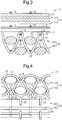
Fig. 3 is a cross-sectional view taken along line 3-3 ofFig. 1 . -
Fig. 4 is a partial front view of the fiber structure according to the first embodiment. -
Fig. 5 is a partial diagrammatic perspective view of a fiber structure according to a second embodiment of the present invention. -
Fig. 6 is a cross-sectional view taken along line 6-6 ofFig. 5 . -
Fig. 7 is a cross-sectional view taken along line 7-7 ofFig. 5 . -
Fig. 8 is a partial front view of the fiber structure according to the second embodiment. -
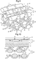
Fig. 9 is a partial diagrammatic perspective view of a fiber structure according to a third embodiment of the present invention. -
Fig. 10 is a cross-sectional view taken along line 10-10 ofFig. 9 . -
Fig. 11 is a cross-sectional view taken along line 11-11 ofFig. 9 . -
Fig. 12 is a partial front view of the fiber structure according to the third embodiment. - A fiber structure according to a first embodiment of the present invention will now be described with reference to
Figs. 1 to 4 . - As shown in
Figs. 1 to 3 , afiber structure 10 is formed by stacking afirst laminate 13 and asecond laminate 20 and joining the first andsecond laminates - The
first laminate 13 is a laminate of twofirst fiber layers 14. The twofirst fiber layers 14 are joined in the stacking direction with first intermediatestructural yarns 16. - Each
first fiber layer 14 includes reinforcement fiber yarns, which are firstreinforcement fiber yarns 11 in this embodiment, auxiliary yarns, which are firstauxiliary yarns 12 in this embodiment, and first intralayerstructural yarns 15, which join the firstreinforcement fiber yarns 11 and the firstauxiliary yarns 12 in an arrangement direction. In eachfirst fiber layer 14, the firstreinforcement fiber yarns 11 and the firstauxiliary yarns 12 are arranged alternately. Additionally, in eachfirst fiber layer 14, the firstreinforcement fiber yarns 11 are arranged parallel to each other, the firstauxiliary yarns 12 are arranged parallel to each other, and the firstreinforcement fiber yarns 11 and the firstauxiliary yarns 12 are arranged parallel to each other. - In the first fiber layers 14, each first intralayer
structural yarn 15 is engaged with the upper surface or the lower surface of the firstreinforcement fiber yarns 11 and is engaged with the lower surface or the upper surface of the firstauxiliary yarns 12. Each first intralayerstructural yarn 15 extends in the arrangement direction of the firstreinforcement fiber yarns 11 and the firstauxiliary yarns 12 while being alternately folded back with respect to the firstreinforcement fiber yarns 11 and the firstauxiliary yarns 12. The term "reinforcement fiber" of the firstreinforcement fiber yarn 11 refers to a fiber bundle that reinforces the matrix of the fiber-reinforced composite when thefiber structure 10 is used as the reinforced base material of the fiber-reinforced composite. The firstreinforcement fiber yarns 11 have the same thickness. The firstauxiliary yarns 12 are fiber bundles thinner than the firstreinforcement fiber yarns 11. - As shown in
Figs. 1 and4 , the two first fiber layers 14 of thefirst laminate 13 are stacked and joined together in the stacking direction with the first intermediatestructural yarns 16. - As shown in
Figs. 2 and3 , each first intermediatestructural yarn 16 is arranged between the first intralayerstructural yarns 15 that are adjacent to each other in the direction of the yarn main axis of the firstreinforcement fiber yarns 11, and the first intermediatestructural yarns 16 are arranged parallel to each other. As shown inFig. 4 , each first intermediatestructural yarn 16 is engaged with the upper surface of one of the firstauxiliary yarns 12 of the upperfirst fiber layer 14 located on one end in the stacking direction, is folded back, and then extends in the stacking direction. Subsequently, each first intermediatestructural yarn 16 is engaged with the lower surface of one of the second intermediatestructural yarns 26 below one of the firstauxiliary yarns 12 of the lowerfirst fiber layer 14 located on the other end in the stacking direction and is then folded back. Each first intermediatestructural yarn 16 extends in the arrangement direction while repeating engagement with the firstauxiliary yarns 12 and the second intermediatestructural yarns 26. This joins the two first fiber layers 14 in the stacking direction. - In the
first laminate 13, the firstreinforcement fiber yarns 11 are arranged to partially overlap each other in the width direction of the firstreinforcement fiber yarns 11 in the plan view. Additionally, in thefirst laminate 13, the firstreinforcement fiber yarns 11 are arranged in a staggered manner by shifting the relative positions of the firstreinforcement fiber yarns 11 in the stacking direction. Furthermore, in thefirst laminate 13, the firstauxiliary yarns 12 are also arranged in a staggered manner by shifting the relative positions of the firstauxiliary yarns 12 in the stacking direction. - As shown in
Figs. 1 to 3 , thesecond laminate 20 is a laminate of two second fiber layers 24 and is formed by joining the two second fiber layers 24 in the stacking direction with second intermediatestructural yarns 26. - Each
second fiber layer 24 includes reinforcement fiber yarns, which are secondreinforcement fiber yarns 21 in this embodiment, auxiliary yarns, which are secondauxiliary yarns 22 in this embodiment, and second intralayerstructural yarns 25, which join the secondreinforcement fiber yarns 21 and the secondauxiliary yarns 22 in the arrangement direction. In eachsecond fiber layer 24, the secondreinforcement fiber yarns 21 and the secondauxiliary yarns 22 are arranged alternately. Additionally, in eachsecond fiber layer 24, the secondreinforcement fiber yarns 21 are arranged parallel to each other, the secondauxiliary yarns 22 are arranged parallel to each other, and the secondreinforcement fiber yarns 21 and the secondauxiliary yarns 22 are arranged parallel to each other. - In the second fiber layers 24, each second intralayer
structural yarn 25 is engaged with the upper surface or the lower surface of the secondreinforcement fiber yarns 21 and is engaged with the lower surface or the upper surface of the secondauxiliary yarns 22. Each second intralayerstructural yarn 25 extends in the arrangement direction of the secondreinforcement fiber yarns 21 and the secondauxiliary yarns 22 while being alternately folded back with respect to the secondreinforcement fiber yarns 21 and the secondauxiliary yarns 22. The secondreinforcement fiber yarns 21 are the same yarns as the firstreinforcement fiber yarns 11, and the secondauxiliary yarns 22 are the same yarns as the firstauxiliary yarns 12. - As shown in
Figs. 3 and 4 , the two second fiber layers 24 of thesecond laminate 20 are stacked and joined together in the stacking direction with the second intermediatestructural yarns 26. Each second intermediatestructural yarn 26 is arranged between the second intralayerstructural yarns 25 that are adjacent to each other in the direction of the yarn main axis of the secondreinforcement fiber yarns 21, and the second intermediatestructural yarns 26 are arranged parallel to each other. Each second intermediatestructural yarn 26 is engaged with the upper surface of one of the first intermediatestructural yarns 16 above one of the secondauxiliary yarns 22 of the uppersecond fiber layer 24 located on one end in the stacking direction, is folded back, and then extends in the stacking direction. Subsequently, each second intermediatestructural yarn 26 is engaged with the lower surface of one of the secondauxiliary yarns 22 of the lowersecond fiber layer 24 located on the other end in the stacking direction and is then folded back. Each second intermediatestructural yarn 26 extends in the arrangement direction while repeating engagement with the first intermediatestructural yarns 16 and the secondauxiliary yarns 22. This joins the two second fiber layers 24 together in the stacking direction. - In the
second laminate 20, the secondreinforcement fiber yarns 21 are arranged to partially overlap each other in the width direction of the secondreinforcement fiber yarns 21 in the plan view. Additionally, in thesecond laminate 20, the secondreinforcement fiber yarns 21 are arranged in a staggered manner by shifting the relative positions of the secondreinforcement fiber yarns 21 in the stacking direction. Furthermore, in thesecond laminate 20, the secondauxiliary yarns 22 are also arranged in a staggered manner by shifting the relative positions of the secondauxiliary yarns 22 in the stacking direction. - As shown in
Fig. 1 , the direction of the yarn main axis of the firstreinforcement fiber yarns 11 in thefirst laminate 13 is defined as a first yarn main axis direction Y1. The orientation angle of the firstreinforcement fiber yarns 11 is defined as 0 degrees. The direction of the yarn main axis of the secondreinforcement fiber yarns 21 in thesecond laminate 20 is defined as a second yarn main axis direction Y2. The yarn main axis of the firstreinforcement fiber yarns 11 in thefirst laminate 13 intersects the yarn main axis of the secondreinforcement fiber yarns 21 in thesecond laminate 20 at 90 degrees, that is, the yarn main axis of the firstreinforcement fiber yarns 11 in thefirst laminate 13 is orthogonal to the yarn main axis of the secondreinforcement fiber yarns 21 in thesecond laminate 20. Thefiber structure 10 has a biaxial fiber structure of 0 degrees and 90 degrees. In thefiber structure 10, thefirst laminate 13, in which the yarn main axis of the firstreinforcement fiber yarns 11 extends in one direction (the first yarn main axis direction Y1), and thesecond laminate 20, in which the yarn main axis of the secondreinforcement fiber yarns 21 extends in the other direction (the second yarn main axis direction Y2), are joined together in the stacking direction. Thefirst laminate 13 and thesecond laminate 20 are joined together in the stacking direction by the engagement between the first intermediatestructural yarns 16 of thefirst laminate 13 and the second intermediatestructural yarns 26 of thesecond laminate 20. - As shown in
Figs. 3 and 4 , each first intermediatestructural yarn 16 of thefirst laminate 13 extends to a position between the firstreinforcement fiber yarns 11 of the lowerfirst fiber layer 14 and thesecond laminate 20 and is folded back. Each second intermediatestructural yarn 26 of thesecond laminate 20 extends to a position between the secondreinforcement fiber yarns 21 of the uppersecond fiber layer 24 and thefirst laminate 13 and is folded back. Each first intermediatestructural yarn 16 of thefirst laminate 13 is orthogonal to and engaged with the second intermediatestructural yarns 26 of thesecond laminate 20 at positions between thelaminates - The above-described
fiber structure 10 is shaped and preformed. Subsequently, thefiber structure 10 is impregnated with a liquid thermosetting resin (matrix) by, for example, a resin transfer molding (RTM) method and the liquid thermosetting resin is cured to form the fiber-reinforced composite. - Operation of the
fiber structure 10 will now be described. - The
first laminate 13 and thesecond laminate 20 of thefiber structure 10 are joined together in the stacking direction using the first intermediatestructural yarns 16 of thefirst laminate 13 and the second intermediatestructural yarns 26 of thesecond laminate 20. - The above-described embodiment achieves the following advantages.
- (1) When the
fiber structure 10 is produced using a loom, the manner in which the first intermediatestructural yarns 16 and the second intermediatestructural yarns 26 are fed is controlled to engage the first intermediatestructural yarns 16 with the second intermediatestructural yarns 26. The engagement joins thefirst laminate 13 and thesecond laminate 20 together in the stacking direction. This allows for easy production using the loom, of thebiaxial fiber structure 10, in which the yarn main axis of the firstreinforcement fiber yarns 11 in the first laminate 13 (the first yarn main axis direction Y1) is orthogonal to the yarn main axis of the secondreinforcement fiber yarns 21 in the second laminate 20 (the second yarn main axis direction Y2). Consequently, thebiaxial fiber structure 10 is easily produced compared with, for example, a method in which thefirst laminate 13 and thesecond laminate 20 are separately produced, and thefirst laminate 13 and thesecond laminate 20 are joined in the stacking direction using separate yarns in the subsequent process. - (2) In the
fiber structure 10, the firstreinforcement fiber yarns 11 and the secondreinforcement fiber yarns 21 extend straight and do not curve or bend. This prevents a decrease in the dynamic property in the first yarn main axis direction Y1 and the second yarn main axis direction Y2 of the fiber-reinforced composite that includes thefiber structure 10 as the reinforced base material. - (3) The first intermediate
structural yarns 16 of thefirst laminate 13 join the two first fiber layers 14 of thefirst laminate 13 together in the stacking direction. The second intermediatestructural yarns 26 of thesecond laminate 20 join the two second fiber layers 24 of thesecond laminate 20 in the stacking direction. Thus, the intermediatestructural yarns - (4) The fiber layers 14 of the
first laminate 13 can be joined together by the engagement between theauxiliary yarns 12 of the fiber layers 14 and the intermediatestructural yarns 16. The the fiber layers 24 of thesecond laminate 20 can be joined together by the engagement between theauxiliary yarns 22 of the fiber layers 24 and the intermediatestructural yarns 26. Thefirst laminate 13 and thesecond laminate 20 can be joined together in the stacking direction by the engagement between the first intermediatestructural yarns 16 and the second intermediatestructural yarns 26. That is, the laminates and the fiber layers of thefiber structure 10 can be joined together in the stacking direction by the engagement between the yarns other than the firstreinforcement fiber yarns 11 and the secondreinforcement fiber yarns 21. This prevents the firstreinforcement fiber yarns 11 and the secondreinforcement fiber yarns 21 from bending or curving due to the joining of the laminates and the fiber layers of thefiber structure 10 in the stacking direction. Thus, the dynamic property in the yarn main axis directions Y1, Y2 of the fiber-reinforced composite that uses thefiber structure 10 is not decreased. - A
fiber structure 10 according to a second embodiment will now be described with reference toFigs. 5 to 8 . The detailed description of the configuration of the second embodiment that is the same as the first embodiment will be omitted. - As shown in
Fig. 5 , in thefiber structure 10 according to the second embodiment, thefirst laminate 13 and thesecond laminate 20 are joined together in the stacking direction by the engagement between the first intralayerstructural yarns 15 of thefirst laminate 13 and the second intralayerstructural yarns 25 of thesecond laminate 20. - As shown in
Figs. 6 and7 , the first intralayerstructural yarns 15 of one of the first fiber layers 14 of thefirst laminate 13 that is located close to thesecond laminate 20 is defined as first engaging intralayerstructural yarns 15a. The second intralayerstructural yarns 25 of one of the second fiber layers 24 of thesecond laminate 20 that is located close to thefirst laminate 13 is defined as second engaging intralayerstructural yarns 25a. - In the vicinity of the boundary between the
first laminate 13 and thesecond laminate 20, each second engaging intralayerstructural yarn 25a engages with the first engaging intralayerstructural yarns 15a from above and engages with the secondauxiliary yarns 22 that are adjacent in the arrangement direction from below. The first engaging intralayerstructural yarns 15a are located above the secondreinforcement fiber yarns 21 of thesecond fiber layer 24. With this configuration, the second engaging intralayerstructural yarns 25a join the secondreinforcement fiber yarns 21 of thesecond fiber layer 24 in the arrangement direction together with the first engaging intralayerstructural yarns 15a. - As shown in
Fig. 8 , in thefirst laminate 13, the two first fiber layers 14 are joined together in the stacking direction with the first intermediatestructural yarns 16. In thesecond laminate 20, the two second fiber layers 24 are joined together in the stacking direction with the second intermediatestructural yarns 26. Thefirst laminate 13 and thesecond laminate 20 are joined together in the stacking direction by the engagement between the first engaging intralayerstructural yarns 15a and the second engaging intralayerstructural yarns 25a. - In addition to the advantages (1) and (2) of the first embodiment, the second embodiment achieves the following advantage.
- (5) In the vicinity of the boundary between the
first laminate 13 and thesecond laminate 20, thefirst fiber layer 14 and thesecond fiber layer 24 that are adjacent in the stacking direction are joined together with each other using the engaging intralayerstructural yarns first laminate 13 and thesecond laminate 20 are joined together at a position close to each other in the stacking direction. Thus, the first andsecond laminates - A
fiber structure 10 according to a third embodiment will now be described with reference toFigs. 9 to 12 . The detailed description of the configuration of the third embodiment that is the same as the first embodiment will be omitted. - As shown in
Figs. 9 and12 , in thefiber structure 10 according to the third embodiment, thefirst laminate 13 and thesecond laminate 20 are joined together in the stacking direction by the engagement between the first intralayerstructural yarns 15 and the second intralayerstructural yarns 25 and the engagement between the first intermediatestructural yarns 16 and the second intermediatestructural yarns 26. - As shown in
Figs. 10 and11 , the first intralayerstructural yarns 15 of one of the first fiber layers 14 of thefirst laminate 13 that is located close to thesecond laminate 20 is defined as the first engaging intralayerstructural yarns 15a. The second intralayerstructural yarns 25 of one of the second fiber layers 24 of thesecond laminate 20 that is located close to thefirst laminate 13 is defined as the second engaging intralayerstructural yarns 25a. - As shown in
Figs. 9 and12 , in the vicinity of the boundary between thefirst laminate 13 and thesecond laminate 20, each second engaging intralayerstructural yarn 25a engages with the first engaging intralayerstructural yarns 15a from above and engages with the secondauxiliary yarns 22 that are adjacent in the arrangement direction from below. The first engaging intralayerstructural yarns 15a are located above the secondreinforcement fiber yarns 21 of thesecond fiber layer 24. With this configuration, the second engaging intralayerstructural yarns 25a join the secondreinforcement fiber yarns 21 of thesecond fiber layer 24 in the arrangement direction together with the first engaging intralayerstructural yarns 15a. - Each first intermediate
structural yarn 16 of thefirst laminate 13 extends to a position between the firstreinforcement fiber yarns 11 of the lowerfirst fiber layer 14 and thesecond laminate 20 and is folded back. Each second intermediatestructural yarn 26 of thesecond laminate 20 extends to a position between the secondreinforcement fiber yarns 21 of the uppersecond fiber layer 24 and thefirst laminate 13 and is folded back. Each first intermediatestructural yarn 16 of thefirst laminate 13 is orthogonal to and engaged with the second intermediatestructural yarns 26 of thesecond laminate 20 at positions between thelaminates - In addition to the advantages (1) and (2) of the first embodiment, the third embodiment achieves the following advantage.
- (6) The
first laminate 13 and thesecond laminate 20 are joined together in the stacking direction by the engagement between the intralayerstructural yarns structural yarns first laminate 13 and thesecond laminate 20 in the stacking direction. - The above described embodiments may be modified as follows.
- In the first embodiment, the engaging position of the second intralayer
structural yarns 25 with respect to the secondauxiliary yarns 22 and the secondreinforcement fiber yarns 21 in thesecond laminate 20 may be opposite to the position in the first embodiment. Specifically, the second intralayerstructural yarns 25 may be engaged with the upper surface of the secondauxiliary yarns 22 and engaged with the lower surface of the secondreinforcement fiber yarns 21. That is, the second intralayerstructural yarns 25 may be located at positions not facing the first intralayerstructural yarns 15 in the stacking direction. The second intralayerstructural yarns 25 of one of the second fiber layers 24 of thesecond laminate 20 that is located close to thefirst laminate 13 are referred to as the second engaging intralayerstructural yarns 25a. - The
first laminate 13 and thesecond laminate 20 may be joined together in the stacking direction by the engagement between the first intermediatestructural yarns 16 of thefirst laminate 13 and the second engaging intralayerstructural yarns 25a of thesecond laminate 20. Furthermore, thefirst laminate 13 and thesecond laminate 20 may be joined together in the stacking direction by the engagement between the first engaging intralayerstructural yarns 15a of thefirst laminate 13 and the second intermediatestructural yarns 26 of thesecond laminate 20. - The
first laminate 13 and thesecond laminate 20 may be joined together by the engagement between the first engaging intralayerstructural yarns 15a of thefirst laminate 13 and the second engaging intralayerstructural yarns 25a of thesecond laminate 20 and the engagement between the first engaging intralayerstructural yarns 15a of thefirst laminate 13 and the second intermediatestructural yarns 26 of thesecond laminate 20. - Furthermore, the
first laminate 13 and thesecond laminate 20 may be joined together by the engagement between the first intermediatestructural yarns 16 of thefirst laminate 13 and the second intermediatestructural yarns 26 of thesecond laminate 20 and the engagement between the first intermediatestructural yarns 16 of thefirst laminate 13 and the second engaging intralayerstructural yarns 25a of thesecond laminate 20. - Moreover, the
first laminate 13 and thesecond laminate 20 may be joined together by the engagement between the first intermediatestructural yarns 16 of thefirst laminate 13 and the second intermediatestructural yarns 26 of thesecond laminate 20 and the engagement between the first engaging intralayerstructural yarns 15a of thefirst laminate 13 and the second intermediatestructural yarns 26 of thesecond laminate 20. - Additionally, the
first laminate 13 and thesecond laminate 20 may be joined together by the engagement between the first intermediatestructural yarns 16 of thefirst laminate 13 and the second engaging intralayerstructural yarns 25a of thesecond laminate 20 and the engagement between the first engaging intralayerstructural yarns 15a of thefirst laminate 13 and the second engaging intralayerstructural yarns 25a of thesecond laminate 20. - The number of the fiber layers constituting the first and
second laminates - The
fiber structure 10 may be constituted by stacking three or more laminates. - The cross-sectional shape and the thickness of the first
reinforcement fiber yarns 11 and the secondreinforcement fiber yarns 21 may be changed as required. - When the
fiber structure 10 is used as the reinforced base material of the fiber-reinforced composite, the kind of the matrix resin and the method for producing the fiber-reinforced composite are not limited to any particular resin or method. - The fiber bundles constituting the first
reinforcement fiber yarns 11 and the secondreinforcement fiber yarns 21 may be high-strength organic fiber such as aramid fiber, poly-p-phenylenebenzobisoxazole fiber, and ultra-high-molecular-weight polyethylene fiber or inorganic fiber such as glass fiber and ceramic fiber in accordance with the physical properties required for the fiber-reinforced composite.
Claims (6)
- A fiber structure comprising a plurality of laminates, wherein
the laminates each include a plurality of stacked fiber layers,
the fiber layers each include reinforcement fiber yarns, auxiliary yarns, and intralayer structural yarns, the reinforcement fiber yarns and the auxiliary yarns being arranged alternately, and the intralayer structural yarns joining the reinforcement fiber yarns and the auxiliary yarns together in an arrangement direction,
in each laminate,yarn main axis directions of the reinforcement fiber yarns and the auxiliary yarns of each of the fiber layers are the same,the reinforcement fiber yarns are arranged in such a manner that the relative positions are shifted in a stacking direction of the fiber layers with the reinforcement fiber yarns overlapping each other,the auxiliary yarns are arranged in such a manner that the relative positions are shifted, andthe fiber layers are joined with intermediate structural yarns engaged with the auxiliary yarns located on opposite ends in the stacking direction,the laminates are arranged such thata yarn main axis of the reinforcement fiber yarns of each laminate is orthogonal to a yarn main axis of the reinforcement fiber yarns of another laminate, anda yarn main axis of the auxiliary yarns of each laminate is orthogonal to a yarn main axis of the auxiliary yarns of another laminate, andthe laminates are joined together in the stacking direction by an engagement between at least one of a set of the intralayer structural yarns and a set of the intermediate structural yarns of the laminate in which the yarn main axis extends in one direction and at least one of a set of the intralayer structural yarns and a set of the intermediate structural yarns of the laminate in which the yarn main axis extends in another direction. - The fiber structure according to claim 1, wherein the laminates are joined together by the engagement between the intermediate structural yarns of the laminate in which the yarn main axis extends in one direction and the intermediate structural yarns of the laminate in which the yarn main axis extends in another direction.
- The fiber structure according to claim 1, wherein the laminates are joined together by the engagement between the intralayer structural yarns of the laminate in which the yarn main axis extends in one direction and the intralayer structural yarns of the laminate in which the yarn main axis extends in another direction.
- The fiber structure according to claim 1, wherein the laminates are joined together by
the engagement between the intermediate structural yarns of the laminate in which the yarn main axis extends in one direction and the intermediate structural yarns of the laminate in which the yarn main axis extends in another direction, and
the engagement between the intralayer structural yarns of the laminate in which the yarn main axis extends in one direction and the intralayer structural yarns of the laminate in which the yarn main axis extends in another direction. - The fiber structure according to any one of claims 1 to 4, wherein each of the intermediate structural yarns is arranged between the intralayer structural yarns located adjacent to each other in the yarn main axis direction of the reinforcement fiber yarns and the auxiliary yarns.
- A fiber-reinforced composite in which a fiber structure is impregnated with a matrix resin, wherein
the fiber structure includes a plurality of laminates,
the laminates each include a plurality of stacked fiber layers,
the fiber layers each include reinforcement fiber yarns, auxiliary yarns, and intralayer structural yarns, the reinforcement fiber yarns and the auxiliary yarns being arranged alternately, and the intralayer structural yarns joining the reinforcement fiber yarns and the auxiliary yarns together in an arrangement direction,
in each laminate,yarn main axis directions of the reinforcement fiber yarns and the auxiliary yarns of each of the fiber layers are the same,the reinforcement fiber yarns are arranged in such a manner that the relative positions are shifted in a stacking direction of the fiber layers with the reinforcement fiber yarns overlapping each other,the auxiliary yarns are arranged in such a manner that the relative positions are shifted, andthe fiber layers are joined with intermediate structural yarns engaged with the auxiliary yarns located on opposite ends in the stacking direction,the laminates are arranged such thata yarn main axis of the reinforcement fiber yarns of each laminate is orthogonal to a yarn main axis of the reinforcement fiber yarns of another laminate, anda yarn main axis of the auxiliary yarns of each laminate is orthogonal to a yarn main axis of the auxiliary yarns of another laminate, andthe laminates are joined together in the stacking direction by an engagement between at least one of a set of the intralayer structural yarns and a set of the intermediate structural yarns of the laminate in which the yarn main axis extends in one direction and at least one of a set of the intralayer structural yarns and a set of the intermediate structural yarns of the laminate in which the yarn main axis extends in another direction.
Applications Claiming Priority (2)
| Application Number | Priority Date | Filing Date | Title |
|---|---|---|---|
| JP2015220394A JP6528651B2 (en) | 2015-11-10 | 2015-11-10 | Fiber structure |
| PCT/JP2016/081859 WO2017082066A1 (en) | 2015-11-10 | 2016-10-27 | Fiber structure |
Publications (3)
| Publication Number | Publication Date |
|---|---|
| EP3375920A1 true EP3375920A1 (en) | 2018-09-19 |
| EP3375920A4 EP3375920A4 (en) | 2018-10-24 |
| EP3375920B1 EP3375920B1 (en) | 2019-08-14 |
Family
ID=58696020
Family Applications (1)
| Application Number | Title | Priority Date | Filing Date |
|---|---|---|---|
| EP16864030.8A Not-in-force EP3375920B1 (en) | 2015-11-10 | 2016-10-27 | Fiber structure |
Country Status (6)
| Country | Link |
|---|---|
| US (1) | US20180313005A1 (en) |
| EP (1) | EP3375920B1 (en) |
| JP (1) | JP6528651B2 (en) |
| CN (1) | CN108350621B (en) |
| ES (1) | ES2751063T3 (en) |
| WO (1) | WO2017082066A1 (en) |
Families Citing this family (2)
| Publication number | Priority date | Publication date | Assignee | Title |
|---|---|---|---|---|
| JP7666397B2 (en) * | 2022-05-13 | 2025-04-22 | 株式会社豊田自動織機 | Fiber structure for fiber-reinforced composite material and fiber-reinforced composite material |
| JP7845244B2 (en) * | 2023-03-20 | 2026-04-14 | 株式会社豊田自動織機 | Fiber structures and fiber-reinforced composites |
Family Cites Families (7)
| Publication number | Priority date | Publication date | Assignee | Title |
|---|---|---|---|---|
| JPH072194Y2 (en) * | 1989-10-31 | 1995-01-25 | ユニチカユーエムグラス株式会社 | Laminated cloth |
| JPH04135986U (en) * | 1991-06-10 | 1992-12-17 | 鐘紡株式会社 | Fiber structures for composite materials |
| JP2009249754A (en) * | 2008-04-03 | 2009-10-29 | Mitsubishi Rayon Co Ltd | Reinforcing fiber woven fabric and method for weaving the same |
| JP5644755B2 (en) * | 2011-12-26 | 2014-12-24 | 株式会社豊田自動織機 | Textile substrate and fiber reinforced composite material |
| WO2013035518A1 (en) * | 2011-09-08 | 2013-03-14 | 株式会社 豊田自動織機 | Woven fabric base material and fiber-reinforced composite material |
| US9415566B2 (en) * | 2012-08-21 | 2016-08-16 | Kabushiki Kaisha Toyota Jidoshokki | Three-dimensional fiber-reinforced composite material |
| US9539789B2 (en) * | 2012-08-21 | 2017-01-10 | Kabushiki Kaisha Toyota Jidoshokki | Three-dimensional fiber-reinforced composite and method for producing three-dimensional fiber-reinforced composite |
-
2015
- 2015-11-10 JP JP2015220394A patent/JP6528651B2/en not_active Expired - Fee Related
-
2016
- 2016-10-27 WO PCT/JP2016/081859 patent/WO2017082066A1/en not_active Ceased
- 2016-10-27 CN CN201680063790.5A patent/CN108350621B/en not_active Expired - Fee Related
- 2016-10-27 ES ES16864030T patent/ES2751063T3/en active Active
- 2016-10-27 US US15/771,153 patent/US20180313005A1/en not_active Abandoned
- 2016-10-27 EP EP16864030.8A patent/EP3375920B1/en not_active Not-in-force
Also Published As
| Publication number | Publication date |
|---|---|
| CN108350621A (en) | 2018-07-31 |
| EP3375920A4 (en) | 2018-10-24 |
| CN108350621B (en) | 2019-11-15 |
| US20180313005A1 (en) | 2018-11-01 |
| JP2017089053A (en) | 2017-05-25 |
| WO2017082066A1 (en) | 2017-05-18 |
| ES2751063T3 (en) | 2020-03-30 |
| JP6528651B2 (en) | 2019-06-12 |
| EP3375920B1 (en) | 2019-08-14 |
Similar Documents
| Publication | Publication Date | Title |
|---|---|---|
| JP5617788B2 (en) | Fiber reinforced composite material | |
| KR101422653B1 (en) | Hybrid three-dimensional woven/laminated structure for composite structural applications | |
| AU2013221734B2 (en) | Pi-shaped preform with bias fibers | |
| EP3375920B1 (en) | Fiber structure | |
| US9840062B2 (en) | Fiber-reinforced composite material | |
| US20210180221A1 (en) | Fiber construct, fiber-reinforced composite material, and method for manufacturing these | |
| US9415566B2 (en) | Three-dimensional fiber-reinforced composite material | |
| JP6493094B2 (en) | Fiber structure and fiber reinforced composite | |
| US10947647B2 (en) | Fabric for fiber reinforced composite material and fiber reinforced composite material | |
| WO2019012983A1 (en) | Fiber structure and fiber-reinforced composite material | |
| JP5644755B2 (en) | Textile substrate and fiber reinforced composite material | |
| US10544525B2 (en) | Fibrous structure and fiber-reinforced composite material | |
| JP7287162B2 (en) | Fiber structures and fiber reinforced composites | |
| WO2012014613A1 (en) | Fiber substrate and fiber-reinforced composite material | |
| US20170137982A1 (en) | Nonwoven | |
| KR102401275B1 (en) | Fiber reinforced composite material having a hollow section and methode for manufacturing the same | |
| KR20230153126A (en) | Continuous fiber reinforced thermoplastic composite and the manufacturing the same | |
| JP2014004735A (en) | Fiber-reinforced composite material and method of producing fiber-reinforced composite material | |
| JP2014047432A (en) | Three-dimensional fiber structure |
Legal Events
| Date | Code | Title | Description |
|---|---|---|---|
| STAA | Information on the status of an ep patent application or granted ep patent |
Free format text: STATUS: THE INTERNATIONAL PUBLICATION HAS BEEN MADE |
|
| PUAI | Public reference made under article 153(3) epc to a published international application that has entered the european phase |
Free format text: ORIGINAL CODE: 0009012 |
|
| STAA | Information on the status of an ep patent application or granted ep patent |
Free format text: STATUS: REQUEST FOR EXAMINATION WAS MADE |
|
| 17P | Request for examination filed |
Effective date: 20180419 |
|
| AK | Designated contracting states |
Kind code of ref document: A1 Designated state(s): AL AT BE BG CH CY CZ DE DK EE ES FI FR GB GR HR HU IE IS IT LI LT LU LV MC MK MT NL NO PL PT RO RS SE SI SK SM TR |
|
| AX | Request for extension of the european patent |
Extension state: BA ME |
|
| REG | Reference to a national code |
Ref country code: DE Ref legal event code: R079 Ref document number: 602016018809 Country of ref document: DE Free format text: PREVIOUS MAIN CLASS: D03D0001000000 Ipc: D03D0011000000 |
|
| A4 | Supplementary search report drawn up and despatched |
Effective date: 20180925 |
|
| RIC1 | Information provided on ipc code assigned before grant |
Ipc: D03D 11/00 20060101AFI20180919BHEP |
|
| DAV | Request for validation of the european patent (deleted) | ||
| DAX | Request for extension of the european patent (deleted) | ||
| GRAP | Despatch of communication of intention to grant a patent |
Free format text: ORIGINAL CODE: EPIDOSNIGR1 |
|
| STAA | Information on the status of an ep patent application or granted ep patent |
Free format text: STATUS: GRANT OF PATENT IS INTENDED |
|
| INTG | Intention to grant announced |
Effective date: 20190313 |
|
| GRAS | Grant fee paid |
Free format text: ORIGINAL CODE: EPIDOSNIGR3 |
|
| GRAA | (expected) grant |
Free format text: ORIGINAL CODE: 0009210 |
|
| STAA | Information on the status of an ep patent application or granted ep patent |
Free format text: STATUS: THE PATENT HAS BEEN GRANTED |
|
| AK | Designated contracting states |
Kind code of ref document: B1 Designated state(s): AL AT BE BG CH CY CZ DE DK EE ES FI FR GB GR HR HU IE IS IT LI LT LU LV MC MK MT NL NO PL PT RO RS SE SI SK SM TR |
|
| REG | Reference to a national code |
Ref country code: GB Ref legal event code: FG4D |
|
| REG | Reference to a national code |
Ref country code: CH Ref legal event code: EP Ref country code: AT Ref legal event code: REF Ref document number: 1167155 Country of ref document: AT Kind code of ref document: T Effective date: 20190815 |
|
| REG | Reference to a national code |
Ref country code: IE Ref legal event code: FG4D |
|
| REG | Reference to a national code |
Ref country code: DE Ref legal event code: R096 Ref document number: 602016018809 Country of ref document: DE |
|
| REG | Reference to a national code |
Ref country code: NL Ref legal event code: FP |
|
| REG | Reference to a national code |
Ref country code: SE Ref legal event code: TRGR |
|
| REG | Reference to a national code |
Ref country code: LT Ref legal event code: MG4D |
|
| PG25 | Lapsed in a contracting state [announced via postgrant information from national office to epo] |
Ref country code: PT Free format text: LAPSE BECAUSE OF FAILURE TO SUBMIT A TRANSLATION OF THE DESCRIPTION OR TO PAY THE FEE WITHIN THE PRESCRIBED TIME-LIMIT Effective date: 20191216 Ref country code: NO Free format text: LAPSE BECAUSE OF FAILURE TO SUBMIT A TRANSLATION OF THE DESCRIPTION OR TO PAY THE FEE WITHIN THE PRESCRIBED TIME-LIMIT Effective date: 20191114 Ref country code: BG Free format text: LAPSE BECAUSE OF FAILURE TO SUBMIT A TRANSLATION OF THE DESCRIPTION OR TO PAY THE FEE WITHIN THE PRESCRIBED TIME-LIMIT Effective date: 20191114 Ref country code: LT Free format text: LAPSE BECAUSE OF FAILURE TO SUBMIT A TRANSLATION OF THE DESCRIPTION OR TO PAY THE FEE WITHIN THE PRESCRIBED TIME-LIMIT Effective date: 20190814 Ref country code: HR Free format text: LAPSE BECAUSE OF FAILURE TO SUBMIT A TRANSLATION OF THE DESCRIPTION OR TO PAY THE FEE WITHIN THE PRESCRIBED TIME-LIMIT Effective date: 20190814 Ref country code: FI Free format text: LAPSE BECAUSE OF FAILURE TO SUBMIT A TRANSLATION OF THE DESCRIPTION OR TO PAY THE FEE WITHIN THE PRESCRIBED TIME-LIMIT Effective date: 20190814 |
|
| REG | Reference to a national code |
Ref country code: AT Ref legal event code: MK05 Ref document number: 1167155 Country of ref document: AT Kind code of ref document: T Effective date: 20190814 |
|
| PG25 | Lapsed in a contracting state [announced via postgrant information from national office to epo] |
Ref country code: AL Free format text: LAPSE BECAUSE OF FAILURE TO SUBMIT A TRANSLATION OF THE DESCRIPTION OR TO PAY THE FEE WITHIN THE PRESCRIBED TIME-LIMIT Effective date: 20190814 Ref country code: GR Free format text: LAPSE BECAUSE OF FAILURE TO SUBMIT A TRANSLATION OF THE DESCRIPTION OR TO PAY THE FEE WITHIN THE PRESCRIBED TIME-LIMIT Effective date: 20191115 Ref country code: IS Free format text: LAPSE BECAUSE OF FAILURE TO SUBMIT A TRANSLATION OF THE DESCRIPTION OR TO PAY THE FEE WITHIN THE PRESCRIBED TIME-LIMIT Effective date: 20191214 Ref country code: RS Free format text: LAPSE BECAUSE OF FAILURE TO SUBMIT A TRANSLATION OF THE DESCRIPTION OR TO PAY THE FEE WITHIN THE PRESCRIBED TIME-LIMIT Effective date: 20190814 Ref country code: LV Free format text: LAPSE BECAUSE OF FAILURE TO SUBMIT A TRANSLATION OF THE DESCRIPTION OR TO PAY THE FEE WITHIN THE PRESCRIBED TIME-LIMIT Effective date: 20190814 |
|
| REG | Reference to a national code |
Ref country code: ES Ref legal event code: FG2A Ref document number: 2751063 Country of ref document: ES Kind code of ref document: T3 Effective date: 20200330 |
|
| PG25 | Lapsed in a contracting state [announced via postgrant information from national office to epo] |
Ref country code: TR Free format text: LAPSE BECAUSE OF FAILURE TO SUBMIT A TRANSLATION OF THE DESCRIPTION OR TO PAY THE FEE WITHIN THE PRESCRIBED TIME-LIMIT Effective date: 20190814 |
|
| PG25 | Lapsed in a contracting state [announced via postgrant information from national office to epo] |
Ref country code: RO Free format text: LAPSE BECAUSE OF FAILURE TO SUBMIT A TRANSLATION OF THE DESCRIPTION OR TO PAY THE FEE WITHIN THE PRESCRIBED TIME-LIMIT Effective date: 20190814 Ref country code: DK Free format text: LAPSE BECAUSE OF FAILURE TO SUBMIT A TRANSLATION OF THE DESCRIPTION OR TO PAY THE FEE WITHIN THE PRESCRIBED TIME-LIMIT Effective date: 20190814 Ref country code: PL Free format text: LAPSE BECAUSE OF FAILURE TO SUBMIT A TRANSLATION OF THE DESCRIPTION OR TO PAY THE FEE WITHIN THE PRESCRIBED TIME-LIMIT Effective date: 20190814 Ref country code: AT Free format text: LAPSE BECAUSE OF FAILURE TO SUBMIT A TRANSLATION OF THE DESCRIPTION OR TO PAY THE FEE WITHIN THE PRESCRIBED TIME-LIMIT Effective date: 20190814 Ref country code: EE Free format text: LAPSE BECAUSE OF FAILURE TO SUBMIT A TRANSLATION OF THE DESCRIPTION OR TO PAY THE FEE WITHIN THE PRESCRIBED TIME-LIMIT Effective date: 20190814 |
|
| PG25 | Lapsed in a contracting state [announced via postgrant information from national office to epo] |
Ref country code: MC Free format text: LAPSE BECAUSE OF FAILURE TO SUBMIT A TRANSLATION OF THE DESCRIPTION OR TO PAY THE FEE WITHIN THE PRESCRIBED TIME-LIMIT Effective date: 20190814 Ref country code: CZ Free format text: LAPSE BECAUSE OF FAILURE TO SUBMIT A TRANSLATION OF THE DESCRIPTION OR TO PAY THE FEE WITHIN THE PRESCRIBED TIME-LIMIT Effective date: 20190814 Ref country code: SK Free format text: LAPSE BECAUSE OF FAILURE TO SUBMIT A TRANSLATION OF THE DESCRIPTION OR TO PAY THE FEE WITHIN THE PRESCRIBED TIME-LIMIT Effective date: 20190814 Ref country code: SM Free format text: LAPSE BECAUSE OF FAILURE TO SUBMIT A TRANSLATION OF THE DESCRIPTION OR TO PAY THE FEE WITHIN THE PRESCRIBED TIME-LIMIT Effective date: 20190814 Ref country code: IS Free format text: LAPSE BECAUSE OF FAILURE TO SUBMIT A TRANSLATION OF THE DESCRIPTION OR TO PAY THE FEE WITHIN THE PRESCRIBED TIME-LIMIT Effective date: 20200224 |
|
| REG | Reference to a national code |
Ref country code: CH Ref legal event code: PL |
|
| REG | Reference to a national code |
Ref country code: DE Ref legal event code: R097 Ref document number: 602016018809 Country of ref document: DE |
|
| PLBE | No opposition filed within time limit |
Free format text: ORIGINAL CODE: 0009261 |
|
| STAA | Information on the status of an ep patent application or granted ep patent |
Free format text: STATUS: NO OPPOSITION FILED WITHIN TIME LIMIT |
|
| PG2D | Information on lapse in contracting state deleted |
Ref country code: IS |
|
| PG25 | Lapsed in a contracting state [announced via postgrant information from national office to epo] |
Ref country code: LU Free format text: LAPSE BECAUSE OF NON-PAYMENT OF DUE FEES Effective date: 20191027 Ref country code: LI Free format text: LAPSE BECAUSE OF NON-PAYMENT OF DUE FEES Effective date: 20191031 Ref country code: CH Free format text: LAPSE BECAUSE OF NON-PAYMENT OF DUE FEES Effective date: 20191031 |
|
| 26N | No opposition filed |
Effective date: 20200603 |
|
| REG | Reference to a national code |
Ref country code: BE Ref legal event code: MM Effective date: 20191031 |
|
| PG25 | Lapsed in a contracting state [announced via postgrant information from national office to epo] |
Ref country code: SI Free format text: LAPSE BECAUSE OF FAILURE TO SUBMIT A TRANSLATION OF THE DESCRIPTION OR TO PAY THE FEE WITHIN THE PRESCRIBED TIME-LIMIT Effective date: 20190814 Ref country code: BE Free format text: LAPSE BECAUSE OF NON-PAYMENT OF DUE FEES Effective date: 20191031 |
|
| PG25 | Lapsed in a contracting state [announced via postgrant information from national office to epo] |
Ref country code: IE Free format text: LAPSE BECAUSE OF NON-PAYMENT OF DUE FEES Effective date: 20191027 |
|
| PGFP | Annual fee paid to national office [announced via postgrant information from national office to epo] |
Ref country code: NL Payment date: 20200915 Year of fee payment: 5 |
|
| PGFP | Annual fee paid to national office [announced via postgrant information from national office to epo] |
Ref country code: SE Payment date: 20201012 Year of fee payment: 5 Ref country code: ES Payment date: 20201112 Year of fee payment: 5 |
|
| PG25 | Lapsed in a contracting state [announced via postgrant information from national office to epo] |
Ref country code: CY Free format text: LAPSE BECAUSE OF FAILURE TO SUBMIT A TRANSLATION OF THE DESCRIPTION OR TO PAY THE FEE WITHIN THE PRESCRIBED TIME-LIMIT Effective date: 20190814 |
|
| PG25 | Lapsed in a contracting state [announced via postgrant information from national office to epo] |
Ref country code: HU Free format text: LAPSE BECAUSE OF FAILURE TO SUBMIT A TRANSLATION OF THE DESCRIPTION OR TO PAY THE FEE WITHIN THE PRESCRIBED TIME-LIMIT; INVALID AB INITIO Effective date: 20161027 Ref country code: MT Free format text: LAPSE BECAUSE OF FAILURE TO SUBMIT A TRANSLATION OF THE DESCRIPTION OR TO PAY THE FEE WITHIN THE PRESCRIBED TIME-LIMIT Effective date: 20190814 |
|
| PGFP | Annual fee paid to national office [announced via postgrant information from national office to epo] |
Ref country code: IT Payment date: 20210910 Year of fee payment: 6 Ref country code: FR Payment date: 20210913 Year of fee payment: 6 |
|
| PGFP | Annual fee paid to national office [announced via postgrant information from national office to epo] |
Ref country code: GB Payment date: 20210915 Year of fee payment: 6 |
|
| PGFP | Annual fee paid to national office [announced via postgrant information from national office to epo] |
Ref country code: DE Payment date: 20210914 Year of fee payment: 6 |
|
| REG | Reference to a national code |
Ref country code: SE Ref legal event code: EUG |
|
| REG | Reference to a national code |
Ref country code: NL Ref legal event code: MM Effective date: 20211101 |
|
| PG25 | Lapsed in a contracting state [announced via postgrant information from national office to epo] |
Ref country code: MK Free format text: LAPSE BECAUSE OF FAILURE TO SUBMIT A TRANSLATION OF THE DESCRIPTION OR TO PAY THE FEE WITHIN THE PRESCRIBED TIME-LIMIT Effective date: 20190814 |
|
| PG25 | Lapsed in a contracting state [announced via postgrant information from national office to epo] |
Ref country code: SE Free format text: LAPSE BECAUSE OF NON-PAYMENT OF DUE FEES Effective date: 20211028 Ref country code: NL Free format text: LAPSE BECAUSE OF NON-PAYMENT OF DUE FEES Effective date: 20211101 |
|
| REG | Reference to a national code |
Ref country code: ES Ref legal event code: FD2A Effective date: 20230207 |
|
| PG25 | Lapsed in a contracting state [announced via postgrant information from national office to epo] |
Ref country code: ES Free format text: LAPSE BECAUSE OF NON-PAYMENT OF DUE FEES Effective date: 20211028 |
|
| REG | Reference to a national code |
Ref country code: DE Ref legal event code: R119 Ref document number: 602016018809 Country of ref document: DE |
|
| GBPC | Gb: european patent ceased through non-payment of renewal fee |
Effective date: 20221027 |
|
| PG25 | Lapsed in a contracting state [announced via postgrant information from national office to epo] |
Ref country code: FR Free format text: LAPSE BECAUSE OF NON-PAYMENT OF DUE FEES Effective date: 20221031 Ref country code: DE Free format text: LAPSE BECAUSE OF NON-PAYMENT OF DUE FEES Effective date: 20230503 |
|
| PG25 | Lapsed in a contracting state [announced via postgrant information from national office to epo] |
Ref country code: IT Free format text: LAPSE BECAUSE OF NON-PAYMENT OF DUE FEES Effective date: 20221027 Ref country code: GB Free format text: LAPSE BECAUSE OF NON-PAYMENT OF DUE FEES Effective date: 20221027 |