EP3375341A2 - Cyclonic separation apparatus - Google Patents
Cyclonic separation apparatus Download PDFInfo
- Publication number
- EP3375341A2 EP3375341A2 EP18165471.6A EP18165471A EP3375341A2 EP 3375341 A2 EP3375341 A2 EP 3375341A2 EP 18165471 A EP18165471 A EP 18165471A EP 3375341 A2 EP3375341 A2 EP 3375341A2
- Authority
- EP
- European Patent Office
- Prior art keywords
- motor
- separation apparatus
- fan
- cyclonic separation
- dirt container
- Prior art date
- Legal status (The legal status is an assumption and is not a legal conclusion. Google has not performed a legal analysis and makes no representation as to the accuracy of the status listed.)
- Granted
Links
- 238000000926 separation method Methods 0.000 title claims abstract description 161
- JTJMJGYZQZDUJJ-UHFFFAOYSA-N phencyclidine Chemical class C1CCCCN1C1(C=2C=CC=CC=2)CCCCC1 JTJMJGYZQZDUJJ-UHFFFAOYSA-N 0.000 claims abstract description 45
- 239000000463 material Substances 0.000 claims abstract description 26
- 238000001816 cooling Methods 0.000 claims description 33
- 230000000295 complement effect Effects 0.000 claims description 4
- 230000013011 mating Effects 0.000 claims description 4
- 230000004907 flux Effects 0.000 claims description 3
- 239000000428 dust Substances 0.000 description 50
- 230000037361 pathway Effects 0.000 description 19
- 238000009826 distribution Methods 0.000 description 18
- 239000002245 particle Substances 0.000 description 18
- 238000004140 cleaning Methods 0.000 description 12
- 238000004891 communication Methods 0.000 description 9
- -1 polyethylene Polymers 0.000 description 8
- 239000004698 Polyethylene Substances 0.000 description 7
- 239000013536 elastomeric material Substances 0.000 description 7
- 229920000573 polyethylene Polymers 0.000 description 7
- 239000013618 particulate matter Substances 0.000 description 6
- 238000011144 upstream manufacturing Methods 0.000 description 6
- 238000010276 construction Methods 0.000 description 5
- 238000012360 testing method Methods 0.000 description 5
- 230000008901 benefit Effects 0.000 description 4
- 239000007788 liquid Substances 0.000 description 4
- 238000000034 method Methods 0.000 description 4
- 238000011065 in-situ storage Methods 0.000 description 3
- 238000011179 visual inspection Methods 0.000 description 3
- 230000009471 action Effects 0.000 description 2
- 238000013459 approach Methods 0.000 description 2
- 230000004323 axial length Effects 0.000 description 2
- 238000013461 design Methods 0.000 description 2
- 230000000694 effects Effects 0.000 description 2
- 238000001914 filtration Methods 0.000 description 2
- 230000005484 gravity Effects 0.000 description 2
- 238000003860 storage Methods 0.000 description 2
- 238000010407 vacuum cleaning Methods 0.000 description 2
- HBBGRARXTFLTSG-UHFFFAOYSA-N Lithium ion Chemical compound [Li+] HBBGRARXTFLTSG-UHFFFAOYSA-N 0.000 description 1
- 238000007664 blowing Methods 0.000 description 1
- OJIJEKBXJYRIBZ-UHFFFAOYSA-N cadmium nickel Chemical compound [Ni].[Cd] OJIJEKBXJYRIBZ-UHFFFAOYSA-N 0.000 description 1
- 238000012937 correction Methods 0.000 description 1
- 230000007423 decrease Effects 0.000 description 1
- 230000003247 decreasing effect Effects 0.000 description 1
- 238000000151 deposition Methods 0.000 description 1
- 230000005611 electricity Effects 0.000 description 1
- 210000004209 hair Anatomy 0.000 description 1
- 229910001416 lithium ion Inorganic materials 0.000 description 1
- 239000007937 lozenge Substances 0.000 description 1
- 238000005259 measurement Methods 0.000 description 1
- 230000007246 mechanism Effects 0.000 description 1
- 229910052987 metal hydride Inorganic materials 0.000 description 1
- 238000012986 modification Methods 0.000 description 1
- 230000004048 modification Effects 0.000 description 1
- 229910052759 nickel Inorganic materials 0.000 description 1
- PXHVJJICTQNCMI-UHFFFAOYSA-N nickel Substances [Ni] PXHVJJICTQNCMI-UHFFFAOYSA-N 0.000 description 1
- 238000004806 packaging method and process Methods 0.000 description 1
- 239000004033 plastic Substances 0.000 description 1
- 229920003023 plastic Polymers 0.000 description 1
- 239000005518 polymer electrolyte Substances 0.000 description 1
- 230000002459 sustained effect Effects 0.000 description 1
- 230000007704 transition Effects 0.000 description 1
Images


Classifications
-
- A—HUMAN NECESSITIES
- A47—FURNITURE; DOMESTIC ARTICLES OR APPLIANCES; COFFEE MILLS; SPICE MILLS; SUCTION CLEANERS IN GENERAL
- A47L—DOMESTIC WASHING OR CLEANING; SUCTION CLEANERS IN GENERAL
- A47L5/00—Structural features of suction cleaners
- A47L5/12—Structural features of suction cleaners with power-driven air-pumps or air-compressors, e.g. driven by motor vehicle engine vacuum
- A47L5/22—Structural features of suction cleaners with power-driven air-pumps or air-compressors, e.g. driven by motor vehicle engine vacuum with rotary fans
- A47L5/24—Hand-supported suction cleaners
-
- A—HUMAN NECESSITIES
- A47—FURNITURE; DOMESTIC ARTICLES OR APPLIANCES; COFFEE MILLS; SPICE MILLS; SUCTION CLEANERS IN GENERAL
- A47L—DOMESTIC WASHING OR CLEANING; SUCTION CLEANERS IN GENERAL
- A47L9/00—Details or accessories of suction cleaners, e.g. mechanical means for controlling the suction or for effecting pulsating action; Storing devices specially adapted to suction cleaners or parts thereof; Carrying-vehicles specially adapted for suction cleaners
- A47L9/10—Filters; Dust separators; Dust removal; Automatic exchange of filters
- A47L9/16—Arrangement or disposition of cyclones or other devices with centrifugal action
- A47L9/1608—Cyclonic chamber constructions
-
- A—HUMAN NECESSITIES
- A47—FURNITURE; DOMESTIC ARTICLES OR APPLIANCES; COFFEE MILLS; SPICE MILLS; SUCTION CLEANERS IN GENERAL
- A47L—DOMESTIC WASHING OR CLEANING; SUCTION CLEANERS IN GENERAL
- A47L9/00—Details or accessories of suction cleaners, e.g. mechanical means for controlling the suction or for effecting pulsating action; Storing devices specially adapted to suction cleaners or parts thereof; Carrying-vehicles specially adapted for suction cleaners
- A47L9/10—Filters; Dust separators; Dust removal; Automatic exchange of filters
- A47L9/16—Arrangement or disposition of cyclones or other devices with centrifugal action
- A47L9/1616—Multiple arrangement thereof
- A47L9/1625—Multiple arrangement thereof for series flow
- A47L9/1633—Concentric cyclones
-
- A—HUMAN NECESSITIES
- A47—FURNITURE; DOMESTIC ARTICLES OR APPLIANCES; COFFEE MILLS; SPICE MILLS; SUCTION CLEANERS IN GENERAL
- A47L—DOMESTIC WASHING OR CLEANING; SUCTION CLEANERS IN GENERAL
- A47L9/00—Details or accessories of suction cleaners, e.g. mechanical means for controlling the suction or for effecting pulsating action; Storing devices specially adapted to suction cleaners or parts thereof; Carrying-vehicles specially adapted for suction cleaners
- A47L9/10—Filters; Dust separators; Dust removal; Automatic exchange of filters
- A47L9/16—Arrangement or disposition of cyclones or other devices with centrifugal action
- A47L9/1616—Multiple arrangement thereof
- A47L9/1641—Multiple arrangement thereof for parallel flow
-
- A—HUMAN NECESSITIES
- A47—FURNITURE; DOMESTIC ARTICLES OR APPLIANCES; COFFEE MILLS; SPICE MILLS; SUCTION CLEANERS IN GENERAL
- A47L—DOMESTIC WASHING OR CLEANING; SUCTION CLEANERS IN GENERAL
- A47L9/00—Details or accessories of suction cleaners, e.g. mechanical means for controlling the suction or for effecting pulsating action; Storing devices specially adapted to suction cleaners or parts thereof; Carrying-vehicles specially adapted for suction cleaners
- A47L9/10—Filters; Dust separators; Dust removal; Automatic exchange of filters
- A47L9/16—Arrangement or disposition of cyclones or other devices with centrifugal action
- A47L9/165—Construction of inlets
-
- A—HUMAN NECESSITIES
- A47—FURNITURE; DOMESTIC ARTICLES OR APPLIANCES; COFFEE MILLS; SPICE MILLS; SUCTION CLEANERS IN GENERAL
- A47L—DOMESTIC WASHING OR CLEANING; SUCTION CLEANERS IN GENERAL
- A47L9/00—Details or accessories of suction cleaners, e.g. mechanical means for controlling the suction or for effecting pulsating action; Storing devices specially adapted to suction cleaners or parts thereof; Carrying-vehicles specially adapted for suction cleaners
- A47L9/10—Filters; Dust separators; Dust removal; Automatic exchange of filters
- A47L9/16—Arrangement or disposition of cyclones or other devices with centrifugal action
- A47L9/1658—Construction of outlets
- A47L9/1666—Construction of outlets with filtering means
-
- A—HUMAN NECESSITIES
- A47—FURNITURE; DOMESTIC ARTICLES OR APPLIANCES; COFFEE MILLS; SPICE MILLS; SUCTION CLEANERS IN GENERAL
- A47L—DOMESTIC WASHING OR CLEANING; SUCTION CLEANERS IN GENERAL
- A47L9/00—Details or accessories of suction cleaners, e.g. mechanical means for controlling the suction or for effecting pulsating action; Storing devices specially adapted to suction cleaners or parts thereof; Carrying-vehicles specially adapted for suction cleaners
- A47L9/10—Filters; Dust separators; Dust removal; Automatic exchange of filters
- A47L9/16—Arrangement or disposition of cyclones or other devices with centrifugal action
- A47L9/1683—Dust collecting chambers; Dust collecting receptacles
-
- A—HUMAN NECESSITIES
- A47—FURNITURE; DOMESTIC ARTICLES OR APPLIANCES; COFFEE MILLS; SPICE MILLS; SUCTION CLEANERS IN GENERAL
- A47L—DOMESTIC WASHING OR CLEANING; SUCTION CLEANERS IN GENERAL
- A47L9/00—Details or accessories of suction cleaners, e.g. mechanical means for controlling the suction or for effecting pulsating action; Storing devices specially adapted to suction cleaners or parts thereof; Carrying-vehicles specially adapted for suction cleaners
- A47L9/28—Installation of the electric equipment, e.g. adaptation or attachment to the suction cleaner; Controlling suction cleaners by electric means
- A47L9/2868—Arrangements for power supply of vacuum cleaners or the accessories thereof
- A47L9/2884—Details of arrangements of batteries or their installation
-
- Y—GENERAL TAGGING OF NEW TECHNOLOGICAL DEVELOPMENTS; GENERAL TAGGING OF CROSS-SECTIONAL TECHNOLOGIES SPANNING OVER SEVERAL SECTIONS OF THE IPC; TECHNICAL SUBJECTS COVERED BY FORMER USPC CROSS-REFERENCE ART COLLECTIONS [XRACs] AND DIGESTS
- Y10—TECHNICAL SUBJECTS COVERED BY FORMER USPC
- Y10S—TECHNICAL SUBJECTS COVERED BY FORMER USPC CROSS-REFERENCE ART COLLECTIONS [XRACs] AND DIGESTS
- Y10S55/00—Gas separation
- Y10S55/03—Vacuum cleaner
Definitions
- the present invention relates to a cyclonic separation apparatus.
- the present invention relates to a cyclonic separation apparatus for use in vacuum cleaners.
- Vacuum cleaners are well known for collecting dust and dirt, although wet-and-dry variants which can also collect liquids are known as well.
- vacuum cleaners are intended for use in a domestic environment, although they also find uses in other environments, such as worksites or in the garden.
- they are electrically powered and therefore comprise an electric motor and a fan connected to an output shaft of the motor, an inlet for dirty air, an outlet for clean air and a collection chamber for dust, dirt and possibly also liquids.
- Electrical power for the motor may be provided by a source of mains electricity, in which case the vacuum cleaner will further comprise an electrical power cable, by a removable and replaceable battery pack, or by one or more in-built rechargeable cells, in which case the vacuum cleaner will further comprise some means, such as a jack plug or electrical contacts, for connecting the vacuum cleaner to a recharging unit.
- the electric motor drives the fan to draw dirty air along an air flow pathway in through the dirty air inlet, via the collection chamber to the clean air outlet.
- the fan is often a centrifugal fan, although it can be an impeller or a propeller.
- This dirt separation means may comprise a bag filter, one or more filters and/or a cyclonic separation apparatus.
- the dirt separation means comprises a bag filter
- dirty air which has entered the vacuum cleaner via the dirty air inlet, passes through the bag filter. This filters out, and collects within the bag filter, dust and dirt entrained with the dirty air.
- the filtered material remains in the bag filter which lines the collection chamber.
- the clean air then passes to the other side of bag filter and through a grille in the collection chamber under the influence of the fan. The fan draws air in and expels it out, from where the air then passes to the clean air outlet of the vacuum cleaner.
- filtering efficiency is intended to relate to the relative size of particulate matter removed by a filter.
- a high efficiency filter is able to remove smaller particulate matter from air flow than a low efficiency filter.
- a HEPA filter is a high efficiency filter which should be able to remove extremely fine particulate matter having a diameter of 0.3 micrometers ( ⁇ m) and lower.
- the purpose of the bag filter is to filter dust and dirt entrained in dirty air flow and to collect the filtered material within the bag filter. This progressively clogs the bag filter.
- the volumetric flow rate of air through the vacuum cleaner is progressively reduced and its ability to pick up dust and dirt diminishes correspondingly.
- the bag filter needs replacement before it becomes too full and before vacuum cleaner performance becomes unacceptable.
- the volume of the collection chamber must be sufficiently large to merit the cost of regular bag filter replacement.
- An upright vacuum cleaner commonly has an upright main body with a dirt separating means, a motor and fan unit, a handle at the top and a pair of support wheels at the bottom.
- a cleaner head with a dirty air inlet facing the floor is pivotally mounted to the main body.
- a cylinder vacuum cleaner commonly has a cylindrical main body with a separating dirt means, a motor and fan unit and maneuverable support wheels underneath.
- a flexible hose with a cleaner head communicates with the main body.
- Bag filters are commonly used in upright and cylinder vacuum cleaners as separation means because their main body has sufficient internal space for the large collection chamber required to accommodate the bag filter.
- the dirt separation means comprises a filter
- dirty air which has entered the vacuum cleaner via the dirty air inlet, passes through the filter.
- the filter is supplemented by a sponge to absorb any liquids entrained in the dirty air flow.
- the clean air then passes to the other side of filter under the influence of the fan, and from the fan the air then passes to the clean air outlet of the vacuum cleaner.
- Filtered material accumulates around, and progressively clogs, the filter.
- the volumetric flow rate of air through the vacuum cleaner is progressively reduced and its ability to pick up dust and dirt diminishes correspondingly.
- the collection chamber needs regular emptying and the filter needs frequent cleaning to mitigate against this effect.
- the vacuum cleaner has a filter cleaning mechanism.
- the filter needs to be removable for cleaning with a brush, or in a dish washer, for example.
- Hand-holdable vacuum cleaners are compact and lightweight and are intended to perform light, or quick, cleaning duties around a household.
- hand-holdable vacuum cleaners are battery-powered to be easily portable.
- the dirt separation means comprises cyclonic separation apparatus
- dirty air which has entered the vacuum cleaner via the dirty air inlet, passes through the cyclonic separation apparatus having one or more cyclones.
- a cyclone is a hollow cylindrical chamber, conical chamber, frustro-conical chamber or combination of two or more such types of chamber.
- the cyclone may have a vortex finder part way, or all way, along its internal length.
- the vortex finder is commonly a hollow cylinder and it has a smaller external diameter than the internal diameter of the cyclone.
- the cyclone may have an inner cylindrical air permeable wall providing the cleaned air with a path from the cyclone. From the cyclone the cleaned air passes, under the influence of the fan, to the clean air outlet of the vacuum cleaner.
- a vacuum cleaner with a cyclonic separation apparatus may have a pre-fan filter to protect the fan and motor, especially if the air flow is used to cool the motor. Nevertheless, volumetric flow rate of air through the vacuum cleaner remains virtually constant as separated material accumulates in the collection chamber. Thus, an attraction of cyclonic separation apparatus in a vacuum cleaner is a consistent ability to pick up dust and dirt. Another attraction is that the cost of regular bag filter replacement is avoided.
- This cyclonic separation apparatus is divided into a first cyclonic separating unit with a cyclone formed by an annular chamber and a second cyclonic separating unit with a generally frustro-conical cyclone.
- the first cyclonic separating unit is ducted in series with the second cyclonic separating unit. Air flows sequentially through the first, and then the second, cyclonic separating units.
- the frustro-conical cyclone has a smaller diameter than the annular chamber within which the frustro-conical cyclone is partially nested. Separated material from both cyclonic separating units collects in the cylindrical collection chamber formed at the bottom of the annular chamber.
- separation efficiency is used in the same way as filtering efficiency and it relates to the relative ability of a cyclonic separation apparatus to remove small particulate matter.
- a high efficiency cyclonic unit can remove smaller particulate matter from air flow than a low efficiency cyclonic separating unit.
- Factors that influence separation efficiency can include the size and inclination of the dirty air inlet of a cyclone, size of the clean air outlet of a cyclone, the angle of taper of any frustro-conical portion of a cyclone, and the diameter and the length of a cyclone. Small diameter cyclones commonly have a higher separation efficiency than large diameter cyclones, although other factors listed above can have an equally important influence.
- the first cyclonic separating unit of EP 0 042 723 A has a lower separating efficiency than the second cyclonic separating unit.
- the first cyclonic separating unit separates larger dust and dirt from the air flow. This leaves the second cyclonic separating unit to function in its optimum conditions with comparatively clean air flow and separate out smaller dust and dirt.
- a hand-holdable vacuum cleaner having a motor, fan and cyclonic separation apparatus is described in United Kingdom patent publication no. GB 2 440 110 A .
- This cyclonic separation apparatus is smaller than that of EP 0 042 723 A in order to be used in a hand-holdable vacuum. It is divided into a first cyclonic separating unit and a second cyclonic separating unit located downstream of the first cyclonic separating unit. The separating efficiency of the first cyclonic separating unit is lower than that of the second cyclonic separating unit.
- a cyclonic separation apparatus for a vacuum cleaner, the cyclonic separation apparatus comprising: a first cyclonic separating unit comprising a hollow substantially cylindrical dirt container with a longitudinal central axis and an air inlet port arranged tangentially through a side of the dirt container; a second cyclonic separating unit comprising at least one cyclone with an axial inlet port, an axial outlet port and a discharge nozzle and a substantially cylindrical intermediate wall arranged within the dirt container, wherein the intermediate wall surrounds the inlet port of the at least one cyclone, wherein the second cyclonic separating unit is located within the dirt container, wherein the second cyclonic separating unit receives air flow downstream from the first cyclonic separating unit, and wherein the first and second cyclonic separating units are arranged to deposit material separated from air flow at the longitudinal end of the dirt container, wherein the cyclonic separation apparatus comprises at least one protruding lip arranged to impede return of separated material from said longitudinal end
- the intermediate wall shields the inlet port of the or each cyclone from dirty air flow in the dirt container.
- a protruding lip in the first cyclonic separating unit may allow already separated material to pass en route to the bottom of the dirt container and may catch it in the reverse direction before it may be re-entrained in air flow destined for the second cyclonic separating unit. As such, a protruding lip assists the cyclonic separation action.
- the lip may be perforated, intermittent, or annular.
- the at least one protruding lip is annular.
- the at least one lip extends all around the first cyclonic separating unit to spread its effect evenly about the dirt container.
- the at least one lip comprises a lip protruding radially inwardly from an inner surface of the dirt container and a lip protruding radially outwardly from the intermediate wall.
- the lips may catch separated material at both the inner and outer annular sides of the first cyclonic separating unit and may catch between themselves larger dirt, like, for example, balls of fluff or animal fur.
- the lip on the dirt container and the lip on the intermediate wall are axially off-set by at least five percent of the longitudinal length of the dirt container. This creates a distortion in the generally annular space within the first cyclonic separating unit which disrupts laminar air flow and helps to prevent separated material from escaping from the bottom of the dirt container.
- the tapering width restriction may permit cyclonic air flow to pass largely uninhibited en route to the bottom of the dirt container. In the reverse direction, however, it may catch already separated material before it can escape from the bottom of the dirt container.
- the width restriction reduces a radial width between the dirt container and the intermediate wall by at least 15 percent. This may provide a restriction in the path of already separated material liable to escape from the bottom of the dirt container.
- the intermediate wall comprises an air permeable wall arranged as an air flow outlet from the first cyclonic separating unit to the air flow inlet port of the or each cyclone, wherein the air permeable wall is located on an opposite side of the intermediate wall protruding lip to said longitudinal end of the dirt container.
- the air permeable wall is located upstream air flow destined to the second cyclonic separating unit which, due to the action of the protruding lip, is less likely to have entrained dirt.
- the cyclonic separation apparatus comprises a funnel arranged to collect material separated by the second cyclonic separating unit, wherein the funnel has a conical wall tapered towards said longitudinal end of the dirt container to deposit material separated by the cyclones in a part of the dirt container isolated by the funnel from air flow in the first cyclonic separating unit.
- the tapered funnel deposits small dirt particles in a relatively smaller area of the dirt container than the larger dirt particles which take more space. This may help prolong time between emptying dirt by balancing the filling rate of the dirt container.
- the intermediate wall comprises an air permeable hollow cylindrical skirt circumscribing substantially the widest diameter of the conical wall.
- the skirt helps to catch, and filter, already separated material before it may become re-entrained in air flow destined for the second cyclonic separating unit.
- the or each cyclone comprises: a cyclone body divided into a hollow generally cylindrical portion and a hollow generally frustro-conical portion depending from the cylindrical portion; a vortex finder arranged inside the cyclone body; the discharge nozzle arranged at a longitudinal end of the frustro-conical portion; the air inlet port arranged tangentially through a side of the cylindrical portion; and the air outlet port through the vortex finder and the opposite end of the cylindrical portion.
- the air flowing in a vortex towards the discharge nozzle accelerates as the body's diameter decreases to separate ever smaller dirt particles and to increase separation efficiency.
- the conical wall is located on a same side of the intermediate wall protruding lip as said longitudinal end of the dirt container.
- the funnel is connected to the intermediate wall and wherein the funnel abuts said longitudinal end of the dirt container.
- the intermediate wall comprises a circular bulkhead spanning an interface between the funnel and the air permeable portion.
- a motor, fan and cyclonic separation apparatus arrangement for a vacuum cleaner, the arrangement comprising: a motor coupled to a fan for generating air flow; and the cyclonic separation apparatus in accordance with the first aspect, wherein the cyclonic separation apparatus is located in a path of the air flow generated by the fan wherein the at least one cyclone is a circular array of cyclones arranged about the central axis wherein and wherein the motor is nested in the circular array of cyclones.
- This arrangement improves use of space within the circular array of cyclones. It helps make the vacuum cleaner more compact because it need not accommodate the motor fan unit elsewhere.
- a vacuum cleaner comprising the motor, fan and cyclonic separation apparatus arrangement in accordance with the second aspect.
- a vacuum cleaner comprising: a motor coupled to a fan for generating air flow; and the cyclonic separation apparatus in accordance with the first aspect, wherein the cyclonic separation apparatus is located in the path of the air flow generated by the fan and wherein the vacuum cleaner comprises an outlet duct for ducting the path of air flow between the second cyclonic separation apparatus and the fan.
- the motor may be housed in the vacuum cleaner.
- the motor is battery-powered.
- the outlet duct has a transparent and / or detachable duct wall so that any blockages may be seen by the user and to provide access to the pre-fan filter in the event it needs renewal.
- the vacuum cleaner is a blower-vac. This is an outdoor tool which can perform the role of blowing garden debris for collection and the role of vacuum cleaner for sucking debris into a container.
- the vacuum cleaner is a hand-holdable vacuum cleaner so that it may be readily portable and convenient to use.
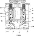
- a hand-held vacuum cleaner 2 comprising a main body 4, a handle 6 connected to the main body, a cyclonic separation apparatus 8 mounted transverse across the main body, and a dirty air duct 10 with a dirty air inlet 12 at one end.
- the vacuum cleaner comprises a motor coupled to a fan for generating air flow through the vacuum cleaner and rechargeable cells (not shown) to energise the motor when electrically coupled by an on / off switch 14.
- the motor has a drive shaft 20 with a central axis 21.
- the fan is a centrifugal fan 18 with an axial input 22 facing the motor and a tangential output 24.
- the fan has a diameter of 68 mm.
- the fan is mounted upon the drive shaft at the top of the motor.
- the motor drives the fan to generate air flow through the cyclonic separation apparatus, as will be described in more detail below.
- a small portion of the drive shaft 20 protrudes from the bottom of the motor 16.
- a second fan, comprising a paddle wheel 26, is mounted upon the drive shaft 20 at the bottom of the motor.
- the motor and the paddle wheel are clad in a cylindrical outer body of the motor, which is often referred to as a "motor can". In use, the motor turns the paddle wheel to circulate and augment air flow inside the motor can and about the bottom of the motor.
- the motor 16 and the fan 18 are housed in a motor fan housing 27 comprising a generally cylindrical body portion 28 enclosing the motor and a generally circular head portion 29 enclosing the fan.
- the head portion 29 has a larger diameter than the body portion 28.
- the motor fan housing 27 comprises a perforated end cap 30 mounted upon the head portion on the opposite side to the body portion.
- the end cap 30 protects the fan.
- the end cap has a circular array of perforations 36 near where air flow is expelled from the fan.
- the head portion acts as a baffle to direct air flow from the fan and out the perforations.
- the body portion has an array of bottom slots 32 around the bottom of the motor and an array of top slots 34 about where the drive shaft 20 protrudes from the top of the motor.
- the cyclonic separation apparatus 8 comprises a pre-fan filter 40, a vortex finder assembly 50, a generally cylindrical inner wall 60, a cyclone seal 70, a cyclone assembly 80, a cylindrical perforated intermediate wall 90, a circular bulkhead 100, a tapered funnel 110, a transparent generally cylindrical dirt container 120, and a circular bowl door 130 all arranged about the central axis 21 of the motor drive shaft 20.
- the pre-fan filter 40 is an annular shape surrounding the top air flow slots 34 of the body portion 28 of the motor fan housing 27.
- the pre-fan filter is enclosed in an annular shell 42 except where the pre-fan filter communicates with the vortex finder assembly 50 and with the top air flow slots 34 of the body portion 28. This permits air flow from the cyclonic separating apparatus, through the pre-fan filter and on to the fan.
- the vortex finder assembly 50 comprises planar ring 52 moulded with twelve hollow cylindrical vortex finders 54 protruding from one side of the planar ring. Holes 56 through the vortex finders penetrate the opposite side of the planar ring whereupon the pre-fan filter 40 is seated.
- the pre-fan filter 40 helps to muffle high frequency sounds caused by Helmholtz resonance as air flows through the vortex finder holes 56.
- the vortex finders are arranged in a circular array about the central axis 21 of the motor drive shaft 20. Each vortex finder has its own longitudinal central axis 57 arranged parallel to the central axis 21.
- the vortex finders may have longitudinal internal ribs (not shown) along the vortex finder holes to further reduce high frequency noise caused by Helmholtz resonance.
- the longitudinal ribs also tend to straighten air flow in the vortex finder to help reduce energy losses as the air flows into the pre-fan filter 40.
- the inner wall 60 is a generally cylindrical shape in two portions of different diameter.
- the inner wall comprises an annular flange 62 at an open end of the inner wall, a hollow cylindrical cup 64 at an opposite closed end of the inner wall, a hollow cylindrical wall 66 and an annular shoulder 68.
- the flange extends radially outwardly from the open end of the cylindrical wall.
- the cylindrical wall is located between the flange and the cylindrical cup.
- the cylindrical wall has a larger diameter than the cylindrical cup.
- the annular shoulder joins the cylindrical wall to the cylindrical cup.
- the shoulder is perforated with a circular array of twelve holes 69 spaced at equi-angular intervals about the central axis 21.
- the annular flange 62 is connected to an annular roof wall 121 of the dirt container 120.
- the vortex finder assembly 50 is seated in the cylindrical wall 66 with the planar ring 52 facing the shoulder 68 and the vortex finders 54 protruding through the shoulder's holes 68.
- the pre-fan filer 40 is nested within the cylindrical wall 66.
- the bottom of the motor fan housing's body portion 28 is nested within the cylindrical cup 64.
- the cyclone seal 70 is perforated with a circular array of twelve holes 72 spaced at equi-angular intervals about the central axis 21.
- the shoulder 68 of the inner wall 60 is seated upon the cyclone seal.
- the vortex finders 54 protrude through the seal holes 72.
- the cyclone assembly 80 comprises a cylindrical collar 82 and a circular array of twelve cyclones 84 surrounded by the collar.
- the cyclones are spaced at equi-angular intervals about the central axis 21.
- Each cyclone has a hollow cylindrical top part 85 and a hollow frustro-conical bottom part 86 depending from the cylindrical top part and terminating with a discharge nozzle 87 at the bottom of the cyclone.
- the shoulder 68 of the inner wall 60 is arranged upon the cyclone assembly 80 with the cyclone seal 70 interposed therebetween.
- the collar 82 has the same outer diameter as, and abuts with, the cylindrical wall 66 of the inner wall 60.
- the vortex finders 54 protrude through the holes 72 in the cyclone seal and into the cylindrical top part 85 of a respective cyclone 84.
- the only passage through the top of the cyclone 84 is via its vortex finder 54 which acts as an air flow outlet port to the pre-fan filter 40.
- Each vortex finder is concentric with its respective cyclone.
- the plane of each nozzle 87 is inclined with respect to the central axis 57. This helps to prevent dust and dirt particles from re-entry after discharge from the nozzle.
- each cyclone 84 has an air inlet port 88 arranged tangentially through the side of the cyclone and proximal the vortex finder 54.
- the twelve air inlet ports are in communication with a distribution chamber 170 below the collar 82 around the cyclones 84, as is described in more detail below.
- the intermediate wall 90 is arranged upon the cyclone assembly 80.
- the intermediate wall 90 has the same outer diameter as, and abuts with, the cylindrical collar 82.
- the bulkhead 100 is arranged upon, and has approximately the same outer diameter as, the intermediate wall 90.
- the bulkhead 100 is perforated by a circular array of twelve holes 102 spaced at equi-angular intervals about the central axis 21.
- the discharge nozzles 87 of the cyclones 84 protrude through respective bulkhead holes 102.
- the bulkhead 100 has a circumferential lip 104 inclined radially outwardly from the central axis 21 towards the bowl door 130. The lip 104 protrudes a small way from the intermediate wall 90.
- the tapered funnel 110 comprises a hollow circumferential skirt 112, a frustro-conical cone 114 depending from the skirt, and a hollow cylindrical nose 116 depending from the cone.
- the skirt is arranged upon, and has approximately the same outer diameter as, the bulkhead.
- the cone tapers radially inwardly from the bulkhead 100 towards the bowl door 130.
- a perforated portion 118 of the skirt protrudes axially rearward from the cone towards the bowl door 130.
- the generally cylindrical dirt container 120 comprises the annular roof wall 121 and a hollow cylindrical exterior wall 122 with a frustro-conical dirt collection bowl 124 depending from the exterior wall.
- the dirt container has a dirty air inlet port 126 arranged tangentially through the exterior wall 122.
- the dirt container 120 has a circumferential lip 128 inclined radially inwardly towards the central axis 21 and towards the bowl door 130. The lip 128 protrudes a small way in from the transition between the exterior wall and the dirt collection bowl.
- the motor fan housing's head portion 29 is nested within the centre of the annular roof wall 121.
- the annular roof wall is detachably connected to an outer circumferential edge 138 of the exterior wall 122.
- the annular roof wall 121 may be connected to the exterior wall 122 and the inner wall 60 by snap-fit, bayonet fit, interlocking detents, interference fit or by a hinge.
- a resilient seal or seals made of polyethylene, rubber or a similar elastomeric material is provided around the annular roof wall to ensure airtight connection with the exterior wall.
- the bowl door 130 is detachably connected to an outer circumferential edge 132 of the dirt collection bowl 124.
- the bowl door abuts the cylindrical nose 116 thereby dividing the dirt collection bowl into two separate chambers: a generally circular chamber 134 inside the tapered funnel 110 and a generally annular chamber 162 outside the tapered funnel.
- the bowl door 130 may be connected to the dirt collection bowl 124 by snap-fit, bayonet fit, interlocking detents, interference fit or by a hinge.
- a resilient seal made of polyethylene, rubber or a similar elastomeric material is provided around bowl door 130 to ensure airtight connection with the dirt collection bowl.
- the annular flange 62 of the inner wall 60 is in complementary mating relationship with a circular ring 123 protruding from inside the annular roof wall 121.
- the nose 116 is in complementary mating relationship with a circular ring 140 protruding from inside the bowl door 130. This ensures that components of the cyclonic separation apparatus 8 remain concentric with the central axis 21 when the bowl door is closed.
- the various components of the cyclonic separation apparatus 8 are arranged upon each other by detachable connection, typically a snap-fit, bayonet fit, interlocking detents, or interference fit.
- detachable connection typically a snap-fit, bayonet fit, interlocking detents, or interference fit. The permits disassembly and reassembly, without tools, of the cyclonic separation apparatus 8 in order to clean, or replace, its individual components.
- Resilient seals made of polyethylene, rubber or a similar elastomeric material, or other suitable seal material, are provided around connections of the annular flange 62 and pre-fan filter shell 42 with the annular roof wall 121.
- the seals are to ensure airtight connection.
- the internal diameter of the dirt container 120 and the bowl door 130 is large enough to permit removal of the components of the cyclonic separation apparatus 8 (i.e. pre-fan filter 40, vortex finder assembly 50, inner wall 60, cyclone seal 70, cyclone assembly 80, intermediate wall 90, bulkhead 100, tapered funnel 110) through either end of the dirt container.
- dirty air flows, under the influence of the fan 18, in the dirty air inlet 12, up the dirty air duct 10 and into the cyclonic separation apparatus 8 where dust and dirt entrained in the air flow is separated therefrom.
- the dust and dirt is collected within the cyclonic separation apparatus.
- the air flows out the cyclonic separation apparatus 8, through the pre-fan filter 40, into the motor fan housing 27 via the top slots 34, though the fan 18 and out the perforations 36 in the end cap 30.
- the cyclonic separation apparatus 8 is divided into a first cyclonic separating unit 160, a second cyclonic separating unit 150 and a distribution chamber 170.
- the first cyclonic separating unit is located in the air flow pathway upstream of the distribution chamber.
- the distribution chamber is located in the air flow pathway upstream of the second cyclonic separating unit.
- the first cyclonic separating unit 160 comprises the cylindrical dirt container 120.
- the second cyclonic separating unit 150 comprises the circular array of twelve cyclones 84.
- the dirt container is concentric with the central axis 21 of the motor drive shaft 20.
- the distribution chamber 170 is bounded by the hollow cylindrical cup 64 of the inner wall, cyclone assembly 80, intermediate wall 90 and bulkhead 100.
- the second cyclone unit 150 received air flow from the first cyclone unit 160 via the distribution chamber 170.
- the exterior wall 122 of the dirt container 120 has a diameter of approximately 130mm.
- the cyclones 84 have a much smaller diameter than the dirt container. Helical air flow in the cyclones experiences greater centrifugal forces than in the annular chamber. Thus, the cyclones of the second cyclonic separating unit 150, when combined, have higher separation efficiency than the dirt container of the first cyclonic separating unit 160.
- dirty air flows into the first cyclonic separating unit 160 via the dirty air inlet port 126.
- the tangential arrangement of the dirty air inlet port 126 causes the dirty air to flow in a helical path around the cylindrical dirt container 120. This creates an outer vortex in the dirt container. Centrifugal forces move the comparatively large dust and dirt particles outwards to strike the side of the dirt container and separate them from the air flow.
- the dust separated and dirt (D) swirls towards the dirt collection bowl 124 where it is deposited.
- partially-cleaned air flows back on itself to follow an inner helical path closely about the tapered funnel 110 and towards the cylindrical intermediate wall 90.
- the partially-cleaned air flows through the perforated portion 118 of the tapered funnel's skirt 112 largely unimpeded.
- the circumferential lip 104 of the bulkhead 100 and the lip 128 of the dirt container 120 converge at a width restriction X in the first cyclonic separating unit 160.
- the width restriction reduces a radial width between the dirt container and the intermediate wall by at least 15 percent
- the width restriction tapers towards the bowl door 130 so that air, and entrained dirt, can flow more easily towards the bowl door than in the opposite direction.
- the circumferential lips 104, 128 and perforated portion 118 of the tapered funnel's skirt 112 catch separated dirt in the bowl 124 before it can be re-entrained in the partially-cleaned air flow.
- the partially-cleaned air flows through perforations in the intermediate wall, which filters any remaining large dirt particles, and into the distribution chamber 170.
- the air inlet ports 88 of the twelve cyclones are moulded into the collar 82 of the cyclone assembly 80.
- the distribution chamber 170 is in communication with the air inlet ports 88 of the twelve cyclones 84.
- the partially-cleaned air flow (double-headed arrows) divides itself, in the distribution chamber, evenly between the twelve air inlet ports 88 from where it flows into the twelve cyclones 84 of the second cyclonic separating unit 150.
- the air inlet ports 88 direct the partially-cleaned air flow in a helical path around the vortex finders 54. This creates an outer vortex inside each cyclone 84.
- cleaned air flows back on itself to follow a narrow inner helical path through the middle of the cyclone 84.
- the cleaned air flows out the internal hole 56 of the vortex finder 54, under the influence of the fan, into the pre-fan filter 40.
- the pre-fan filter 40 is to remove any fine dust and dirt particles remaining in the air flow after the cyclonic separation apparatus 8.
- the pre-fan filter is in communication with the motor fan housing 27. Cleaned air flows, via the top slots 34 in the motor fan housing, to the axial input 22 of the fan 18, out the tangential output 24 of the fan and through the perforations 36 of the end cap 30 where it is exhausted from the vacuum cleaner 2. Dust and dirt separated by the first and second cyclonic separating units and deposited in the dirt collection bowl 124 which can be emptied by opening the bowl door 130.
- each vortex finder seal forms a webbed collar around three consecutive vortex finders 54.
- the vortex finder seals 58 seal the connection between the vortex finder assembly 50 and the inner wall 60 except where the gaps 59 are located.
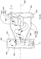
- FIG. 9F there is shown the pathway of clean motor cooling air (single-headed arrow) flow through the motor 16 and fan 18.
- the four motor cooling inlet ports are in communication with a first motor cooling passage 61 a between the shell 42 of the pre-fan filter 40 and the cylindrical wall 66 of the inner wall 60.
- FIG. 9G there is shown a longitudinal cross-section of a vortex finder 54 in the region of Detail X of Figure 9F .
- the vortex finder seal 58 blocks communication between the first motor cooling passage 61a and a second motor cooling passage 61b between the motor fan housing 27 and the cylindrical cup 64 of the inner wall 60.
- FIG. 9H there is shown a longitudinal cross-section between two vortex finders 54 and two vortex finder seals 58 in the region of Detail X of Figure 9F .
- the gap 59 between the vortex finder seals 58 permits communication between the first and second motor cooling passages 61 a, 61 b.
- the motor cooling inlet ports 31 are spaced at equiangular intervals about the central axis 21.
- the motor cooling inlet ports are axially aligned with the gaps 59 between the vortex spaces seals 58 and with the bottom air flow slots 32 in the motor fan housing 27. This axial alignment is to help minimise any resistance encountered by the motor cooling air flow along the motor cooling passages 61a, 61b.
- the bottom motor vents 17a are also aligned with the bottom air flow slots 32 in the motor fan housing 27 to help minimise any resistance encountered by the motor cooling air flow.
- the clean motor cooling air flow pathway is separate from the air flow pathway through the cyclonic separation apparatus 8 up to the axial input of the fan 18. This has particular benefits in vacuum cleaning. Typically, motor speed increases as the fan encounters resistance to volumetric air flow and the pressure across the fan increases accordingly. An example of how this may occur is when the vacuum cleaner is operational and the dirty air inlet contacts carpet, hard floor, curtains or other surface to restrict air flow. Should the air flow path through the cyclonic separation apparatus 8 become blocked, or impeded, for whatever reason, the motor cooling air flow path would not necessarily be blocked, or impeded. Instead, the increased pressure across the fan 18 would increase suction through the motor cooling air flow pathway. This has the benefit of increased motor cooling when the motor is working hardest and cooling is needed most.
- FIG. 44 there is shown a table of test data relating to the temperature of the motor 16. Two thermocouples were attached to the motor can while the motor was driving the fan 18 to generate air flow.
- the cyclonic separation apparatus 8 was subjected to three separate tests involving different operational conditions: (a) free air flow (dirty air inlet 12 fully open); (b) maximum power output (air watts) of cyclonic separation apparatus; and (c) sealed suction (dirty air inlet 12 closed).
- air watt is a measurement of vacuum power calculated from volumetric flow rate (volume / time) multiplied by suction (force / area) multiplied by a correction factor depending on humidity and atmospheric pressure.
- the ambient temperature was measured and compared to the motor temperature after ten minutes run time.
- the same three tests were carried out with four motor cooling inlet ports 31 and then repeated with one of the four motor cooling inlet ports 31 closed.
- the test data clearly reveal the benefits of the motor cooling air flow pathway and the importance of having four motor cooling inlet ports 31.
- a hand-held vacuum cleaner 202 comprising a main body 204 with a main axis 205, a handle 206, a cyclonic separation apparatus 208 mounted transverse to the main axis of the main body, and a dirty air duct 210 with a dirty air inlet 212 at one end.
- the vacuum cleaner comprises a motor 216 coupled to a fan for generating air flow through the vacuum cleaner and rechargeable cells 217 to energise the motor when electrically coupled by an on / off switch 214.
- FIG. 12 to 16 there is shown an arrangement comprising the motor 216, the rechargeable cells 217, the fan 218, a pre-fan filter 240, a cyclonic separation apparatus outlet duct 260 and the cyclonic separation apparatus 208.
- the motor has a drive shaft 220 with a longitudinal central axis 221.
- the fan is a centrifugal fan 218 with an axial input 222 facing away from the motor and a tangential output 224.
- the fan has a diameter of 68 mm.
- the fan is mounted upon the drive shaft at the top of the motor.
- the cells 217 are arranged in a circular array about the motor 216 with the longitudinal axis of the cells parallel to the central axis 221, as is shown most clearly in Figures 11 and 14 . In use, the motor drives the fan to generate air flow through the cyclonic separation apparatus, as will be described in more detail below.
- the main body 204 comprises a central housing 226, a motor housing 228, a frame 230 and an end cap 232.
- the fan 218 is housed in the central housing 226.
- the central housing is connected to the handle 206.
- the motor 216 and the cells 217 are housed in the motor housing 228.
- the motor housing is generally elongate to suit the profile of the cells.
- the end cap 230 is connected to an opposite end of the motor housing to the fan.
- the end cap has a circular array of perforations 236.
- the frame 230 connects the central housing 226 to the cyclonic separation apparatus 208.
- One end of the frame supports a pre-fan filter 240 arranged in front of the axial input 222 of the fan 218.
- the other end of the frame supports the cyclonic separation apparatus.
- the outlet duct 260 is defined by a generally oval-shaped duct wall 262 arranged upon the frame 230 to form the outlet duct between the duct wall and frame.
- the outlet duct 260 provides an air flow path between the cyclonic separation apparatus 208 and the pre-fan filter 240.
- the duct wall is detachable from the frame.
- the duct wall is transparent to permit visual inspection of the pre-fan filter. The duct wall is removed from the frame if the pre-fan filter needs cleaning or replacement.
- the cyclonic separation apparatus 208 comprises, a vortex finder assembly 250, a vortex finder seal 270, a cyclone assembly 280, a cylindrical perforated intermediate wall 290, a circular bulkhead 300, a tapered funnel 310, a transparent generally cylindrical dirt container 320 with a longitudinal central axis 321, and a circular dirt collection bowl 330 all arranged about the central axis 321 of the dirt container 320.
- the vortex finder assembly 250 comprises a planar generally circular base 252 with six hollow cylindrical vortex finders 254. Each vortex finder has a central through-hole 256 and its own longitudinal central axis 257. The vortex finders are arranged in a circular array about the central axis 321 of the dirt container 320. Each vortex finder is parallel to the central axis 321. The vortex finders protrude from one side of the base. A small portion of each vortex finder also protrudes from the opposite side of the base. The vortex finders may have longitudinal internal ribs (not shown) along the through-holes to help dampen high frequency sounds caused by Helmholtz resonance as air flows through the vortex finder though-holes 256.
- the cyclone assembly 280 comprises a generally cylindrical collar 282 and a circular array of six cyclones 284 surrounded by the collar.
- the cyclones are spaced at equi-angular intervals about the central axis 321 of the dirt container 320.
- Each cyclone has a hollow cylindrical top part 285 and a hollow frustro-conical bottom part 286 depending from the cylindrical top part and terminating with a discharge nozzle 287 at the bottom of the cyclone.
- the vortex finder assembly 250 is arranged upon the collar 282 of the cyclone assembly 280.
- the vortex finders 254 protrude into the cylindrical top part 285 of a respective cyclone 284.
- the only passage through of the top of the cyclone 284 is via its vortex finder 254 which acts as an air flow port to the outlet duct 260.
- Each vortex finder is concentric with its respective cyclone.
- the plane of each nozzle 287 is inclined with respect to the central axis 257. This helps to prevent dust and dirt particles from re-entry after discharge from the nozzle.
- each cyclone 284 has an air inlet port 288 arranged tangentially through a side of the cyclone and proximal the vortex finder 254.
- the six air inlet ports are in communication with a distribution chamber 370 located below the collar 282 around the cyclones 284 as described in more detail below.
- the intermediate wall 290 is arranged upon the cyclone assembly 280.
- the intermediate wall 290 has approximately the same outer diameter as, and abuts with, the cylindrical collar 282.
- the bulkhead 300 is arranged upon, and has approximately the same outer diameter as, the intermediate wall 290.
- the bulkhead 300 is perforated by a circular array of six holes 302 spaced at equi-angular intervals about the central axis 321.
- the discharge nozzles 287 of the cyclones 284 protrude through respective bulkhead holes 302.
- the bulkhead 300 has a circumferential lip 304 inclined radially outwardly from the central axis 321 towards the collection bowl 330.
- the lip 304 protrudes a small way from the intermediate wall 290.
- the tapered funnel 310 comprises a hollow circumferential skirt 312, a frustro-conical cone 314 depending from the skirt, and a hollow cylindrical nose 316 depending from the cone.
- the skirt is arranged upon, and has approximately the same outer diameter as, the bulkhead 300.
- the cone tapers radially inwardly from the bulkhead towards the collection bowl 330.
- a perforated portion 318 of the skirt protrudes axially rearward from the cone towards the collection bowl 330.
- the generally cylindrical dirt container 320 comprises a hollow cylindrical exterior wall 322 with a circular shoulder 324 extending radially inwardly from the top of the exterior wall.
- the dirty container has a dirty air inlet port 326 arranged tangentially through the exterior wall 322.
- the dirty air inlet port communicates with the dirty air duct 210.
- the exterior wall 322 is rotatingly connected to the frame 230 to enable the cyclonic separation apparatus 208 to rotate about its central axis 321 in relation to the main body 204.
- the dirty air duct 210 is rotatable with the cyclonic separation apparatus 208, as is shown in Figure 11 where the dirty air duct is in a folded position.
- the planar base 252 of the vortex finder assembly 250 nests within the aperture in the circular shoulder 324 of the dirt container 320.
- the collar 282 of the cyclone assembly 280 abuts the circular shoulder 324.
- the cyclones 284 are located within the dirt container 320.
- the dirt collection bowl 330 is detachably connected to an outer circumferential edge 332 of the dirt container 320.
- the dirt collection bowl abuts the nose 316 thereby dividing the dirt container and dirt collection bowl into two separate chambers: a circular chamber 334 inside the tapered funnel 310 and a generally annular chamber 362 outside the tapered funnel.
- the dirt collection bowl 330 may be connected to the dirt container's outer circumferential edge by snap-fit, bayonet fit, interlocking detents, interference fit or by a hinge.
- a resilient seal 336 made of polyethylene, rubber or a similar elastomeric material is provided around the dirt collection bowl 330 to ensure airtight connection with the dirt container.
- the dirt container 320 has an annular lip 328 inclined radially inwardly to the central axis 321 towards the collection bowl 330.
- the lip 328 protrudes a small way in from the exterior wall.
- the lip 328 is proximal to the bowl 330.
- the nose 316 of the tapered funnel 310 is in complementary mating relationship with a circular ring 340 protruding from inside the dirt collection bowl 330. This ensures that components of the cyclonic separation apparatus 208 remain concentric with the central axis 321 of the dirt container 320.
- dirty air flows, under the influence of the fan 218, in the dirty air inlet 212, up the dirty air duct 210 and into the cyclonic separation apparatus 208 where dust and dirt entrained in the air flow is separated therefrom.
- the dust and dirt is collected within the cyclonic separation apparatus.
- the air flows out the cyclonic separation apparatus 208, via the through-holes 256 of the vortex finders, along the outlet duct 260, through the pre-fan filter 240, through the fan 218 and over the motor 216 and batteries cells 217 via the motor housing 228 and out the perforations 236 in the end cap 230.
- the cyclonic separation apparatus 208 is divided into a first cyclonic separating unit 360, a second cyclonic separating unit 350 and the distribution chamber 370.
- the first cyclonic separating unit is located in the air flow pathway upstream of the distribution chamber.
- the distribution chamber is located in the air flow pathway upstream of the second cyclonic separating unit.
- the first cyclonic separating unit 360 comprises the cylindrical dirt container 310.
- the second cyclonic separating unit 350 comprises the circular array of six cyclones 284.
- the dirt container is concentric with the central axis 321 of the dirt container.
- the distribution chamber 370 is bounded by the collar 282, cyclone assembly 280, intermediate wall 290 and bulkhead 300.
- the second cyclonic separating unit 350 receives air flow from the first cyclonic separating unit 360 via the distribution chamber 370.
- the exterior wall 322 of the dirt container 320 has a diameter of approximately 120mm.
- the cyclones 284 have a smaller diameter than the annular chamber 362. Helical air flow in the cyclones experiences greater centrifugal forces than in the dirt container.
- the cyclones of the second cyclonic separating unit 350 when combined, have higher separation efficiency than the dirt container of the first cyclonic separating unit 360.
- dirty air flows from the dirty air duct 210 and into the dirt container 320 via the dirty air inlet port 326.
- the tangential arrangement of the dirty air inlet port 326 causes the dirty air to flow in a helical path around the dirt container. This creates an outer vortex in the dirt container. Centrifugal forces move the comparatively large dust and dirt (D) particles outwards to strike the side of the dust container 320 and separate them from the air flow. The separated dust and dirt swirls towards the dirt collection bowl 330 where it is deposited.
- partially-cleaned air flows back on itself to follow an inner helical path closely about the tapered funnel 310 and towards the cylindrical intermediate wall 290.
- the partially-cleaned air flows through the perforated portion 318 of the tapered funnel's skirt 312 largely unimpeded.
- the circumferential lip 304 of the bulkhead 300 and the lip 328 of the dirt container 320 converge at a width restriction Y in the first cyclonic separating unit 360.
- the width restriction reduces a radial width between the dirt container and the intermediate wall by at least 15 percent.
- the width restriction tapers towards the bowl 330 so that air, and entrained dirt, can flow more easily towards the bowl door than in the opposite direction.
- the circumferential lips 304, 328 and perforated portion 318 of the tapered funnel's skirt 312 catch separated dirt in the bowl 324 before it can be re-entrained in the partially-cleaned air flow.
- the partially-cleaned air flows through perforations in the intermediate wall, which filters any remaining large dirt particles, and into the distribution chamber 370.
- the air inlet ports 288 of the six cyclones are moulded into the collar 282 of the cyclone assembly 280.
- the distribution chamber 370 is in communication with the air inlet ports 288 of the six cyclones 284.
- the partially-cleaned air flow (double-headed arrows) divides itself, in the distribution chamber, evenly between the six air inlet ports 288 from where it flows into the six cyclones 284 of the second cyclonic separating unit 350.
- the air inlet ports 288 direct the partially-cleaned air flow in a helical path around the vortex finders 254. This creates an outer vortex inside each cyclone 284.
- Centrifugal forces move the dust and dirt outwards to strike the side of the cyclone and separate it from the air flow.
- the separated dust and dirt swirls towards the discharge nozzle 287.
- the internal diameter of the frustro-conical body 286 of cyclone diminishes as the air flow approaches the nozzle. This accelerates the helical air flow thereby increasing centrifugal forces and separating ever smaller dust and dirt particles.
- the dust and dirt particles exit the nozzle to be deposited inside the part of the bowl 330 bounded by the tapered funnel 310.
- cleaned air flows back on itself to follow a narrow inner helical path through the middle of the cyclone 284.
- the cleaned air flows out the internal through-hole 256 of the vortex finder 254, under the influence of the fan.
- the cleaned air flows from the vortex finders 254 into the outlet duct 260 and to the pre-fan filter 240.
- the pre-fan filter 240 is to remove any fine dust and dirt particles remaining in the air flow after the cyclonic separation apparatus 208 and before the fan 218.
- the clean air flows into the axial input 222 of the fan 218 and is expelled from the tangential output 224 of the fan.
- Pathways in the central housing 226 direct the clean air flow from the fan over the motor 216 and cells 217, to cool the motor and cells, before the air flows out the perforations 236 in the end cap 232.
- Dust and dirt separated by the first and second cyclonic separating units and deposited in the dirt collection bowl 330 which can be opened for emptying.
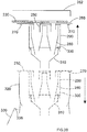
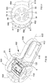
- FIG. 18 there is shown a diagrammatical view of the various components of the cyclonic separation apparatus 208 (vortex finder assembly 250, vortex finder seal 270, cyclone assembly 280, intermediate wall 290, bulkhead 300, tapered funnel 310) located within confines of the outlet duct 260, frame 230, dirt container 320 and dirt collection bowl 330.
- the vortex finder seal 270 seals the connections between the vortex finder assembly 250 and the dirt container 320 in an airtight manner.
- An outlet duct seal 266 seals the connection between the frame 230 and the outlet duct wall 262 in an airtight manner.
- the vortex finder seal 270 and the outlet duct seal 266 are made of polyethylene, rubber or a similar elastomeric material.
- Certain components of the cyclonic separation apparatus 208 are detachably connected, typically by a snap-fit, bayonet fit, interference fit or by interlocking detents. This permits disassembly and reassembly, without tools, of the cyclonic separation apparatus in order to clean, or replace, its individual components, as is described with reference to Figures 19 to 22 .
- FIG. 19 there is shown a method of disassembling a first construction of the cyclonic separation apparatus 208 whereby the outlet duct wall 262 is detachable from the frame 230.
- the dirt container 320 is detachable from the frame.
- the vortex finder assembly is detachable from the frame with, or without, the dirt container.
- the cyclone assembly 280, intermediate wall 290, bulkhead 300, and tapered funnel 310 are also detachable, in unison, from the vortex finder assembly.
- the dirt collection bowl 330 has a large enough diameter to enable, when the dirt collection bowl is opened, removal of the cyclone assembly 280, intermediate wall 290, bulkhead 300, and tapered funnel 310 out the dirt container 320.
- FIG. 20 there is shown a method of disassembling an alternative construction of the cyclonic separation apparatus 208 whereby the outlet duct wall 262 is detachable from the frame 230.
- the dirt container 320 is detachable from the frame.
- the vortex finder assembly 250, cyclone assembly 280, intermediate wall 290, bulkhead 300, and tapered funnel 310 are detachable, in unison, from the frame with, or without, the dirt container.
- the dirt collection bowl 330 is can be opened for emptying.
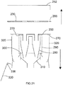
- FIG. 21 there is shown a method of disassembling a second alternative construction of the cyclonic separation apparatus 208 whereby the outlet duct wall 262 is detachable from the frame 230.
- the dirt container 320, vortex finder assembly 250, cyclone assembly 280, intermediate wall 290, bulkhead 300, and tapered funnel 310 are detachable, in unison, from the frame.
- the dirt collection bowl 330 can be opened for emptying.
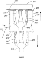
- FIG. 22 there is shown a method of disassembling a third alternative construction of the cyclonic separation apparatus 208 whereby the outlet duct 260 (i.e. duct wall 262 and frame 230) is detachable from the frame.
- the dirt container 320 remains with the frame.
- the vortex finder assembly 250, cyclone assembly 280, intermediate wall 290, bulkhead 300, and tapered funnel 310 are removable, in unison, from the frame when the dirt bowl 330 is opened.
- FIG. 23 there is shown a third embodiment of hand-held vacuum cleaner 402 comprising a main body 404 with a handle 406, a cyclonic separation apparatus 408 mounted to the main body, and a dirty air duct 410 with a dirty air inlet 412 at one end.
- the vacuum cleaner comprises a motor coupled to a fan for generating air flow through the vacuum cleaner and rechargeable cells to energise the motor when electrically coupled by an on / off switch 414.
- the motor has a drive shaft 420.
- the fan 418 is mounted upon the drive shaft at the top of the motor.
- the fan has a diameter of approximately 68 mm.
- the cells 417 are arranged about the motor 416. In use, the motor drives the fan to generate air flow through the cyclonic separation apparatus, as will be described in more detail below.
- the main body 404 comprises a central housing 426 and a frame 430.
- the motor 416, fan 418 and cells 417 are housed in the central housing 426.
- the central housing is connected to the handle 406.
- the central housing has an array of perforations 436 near the bottom of the motor. The perforations 436 are for air flow expelled from the central housing.
- the frame 430 connects the central housing 426 to the cyclonic separation apparatus 408.
- One end of the frame supports a pre-fan filter 440 arranged in front of the fan's input.
- the other end of the frame supports the cyclonic separation apparatus.
- the cyclonic separation apparatus is rotatingly connected to the frame.
- Outlet duct 460 comprises a duct wall 462 arranged upon the frame to form a passage between the duct wall and frame approximately 10mm deep.
- the outlet duct 460 provides an air flow path between the cyclonic separation apparatus 408 and the pre-fan filter 440.
- the duct wall is detachable from the frame.
- the duct wall is transparent to permit visual inspection of the pre-fan filter.
- a resilient seal made of polyethylene, rubber or similar elastomeric material is provided around the duct wall to ensure air tight connection with the frame. The duct wall is removed from the frame if the pre-fan filter needs cleaning or replacement.
- the cyclonic separation apparatus 408 comprises a vortex finder assembly 450, a cyclone assembly 480, and an elongate generally oval-shaped dirt container 520 with a transparent door 530.
- the vortex finder assembly 450 has a hollow cylindrical vortex finder 452 with a tapered deflector fin 454.
- the vortex finder has a central through-hole 456 with a longitudinal central axis 457.
- the deflector fin protrudes radially from the outer surface of the vortex finder.
- the tapered deflector fin is triangular although it could have another tapered profile.
- the triangular profile of the deflector fin 454 is a right angled triangle.
- the cyclone assembly 480 comprises a cyclone 484 and a dirty air inlet port 488.
- the cyclone has a hollow cylindrical body 485 with the dirty air inlet port and a hollow frustro-conical bottom body 486 extending from the cylindrical body and terminating with a discharge nozzle 487 at the narrower end.
- the air inlet port is arranged tangentially through a side of the cylindrical body.
- the vortex finder 454 is arranged inside the cyclone 484.
- the vortex finder is concentric with the cyclone.
- the deflector fin 454 is arranged transverse to the path of air flow from the air inlet port. The radially extending short side of the deflector fin abuts the frame 430.
- An apex 4541 of the deflector fin is proximal to the air inlet port.
- the hypotenuse side of the deflector fin tapers radially inwardly from the apex to the end of the vortex finder proximal to the discharge nozzle 487.
- the dirt container 520 is connected to the central housing 426 at one end and the discharge nozzle 487 of the cyclone 484 at the other end.
- the dirt container comprises a perimeter wall 522 following the outer perimeter of the elongate generally oval-shaped dirt container and base wall 524 with a cylindrical pocket 526 protruding from the base wall into the confines of the dirt container.
- the cyclone 484 is in communication with the dirt container where the nozzle 487 protrudes through the base wall 524.
- the bottom of the motor 416 is seated inside the pocket 526 on the opposite side to the dirt container thereby reducing the overall width of the vacuum cleaner by about 20 to 25 mm.
- the cyclone 484 has a curved fin 490 protruding axially from the discharge nozzle 487 into the dirt container 520.
- the curved fin circumscribes an arc of about half the circumference of the nozzle facing the pocket 526. The ends of the curved fin taper towards the nozzle.
- the dirt container has a flat fin 492 protruding from the base wall 524.
- the flat fin extends tangentially from the top of the pocket 526 to about the middle of the dirt container.
- the flat fin is generally parallel to an adjacent initial flat portion 522a of the perimeter wall 522 uppermost on the dirt container in normal use.
- the door 530 is detachably connected to the perimeter wall 522 of the container 520.
- the door 530 may be connected to the dirt container by snap-fit, interlocking detents, a hinge 528 or by interference fit with the dirt container's exterior wall.
- the door is held firmly closed by a spring-loaded latch 529.
- a resilient seal (not shown) made of polyethylene, rubber or a similar elastomeric material is provided around the door 530 to ensure connection to the dirt container 320 in an airtight manner. Dust and dirt separated by the cyclonic separation apparatus and deposited in the dirt container 520 can be emptied by opening the door 530.
- the door is transparent to enable visual inspection of when the dirt container 520 is full and is in need of emptying.
- dirty air flows, under the influence of the fan 418, in the dirty air inlet 412, up the dirty air inlet duct 410 and into the cyclonic separation apparatus 408 where dust and dirt entrained in the air flow is separated therefrom.
- the dust and dirt is collected within the cyclonic separation apparatus.
- the partially-cleaned air flow (double-headed arrows) is directed by the curved fin 490 and a proximal curved portion 522d of the perimeter wall 522 to leave the cyclone 484 in an anti-clockwise upward direction, as viewed in Figure 24 .
- the flat fin 492 and the pocket 526 help to direct the partially cleaned air flow to follow an elongate circuit about the perimeter wall 522 of dirt container 520, similar in shape to a two-pulley belt drive wherein the discharge nozzle 487 simulates a pulley at one end and the pocket 526 simulates a pulley at the opposite end.
- the elongate circuit of air flow begins outbound away from the discharge nozzle in proximity to the initial flat portion 522b of the perimeter wall 522 and is redirected inside a distal curved portion 522c of the perimeter wall 522 to turn around the pocket 526 and continue inbound towards the discharge nozzle adjacent to a further flat portion 522d of the perimeter wall lower most on the dirt container in normal use.
- An axis of elongation of the elongate circuit runs approximately through the centres of the discharge nozzle and the pocket.
- the flat fin and the pocket prevent the bulk of the dust and dirt particles (D) from dropping out of the circulating air flow before being deposited upon the further flat portion 522d of the perimeter wall at the bottom of the dirt container.
- the perimeter wall 522 has a generally lozenge shape in cross-section parallel to the base wall 524.
- the initial flat portion 522a and the further flat portion 522c of the perimeter wall taper inwardly and away from the distal curved portion 522b of the perimeter wall. This encourages deposit of dust and dirt around the pocket end of the dirt container where there is more space than at the opposite discharge nozzle end of the dirt container.
- the curved fin 490 acts as an obstacle to laminar air flow inbound to the discharge nozzle. The air flow is forced to deviate around the curved fin. This disruption of laminar air flow provokes deposit of any remaining entrained dirt and dust (D) in the dirt container.
- the shape of the perimeter wall 522, the flat fin 492, the pocket 526 and the curved fin 490 combine to help to separate any remaining dust and dirt from air flow path destined for the pre-fan filter 440. This increases sustained performance of the vacuum cleaner 502.
- FIG. 29 to 38 there is shown a variety of battery-powered vacuum cleaners with the motor 16, fan 18 and cyclonic separation apparatus 8 arrangement of the first embodiment.
- the arrangement is, in all examples, arranged with the central axis 21 of the drive shaft 20 orientated transverse a main axis of the main body of the vacuum cleaner.
- a hand-holdable vacuum cleaner 602 with pivotable dirty air duct 610 a hand-holdable vacuum cleaner 702 connected to a cleaning nozzle 712 by a flexible hose 710 to resemble a small cylinder vacuum cleaner; and a vacuum cleaner 802 with an elongate body 806, a support wheel 807 and a cleaner head 812 to resemble an upright vacuum cleaner, also commonly referred to as a "stick-vac”.
- the hand-holdable vacuum cleaner 602 comprises a main body 604 with a main axis 605 and a handle 606.
- the motor 16, fan 18 and cyclonic separation apparatus 8 of the first embodiment are rotatingly connected to the main body 604 at the annular roof wall 121 of the dirt container 120.
- the central axis 21 of the cyclonic separation apparatus is orientated at a right angle (i.e. transverse) to the main axis of the main body.
- the vacuum cleaner 602 comprises a battery pack 900 of rechargeable cells 917 to energise the motor 16 when electrically coupled by an on / off switch.
- the dirty air duct 610 is connected to the air inlet port 126.
- the battery pack 900 has a curvilinear cross-sectional profile with a curvilinear inner wall 902 shaped to fit around the cylindrical dirt container 120.
- the battery pack 900 has a pair of electrical contacts 904 on a curvilinear outer wall 906 so that the cells may be recharged in situ.
- the battery pack is detachably connected to the dust container 120.
- the battery pack may be detached from the duct container to enable replacement, or external recharging of the cells, if necessary.
- the cells have a generally cylindrical shape. Longitudinal axes of cells are arranged parallel to the central axis 21 of the motor 16.
- the dirty air duct 610 and the battery pack 900 are rotatable, with the cyclonic separation apparatus 8, about the central axis 21 through an arc subtending 210 degrees from a folded position.
- This allows the vacuum cleaner 602 to be pointed in different directions, whilst a user is able to hold the vacuum cleaner in the same orientation.
- the vacuum cleaner may be used to access awkward spaces and can be held more comfortably by orientating the main axis 605 of the main body 604 to suit the user and adjusting the position of the dirty air inlet 612 to point at a surface to be cleaned, rather than orientating the main axis to best suit the surface to be cleaned and requiring the user to hold the vacuum cleaner in whichever orientation this demands.
- Figures 29 and 30 show the vacuum cleaner 602 in the folded position where the dirty air duct is folded at zero degrees under the handle 606 for compact storage.
- the battery pack 900 is rotated to the diametrically opposite side of the dirt container 120.
- the vacuum cleaner may be cradled by a battery charger 916 in the upright position shown in Figure 29 . This allows the vacuum cleaner to be stood in a small surface area and without excessive height because the dirty air duct is folded under the handle. Arranged like this, the vacuum cleaner is easier to grab.
- the vacuum cleaner's centre of gravity is lowered by the battery pack thus making the upright position more stable.
- the cells 917 are electrically coupled by the electrical contacts 904 to the battery charger 916 for recharging in the upright position.
- Figure 32 shows the vacuum cleaner 602 in an extended position.
- the dirty air duct 610 is rotated through 180 degrees from the folded position and is ready for use.
- the dirty air duct 610 has been telescopically extended to double its length.
- the battery pack 900 occupies a gap 616 between the handle 606 and the dirt container 120.
- the battery pack is relatively heavy and its location in the gap 616 moves the vacuum cleaner's centre of gravity closer to the handle. This improves the ergonomics of the vacuum cleaner.
- the hand-holdable vacuum cleaner 702 comprises a body 704 with a handle 706.
- the motor 16, fan 18 and cyclonic separation apparatus 8 is connected to the body 704 at the annular roof wall 121 of the dirt container 120.
- the vacuum cleaner 702 comprises a pack 910 of rechargeable cells. The cells are to energise the motor 16 when electrically coupled by an on / off switch.
- the air inlet port 126 is connected to one end of the flexible hose 710.
- the cleaning nozzle 712 is connected to the other end of the flexible hose.
- the battery pack 910 has a curvilinear inner wall 902 which is shaped to cradle the cylindrical dust container 120.
- the battery pack is detachably connected to the dust container 120.
- the cells may be recharged in situ.
- the battery pack may be detached from the dirt container to enable replacement, or external recharging of the cells, if necessary.
- the battery pack has a pair of feet 912 arranged to support the vacuum cleaner 702 in a stable manner when placed upon a flat surface.
- the cells have a generally cylindrical shape. Longitudinal axes of the cells are arranged parallel to the central axis 21 of the motor 16.
- Figures 32 and 34 show a compact configuration of the vacuum cleaner 702.
- the flexible hose 710 is wrapped around the dirt container 120 and under the battery pack 910 via rebates 914 in the battery pack feet 912.
- the cleaning nozzle 712 is cradled by the handle 706.
- the handle is moulded in plastics material with natural resilience.
- the cleaning nozzle is gripped by the handle. The cleaning nozzle can be readily detached from the handle for use in vacuum cleaning.
- the vacuum cleaner 802 comprises the elongate body 804.
- the elongate body is telescopic.
- the elongate body has a handle 806 at one end and a bracket 805 at the other end.
- the motor 16, fan 18 and cyclonic separation apparatus 8 of the first embodiment are rotatingly connected to the bracket 805 at the annular roof wall 121 of the dirt container 120.
- the bracket arches around one side of the dirt container so that the latter may be connected transverse to the elongate body.
- the support wheel 807 surrounds the dirt container 120.
- the support wheel is supported for rotation about the dirt container by a bearing 809.
- the air inlet port 126 is connected to one end of the dirty air duct 810.
- the cleaner head 812 is connected to the other end of the dirty air duct 810.
- the cleaner head is pivotable in relation to the dirt container about a longitudinal axis 8100 of the dirty air duct.
- the dirty air duct is arranged tangentially to the dirt container.
- the vacuum cleaner comprises a battery pack 900 of rechargeable cells 917 to energise the motor 16 when electrically coupled by an on / off switch.
- the battery pack 900 has a curvilinear inner wall 902 which is shaped to embrace the support wheel 807 and part of the cylindrical dirt container 120.
- the battery pack is detachably connected to the bracket 805.
- the cells 917 may be recharged in situ.
- the battery pack may be detached from the bracket to enable replacement, or external recharging of the cells, if necessary.
- the cells have a generally cylindrical shape. Longitudinal axes of the cells are arranged parallel to the central axis 21 of the motor 16.
- FIG. 35 there is shown the vacuum cleaner 802, prepared for use, with the support wheel 807 and the cleaning head 812 upon a floor and the elongate body 804 fully extended.
- the support wheel 807 is arranged about the midpoint of the axial length of the dirt container.
- the diameter of support wheel 807 is approximately the same as the axial length of the dirt container 120 so that the elongate body can be rocked from side to side by about 45 degrees each way and the vacuum cleaner 802 can be steered with ease.
- the vacuum cleaner with the elongate body 804 fully retracted to approximately a quarter of the elongate body's extended length.
- the vacuum cleaner's overall length when the elongate body is extended is at least double the vacuum cleaner's overall length when the elongate body is retracted.
- the vacuum cleaner 802 is prepared for storage in a kitchen cupboard when the elongate body is retracted.
- the elongate body may be locked in its retracted and extended positions.
- any suitable locking system will suffice, like, for example, a spring-loaded detent interlockable with holes along the elongate body corresponding to the retracted position, the extended position and any intermediate position therebetween.
- FIG 38 there is shown in perspective the shape of the battery pack 900 and, in particular, the curvilinear inner wall 902 which is to embrace, or connect to, the outside of the dirt container 120 of the cyclonic separation apparatus 8.
- FIG. 39 there is shown the battery pack 900 along cross-section XXXVIII-XXXVIII.
- Commercially available rechargeable cells may be cylindrical in shape.
- Figure 39 shows five cylindrical cells 917 stacked in a curved array to conform to the internal cavity of the curvilinear cross-section profile of the battery pack.
- plate rechargeable cells 927 composed of flexible anode and cathode plates, or sheets, interposed by a polymer electrolyte material and separator material. The anode sheets are electrically connected to the positive cell terminal and the cathode sheets are electrically connected to the negative cell terminal, and those sheets can be connected in series or in parallel to form a battery pack.
- These plate cells are flexible and they can be stacked upon each other.
- Figure 40 shows three plate cells 927 stacked upon each other and curved to conform to the internal cavity of the curvilinear cross-section profile of the battery pack.
- annular battery pack 920 in cross-section which is adapted to surround the dirt container 120 of the cyclonic separation apparatus 8 with a hollow cylindrical inner surface 922.
- the annular battery pack has a cylindrical inner wall 922 and a cylindrical outer wall 926.
- Figure 41 shows 12 cylindrical cells 917 arranged in a circular array to conform to the internal cavity of the annular cross-sectional profile of the annular battery pack 920.
- Figure 42 shows three plate cells 927 stacked upon each other and curved into a hollow cylindrical shape to conform to the internal cavity of the annual cross-section of the annular battery pack 920.
- Figure 43 shows five plate cells 927 wound into a hollow cylindrical shape to conform to the internal cavity of the annular cross-section of the annular battery pack 920.
- the curved plate cells 927 improve use of the internal cavity of the battery packs 920 by eliminating the gaps which naturally exist between the cylindrical cells 917. This results in a more compact design of battery pack with reduced packaging and a higher energy density.
- curvilinear or cylindrical inner walls 902,922 of the curvilinear battery pack 900,910 and the annular battery pack 920 embrace, or attach themselves to, the dirt container 120. This facilitates new design choices for accommodating cells in a compact manner.
- the rechargeable cells can be any type of energy accumulator, including rechargeable Lithium Ion, Nickel Metal Hydride or Nickel Cadmium rechargeable cells, for driving the electric motor 16, 216, 416.
- the specific overall shapes and sizes of the arrangements comprising the motor 16, 216, 416 the fan 18, 218, 418 and the cyclonic separation apparatus 8, 208, 408 can be varied according to the type of vacuum cleaner in which either of the arrangements is to be used.
- the overall length or width of each arrangement, and, in particular, the cyclonic separation apparatus can be increased or decreased with respect to its diameter, and vice versa.
- the hand-holdable vacuum cleaner 702 of Figures 33 and 34 can be modified to comprise the motor 216, fan 218 and cyclonic separation apparatus 208 of the embodiment by modifying the form of the battery pack 910 to suit the underside of the dirt container 320.
- the flexible hose 710 would need extension to be wrapped around the dirt container 320 and the central housing 226 and motor housing 228.
- the hand-holdable vacuum cleaner 802 of Figures 35 to 38 can be modified to comprise the motor 216, fan 218 and cyclonic separation apparatus 208 of the second embodiment by substituting the central housing 226 and motor housing 228 for the main bracket 805. This could be done by attaching the elongate body 804 directly to the central housing 226 in place of the handle 206 and the bracket 805.
- the cyclonic separation apparatus outlet duct 260 would need extension to create enough clearance for the support wheel 807 and bearing 809 to surround the dirt container 320.
- the motor 16, 216, 416 discussed above is a typically a brushed d.c. motor with its drive shaft 20,220,420 directly coupled to the centrifugal fan 18, 218, 418.
- the motor's drive shaft has a rotational speed within a range of 25,000 and 40,000 revolutions per minute (rpm).
- a centrifugal fan with a rotational speed within this range has an outer diameter approximately double the outer diameter of the motor can in order to have sufficient tip speed to generate the required volumetric flow rate through the cyclonic separation apparatus.
- the motor 16,216,416 can be a d.c. motor, an a.c. motor, or an asynchronous multi-phase motor controlled by an electronic circuit.
- a permanent magnet brushless motor, a switched reluctance motor, a flux switching motor, or other brushless motor type may have a high rotational speed within a range of 80,000 to 120,000 rpm. If such a high speed motor were used then the fan diameter could be at least halved and yet still generate the required volumetric flow through the cyclonic separation apparatus because the fan's tip speed would be so much higher. This would make the fan's outer diameter the same as the motor can's outer diameter and could possibly make it less than the motor can's outer diameter if the motor operates at around the upper end of the high rotational speed range.
- a smaller diameter fan operating within this range of high rotational speeds would typically be an impeller although it may be an axial fan or a centrifugal fan.
- the outer profile of the smaller fan coupled to the drive shaft of the high rotational speed motor would have a generally cylindrical outer profile. This provides additional flexibility in the layout of the cyclonic separation apparatus.
- the cyclones 84,284 can be rearranged to accommodate a high rotational speed permanent magnet brushless motor, a switched reluctance motor or a flux switching motor coupled to a fan which is coaxial with the motor and has an outer diameter substantially the same as or less than the outer diameter of the motor.
- the generally cylindrical outer profile of high speed motor and fan can be sunk into the cyclonic separation apparatus amongst the cyclones and clustered into a generally circular array. Air flow can be directed to the axial input of the fan and expelled from the tangential output of the fan by a baffle.
- the high speed motor and fan may be located on the periphery of the circular array in which case air flow from the fan may be expelled from one side of the circular array and directed out of the cyclonic separating apparatus.
- the high speed motor and fan may be nested near, or at, the middle of the circular array in which case air flow from the fan may be expelled from one end of the circular array and directed out of the cyclonic separating apparatus.
- air flow from the fan may be expelled from one end of the circular array of cyclones or through gaps between the cyclones.
Abstract
Description
- The present invention relates to a cyclonic separation apparatus. In particular, but not exclusively, the present invention relates to a cyclonic separation apparatus for use in vacuum cleaners.
- Vacuum cleaners are well known for collecting dust and dirt, although wet-and-dry variants which can also collect liquids are known as well. Typically, vacuum cleaners are intended for use in a domestic environment, although they also find uses in other environments, such as worksites or in the garden. Generally, they are electrically powered and therefore comprise an electric motor and a fan connected to an output shaft of the motor, an inlet for dirty air, an outlet for clean air and a collection chamber for dust, dirt and possibly also liquids. Electrical power for the motor may be provided by a source of mains electricity, in which case the vacuum cleaner will further comprise an electrical power cable, by a removable and replaceable battery pack, or by one or more in-built rechargeable cells, in which case the vacuum cleaner will further comprise some means, such as a jack plug or electrical contacts, for connecting the vacuum cleaner to a recharging unit. When the vacuum cleaner is provided with electrical power from one of these sources, the electric motor drives the fan to draw dirty air along an air flow pathway in through the dirty air inlet, via the collection chamber to the clean air outlet. The fan is often a centrifugal fan, although it can be an impeller or a propeller.
- Interposed at some point along the air flow pathway, there is also provided some means for separating out dust and dirt (and possibly also liquids) entrained with the dirty air and depositing these in the collection chamber. This dirt separation means may comprise a bag filter, one or more filters and/or a cyclonic separation apparatus.
- In the event that the dirt separation means comprises a bag filter, dirty air, which has entered the vacuum cleaner via the dirty air inlet, passes through the bag filter. This filters out, and collects within the bag filter, dust and dirt entrained with the dirty air. The filtered material remains in the bag filter which lines the collection chamber. The clean air then passes to the other side of bag filter and through a grille in the collection chamber under the influence of the fan. The fan draws air in and expels it out, from where the air then passes to the clean air outlet of the vacuum cleaner.
- There is always a small risk of dust and dirt passing through the bag filter and it is undesirable that it be allowed to pass through the fan and cause damage. To reduce this potential problem, there is often a fine filter located across the grille of the collection chamber to remove any fine dust and dirt particles remaining in the air flow after passage through the bag filter. This is commonly known as a pre-fan filter.
- Occasionally, and in addition to any pre-fan filter, there is a high efficiency filter located downstream of the fan before the air flow leaves the vacuum cleaner. This is to remove any remaining extremely fine particulate matter which will not harm the fan or motor, but which may be harmful to the household environment. The term "filtering efficiency" is intended to relate to the relative size of particulate matter removed by a filter. For example, a high efficiency filter is able to remove smaller particulate matter from air flow than a low efficiency filter. A HEPA filter is a high efficiency filter which should be able to remove extremely fine particulate matter having a diameter of 0.3 micrometers (µm) and lower.
- The purpose of the bag filter is to filter dust and dirt entrained in dirty air flow and to collect the filtered material within the bag filter. This progressively clogs the bag filter. The volumetric flow rate of air through the vacuum cleaner is progressively reduced and its ability to pick up dust and dirt diminishes correspondingly. Hence, the bag filter needs replacement before it becomes too full and before vacuum cleaner performance becomes unacceptable. The volume of the collection chamber must be sufficiently large to merit the cost of regular bag filter replacement.
- An upright vacuum cleaner commonly has an upright main body with a dirt separating means, a motor and fan unit, a handle at the top and a pair of support wheels at the bottom. A cleaner head with a dirty air inlet facing the floor is pivotally mounted to the main body. A cylinder vacuum cleaner commonly has a cylindrical main body with a separating dirt means, a motor and fan unit and maneuverable support wheels underneath. A flexible hose with a cleaner head communicates with the main body. Bag filters are commonly used in upright and cylinder vacuum cleaners as separation means because their main body has sufficient internal space for the large collection chamber required to accommodate the bag filter.
- In the event that the dirt separation means comprises a filter, dirty air, which has entered the vacuum cleaner via the dirty air inlet, passes through the filter. This filters out dust and dirt entrained with the dirty air and the filtered material remains in the collection chamber on the upstream side of the filter. Sometimes the filter is supplemented by a sponge to absorb any liquids entrained in the dirty air flow. The clean air then passes to the other side of filter under the influence of the fan, and from the fan the air then passes to the clean air outlet of the vacuum cleaner.
- Filtered material accumulates around, and progressively clogs, the filter. The volumetric flow rate of air through the vacuum cleaner is progressively reduced and its ability to pick up dust and dirt diminishes correspondingly. Hence, the collection chamber needs regular emptying and the filter needs frequent cleaning to mitigate against this effect. Sometimes, the vacuum cleaner has a filter cleaning mechanism. Alternatively, the filter needs to be removable for cleaning with a brush, or in a dish washer, for example.
- Hand-holdable vacuum cleaners, as their name would suggest, are compact and lightweight and are intended to perform light, or quick, cleaning duties around a household. Typically, hand-holdable vacuum cleaners are battery-powered to be easily portable.
- An example of a hand-holdable vacuum cleaner having the conventional motor, fan and filter arrangement is described in European patent publication no.
EP 1 752 076 A , also in the name of the present applicant. This vacuum cleaner has dirty air inlet at one end of a dirty air duct leading to a collection chamber with a filter. The collection chamber is generally cylindrical and is arranged transverse the body of the vacuum cleaner. The dirty air duct is rotatable, with the collection chamber, in relation to the body. The dirty air duct may be adjusted to access awkward spaces while the vacuum cleaner is held comfortably by a user. - In the event that the dirt separation means comprises cyclonic separation apparatus, dirty air, which has entered the vacuum cleaner via the dirty air inlet, passes through the cyclonic separation apparatus having one or more cyclones. A cyclone is a hollow cylindrical chamber, conical chamber, frustro-conical chamber or combination of two or more such types of chamber. The cyclone may have a vortex finder part way, or all way, along its internal length. The vortex finder is commonly a hollow cylinder and it has a smaller external diameter than the internal diameter of the cyclone.
- Dirty air enters via a tangentially arranged air inlet port and swirls around the cyclone in an outer vortex. Centrifugal forces move the dust and dirt outwards to strike the side of the cyclone unit and separate it from the air flow. The dust and dirt is deposited at the bottom of the cyclone and into a collection chamber below. An inner vortex of cleaned air then rises back up the cyclone. The role of a vortex finder is to gather and direct the cleaned air through an air outlet port at the top of the cyclone. As an alternative to a vortex finder, the cyclone may have an inner cylindrical air permeable wall providing the cleaned air with a path from the cyclone. From the cyclone the cleaned air passes, under the influence of the fan, to the clean air outlet of the vacuum cleaner.
- As with a bag filter, a vacuum cleaner with a cyclonic separation apparatus may have a pre-fan filter to protect the fan and motor, especially if the air flow is used to cool the motor. Nevertheless, volumetric flow rate of air through the vacuum cleaner remains virtually constant as separated material accumulates in the collection chamber. Thus, an attraction of cyclonic separation apparatus in a vacuum cleaner is a consistent ability to pick up dust and dirt. Another attraction is that the cost of regular bag filter replacement is avoided.
- An example of an upright vacuum cleaner having a motor, fan and cyclonic separation apparatus is described in European patent publication no.
EP 0 042 723 A . This cyclonic separation apparatus is divided into a first cyclonic separating unit with a cyclone formed by an annular chamber and a second cyclonic separating unit with a generally frustro-conical cyclone. The first cyclonic separating unit is ducted in series with the second cyclonic separating unit. Air flows sequentially through the first, and then the second, cyclonic separating units. The frustro-conical cyclone has a smaller diameter than the annular chamber within which the frustro-conical cyclone is partially nested. Separated material from both cyclonic separating units collects in the cylindrical collection chamber formed at the bottom of the annular chamber. - The term "separation efficiency" is used in the same way as filtering efficiency and it relates to the relative ability of a cyclonic separation apparatus to remove small particulate matter. For example, a high efficiency cyclonic unit can remove smaller particulate matter from air flow than a low efficiency cyclonic separating unit. Factors that influence separation efficiency can include the size and inclination of the dirty air inlet of a cyclone, size of the clean air outlet of a cyclone, the angle of taper of any frustro-conical portion of a cyclone, and the diameter and the length of a cyclone. Small diameter cyclones commonly have a higher separation efficiency than large diameter cyclones, although other factors listed above can have an equally important influence.
- The first cyclonic separating unit of
EP 0 042 723 A has a lower separating efficiency than the second cyclonic separating unit. The first cyclonic separating unit separates larger dust and dirt from the air flow. This leaves the second cyclonic separating unit to function in its optimum conditions with comparatively clean air flow and separate out smaller dust and dirt. - A hand-holdable vacuum cleaner having a motor, fan and cyclonic separation apparatus is described in United Kingdom patent publication no.
GB 2 440 110 AEP 0 042 723 A in order to be used in a hand-holdable vacuum. It is divided into a first cyclonic separating unit and a second cyclonic separating unit located downstream of the first cyclonic separating unit. The separating efficiency of the first cyclonic separating unit is lower than that of the second cyclonic separating unit. - It is an object of the present invention to provide a cyclonic separation apparatus for a vacuum cleaner with improved dirt separation. It is also an object of the present invention to provide a motor and fan arrangement including such a cyclonic separation apparatus. A further object of the present invention is to provide a vacuum cleaner with such a motor, fan and cyclonic separation apparatus arrangement.
- Accordingly, in a first aspect, there is provided a cyclonic separation apparatus for a vacuum cleaner, the cyclonic separation apparatus comprising: a first cyclonic separating unit comprising a hollow substantially cylindrical dirt container with a longitudinal central axis and an air inlet port arranged tangentially through a side of the dirt container; a second cyclonic separating unit comprising at least one cyclone with an axial inlet port, an axial outlet port and a discharge nozzle and a substantially cylindrical intermediate wall arranged within the dirt container, wherein the intermediate wall surrounds the inlet port of the at least one cyclone, wherein the second cyclonic separating unit is located within the dirt container, wherein the second cyclonic separating unit receives air flow downstream from the first cyclonic separating unit, and wherein the first and second cyclonic separating units are arranged to deposit material separated from air flow at the longitudinal end of the dirt container, wherein the cyclonic separation apparatus comprises at least one protruding lip arranged to impede return of separated material from said longitudinal end of the dirt container and wherein the at least one lip protrudes radially inwardly from an inner surface of the dirt container or protrudes radially outwardly from the intermediate wall. This is a two-stage cyclonic separation apparatus with improved cyclonic separation and a higher separation efficiency than a single-stage cyclonic separation apparatus. The intermediate wall shields the inlet port of the or each cyclone from dirty air flow in the dirt container. A protruding lip in the first cyclonic separating unit may allow already separated material to pass en route to the bottom of the dirt container and may catch it in the reverse direction before it may be re-entrained in air flow destined for the second cyclonic separating unit. As such, a protruding lip assists the cyclonic separation action.
- The lip may be perforated, intermittent, or annular. Preferably, the at least one protruding lip is annular. The at least one lip extends all around the first cyclonic separating unit to spread its effect evenly about the dirt container.
- Preferably, the at least one lip comprises a lip protruding radially inwardly from an inner surface of the dirt container and a lip protruding radially outwardly from the intermediate wall. The lips may catch separated material at both the inner and outer annular sides of the first cyclonic separating unit and may catch between themselves larger dirt, like, for example, balls of fluff or animal fur.
- Preferably, the lip on the dirt container and the lip on the intermediate wall are axially off-set by at least five percent of the longitudinal length of the dirt container. This creates a distortion in the generally annular space within the first cyclonic separating unit which disrupts laminar air flow and helps to prevent separated material from escaping from the bottom of the dirt container.
- Preferably, the lip on the dirt container and the lip on the intermediate wall coverage at a width restriction in the first cyclonic separating unit and wherein the width restriction tapers generally towards the longitudinal end of the dirt container. The tapering width restriction may permit cyclonic air flow to pass largely uninhibited en route to the bottom of the dirt container. In the reverse direction, however, it may catch already separated material before it can escape from the bottom of the dirt container.
- Preferably, the width restriction reduces a radial width between the dirt container and the intermediate wall by at least 15 percent. This may provide a restriction in the path of already separated material liable to escape from the bottom of the dirt container.
- Preferably, the intermediate wall comprises an air permeable wall arranged as an air flow outlet from the first cyclonic separating unit to the air flow inlet port of the or each cyclone, wherein the air permeable wall is located on an opposite side of the intermediate wall protruding lip to said longitudinal end of the dirt container. As such, the air permeable wall is located upstream air flow destined to the second cyclonic separating unit which, due to the action of the protruding lip, is less likely to have entrained dirt.
- Preferably, the cyclonic separation apparatus comprises a funnel arranged to collect material separated by the second cyclonic separating unit, wherein the funnel has a conical wall tapered towards said longitudinal end of the dirt container to deposit material separated by the cyclones in a part of the dirt container isolated by the funnel from air flow in the first cyclonic separating unit. The tapered funnel deposits small dirt particles in a relatively smaller area of the dirt container than the larger dirt particles which take more space. This may help prolong time between emptying dirt by balancing the filling rate of the dirt container.
- Preferably, the intermediate wall comprises an air permeable hollow cylindrical skirt circumscribing substantially the widest diameter of the conical wall. The skirt helps to catch, and filter, already separated material before it may become re-entrained in air flow destined for the second cyclonic separating unit.
- Preferably, the or each cyclone comprises: a cyclone body divided into a hollow generally cylindrical portion and a hollow generally frustro-conical portion depending from the cylindrical portion; a vortex finder arranged inside the cyclone body; the discharge nozzle arranged at a longitudinal end of the frustro-conical portion; the air inlet port arranged tangentially through a side of the cylindrical portion; and the air outlet port through the vortex finder and the opposite end of the cylindrical portion. The air flowing in a vortex towards the discharge nozzle accelerates as the body's diameter decreases to separate ever smaller dirt particles and to increase separation efficiency.
- Preferably, the conical wall is located on a same side of the intermediate wall protruding lip as said longitudinal end of the dirt container. Preferably, the funnel is connected to the intermediate wall and wherein the funnel abuts said longitudinal end of the dirt container. Preferably, the intermediate wall comprises a circular bulkhead spanning an interface between the funnel and the air permeable portion.
- In a second aspect, there is provided, a motor, fan and cyclonic separation apparatus arrangement for a vacuum cleaner, the arrangement comprising: a motor coupled to a fan for generating air flow; and the cyclonic separation apparatus in accordance with the first aspect, wherein the cyclonic separation apparatus is located in a path of the air flow generated by the fan wherein the at least one cyclone is a circular array of cyclones arranged about the central axis wherein and wherein the motor is nested in the circular array of cyclones. This arrangement improves use of space within the circular array of cyclones. It helps make the vacuum cleaner more compact because it need not accommodate the motor fan unit elsewhere.
- In a third aspect, there is provided a vacuum cleaner comprising the motor, fan and cyclonic separation apparatus arrangement in accordance with the second aspect.
- In a fourth aspect, there is provided a vacuum cleaner comprising: a motor coupled to a fan for generating air flow; and the cyclonic separation apparatus in accordance with the first aspect, wherein the cyclonic separation apparatus is located in the path of the air flow generated by the fan and wherein the vacuum cleaner comprises an outlet duct for ducting the path of air flow between the second cyclonic separation apparatus and the fan. The motor may be housed in the vacuum cleaner.
- Preferably, the motor is battery-powered.
- Preferably, the outlet duct has a transparent and / or detachable duct wall so that any blockages may be seen by the user and to provide access to the pre-fan filter in the event it needs renewal. Preferably, the vacuum cleaner is a blower-vac. This is an outdoor tool which can perform the role of blowing garden debris for collection and the role of vacuum cleaner for sucking debris into a container. Preferably, the vacuum cleaner is a hand-holdable vacuum cleaner so that it may be readily portable and convenient to use.
- Further features and advantages will be better understood by reference to the following description, which is given by way of example and in association with the accompanying drawings, in which:
-
Figure 1 shows perspective view of a first embodiment of a hand-held vacuum cleaner with a motor, fan and cyclonic separation apparatus arrangement; -
Figure 2 shows a longitudinal cross-section of the motor, fan and cyclonic separation apparatus arrangement ofFigure 1 ; -
Figure 3 shows a perspective view of the longitudinal cross-section ofFigure 2 ; -
Figure 4 shows an exploded perspective view of the motor, fan and cyclonic separation apparatus arrangement ofFigure 1 ; -
Figure 5 shows an exploded perspective view of internal components of the cyclonic separation apparatus ofFigure 1 ; -
Figure 6 shows a partially exploded perspective view of the motor, fan and cyclonic separation apparatus arrangement ofFigure 1 ; -
Figure 7 shows a perspective view of an end cap of the cyclonic separation apparatus arrangement ofFigure 1 ; -
Figure 8 shows a perspective view of a vortex finder assembly of the cyclonic separation apparatus ofFigure 1 ; -
Figures 9A to 9H show the longitudinal cross-section ofFigure 2 including the air flow pathways through the motor, fan, cyclonic separation apparatus and a motor cooling passage, in use; -
Figure 10 shows a perspective view of a second embodiment of a hand-held vacuum cleaner with a motor, fan and cyclonic separation apparatus arrangement; -
Figure 11 shows the perspective view ofFigure 10 with a portion of the body removed; -
Figure 12 shows a longitudinal cross-section of the cyclonic separation apparatus ofFigure 10 ; -
Figure 13 shows a perspective view of the cross-section ofFigure 12 ; -
Figure 14 shows a longitudinal cross-section of the motor, fan and cyclonic separation apparatus arrangement ofFigure 10 ; -
Figure 15 shows an exploded perspective view of the motor, fan and cyclonic separation apparatus arrangement ofFigure 10 ; -
Figure 16 shows an exploded perspective view of internal components of the cyclonic separation apparatus ofFigure 10 ; -
Figure 17A to 17F shows the longitudinal cross-section ofFigure 12 including the air flow through the cyclonic separation apparatus arrangement, in use; -
Figures 18 to 22 show diagrammatical representations of various constructions of the cyclonic separation apparatus ofFigure 10 ; -
Figure 23 shows a perspective view of a third embodiment of a hand-held vacuum cleaner with a motor, fan and cyclonic separation apparatus arrangement; -
Figure 24 shows a perspective view of the vacuum cleaner ofFigure 23 without a dirt container wall; -
Figure 25 shows a perspective view of a vortex finder; -
Figure 26 shows a perspective view of the vacuum cleaner ofFigure 23 with a transparent dirt container wall; -
Figure 27 shows a diagrammatical cross-section XXVI-XXVI of the vacuum cleaner ofFigure 23 including air flow pathways; -
Figure 28 shows a diagrammatical cross-section XXVII-XXVII of the vacuum cleaner ofFigure 23 including air flow pathways; -
Figure 29 shows side elevation view of a battery-powered vacuum cleaner with an extendible dirty air duct and the motor, fan and cyclonic separation apparatus arrangement ofFigures 2 to 9 ; -
Figure 30 shows a perspective view of the vacuum cleaner ofFigure 29 ; -
Figure 31 shows a cross-sectional view, of a portion of the vacuum cleaner ofFigure 29 showing a battery pack; -
Figure 32 shows a perspective view of the vacuum cleaner ofFigure 29 with the dirty air duct extended; -
Figure 33 shows a side elevation view of a battery-powered vacuum cleaner with a flexible hose and the motor, fan and cyclonic separation apparatus arrangement ofFigures 2 to 9 ; -
Figure 34 shows a perspective view of the vacuum cleaner ofFigure 33 ; -
Figure 35 shows a perspective view of a battery-powered vacuum cleaner with a telescopic body and a cleaner head with the motor, fan and cyclonic separation apparatus arrangement ofFigures 2 to 9 ; -
Figure 36 shows a close-up perspective view of the vacuum cleaner ofFigure 35 ; -
Figure 37 shows a side elevation view of the vacuum cleaner ofFigure 35 with the telescopic body retracted; -
Figure 38 shows a perspective view of a removable battery pack and the cyclonic separation apparatus ofFigures 2 to 9 ; -
Figure 39 shows a transverse cross-section XXXVIII-XXXVIII of the battery pack ofFigure 38 with cylindrical rechargeable cells; -
Figure 40 shows a transverse cross-section XXXVIII-XXXVIII of the battery pack ofFigure 38 with flat plate rechargeable cells; -
Figure 41 shows a transverse cross-section of an annular battery pack with cylindrical rechargeable cells; -
Figures 42 and43 show a transverse cross-section of an annular battery pack with flat plate rechargeable cells; and -
Figure 44 shows a table of test data relating to the temperature of the motor ofFigure 2 in different operational conditions. - Referring to
Figure 1 , there is shown first embodiment of a hand-heldvacuum cleaner 2 comprising amain body 4, ahandle 6 connected to the main body, acyclonic separation apparatus 8 mounted transverse across the main body, and adirty air duct 10 with adirty air inlet 12 at one end. The vacuum cleaner comprises a motor coupled to a fan for generating air flow through the vacuum cleaner and rechargeable cells (not shown) to energise the motor when electrically coupled by an on / offswitch 14. - Referring to
Figures 2 to 8 , there is shown an arrangement comprising themotor 16, thefan 18 and thecyclonic separation apparatus 8. The motor has adrive shaft 20 with acentral axis 21. The fan is acentrifugal fan 18 with anaxial input 22 facing the motor and atangential output 24. The fan has a diameter of 68 mm. The fan is mounted upon the drive shaft at the top of the motor. In use, the motor drives the fan to generate air flow through the cyclonic separation apparatus, as will be described in more detail below. A small portion of thedrive shaft 20 protrudes from the bottom of themotor 16. A second fan, comprising apaddle wheel 26, is mounted upon thedrive shaft 20 at the bottom of the motor. The motor and the paddle wheel are clad in a cylindrical outer body of the motor, which is often referred to as a "motor can". In use, the motor turns the paddle wheel to circulate and augment air flow inside the motor can and about the bottom of the motor. - The
motor 16 and thefan 18 are housed in amotor fan housing 27 comprising a generallycylindrical body portion 28 enclosing the motor and a generallycircular head portion 29 enclosing the fan. Thehead portion 29 has a larger diameter than thebody portion 28. Themotor fan housing 27 comprises aperforated end cap 30 mounted upon the head portion on the opposite side to the body portion. Theend cap 30 protects the fan. The end cap has a circular array ofperforations 36 near where air flow is expelled from the fan. The head portion acts as a baffle to direct air flow from the fan and out the perforations. The body portion has an array ofbottom slots 32 around the bottom of the motor and an array oftop slots 34 about where thedrive shaft 20 protrudes from the top of the motor. - The
cyclonic separation apparatus 8 comprises apre-fan filter 40, avortex finder assembly 50, a generally cylindricalinner wall 60, acyclone seal 70, acyclone assembly 80, a cylindrical perforatedintermediate wall 90, acircular bulkhead 100, atapered funnel 110, a transparent generallycylindrical dirt container 120, and acircular bowl door 130 all arranged about thecentral axis 21 of themotor drive shaft 20. - The
pre-fan filter 40 is an annular shape surrounding the topair flow slots 34 of thebody portion 28 of themotor fan housing 27. The pre-fan filter is enclosed in anannular shell 42 except where the pre-fan filter communicates with thevortex finder assembly 50 and with the topair flow slots 34 of thebody portion 28. This permits air flow from the cyclonic separating apparatus, through the pre-fan filter and on to the fan. - The
vortex finder assembly 50 comprisesplanar ring 52 moulded with twelve hollowcylindrical vortex finders 54 protruding from one side of the planar ring.Holes 56 through the vortex finders penetrate the opposite side of the planar ring whereupon thepre-fan filter 40 is seated. Thepre-fan filter 40 helps to muffle high frequency sounds caused by Helmholtz resonance as air flows through the vortex finder holes 56. The vortex finders are arranged in a circular array about thecentral axis 21 of themotor drive shaft 20. Each vortex finder has its own longitudinalcentral axis 57 arranged parallel to thecentral axis 21. The vortex finders may have longitudinal internal ribs (not shown) along the vortex finder holes to further reduce high frequency noise caused by Helmholtz resonance. The longitudinal ribs also tend to straighten air flow in the vortex finder to help reduce energy losses as the air flows into thepre-fan filter 40. - The
inner wall 60 is a generally cylindrical shape in two portions of different diameter. The inner wall comprises anannular flange 62 at an open end of the inner wall, a hollowcylindrical cup 64 at an opposite closed end of the inner wall, a hollowcylindrical wall 66 and anannular shoulder 68. The flange extends radially outwardly from the open end of the cylindrical wall. The cylindrical wall is located between the flange and the cylindrical cup. The cylindrical wall has a larger diameter than the cylindrical cup. The annular shoulder joins the cylindrical wall to the cylindrical cup. The shoulder is perforated with a circular array of twelveholes 69 spaced at equi-angular intervals about thecentral axis 21. Theannular flange 62 is connected to anannular roof wall 121 of thedirt container 120. - The
vortex finder assembly 50 is seated in thecylindrical wall 66 with theplanar ring 52 facing theshoulder 68 and thevortex finders 54 protruding through the shoulder's holes 68. Thepre-fan filer 40 is nested within thecylindrical wall 66. The bottom of the motor fan housing'sbody portion 28 is nested within thecylindrical cup 64. - The
cyclone seal 70 is perforated with a circular array of twelveholes 72 spaced at equi-angular intervals about thecentral axis 21. Theshoulder 68 of theinner wall 60 is seated upon the cyclone seal. Thevortex finders 54 protrude through the seal holes 72. - The
cyclone assembly 80 comprises acylindrical collar 82 and a circular array of twelvecyclones 84 surrounded by the collar. The cyclones are spaced at equi-angular intervals about thecentral axis 21. Each cyclone has a hollow cylindricaltop part 85 and a hollow frustro-conical bottom part 86 depending from the cylindrical top part and terminating with adischarge nozzle 87 at the bottom of the cyclone. - The
shoulder 68 of theinner wall 60 is arranged upon thecyclone assembly 80 with thecyclone seal 70 interposed therebetween. Thecollar 82 has the same outer diameter as, and abuts with, thecylindrical wall 66 of theinner wall 60. Thevortex finders 54 protrude through theholes 72 in the cyclone seal and into the cylindricaltop part 85 of arespective cyclone 84. The only passage through the top of thecyclone 84 is via itsvortex finder 54 which acts as an air flow outlet port to thepre-fan filter 40. Each vortex finder is concentric with its respective cyclone. The plane of eachnozzle 87 is inclined with respect to thecentral axis 57. This helps to prevent dust and dirt particles from re-entry after discharge from the nozzle. - The cylindrical
top part 85 of eachcyclone 84 has anair inlet port 88 arranged tangentially through the side of the cyclone and proximal thevortex finder 54. The twelve air inlet ports are in communication with adistribution chamber 170 below thecollar 82 around thecyclones 84, as is described in more detail below. - The
intermediate wall 90 is arranged upon thecyclone assembly 80. Theintermediate wall 90 has the same outer diameter as, and abuts with, thecylindrical collar 82. - The
bulkhead 100 is arranged upon, and has approximately the same outer diameter as, theintermediate wall 90. Thebulkhead 100 is perforated by a circular array of twelveholes 102 spaced at equi-angular intervals about thecentral axis 21. The discharge nozzles 87 of thecyclones 84 protrude through respective bulkhead holes 102. Thebulkhead 100 has acircumferential lip 104 inclined radially outwardly from thecentral axis 21 towards thebowl door 130. Thelip 104 protrudes a small way from theintermediate wall 90. - The
tapered funnel 110 comprises a hollowcircumferential skirt 112, a frustro-conical cone 114 depending from the skirt, and a hollowcylindrical nose 116 depending from the cone. The skirt is arranged upon, and has approximately the same outer diameter as, the bulkhead. The cone tapers radially inwardly from thebulkhead 100 towards thebowl door 130. Aperforated portion 118 of the skirt protrudes axially rearward from the cone towards thebowl door 130. - The generally
cylindrical dirt container 120 comprises theannular roof wall 121 and a hollow cylindrical exterior wall 122 with a frustro-conicaldirt collection bowl 124 depending from the exterior wall. The dirt container has a dirtyair inlet port 126 arranged tangentially through the exterior wall 122. Thedirt container 120 has acircumferential lip 128 inclined radially inwardly towards thecentral axis 21 and towards thebowl door 130. Thelip 128 protrudes a small way in from the transition between the exterior wall and the dirt collection bowl. The motor fan housing'shead portion 29 is nested within the centre of theannular roof wall 121. The annular roof wall is detachably connected to an outercircumferential edge 138 of the exterior wall 122. Theannular roof wall 121 may be connected to the exterior wall 122 and theinner wall 60 by snap-fit, bayonet fit, interlocking detents, interference fit or by a hinge. A resilient seal or seals made of polyethylene, rubber or a similar elastomeric material is provided around the annular roof wall to ensure airtight connection with the exterior wall. - The
bowl door 130 is detachably connected to an outercircumferential edge 132 of thedirt collection bowl 124. The bowl door abuts thecylindrical nose 116 thereby dividing the dirt collection bowl into two separate chambers: a generallycircular chamber 134 inside the taperedfunnel 110 and a generallyannular chamber 162 outside the tapered funnel. Thebowl door 130 may be connected to thedirt collection bowl 124 by snap-fit, bayonet fit, interlocking detents, interference fit or by a hinge. A resilient seal made of polyethylene, rubber or a similar elastomeric material is provided aroundbowl door 130 to ensure airtight connection with the dirt collection bowl. - The
annular flange 62 of theinner wall 60 is in complementary mating relationship with acircular ring 123 protruding from inside theannular roof wall 121. Thenose 116 is in complementary mating relationship with acircular ring 140 protruding from inside thebowl door 130. This ensures that components of thecyclonic separation apparatus 8 remain concentric with thecentral axis 21 when the bowl door is closed. - Between the
annular roof wall 121 and thebowl door 130, the various components of the cyclonic separation apparatus 8 (i.e. pre-fanfilter 40,vortex finder assembly 50,inner wall 60,cyclone seal 70,cyclone assembly 80,intermediate wall 90,bulkhead 100, tapered funnel 110) are arranged upon each other by detachable connection, typically a snap-fit, bayonet fit, interlocking detents, or interference fit. The permits disassembly and reassembly, without tools, of thecyclonic separation apparatus 8 in order to clean, or replace, its individual components. Resilient seals made of polyethylene, rubber or a similar elastomeric material, or other suitable seal material, are provided around connections of theannular flange 62 andpre-fan filter shell 42 with theannular roof wall 121. The seals are to ensure airtight connection. The internal diameter of thedirt container 120 and thebowl door 130 is large enough to permit removal of the components of the cyclonic separation apparatus 8 (i.e. pre-fanfilter 40,vortex finder assembly 50,inner wall 60,cyclone seal 70,cyclone assembly 80,intermediate wall 90,bulkhead 100, tapered funnel 110) through either end of the dirt container. - In use, dirty air flows, under the influence of the
fan 18, in thedirty air inlet 12, up thedirty air duct 10 and into thecyclonic separation apparatus 8 where dust and dirt entrained in the air flow is separated therefrom. The dust and dirt is collected within the cyclonic separation apparatus. The air flows out thecyclonic separation apparatus 8, through thepre-fan filter 40, into themotor fan housing 27 via thetop slots 34, though thefan 18 and out theperforations 36 in theend cap 30. - Referring to
Figure 9A , thecyclonic separation apparatus 8 is divided into a firstcyclonic separating unit 160, a secondcyclonic separating unit 150 and adistribution chamber 170. The first cyclonic separating unit is located in the air flow pathway upstream of the distribution chamber. The distribution chamber is located in the air flow pathway upstream of the second cyclonic separating unit. - The first
cyclonic separating unit 160 comprises thecylindrical dirt container 120. The secondcyclonic separating unit 150 comprises the circular array of twelvecyclones 84. The dirt container is concentric with thecentral axis 21 of themotor drive shaft 20. Thedistribution chamber 170 is bounded by the hollowcylindrical cup 64 of the inner wall,cyclone assembly 80,intermediate wall 90 andbulkhead 100. Thesecond cyclone unit 150 received air flow from thefirst cyclone unit 160 via thedistribution chamber 170. - The exterior wall 122 of the
dirt container 120 has a diameter of approximately 130mm. Thecyclones 84 have a much smaller diameter than the dirt container. Helical air flow in the cyclones experiences greater centrifugal forces than in the annular chamber. Thus, the cyclones of the secondcyclonic separating unit 150, when combined, have higher separation efficiency than the dirt container of the firstcyclonic separating unit 160. - The air flow pathway though the
cyclonic separation apparatus 8 is described in more detail with reference toFigures 9B to 9E . - Referring to
Figure 9B , dirty air (triple-headed arrows) flows into the firstcyclonic separating unit 160 via the dirtyair inlet port 126. The tangential arrangement of the dirtyair inlet port 126 causes the dirty air to flow in a helical path around thecylindrical dirt container 120. This creates an outer vortex in the dirt container. Centrifugal forces move the comparatively large dust and dirt particles outwards to strike the side of the dirt container and separate them from the air flow. The dust separated and dirt (D) swirls towards thedirt collection bowl 124 where it is deposited. - Referring to
Figure 9C , partially-cleaned air (double-headed arrows) flows back on itself to follow an inner helical path closely about the taperedfunnel 110 and towards the cylindricalintermediate wall 90. The partially-cleaned air flows through theperforated portion 118 of the tapered funnel'sskirt 112 largely unimpeded. Thecircumferential lip 104 of thebulkhead 100 and thelip 128 of thedirt container 120 converge at a width restriction X in the firstcyclonic separating unit 160. The width restriction reduces a radial width between the dirt container and the intermediate wall by at least 15 percent The width restriction tapers towards thebowl door 130 so that air, and entrained dirt, can flow more easily towards the bowl door than in the opposite direction. Thus, thecircumferential lips perforated portion 118 of the tapered funnel'sskirt 112 catch separated dirt in thebowl 124 before it can be re-entrained in the partially-cleaned air flow. The partially-cleaned air flows through perforations in the intermediate wall, which filters any remaining large dirt particles, and into thedistribution chamber 170. - As can be seen in
Figure 5 , theair inlet ports 88 of the twelve cyclones are moulded into thecollar 82 of thecyclone assembly 80. Thedistribution chamber 170 is in communication with theair inlet ports 88 of the twelvecyclones 84. Referring toFigure 9D , the partially-cleaned air flow (double-headed arrows) divides itself, in the distribution chamber, evenly between the twelveair inlet ports 88 from where it flows into the twelvecyclones 84 of the secondcyclonic separating unit 150. Theair inlet ports 88 direct the partially-cleaned air flow in a helical path around thevortex finders 54. This creates an outer vortex inside eachcyclone 84. Centrifugal forces move the dust and dirt outwards to strike the side of the cyclone and separate it from the air flow. The separated dust and dirt swirls towards thedischarge nozzle 87. The internal diameter of the frustro-conical part 86 of cyclone diminishes as the air flow approaches the nozzle. This accelerates the outer helical air flow thereby increasing centrifugal forces and separating ever smaller dust and dirt particles. The dust and dirt particles exit the nozzle to be deposited inside the part of thebowl 124 bounded by the taperedfunnel 110. - Referring to
Figure 9E , cleaned air (single-headed arrows) flows back on itself to follow a narrow inner helical path through the middle of thecyclone 84. The cleaned air flows out theinternal hole 56 of thevortex finder 54, under the influence of the fan, into thepre-fan filter 40. Thepre-fan filter 40 is to remove any fine dust and dirt particles remaining in the air flow after thecyclonic separation apparatus 8. - The pre-fan filter is in communication with the
motor fan housing 27. Cleaned air flows, via thetop slots 34 in the motor fan housing, to theaxial input 22 of thefan 18, out thetangential output 24 of the fan and through theperforations 36 of theend cap 30 where it is exhausted from thevacuum cleaner 2. Dust and dirt separated by the first and second cyclonic separating units and deposited in thedirt collection bowl 124 which can be emptied by opening thebowl door 130. - Returning to
Figure 7 , there are shown three of a total of four motor coolinginlet ports 31 in theannular roof wall 121 of thedirt container 120. One other motor cooling inlet port is obscured by theend cap 30 inFigure 7 . - Returning to
Figures 8 , there are shown four vortex finder seals 58. Each vortex finder seal forms a webbed collar around threeconsecutive vortex finders 54. Four equiangular spacedsmall gaps 59 exist between the four vortex finder seals. The vortex finder seals 58 seal the connection between thevortex finder assembly 50 and theinner wall 60 except where thegaps 59 are located. - Referring to
Figure 9F , there is shown the pathway of clean motor cooling air (single-headed arrow) flow through themotor 16 andfan 18. The four motor cooling inlet ports are in communication with a firstmotor cooling passage 61 a between theshell 42 of thepre-fan filter 40 and thecylindrical wall 66 of theinner wall 60. - Referring to
Figure 9G , there is shown a longitudinal cross-section of avortex finder 54 in the region of Detail X ofFigure 9F . Here, thevortex finder seal 58 blocks communication between the firstmotor cooling passage 61a and a secondmotor cooling passage 61b between themotor fan housing 27 and thecylindrical cup 64 of theinner wall 60. - Referring to
Figure 9H , there is shown a longitudinal cross-section between twovortex finders 54 and two vortex finder seals 58 in the region of Detail X ofFigure 9F . Here, thegap 59 between the vortex finder seals 58 permits communication between the first and secondmotor cooling passages - Returning to
Figure 9F , in use, clean motor cooling air flows under the influence of the fan though the four motor coolinginlet ports 31 and along the firstmotor cooling passage 61a, through thegaps 59 and along the secondmotor cooling passage 61b from where it enters themotor fan housing 27 via the bottomair flow slots 32. The motor comprisesmotor vents 17a in the bottom, andmotor vents 17b in the top, of the motor can to ventilate the interior of the motor. Thepaddle wheel 26 circulates and augments motor cooling air about the bottom of the motor. Motor cooling air is drawn, under the influence of the fan, into thebottom motor vents 17a, through the interior of the motor, and passes out of thetop motor vents 17b. The motor is cooled by the motor cooling air flow. The motor cooling air flow pathway joins the cleaned air flow pathway from thecyclonic separation apparatus 8 around theaxial input 22 of thefan 18. The motor cooling air flow is expelled from thetangential output 24 of the fan and out theperforations 36 of theend cap 30. - The motor cooling
inlet ports 31 are spaced at equiangular intervals about thecentral axis 21. The motor cooling inlet ports are axially aligned with thegaps 59 between the vortex spaces seals 58 and with the bottomair flow slots 32 in themotor fan housing 27. This axial alignment is to help minimise any resistance encountered by the motor cooling air flow along themotor cooling passages air flow slots 32 in themotor fan housing 27 to help minimise any resistance encountered by the motor cooling air flow. - The clean motor cooling air flow pathway is separate from the air flow pathway through the
cyclonic separation apparatus 8 up to the axial input of thefan 18. This has particular benefits in vacuum cleaning. Typically, motor speed increases as the fan encounters resistance to volumetric air flow and the pressure across the fan increases accordingly. An example of how this may occur is when the vacuum cleaner is operational and the dirty air inlet contacts carpet, hard floor, curtains or other surface to restrict air flow. Should the air flow path through thecyclonic separation apparatus 8 become blocked, or impeded, for whatever reason, the motor cooling air flow path would not necessarily be blocked, or impeded. Instead, the increased pressure across thefan 18 would increase suction through the motor cooling air flow pathway. This has the benefit of increased motor cooling when the motor is working hardest and cooling is needed most. - Referring to
Figure 44 , there is shown a table of test data relating to the temperature of themotor 16. Two thermocouples were attached to the motor can while the motor was driving thefan 18 to generate air flow. Thecyclonic separation apparatus 8 was subjected to three separate tests involving different operational conditions: (a) free air flow (dirty air inlet 12 fully open); (b) maximum power output (air watts) of cyclonic separation apparatus; and (c) sealed suction (dirty air inlet 12 closed). As the skilled person will appreciate, air watt is a measurement of vacuum power calculated from volumetric flow rate (volume / time) multiplied by suction (force / area) multiplied by a correction factor depending on humidity and atmospheric pressure. The ambient temperature was measured and compared to the motor temperature after ten minutes run time. The same three tests were carried out with four motor coolinginlet ports 31 and then repeated with one of the four motor coolinginlet ports 31 closed. The test data clearly reveal the benefits of the motor cooling air flow pathway and the importance of having four motor coolinginlet ports 31. - Referring to
Figures 10 and 11 , there is shown a second embodiment of a hand-heldvacuum cleaner 202 comprising amain body 204 with amain axis 205, ahandle 206, acyclonic separation apparatus 208 mounted transverse to the main axis of the main body, and adirty air duct 210 with adirty air inlet 212 at one end. The vacuum cleaner comprises amotor 216 coupled to a fan for generating air flow through the vacuum cleaner andrechargeable cells 217 to energise the motor when electrically coupled by an on / offswitch 214. - Referring to
Figures 12 to 16 , there is shown an arrangement comprising themotor 216, therechargeable cells 217, thefan 218, apre-fan filter 240, a cyclonic separationapparatus outlet duct 260 and thecyclonic separation apparatus 208. - The motor has a
drive shaft 220 with a longitudinalcentral axis 221. The fan is acentrifugal fan 218 with anaxial input 222 facing away from the motor and atangential output 224. The fan has a diameter of 68 mm. The fan is mounted upon the drive shaft at the top of the motor. Thecells 217 are arranged in a circular array about themotor 216 with the longitudinal axis of the cells parallel to thecentral axis 221, as is shown most clearly inFigures 11 and14 . In use, the motor drives the fan to generate air flow through the cyclonic separation apparatus, as will be described in more detail below. - The
main body 204 comprises acentral housing 226, amotor housing 228, aframe 230 and anend cap 232. Thefan 218 is housed in thecentral housing 226. The central housing is connected to thehandle 206. Themotor 216 and thecells 217 are housed in themotor housing 228. The motor housing is generally elongate to suit the profile of the cells. Theend cap 230 is connected to an opposite end of the motor housing to the fan. The end cap has a circular array ofperforations 236. - The
frame 230 connects thecentral housing 226 to thecyclonic separation apparatus 208. One end of the frame supports apre-fan filter 240 arranged in front of theaxial input 222 of thefan 218. The other end of the frame supports the cyclonic separation apparatus. - The
outlet duct 260 is defined by a generally oval-shapedduct wall 262 arranged upon theframe 230 to form the outlet duct between the duct wall and frame. Theoutlet duct 260 provides an air flow path between thecyclonic separation apparatus 208 and thepre-fan filter 240. The duct wall is detachable from the frame. The duct wall is transparent to permit visual inspection of the pre-fan filter. The duct wall is removed from the frame if the pre-fan filter needs cleaning or replacement. - The
cyclonic separation apparatus 208 comprises, avortex finder assembly 250, avortex finder seal 270, acyclone assembly 280, a cylindrical perforatedintermediate wall 290, acircular bulkhead 300, atapered funnel 310, a transparent generallycylindrical dirt container 320 with a longitudinalcentral axis 321, and a circulardirt collection bowl 330 all arranged about thecentral axis 321 of thedirt container 320. - The
vortex finder assembly 250 comprises a planar generallycircular base 252 with six hollowcylindrical vortex finders 254. Each vortex finder has a central through-hole 256 and its own longitudinalcentral axis 257. The vortex finders are arranged in a circular array about thecentral axis 321 of thedirt container 320. Each vortex finder is parallel to thecentral axis 321. The vortex finders protrude from one side of the base. A small portion of each vortex finder also protrudes from the opposite side of the base. The vortex finders may have longitudinal internal ribs (not shown) along the through-holes to help dampen high frequency sounds caused by Helmholtz resonance as air flows through the vortex finder though-holes 256. - The
cyclone assembly 280 comprises a generallycylindrical collar 282 and a circular array of sixcyclones 284 surrounded by the collar. The cyclones are spaced at equi-angular intervals about thecentral axis 321 of thedirt container 320. Each cyclone has a hollow cylindricaltop part 285 and a hollow frustro-conicalbottom part 286 depending from the cylindrical top part and terminating with adischarge nozzle 287 at the bottom of the cyclone. - The
vortex finder assembly 250 is arranged upon thecollar 282 of thecyclone assembly 280. Thevortex finders 254 protrude into the cylindricaltop part 285 of arespective cyclone 284. The only passage through of the top of thecyclone 284 is via itsvortex finder 254 which acts as an air flow port to theoutlet duct 260. Each vortex finder is concentric with its respective cyclone. The plane of eachnozzle 287 is inclined with respect to thecentral axis 257. This helps to prevent dust and dirt particles from re-entry after discharge from the nozzle. - The cylindrical
top part 285 of eachcyclone 284 has anair inlet port 288 arranged tangentially through a side of the cyclone and proximal thevortex finder 254. The six air inlet ports are in communication with adistribution chamber 370 located below thecollar 282 around thecyclones 284 as described in more detail below. - The
intermediate wall 290 is arranged upon thecyclone assembly 280. Theintermediate wall 290 has approximately the same outer diameter as, and abuts with, thecylindrical collar 282. - The
bulkhead 300 is arranged upon, and has approximately the same outer diameter as, theintermediate wall 290. Thebulkhead 300 is perforated by a circular array of sixholes 302 spaced at equi-angular intervals about thecentral axis 321. The discharge nozzles 287 of thecyclones 284 protrude through respective bulkhead holes 302. Thebulkhead 300 has acircumferential lip 304 inclined radially outwardly from thecentral axis 321 towards thecollection bowl 330. Thelip 304 protrudes a small way from theintermediate wall 290. - The
tapered funnel 310 comprises a hollowcircumferential skirt 312, a frustro-conical cone 314 depending from the skirt, and a hollowcylindrical nose 316 depending from the cone. The skirt is arranged upon, and has approximately the same outer diameter as, thebulkhead 300. The cone tapers radially inwardly from the bulkhead towards thecollection bowl 330. Aperforated portion 318 of the skirt protrudes axially rearward from the cone towards thecollection bowl 330. - The generally
cylindrical dirt container 320 comprises a hollow cylindricalexterior wall 322 with acircular shoulder 324 extending radially inwardly from the top of the exterior wall. The dirty container has a dirtyair inlet port 326 arranged tangentially through theexterior wall 322. The dirty air inlet port communicates with thedirty air duct 210. Theexterior wall 322 is rotatingly connected to theframe 230 to enable thecyclonic separation apparatus 208 to rotate about itscentral axis 321 in relation to themain body 204. Thedirty air duct 210 is rotatable with thecyclonic separation apparatus 208, as is shown inFigure 11 where the dirty air duct is in a folded position. - The
planar base 252 of thevortex finder assembly 250 nests within the aperture in thecircular shoulder 324 of thedirt container 320. Thecollar 282 of thecyclone assembly 280 abuts thecircular shoulder 324. Thecyclones 284 are located within thedirt container 320. - The
dirt collection bowl 330 is detachably connected to an outercircumferential edge 332 of thedirt container 320. The dirt collection bowl abuts thenose 316 thereby dividing the dirt container and dirt collection bowl into two separate chambers: acircular chamber 334 inside the taperedfunnel 310 and a generallyannular chamber 362 outside the tapered funnel. Thedirt collection bowl 330 may be connected to the dirt container's outer circumferential edge by snap-fit, bayonet fit, interlocking detents, interference fit or by a hinge. Aresilient seal 336 made of polyethylene, rubber or a similar elastomeric material is provided around thedirt collection bowl 330 to ensure airtight connection with the dirt container. - The
dirt container 320 has anannular lip 328 inclined radially inwardly to thecentral axis 321 towards thecollection bowl 330. Thelip 328 protrudes a small way in from the exterior wall. Thelip 328 is proximal to thebowl 330. - The
nose 316 of the taperedfunnel 310 is in complementary mating relationship with acircular ring 340 protruding from inside thedirt collection bowl 330. This ensures that components of thecyclonic separation apparatus 208 remain concentric with thecentral axis 321 of thedirt container 320. - In use, dirty air flows, under the influence of the
fan 218, in thedirty air inlet 212, up thedirty air duct 210 and into thecyclonic separation apparatus 208 where dust and dirt entrained in the air flow is separated therefrom. The dust and dirt is collected within the cyclonic separation apparatus. The air flows out thecyclonic separation apparatus 208, via the through-holes 256 of the vortex finders, along theoutlet duct 260, through thepre-fan filter 240, through thefan 218 and over themotor 216 andbatteries cells 217 via themotor housing 228 and out theperforations 236 in theend cap 230. - Referring to
Figure 17A , thecyclonic separation apparatus 208 is divided into a firstcyclonic separating unit 360, a secondcyclonic separating unit 350 and thedistribution chamber 370. The first cyclonic separating unit is located in the air flow pathway upstream of the distribution chamber. The distribution chamber is located in the air flow pathway upstream of the second cyclonic separating unit. - The first
cyclonic separating unit 360 comprises thecylindrical dirt container 310. The secondcyclonic separating unit 350 comprises the circular array of sixcyclones 284. The dirt container is concentric with thecentral axis 321 of the dirt container. Thedistribution chamber 370 is bounded by thecollar 282,cyclone assembly 280,intermediate wall 290 andbulkhead 300. The secondcyclonic separating unit 350 receives air flow from the firstcyclonic separating unit 360 via thedistribution chamber 370. - The
exterior wall 322 of thedirt container 320 has a diameter of approximately 120mm. Thecyclones 284 have a smaller diameter than theannular chamber 362. Helical air flow in the cyclones experiences greater centrifugal forces than in the dirt container. Thus, the cyclones of the secondcyclonic separating unit 350, when combined, have higher separation efficiency than the dirt container of the firstcyclonic separating unit 360. - The air flow pathway though the
cyclonic separation apparatus 208 is described in more detail with reference toFigures 17B to 17F . - Referring to
Figure 17B , dirty air (triple-headed arrows) flows from thedirty air duct 210 and into thedirt container 320 via the dirtyair inlet port 326. The tangential arrangement of the dirtyair inlet port 326 causes the dirty air to flow in a helical path around the dirt container. This creates an outer vortex in the dirt container. Centrifugal forces move the comparatively large dust and dirt (D) particles outwards to strike the side of thedust container 320 and separate them from the air flow. The separated dust and dirt swirls towards thedirt collection bowl 330 where it is deposited. - Referring to
Figure 17C , partially-cleaned air (double-headed arrows) flows back on itself to follow an inner helical path closely about the taperedfunnel 310 and towards the cylindricalintermediate wall 290. The partially-cleaned air flows through theperforated portion 318 of the tapered funnel'sskirt 312 largely unimpeded. Thecircumferential lip 304 of thebulkhead 300 and thelip 328 of thedirt container 320 converge at a width restriction Y in the firstcyclonic separating unit 360. The width restriction reduces a radial width between the dirt container and the intermediate wall by at least 15 percent. The width restriction tapers towards thebowl 330 so that air, and entrained dirt, can flow more easily towards the bowl door than in the opposite direction. Thus, thecircumferential lips perforated portion 318 of the tapered funnel'sskirt 312 catch separated dirt in thebowl 324 before it can be re-entrained in the partially-cleaned air flow. The partially-cleaned air flows through perforations in the intermediate wall, which filters any remaining large dirt particles, and into thedistribution chamber 370. - As can be seen in
Figure 16 , theair inlet ports 288 of the six cyclones are moulded into thecollar 282 of thecyclone assembly 280. Thedistribution chamber 370 is in communication with theair inlet ports 288 of the sixcyclones 284. Referring toFigure 17D , the partially-cleaned air flow (double-headed arrows) divides itself, in the distribution chamber, evenly between the sixair inlet ports 288 from where it flows into the sixcyclones 284 of the secondcyclonic separating unit 350. Theair inlet ports 288 direct the partially-cleaned air flow in a helical path around thevortex finders 254. This creates an outer vortex inside eachcyclone 284. Centrifugal forces move the dust and dirt outwards to strike the side of the cyclone and separate it from the air flow. The separated dust and dirt swirls towards thedischarge nozzle 287. The internal diameter of the frustro-conical body 286 of cyclone diminishes as the air flow approaches the nozzle. This accelerates the helical air flow thereby increasing centrifugal forces and separating ever smaller dust and dirt particles. The dust and dirt particles exit the nozzle to be deposited inside the part of thebowl 330 bounded by the taperedfunnel 310. - Referring to
Figure 17E , cleaned air (single-headed arrows) flows back on itself to follow a narrow inner helical path through the middle of thecyclone 284. The cleaned air flows out the internal through-hole 256 of thevortex finder 254, under the influence of the fan. - Returning to
Figure 17F , the cleaned air flows from thevortex finders 254 into theoutlet duct 260 and to thepre-fan filter 240. Thepre-fan filter 240 is to remove any fine dust and dirt particles remaining in the air flow after thecyclonic separation apparatus 208 and before thefan 218. The clean air flows into theaxial input 222 of thefan 218 and is expelled from thetangential output 224 of the fan. Pathways in thecentral housing 226 direct the clean air flow from the fan over themotor 216 andcells 217, to cool the motor and cells, before the air flows out theperforations 236 in theend cap 232. - Dust and dirt separated by the first and second cyclonic separating units and deposited in the
dirt collection bowl 330 which can be opened for emptying. - Referring to
Figure 18 , there is shown a diagrammatical view of the various components of the cyclonic separation apparatus 208 (vortex finder assembly 250,vortex finder seal 270,cyclone assembly 280,intermediate wall 290,bulkhead 300, tapered funnel 310) located within confines of theoutlet duct 260,frame 230,dirt container 320 anddirt collection bowl 330. - The
vortex finder seal 270 seals the connections between thevortex finder assembly 250 and thedirt container 320 in an airtight manner. Anoutlet duct seal 266 seals the connection between theframe 230 and theoutlet duct wall 262 in an airtight manner. Thevortex finder seal 270 and theoutlet duct seal 266 are made of polyethylene, rubber or a similar elastomeric material. - Certain components of the
cyclonic separation apparatus 208 are detachably connected, typically by a snap-fit, bayonet fit, interference fit or by interlocking detents. This permits disassembly and reassembly, without tools, of the cyclonic separation apparatus in order to clean, or replace, its individual components, as is described with reference toFigures 19 to 22 . - Referring to
Figure 19 , there is shown a method of disassembling a first construction of thecyclonic separation apparatus 208 whereby theoutlet duct wall 262 is detachable from theframe 230. Thedirt container 320 is detachable from the frame. The vortex finder assembly is detachable from the frame with, or without, the dirt container. Thecyclone assembly 280,intermediate wall 290,bulkhead 300, and taperedfunnel 310 are also detachable, in unison, from the vortex finder assembly. Thedirt collection bowl 330 has a large enough diameter to enable, when the dirt collection bowl is opened, removal of thecyclone assembly 280,intermediate wall 290,bulkhead 300, and taperedfunnel 310 out thedirt container 320. - Referring to
Figure 20 , there is shown a method of disassembling an alternative construction of thecyclonic separation apparatus 208 whereby theoutlet duct wall 262 is detachable from theframe 230. Thedirt container 320 is detachable from the frame. Thevortex finder assembly 250,cyclone assembly 280,intermediate wall 290,bulkhead 300, and taperedfunnel 310 are detachable, in unison, from the frame with, or without, the dirt container. Thedirt collection bowl 330 is can be opened for emptying. - Referring to
Figure 21 , there is shown a method of disassembling a second alternative construction of thecyclonic separation apparatus 208 whereby theoutlet duct wall 262 is detachable from theframe 230. Thedirt container 320,vortex finder assembly 250,cyclone assembly 280,intermediate wall 290,bulkhead 300, and taperedfunnel 310 are detachable, in unison, from the frame. Thedirt collection bowl 330 can be opened for emptying. - Referring to
Figure 22 , there is shown a method of disassembling a third alternative construction of thecyclonic separation apparatus 208 whereby the outlet duct 260 (i.e.duct wall 262 and frame 230) is detachable from the frame. Thedirt container 320 remains with the frame. Thevortex finder assembly 250,cyclone assembly 280,intermediate wall 290,bulkhead 300, and taperedfunnel 310 are removable, in unison, from the frame when thedirt bowl 330 is opened. - Referring to
Figure 23 , there is shown a third embodiment of hand-heldvacuum cleaner 402 comprising amain body 404 with ahandle 406, acyclonic separation apparatus 408 mounted to the main body, and adirty air duct 410 with adirty air inlet 412 at one end. The vacuum cleaner comprises a motor coupled to a fan for generating air flow through the vacuum cleaner and rechargeable cells to energise the motor when electrically coupled by an on / offswitch 414. - Referring to
Figures 24 to 27 , there is shown in more detail themotor 416, therechargeable cells 417, thefan 418, apre-fan filter 440, a cyclonic separationapparatus outlet duct 460 and thecyclonic separation apparatus 408. - The motor has a
drive shaft 420. Thefan 418 is mounted upon the drive shaft at the top of the motor. The fan has a diameter of approximately 68 mm. Thecells 417 are arranged about themotor 416. In use, the motor drives the fan to generate air flow through the cyclonic separation apparatus, as will be described in more detail below. - The
main body 404 comprises acentral housing 426 and aframe 430. Themotor 416,fan 418 andcells 417 are housed in thecentral housing 426. The central housing is connected to thehandle 406. The central housing has an array ofperforations 436 near the bottom of the motor. Theperforations 436 are for air flow expelled from the central housing. - The
frame 430 connects thecentral housing 426 to thecyclonic separation apparatus 408. One end of the frame supports apre-fan filter 440 arranged in front of the fan's input. The other end of the frame supports the cyclonic separation apparatus. The cyclonic separation apparatus is rotatingly connected to the frame. -
Outlet duct 460 comprises aduct wall 462 arranged upon the frame to form a passage between the duct wall and frame approximately 10mm deep. Theoutlet duct 460 provides an air flow path between thecyclonic separation apparatus 408 and thepre-fan filter 440. The duct wall is detachable from the frame. The duct wall is transparent to permit visual inspection of the pre-fan filter. A resilient seal made of polyethylene, rubber or similar elastomeric material is provided around the duct wall to ensure air tight connection with the frame. The duct wall is removed from the frame if the pre-fan filter needs cleaning or replacement. - The
cyclonic separation apparatus 408 comprises avortex finder assembly 450, acyclone assembly 480, and an elongate generally oval-shapeddirt container 520 with atransparent door 530. - The
vortex finder assembly 450 has a hollowcylindrical vortex finder 452 with a tapereddeflector fin 454. The vortex finder has a central through-hole 456 with a longitudinalcentral axis 457. The deflector fin protrudes radially from the outer surface of the vortex finder. In the present embodiment the tapered deflector fin is triangular although it could have another tapered profile. The triangular profile of thedeflector fin 454 is a right angled triangle. - The
cyclone assembly 480 comprises acyclone 484 and a dirtyair inlet port 488. The cyclone has a hollowcylindrical body 485 with the dirty air inlet port and a hollow frustro-conicalbottom body 486 extending from the cylindrical body and terminating with adischarge nozzle 487 at the narrower end. The air inlet port is arranged tangentially through a side of the cylindrical body. Thevortex finder 454 is arranged inside thecyclone 484. The vortex finder is concentric with the cyclone. Thedeflector fin 454 is arranged transverse to the path of air flow from the air inlet port. The radially extending short side of the deflector fin abuts theframe 430. Anapex 4541 of the deflector fin is proximal to the air inlet port. The hypotenuse side of the deflector fin tapers radially inwardly from the apex to the end of the vortex finder proximal to thedischarge nozzle 487. There is a small gap of Z approximately 5mm between the apex and thecylindrical body 485 of thecyclone 484. - The
dirt container 520 is connected to thecentral housing 426 at one end and thedischarge nozzle 487 of thecyclone 484 at the other end. The dirt container comprises aperimeter wall 522 following the outer perimeter of the elongate generally oval-shaped dirt container andbase wall 524 with acylindrical pocket 526 protruding from the base wall into the confines of the dirt container. Thecyclone 484 is in communication with the dirt container where thenozzle 487 protrudes through thebase wall 524. The bottom of themotor 416 is seated inside thepocket 526 on the opposite side to the dirt container thereby reducing the overall width of the vacuum cleaner by about 20 to 25 mm. - The
cyclone 484 has acurved fin 490 protruding axially from thedischarge nozzle 487 into thedirt container 520. The curved fin circumscribes an arc of about half the circumference of the nozzle facing thepocket 526. The ends of the curved fin taper towards the nozzle. The dirt container has aflat fin 492 protruding from thebase wall 524. The flat fin extends tangentially from the top of thepocket 526 to about the middle of the dirt container. The flat fin is generally parallel to an adjacent initialflat portion 522a of theperimeter wall 522 uppermost on the dirt container in normal use. - The
door 530 is detachably connected to theperimeter wall 522 of thecontainer 520. Thedoor 530 may be connected to the dirt container by snap-fit, interlocking detents, ahinge 528 or by interference fit with the dirt container's exterior wall. In the example shown, the door is held firmly closed by a spring-loadedlatch 529. A resilient seal (not shown) made of polyethylene, rubber or a similar elastomeric material is provided around thedoor 530 to ensure connection to thedirt container 320 in an airtight manner. Dust and dirt separated by the cyclonic separation apparatus and deposited in thedirt container 520 can be emptied by opening thedoor 530. The door is transparent to enable visual inspection of when thedirt container 520 is full and is in need of emptying. - In use, dirty air flows, under the influence of the
fan 418, in thedirty air inlet 412, up the dirtyair inlet duct 410 and into thecyclonic separation apparatus 408 where dust and dirt entrained in the air flow is separated therefrom. The dust and dirt is collected within the cyclonic separation apparatus. Air flows out thecyclonic separation apparatus 408, via the through-hole 456 of the vortex finder, along theoutlet duct 460, through thepre-fan filter 440, through thefan 418 and over themotor 416 andcells 417 via thecentral housing 426 and out theperforations 436 in the central housing. - Referring to
Figures 24 ,27 and28 , air flow though thecyclonic separation apparatus 408 is described in more detail. Dirty air (triple headed arrows) from thedirty air duct 410 enters thecylindrical body 485 of thecyclone 484 via theair inlet port 488. The tangential arrangement of theair inlet port 488 and presence of thetriangular deflector fin 454 protruding from thevortex finder 452 direct the dirty air to flow in a helical path around the cyclone and towards the frustro-conical body 486 and then the discharge nozzle. This creates an outer vortex in the cyclone. Centrifugal forces move the comparatively large dust and dirt particles outwards to strike the side of the cyclone and separate them from the air flow. The separated dust and dirt swirls towards thedischarge nozzle 487 and into thedirt container 520. - The partially-cleaned air flow (double-headed arrows) is directed by the
curved fin 490 and a proximalcurved portion 522d of theperimeter wall 522 to leave thecyclone 484 in an anti-clockwise upward direction, as viewed inFigure 24 . This helps maintains air flow speed. Theflat fin 492 and thepocket 526 help to direct the partially cleaned air flow to follow an elongate circuit about theperimeter wall 522 ofdirt container 520, similar in shape to a two-pulley belt drive wherein thedischarge nozzle 487 simulates a pulley at one end and thepocket 526 simulates a pulley at the opposite end. For example, the elongate circuit of air flow begins outbound away from the discharge nozzle in proximity to the initialflat portion 522b of theperimeter wall 522 and is redirected inside a distalcurved portion 522c of theperimeter wall 522 to turn around thepocket 526 and continue inbound towards the discharge nozzle adjacent to a furtherflat portion 522d of the perimeter wall lower most on the dirt container in normal use. An axis of elongation of the elongate circuit runs approximately through the centres of the discharge nozzle and the pocket. The flat fin and the pocket prevent the bulk of the dust and dirt particles (D) from dropping out of the circulating air flow before being deposited upon the furtherflat portion 522d of the perimeter wall at the bottom of the dirt container. Theperimeter wall 522 has a generally lozenge shape in cross-section parallel to thebase wall 524. The initialflat portion 522a and the furtherflat portion 522c of the perimeter wall taper inwardly and away from the distalcurved portion 522b of the perimeter wall. This encourages deposit of dust and dirt around the pocket end of the dirt container where there is more space than at the opposite discharge nozzle end of the dirt container. Also, thecurved fin 490 acts as an obstacle to laminar air flow inbound to the discharge nozzle. The air flow is forced to deviate around the curved fin. This disruption of laminar air flow provokes deposit of any remaining entrained dirt and dust (D) in the dirt container. As such, the shape of theperimeter wall 522, theflat fin 492, thepocket 526 and thecurved fin 490 combine to help to separate any remaining dust and dirt from air flow path destined for thepre-fan filter 440. This increases sustained performance of the vacuum cleaner 502. - Having deviated past the
curved fin 490, clean air flow (single-headed arrows) turns back on itself and, under the influence of the fan, flows in a narrow inner helical path into the vortex finder's through-hole 456 from where it leaves thecyclonic separation apparatus 408 and enters theoutlet duct 460. - Referring to
Figures 29 to 38 , there is shown a variety of battery-powered vacuum cleaners with themotor 16,fan 18 andcyclonic separation apparatus 8 arrangement of the first embodiment. The arrangement is, in all examples, arranged with thecentral axis 21 of thedrive shaft 20 orientated transverse a main axis of the main body of the vacuum cleaner. In particular, there is shown a hand-holdable vacuum cleaner 602 with pivotabledirty air duct 610; a hand-holdable vacuum cleaner 702 connected to acleaning nozzle 712 by aflexible hose 710 to resemble a small cylinder vacuum cleaner; and avacuum cleaner 802 with anelongate body 806, asupport wheel 807 and acleaner head 812 to resemble an upright vacuum cleaner, also commonly referred to as a "stick-vac". - Referring to
Figures 29 to 32 , the hand-holdable vacuum cleaner 602 comprises amain body 604 with amain axis 605 and ahandle 606. Themotor 16,fan 18 andcyclonic separation apparatus 8 of the first embodiment are rotatingly connected to themain body 604 at theannular roof wall 121 of thedirt container 120. Thecentral axis 21 of the cyclonic separation apparatus is orientated at a right angle (i.e. transverse) to the main axis of the main body. Thevacuum cleaner 602 comprises abattery pack 900 ofrechargeable cells 917 to energise themotor 16 when electrically coupled by an on / off switch. Thedirty air duct 610 is connected to theair inlet port 126. - Referring in particular to
Figure 31 , thebattery pack 900 has a curvilinear cross-sectional profile with a curvilinearinner wall 902 shaped to fit around thecylindrical dirt container 120. Thebattery pack 900 has a pair ofelectrical contacts 904 on a curvilinearouter wall 906 so that the cells may be recharged in situ. The battery pack is detachably connected to thedust container 120. The battery pack may be detached from the duct container to enable replacement, or external recharging of the cells, if necessary. The cells have a generally cylindrical shape. Longitudinal axes of cells are arranged parallel to thecentral axis 21 of themotor 16. - The
dirty air duct 610 and thebattery pack 900 are rotatable, with thecyclonic separation apparatus 8, about thecentral axis 21 through an arc subtending 210 degrees from a folded position. This allows thevacuum cleaner 602 to be pointed in different directions, whilst a user is able to hold the vacuum cleaner in the same orientation. The vacuum cleaner may be used to access awkward spaces and can be held more comfortably by orientating themain axis 605 of themain body 604 to suit the user and adjusting the position of thedirty air inlet 612 to point at a surface to be cleaned, rather than orientating the main axis to best suit the surface to be cleaned and requiring the user to hold the vacuum cleaner in whichever orientation this demands. -
Figures 29 and30 show thevacuum cleaner 602 in the folded position where the dirty air duct is folded at zero degrees under thehandle 606 for compact storage. Thebattery pack 900 is rotated to the diametrically opposite side of thedirt container 120. The vacuum cleaner may be cradled by abattery charger 916 in the upright position shown inFigure 29 . This allows the vacuum cleaner to be stood in a small surface area and without excessive height because the dirty air duct is folded under the handle. Arranged like this, the vacuum cleaner is easier to grab. The vacuum cleaner's centre of gravity is lowered by the battery pack thus making the upright position more stable. Moreover, thecells 917 are electrically coupled by theelectrical contacts 904 to thebattery charger 916 for recharging in the upright position. -
Figure 32 shows thevacuum cleaner 602 in an extended position. Thedirty air duct 610 is rotated through 180 degrees from the folded position and is ready for use. Thedirty air duct 610 has been telescopically extended to double its length. Thebattery pack 900 occupies agap 616 between thehandle 606 and thedirt container 120. The battery pack is relatively heavy and its location in thegap 616 moves the vacuum cleaner's centre of gravity closer to the handle. This improves the ergonomics of the vacuum cleaner. - Referring to
Figures 33 and 34 , the hand-holdable vacuum cleaner 702 comprises abody 704 with ahandle 706. Themotor 16,fan 18 andcyclonic separation apparatus 8 is connected to thebody 704 at theannular roof wall 121 of thedirt container 120. Thevacuum cleaner 702 comprises apack 910 of rechargeable cells. The cells are to energise themotor 16 when electrically coupled by an on / off switch. Theair inlet port 126 is connected to one end of theflexible hose 710. The cleaningnozzle 712 is connected to the other end of the flexible hose. - The
battery pack 910 has a curvilinearinner wall 902 which is shaped to cradle thecylindrical dust container 120. The battery pack is detachably connected to thedust container 120. The cells may be recharged in situ. The battery pack may be detached from the dirt container to enable replacement, or external recharging of the cells, if necessary. The battery pack has a pair offeet 912 arranged to support thevacuum cleaner 702 in a stable manner when placed upon a flat surface. The cells have a generally cylindrical shape. Longitudinal axes of the cells are arranged parallel to thecentral axis 21 of themotor 16. -
Figures 32 and34 show a compact configuration of thevacuum cleaner 702. Theflexible hose 710 is wrapped around thedirt container 120 and under thebattery pack 910 viarebates 914 in thebattery pack feet 912. The cleaningnozzle 712 is cradled by thehandle 706. The handle is moulded in plastics material with natural resilience. The cleaning nozzle is gripped by the handle. The cleaning nozzle can be readily detached from the handle for use in vacuum cleaning. - Referring to
Figures 35 and 37 , thevacuum cleaner 802 comprises theelongate body 804. The elongate body is telescopic. The elongate body has ahandle 806 at one end and abracket 805 at the other end. Themotor 16,fan 18 andcyclonic separation apparatus 8 of the first embodiment are rotatingly connected to thebracket 805 at theannular roof wall 121 of thedirt container 120. The bracket arches around one side of the dirt container so that the latter may be connected transverse to the elongate body. Thesupport wheel 807 surrounds thedirt container 120. The support wheel is supported for rotation about the dirt container by abearing 809. Theair inlet port 126 is connected to one end of thedirty air duct 810. Thecleaner head 812 is connected to the other end of thedirty air duct 810. The cleaner head is pivotable in relation to the dirt container about alongitudinal axis 8100 of the dirty air duct. The dirty air duct is arranged tangentially to the dirt container. - The vacuum cleaner comprises a
battery pack 900 ofrechargeable cells 917 to energise themotor 16 when electrically coupled by an on / off switch. Referring toFigure 37 , thebattery pack 900 has a curvilinearinner wall 902 which is shaped to embrace thesupport wheel 807 and part of thecylindrical dirt container 120. The battery pack is detachably connected to thebracket 805. Thecells 917 may be recharged in situ. The battery pack may be detached from the bracket to enable replacement, or external recharging of the cells, if necessary. The cells have a generally cylindrical shape. Longitudinal axes of the cells are arranged parallel to thecentral axis 21 of themotor 16. - Returning to
Figure 35 , there is shown thevacuum cleaner 802, prepared for use, with thesupport wheel 807 and thecleaning head 812 upon a floor and theelongate body 804 fully extended. Thesupport wheel 807 is arranged about the midpoint of the axial length of the dirt container. The diameter ofsupport wheel 807 is approximately the same as the axial length of thedirt container 120 so that the elongate body can be rocked from side to side by about 45 degrees each way and thevacuum cleaner 802 can be steered with ease. - Returning to
Figure 37 , there is shown the vacuum cleaner with theelongate body 804 fully retracted to approximately a quarter of the elongate body's extended length. The vacuum cleaner's overall length when the elongate body is extended is at least double the vacuum cleaner's overall length when the elongate body is retracted. Thevacuum cleaner 802 is prepared for storage in a kitchen cupboard when the elongate body is retracted. The elongate body may be locked in its retracted and extended positions. The skilled person will appreciate that any suitable locking system will suffice, like, for example, a spring-loaded detent interlockable with holes along the elongate body corresponding to the retracted position, the extended position and any intermediate position therebetween. - Referring to
Figure 38 , there is shown in perspective the shape of thebattery pack 900 and, in particular, the curvilinearinner wall 902 which is to embrace, or connect to, the outside of thedirt container 120 of thecyclonic separation apparatus 8. - Referring to
Figures 39 and 40 , there is shown thebattery pack 900 along cross-section XXXVIII-XXXVIII. Commercially available rechargeable cells may be cylindrical in shape.Figure 39 shows fivecylindrical cells 917 stacked in a curved array to conform to the internal cavity of the curvilinear cross-section profile of the battery pack. Also commercially available are platerechargeable cells 927 composed of flexible anode and cathode plates, or sheets, interposed by a polymer electrolyte material and separator material. The anode sheets are electrically connected to the positive cell terminal and the cathode sheets are electrically connected to the negative cell terminal, and those sheets can be connected in series or in parallel to form a battery pack. These plate cells are flexible and they can be stacked upon each other.Figure 40 shows threeplate cells 927 stacked upon each other and curved to conform to the internal cavity of the curvilinear cross-section profile of the battery pack. - Referring to
Figures 41 to 43 there is shown anannular battery pack 920 in cross-section which is adapted to surround thedirt container 120 of thecyclonic separation apparatus 8 with a hollow cylindricalinner surface 922. The annular battery pack has a cylindricalinner wall 922 and a cylindricalouter wall 926. -
Figure 41 shows 12cylindrical cells 917 arranged in a circular array to conform to the internal cavity of the annular cross-sectional profile of theannular battery pack 920. -
Figure 42 shows threeplate cells 927 stacked upon each other and curved into a hollow cylindrical shape to conform to the internal cavity of the annual cross-section of theannular battery pack 920. -
Figure 43 shows fiveplate cells 927 wound into a hollow cylindrical shape to conform to the internal cavity of the annular cross-section of theannular battery pack 920. - The
curved plate cells 927 improve use of the internal cavity of the battery packs 920 by eliminating the gaps which naturally exist between thecylindrical cells 917. This results in a more compact design of battery pack with reduced packaging and a higher energy density. - The curvilinear or cylindrical inner walls 902,922 of the curvilinear battery pack 900,910 and the
annular battery pack 920 embrace, or attach themselves to, thedirt container 120. This facilitates new design choices for accommodating cells in a compact manner. - The skilled addressee will appreciate that the rechargeable cells can be any type of energy accumulator, including rechargeable Lithium Ion, Nickel Metal Hydride or Nickel Cadmium rechargeable cells, for driving the
electric motor - The skilled addressee will appreciate that the specific overall shapes and sizes of the arrangements comprising the
motor fan cyclonic separation apparatus - In particular, the hand-
holdable vacuum cleaner 702 ofFigures 33 and 34 can be modified to comprise themotor 216,fan 218 andcyclonic separation apparatus 208 of the embodiment by modifying the form of thebattery pack 910 to suit the underside of thedirt container 320. Theflexible hose 710 would need extension to be wrapped around thedirt container 320 and thecentral housing 226 andmotor housing 228. - Further, the hand-
holdable vacuum cleaner 802 ofFigures 35 to 38 can be modified to comprise themotor 216,fan 218 andcyclonic separation apparatus 208 of the second embodiment by substituting thecentral housing 226 andmotor housing 228 for themain bracket 805. This could be done by attaching theelongate body 804 directly to thecentral housing 226 in place of thehandle 206 and thebracket 805. The cyclonic separationapparatus outlet duct 260 would need extension to create enough clearance for thesupport wheel 807 and bearing 809 to surround thedirt container 320. - The
motor centrifugal fan - In a modification of the first or second embodiment of a cyclonic separation apparatus 8,208 which is not shown in the drawings, the cyclones 84,284 can be rearranged to accommodate a high rotational speed permanent magnet brushless motor, a switched reluctance motor or a flux switching motor coupled to a fan which is coaxial with the motor and has an outer diameter substantially the same as or less than the outer diameter of the motor. The generally cylindrical outer profile of high speed motor and fan can be sunk into the cyclonic separation apparatus amongst the cyclones and clustered into a generally circular array. Air flow can be directed to the axial input of the fan and expelled from the tangential output of the fan by a baffle. The high speed motor and fan may be located on the periphery of the circular array in which case air flow from the fan may be expelled from one side of the circular array and directed out of the cyclonic separating apparatus. The high speed motor and fan may be nested near, or at, the middle of the circular array in which case air flow from the fan may be expelled from one end of the circular array and directed out of the cyclonic separating apparatus. If the high speed motor and fan were nested in a circular array of cyclones inclined with respect to a central axis, like, for example, a modified version of the cyclones disclosed by
GB 2 440 110 A
Claims (15)
- A cyclonic separation apparatus (8,208) for a vacuum cleaner (2,202,602,702,802), the cyclonic separation apparatus comprising:a first cyclonic separating unit (160,360) comprising a hollow substantially cylindrical dirt container (120,130, 320,330) with a longitudinal central axis (21,321) and comprising an air inlet port (126,326) arranged tangentially to the dirt container so as to cause air to flow in a helical path around the cylindrical dirt container;a second cyclonic separating unit (150,350) comprising a plurality of cyclones (84,284) each with an inlet port (88,288) and an outlet port (56,256) and a discharge nozzle (87,287); anda substantially cylindrical intermediate wall (82,90,110,282,290,310) arranged within the dirt container, wherein the intermediate wall surrounds the inlet ports (88,288) of the plurality of cyclones (84,284),wherein the second cyclonic separating unit is located within the dirt container, wherein the second cyclonic separating unit receives air flow downstream from the first cyclonic separating unit, and wherein the first and second cyclonic separating units are arranged to deposit material separated from air flow at a longitudinal end (130,330) of the dirt container,wherein the cyclonic separation apparatus comprises at least one protruding lip (104,128,304,328) arranged to impede return of separated material from said longitudinal end of the dirt container and wherein the at least one lip protrudes radially outwardly from the intermediate wall.
- A cyclonic separation apparatus (8,208) as claimed in claim 1, wherein the at least one lip (104,128,304,328) is annular.
- A cyclonic separation apparatus (8,208) as claimed in claim 1 or 2, wherein the intermediate wall (82,90,110,282,290,310) comprises an air permeable wall (90,290) arranged as an air flow outlet from the first cyclonic separating unit (160,360), wherein the air permeable wall is located on an opposite side of the protruding lip (104,304) to said longitudinal end (130,330) of the dirt container (120,330).
- A cyclonic separation apparatus (8,208) as claimed in any one of the previous claims, wherein the cyclonic separation apparatus (8,208) comprises a funnel arranged to collect material separated by the second cyclonic separating unit (150,350).
- A cyclonic separation apparatus (8, 208) as claimed in claim 4, wherein the funnel is arranged to deposit material separated by the plurality of cyclones in a part of the dirt container isolated by the funnel from air flow in the first cyclonic separating unit (160, 360).
- A cyclonic separation apparatus (8,208) as claimed in claim 4 or 5, wherein the funnel has a conical wall (114,314) tapered towards said longitudinal end (120,320) of the dirt container (120,320).
- A cyclonic separation apparatus as claimed in any of the previous claims, wherein the dirt container comprises a door (130), wherein the lip protrudes radially outwardly from the central axis (21) towards the door (130).
- A cyclonic separation apparatus as claimed in claim 7 when appended to any of claims 4 to 6, further comprising a circular ring (140) protruding from the inside of the door (130), wherein the funnel comprises a nose arranged in complementary mating relationship with the circular ring (140).
- A cyclonic separation apparatus (8,208) as claimed in any one of the previous claims, wherein each cyclone (84,284) comprises:a cyclone body divided into a hollow generally cylindrical portion (85,285) and a hollow generally frustro-conical portion (86,286) depending from the cylindrical portion;a vortex finder (54,254) arranged inside the cyclone body;the discharge nozzle (87,287) arranged at a longitudinal end of the frustro-conical portion;the air inlet port (88,288) arranged tangentially through a side of the cylindrical portion; andthe air outlet port (56,256) through the vortex finder and the opposite end of the cylindrical portion.
- A motor, fan and cyclonic separation apparatus arrangement for a vacuum cleaner (2, 602,702,802), the arrangement comprising:a motor (16) coupled to a fan (18) for generating air flow, wherein the motor comprises a drive shaft with a central axis that is coaxial with the longitudinal central axis (21) of the dirt container; andthe cyclonic separation apparatus (8) as claimed in any preceding claim.
- A motor, fan and cyclonic separation apparatus as claimed in claim 10, wherein the cyclonic separation apparatus is located in a path of the air flow generated by the fan, wherein the plurality of cyclones (84) comprises a generally circular array of cyclones arranged about the longitudinal central axis (21) of the dirt container and wherein the motor (16) is nested in the circular array of cyclones.
- A motor, fan and cyclonic separation apparatus as claimed in claim 10 or 11, wherein the motor comprises a permanent magnet brushless motor, a switched reluctance motor or a flux switching motor, wherein the fan is coaxial with the motor and the fan has an outer diameter substantially the same as or less than the outer diameter of the motor.
- A motor, fan and cyclonic separation apparatus as claimed in claim 12, wherein the motor comprises bottom motor vents and top motor vents for ventilating the interior of the motor, wherein, when in use, cooling air is drawn, under the influence of the fan, into the bottom motor vents, through the interior of the motor, and out of the top motor vents.
- A vacuum cleaner (2,602,702,802) comprising the motor (16), fan (18) and cyclonic separation apparatus (8) arrangement of any one of claims 10 to 13.
- A vacuum cleaner (2,602,702) as claimed in claim 14 wherein the motor is battery-powered.
Priority Applications (2)
| Application Number | Priority Date | Filing Date | Title |
|---|---|---|---|
| EP19214181.0A EP3639716B1 (en) | 2011-10-12 | 2011-10-12 | Cyclonic separation apparatus |
| EP18165471.6A EP3375341B1 (en) | 2011-10-12 | 2011-10-12 | Cyclonic separation apparatus |
Applications Claiming Priority (2)
| Application Number | Priority Date | Filing Date | Title |
|---|---|---|---|
| EP11184790.1A EP2581018B1 (en) | 2011-10-12 | 2011-10-12 | Cyclonic separation apparatus |
| EP18165471.6A EP3375341B1 (en) | 2011-10-12 | 2011-10-12 | Cyclonic separation apparatus |
Related Parent Applications (2)
| Application Number | Title | Priority Date | Filing Date |
|---|---|---|---|
| EP11184790.1A Division-Into EP2581018B1 (en) | 2011-10-12 | 2011-10-12 | Cyclonic separation apparatus |
| EP11184790.1A Division EP2581018B1 (en) | 2011-10-12 | 2011-10-12 | Cyclonic separation apparatus |
Related Child Applications (1)
| Application Number | Title | Priority Date | Filing Date |
|---|---|---|---|
| EP19214181.0A Division EP3639716B1 (en) | 2011-10-12 | 2011-10-12 | Cyclonic separation apparatus |
Publications (3)
| Publication Number | Publication Date |
|---|---|
| EP3375341A2 true EP3375341A2 (en) | 2018-09-19 |
| EP3375341A3 EP3375341A3 (en) | 2018-09-26 |
| EP3375341B1 EP3375341B1 (en) | 2019-12-11 |
Family
ID=45033701
Family Applications (3)
| Application Number | Title | Priority Date | Filing Date |
|---|---|---|---|
| EP18165471.6A Active EP3375341B1 (en) | 2011-10-12 | 2011-10-12 | Cyclonic separation apparatus |
| EP11184790.1A Active EP2581018B1 (en) | 2011-10-12 | 2011-10-12 | Cyclonic separation apparatus |
| EP19214181.0A Active EP3639716B1 (en) | 2011-10-12 | 2011-10-12 | Cyclonic separation apparatus |
Family Applications After (2)
| Application Number | Title | Priority Date | Filing Date |
|---|---|---|---|
| EP11184790.1A Active EP2581018B1 (en) | 2011-10-12 | 2011-10-12 | Cyclonic separation apparatus |
| EP19214181.0A Active EP3639716B1 (en) | 2011-10-12 | 2011-10-12 | Cyclonic separation apparatus |
Country Status (4)
| Country | Link |
|---|---|
| US (1) | US9005325B2 (en) |
| EP (3) | EP3375341B1 (en) |
| AU (1) | AU2012238308B2 (en) |
| CA (1) | CA2791564C (en) |
Families Citing this family (84)
| Publication number | Priority date | Publication date | Assignee | Title |
|---|---|---|---|---|
| US9301666B2 (en) | 2006-12-12 | 2016-04-05 | Omachron Intellectual Property Inc. | Surface cleaning apparatus |
| CA2599303A1 (en) | 2007-08-29 | 2009-02-28 | Gbd Corp. | Surface cleaning apparatus |
| US20210401246A1 (en) | 2016-04-11 | 2021-12-30 | Omachron Intellectual Property Inc. | Surface cleaning apparatus |
| US9192269B2 (en) | 2006-12-15 | 2015-11-24 | Omachron Intellectual Property Inc. | Surface cleaning apparatus |
| US11751733B2 (en) | 2007-08-29 | 2023-09-12 | Omachron Intellectual Property Inc. | Portable surface cleaning apparatus |
| WO2010102394A1 (en) | 2009-03-11 | 2010-09-16 | G.B.D. Corp. | Hand vacuum cleaner with removable dirt chamber |
| US9211044B2 (en) | 2011-03-04 | 2015-12-15 | Omachron Intellectual Property Inc. | Compact surface cleaning apparatus |
| CA2907064C (en) | 2009-03-13 | 2018-01-02 | Wayne Ernest Conrad | Portable surface cleaning apparatus |
| CA2674761C (en) | 2009-03-13 | 2016-10-04 | G.B.D. Corp. | Surface cleaning apparatus with different cleaning configurations |
| US11690489B2 (en) | 2009-03-13 | 2023-07-04 | Omachron Intellectual Property Inc. | Surface cleaning apparatus with an external dirt chamber |
| US10722086B2 (en) | 2017-07-06 | 2020-07-28 | Omachron Intellectual Property Inc. | Handheld surface cleaning apparatus |
| US20140237764A1 (en) | 2013-02-28 | 2014-08-28 | G.B.D. Corp. | Cyclone such as for use in a surface cleaning apparatus |
| US9775484B2 (en) | 2013-03-01 | 2017-10-03 | Omachron Intellectual Property Inc. | Surface cleaning apparatus |
| EP2988641B1 (en) | 2013-11-22 | 2016-09-28 | Techtronic Industries Co., Ltd. | Vacuum cleaner including a removable dirt collection assembly |
| US9883781B2 (en) | 2014-12-17 | 2018-02-06 | Omachron Intellectual Property Inc. | All in the head surface cleaning apparatus |
| US10022027B2 (en) | 2014-12-17 | 2018-07-17 | Omachron Intellectual Property Inc. | All in the head surface cleaning apparatus |
| KR102202268B1 (en) * | 2014-12-17 | 2021-01-13 | 엘지전자 주식회사 | Dust collector for vacuum cleaner |
| KR101653481B1 (en) | 2015-01-16 | 2016-09-01 | 엘지전자 주식회사 | Vacuum cleaner and dust collecting apparatus |
| KR102558087B1 (en) * | 2016-08-25 | 2023-07-24 | 엘지전자 주식회사 | Cleaner |
| CN209733830U (en) | 2016-03-31 | 2019-12-06 | Lg电子株式会社 | Vacuum cleaner |
| ES2950260T3 (en) | 2016-03-31 | 2023-10-06 | Lg Electronics Inc | cleaning device |
| WO2017171495A1 (en) | 2016-03-31 | 2017-10-05 | 엘지전자 주식회사 | Cleaning apparatus |
| US11166607B2 (en) | 2016-03-31 | 2021-11-09 | Lg Electronics Inc. | Cleaner |
| KR20180023273A (en) * | 2016-08-25 | 2018-03-07 | 엘지전자 주식회사 | Cleaner |
| WO2017171496A1 (en) | 2016-03-31 | 2017-10-05 | 엘지전자 주식회사 | Cleaning apparatus |
| US10638903B2 (en) | 2016-03-31 | 2020-05-05 | Lg Electronics Inc. | Cleaner |
| KR102560970B1 (en) * | 2016-03-31 | 2023-07-31 | 엘지전자 주식회사 | Cleaner |
| WO2017171500A1 (en) | 2016-03-31 | 2017-10-05 | 엘지전자 주식회사 | Cleaning apparatus |
| US11918170B2 (en) | 2016-04-11 | 2024-03-05 | Omachron Intellectual Property Inc. | Surface cleaning apparatus |
| US10251521B2 (en) | 2016-04-25 | 2019-04-09 | Omachron Intellectual Property Inc. | Cyclone assembly for surface cleaning apparatus and a surface cleaning apparatus having same |
| US10537219B2 (en) | 2016-04-25 | 2020-01-21 | Omachron Intellectual Property Inc. | Cyclone assembly for surface cleaning apparatus and a surface cleaning apparatus having same |
| US10149587B2 (en) | 2016-04-25 | 2018-12-11 | Omachron Intellectual Property Inc. | Cyclone assembly for surface cleaning apparatus and a surface cleaning apparatus having same |
| US10258210B2 (en) | 2016-12-27 | 2019-04-16 | Omachron Intellectual Property Inc. | Multistage cyclone and surface cleaning apparatus having same |
| US9936846B2 (en) | 2016-04-25 | 2018-04-10 | Omachron Intellectual Property Inc. | Cyclone assembly for surface cleaning apparatus and a surface cleaning apparatus having same |
| US10201260B2 (en) | 2016-04-25 | 2019-02-12 | Omachron Intellectual Property Inc. | Cyclone assembly for surface cleaning apparatus and a surface cleaning apparatus having same |
| US10441127B2 (en) * | 2016-06-30 | 2019-10-15 | Jiangsu Midea Cleaning Appliances Co., Ltd. | Dust cup assembly and handheld cleaner having same |
| WO2018000459A1 (en) * | 2016-06-30 | 2018-01-04 | 江苏美的清洁电器股份有限公司 | Dust cup assembly and handheld vacuum cleaner provided with same |
| KR102323173B1 (en) * | 2016-08-25 | 2021-11-08 | 엘지전자 주식회사 | Cleaner |
| TWI749018B (en) | 2016-08-25 | 2021-12-11 | 南韓商Lg電子股份有限公司 | Cleaner |
| JP1579985S (en) | 2016-08-26 | 2017-06-26 | ||
| US10413141B2 (en) | 2016-08-29 | 2019-09-17 | Omachron Intellectual Property Inc. | Surface cleaning apparatus |
| US10441124B2 (en) | 2016-08-29 | 2019-10-15 | Omachron Intellectual Property Inc. | Surface cleaning apparatus |
| US10638902B2 (en) | 2016-12-22 | 2020-05-05 | Bissell Inc. | Vacuum cleaner |
| US10405709B2 (en) | 2016-12-27 | 2019-09-10 | Omachron Intellectual Property Inc. | Multistage cyclone and surface cleaning apparatus having same |
| US11285495B2 (en) | 2016-12-27 | 2022-03-29 | Omachron Intellectual Property Inc. | Multistage cyclone and surface cleaning apparatus having same |
| US10271704B2 (en) | 2016-12-27 | 2019-04-30 | Omachron Intellectual Property Inc. | Multistage cyclone and surface cleaning apparatus having same |
| US10016106B1 (en) | 2016-12-27 | 2018-07-10 | Omachron Intellectual Property Inc. | Multistage cyclone and surface cleaning apparatus having same |
| US10299643B2 (en) | 2016-12-27 | 2019-05-28 | Omachron Intellectual Property Inc. | Multistage cyclone and surface cleaning apparatus having same |
| US10827891B2 (en) | 2016-12-27 | 2020-11-10 | Omachron Intellectual Property Inc. | Multistage cyclone and surface cleaning apparatus having same |
| CN111031869B (en) * | 2017-06-19 | 2022-04-12 | 创科(澳门离岸商业服务)有限公司 | Cyclone separator device |
| GB2563698B (en) * | 2017-06-19 | 2022-02-23 | Techtronic Floor Care Tech Ltd | A surface cleaning apparatus |
| KR102292991B1 (en) * | 2017-06-23 | 2021-08-24 | 엘지전자 주식회사 | Cleaner |
| US10842330B2 (en) | 2017-07-06 | 2020-11-24 | Omachron Intellectual Property Inc. | Handheld surface cleaning apparatus |
| US10702113B2 (en) | 2017-07-06 | 2020-07-07 | Omachron Intellectual Property Inc. | Handheld surface cleaning apparatus |
| US10506904B2 (en) | 2017-07-06 | 2019-12-17 | Omachron Intellectual Property Inc. | Handheld surface cleaning apparatus |
| US10750913B2 (en) | 2017-07-06 | 2020-08-25 | Omachron Intellectual Property Inc. | Handheld surface cleaning apparatus |
| US10537216B2 (en) | 2017-07-06 | 2020-01-21 | Omachron Intellectual Property Inc. | Handheld surface cleaning apparatus |
| US10631693B2 (en) | 2017-07-06 | 2020-04-28 | Omachron Intellectual Property Inc. | Handheld surface cleaning apparatus |
| US10653281B2 (en) | 2017-08-25 | 2020-05-19 | Emerson Electric Co. | Pre-filter bag for vacuum cleaner and vacuum cleaner including same |
| CN107616746A (en) * | 2017-10-12 | 2018-01-23 | 佛山汇众森泰科技有限公司 | A kind of dust catcher noise preventing device |
| US11375861B2 (en) | 2018-04-20 | 2022-07-05 | Omachron Intellectual Property Inc. | Surface cleaning apparatus |
| EP3787457B1 (en) | 2018-05-01 | 2023-03-01 | SharkNinja Operating LLC | Docking station for robotic cleaner |
| US10932634B2 (en) | 2018-05-30 | 2021-03-02 | Omachron Intellectual Property Inc. | Surface cleaning apparatus |
| US10827889B2 (en) | 2018-05-30 | 2020-11-10 | Omachron Intellectual Property Inc. | Surface cleaning apparatus |
| KR102081942B1 (en) * | 2018-05-31 | 2020-02-26 | 엘지전자 주식회사 | Cleaning Appliance |
| KR102123682B1 (en) * | 2018-06-28 | 2020-06-17 | 엘지전자 주식회사 | Cleaner |
| KR102022096B1 (en) * | 2018-06-28 | 2019-09-18 | 엘지전자 주식회사 | Cleaner |
| KR102123680B1 (en) * | 2018-06-28 | 2020-06-17 | 엘지전자 주식회사 | Cleaner |
| KR102022098B1 (en) * | 2018-06-28 | 2019-09-18 | 엘지전자 주식회사 | Cleaner |
| KR102037329B1 (en) * | 2018-06-28 | 2019-10-28 | 엘지전자 주식회사 | Cleaner |
| CA3106916C (en) | 2018-07-20 | 2023-08-01 | Sharkninja Operating Llc | Robotic cleaner debris removal docking station |
| US10828650B2 (en) | 2018-09-21 | 2020-11-10 | Omachron Intellectual Property Inc. | Multi cyclone array for surface cleaning apparatus and a surface cleaning apparatus having same |
| CN113347911A (en) * | 2019-01-25 | 2021-09-03 | 尚科宁家运营有限公司 | Cyclone separator for vacuum cleaner and vacuum cleaner having the same |
| US11577258B2 (en) | 2019-11-05 | 2023-02-14 | The Johns Hopkins University | Cyclone and methods of manufacture thereof |
| KR102180672B1 (en) * | 2019-11-07 | 2020-11-20 | 엘지전자 주식회사 | Cleaner |
| KR102180674B1 (en) * | 2019-11-07 | 2020-11-20 | 엘지전자 주식회사 | Cleaner |
| US11751740B2 (en) | 2019-11-18 | 2023-09-12 | Omachron Intellectual Property Inc. | Multi-inlet cyclone |
| US11246462B2 (en) | 2019-11-18 | 2022-02-15 | Omachron Intellectual Property Inc. | Multi-inlet cyclone |
| EP3851006A1 (en) * | 2020-01-17 | 2021-07-21 | Koninklijke Philips N.V. | Wet vacuum cleaner |
| EP3851011A1 (en) | 2020-01-17 | 2021-07-21 | Koninklijke Philips N.V. | Wet vacuum cleaner |
| EP4171340A1 (en) * | 2020-06-24 | 2023-05-03 | Milwaukee Electric Tool Corporation | Vacuum cleaner with liquid retention |
| CN111905476B (en) * | 2020-07-10 | 2022-04-12 | 湖北天基生物能源科技发展有限公司 | Self-cleaning formula chemical industry particulate matter purifier for exhaust-gas treatment |
| CN111905470A (en) * | 2020-07-16 | 2020-11-10 | 扬州市青山环保科技有限公司 | Dust collector with non-woven bag |
| US11779178B2 (en) | 2021-08-05 | 2023-10-10 | Omachron Intellectual Property Inc. | Household appliance having an improved cyclone and a cyclone for same |
Citations (3)
| Publication number | Priority date | Publication date | Assignee | Title |
|---|---|---|---|---|
| EP0042723A2 (en) | 1980-06-19 | 1981-12-30 | Rotork Appliances Limited | Vacuum cleaning appliance |
| EP1752076A1 (en) | 2005-08-11 | 2007-02-14 | BLACK & DECKER INC. | Hand-holdable vacuum cleaners |
| GB2440110A (en) | 2006-07-18 | 2008-01-23 | Dyson Technology Ltd | Handheld cleaner filter arrangement |
Family Cites Families (17)
| Publication number | Priority date | Publication date | Assignee | Title |
|---|---|---|---|---|
| WO2006026414A2 (en) * | 2004-08-26 | 2006-03-09 | Euro-Pro Operating, Llc | Cyclonic separation device for a vacuum cleaner |
| US7354468B2 (en) * | 2004-08-26 | 2008-04-08 | Euro-Pro Operating, Llc | Compact cyclonic separation device |
| US20060156508A1 (en) * | 2005-01-14 | 2006-07-20 | Royal Appliance Mfg. Co. | Vacuum cleaner with cyclonic separating dirt cup and dirt cup door |
| US20070067944A1 (en) * | 2005-09-28 | 2007-03-29 | Panasonic Corporation Of North America | Vacuum cleaner with dirt collection vessel having a stepped sidewall |
| JP4695010B2 (en) | 2006-04-19 | 2011-06-08 | 日本電産サンキョー株式会社 | Brushless motor with built-in circuit board |
| WO2008070973A1 (en) | 2006-12-15 | 2008-06-19 | Gbd Corp. | Vacuum cleaner with wheeled base |
| KR100864708B1 (en) * | 2006-12-28 | 2008-10-23 | 삼성광주전자 주식회사 | a dust-separating apparatus of a vacuum cleaner |
| KR101309781B1 (en) * | 2007-04-24 | 2013-09-23 | 삼성전자주식회사 | Multi-cyclone dust-separating apparatus of vacuum cleaner |
| GB2453949B (en) * | 2007-10-23 | 2012-03-28 | Hoover Ltd | Cyclonic separation apparatus |
| GB2454227B (en) * | 2007-11-01 | 2012-02-29 | Dyson Technology Ltd | Cyclonic separating apparatus |
| CN201307782Y (en) | 2008-11-06 | 2009-09-09 | 宁波普尔机电制造有限公司 | Permanent magnet DC brushless motor of dust catcher |
| GB2467964B (en) | 2009-02-24 | 2015-03-25 | Dyson Technology Ltd | Shroud-Diffuser assembly |
| GB2468299B (en) | 2009-03-03 | 2012-06-20 | Dyson Technology Ltd | Noise reduction arrangement for a cleaning appliance. |
| CA2658021A1 (en) | 2009-03-11 | 2010-09-11 | G.B.D. Corp. | Surface cleaning apparatus |
| US8448291B2 (en) * | 2009-03-11 | 2013-05-28 | G.B.D. Corp. | Inlet for a vacuum cleaner |
| JP4941540B2 (en) * | 2009-11-27 | 2012-05-30 | パナソニック株式会社 | Cyclone dust collector and electric vacuum cleaner provided with the same |
| CN201755193U (en) | 2010-04-14 | 2011-03-09 | 泰怡凯电器(苏州)有限公司 | Hand-held cleaning system |
-
2011
- 2011-10-12 EP EP18165471.6A patent/EP3375341B1/en active Active
- 2011-10-12 EP EP11184790.1A patent/EP2581018B1/en active Active
- 2011-10-12 EP EP19214181.0A patent/EP3639716B1/en active Active
-
2012
- 2012-10-09 CA CA2791564A patent/CA2791564C/en not_active Expired - Fee Related
- 2012-10-10 US US13/648,542 patent/US9005325B2/en active Active
- 2012-10-10 AU AU2012238308A patent/AU2012238308B2/en not_active Ceased
Patent Citations (3)
| Publication number | Priority date | Publication date | Assignee | Title |
|---|---|---|---|---|
| EP0042723A2 (en) | 1980-06-19 | 1981-12-30 | Rotork Appliances Limited | Vacuum cleaning appliance |
| EP1752076A1 (en) | 2005-08-11 | 2007-02-14 | BLACK & DECKER INC. | Hand-holdable vacuum cleaners |
| GB2440110A (en) | 2006-07-18 | 2008-01-23 | Dyson Technology Ltd | Handheld cleaner filter arrangement |
Also Published As
| Publication number | Publication date |
|---|---|
| EP2581018A1 (en) | 2013-04-17 |
| EP2581018B1 (en) | 2019-06-26 |
| EP3639716A1 (en) | 2020-04-22 |
| US20130091661A1 (en) | 2013-04-18 |
| CA2791564C (en) | 2017-10-31 |
| EP3375341B1 (en) | 2019-12-11 |
| AU2012238308B2 (en) | 2016-12-15 |
| CA2791564A1 (en) | 2013-04-12 |
| EP3375341A3 (en) | 2018-09-26 |
| CN103040413A (en) | 2013-04-17 |
| AU2012238308A1 (en) | 2013-05-02 |
| US9005325B2 (en) | 2015-04-14 |
| EP3639716B1 (en) | 2021-11-03 |
Similar Documents
| Publication | Publication Date | Title |
|---|---|---|
| EP3639716B1 (en) | Cyclonic separation apparatus | |
| CA2791572C (en) | Cyclonic separation apparatus for a vacuum cleaner | |
| AU2012238307B2 (en) | Cyclonic separation apparatus | |
| CA2791720C (en) | A hand-holdable vacuum cleaner | |
| CA2791722C (en) | A vacuum cleaner | |
| CA2791575C (en) | A motor, fan and dirt separation means arrangement | |
| CA2791953C (en) | A motor, fan and cyclonic separation apparatus arrangement | |
| EP2581012B1 (en) | A motor, fan and cyclonic separation apparatus arrangement for a vacuum cleaner | |
| AU2012238310B2 (en) | Cyclonic separation apparatus | |
| EP2581020A1 (en) | Cyclonic separation apparatus |
Legal Events
| Date | Code | Title | Description |
|---|---|---|---|
| PUAI | Public reference made under article 153(3) epc to a published international application that has entered the european phase |
Free format text: ORIGINAL CODE: 0009012 |
|
| STAA | Information on the status of an ep patent application or granted ep patent |
Free format text: STATUS: THE APPLICATION HAS BEEN PUBLISHED |
|
| PUAL | Search report despatched |
Free format text: ORIGINAL CODE: 0009013 |
|
| AC | Divisional application: reference to earlier application |
Ref document number: 2581018 Country of ref document: EP Kind code of ref document: P |
|
| AK | Designated contracting states |
Kind code of ref document: A2 Designated state(s): AL AT BE BG CH CY CZ DE DK EE ES FI FR GB GR HR HU IE IS IT LI LT LU LV MC MK MT NL NO PL PT RO RS SE SI SK SM TR |
|
| AK | Designated contracting states |
Kind code of ref document: A3 Designated state(s): AL AT BE BG CH CY CZ DE DK EE ES FI FR GB GR HR HU IE IS IT LI LT LU LV MC MK MT NL NO PL PT RO RS SE SI SK SM TR |
|
| RIC1 | Information provided on ipc code assigned before grant |
Ipc: A47L 9/16 20060101AFI20180823BHEP |
|
| STAA | Information on the status of an ep patent application or granted ep patent |
Free format text: STATUS: REQUEST FOR EXAMINATION WAS MADE |
|
| 17P | Request for examination filed |
Effective date: 20190107 |
|
| RBV | Designated contracting states (corrected) |
Designated state(s): AL AT BE BG CH CY CZ DE DK EE ES FI FR GB GR HR HU IE IS IT LI LT LU LV MC MK MT NL NO PL PT RO RS SE SI SK SM TR |
|
| GRAP | Despatch of communication of intention to grant a patent |
Free format text: ORIGINAL CODE: EPIDOSNIGR1 |
|
| STAA | Information on the status of an ep patent application or granted ep patent |
Free format text: STATUS: GRANT OF PATENT IS INTENDED |
|
| INTG | Intention to grant announced |
Effective date: 20190808 |
|
| RIN1 | Information on inventor provided before grant (corrected) |
Inventor name: SMITH, KEVIN |
|
| GRAS | Grant fee paid |
Free format text: ORIGINAL CODE: EPIDOSNIGR3 |
|
| GRAA | (expected) grant |
Free format text: ORIGINAL CODE: 0009210 |
|
| STAA | Information on the status of an ep patent application or granted ep patent |
Free format text: STATUS: THE PATENT HAS BEEN GRANTED |
|
| AC | Divisional application: reference to earlier application |
Ref document number: 2581018 Country of ref document: EP Kind code of ref document: P |
|
| AK | Designated contracting states |
Kind code of ref document: B1 Designated state(s): AL AT BE BG CH CY CZ DE DK EE ES FI FR GB GR HR HU IE IS IT LI LT LU LV MC MK MT NL NO PL PT RO RS SE SI SK SM TR |
|
| REG | Reference to a national code |
Ref country code: GB Ref legal event code: FG4D |
|
| REG | Reference to a national code |
Ref country code: CH Ref legal event code: EP |
|
| REG | Reference to a national code |
Ref country code: AT Ref legal event code: REF Ref document number: 1211304 Country of ref document: AT Kind code of ref document: T Effective date: 20191215 |
|
| REG | Reference to a national code |
Ref country code: DE Ref legal event code: R096 Ref document number: 602011064044 Country of ref document: DE |
|
| REG | Reference to a national code |
Ref country code: IE Ref legal event code: FG4D |
|
| REG | Reference to a national code |
Ref country code: NL Ref legal event code: MP Effective date: 20191211 |
|
| REG | Reference to a national code |
Ref country code: LT Ref legal event code: MG4D |
|
| PG25 | Lapsed in a contracting state [announced via postgrant information from national office to epo] |
Ref country code: SE Free format text: LAPSE BECAUSE OF FAILURE TO SUBMIT A TRANSLATION OF THE DESCRIPTION OR TO PAY THE FEE WITHIN THE PRESCRIBED TIME-LIMIT Effective date: 20191211 Ref country code: LV Free format text: LAPSE BECAUSE OF FAILURE TO SUBMIT A TRANSLATION OF THE DESCRIPTION OR TO PAY THE FEE WITHIN THE PRESCRIBED TIME-LIMIT Effective date: 20191211 Ref country code: NO Free format text: LAPSE BECAUSE OF FAILURE TO SUBMIT A TRANSLATION OF THE DESCRIPTION OR TO PAY THE FEE WITHIN THE PRESCRIBED TIME-LIMIT Effective date: 20200311 Ref country code: GR Free format text: LAPSE BECAUSE OF FAILURE TO SUBMIT A TRANSLATION OF THE DESCRIPTION OR TO PAY THE FEE WITHIN THE PRESCRIBED TIME-LIMIT Effective date: 20200312 Ref country code: LT Free format text: LAPSE BECAUSE OF FAILURE TO SUBMIT A TRANSLATION OF THE DESCRIPTION OR TO PAY THE FEE WITHIN THE PRESCRIBED TIME-LIMIT Effective date: 20191211 Ref country code: BG Free format text: LAPSE BECAUSE OF FAILURE TO SUBMIT A TRANSLATION OF THE DESCRIPTION OR TO PAY THE FEE WITHIN THE PRESCRIBED TIME-LIMIT Effective date: 20200311 Ref country code: FI Free format text: LAPSE BECAUSE OF FAILURE TO SUBMIT A TRANSLATION OF THE DESCRIPTION OR TO PAY THE FEE WITHIN THE PRESCRIBED TIME-LIMIT Effective date: 20191211 |
|
| PG25 | Lapsed in a contracting state [announced via postgrant information from national office to epo] |
Ref country code: RS Free format text: LAPSE BECAUSE OF FAILURE TO SUBMIT A TRANSLATION OF THE DESCRIPTION OR TO PAY THE FEE WITHIN THE PRESCRIBED TIME-LIMIT Effective date: 20191211 Ref country code: HR Free format text: LAPSE BECAUSE OF FAILURE TO SUBMIT A TRANSLATION OF THE DESCRIPTION OR TO PAY THE FEE WITHIN THE PRESCRIBED TIME-LIMIT Effective date: 20191211 |
|
| PG25 | Lapsed in a contracting state [announced via postgrant information from national office to epo] |
Ref country code: AL Free format text: LAPSE BECAUSE OF FAILURE TO SUBMIT A TRANSLATION OF THE DESCRIPTION OR TO PAY THE FEE WITHIN THE PRESCRIBED TIME-LIMIT Effective date: 20191211 |
|
| PG25 | Lapsed in a contracting state [announced via postgrant information from national office to epo] |
Ref country code: PT Free format text: LAPSE BECAUSE OF FAILURE TO SUBMIT A TRANSLATION OF THE DESCRIPTION OR TO PAY THE FEE WITHIN THE PRESCRIBED TIME-LIMIT Effective date: 20200506 Ref country code: EE Free format text: LAPSE BECAUSE OF FAILURE TO SUBMIT A TRANSLATION OF THE DESCRIPTION OR TO PAY THE FEE WITHIN THE PRESCRIBED TIME-LIMIT Effective date: 20191211 Ref country code: ES Free format text: LAPSE BECAUSE OF FAILURE TO SUBMIT A TRANSLATION OF THE DESCRIPTION OR TO PAY THE FEE WITHIN THE PRESCRIBED TIME-LIMIT Effective date: 20191211 Ref country code: CZ Free format text: LAPSE BECAUSE OF FAILURE TO SUBMIT A TRANSLATION OF THE DESCRIPTION OR TO PAY THE FEE WITHIN THE PRESCRIBED TIME-LIMIT Effective date: 20191211 Ref country code: NL Free format text: LAPSE BECAUSE OF FAILURE TO SUBMIT A TRANSLATION OF THE DESCRIPTION OR TO PAY THE FEE WITHIN THE PRESCRIBED TIME-LIMIT Effective date: 20191211 Ref country code: RO Free format text: LAPSE BECAUSE OF FAILURE TO SUBMIT A TRANSLATION OF THE DESCRIPTION OR TO PAY THE FEE WITHIN THE PRESCRIBED TIME-LIMIT Effective date: 20191211 |
|
| PG25 | Lapsed in a contracting state [announced via postgrant information from national office to epo] |
Ref country code: IS Free format text: LAPSE BECAUSE OF FAILURE TO SUBMIT A TRANSLATION OF THE DESCRIPTION OR TO PAY THE FEE WITHIN THE PRESCRIBED TIME-LIMIT Effective date: 20200411 Ref country code: SK Free format text: LAPSE BECAUSE OF FAILURE TO SUBMIT A TRANSLATION OF THE DESCRIPTION OR TO PAY THE FEE WITHIN THE PRESCRIBED TIME-LIMIT Effective date: 20191211 Ref country code: SM Free format text: LAPSE BECAUSE OF FAILURE TO SUBMIT A TRANSLATION OF THE DESCRIPTION OR TO PAY THE FEE WITHIN THE PRESCRIBED TIME-LIMIT Effective date: 20191211 |
|
| REG | Reference to a national code |
Ref country code: DE Ref legal event code: R097 Ref document number: 602011064044 Country of ref document: DE |
|
| REG | Reference to a national code |
Ref country code: AT Ref legal event code: MK05 Ref document number: 1211304 Country of ref document: AT Kind code of ref document: T Effective date: 20191211 |
|
| PLBE | No opposition filed within time limit |
Free format text: ORIGINAL CODE: 0009261 |
|
| STAA | Information on the status of an ep patent application or granted ep patent |
Free format text: STATUS: NO OPPOSITION FILED WITHIN TIME LIMIT |
|
| PG25 | Lapsed in a contracting state [announced via postgrant information from national office to epo] |
Ref country code: DK Free format text: LAPSE BECAUSE OF FAILURE TO SUBMIT A TRANSLATION OF THE DESCRIPTION OR TO PAY THE FEE WITHIN THE PRESCRIBED TIME-LIMIT Effective date: 20191211 |
|
| 26N | No opposition filed |
Effective date: 20200914 |
|
| PG25 | Lapsed in a contracting state [announced via postgrant information from national office to epo] |
Ref country code: SI Free format text: LAPSE BECAUSE OF FAILURE TO SUBMIT A TRANSLATION OF THE DESCRIPTION OR TO PAY THE FEE WITHIN THE PRESCRIBED TIME-LIMIT Effective date: 20191211 Ref country code: AT Free format text: LAPSE BECAUSE OF FAILURE TO SUBMIT A TRANSLATION OF THE DESCRIPTION OR TO PAY THE FEE WITHIN THE PRESCRIBED TIME-LIMIT Effective date: 20191211 |
|
| PG25 | Lapsed in a contracting state [announced via postgrant information from national office to epo] |
Ref country code: IT Free format text: LAPSE BECAUSE OF FAILURE TO SUBMIT A TRANSLATION OF THE DESCRIPTION OR TO PAY THE FEE WITHIN THE PRESCRIBED TIME-LIMIT Effective date: 20191211 |
|
| PG25 | Lapsed in a contracting state [announced via postgrant information from national office to epo] |
Ref country code: PL Free format text: LAPSE BECAUSE OF FAILURE TO SUBMIT A TRANSLATION OF THE DESCRIPTION OR TO PAY THE FEE WITHIN THE PRESCRIBED TIME-LIMIT Effective date: 20191211 |
|
| REG | Reference to a national code |
Ref country code: CH Ref legal event code: PL |
|
| PG25 | Lapsed in a contracting state [announced via postgrant information from national office to epo] |
Ref country code: LU Free format text: LAPSE BECAUSE OF NON-PAYMENT OF DUE FEES Effective date: 20201012 Ref country code: MC Free format text: LAPSE BECAUSE OF FAILURE TO SUBMIT A TRANSLATION OF THE DESCRIPTION OR TO PAY THE FEE WITHIN THE PRESCRIBED TIME-LIMIT Effective date: 20191211 |
|
| REG | Reference to a national code |
Ref country code: BE Ref legal event code: MM Effective date: 20201031 |
|
| PG25 | Lapsed in a contracting state [announced via postgrant information from national office to epo] |
Ref country code: CH Free format text: LAPSE BECAUSE OF NON-PAYMENT OF DUE FEES Effective date: 20201031 Ref country code: BE Free format text: LAPSE BECAUSE OF NON-PAYMENT OF DUE FEES Effective date: 20201031 Ref country code: LI Free format text: LAPSE BECAUSE OF NON-PAYMENT OF DUE FEES Effective date: 20201031 |
|
| PG25 | Lapsed in a contracting state [announced via postgrant information from national office to epo] |
Ref country code: IE Free format text: LAPSE BECAUSE OF NON-PAYMENT OF DUE FEES Effective date: 20201012 |
|
| PG25 | Lapsed in a contracting state [announced via postgrant information from national office to epo] |
Ref country code: TR Free format text: LAPSE BECAUSE OF FAILURE TO SUBMIT A TRANSLATION OF THE DESCRIPTION OR TO PAY THE FEE WITHIN THE PRESCRIBED TIME-LIMIT Effective date: 20191211 Ref country code: MT Free format text: LAPSE BECAUSE OF FAILURE TO SUBMIT A TRANSLATION OF THE DESCRIPTION OR TO PAY THE FEE WITHIN THE PRESCRIBED TIME-LIMIT Effective date: 20191211 Ref country code: CY Free format text: LAPSE BECAUSE OF FAILURE TO SUBMIT A TRANSLATION OF THE DESCRIPTION OR TO PAY THE FEE WITHIN THE PRESCRIBED TIME-LIMIT Effective date: 20191211 |
|
| PG25 | Lapsed in a contracting state [announced via postgrant information from national office to epo] |
Ref country code: MK Free format text: LAPSE BECAUSE OF FAILURE TO SUBMIT A TRANSLATION OF THE DESCRIPTION OR TO PAY THE FEE WITHIN THE PRESCRIBED TIME-LIMIT Effective date: 20191211 |
|
| P01 | Opt-out of the competence of the unified patent court (upc) registered |
Effective date: 20230912 |
|
| PGFP | Annual fee paid to national office [announced via postgrant information from national office to epo] |
Ref country code: GB Payment date: 20230824 Year of fee payment: 13 |
|
| PGFP | Annual fee paid to national office [announced via postgrant information from national office to epo] |
Ref country code: FR Payment date: 20230821 Year of fee payment: 13 |
|
| PGFP | Annual fee paid to national office [announced via postgrant information from national office to epo] |
Ref country code: DE Payment date: 20230822 Year of fee payment: 13 |