EP3375017B1 - A microfluidic electrical energy harvester - Google Patents
A microfluidic electrical energy harvester Download PDFInfo
- Publication number
- EP3375017B1 EP3375017B1 EP17863346.7A EP17863346A EP3375017B1 EP 3375017 B1 EP3375017 B1 EP 3375017B1 EP 17863346 A EP17863346 A EP 17863346A EP 3375017 B1 EP3375017 B1 EP 3375017B1
- Authority
- EP
- European Patent Office
- Prior art keywords
- energy
- electrolyte
- electrodes
- microfluidic
- central microchannel
- Prior art date
- Legal status (The legal status is an assumption and is not a legal conclusion. Google has not performed a legal analysis and makes no representation as to the accuracy of the status listed.)
- Active
Links
Images




Classifications
-
- H—ELECTRICITY
- H01—ELECTRIC ELEMENTS
- H01G—CAPACITORS; CAPACITORS, RECTIFIERS, DETECTORS, SWITCHING DEVICES, LIGHT-SENSITIVE OR TEMPERATURE-SENSITIVE DEVICES OF THE ELECTROLYTIC TYPE
- H01G9/00—Electrolytic capacitors, rectifiers, detectors, switching devices, light-sensitive or temperature-sensitive devices; Processes of their manufacture
- H01G9/20—Light-sensitive devices
- H01G9/2004—Light-sensitive devices characterised by the electrolyte, e.g. comprising an organic electrolyte
-
- H—ELECTRICITY
- H02—GENERATION; CONVERSION OR DISTRIBUTION OF ELECTRIC POWER
- H02S—GENERATION OF ELECTRIC POWER BY CONVERSION OF INFRARED RADIATION, VISIBLE LIGHT OR ULTRAVIOLET LIGHT, e.g. USING PHOTOVOLTAIC [PV] MODULES
- H02S10/00—PV power plants; Combinations of PV energy systems with other systems for the generation of electric power
- H02S10/30—Thermophotovoltaic systems
-
- H—ELECTRICITY
- H01—ELECTRIC ELEMENTS
- H01G—CAPACITORS; CAPACITORS, RECTIFIERS, DETECTORS, SWITCHING DEVICES, LIGHT-SENSITIVE OR TEMPERATURE-SENSITIVE DEVICES OF THE ELECTROLYTIC TYPE
- H01G9/00—Electrolytic capacitors, rectifiers, detectors, switching devices, light-sensitive or temperature-sensitive devices; Processes of their manufacture
- H01G9/20—Light-sensitive devices
- H01G9/2027—Light-sensitive devices comprising an oxide semiconductor electrode
-
- H—ELECTRICITY
- H01—ELECTRIC ELEMENTS
- H01G—CAPACITORS; CAPACITORS, RECTIFIERS, DETECTORS, SWITCHING DEVICES, LIGHT-SENSITIVE OR TEMPERATURE-SENSITIVE DEVICES OF THE ELECTROLYTIC TYPE
- H01G9/00—Electrolytic capacitors, rectifiers, detectors, switching devices, light-sensitive or temperature-sensitive devices; Processes of their manufacture
- H01G9/20—Light-sensitive devices
- H01G9/209—Light trapping arrangements
-
- Y—GENERAL TAGGING OF NEW TECHNOLOGICAL DEVELOPMENTS; GENERAL TAGGING OF CROSS-SECTIONAL TECHNOLOGIES SPANNING OVER SEVERAL SECTIONS OF THE IPC; TECHNICAL SUBJECTS COVERED BY FORMER USPC CROSS-REFERENCE ART COLLECTIONS [XRACs] AND DIGESTS
- Y02—TECHNOLOGIES OR APPLICATIONS FOR MITIGATION OR ADAPTATION AGAINST CLIMATE CHANGE
- Y02E—REDUCTION OF GREENHOUSE GAS [GHG] EMISSIONS, RELATED TO ENERGY GENERATION, TRANSMISSION OR DISTRIBUTION
- Y02E10/00—Energy generation through renewable energy sources
- Y02E10/50—Photovoltaic [PV] energy
- Y02E10/542—Dye sensitized solar cells
Definitions
- the present invention relates to conversion of solar energy into electrical energy. More specifically, the present invention is directed to develop an economic, environment friendly, and biodegradable microfluidic energy for producing electrical current/energy by combining influence of the solar irradiation, surface plasmon resonance (SPR), and streaming potential.
- SPR surface plasmon resonance
- Tapping the diverse resources of renewable or non-renewable energies has been among the topmost priorities of the technological developments in the recent years owing to the explosive increase in energy demands of the modern society.
- the renewable energy sources are envisioned to develop a sustainable and energy efficient society.
- the economic, scalable, efficient, and eco-friendly renewable energy harvesters are tipped to replace most of the present generation energy harvesters.
- development of energy efficient and eco-friendly solar energy harvesters is among the topmost priorities owing to their natural abundance across the globe.
- US7898096 B1 is a relevant prior art.
- the first generation is based on silicon and demonstrates efficiency about 15-20% [Ref: US Patent Application 2009/0038669 A1 ; US Patent Application 2011/0277813 A1 ; US Patent Application 2008/0078444 A1 ].
- the silicon wafer based solar cells dominate the present day market due to their performance and stability although they suffer because of their lack of flexibility and large cost of production.
- the second generation photovoltaics are based on thin-films composed of materials such as, amorphous silicon, cadmium telluride or copper indium gallium diselenide, with typical efficiency ⁇ 10 - 15% [Ref: US Patent 5646050 ; US Patent Application 2008/0135083 A1 ] with a relatively lower cost of production.
- the third generation extensively uses smart materials, nanotechnology [Ref: US Patent application 2008/0169019 A1 ; US Patent Application 2008/0169017 A1 ] and polymers [Ref: US Patent Application 2009/0266418 A1 ; US Patent Application 2008/0023067 A1 ] such as the organic solar cells [Ref: US Patent Application 2005/0224905 A1 ; US Patent Application 2008/0264488 A1 ].
- Polymer solar cells are inexpensive [Ref: US Patent Application 2009/0266418 A1 ; US Patent Application 2008/0023067 A1 ], flexible [Ref: US Patent 7053294 B2 ], and can be fabricated on roll-to-roll basis [Ref: US Patent Application 2011/0253982 A1 ; US Patent 6410362 B1 ] although face limitations associated with their stability and energy efficiency [Ref: US Patent Application 2003/0226498 A1 ].
- This type of solar energy harvesters also covers multi-junction cells for improved performance although their commercial applicability is limited by high production cost [Ref: US Patent 6787692 B2 ; US Patent 6459034 B2 ].
- the perovskite cells have recorded efficiencies beyond 20% [Ref: WO 2013/171520 A1 ] and are also under the process of commercialization [Ref: WO 2013/171520 A1 ].
- the focus is mainly on the use of smart and economic materials at the micro or nano-scale to bring in the specialties of nano-science and technology for lower cost of production, flexibility, portability, rapidness, bio-degradability, energy efficiency, environment friendliness, scalability, and stability.
- Cu-Cu 2 O system for solar energy harvesting employing a microfluidic energy harvester (MEH).
- the metal oxide Cu 2 O is well known for its p-type semiconducting properties with a band gap of ⁇ 2 eV and relatively higher absorption coefficient in the visible region, which is suitable for solar energy harvesting [Ref: US Patent 3376163A ; US Patent 4267398A ].
- verities of solar cells have been constructed using Cu 2 O, for example, metal/p-Cu 2 O, n-ZnO/p-Cu 2 O, or n-CdO/p-Cu 2 O.
- the previous Cu/Cu 2 O solar cells have shown maximum reported efficiency -2% [Ref: T.
- the Cu-Cu 2 O systems also have advantages in lower production cost, nontoxic, relatively high minority carrier diffusion length, and the theoretical limit of efficiency of ⁇ 20% [Ref: L. C. Olsen et. al. (1979), Applied Physics Letter, 34, 1 ].
- the Cu 2 O energy harvesters show higher efficiencies in the yellow to near UV region where the efficiency of the silicon energy harvesters is rather low.
- nanowires [Ref: US Patent 9299866 B2 ], nanoparticles [Ref: US Patent Application 2014/0352784 A1 ], or nanotubes [Ref: US Patent 9013092 B2 ] of functional materials [Ref: US Patent 7687977 B2 ] have shown their importance in binding the solar irradiation through higher absorptivity [Ref: WO 2007/149001 A2 ] as well as enhancement of the electron-hole transport due to larger electrical conductivity [refer to, WO 2011/139655 A1 ].
- the basic object of the present invention is to develop a microchannel based microfluidic energy harvester which is portable, can be made flexible to rigid, economic, eco-friendly and capable of producing high density electrical energy to supply energy for a wide range of electronic applications like mobile phones, computers, biomedical or healthcare appliances, and fabrication/characterization instruments.
- Another object of the present invention is to develop a microfluidic energy harvester adapted to be designed with commonly available materials and fabricated without employing any costly equipment for fabrication and integration.
- Yet another object of the present innovation is to develop an electrolyte based microfluidic energy harvester which would be adapted to bind solar energy when illuminated under direct solar irradiation and generate electrical energy by using the solar energy.
- Another object of the present innovation is to develop an electrolyte based microfluidic energy harvester which would be adapted to amplify electrical energy generation by combining influence of the solar irradiation with surface plasmon resonance (SPR), and streaming potential.
- SPR surface plasmon resonance
- a microfluidic energy harvester for converting solar energy into electrical energy comprising a substrate and as recited in claim 1.
- each of the pair of electrodes includes a conducting metal electrode and a semiconducting metal-oxide electrode having adequate bandgap to bind the solar energy under direct solar illumination.
- the substrate includes a transparent slab of polymer preferably poly-dimethylsiloxane embedding the central microchannel having an inlet and an outlet; said substrate includes plurality of tributary microchannels arranged in series and perpendicular to the central microchannel on both the sides, each of the tributary microchannels is connected to the central microchannel and includes provision for inserting the conducting metal and/or the semiconducting metal-oxide electrode enabling the electrodes to be in contact with the electrolyte residing and/or flowing in the central microchannel without touching each other.
- the semiconducting metal-oxide electrodes include Cu 2 O electrodes inserted in the tributary microchannels in one side of the main microchannel and the conducting metal electrodes include Cu electrodes inserted in the tributary microchannels in other side of the central microchannel ensuring the electrodes from both the sides do not touch each other and each of the electrodes touches the electrolyte residing and/or flowing in the central microchannel.
- the electrolyte preferably includes suspension of aqueous 4.0M NaCl solution with 20% (v/v) metallic nanoparticle (AuNP) concentration.
- the conversion of the solar energy into the electrical energy due to the electrochemical photovoltaic effect under direct solar illumination by working under regenerative conditions includes generation of electron-hole pairs or excitons under direct solar illumination wherein electrons from valance band of the semiconductor electrodes jumped to conduction band, leaving a hole behind; transferring of the electron to cations of redox couples present in the electrolyte; simultaneous transferring of the hole to the metal electrode through external circuit and oxidizing anions of the redox couple in the electrolyte.
- the present invention discloses a novel microfluidic energy harvester (MEH) which is configured to convert solar energy into electrical energy and amplify voltage generated from the solar energy by involving surface plasmon resonance (SPR) and/or streaming potential.
- MH microfluidic energy harvester
- the microfluidic energy harvester of the present invention includes a polymer substrate in which a microchannel is embedded for the flow of electrolyte.
- the microchannel is integrated with an electrode assembly from the sides.
- the electrode assembly includes one or more pair of electrodes arranged in a series wherein each pair for electrodes includes a conducting metal and a semiconducting metal-oxide electrode.
- the metal/semiconducting metal-oxide electrodes combination is chosen in such a manner that they had just adequate bandgap to bind solar energy under direct solar illumination.
- the electrolyte includes a suspension of salt-water and metal nanoparticles and configured reside and/or flow in the central microchannel with the help of hydrostatic head at a constant flow rate.
- the metal nanoparticles and their size and the shape are selected in such a manner that they are capable of producing SPR under direct solar illumination.
- the metal/semiconducting metal-oxide electrodes come in direct contact with the electrolyte suspended with nanoparticles.
- the contact of the electrolyte with the electrodes not only ensure easy flow of current because of the voltage generated by the solar energy and SPR but also the arrangement facilitates conversion of mechanical energy of the electrolyte flow into the streaming potential across the electrodes.
- the electrodes show a potential difference equivalent to the combined influences from the solar energy, SPR, and streaming potential.
- the polymer substrate 101 which preferably includes a central microchannel 103 embedded inside a transparent slab of poly-dimethylsiloxane.
- One ends of the central microchannel 103 is used as inlet and other end of the central microchannel 103 is used as outlet.
- a series of tributary microchannels 102 are also fabricated in perpendicular to the central microchannel 103 on both the sides.
- Each of the tributary microchannels 102 is connected to the central microchannel 103 and includes provision for inserting the metal and/or metal-oxide electrode.
- FIG. 3 shows different views of the present microfluidic energy harvester embodiment's constructional elements.
- the microfluidic energy harvester's substrate with integrated electrodes is demonstrated in the figure 3 in which multiple metal/ semiconducting metal-oxide electrodes 104 are inserted within the tributary microchannels 102 from the sides.
- the accompanying figure 4 shows the cross-sectional image of the microfluidic energy harvester's substrate with integrated electrodes as shown in the figure 3 .
- the electrodes 104 of the present microfluidic energy harvester preferably include a selective combination of metal and semiconducting metal-oxide electrodes having adequate band-gap to bind the solar energy under direct solar irradiation.
- the semiconducting metal-oxide electrodes include Cu 2 O electrode whereas, the metal electrodes include Cu electrodes.
- the arrangement of the electrodes include disposition of the Cu 2 O electrodes inserted in the tributary microchannels 102 in one side of the main microchannel 103 and cooperative disposition of the Cu electrodes inserted in the tributary microchannels 102 in other side of the central microchannel 103 ensuring electrodes from both the sides do not touch each other and each of the electrodes touches flow of the electrolyte through the main microchannel 103.
- the arrangement is described in detail in the figure 4 .
- FIG. 5 shows a block representation of the present microfluidic energy harvester where the electrolyte is flow through the central microchannel of effective diameter of d and length L .
- the electrodes are inserted from the sides of the channel.
- K L specific electrical conductivity of the electrolyte
- F R is the flow rate of the electrolyte
- ⁇ r is dielectric constant of water
- ⁇ 0 dielectric permittivity of free space
- ⁇ is zeta-potential of the electrodes.
- the metal nanoparticles of the electrolyte which preferably include Au nanoparticles (AuNPs) is synthesized by sodium borohydride (NaBH 4 ) reduction method of auric chloride (HAuCl 4 .3H 2 O) salt [refer to, Martin et al., Langmuir 2010, 26, 7410-7417 ].
- NaBH 4 sodium borohydride
- HAI auric chloride
- a 50mM aqueous solution of AuCl 4- (solution I) is mixed with hydrochloric acid (HCI) in equal molar ratio.
- HCI hydrochloric acid
- a 50mM of BH 4- solution solution II
- solution II is prepared by dissolving NaBH 4 in aqueous 1mM sodium hydroxide (NaOH) in equal molar ratio.
- solution I 100 ⁇ l of solution I is mixed with water to obtain a solution where the concentration of gold ions is 0.5mM.
- 300 ⁇ l solution II is mixed with solution I with continuous stirring.
- the AuNPs formed as the change in color took place from yellow to orange and then to red.
- the AuNP suspensions are mixed with 4.0 M NaCl solution (v/v) at different proportion to prepare the electrolyte suspensions having different amount of nanoparticles.
- FIG. 6(A)-(E) shows photographic illustration of the present microfluidic energy harvester and the figure 6(C)-6(E) shows the combined effect of electrochemical photovoltaics, streaming potential and surface plasmon resonance in the present microfluidic energy harvester in respect to convert solar energy into electrical energy.
- the electrolyte used in the present microfluidic energy harvester is a 4.0 M NaCl (234 gm/L) aqueous solution with suspended Au nanoparticle which is pumped into the inlet of the central microchannel (103) with the help of hydrostatic head or micro-pumps. During the flow through the central microchannel, the electrolyte comes in contact with the semiconducting and metal electrodes (104) inside the microfluidic energy harvester and generates voltage under the exposure of the sunlight.
- electrochemical photovoltaic (ECPV) units across the microfluidic energy harvester.
- ECPV units generate electron-hole pairs or excitons under direct solar illumination in which electrons from valance band of the semiconductor electrodes jump to the conduction band, leaving a hole behind.
- the created electron is then transferred to the cations of the redox couples present in the electrolyte (e.g. Na + ). Consequently, the holes reached the Cu counter electrode through the external circuit and oxidized the anions (Cl - ) of the redox couple in the electrolyte. Since there is no net consumption of material in the electrolyte due to this process, the ECPV units work under regenerative conditions.
- the voltage generation inside the present microfluidic energy harvester can be categorized in three parts depending on their origins.
- width of the central microchannel ( L ) is 0.05 m
- effective diameter of the central microchannel ( d ) is 10 -4 m
- specific electrical conductivity ( K L ) of the electrolyte is 0.015 S m -1
- the flow rate of the electrolyte ( F R ) is (4.17x10 -10 ) m 3 s -1
- dielectric constant of water ( ⁇ r ) is 80
- dielectric permittivity of free space ( ⁇ 0 ) is 8.854x10 -12 F m -1
- the zeta-potential of the electrodes ( ⁇ ) are 0.03 V. Plugging the values into the eqn. 1 the theoretical value for the U SP can be obtain equal to 12.04 mV.
- the experimental value of the U SP 15 mV, is obtained by simply flowing the electrolyte inside the channel and then measuring the potential difference between the electrodes through a digital multi-meter.
- the ideality factor ( n ) is 1
- Boltzmann constant ( k ) is 1.38 ⁇ 10 -23 m 2 kg s -2 K -1
- the absolute temperature ( T ) is 300 K
- charge of electron ( q ) is 1.6 x 10 -9 C
- the current in presence of light ( I ph ) is 5.4 A
- the current in the dark ( I D ) is 0.3 A. Plugging the values into the eqn 2, the theoretical value for the U ECPV can be obtained equal to 76.5 mV.
- the experimental value of the U ECPV 73 mV, is obtained by illuminating the stationary salt-water electrolyte and then measuring the potential difference between the electrodes through a digital multi-meter.
- an absorption spectroscopy is performed keeping the volume of the AuNPs constant, which provided the amount of absorption in the electrolyte suspension with different AuNP loading.
- the average absorption is calculated for a full spectral range and is found to be about 40% when the AuNP loading in the electrolyte is about 20% (v/v).
- the P D in is measured using a lux meter where 1 lux is 1 lumen/m 2 .
- the luminous efficacy of a 100 W incandescent bulb is ⁇ 15 lumen/W, which is used to calculate the optical flux ⁇ 0.067 W/m 2 .
- the output power density, P Dout V m ⁇ J m where, V m and J m is the voltage and current density corresponds to maximum power which can be achieved from the J-V curve.
- Figure 8(C) shows the typical variations in the power efficiency ( ) for the MEH (I) salt-water electrolyte is stationary, (II) when the salt-water electrolyte is flown at an optimum flow rate, and (III) when the salt-water electrolyte with suspended AuNPs (20% v/v) is flown at an optimum flow rate.
- Table 1 shows the typical theoretical and experimental values evaluated during these calculations for the MEHs (I) - (III).
- Table I System V oc (mV) J SC (mA/cm2) V m (mV) J m (mA/cm2) FF% ⁇ % I.
- FIGS. 9 and 10 show the typical characterizations of the AuNPs and Cu-Cu 2 O electrodes.
- the figures 9(A) and 9(B) show the TEM image and SAED pattern of the synthesized AuNPs and figure 9(C) shows the EDX of AuNPs.
- the figure 9(D) shows the FESEM image of grown Cu 2 O film.
- the cross-sectional FESEM image [ figure 9(E) ] of the electrode shows the thickness of the Cu 2 O layer and figure 9 (F) shows the EDX of the Cu 2 O film.
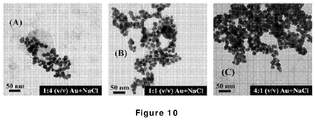
- the TEM images in the figures 10(A) - 10(C) show the AuNP in 4M NaCl at the proportions of, 1:4 (v/v), 1:1 (v/v), and 4:1 (v/v), respectively.
Landscapes
- Engineering & Computer Science (AREA)
- Power Engineering (AREA)
- Microelectronics & Electronic Packaging (AREA)
- Chemical & Material Sciences (AREA)
- Chemical Kinetics & Catalysis (AREA)
- Electrochemistry (AREA)
- Electrolytic Production Of Non-Metals, Compounds, Apparatuses Therefor (AREA)
Description
- The present invention relates to conversion of solar energy into electrical energy. More specifically, the present invention is directed to develop an economic, environment friendly, and biodegradable microfluidic energy for producing electrical current/energy by combining influence of the solar irradiation, surface plasmon resonance (SPR), and streaming potential.
- Tapping the diverse resources of renewable or non-renewable energies has been among the topmost priorities of the technological developments in the recent years owing to the explosive increase in energy demands of the modern society. In particular, the renewable energy sources are envisioned to develop a sustainable and energy efficient society. The economic, scalable, efficient, and eco-friendly renewable energy harvesters are tipped to replace most of the present generation energy harvesters. In particular, development of energy efficient and eco-friendly solar energy harvesters is among the topmost priorities owing to their natural abundance across the globe. The document
US7898096 B1 is a relevant prior art. - The journey of solar energy harvesters started with the invention of photovoltaic effect in 1839 [Ref: E. Becquerel (1839), Comptes Rendus, 9, 561-567] followed by the invention of the effects of light on the semiconducting materials such as selenium in 1873 [Ref: Nature 7, 303, 1873]. The first solid-state selenium based solar cell was the outcome of the pioneering work by Fritts [Ref: C. E. Fritts, (1883), American Journal of Science, 26, 465.], which was later revolutionized by the discovery of the photoelectric effect in early 1900 [Ref: A. Einstein, (1905), Annalen der Physik (ser. 4), 17, 132-148], where the interaction between the light and electrons were explained. Following this, many photo-sensitive devices were developed [Ref:, R. A. Millikan, (1914), Physical Review 4 (1), 73-75,
US Patent 2402662 ,US Patent 2524035 ,US Patent 2542115 ,US Patent 2641713 ,US Patent 2740901 ,US Patent 2757324 ] including the first experimental demonstration of the photoelectric effect [Ref: R. A. Millikan, (1914), Physical Review 4 (1), 73-75]. The first prototype of solar energy harvesters appeared much later in the 1950's with an efficiency ~ 4.5% [Ref:US Patent 2780765 ], which followed by a number of such devices with similar efficiencies [Ref:US Patent 2794863 ,US Patent 2873303 ]. The major challenges on the efficiencies in this era were partially resolved by Hoffman electronics showing a remarkable ~ 14% efficiency [Ref:US Patent 2938933 ]. Thereafter, different types of energy harvesting devices such as p-n junction, large-area, and electrochemical photovoltaic cells were developed [Ref:US Patent 3089070 ;US Patent 3370986 ;US Patent 3433677 ;US Patent 3984256 ;US Patent 4385102 ;US Patent 4471036 ;US Patent 4436558 ]. In 1985, the Center for Photovoltaic Engineering at the University of New South Wales unearthed the photovoltaic cells with -20% efficiency. In 2006, the 40% efficiency barrier was broken through multi-junction solar energy harvesters [Ref: R. King et al., (2007), Applied Physics Letter, 90, 183516; US Patent ApplicationUS 2010/0096001 A1 ]. However, most of the aforementioned developments on the solar cells were in the inorganic front and off late, scientists and technologists started realizing that large scale manufacturing of silicon based photovoltaic cells has issues associated with economic feasibility, biodegradability, and environmental friendliness. Thus, over the years, developments of different generations of solar cell technologies have been observed. - The first generation is based on silicon and demonstrates efficiency about 15-20% [Ref:
US Patent Application 2009/0038669 A1 ;US Patent Application 2011/0277813 A1 ;US Patent Application 2008/0078444 A1 ]. The silicon wafer based solar cells dominate the present day market due to their performance and stability although they suffer because of their lack of flexibility and large cost of production. The second generation photovoltaics are based on thin-films composed of materials such as, amorphous silicon, cadmium telluride or copper indium gallium diselenide, with typical efficiency ~ 10 - 15% [Ref:US Patent 5646050 ;US Patent Application 2008/0135083 A1 ] with a relatively lower cost of production. The third generation extensively uses smart materials, nanotechnology [Ref:US Patent application 2008/0169019 A1 ;US Patent Application 2008/0169017 A1 ] and polymers [Ref:US Patent Application 2009/0266418 A1 ;US Patent Application 2008/0023067 A1 ] such as the organic solar cells [Ref:US Patent Application 2005/0224905 A1 ;US Patent Application 2008/0264488 A1 ]. Polymer solar cells are inexpensive [Ref:US Patent Application 2009/0266418 A1 ;US Patent Application 2008/0023067 A1 ], flexible [Ref:US Patent 7053294 B2 ], and can be fabricated on roll-to-roll basis [Ref:US Patent Application 2011/0253982 A1 ;US Patent 6410362 B1 ] although face limitations associated with their stability and energy efficiency [Ref:US Patent Application 2003/0226498 A1 ]. This type of solar energy harvesters also covers multi-junction cells for improved performance although their commercial applicability is limited by high production cost [Ref:US Patent 6787692 B2 ;US Patent 6459034 B2 ]. Recently, the perovskite cells have recorded efficiencies beyond 20% [Ref:WO 2013/171520 A1 ] and are also under the process of commercialization [Ref:WO 2013/171520 A1 ]. - In view of the above, in the recent years, extensive efforts have been invested to develop electrochemical, photo-electrochemical, dye-sensitized, and nano-enabled photovoltaic cells [Ref:
US Patent 4816420 ;US Patent 5055416 ;US Patent 5084365 ;US Patent 5279678 ;WO 1996/008022 A1 ;WO 1997/035332 A1 ;WO 1997/015959 A1 ;WO 1998/005084 A1 ;WO 1999/063599 A1 ;US Patent 6028265 ;US Patent 6281429 B1 ;US Patent 6335480 B1 ;US Patent Application 2004/0025933 A1 ;US Patent 6913713 B2 ] composed of thin films, polymers, translucent materials and organic materials as a replacement of silicon based solar energy harvesters [Ref:US Patent Application 2007/0193621 A1 ;US Patent Application 2007/0240758 A1 ;US Patent Application 2008/0083448 A1 ;US Patent Application 2008/0236657 A1 ;US Patent Application 2009/0293950 A1 ;US Patent Application 2009/0229667 A1 ; US Patent ApplicationUS 2010/0089436 A1 ;CN 101840948 A ;CN 201616445 U ;US Patent 8071874 B2 ;US Patent Application 2012/0067422 A1 ;US Patent 8525021 B2 ;US Patent 8664514 B2 ;US Patent 8981214 B2 ]. The focus is mainly on the use of smart and economic materials at the micro or nano-scale to bring in the specialties of nano-science and technology for lower cost of production, flexibility, portability, rapidness, bio-degradability, energy efficiency, environment friendliness, scalability, and stability. - Of particular interest here, is the Cu-Cu2O system for solar energy harvesting employing a microfluidic energy harvester (MEH). The metal oxide Cu2O is well known for its p-type semiconducting properties with a band gap of ~ 2 eV and relatively higher absorption coefficient in the visible region, which is suitable for solar energy harvesting [Ref:
US Patent 3376163A ;US Patent 4267398A ]. In the past, verities of solar cells have been constructed using Cu2O, for example, metal/p-Cu2O, n-ZnO/p-Cu2O, or n-CdO/p-Cu2O. Among these devices, the previous Cu/Cu2O solar cells have shown maximum reported efficiency -2% [Ref: T. Minami et. al., (2011), Applied Physics Express, 4, 062301]. The Cu-Cu2O systems also have advantages in lower production cost, nontoxic, relatively high minority carrier diffusion length, and the theoretical limit of efficiency of ~ 20% [Ref: L. C. Olsen et. al. (1979), Applied Physics Letter, 34, 1]. Interestingly, the Cu2O energy harvesters show higher efficiencies in the yellow to near UV region where the efficiency of the silicon energy harvesters is rather low. - In the recent past, a number of works have developed different kinds of MEH where the mechanical energy was converted to the electrical one for energy harvesting [Ref:
US Patent 7898096 B1 ]. In particular, the flow inside microfluidic devices open up the possibility of the continuous conversion of mechanical energy into the electrical one, which are in general done by the hydel power generators at the macroscopic scale [Ref:US Patent 7898096 B1 ;US Patent Application 2012/0181901 A1 ]. The MEHs generating high power density from the variations in the zeta potential due to droplet actuation [Ref: J. K. Moon et. al., (2013), Nature Communication, 4, 1487], reverse electro-wetting [Ref: T. Krupenkin et. al., (2011), Nature Communication, 2, 448], or piezoelectric properties inside a microdevice [Ref:US2004/0075363 A1 ] have already been reported in the literature. The reported MEHs employ the specialties of nanoscience and nanotechnology to improve the efficiency of energy harvesting and power density [Ref: J. K. Moon et. al., (2013), Nature Communication, 4, 1487; T. Krupenkin et. al., (2011), Nature Communication, 2, 448]. For example, the specialties of nanowires [Ref:US Patent 9299866 B2 US Patent Application 2014/0352784 A1 ], or nanotubes [Ref:US Patent 9013092 B2 US Patent 7687977 B2 ] have shown their importance in binding the solar irradiation through higher absorptivity [Ref:WO 2007/149001 A2 ] as well as enhancement of the electron-hole transport due to larger electrical conductivity [refer to,WO 2011/139655 A1 ]. Further, enhancement of efficiency and performance of the energy harvesters with the surface plasmon resonance (SPR) of the nanoscale objects such as wires, particles, or fibers have also been shown in the recent past [Ref:WO2015/038203 A1 ]. Importantly, MEHs are equally efficient in converting the different other forms of energies into electrical one [Ref: J. K. Moon et. al., (2013), Nature Communication, 4, 1487; T. Krupenkin et. al., (2011), Nature Communication, 2, 448] because the power density of many of the conventional macroscopic processes [Ref: J. A. Paradiso et. al., (2005), IEEE CS and IEEE Communications Society Pervasive computing, 5, 1536-1268] such as radio frequency (∼ 1 W/cm2), solar irradiation (∼ 100 mW/cm2), ambient illumination (∼ 100 W/cm2), thermoelectric (∼ 60 W/cm2) or vibration generators (∼ 10 - 800 W/cm3), or ambient air flow (∼ 1 mW/cm2) have been found to be comparable with the recently developed MEHs [refer to, J. K. Moon et. al., (2013), Nature Communication, 4, 1487]. A very large scale integration of the MEHs is envisioned to surpass the performance of the similar macroscopic devices and supply energy to diverse modern day gadgets such as mobile phones, tablets, laptops, or display units, in the near future. - It is thus the basic object of the present invention is to develop a microchannel based microfluidic energy harvester which is portable, can be made flexible to rigid, economic, eco-friendly and capable of producing high density electrical energy to supply energy for a wide range of electronic applications like mobile phones, computers, biomedical or healthcare appliances, and fabrication/characterization instruments.
- Another object of the present invention is to develop a microfluidic energy harvester adapted to be designed with commonly available materials and fabricated without employing any costly equipment for fabrication and integration.
- Yet another object of the present innovation is to develop an electrolyte based microfluidic energy harvester which would be adapted to bind solar energy when illuminated under direct solar irradiation and generate electrical energy by using the solar energy.
- Another object of the present innovation is to develop an electrolyte based microfluidic energy harvester which would be adapted to amplify electrical energy generation by combining influence of the solar irradiation with surface plasmon resonance (SPR), and streaming potential.
- Thus according to basic aspect of the present invention there is provided a microfluidic energy harvester for converting solar energy into electrical energy comprising a substrate and as recited in
claim 1. - According to another aspect in the present microfluidic energy harvester for converting solar energy into electrical energy, each of the pair of electrodes includes a conducting metal electrode and a semiconducting metal-oxide electrode having adequate bandgap to bind the solar energy under direct solar illumination.
- According to yet another aspect in the present microfluidic energy harvester for converting solar energy into electrical energy, the substrate includes a transparent slab of polymer preferably poly-dimethylsiloxane embedding the central microchannel having an inlet and an outlet;
said substrate includes plurality of tributary microchannels arranged in series and perpendicular to the central microchannel on both the sides, each of the tributary microchannels is connected to the central microchannel and includes provision for inserting the conducting metal and/or the semiconducting metal-oxide electrode enabling the electrodes to be in contact with the electrolyte residing and/or flowing in the central microchannel without touching each other. - According to another aspect in the present microfluidic energy harvester for converting solar energy into electrical energy, the semiconducting metal-oxide electrodes include Cu2O electrodes inserted in the tributary microchannels in one side of the main microchannel and the conducting metal electrodes include Cu electrodes inserted in the tributary microchannels in other side of the central microchannel ensuring the electrodes from both the sides do not touch each other and each of the electrodes touches the electrolyte residing and/or flowing in the central microchannel.
- According to a further aspect in the present microfluidic energy harvester for converting solar energy into electrical energy, the electrolyte preferably includes suspension of aqueous 4.0M NaCl solution with 20% (v/v) metallic nanoparticle (AuNP) concentration.
- According to another aspect in the present microfluidic energy harvester for converting solar energy into electrical energy, the electrochemical photovoltaic unit generated electrochemical photovoltaic potential is
- According to yet another aspect in the present microfluidic energy harvester for converting solar energy into electrical energy, the streaming potential generated due to the electrolyte flow is

- According to another aspect in the present microfluidic energy harvester for converting solar energy into electrical energy, the enhancement of potential due to the SPR is USPR = nabsUECPV , where nabs is fraction of optical absorption increased due to the SPR.
- According to another aspect in the present microfluidic energy harvester for converting solar energy into electrical energy, the conversion of the solar energy into the electrical energy due to the electrochemical photovoltaic effect under direct solar illumination by working under regenerative conditions includes
generation of electron-hole pairs or excitons under direct solar illumination wherein electrons from valance band of the semiconductor electrodes jumped to conduction band, leaving a hole behind;
transferring of the electron to cations of redox couples present in the electrolyte;
simultaneous transferring of the hole to the metal electrode through external circuit and oxidizing anions of the redox couple in the electrolyte. -
-
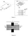
Figure 1 show (A) isometric (B) side and (C) front views of a preferred embodiment of present microfluidic energy harvester. -
Figure 2 shows the different cross sectional views of the present microfluidic energy harvester embodiment. -
Figure 3 shows different views of the present microfluidic energy harvester embodiment's constructional elements. -
Figure 4 shows different cross-sectional views of the present microfluidic energy harvester embodiment's constructional elements. -
Figure 5 shows block representation of the present microfluidic energy harvester embodiment. -
Figure 6 show photographic illustration of the present microfluidic energy harvester (A) and (B); variation of voltage generation involving the present microfluidic energy harvester (C); variations in maximum generated voltage (V gmax), current density (J gmax) and power density (P D) for different operating condition involving the present microfluidic energy harvester (D) and (E). -
Figure 7 show optimization of flow rate of the present microfluidic energy harvester for maximum output, with and without AuNPs: change in maximum generated voltage (V gmax), current density (J gmax), and power density (P D) for 4M NaCl solution at different flow rates with 9 electrodes (A)-(C); change in maximum generated voltage (V gmax), current density (J gmax), and power density (P D) for 4M NaCl solution with 20% of AuNPs concentration at different flow rates with 9-pair electrodes (D)-(F). -
Figure 8 show (A) comparison of theoretical and experimental output and (b) efficiency calculation for optimized flow-rate and AuNP concentration in accordance with the present microfluidic energy harvester. -
Figure 9 (A)-(F) show characterizations of AuNPs and Cu-Cu2O electrodes in accordance with the present microfluidic energy harvester. -
Figure 10 show agglomeration of AuNPs at different concentration of AuNPs in 4M NaCl in accordance with the present microfluidic energy harvester. - As stated hereinbefore the present invention discloses a novel microfluidic energy harvester (MEH) which is configured to convert solar energy into electrical energy and amplify voltage generated from the solar energy by involving surface plasmon resonance (SPR) and/or streaming potential.
- The microfluidic energy harvester of the present invention includes a polymer substrate in which a microchannel is embedded for the flow of electrolyte. The microchannel is integrated with an electrode assembly from the sides. The electrode assembly includes one or more pair of electrodes arranged in a series wherein each pair for electrodes includes a conducting metal and a semiconducting metal-oxide electrode. The metal/semiconducting metal-oxide electrodes combination is chosen in such a manner that they had just adequate bandgap to bind solar energy under direct solar illumination.
- In a preferred embodiment, the electrolyte includes a suspension of salt-water and metal nanoparticles and configured reside and/or flow in the central microchannel with the help of hydrostatic head at a constant flow rate. The metal nanoparticles and their size and the shape are selected in such a manner that they are capable of producing SPR under direct solar illumination.
- During flow of the electrolyte through the microchannel, the metal/semiconducting metal-oxide electrodes come in direct contact with the electrolyte suspended with nanoparticles. The contact of the electrolyte with the electrodes not only ensure easy flow of current because of the voltage generated by the solar energy and SPR but also the arrangement facilitates conversion of mechanical energy of the electrolyte flow into the streaming potential across the electrodes. Thus, under direct solar illumination, when the electrolyte suspended with metal nanoparticles is flown inside the microchannel of the present microfluidic energy harvester, the electrodes show a potential difference equivalent to the combined influences from the solar energy, SPR, and streaming potential.
- Reference is first invited from the accompanying
figure 1(A)-(C) and 2 which show a preferred embodiment of the present microfluidic energy harvester and its different cross sectional views respectively. As shown in the referred figures, thepolymer substrate 101 which preferably includes acentral microchannel 103 embedded inside a transparent slab of poly-dimethylsiloxane. One ends of thecentral microchannel 103 is used as inlet and other end of thecentral microchannel 103 is used as outlet. A series of tributary microchannels 102 are also fabricated in perpendicular to thecentral microchannel 103 on both the sides. Each of the tributary microchannels 102 is connected to thecentral microchannel 103 and includes provision for inserting the metal and/or metal-oxide electrode. - Reference next invited from the accompanying
figure 3 , which shows different views of the present microfluidic energy harvester embodiment's constructional elements. The microfluidic energy harvester's substrate with integrated electrodes is demonstrated in thefigure 3 in which multiple metal/ semiconducting metal-oxide electrodes 104 are inserted within the tributary microchannels 102 from the sides. The accompanyingfigure 4 shows the cross-sectional image of the microfluidic energy harvester's substrate with integrated electrodes as shown in thefigure 3 . - The
electrodes 104 of the present microfluidic energy harvester preferably include a selective combination of metal and semiconducting metal-oxide electrodes having adequate band-gap to bind the solar energy under direct solar irradiation. In a preferred embodiment, the semiconducting metal-oxide electrodes include Cu2O electrode whereas, the metal electrodes include Cu electrodes. - The arrangement of the electrodes include disposition of the Cu2O electrodes inserted in the tributary microchannels 102 in one side of the
main microchannel 103 and cooperative disposition of the Cu electrodes inserted in the tributary microchannels 102 in other side of thecentral microchannel 103 ensuring electrodes from both the sides do not touch each other and each of the electrodes touches flow of the electrolyte through themain microchannel 103. The arrangement is described in detail in thefigure 4 . - Reference is next invited from the accompanying
figure 5 which shows a block representation of the present microfluidic energy harvester where the electrolyte is flow through the central microchannel of effective diameter of d and length L. The electrodes are inserted from the sides of the channel. The streaming potential for such an energy harvester is
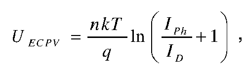
- The electrochemical photovoltaic potential is calculated employing the expression,

- The enhancement of potential due to SPR is evaluated from the expression USPR = nabsUECPV ...(3), where nabs is fraction of optical absorption increased due to SPR.
- Combining all the aforementioned potentials as expressed in the Eqn, (1), (2) and (3), the total voltage which could be generated by the microfluidic energy harvester will be,

- Fill-factor (FF) and power efficiency ( ) can also be evaluated for the present microfluidic energy harvester by employing the expressions,


- In a preferred embodiment of the present invention, the metal nanoparticles of the electrolyte which preferably include Au nanoparticles (AuNPs) is synthesized by sodium borohydride (NaBH4) reduction method of auric chloride (HAuCl4.3H2O) salt [refer to, Martin et al., Langmuir 2010, 26, 7410-7417]. Initially, a 50mM aqueous solution of AuCl4- (solution I) is mixed with hydrochloric acid (HCI) in equal molar ratio. Following this, a 50mM of BH4- solution (solution II) is prepared by dissolving NaBH4 in aqueous 1mM sodium hydroxide (NaOH) in equal molar ratio. Thereafter, 100 µl of solution I is mixed with water to obtain a solution where the concentration of gold ions is 0.5mM. Then, 300 µl solution II is mixed with solution I with continuous stirring. The AuNPs formed as the change in color took place from yellow to orange and then to red. The AuNP suspensions are mixed with 4.0 M NaCl solution (v/v) at different proportion to prepare the electrolyte suspensions having different amount of nanoparticles.
- Reference is next invited from the accompanying
figure 6(A)-(E) , wherein thefigure 6(A) and 6(B) shows photographic illustration of the present microfluidic energy harvester and thefigure 6(C)-6(E) shows the combined effect of electrochemical photovoltaics, streaming potential and surface plasmon resonance in the present microfluidic energy harvester in respect to convert solar energy into electrical energy. - The electrolyte used in the present microfluidic energy harvester is a 4.0 M NaCl (234 gm/L) aqueous solution with suspended Au nanoparticle which is pumped into the inlet of the central microchannel (103) with the help of hydrostatic head or micro-pumps. During the flow through the central microchannel, the electrolyte comes in contact with the semiconducting and metal electrodes (104) inside the microfluidic energy harvester and generates voltage under the exposure of the sunlight.
- The combination of semiconductor (e.g. Cu2O) electrodes, electrolyte (NaCl solution) and metal counter electrodes (e.g. Cu) within the microfluidic energy harvester constitute electrochemical photovoltaic (ECPV) units across the microfluidic energy harvester. These ECPV units generate electron-hole pairs or excitons under direct solar illumination in which electrons from valance band of the semiconductor electrodes jump to the conduction band, leaving a hole behind. The created electron is then transferred to the cations of the redox couples present in the electrolyte (e.g. Na+). Consequently, the holes reached the Cu counter electrode through the external circuit and oxidized the anions (Cl-) of the redox couple in the electrolyte. Since there is no net consumption of material in the electrolyte due to this process, the ECPV units work under regenerative conditions.
- The voltage generation inside the present microfluidic energy harvester can be categorized in three parts depending on their origins. The plots as shown in the
figure 6(C) illustrates the voltage generation for a 9-pair electrodes based microfluidic energy harvester due to (i) only electrochemical photovoltaic effect where a stationary electrolyte which include 4.0M NaCl solution is exposed to the sunlight, (ii) electrochemical photovoltaic effect along with streaming potential for a flowrate of F R = 0.01 ml/min of the electrolyte which include 4.0M aqueous NaCl solution through the central microchannel under the exposure of the sunlight and (iii) combined effect of electrochemical photovoltaic effect, streaming potential, and surface plasmon resonance for a flowrate F R = 0.01 ml/min of the electrolyte which include a suspension of 4.0M aqueous NaCl solution and 20% (v/v) metallic nanoparticle (AuNP) concentration through the central microchannel. - From the plot (C), it would be apparent that there is a productive effect of flow and SPR in energy harvesting utilizing the sunlight. Further experiments are performed to measure the change in maximum generated voltage (V gmax) and current density (J gmax) with different concentration (C Au) of AuNPs for the 9-pair electrodes system with a flow rate F R = 0.01 ml/min and effective light intensity of 1.1 kLux. The results of V gmax and J gmax were plotted in
figure 6(D) while thefigure 6(E) shows the change in power density (P D) for this device with different concentration of AuNPs (C Au). It is clear from plots under 6(D) and 6(E), that 20% (v/v) AuNPs is the optimum concentration for SPR to get the best performance, under the aforementioned conditions. After optimization of AuNP concentration, experiments are performed to optimize the flow rate (F R) of the electrolyte. For this purpose, the maximum generated voltage (V gmax), current density (J gmax), and power density (P D) are measured at different light intensities for different flow rates with and without AuNPs as shown in the accompanyingfigures 7(A)-7(F) . - The plots in
figures 7(A)-7(C) and 7(D)-7(F) show the maximum generated voltage (V gmax), current density (J gmax) and power density (P D) of the present microfluidic energy harvester for different flow rates (F R) of 4.0M NaCl solution at different intensities of the light without and with 20% (v/v) AuNPs, respectively. In the situations with and without AuNPs, the optimum flow rate is found to be F R ∼0.025 ml/min. - The plots in
figures 7(A)-7(C) and 7(D)-7(F) clearly show that the generated voltage (V gmax), current density (J gmax) and power density (P D) of the present microfluidic energy harvester are significantly enhanced due to the introduction of the AuNPs in the electrolyte solution. The figures also suggest that at higher flow rates of the electrolyte, the generated voltage is less because the partial destruction of electrical double layer (EDL) due to the flow near the electrodes. Moreover, mobility of electrons and holes should be too high to support the recombination of excitons. However, in case of higher flow rates the retention time of the redox species near the semiconductor surface abruptly decreases leading to a higher recombination in the system as the excitons do not get enough time to perform the redox reaction which in turn reduce the maximum generated voltage. - Reference is next invited from the accompanying
figures 8(A) and 8(B) which show comparison between theoretical and experimental studies and efficiencies of the present microfluidic energy harvester with different electrolyte viz. (I) stationary NaCl solution, (II) NaCl solution with flow, and (III) AuNPs in NaCl suspension flowing at optimized conditions (i.e. F R = 0.025 ml/min and C Au = 20% (v/v)), respectively. - For theoretical calculation of the streaming potential, it is assumed that width of the central microchannel (L) is 0.05 m, effective diameter of the central microchannel (d) is 10-4 m, the specific electrical conductivity (KL ) of the electrolyte is 0.015 S m-1, the flow rate of the electrolyte (F R) is (4.17x10⁻¹⁰) m3 s-1, dielectric constant of water (ε r ) is 80, dielectric permittivity of free space (ε0) is 8.854x10⁻¹² F m-1, and the zeta-potential of the electrodes (ζ) are 0.03 V. Plugging the values into the eqn. 1 the theoretical value for the USP can be obtain equal to 12.04 mV. The experimental value of the USP = 15 mV, is obtained by simply flowing the electrolyte inside the channel and then measuring the potential difference between the electrodes through a digital multi-meter.
- Similarly, for theoretical calculation of the electrochemical photovoltaic potential, it is assumed that, the ideality factor (n) is 1, Boltzmann constant (k) is 1.38 × 10⁻²³ m2 kg s-2 K-1, the absolute temperature (T) is 300 K, charge of electron (q) is 1.6 x 10⁻⁹ C, the current in presence of light (I ph) is 5.4 A, and the current in the dark (I D) is 0.3 A. Plugging the values into the eqn 2, the theoretical value for the UECPV can be obtained equal to 76.5 mV. The experimental value of the UECPV = 73 mV, is obtained by illuminating the stationary salt-water electrolyte and then measuring the potential difference between the electrodes through a digital multi-meter.
- The theoretical value of the SPR potential is obtained as USPR = 30.6 mV. In order to check the effect of SPR, an absorption spectroscopy is performed keeping the volume of the AuNPs constant, which provided the amount of absorption in the electrolyte suspension with different AuNP loading. The average absorption is calculated for a full spectral range and is found to be about 40% when the AuNP loading in the electrolyte is about 20% (v/v). The experimental value of the USPR = 27 mV, is obtained by illuminating the stationary AuNP loaded salt-water electrolyte, then measuring the potential difference between the electrodes through a digital multi-meter, and thereafter subtracting the experimental value of the UECPV from the multi-meter reading.
- Combining all the aforementioned theoretical potentials, the total theoretical value of the voltage, which could be generated by the MEH as,


figure 8(A) shows a typical comparison between theoretical values evaluated and experimental values measured for the reported MEH. - The fill-factor (FF) and power efficiency ( ) are also evaluated for the MEH employing the expressions,
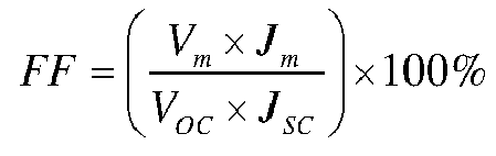

Figure 8(C) shows the typical variations in the power efficiency ( ) for the MEH (I) salt-water electrolyte is stationary, (II) when the salt-water electrolyte is flown at an optimum flow rate, and (III) when the salt-water electrolyte with suspended AuNPs (20% v/v) is flown at an optimum flow rate. - The following Table 1 shows the typical theoretical and experimental values evaluated during these calculations for the MEHs (I) - (III).
Table I System Voc(mV) JSC (mA/cm2) Vm (mV) Jm (mA/cm2) FF% η% I. Stationary Salt-water Electrolyte 68.6 0.91 42.4 0.6 41.06 ∼ 0.35 II. Flowing Salt-water Electrolyte 79.4 1.17 48 0.86 44.29 ∼ 0.56 III. Flowing Electrolyte with AuNPs 106.3 1.78 83.7 1.49 65.91 ∼1.71 - Reference is now invited from the accompanying
figure 9 and10 which show the typical characterizations of the AuNPs and Cu-Cu2O electrodes. Thefigures 9(A) and 9(B) show the TEM image and SAED pattern of the synthesized AuNPs andfigure 9(C) shows the EDX of AuNPs. Thefigure 9(D) shows the FESEM image of grown Cu2O film. The cross-sectional FESEM image [figure 9(E) ] of the electrode shows the thickness of the Cu2O layer andfigure 9 (F) shows the EDX of the Cu2O film. The TEM images in thefigures 10(A) - 10(C) show the AuNP in 4M NaCl at the proportions of, 1:4 (v/v), 1:1 (v/v), and 4:1 (v/v), respectively.
Claims (9)
- A microfluidic energy harvester for converting solar energy into electrical energy comprising
a substrate (101) having an embedded central microchannel (103);
electrolyte in said central microchannel;
electrode assembly having at least one pair of electrodes (104) arranged in series and integrated with said central microchannel from sides ensuring direct contact between said pair of electrodes with said electrolyte in said central microchannel for ensuing electrochemical photovoltaic effect to convert the solar energy into the electrical energy under solar illumination under regenerative conditions, wherein the electrolyte is configured to flow in the central microchannel through the inlet by using hydrostatic head or micro-pump at a constant flow rate enabling conversion of mechanical energy of the electrolyte flow into streaming potential across the electrodes and showing a potential difference equivalent to combined influences from the solar energy and the streaming potential resulting in amplification of the electrical energy generation, and wherein the electrolyte includes a suspension of salt-water and metal nanoparticles capable of producing surface plasmon resonance (SPR) under direct solar illumination when it flows through the central microchannel which enhances potential difference across the electrodes and generates the potential difference equivalent to combined influences from the solar energy, the streaming potential and the surface plasmon resonance resulting in further amplification of the electrical energy generation. - A microfluidic energy harvester for converting solar energy into electrical energy as claimed in claim 1, wherein each of the pairs of electrodes includes a conducting metal electrode and a semiconducting metal-oxide electrode having adequate bandgap to bind the solar energy under direct solar illumination.
- A microfluidic energy harvester for converting solar energy into electrical energy as claimed in anyone of claim 1 or 2, wherein the substrate includes a transparent slab of polymer preferably poly-dimethylsiloxane embedding the central microchannel having an inlet and an outlet;
said substrate includes plurality of tributary microchannels (102) arranged in series and perpendicular to the central microchannel on both the sides, each of the tributary microchannels is connected to the central microchannel and includes provision for inserting the conducting metal and/or the semiconducting metal-oxide electrode enabling the electrodes to be in contact with the electrolyte residing and/or flowing in the central microchannel without touching each other. - A microfluidic energy harvester for converting solar energy into electrical energy as claimed in anyone of claims 1 to 3, wherein the semiconducting metal-oxide electrodes include Cu2O electrodes inserted in the tributary microchannels in one side of the main microchannel and the conducting metal electrodes include Cu electrodes inserted in the tributary microchannels in other side of the central microchannel ensuring the electrodes from both the sides do not touch each other and each of the electrodes touches the electrolyte residing and/or flowing in the central microchannel.
- A microfluidic energy harvester for converting solar energy into electrical energy as claimed in anyone of claims 1 to 4, wherein the electrolyte preferably includes suspension of aqueous 4.0M NaCl solution with 20% (v/v) metallic nanoparticle (AuNP) concentration.
- A microfluidic energy harvester for converting solar energy into electrical energy as claimed in anyone of claims 1 to 5, wherein the electrochemical photovoltaic unit generated electrochemical photovoltaic potential is

- A microfluidic energy harvester for converting solar energy into electrical energy as claimed in anyone of claims 1 to 6, wherein the streaming potential generated due to the electrolyte flow is

- A microfluidic energy harvester for converting solar energy into electrical energy as claimed in anyone of claims 1 to 7, wherein the enhancement of potential due to the SPR is USPR = nabsUECPV, where nabs is fraction of optical absorption increased due to the SPR.
- A microfluidic energy harvester for converting solar energy into electrical energy as claimed in anyone of claims 1 to 8, wherein the conversion of the solar energy into the electrical energy due to the electrochemical photovoltaic effect under direct solar illumination by working under regenerative conditions includes generation of electron-hole pairs or excitons under direct solar illumination wherein electrons from valence band of the semiconductor electrodes jumped to conduction band, leaving a hole behind;
transferring of the electron to cations of redox couples present in the electrolyte; simultaneous transferring of the hole to the metal electrode through external circuit and oxidizing anions of the redox couple in the electrolyte.
Applications Claiming Priority (2)
| Application Number | Priority Date | Filing Date | Title |
|---|---|---|---|
| IN201631036408 | 2016-10-24 | ||
| PCT/IN2017/050364 WO2018078642A1 (en) | 2016-10-24 | 2017-08-29 | A microfluidic electrical energy harvester |
Publications (3)
| Publication Number | Publication Date |
|---|---|
| EP3375017A1 EP3375017A1 (en) | 2018-09-19 |
| EP3375017A4 EP3375017A4 (en) | 2019-07-31 |
| EP3375017B1 true EP3375017B1 (en) | 2021-08-11 |
Family
ID=62024504
Family Applications (1)
| Application Number | Title | Priority Date | Filing Date |
|---|---|---|---|
| EP17863346.7A Active EP3375017B1 (en) | 2016-10-24 | 2017-08-29 | A microfluidic electrical energy harvester |
Country Status (3)
| Country | Link |
|---|---|
| US (1) | US11189432B2 (en) |
| EP (1) | EP3375017B1 (en) |
| WO (1) | WO2018078642A1 (en) |
Families Citing this family (4)
| Publication number | Priority date | Publication date | Assignee | Title |
|---|---|---|---|---|
| US10559864B2 (en) | 2014-02-13 | 2020-02-11 | Birmingham Technologies, Inc. | Nanofluid contact potential difference battery |
| US11649525B2 (en) | 2020-05-01 | 2023-05-16 | Birmingham Technologies, Inc. | Single electron transistor (SET), circuit containing set and energy harvesting device, and fabrication method |
| US11417506B1 (en) | 2020-10-15 | 2022-08-16 | Birmingham Technologies, Inc. | Apparatus including thermal energy harvesting thermionic device integrated with electronics, and related systems and methods |
| US11616186B1 (en) | 2021-06-28 | 2023-03-28 | Birmingham Technologies, Inc. | Thermal-transfer apparatus including thermionic devices, and related methods |
Family Cites Families (80)
| Publication number | Priority date | Publication date | Assignee | Title |
|---|---|---|---|---|
| US2402662A (en) | 1941-05-27 | 1946-06-25 | Bell Telephone Labor Inc | Light-sensitive electric device |
| US2542115A (en) | 1948-01-30 | 1951-02-20 | Fay C Brown | Photosensitive device |
| US2524035A (en) | 1948-02-26 | 1950-10-03 | Bell Telphone Lab Inc | Three-electrode circuit element utilizing semiconductive materials |
| US2641713A (en) | 1951-03-21 | 1953-06-09 | Bell Telephone Labor Inc | Semiconductor photoelectric device |
| US2794863A (en) | 1951-07-20 | 1957-06-04 | Bell Telephone Labor Inc | Semiconductor translating device and circuit |
| US2740901A (en) | 1951-12-29 | 1956-04-03 | Bell Telephone Labor Inc | Differential photocell detector using junction semiconductors |
| BE517459A (en) | 1952-02-07 | |||
| NL192903A (en) | 1954-03-05 | |||
| US2873303A (en) | 1954-11-01 | 1959-02-10 | Philips Corp | Photovoltaic device |
| US3089070A (en) | 1957-09-03 | 1963-05-07 | Hoffman Electronics Corp | Photoelectric converter or the like |
| US2938933A (en) | 1958-07-30 | 1960-05-31 | American Oil Co | Synthesis of aromatic hydrocarbons |
| US3376163A (en) | 1961-08-11 | 1968-04-02 | Itek Corp | Photosensitive cell |
| US3370986A (en) | 1963-12-10 | 1968-02-27 | Westinghouse Electric Corp | Photovoltaic series array comprising p/n and n/p cells |
| US3433677A (en) | 1967-04-05 | 1969-03-18 | Cornell Aeronautical Labor Inc | Flexible sheet thin-film photovoltaic generator |
| US3984256A (en) | 1975-04-25 | 1976-10-05 | Nasa | Photovoltaic cell array |
| US4267398A (en) | 1979-05-29 | 1981-05-12 | University Of Delaware | Thin film photovoltaic cells |
| DE3177084D1 (en) | 1980-04-10 | 1989-09-21 | Massachusetts Inst Technology | Method of producing sheets of crystalline material |
| DE3013991A1 (en) | 1980-04-11 | 1981-10-15 | Bayer Ag, 5090 Leverkusen | LARGE-SCALE PHOTOVOLTAIC CELL |
| US4436558A (en) | 1980-12-15 | 1984-03-13 | The United States Of America As Represented By The United States Department Of Energy | Electrochemical photovoltaic cell having ternary alloy film |
| US4471036A (en) | 1983-06-29 | 1984-09-11 | The United States Of America As Represented By The United States Department Of Energy | Electrochemical photovoltaic cells and electrodes |
| CH674596A5 (en) | 1988-02-12 | 1990-06-15 | Sulzer Ag | |
| US5055416A (en) | 1988-12-07 | 1991-10-08 | Minnesota Mining And Manufacturing Company | Electrolytic etch for preventing electrical shorts in solar cells on polymer surfaces |
| US5279678A (en) | 1992-01-13 | 1994-01-18 | Photon Energy, Inc. | Photovoltaic cell with thin CS layer |
| WO1995026571A1 (en) | 1994-03-25 | 1995-10-05 | Amoco/Enron Solar | Stabilized amorphous silicon and devices containing same |
| SE9402940D0 (en) | 1994-09-02 | 1994-09-02 | Solaronix Sa | Electrochemical photovoltaic cell |
| WO1997015959A1 (en) | 1995-10-24 | 1997-05-01 | Isa Ag Arch | Method for making an electrochemical cell, and resulting electrochemical cell |
| AU2090197A (en) | 1996-03-20 | 1997-10-10 | Ecole Polytechnique Federale De Lausanne | Electrochemical device and electrolyte therefor |
| AUPO129496A0 (en) | 1996-07-26 | 1996-08-22 | Broken Hill Proprietary Company Limited, The | Photoelectrochemical cell |
| JP4174842B2 (en) | 1996-12-16 | 2008-11-05 | 富士ゼロックス株式会社 | Photo-semiconductor electrode, photoelectric conversion device, and photoelectric conversion method |
| DE19711713A1 (en) | 1997-03-20 | 1998-10-01 | Hoechst Ag | Photovoltaic cell |
| SE9801799D0 (en) | 1998-05-20 | 1998-05-20 | Sten Eric Lindquist | Dye sensitized nanostructured photovoltaic tandem cell |
| JP2001148491A (en) | 1999-11-19 | 2001-05-29 | Fuji Xerox Co Ltd | Photoelectric conversion element |
| US20030192585A1 (en) | 2002-01-25 | 2003-10-16 | Konarka Technologies, Inc. | Photovoltaic cells incorporating rigid substrates |
| US6913713B2 (en) | 2002-01-25 | 2005-07-05 | Konarka Technologies, Inc. | Photovoltaic fibers |
| US6900382B2 (en) | 2002-01-25 | 2005-05-31 | Konarka Technologies, Inc. | Gel electrolytes for dye sensitized solar cells |
| JP2002057359A (en) | 2000-06-01 | 2002-02-22 | Sharp Corp | Stacked solar cell |
| US6410362B1 (en) | 2000-08-28 | 2002-06-25 | The Aerospace Corporation | Flexible thin film solar cell |
| US6787692B2 (en) | 2000-10-31 | 2004-09-07 | National Institute Of Advanced Industrial Science & Technology | Solar cell substrate, thin-film solar cell, and multi-junction thin-film solar cell |
| US7053294B2 (en) | 2001-07-13 | 2006-05-30 | Midwest Research Institute | Thin-film solar cell fabricated on a flexible metallic substrate |
| US7777303B2 (en) | 2002-03-19 | 2010-08-17 | The Regents Of The University Of California | Semiconductor-nanocrystal/conjugated polymer thin films |
| US6858970B2 (en) | 2002-10-21 | 2005-02-22 | The Boeing Company | Multi-frequency piezoelectric energy harvester |
| IL153895A (en) * | 2003-01-12 | 2013-01-31 | Orion Solar Systems Ltd | Solar cell device |
| US20050224905A1 (en) | 2004-04-13 | 2005-10-13 | Forrest Stephen R | High efficiency organic photovoltaic cells employing hybridized mixed-planar heterojunctions |
| US20070193621A1 (en) | 2005-12-21 | 2007-08-23 | Konarka Technologies, Inc. | Photovoltaic cells |
| US20080023067A1 (en) | 2005-12-27 | 2008-01-31 | Liangbing Hu | Solar cell with nanostructure electrode |
| US7687977B2 (en) | 2006-04-10 | 2010-03-30 | Honeywell International Inc. | Micromachined, piezoelectric vibration-induced energy harvesting device and its fabrication |
| US20070240758A1 (en) | 2006-04-14 | 2007-10-18 | Thomas Spartz | Double-sided solar module |
| DE102006023638A1 (en) | 2006-05-18 | 2007-11-22 | Sefar Ag | Photovoltaic cell |
| US7928317B2 (en) | 2006-06-05 | 2011-04-19 | Translucent, Inc. | Thin film solar cell |
| WO2007149001A2 (en) | 2006-06-19 | 2007-12-27 | Corneliu Antonovici | Method and structure for solar energy harvesting type glass roof tile |
| US20090038669A1 (en) | 2006-09-20 | 2009-02-12 | Translucent Photonics, Inc. | Thin Film Solar Cell III |
| US20080083448A1 (en) | 2006-09-29 | 2008-04-10 | Borden Peter G | Interconnect for thin film photovoltaic modules |
| US20080135083A1 (en) | 2006-12-08 | 2008-06-12 | Higher Way Electronic Co., Ltd. | Cascade solar cell with amorphous silicon-based solar cell |
| US7977568B2 (en) | 2007-01-11 | 2011-07-12 | General Electric Company | Multilayered film-nanowire composite, bifacial, and tandem solar cells |
| US8003883B2 (en) | 2007-01-11 | 2011-08-23 | General Electric Company | Nanowall solar cells and optoelectronic devices |
| JP5649954B2 (en) | 2007-04-02 | 2015-01-07 | メルク パテント ゲーエムベーハー | Articles configured as photovoltaic cells |
| WO2008134492A1 (en) | 2007-04-27 | 2008-11-06 | Konarka Technologies, Inc. | Organic photovoltaic cells |
| US7898096B1 (en) * | 2007-08-22 | 2011-03-01 | Thomas Nikita Krupenkin | Method and apparatus for energy harvesting using microfluidics |
| WO2009042125A1 (en) | 2007-09-25 | 2009-04-02 | First Solar, Inc. | Photovoltaic devices including heterojunctions |
| WO2009142787A2 (en) | 2008-02-18 | 2009-11-26 | Board Of Regents, The University Of Texas System | Photovoltaic devices based on nanostructured polymer films molded from porous template |
| US20090229667A1 (en) | 2008-03-14 | 2009-09-17 | Solarmer Energy, Inc. | Translucent solar cell |
| EP2172986B1 (en) * | 2008-08-27 | 2013-08-21 | Honeywell International Inc. | Solar cell having hybrid hetero junction structure |
| US9299866B2 (en) | 2010-12-30 | 2016-03-29 | Zena Technologies, Inc. | Nanowire array based solar energy harvesting device |
| WO2010036807A1 (en) | 2008-09-24 | 2010-04-01 | The Board Of Trustees Of The University Of Illinois | Arrays of ultrathin silicon solar microcells |
| US8664514B2 (en) | 2008-10-13 | 2014-03-04 | George M. Watters | Multiplexing solar light chamber |
| US8912428B2 (en) | 2008-10-22 | 2014-12-16 | Epir Technologies, Inc. | High efficiency multijunction II-VI photovoltaic solar cells |
| US8932940B2 (en) | 2008-10-28 | 2015-01-13 | The Regents Of The University Of California | Vertical group III-V nanowires on si, heterostructures, flexible arrays and fabrication |
| US20100126567A1 (en) * | 2008-11-21 | 2010-05-27 | Lightwave Power, Inc. | Surface plasmon energy conversion device |
| JP2011014356A (en) * | 2009-07-01 | 2011-01-20 | Sony Corp | Photoelectric conversion element, method of manufacturing therefor, and electronic device |
| CN201616445U (en) | 2010-03-18 | 2010-10-27 | 吉林大学 | Solar photovoltaic cells with microfluidic structures |
| CN101840948B (en) | 2010-03-18 | 2011-07-20 | 吉林大学 | Solar photovoltaic cell with micro-fluidic structure |
| BR112012027645A2 (en) | 2010-04-27 | 2019-09-24 | Oscilla Power Inc | apparatus and method for capturing electricity |
| KR101705705B1 (en) | 2010-05-04 | 2017-02-13 | 삼성전자 주식회사 | Organic solar cell |
| WO2011151679A1 (en) | 2010-06-02 | 2011-12-08 | Indian Institute Of Science | Energy harvesting devices using carbon nanotube (cnt)-based electrodes |
| US20120067422A1 (en) | 2010-09-22 | 2012-03-22 | First Solar, Inc | Photovoltaic device with a metal sulfide oxide window layer |
| US8742649B2 (en) | 2011-01-19 | 2014-06-03 | Thomas Nikita Krupenkin | Method and apparatus for mechanical energy harvesting using planar microfluidic device |
| US20130168228A1 (en) * | 2011-04-12 | 2013-07-04 | Geoffrey A. Ozin | Photoactive Material Comprising Nanoparticles of at Least Two Photoactive Constituents |
| US10079320B2 (en) | 2012-05-18 | 2018-09-18 | Oxford University Innovation Limited | Optoelectronic device comprising perovskites |
| KR101358286B1 (en) * | 2012-11-26 | 2014-02-12 | 서울대학교산학협력단 | Apparatus for energy harvesting using change of contact area with liquid |
| KR101449658B1 (en) | 2013-05-28 | 2014-10-15 | 한국과학기술연구원 | Photoluminescence wavelength tunable material and energy harvesting using metal nanoparticle-graphene oxide composite |
-
2017
- 2017-08-29 US US16/085,578 patent/US11189432B2/en active Active
- 2017-08-29 WO PCT/IN2017/050364 patent/WO2018078642A1/en not_active Ceased
- 2017-08-29 EP EP17863346.7A patent/EP3375017B1/en active Active
Also Published As
| Publication number | Publication date |
|---|---|
| WO2018078642A1 (en) | 2018-05-03 |
| US11189432B2 (en) | 2021-11-30 |
| US20200303132A1 (en) | 2020-09-24 |
| EP3375017A1 (en) | 2018-09-19 |
| EP3375017A4 (en) | 2019-07-31 |
Similar Documents
| Publication | Publication Date | Title |
|---|---|---|
| Cao et al. | Decoration of textured ZnO nanowires array with CdTe quantum dots: enhanced light-trapping effect and photogenerated charge separation | |
| Boruah | Zinc oxide ultraviolet photodetectors: rapid progress from conventional to self-powered photodetectors | |
| Zhou et al. | Harnessing the properties of colloidal quantum dots in luminescent solar concentrators | |
| Xu et al. | Design principles and material engineering of ZnS for optoelectronic devices and catalysis | |
| Zhang et al. | 3D branched ZnO nanowire arrays decorated with plasmonic Au nanoparticles for high-performance photoelectrochemical water splitting | |
| Park et al. | 13.2% efficiency Si nanowire/PEDOT: PSS hybrid solar cell using a transfer-imprinted Au mesh electrode | |
| Peng et al. | Platinum nanoparticle decorated silicon nanowires for efficient solar energy conversion | |
| Li et al. | One‐dimensional CdS nanostructures: a promising candidate for optoelectronics | |
| Chu et al. | Roadmap on solar water splitting: current status and future prospects | |
| Dutta et al. | High efficiency hybrid solar cells using nanocrystalline Si quantum dots and Si nanowires | |
| Yang et al. | Embossed transparent electrodes assembled by bubble templates for efficient flexible perovskite solar cells | |
| Zhou et al. | Observation of considerable upconversion enhancement induced by Cu2–x S plasmon nanoparticles | |
| Wang et al. | An overlapping ZnO nanowire photoanode for photoelectrochemical water splitting | |
| Geyer et al. | Ag-mediated charge transport during metal-assisted chemical etching of silicon nanowires | |
| Lei et al. | Hybrid solar cells with outstanding short-circuit currents based on a room temperature soft-chemical strategy: the case of P3HT: Ag2S | |
| US11189432B2 (en) | Microfluidic electrical energy harvester | |
| Xu et al. | Low-temperature synthesis of CuInSe2 nanotube array on conducting glass substrates for solar cell application | |
| Ji et al. | Organic thermoelectric devices for energy harvesting and sensing applications | |
| Xu et al. | Phase Conversion from Hexagonal CuS y Se1–y to Cubic Cu2–x S y Se1–y: Composition Variation, Morphology Evolution, Optical Tuning, and Solar Cell Applications | |
| Zhao et al. | Ag nanoparticles decorated CuO nanowire arrays for efficient plasmon enhanced photoelectrochemical water splitting | |
| Chen et al. | Si/CuIn0. 7Ga0. 3Se2 core–shell heterojunction for sensitive and self‐driven UV–vis–NIR broadband photodetector | |
| Zhou et al. | Activating Earth-abundant element-based colloidal copper chalcogenide quantum dots for photodetector and optoelectronic synapse applications | |
| Liu et al. | Improved flexible ZnO/CsPbBr3/Graphene UV photodetectors with interface optimization by solution process | |
| Mandal et al. | Graphene and Carbon Quantum Dots: Competing Carbons in Harmonized Photoelectrochemical Platforms | |
| Mun et al. | Enhanced Photocurrent Performance of Flexible Micro‐Photodetector Based on PN Nanowires Heterojunction using All‐Laser Direct Patterning |
Legal Events
| Date | Code | Title | Description |
|---|---|---|---|
| STAA | Information on the status of an ep patent application or granted ep patent |
Free format text: STATUS: THE INTERNATIONAL PUBLICATION HAS BEEN MADE |
|
| PUAI | Public reference made under article 153(3) epc to a published international application that has entered the european phase |
Free format text: ORIGINAL CODE: 0009012 |
|
| STAA | Information on the status of an ep patent application or granted ep patent |
Free format text: STATUS: REQUEST FOR EXAMINATION WAS MADE |
|
| 17P | Request for examination filed |
Effective date: 20180611 |
|
| AK | Designated contracting states |
Kind code of ref document: A1 Designated state(s): AL AT BE BG CH CY CZ DE DK EE ES FI FR GB GR HR HU IE IS IT LI LT LU LV MC MK MT NL NO PL PT RO RS SE SI SK SM TR |
|
| AX | Request for extension of the european patent |
Extension state: BA ME |
|
| A4 | Supplementary search report drawn up and despatched |
Effective date: 20190702 |
|
| RIC1 | Information provided on ipc code assigned before grant |
Ipc: H02S 10/30 20140101ALI20190626BHEP Ipc: H01L 31/04 20140101AFI20190626BHEP |
|
| DAV | Request for validation of the european patent (deleted) | ||
| DAX | Request for extension of the european patent (deleted) | ||
| GRAP | Despatch of communication of intention to grant a patent |
Free format text: ORIGINAL CODE: EPIDOSNIGR1 |
|
| STAA | Information on the status of an ep patent application or granted ep patent |
Free format text: STATUS: GRANT OF PATENT IS INTENDED |
|
| INTG | Intention to grant announced |
Effective date: 20210204 |
|
| GRAJ | Information related to disapproval of communication of intention to grant by the applicant or resumption of examination proceedings by the epo deleted |
Free format text: ORIGINAL CODE: EPIDOSDIGR1 |
|
| STAA | Information on the status of an ep patent application or granted ep patent |
Free format text: STATUS: REQUEST FOR EXAMINATION WAS MADE |
|
| GRAP | Despatch of communication of intention to grant a patent |
Free format text: ORIGINAL CODE: EPIDOSNIGR1 |
|
| STAA | Information on the status of an ep patent application or granted ep patent |
Free format text: STATUS: GRANT OF PATENT IS INTENDED |
|
| GRAS | Grant fee paid |
Free format text: ORIGINAL CODE: EPIDOSNIGR3 |
|
| INTC | Intention to grant announced (deleted) | ||
| GRAA | (expected) grant |
Free format text: ORIGINAL CODE: 0009210 |
|
| STAA | Information on the status of an ep patent application or granted ep patent |
Free format text: STATUS: THE PATENT HAS BEEN GRANTED |
|
| INTG | Intention to grant announced |
Effective date: 20210625 |
|
| AK | Designated contracting states |
Kind code of ref document: B1 Designated state(s): AL AT BE BG CH CY CZ DE DK EE ES FI FR GB GR HR HU IE IS IT LI LT LU LV MC MK MT NL NO PL PT RO RS SE SI SK SM TR |
|
| REG | Reference to a national code |
Ref country code: CH Ref legal event code: EP |
|
| REG | Reference to a national code |
Ref country code: DE Ref legal event code: R096 Ref document number: 602017044027 Country of ref document: DE |
|
| REG | Reference to a national code |
Ref country code: IE Ref legal event code: FG4D Ref country code: AT Ref legal event code: REF Ref document number: 1420291 Country of ref document: AT Kind code of ref document: T Effective date: 20210915 |
|
| REG | Reference to a national code |
Ref country code: LT Ref legal event code: MG9D |
|
| REG | Reference to a national code |
Ref country code: NL Ref legal event code: MP Effective date: 20210811 |
|
| REG | Reference to a national code |
Ref country code: AT Ref legal event code: MK05 Ref document number: 1420291 Country of ref document: AT Kind code of ref document: T Effective date: 20210811 |
|
| PG25 | Lapsed in a contracting state [announced via postgrant information from national office to epo] |
Ref country code: BG Free format text: LAPSE BECAUSE OF FAILURE TO SUBMIT A TRANSLATION OF THE DESCRIPTION OR TO PAY THE FEE WITHIN THE PRESCRIBED TIME-LIMIT Effective date: 20211111 Ref country code: AT Free format text: LAPSE BECAUSE OF FAILURE TO SUBMIT A TRANSLATION OF THE DESCRIPTION OR TO PAY THE FEE WITHIN THE PRESCRIBED TIME-LIMIT Effective date: 20210811 Ref country code: LT Free format text: LAPSE BECAUSE OF FAILURE TO SUBMIT A TRANSLATION OF THE DESCRIPTION OR TO PAY THE FEE WITHIN THE PRESCRIBED TIME-LIMIT Effective date: 20210811 Ref country code: NO Free format text: LAPSE BECAUSE OF FAILURE TO SUBMIT A TRANSLATION OF THE DESCRIPTION OR TO PAY THE FEE WITHIN THE PRESCRIBED TIME-LIMIT Effective date: 20211111 Ref country code: PT Free format text: LAPSE BECAUSE OF FAILURE TO SUBMIT A TRANSLATION OF THE DESCRIPTION OR TO PAY THE FEE WITHIN THE PRESCRIBED TIME-LIMIT Effective date: 20211213 Ref country code: RS Free format text: LAPSE BECAUSE OF FAILURE TO SUBMIT A TRANSLATION OF THE DESCRIPTION OR TO PAY THE FEE WITHIN THE PRESCRIBED TIME-LIMIT Effective date: 20210811 Ref country code: SE Free format text: LAPSE BECAUSE OF FAILURE TO SUBMIT A TRANSLATION OF THE DESCRIPTION OR TO PAY THE FEE WITHIN THE PRESCRIBED TIME-LIMIT Effective date: 20210811 Ref country code: ES Free format text: LAPSE BECAUSE OF FAILURE TO SUBMIT A TRANSLATION OF THE DESCRIPTION OR TO PAY THE FEE WITHIN THE PRESCRIBED TIME-LIMIT Effective date: 20210811 Ref country code: FI Free format text: LAPSE BECAUSE OF FAILURE TO SUBMIT A TRANSLATION OF THE DESCRIPTION OR TO PAY THE FEE WITHIN THE PRESCRIBED TIME-LIMIT Effective date: 20210811 Ref country code: HR Free format text: LAPSE BECAUSE OF FAILURE TO SUBMIT A TRANSLATION OF THE DESCRIPTION OR TO PAY THE FEE WITHIN THE PRESCRIBED TIME-LIMIT Effective date: 20210811 |
|
| PG25 | Lapsed in a contracting state [announced via postgrant information from national office to epo] |
Ref country code: PL Free format text: LAPSE BECAUSE OF FAILURE TO SUBMIT A TRANSLATION OF THE DESCRIPTION OR TO PAY THE FEE WITHIN THE PRESCRIBED TIME-LIMIT Effective date: 20210811 Ref country code: LV Free format text: LAPSE BECAUSE OF FAILURE TO SUBMIT A TRANSLATION OF THE DESCRIPTION OR TO PAY THE FEE WITHIN THE PRESCRIBED TIME-LIMIT Effective date: 20210811 Ref country code: GR Free format text: LAPSE BECAUSE OF FAILURE TO SUBMIT A TRANSLATION OF THE DESCRIPTION OR TO PAY THE FEE WITHIN THE PRESCRIBED TIME-LIMIT Effective date: 20211112 |
|
| REG | Reference to a national code |
Ref country code: DE Ref legal event code: R119 Ref document number: 602017044027 Country of ref document: DE |
|
| REG | Reference to a national code |
Ref country code: CH Ref legal event code: PL |
|
| PG25 | Lapsed in a contracting state [announced via postgrant information from national office to epo] |
Ref country code: NL Free format text: LAPSE BECAUSE OF FAILURE TO SUBMIT A TRANSLATION OF THE DESCRIPTION OR TO PAY THE FEE WITHIN THE PRESCRIBED TIME-LIMIT Effective date: 20210811 |
|
| REG | Reference to a national code |
Ref country code: BE Ref legal event code: MM Effective date: 20210831 |
|
| PG25 | Lapsed in a contracting state [announced via postgrant information from national office to epo] |
Ref country code: LI Free format text: LAPSE BECAUSE OF NON-PAYMENT OF DUE FEES Effective date: 20210831 Ref country code: DK Free format text: LAPSE BECAUSE OF FAILURE TO SUBMIT A TRANSLATION OF THE DESCRIPTION OR TO PAY THE FEE WITHIN THE PRESCRIBED TIME-LIMIT Effective date: 20210811 Ref country code: CH Free format text: LAPSE BECAUSE OF NON-PAYMENT OF DUE FEES Effective date: 20210831 |
|
| PG25 | Lapsed in a contracting state [announced via postgrant information from national office to epo] |
Ref country code: LU Free format text: LAPSE BECAUSE OF NON-PAYMENT OF DUE FEES Effective date: 20210829 Ref country code: SM Free format text: LAPSE BECAUSE OF FAILURE TO SUBMIT A TRANSLATION OF THE DESCRIPTION OR TO PAY THE FEE WITHIN THE PRESCRIBED TIME-LIMIT Effective date: 20210811 Ref country code: SK Free format text: LAPSE BECAUSE OF FAILURE TO SUBMIT A TRANSLATION OF THE DESCRIPTION OR TO PAY THE FEE WITHIN THE PRESCRIBED TIME-LIMIT Effective date: 20210811 Ref country code: RO Free format text: LAPSE BECAUSE OF FAILURE TO SUBMIT A TRANSLATION OF THE DESCRIPTION OR TO PAY THE FEE WITHIN THE PRESCRIBED TIME-LIMIT Effective date: 20210811 Ref country code: MC Free format text: LAPSE BECAUSE OF FAILURE TO SUBMIT A TRANSLATION OF THE DESCRIPTION OR TO PAY THE FEE WITHIN THE PRESCRIBED TIME-LIMIT Effective date: 20210811 Ref country code: EE Free format text: LAPSE BECAUSE OF FAILURE TO SUBMIT A TRANSLATION OF THE DESCRIPTION OR TO PAY THE FEE WITHIN THE PRESCRIBED TIME-LIMIT Effective date: 20210811 Ref country code: CZ Free format text: LAPSE BECAUSE OF FAILURE TO SUBMIT A TRANSLATION OF THE DESCRIPTION OR TO PAY THE FEE WITHIN THE PRESCRIBED TIME-LIMIT Effective date: 20210811 Ref country code: AL Free format text: LAPSE BECAUSE OF FAILURE TO SUBMIT A TRANSLATION OF THE DESCRIPTION OR TO PAY THE FEE WITHIN THE PRESCRIBED TIME-LIMIT Effective date: 20210811 |
|
| PLBE | No opposition filed within time limit |
Free format text: ORIGINAL CODE: 0009261 |
|
| STAA | Information on the status of an ep patent application or granted ep patent |
Free format text: STATUS: NO OPPOSITION FILED WITHIN TIME LIMIT |
|
| 26N | No opposition filed |
Effective date: 20220512 |
|
| PG25 | Lapsed in a contracting state [announced via postgrant information from national office to epo] |
Ref country code: IT Free format text: LAPSE BECAUSE OF FAILURE TO SUBMIT A TRANSLATION OF THE DESCRIPTION OR TO PAY THE FEE WITHIN THE PRESCRIBED TIME-LIMIT Effective date: 20210811 Ref country code: IE Free format text: LAPSE BECAUSE OF NON-PAYMENT OF DUE FEES Effective date: 20210829 Ref country code: DE Free format text: LAPSE BECAUSE OF NON-PAYMENT OF DUE FEES Effective date: 20220301 Ref country code: BE Free format text: LAPSE BECAUSE OF NON-PAYMENT OF DUE FEES Effective date: 20210831 |
|
| PG25 | Lapsed in a contracting state [announced via postgrant information from national office to epo] |
Ref country code: SI Free format text: LAPSE BECAUSE OF FAILURE TO SUBMIT A TRANSLATION OF THE DESCRIPTION OR TO PAY THE FEE WITHIN THE PRESCRIBED TIME-LIMIT Effective date: 20210811 |
|
| PG25 | Lapsed in a contracting state [announced via postgrant information from national office to epo] |
Ref country code: FR Free format text: LAPSE BECAUSE OF NON-PAYMENT OF DUE FEES Effective date: 20211011 |
|
| PG25 | Lapsed in a contracting state [announced via postgrant information from national office to epo] |
Ref country code: CY Free format text: LAPSE BECAUSE OF FAILURE TO SUBMIT A TRANSLATION OF THE DESCRIPTION OR TO PAY THE FEE WITHIN THE PRESCRIBED TIME-LIMIT Effective date: 20210811 |
|
| PG25 | Lapsed in a contracting state [announced via postgrant information from national office to epo] |
Ref country code: HU Free format text: LAPSE BECAUSE OF FAILURE TO SUBMIT A TRANSLATION OF THE DESCRIPTION OR TO PAY THE FEE WITHIN THE PRESCRIBED TIME-LIMIT; INVALID AB INITIO Effective date: 20170829 |
|
| PG25 | Lapsed in a contracting state [announced via postgrant information from national office to epo] |
Ref country code: MK Free format text: LAPSE BECAUSE OF FAILURE TO SUBMIT A TRANSLATION OF THE DESCRIPTION OR TO PAY THE FEE WITHIN THE PRESCRIBED TIME-LIMIT Effective date: 20210811 |
|
| PG25 | Lapsed in a contracting state [announced via postgrant information from national office to epo] |
Ref country code: TR Free format text: LAPSE BECAUSE OF FAILURE TO SUBMIT A TRANSLATION OF THE DESCRIPTION OR TO PAY THE FEE WITHIN THE PRESCRIBED TIME-LIMIT Effective date: 20210811 |
|
| PG25 | Lapsed in a contracting state [announced via postgrant information from national office to epo] |
Ref country code: MT Free format text: LAPSE BECAUSE OF FAILURE TO SUBMIT A TRANSLATION OF THE DESCRIPTION OR TO PAY THE FEE WITHIN THE PRESCRIBED TIME-LIMIT Effective date: 20210811 |
|
| PGFP | Annual fee paid to national office [announced via postgrant information from national office to epo] |
Ref country code: GB Payment date: 20250825 Year of fee payment: 9 |