EP3374592B1 - Apparatuses and methods for locating within a wellbore - Google Patents
Apparatuses and methods for locating within a wellbore Download PDFInfo
- Publication number
- EP3374592B1 EP3374592B1 EP16863256.0A EP16863256A EP3374592B1 EP 3374592 B1 EP3374592 B1 EP 3374592B1 EP 16863256 A EP16863256 A EP 16863256A EP 3374592 B1 EP3374592 B1 EP 3374592B1
- Authority
- EP
- European Patent Office
- Prior art keywords
- displacement
- engagement member
- hindering
- engagement
- relative
- Prior art date
- Legal status (The legal status is an assumption and is not a legal conclusion. Google has not performed a legal analysis and makes no representation as to the accuracy of the status listed.)
- Active
Links
Images










Classifications
-
- E—FIXED CONSTRUCTIONS
- E21—EARTH OR ROCK DRILLING; MINING
- E21B—EARTH OR ROCK DRILLING; OBTAINING OIL, GAS, WATER, SOLUBLE OR MELTABLE MATERIALS OR A SLURRY OF MINERALS FROM WELLS
- E21B23/00—Apparatus for displacing, setting, locking, releasing or removing tools, packers or the like in boreholes or wells
- E21B23/03—Apparatus for displacing, setting, locking, releasing or removing tools, packers or the like in boreholes or wells for setting the tools into, or removing the tools from, laterally offset landing nipples or pockets
-
- E—FIXED CONSTRUCTIONS
- E21—EARTH OR ROCK DRILLING; MINING
- E21B—EARTH OR ROCK DRILLING; OBTAINING OIL, GAS, WATER, SOLUBLE OR MELTABLE MATERIALS OR A SLURRY OF MINERALS FROM WELLS
- E21B23/00—Apparatus for displacing, setting, locking, releasing or removing tools, packers or the like in boreholes or wells
- E21B23/02—Apparatus for displacing, setting, locking, releasing or removing tools, packers or the like in boreholes or wells for locking the tools or the like in landing nipples or in recesses between adjacent sections of tubing
Definitions
- the present invention relates to a locator according to independent claim 1.
- a tool within a wellbore in order to perform a wellbore operation, such as perforating a casing, or sliding a sleeve for opening and closing a port in order to effect hydraulic fracturing and, subsequently, to receive hydrocarbons from a reservoir.
- Contemporary wells often extend over significant distances and may be characterized by significant deviation.
- the locator In order for a locator to be positioned at or near the extremities of such wells, the locator is configured so as not to offer significant resistance while it is being deployed downhole.
- a conventional locator in minimizing its frictional resistance, the reliability of a locator in locating a wellbore, and enabling proper positioning of a tool for a downhole operation, suffers. This is because successful locating is often indicated by sensed resistance to overpull applied to the workstring, and there is greater risk that overpull, in circumstances where the locator is configured to offer minimal resistance while travelling though the well, may be confused with other forces that are merely dislodging the workstring from another form of interference within the wellbore. This is especially true for extended reach wells.
- US 2006/225878 A1 discloses a locating device that includes a mandrel, a sliding sleeve through which the mandrel extends, and a dog that is received in a window defined by the sleeve and configured to displace radially inwardly and outwardly relative to the longitudinal axis of the locating device.
- the locating device includes a first spring and a second spring that are connected to the mandrel and the sleeve, with the first spring disposed uphole of the sleeve, and the second spring disposed downhole of the sleeve.
- the dog has inwardly oriented legs and, and the mandrel defines three grooves. While the legs of the dog and the grooves are aligned, the dog is inwardly displaceable relative to the longitudinal axis of the locating device such that the dog is retracted in the window.
- US 5,366,019 A discloses a system for inflating an inflatable packer that is disposed in a wellbore.
- the system includes a well tool that has an inner mandrel assembly and outer housing assembly, wherein the inner mandrel assembly is telescopically received within the outer housing assembly.
- the outer housing assembly includes latching means, such as drag blocks, which are configured to be received in a profile recess defined in the well bore.
- the inner mandrel assembly includes an anchor locking sleeve, which is adjoined to an enlarged diameter wall surface on an adjacent tubular member. While the drag blocks are received in the recess, the wall surface, when disposed under the drag blocks, resist retraction of the drag blocks from the recess.
- the inner mandrel assembly and outer housing assembly further include a j-slot system and j-pins, respectively, which define the relative disposition of the drag blocks and wall surface for locking and unlocking the drag blocks while the drag blocks are received in the recess.
- EP 0 810 348 A2 discloses a locking mandrel that is configured to locate a profile that is recessed in a sidewall of a well conduit.
- the locking mandrel includes a body, and a locating key that is coupled to the body.
- the locking mandrel includes a locking sleeve that includes a locking mechanism, which defines a setting profile, wherein the locking sleeve is received in the body and the locking mechanism is disposed radially inward of the locating key.
- the locking mandrel further includes a lock retainer ring that is co-operatively configured with an annular boss defined on the locking mechanism to retain the locking mechanism in a set position, such that the setting profile resists retraction of the locating key while the locating key is received in the profile.
- the present invention relates to a locator according to independent claim 1, wherein further developments of the inventive locator are provided in the dependent claims 2 to 14, respectively.
- the present invention further relates to a method of performing a wellbore operation according to claim 15.
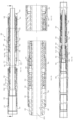
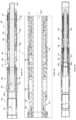
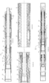
- a locator 300 is provided.
- the locator 300 includes a conveyance member 301.
- the conveyance member 301 includes a mandrel 301A.
- the conveyance member 301 is configured for coupling to a workstring 220.
- the workstring 220 is deployable within a wellbore 102 that extends into a subterranean formation 100.
- the conveyance member 301 is translatable with the workstring 220 and is, therefore, moveable through the wellbore 102 in response to a force being applied to the workstring 220.
- the locator 300 is moveable through the wellbore 102 in response to a force being applied to the workstring 220.
- the locator 300 includes a wellbore coupler 302.
- the wellbore coupler 302 includes an engagement member 306, and the engagement member 306 includes a protuberance, such as a locator block 306A.
- the engagement member 306 is provided for becoming releasably retained (such as, for example, via the locator block 306A) by a wellbore feature 202 (such as, for example, a locate profile 202 defined within a wellbore string, such as, for example, casing string) within a wellbore 102.
- the releasable retention is such that relative displacement between the locator 300 and the locate profile 202 (or other wellbore feature), such as along an axis that is parallel, or substantially parallel, to the central longitudinal axis of the wellbore 102, is at least impeded.
- the engagement member 306 extends outwardly relative to the central longitudinal axis of the conveyance member 301.
- the locator block 306A is sufficiently large such that inadvertent locating of the locator block 306A within a recess of the wellbore 102 (such as a recess within the wellbore string 200, for example, a casing string), other than the locate profile 202, is avoided.
- the engagement member 306 is biased towards a locating position, and is displaceable, relative to the mandrel 308, between the locating position and a retracted position. While releasably retained by the locate profile 202, the engagement member 306 is disposed in the locating position. After having become released from retention by the locate profile 202, the engagement member 306 is disposed in the retracted position.
- the displaceability of the engagement member 306 from the retracted position to the locating position is outwardly relative to the central longitudinal axis of the wellbore 102, or the central longitudinal axis of the conveyance member 301, or both, and the displaceability of the engagement member 306 from the locating position to the retracted position is inwardly relative to the central longitudinal axis of the wellbore 102, or the central longitudinal axis 301B of the conveyance member 301, or both.
- the wellbore coupler 302 includes one or more resilient members that exert a biasing force for effecting the biasing of the locator block 306A to the locating position.
- the resilient members 304 are in the form of collet springs (for example, beam springs), that are separated by slots.
- the collet springs 304 may be referred to as collet fingers.
- a locator block 306A is disposed on one or more of the collet springs 304.
- the locator block 306A is defined as a protuberance extending from the collet spring 304.
- the collet springs 304 are configured for a limited amount of compression in response to a compressive force applied inwardly relative to a longitudinal axis of the mandrel. Because of their resiliency, the collet springs 304 are able to pass by a restriction in a wellbore 102 while returning to its original shape.
- the collet springs 304 expand such that the locator block 306A is displaced outwardly relative to the central longitudinal axis of wellbore 102, towards the locate profile 202, for disposition in the locating position such that the locator block 306A becomes releasably retained by the locate profile 202.
- the locate profile 202 is shaped (for example, tapered inwardly towards the central longitudinal axis of the wellbore 102, such as, for example, at its uphole end) so as to encourage the displacement of the locator block 306A from the locate profile 202 (i.e. displacement of the engagement member 306 from the locating position to the retracted position).
- the locate profile 202 is tapered, at its uphole end, at an angle of between 40 degrees and 90 degrees relative to the longitudinal axis of the wellbore 102.
- the locate profile 202 is tapered at its downhole end at an angle of between 5 degrees and 90 degrees relative to the longitudinal axis of the wellbore 102.
- the force required to release the engagement member 306 from retention by the locate profile 302 is relatively less while the locator 300 is being run-in-hole than while the locator 300 is being pulled up-hole.
- the locate profile 202 does not significantly impede the running-in-hole of the locator 300, while being available to releasably retain the engagement member 306 as the locator 300 is being pulled-out-of hole and contribute to withstanding such release until a sufficient force, that is noticeable at the surface, is applied to the engagement member 306.
- the locator 300 includes a displacement hindering member 316 for preventing the displacement of the engagement member 306.
- the displacement hindering member 316 is configured for preventing (such as, for example, blocking) the displacement of the engagement member 306 from the locating position (such as, for example, while the engagement member 306 disposed within a locate profile 202, such as, for example, while the engagement member 306 is being releasably retained by the locate profile 202) to the retracted position (such as, for example, while the engagement member 306 is released from retention by the locate profile 202).
- the preventing of the displacement includes opposing of the displacement. In some embodiments, the preventing of the displacement is being effected while the engagement member 306 is disposed in the locating position. In some embodiments, for example, the preventing of the displacement is being effected while the engagement member 306 is supported by the displacement hindering member 316. In some embodiments, for example, the preventing of the displacement is being effected while the wellbore coupler 302 is engaged to the displacement hindering member 316. In some embodiments, for example, the wellbore coupler 302 is seated on the displacement hindering member 316 while the wellbore coupler 302 is engaged to the displacement hindering member.
- At least one of the engagement member 306 and the displacement hindering member 316 is displaceable relative to the other one of the engagement member 306 and the displacement hindering member 316, while the displacement of the engagement member 306 to the retracted position is being prevented, for effecting a change in condition of the engagement member 306 such that the engagement member 306 becomes displaceable to the retracted position.
- the displacement hindering member 316 is displaceable relative to the engagement member 306, while the displacement of the engagement member 306 to the retracted position is being prevented, for effecting a change in condition of the engagement member 306 such that the engagement member 306 becomes displaceable to the retracted position.
- the engagement member is displaceable relative to the displacement hindering member 316, while the displacement of the engagement member 306 to the retracted position is being prevented, for effecting a change in condition of the engagement member 306 such that the engagement member 306 becomes displaceable to the retracted position.
- the displacement hindering member 316 is displaceable relative to the engagement member 306, and engagement member is displaceable relative to the displacement hindering member 316, while the displacement of the engagement member 306 to the retracted position is being prevented, for effecting a change in condition of the engagement member 306 such that the engagement member 306 becomes displaceable to the retracted position.
- the effecting a change in condition of the engagement member 306 includes defeating the preventing of the displacement.
- the effecting a change in condition of the engagement member 306 includes effecting positioning of the engagement member 306 relative to the displacement hindering member 316 such that there is an absence, or substantial absence, of interference to the displacement of the engagement member 306, by the displacement hindering member 316, to the retracted position.
- the effecting a change in condition of the engagement member 306 includes effecting positioning of the engagement member 306 relative to the displacement hindering member 316 such that there is an absence, or substantial absence, of opposition to the displacement of the engagement member 306, by the displacement hindering member 316, to the retracted position.
- the effecting a change in condition of the engagement member 306 includes effecting positioning of the engagement member 306 relative to the displacement hindering member 316 such that there is an absence, or substantial absence, of supporting of the engagement member 306 by the displacement hindering member 316. In some embodiments, for example, the effecting a change in condition of the engagement member 306 includes effecting positioning of the engagement member 316 relative to the displacement hindering member 306 such that there is an absence, or substantial absence, of engagement of the engagement member 306 by the displacement hindering member 316.
- the preventing displacement is being effected while the engagement member 306 is seated on the displacement hindering member 316; and the effecting a change in condition of the engagement member 306 such that the engagement member 306 becomes displaceable to the retracted position, for which the engagement member 306 and the displacement hindering member 316 are displaceable relative to one another while the displacement of the engagement member 306 to the retracted position is being prevented, includes effecting the unseating of the engagement member 306 relative to the displacement hindering member 316.
- the displaceability of at least one of the engagement member 306 and the displacement hindering member 316, relative to the other one of the engagement member 306 and the displacement hindering member 316, while the displacement of the engagement member 306 to the retracted position is being prevented, for effecting a change in condition of the engagement member 306 such that the engagement member 306 becomes displaceable to the retracted position is effected by displaceability of the at least one of the engagement member 306 and the displacement hindering member 316 relative to the other one of the engagement member 306 and the displacement hindering member 316 along an axis that is transverse (such as, for example, orthogonal or substantially orthogonal) to the axis 3024 along which the engagement member 306 is displaceable between the locating and retracted positions.
- the displaceability of the at least one of the engagement member 306 and the displacement hindering member 316 relative to the other one of the engagement member 306 and the displacement hindering member 316 is along an axis that is parallel, or substantially parallel, to the central longitudinal axis 301B of the conveyance member 301.
- the displaceability, of at least one of the engagement member 306 and the displacement hindering member 316, relative to the other one of the engagement member 306 and the displacement hindering member 316, while the displacement of the engagement member 306 to the retracted position is being prevented, for effecting a change in condition of the engagement member 306 such that the engagement member 306 becomes displaceable to the retracted position, is effected by displaceability of the displacement hindering member 316 relative to the engagement member 306.
- the displacement hindering member 316 is displaceable relative to the engagement member 306, while the displacement of the engagement member 306 to the retracted position is being prevented, for effecting a change in condition of the engagement member 306 such that the engagement member 306 becomes displaceable to the retracted position.
- the displaceability of the displacement hindering member 316 relative to the engagement member 306 is along an axis that is transverse to the axis 3024 along which the engagement member 306 is displaceable between the locating and retracted positions.
- the displaceability of the displacement hindering member 316 relative to the engagement member 306 is along an axis that is orthogonal, or substantially orthogonal, to the axis 3024 along which the engagement member 306 is displaceable between the locating and retracted positions.
- the displaceability of the displacement hindering member 316, relative to the engagement member is along an axis that is parallel, or substantially parallel, to the central longitudinal axis 301 of the conveyance member 301.
- the engagement member 306 is non-displaceable, or substantially non-displaceable, relative to the axis along which the engagement member 306 is displaceable between the locating and retracted positions.
- the locator 300 includes a displacement hindering member 316 for impeding the displacement of the engagement member 306.
- the displacement hindering member 316 is configured for impeding the displacement of the engagement member 306 from the locating position (such as, for example, while the engagement member 306 disposed within a locate profile 202, such as, for example, while the engagement member 306 is being releasably retained by the locate profile 202) to the retracted position (such as, for example, while the engagement member 306 is released from retention by the locate profile 202).
- the impeding of the displacement includes opposing of the displacement.
- the impeding of the displacement is being effected while the engagement member 306 is disposed in the locating position.
- the impeding of the displacement is being effected while the engagement member 306 is supported by the displacement hindering member 316.
- the impeding of the displacement is being effected while the wellbore coupler 302 is engaged to the displacement hindering member 316.
- the wellbore coupler 302 is seated on the displacement hindering member 316 while the wellbore coupler 302 is engaged to the displacement hindering member.
- At least one of the engagement member 306 and the displacement hindering member 316 is displaceable relative to the other one of the engagement member 306 and the displacement hindering member 316, while the displacement of the engagement member 306 to the retracted position is being impeded, for effecting a change in condition of the engagement member 306 such that the engagement member 306 becomes displaceable to the retracted position.
- the displacement hindering member 316 is displaceable relative to the engagement member 306, while the displacement of the engagement member 306 to the retracted position is being impeded, for effecting a change in condition of the engagement member 306 such that the engagement member 306 becomes displaceable to the retracted position.
- the engagement member is displaceable relative to the displacement hindering member 316, while the displacement of the engagement member 306 to the retracted position is being impeded, for effecting a change in condition of the engagement member 306 such that the engagement member 306 becomes displaceable to the retracted position.
- the displacement hindering member 316 is displaceable relative to the engagement member 306, and the engagement member 306 is displaceable relative to the displacement hindering member 316, while the displacement of the engagement member 306 to the retracted position is being impeded, for effecting a change in condition of the engagement member 306 such that the engagement member 306 becomes displaceable to the retracted position.
- the effecting a change in condition of the engagement member 306 includes defeating the impeding of the displacement.
- the effecting a change in condition of the engagement member 306 includes effecting positioning of the engagement member 306 relative to the displacement hindering member 316 such that there is an absence, or substantial absence, of interference to the displacement of the engagement member 306, by the displacement hindering member 316, to the retracted position.
- the effecting a change in condition of the engagement member 306 includes effecting positioning of the engagement member 306 relative to the displacement hindering member 316 such that there is an absence, or substantial absence, of opposition to the displacement of the engagement member 306, by the displacement hindering member 316, to the retracted position.
- the effecting a change in condition of the engagement member 306 includes effecting positioning of the engagement member 306 relative to the displacement hindering member 316 such that there is an absence, or substantial absence, of supporting of the engagement member 306 by the displacement hindering member 316. In some embodiments, for example, the effecting a change in condition of the engagement member 306 includes effecting positioning of the engagement member 316 relative to the displacement hindering member 306 such that there is an absence, or substantial absence, of engagement of the engagement member 306 by the displacement hindering member 316.
- the impeding displacement is being effected while the engagement member 306 is seated on the displacement hindering member 316; and the effecting a change in condition of the engagement member 306 such that the engagement member 306 becomes displaceable to the retracted position, for which the engagement member 306 and the displacement hindering member 316 are displaceable relative to one another while the displacement of the engagement member 306 to the retracted position is being impeded, includes effecting the unseating of the engagement member 306 relative to the displacement hindering member 316.
- the displaceability of at least one of the engagement member 306 and the displacement hindering member 316, relative to the other one of the engagement member 306 and the displacement hindering member 316, while the displacement of the engagement member 306 to the retracted position is being impeded, for effecting a change in condition of the engagement member 306 such that the engagement member 306 becomes displaceable to the retracted position is effected by displaceability of the at least one of the engagement member 306 and the displacement hindering member 316 relative to the other one of the engagement member 306 and the displacement hindering member 316 along an axis that is transverse (such as, for example, orthogonal or substantially orthogonal) to the axis 3024 along which the engagement member 306 is displaceable between the locating and retracted positions.
- the displaceability of the at least one of the engagement member 306 and the displacement hindering member 316 relative to the other one of the engagement member 306 and the displacement hindering member 316 is along an axis that is parallel, or substantially parallel, to the central longitudinal axis 301 of the conveyance member 301.
- the displaceability, of at least one of the engagement member 306 and the displacement hindering member 316, relative to the other one of the engagement member 306 and the displacement hindering member 316, while the displacement of the engagement member 306 to the retracted position is being impeded, for effecting a change in condition of the engagement member 306 such that the engagement member 306 becomes displaceable to the retracted position, is effected by displaceability of the displacement hindering member 316 relative to the engagement member 306.
- the displacement hindering member 316 is displaceable relative to the engagement member 306, while the displacement of the engagement member 306 to the retracted position is being impeded, for effecting a change in condition of the engagement member 306 such that the engagement member 306 becomes displaceable to the retracted position.
- the displaceability of the displacement hindering member 316 relative to the engagement member 306 is along an axis that is transverse to the axis along which the engagement member 306 is displaceable between the locating and retracted positions.
- the displaceability of the displacement hindering member 316 relative to the engagement member 306 is along an axis that is orthogonal, or substantially orthogonal, to the axis along which the engagement member 306 is displaceable between the locating and retracted positions.
- the displaceability of the displacement hindering member 316, relative to the engagement member is along an axis that is parallel, or substantially parallel, to the central longitudinal axis of the conveyance member 301.
- the engagement member 306 is non-displaceable, or substantially non-displaceable, relative to the axis along which the engagement member 306 is displaceable between the locating and retracted positions.
- the displaceability of the engagement member 306, between the locating and retracted positions is along an axis that is transverse to the central longitudinal axis of the conveyance member 301. In some embodiments, for example, the displaceability of the engagement member 306, between the locating to the retracted position, is along an axis 3024 that is orthogonal, or substantially orthogonal, to the central longitudinal axis 301 of the conveyance member 301.
- the displaceability of the engagement member 306, from the locating to the retracted position is inwardly towards the central longitudinal axis 301 of the conveyance member, and the displaceability of the engagement member 306, from the locating to the retracted position, is outwardly relative the central longitudinal axis of the conveyance member.
- the engagement member 306 is non-displaceable, or substantially non-displaceable, relative to the axis 3024 along which the engagement member 306 is displaceable between the locating and retracted positions.
- the preventing or impeding of the displacement of the displacement hindering member 316, relative to the engagement member 306, is effected mechanically.
- the wellbore coupler 302 is slidably mounted over the conveyance member 301.
- the conveyance member 301 includes wellbore coupler retainer members 310A, 310B (such as, for example, in the form of collars 310A, 310B) for engaging the wellbore coupler 302, and thereby limiting displacement of the wellbore coupler 302 relative to the conveyance member 301.
- the wellbore coupler retainer member 310A transmits an uphole pulling force, being applied to the conveyance member 301, from the conveyance member 301 to the wellbore coupler 302.
- the wellbore coupler retainer member 310A is defined by a terminal end 320A of the housing 320.
- the transmission of such an uphole pulling force effects displacement of the wellbore coupler 302 along an axis that is parallel, or substantially parallel, to the central longitudinal axis of the wellbore 102, along an axis that is parallel, or substantially parallel, to the central longitudinal axis of the conveyance member 301, or both.
- urging of the release of the engagement member 306 from the retention by the locate profile 202, that is being prevented or impeded by the displacement hindering member 316 is effected, while: (i) the engagement member 306 is releasably retained by the locate profile 202 and the wellbore coupler 302 is shouldered versus the wellbore coupler retainer member 310A, and (ii) the wellbore coupler retainer member 310A is transmitting an uphole pulling force (being applied to the conveyance member 301, such as via the workstring 220) from the conveyance member 301 to the wellbore coupler 302.
- the displacement of the engagement member 306 from the locating position to the retracted position is effected in response to urging by the conveyance member 301.
- the wellbore coupler retainer member 310B is also provided and limits uphole displacement of the wellbore coupler 302, relative to the conveyance member 301, while the locator 300 is being run-in-hole with the workstring 220 through the wellbore 102.
- the wellbore coupler 302 slidably engages the wellbore string 200 in a compressed condition, and is subjected to frictional drag forces exerted by the wellbore string 200, resulting in the wellbore coupler 302 being urged uphole, relative to the mandrel 308, by the frictional drag forces.
- the wellbore coupler retainer 310B limits uphole displacement of the wellbore coupler 302, relative to the conveyance member 301, that is being urged by these frictional drag forces, thereby rendering the wellbore coupler 302 translatable with the conveyance member 301 in a downhole direction by virtue of the urging of the displacement of the wellbore coupler 302, in a downhole direction, by the wellbore coupler retainer member 310B.
- the wellbore coupler retainer member 310B is defined by a shoulder formed in the conveyance member 301.
- the displacement of the engagement member 306 from the locating position to the retracted position is along a displacement axis 3024.
- the displacement of the engagement member 306 to the retracted position is prevented or impeded by the displacement hindering member 316.
- the preventing or impeding of the displacement is effected while the engagement member 306 is supported on, engaged to, or both supported on and engaged to, an engagement surface 3162 of the displacement hindering member 316.
- the normal axis 3164 of the engagement surface 3162 of the displacement hindering member 316 is disposed at an acute angle relative to the displacement axis 3024.
- the acute angle is between 10 degrees and 65 degrees.
- the acute angle is between 45 degrees and 60 degrees, such as about 53 degrees.
- the acute angle is between 15 degrees and 25 degrees, such as about 20 degrees.
- the normal axis of the engagement surface 3162 of the displacement hindering member 316 is disposed at an acute angle relative to a central longitudinal axis 3021 of the conveyance member 301.
- the acute angle is between 25 degrees and 80 degrees.
- the acute angle is between 30 degrees and 45 degrees, such as about 38 degrees.
- the acute angle is between 65 degrees and 80 degrees, such as about 70 degrees.
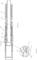
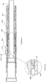
- the preventing or impeding of the displacement of the engagement member 306 from the locating position to the retracted position, by the displacement hindering member 316 is effected by engagement between an engagement surface 3022 of the wellbore coupler 302 and the engagement surface 3162 of the displacement hindering member 316 (see Figures 5A and 5B ).
- the engagement is a slidable engagement. In this respect, while disposed in the engagement with the displacement hindering member 316, the wellbore coupler 302 is displaceable, relative to the displacement hindering member 316, by slidable movement.
- the engagement surface 3162 of the displacement hindering member 316 across which the engagement surface 3022 of the wellbore coupler 302 is configured to slidably traverse, while the displacement of the displacement hindering member 316, relative to the engagement member 306, is being effected for enabling the displacement of the engagement member 306 to the retracted position, has a surface area of at least 0.06 square inches.
- the engagement member 306 and the displacement hindering member 316 are co-operatively configured such that the engagement member 306 is slidably engaged to the engagement surface 3162 of the displacement hindering member 316, while the displacement of the engagement member 306 to the retracted position is being urged and the displacement hindering member 316 is preventing or impeding the displacement of the engagement member 306 to the retracted position.
- the engagement surface 3022 of the wellbore coupler is disposed on a protuberance 3026.
- the protuberance 3026 is disposed on a side of the wellbore coupler 302 that is opposite to the side of the wellbore coupler 302 on which the engagement member 306 is disposed.
- the protuberance 3026 extends inwardly relative to the central longitudinal axis of the conveyance member 301 (or, towards the central longitudinal axis of the conveyance member 301).
- the protuberance 3026 is aligned with the locator block 306A.
- the preventing or impeding of the displacement of the engagement member 306 from the locating position to the retracted position, by the displacement hindering member 316 increases the amount of force that is applied to the engagement member 306 to urge its displacement from the locating position to the retracted position. This provides a less ambiguous indication to an operator at the surface that the engagement member 306 has becomes releasably retained by the locate profile 202.
- the displacement hindering member 316 is displaceable between a wellbore coupler-retaining position (see Figure 5A ) and a non-interference position (see Figures 6A and 7 ), and biased towards the wellbore coupler-retaining position.
- the displacement hindering member 316 In the wellbore coupler-retaining position, the displacement hindering member 316 is preventing or impeding displacement of the engagement member 306 to the retracted position.
- the non-interference position opposition, by the displacement hindering member 316, to the displacement of engagement member 306 to the released position, is absent or substantially absent.
- the term "substantially absent”, in this context, means that, while the engagement member 306 is being displaced from the locating to the retracted position, the magnitude of the force, being applied by the displacement hindering member 316 to the engagement member 306, in a direction that is parallel, or substantially parallel, to an axis along which the engagement member 306 is being displaced from the locating position to the retracted position, is less than 20% (including zero ("0")) of the magnitude of the maximum force being applied by the displacement hindering member 316 to the engagement member 306, in a direction that is parallel, or substantially parallel, to an axis along which the engagement member 306 is being displaced from the locating position to the retracted position, while: (i) the engagement member 306 is disposed in the locating position, (ii) the displacement hindering member 316 is disposed in the wellbore coupler-retaining position, and (iii) displacement of the engagement member 306 towards to the retracted position is being urged.
- the displaceability of the displacement hindering member 316, between the wellbore coupler-retaining position and the non-interference position is along an axis that is transverse (such as, for example, orthogonal or substantially orthogonal) to the normal axis of the engagement surface 3022.
- the displaceability of the displacement hindering member 316, between the wellbore coupler-retaining position and the non-interference position is along an axis that is transverse (e.g. orthogonal or substantially orthogonal) to the axis 3024 along which the engagement member 306 is displaceable between the locating and retracted positions.
- the displaceability of the displacement hindering member 316, between the wellbore coupler-retaining position and the non-interference position is along an axis that is parallel, or substantially parallel, to the central longitudinal axis of the conveyance member 301, or along an axis that is parallel, or substantially parallel, to the central longitudinal axis of the wellbore 102, or both.
- the displaceability of the displacement hindering member 316, from the wellbore coupler-retaining position to the non-interference position is in a downhole direction.
- the engagement member 306 and the displacement hindering member 316 are co-operatively configured such that:
- the urging of the displacement of the displacement hindering member 316 to the non-interference position is opposed by the biasing force that biases the displacement hindering member 316 to the wellbore coupler-retaining position.
- the urging of the displacement of the displacement hindering member 316 to the non-interference position overcomes at least the biasing force that biases the displacement hindering member 316 to the wellbore coupler-retaining position.
- the displaceability of the displacement hindering member 316 is effectible by slidable mounting of the displacement hindering member 316 over the conveyance member 301.
- the displacement hindering member 316 is displaceable, relative to the conveyance member 301, by slidable movement.
- the displacement hindering member 316 is tubular and is slidably mounted over the conveyance member 301, such that the conveyance member 301 extends through the displacement hindering member 316.
- the biasing of the displacement hindering member 316 to the wellbore coupler-retaining position is effected by a biasing member 318, such as a resilient member 318, such as a compression spring 318.
- a biasing member 318 such as a resilient member 318, such as a compression spring 318.
- the biasing member 318 is disposed within a housing 320 that is mounted to the mandrel 301A.
- the biasing member 318 is in the form of a compression spring characterized by a greater spring force (and, in some embodiments, is characterized by a larger radius) relative to the compression spring illustrated in Figures 1 to 6 .
- the compression spring in Figures 7 to 9 is characterized by a spring force of between 2,000 to 2,500 pounds, whereas the compression spring in Figures 1 to 6 is characterized by a spring force of about 500 pounds.
- a compression spring, with a larger spring force may be suitable in those embodiments where the normal axis 3164 of the engagement surface 3162 of the displacement hindering member 316 is disposed at relatively greater angles of inclination relative to the displacement axis 3024.
- the displacement hindering member 316 In response to the urging of the displacement of the displacement hindering member 316 to the non-interference position by the engagement member 306, while the displacement of the engagement member 306 to the retracted position is being urged and the displacement hindering member 316 is preventing or impeding the displacement of the engagement member 306 towards the retracted position, the displacement hindering member is displaced towards the non-interference position with effect that the resilient member 118 absorbs energy and becomes compressed.
- the displacement hindering member 316 includes a wellbore coupler-engagement portion 3161 that includes the engagement surface 3162, and also includes a shearable portion 3163 interposed between the wellbore coupler engagement portion 3161 and the biasing member 318, and coupled to the portion 3161 with a shear pin 3165.
- the compressibility of the resilient member 318 may become compromised due to solids ingress, preventing, or impeding, displacement of the displacement hindering member 316 for enabling releasing of the engagement member 306 from retention by the locate profile 202.
- the shear pin 3165 is configured to fracture to enable independent movement of the portion 3161 relative to the portion 3163.
- the displacement hindering member 316 further includes a force transmission member 314 including a pusher 3167 (such as a piston 3167) that is coupled to the biasing member 318, and interposed between the shearable portion 3163 and the biasing member 318, while being in contact engagement with the portion 3163.
- a pusher 3167 such as a piston 3167
- the piston 3167 is absent.
- having a separate piston 3167 provides flexibility in re-configuring the locator to incorporate a different mechanism for promoting reliable locating.
- the housing 320 is not provided, (such as, for example, the embodiment illustrated in Figures 7 to 9 ).
- the biasing member 318 is retained between a resilient member retainer 321 and the collar 310A.
- the collar 310A includes a plurality of spaced-apart tabs 310AA each one of the tabs 310AA extending outwardly (e.g. radially) relative to a central longitudinal axis of the mandrel.
- the piston 3167 includes a base 3167A and a plurality of fingers 3167B extending longitudinally from the base 3167A and through the spaces between the tabs 310AA.
- the base 3167A is coupled to the resilient member 318.
- the fingers 3167B are for effecting contact engagement with the shearable portion 3163 of the displacement hindering member 3161, and thereby effecting force transmission between the shearable portion 3163 and the biasing member 318.
- the piston 3167 is movable relative to the collar 310A to facilitate displacement of the displacement hindering member 316 from the wellbore coupler-retaining position to the non-interference position, such as that being urged by the engagement member 306 while an uphole pulling force is being applied to the wellbore coupler 302 via the collar 310A.
- the collar 310A also functions as a retainer for opposing displacement of the piston 3167 in a direction opposite to the direction in which the displacement hindering member 316 is displaced while being displaced from the wellbore coupler-retaining position to the non-interference position.
- the displacement hindering member 316 is maintained spaced-apart from the engagement member 306 such that the displacement hindering member 316 does not interfere with displacement of the engagement member 306 between the locating and the retracted positions.
- the engagement member 306 traverses one or more locate profiles 302 within the wellbore 102, and it is desirable to provide conditions such that the force required to conduct the locator 300 (and, therefore, the engagement member 306) past the locate profiles 302 is minimized.
- the displacement hindering member 316 and the engagement member 306 are co-operatively configured such that, while the locator 300 is being run-in-hole into the wellbore 102, the displacement hindering member 316 is disposed relative to the engagement member 306 such that interference, by the displacement hindering member 316, to the displacement of the engagement member 306 between the locating and retracted positions is absent or substantially absent.
- the displacement hindering member 316 is spaced apart relative to the engagement member 306
- the conveyance member 301 includes a displacement hindering member retainer 3082 for limiting uphole displacement of the displacement hindering member 316 relative to the conveyance member 301 (which, in some embodiments, is being urged by frictional drag forces exerted by the wellbore string) such that while the locator 300 is being run-in-hole into the wellbore 102, the displacement hindering member 316 is disposed relative to the engagement member 306 such that interference, by the displacement hindering member 316, to the displacement of the engagement member 306 between the locating and the retracted positions, is absent or substantially absent (and, in some embodiments, for example, the engagement member 306 is maintained in a spaced apart relationship relative to the displacement hindering member 316).
- the locating of the locator 300 is effected while the locator is being pulled-out-of-hole.
- the locator 300 is conducted uphole in response to displacement of the conveyance member 301 in the uphole direction.
- the pulling up force applied to the conveyance member 301 via the workstring 220 is transmitted to the wellbore coupler 302 via a force transmission surface 3167 of the displacement hindering member 316 (see Figure 2B ).
- the normal axis of the force transmission surface 3167 is disposed parallel, or substantially parallel, to a central longitudinal axis of the conveyance member 301.
- the locator 300 has been run-in-hole to a desired location within the wellbore 102 (for example, estimated based on the length of workstring 220 that has been deployed downhole)
- a pulling up force is exerted on the workstring 220, causing the conveyance member 301 to be pulled up hole.
- the pulling up force is transmitted to the displacement hindering member 316 via the resilient member 318, and consequently to the wellbore coupler 302 (more specifically, the protuberance 3026), resulting in uphole displacement of the engagement member 306.
- the engagement member 306 is spaced apart from the collar 310A of the mandrel 308.
- the locator 300 is run-in-hole with the workstring 220. While the locator 300 is being run-in-hole into the wellbore 102, the wellbore coupler 302 slidably engages the wellbore string 200 in a compressed condition, and is subjected to frictional drag forces exerted by the wellbore string 200, resulting in the wellbore coupler 302 being urged uphole, relative to the mandrel 308, by the frictional drag forces.
- the wellbore coupler retainer 310B limits uphole displacement of the wellbore coupler 302, relative to the conveyance member 301, that is being urged by these frictional drag forces, thereby rendering the wellbore coupler 302 translatable with the conveyance member 301 in a downhole direction by virtue of the urging of the displacement of the wellbore coupler 302, in a downhole direction, by the wellbore coupler retainer member 310B.
- the engagement member 306 is maintained in a spaced apart relationship relative to the displacement hindering member 316 by the displacement hindering member retainer 3082.
- the workstring 220 Upon moving past the general area where locating is intended, the workstring 220 reverses direction and is then pulled uphole, along with the conveyance member 301.
- the displacement hindering member 316 By virtue of its engagement with the pusher 3167, the displacement hindering member 316, likewise, is pulled uphole.
- the wellbore coupler 302 (including the engagement member 306) is also pulled uphole.
- the collet springs 304 expand such that the engagement member 306 becomes disposed within the locate profile 202. In this configuration, the engagement member 306 is disposed in the locating position.
- locator block 306A and the locate profile 202, (ii) the spring force of the wellbore coupler 302, (iii) the force resisting relative movement between the engagement member 306 and the displacement hindering member 316, and (iv) the force being applied by the resilient member 318.
- this stepwise reduction is attributable to the fact that, instead of being required to overcome the frictional force opposing the movement of the engagement surface 3022 of the protuberance 3026 relative to the engagement surface 3162 of the displacement hindering member 316, the normal axis of which is disposed at an angle relative to axis of displacement along which the protuberance 3026 is being displaced towards the retracted position, the uphole pulling force is required to only overcome the frictional force opposing the movement of the engagement surface 3022 of the protuberance 3026 relative to a surface 3168 of the displacement hindering member 316 that is disposed parallel to, or substantially parallel to, the axis of displacement along which the protuberance 3026 is being displaced towards the released position, which is of a much smaller magnitude.
- the locator may be conducted uphole to effect locating with the next uphole locate profile 202, by pulling up on the workstring 220.
- the first pusher 330 by virtue of its engagement to the displacement hindering member 316, urges the displacement of the displacement hindering member 316 in concert with the workstring 220.
- the wellbore coupler 302 is also pulled uphole.
- the engagement member 306 becomes displaced, being urged by the bias of the collet springs 304.
- the impeding of the displacement of the displacement hindering member 316, relative to the engagement member 306, by fluid flow resistance, and thereby delaying the release of the engagement member 306 from retention by the locate profile, by opposition to fluid flow urged by such displacement is effected.
- the impeding of the displacement provides more time for an operator at the surface to observe an indication that the engagement member 306 has become releasably retained by the locate profile 202 (e.g. an increase in force required to displace the engagement member 306 from the locate profile 202).
- the locator further includes fluid 332, and the fluid 332 is disposed within the fluid conductor 334 for being displaced through the fluid conductor 334 by a reaction force that is responsive to a displacement-urging force that is urging the displacement of the displacement hindering member 316, relative to the engagement member 306, while the displacement of the engagement member 306 to the retracted position is being prevented or impeded, for effecting the change in condition of the engagement member 306 such that the engagement member 306 becomes displaceable (for example, relative to the locate profile 202) to the retracted position.
- the displacement of the fluid 332 includes conduction of the fluid 332 through the fluid conductor 334 for effecting the impeding of the displacement of the displacement hindering member 316 relative to the engagement member 306 while such displacement is being urged.
- the impeding of the displacement is attributable to resistance to fluid flow that is imparted by the fluid conductor 334 while the fluid 332 is being conducted through the fluid conductor 334.
- the fluid conductor 334 includes a flow restrictor 336.
- the fluid conductor 334 includes a valve member 338 disposed in fluid communication with the fluid 332 and configured for opening in response to pressure of the fluid 332 exceeding a predetermined minimum pressure, wherein the fluid 332 is disposed in force transmission communication with the engagement member 306 such that the force urging the displacement of the displacement hindering member 316 relative to the engagement member 306 (for effecting the change in condition of the engagement member 306, such as, for example, the unseating of the protuberance 3026) is transmitted to the fluid 332 to effect an increase in pressure of the fluid 332, wherein the exceeding of a predetermined minimum pressure corresponds to the application of a force that is at or above the predetermined minimum force.
- the valve member 338 functions as a pressure relief device.
- the engagement member 306, the fluid conductor 334, the fluid 332 and the displacement hindering member 316 are co-operatively configured such that:
- the workstring 220 is pulled uphole so as to effect locating within another region of the wellbore 102, further uphole from the earlier locate.
- the engagement member 306 In order for the engagement member 306 to become releasably retained by an uphole locate profile 202, while introducing a delay to its release from such releasable retention from the locate profile 202, the engagement member 306 is displaceable relative to the displacement hindering member 316, while the engagement member 306 is displaceable between the locating and retracted positions, by a return device 340, with effect that the engagement member and the displacement hindering member become co-operatively disposed such that the displacement of the engagement member to the retracted position is prevented or impeded.
- the functionality of re-seating the engagement member 306 on the displacement hindering member 316, for preventing, or impeding, the release of the engagement member 306 from retention by another locate profile 202 is combined with the functionality of impeding the displacement of the displacement hindering member 316, relative to the engagement member 306, for effecting the change in condition of the engagement member 316 (such that the engagement member becomes displaceable to the retracted position), so that there is sufficient time for a positive indication of the locating of the wellbore coupler 302, effected by the preventing, or impeding, to be detected uphole.
- the locator 300 includes a force transmitter 314.
- the force transmitter 314 urges translation of the wellbore coupler 302 with the conveyance member 301, during uphole displacement of the conveyance member 301 through the wellbore 102.
- the force transmitter 314 also urges displacement of the wellbore coupler 302, relative to the displacement hindering member 316, for effecting seating (including re-seating) of the engagement member 306 on the displacement hindering member 316.
- the force transmitter 314 includes a first pusher 330, a second pusher 342, and the fluid 332.
- the force transmitter 314 is disposed within a housing 344 that is mounted to the conveyance member 301.
- the force transmitter 314 is biased by a biasing member 341 for urging, via the force transmitter 314, the displacement of the engagement member 306 relative to the displacement hindering member 316 (such as, for example, in the uphole direction, and, in some embodiments, along an axis that is parallel to the central longitudinal axis of the conveyance member 301, or along an axis that is parallel to the central longitudinal axis of the wellbore, or both), while the engagement member 306 is displaceable between the locating and retracted positions (i.e.
- the displacement hindering member and the engagement member are co-operatively disposed such that there is an absence, or substantial absence, of the preventing, or impeding, of the displacement of the engagement member 306 to the retracted position), with effect that the engagement member 306 and the displacement hindering member 316 become co-operatively disposed such that the displacement of the engagement member 306 to the retracted position is prevented or impeded.
- the biasing member 341 is retained by a biasing member retainer 348 defined within the housing 344.
- the biasing member 341 is resilient. In some embodiments, for example, the biasing member includes a spring.
- the reaction force overcomes at least the biasing force of the biasing member 341.
- the fluid conductor 334 includes a first compartment 346 and a second compartment 350, and also includes one or more displacement-impeding fluid passages and a return fluid passage 352.
- One or more displacement-impeding fluid passages are provided for conducting the fluid 332 while the fluid 332 is being displaced from the second compartment 350 to the first compartment 346.
- the one or more displacement-impeding fluid passages includes a first displacement-impeding fluid passage 354.
- the first displacement-impeding fluid passage 354 includes a valve member 338 configured for opening in response to pressure of the fluid 332 exceeding a predetermined minimum pressure, wherein the fluid 332 is disposed in force transmission communication with the engagement member 306 such that the force urging the displacement of the displacement hindering member 316 relative to the engagement member 306 (for effecting the change in condition of the engagement member 306 such that the engagement member 306 becomes displaceable to the retracted position.) is transmitted to the fluid 332 to effect an increase in pressure of the fluid 332, wherein the exceeding of a predetermined minimum pressure corresponds to the application of a force that is at or above the predetermined minimum force.
- the one or more displacement-impeding fluid passages includes a second displacement-impeding fluid passage 356.
- the second displacement-impeding fluid passage 356 also includes a flow restrictor 336, such as, for example, an orifice.
- the second displacement-impeding fluid passage 356 is configured for conducting the fluid 332 while the fluid 332 is being displaced from the second compartment 350 to the first compartment 346, and also while the fluid 332 is being displaced from the second compartment 350 to the first compartment 346.
- the second displacement-impeding fluid passage 356 is co-operatively configured with a return fluid passage 352, for effecting the impeding of the displacement of the displacement hindering member 316 relative to the engagement member 306 during the effecting of a change in condition of the engagement member 306 such that the engagement member 306 becomes displaceable to the retracted position.
- the second displacement-impeding fluid passage 356 is additional to the first displacement-impeding fluid passage 354.
- the locator 300 includes only one of the first and second displacement-impeding fluid passages 354, 356.
- the first displacement-impeding fluid passage 354 is provided, to complement the second displacement-impeding fluid passage 356, by providing a means for more rapidly depressurizing the first compartment 332 when the force being applied by the first pusher to the wellbore coupler 302, for urging retraction of the engagement member 306 from the locate profile 202, is excessive, and may result in premature retraction even while the displacement is being prevented, or impeded, by the displacement hindering member 316, unless the fluid within the first compartment 332 is bled to the second compartment 350 at a faster rate than permitted via the second displacement-impeding fluid passage 356.
- the second displacement-impeding fluid passage 356 is independently useful in those cases where the pulling up force is relatively weak (such as when locating at relatively significant distances from the surface) and would not be sufficient to trigger opening of the valve member 338 within the first displacement-impeding fluid passage 354.
- the return fluid passage 352 is provided for conducting the fluid 332 while the fluid 332 is being displaced from the first compartment 346 to the second compartment 350.
- the return fluid passage includes a one-way valve 358 for preventing, or substantially preventing, conduction of the fluid 332 from the second compartment 350 to the first compartment 346 via the return fluid passage 352.
- the return fluid passage 352 is not functional for conducting fluid being displaced from the second compartment 350 to the first compartment 346, which would otherwise detract from the impeding of such fluid conduction that is imparted by the one or more displacement-impeding fluid passages while the displacement of the engagement member 306, relative to the displacement hindering member 316, is being effected to effect the change in condition of the engagement member 306 such that the engagement member 306 becomes displaceable to the retracted position.
- the resistance to fluid flow that the second displacement-impeding fluid passage 356 is configured to provide while conducting the fluid from the first compartment 346 to the second compartment 350, is greater than the resistance to fluid flow, that the return fluid passage 352 is configured to provide while conducting the fluid from the first compartment 346 to the second compartment 350, such as, for example, by a multiple of at least 1.1, such as, for example, by a multiple of at least 2.
- the minimum cross-sectional flow area of the return fluid passage 352 is greater than the minimum cross-sectional flow area of the second displacement-impeding passage 356, such as, for example, by a multiple of at least 1.1, such as, for example, by a multiple of at least 2.
- the resistance to fluid flow that the return fluid passage 352 is to provide is, in some embodiments, for example, less than that of the second displacement-impeding fluid passage 356.
- the rate at which fluid is being conducted from the second compartment 350 to the first compartment 346 may be insufficient in some embodiments for reliably effecting displacement of the engagement member 306, relative to the displacement hindering member 316, for effecting the co-operative disposition of the engagement member 306 and the displacement hindering member 316 such that the displacement of the engagement member to the retracted position is prevented or impeded.
- the fluid 332 is disposed within the fluid conductor 334 and configured for:
- the first pusher 330 is provided for transmitting a displacement-urging force (e.g. the force being applied to the workstring while the workstring is being pulled uphole) being received by the conveyance member for urging displacement of the locator 300 (e.g. uphole through the wellbore 102, and, in some embodiments, along an axis that is parallel to the central longitudinal axis of the conveyance member 301, or along an axis that is parallel to the central longitudinal axis of the wellbore, or both).
- a displacement-urging force e.g. the force being applied to the workstring while the workstring is being pulled uphole
- the first pusher 330 is also provided for urging conduction of the fluid 332 through the fluid conductor 334 in response to the relative displacement, between the engagement member 306 and the displacement hindering member 316 (for effecting the change in condition of the engagement member 306 such that the engagement member 306 becomes displaceable to the retracted position), for effecting impeding of such relative displacement.
- the first pusher 330 is also provided for transmitting a biasing force received from the biasing member 341, via at least the second pusher 342 and the fluid 332 for effecting co-operative disposition of the displacement hindering member 316 relative to the engagement member 306 such that displacement of the engagement member 306 to the retracted position is prevented or impeded.
- the second pusher 342 is coupled (e.g. connected) to the biasing member 341 such that the biasing of the force transmitter 314 by the biasing member 341 is effected by the coupling of the second pusher 342 to the biasing member 341.
- the second pusher 342 is disposed for effecting force transmission communication between the biasing member 341 and the fluid 332.
- the fluid 332 is disposed, relative to the first and second pushers 330, 342 for effecting force transmission communication between the first and second pushers 330, 342.
- the fluid is disposed between the first and second pushers 330, 342, and, in this respect, the second pusher 342 is disposed between the fluid 332 and the biasing member 341.
- the engagement member 306, the displacement hindering member 316, the force transmitter 314, the biasing member 341, and the fluid conductor 334 are co-operatively configured such that: the first pusher 330 urges displacement of the fluid 332 within the fluid conductor 334 with effect that: (i) the relative displacement, between the engagement member 306 and the displacement hindering member 316, for effecting the change in condition of the engagement member 306 such that the engagement member 306 becomes displaceable to the retracted position, is impeded, and (ii) absorption of energy by the biasing member 341 is effected; in response to the relative displacement, between the engagement member 306 and the displacement hindering member 316, for effecting the change in condition of the engagement member 306 such that the engagement member 306 becomes displaceable to the retracted position.
- the engagement member 306, the first pusher 330, the first compartment 346, the fluid 332, the second compartment 350, the second pusher 342, the first and second displacement-impeding fluid passages 354, 356, the return fluid passage 352, and the biasing member 341 are co-operatively configured such that:
- the engagement member 306, the displacement hindering member 316, the force transmitter 314, and the biasing member 341 are also co-operatively configured such that: displacement of the displacement hindering member 316 relative to the engagement member 306 is effected for effecting co-operative disposition of the displacement hindering member 316 relative to the engagement member 306 such that displacement of the engagement member 306 to the retracted position is prevented or impeded; in response to the urging by the biasing member 341, via the force transmitter, while: (i) the engagement member 306 is engaged to the first pusher 330, (ii) the engagement member 306 is displaceable between the locating and retracted positions; and (iii) the biasing member 341 is disposed for releasing energy for effecting the urging.
- the effected displacement of the displacement hindering member 316 relative to the engagement member 306 is effected for effecting co-operative disposition of the displacement hindering member 316 relative to the engagement member 306 such that displacement of the engagement member 306 to the retracted position is prevented or impeded, is a displacement in an uphole direction.
- the effected displacement is a along an axis that is parallel to the central longitudinal axis 301B of the conveyance member 301.
- the effected displacement is a displacement is a displacement along an axis that is transverse to the axis along which the engagement member 306 is displaceable between the locating and retracted positions.
- the wellbore coupler 302, the first pusher 330, the first compartment 346, the fluid 332, the second compartment 350, the second pusher 342, the one or more displacement-impeding fluid passages 354, 356, the return fluid passage 352, and the biasing member 341 are also co-operatively configured such that:
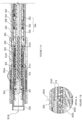
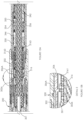
- the embodiments illustrated in Figures 11 to 16 are similar to those illustrated in Figure 1 to 10 .
- the embodiments of the locator illustrated Figures 11 to 16 are configured for effecting the impeding of the displacement of the displacement hindering member 316, relative to the engagement member 306,.
- the impeding of the displacement of the displacement hindering member 316, relative to the engagement member 306, in the embodiments of the locator illustrated in Figures 11 to 16 is additionally effected by fluid flow resistance, as described above.
- the force transmitter 314 of the locator 300 includes the first pusher 330, the second pusher 342, and the fluid 332.
- the force transmitter 314 is disposed within a housing 344 that is mounted to the conveyance member 301.
- the fluid conductor 334 is also provided for conducting the fluid 332 being displaced.
- the fluid conductor 334 includes the first compartment 346 and the second compartment 350, and also includes the first displacement-impeding fluid passage 354 and the return fluid passage 352.
- the fluid conductor 334 also includes the second displacement-impeding fluid passage 356.
- the wellbore coupler retainer 310B limits uphole displacement of the wellbore coupler 302, relative to the conveyance member 301, that is being urged by these frictional drag forces, thereby rendering the wellbore coupler 302 translatable with the conveyance member 301 in a downhole direction by virtue of the urging of the displacement of the wellbore coupler 302, in a downhole direction, by the wellbore coupler retainer member 310B.
- the engagement member 306 is maintained in a spaced apart relationship relative to the displacement hindering member 316 by the displacement hindering member retainer 3082.
- the workstring 220 Upon moving past the general area where locating is intended, the workstring 220 reverses direction and is then pulled uphole, along with the conveyance member 301.
- the displacement hindering member 316 By virtue of its engagement with the first pusher 330, the displacement hindering member 316, likewise, is pulled uphole.
- the wellbore coupler 302 (including the engagement member 306) is also pulled uphole.
- the collet springs 304 expands such that the engagement member 306 becomes disposed within the locate profile 202. In this configuration, the engagement member 306 is disposed in the locating position.
- locator block 306A and the locate profile 202, (ii) the spring force of the wellbore coupler 302, (iii) the force resisting relative movement between the engagement member 306 and the displacement hindering member 316, (iv) the force being applied by the resilient member 318, and (v) the force resulting from hydraulic pressure within the first compartment 346.
- the displacement hindering member 316 While the protuberance 3026 is slidingly downwardly, the displacement hindering member 316 is urged against the first pusher 330, effecting displacement of the fluid 332 within the fluid conductor, from the first compartment 346 to the second compartment 350, with effect that the second pusher 342 becomes displaced and urges compression of the biasing member 341.
- the relative displacement, between the engagement member 306 and the displacement hindering member 316 is impeded.
- this stepwise reduction is attributable to the fact that, instead of being required to overcome the frictional force opposing the movement of the engagement surface 3022 of the protuberance 3026 relative to the engagement surface 3162 of the displacement hindering member 316, the normal axis of which is disposed at an angle relative to axis of displacement along which the protuberance 3026 is being displaced towards the retracted position, the uphole pulling force is required to only overcome the frictional force opposing the movement of the engagement surface 3022 of the protuberance 3026 relative to a surface 3168 of the displacement hindering member 316 that is disposed parallel to, or substantially parallel to, the axis of displacement along which the protuberance 3026 is being displaced towards the released position, which is of a much smaller magnitude.
- the locator may be conducted uphole to effect locating with the next uphole locate profile 202, by pulling up on the workstring 220.
- the first pusher 330 by virtue of its engagement to the displacement hindering member 316, urges the displacement of the displacement hindering member 316 in concert with the workstring 316.
- the wellbore coupler 302 is also pulled uphole.
- the engagement member 306 becomes displaced, being urged by the bias of the collet springs 304.
- the impeding of the displacement of the engagement member 306, relative to the displacement hindering member 316, for effecting the change in condition of the engagement member 306 (in this case, the unseating of the engagement member 306) such that the engagement member 306 becomes displaceable to the retracted position is effected by fluid flow resistance, as described above.
- the impeding of the displacement of the displacement hindering member 316, relative to the engagement member 306, while the displacement of the engagement member 306 to the retracted position is being prevented, for effecting a change in condition of the engagement member 306 such that the engagement member 306 becomes displaceable to the retracted position, is effected by engagement of the wellbore coupler 302 and the first pusher 330.
- the wellbore coupler 302 is slidably mounted over the conveyance member 301.
- the conveyance member 301 includes a wellbore coupler retainer member 310 (such as, for example, in the form of a collar 310), for engaging the wellbore coupler 302.
- the wellbore coupler retainer member 310 is also provided and limits uphole displacement of the wellbore coupler 302, relative to the conveyance member 301, while the locator 300 is being run-in-hole with the workstring 220 through the wellbore 102.
- the wellbore coupler 302 slidably engages the wellbore string 200 in a compressed condition, and is subjected to frictional drag forces exerted by the wellbore string 200, resulting in the wellbore coupler 302 being urged uphole, relative to the conveyance member 301, by the frictional drag forces.
- the wellbore coupler retainer 310 limits uphole displacement of the wellbore coupler 302, relative to the conveyance member 301, that is being urged by these frictional drag forces, thereby rendering the wellbore coupler 302 translatable with the conveyance member 301 in a downhole direction by virtue of the urging of the displacement of the wellbore coupler 302, in a downhole direction, by the wellbore coupler retainer member 310.
- the wellbore coupler retainer member 310 is defined by a shoulder formed in the conveyance member 301.
- the force transmitter 314 is configured to transmit an uphole pulling force, being applied to the conveyance member 301, from the conveyance member 301 to the wellbore coupler 302.
- the displacement of the engagement member 306 from the locating position to the retracted position is along a displacement axis 3024 that is orthogonal, or substantially orthogonal, to the central longitudinal axis of the conveyance member 301, the central longitudinal axis of the wellbore 102, or both.
- the displacement hindering member 316 is configured for preventing (such as, for example, blocking) displacement of the engagement member 306 to the retracted position.
- the prevention is effected by seating of an engagement surface 3022 of the wellbore coupler 302 on the displacement hindering member 316 (see Figures 18A-C ).
- the engagement surface 3022 of the wellbore coupler 302 is disposed on a protuberance 3026.
- the protuberance 3026 is disposed on a side of the wellbore coupler 302 that is opposite to the side of the wellbore coupler 302 on which the engagement member 306 (such as another protuberance, such as, for example, the locator block 306A) is disposed.
- the protuberance 3026 extends inwardly relative to the central longitudinal axis of the conveyance member 301 (or, towards the central longitudinal axis of the conveyance member 301). In some embodiments, for example, the protuberance 3026 is aligned with the engagement member 306.
- the displacement hindering member 316 extends from the conveyance member 301 in an outwardly direction relative to the central longitudinal axis of the conveyance member 301.
- the displacement hindering member 316 is integral with the conveyance member 301. In this respect, the displacement hindering member 316 translates with the conveyance member 301.
- the displacement hindering member 316 includes a protuberance 316A that extends from the conveyance member 301 in an outwardly direction relative to the central longitudinal axis of the conveyance member 301.
- the hindering member protuberance 316A is coupled to the conveyance member 301 with a frangible coupling 316B, such as a shear pin.
- a frangible coupling 316B such as a shear pin.
- the preventing of the displacement of the engagement member 306 from the locating position to the retracted position, by the displacement hindering member 316, is effected while the engagement member 306 is disposed within the locate profile 302.
- the preventing of the displacement of the engagement member 306 from the locating position to the retracted position, by the displacement hindering member 316 is effected while the displacement hindering member 316 is disposed in alignment with the protuberance 3026, and, in some embodiments, for example, also while the displacement hindering member 316 is disposed in alignment with the locator block 306A.
- the displacement hindering member 316 is configured for displacement relative to the protuberance 3026, for effecting unseating of the engagement member 306. In some embodiments, for example, the unseating is with effect that the displacement hindering member 316 becomes displaceable to the retracted position.
- the displacement of the displacement hindering member 316, relative to the protuberance 3026, for effecting the unseating of the engagement member 306, is effectible by displacement of the displacement hindering member 316 along an axis that is transverse (such as, for example, orthogonal, or substantially orthogonal) to the normal axis of the engagement surface 3022.
- the displacement of the displacement hindering member 316, relative to the protuberance 3026, for effecting unseating of the engagement member 306, is effectible by displacement of the displacement hindering member 316 along an axis that is transverse (e.g. orthogonal or substantially orthogonal) to the axis along which the engagement member 306 is displaceable between the locating and retracted positions.
- the displacement of the displacement hindering member 316, relative to the protuberance 3026, for effecting unseating of the engagement member 306, is effectible by displacement of the displacement hindering member 316 along an axis that is parallel, or substantially parallel, to the central longitudinal axis of the conveyance member 301, or along an axis that is parallel, or substantially parallel, to the central longitudinal axis of the wellbore 102, or both.
- the locator 300 is configured such that the displacement of the displacement hindering member 316 (such as, for example, in an uphole direction), relative to the protuberance 3026, for effecting unseating of the engagement member 306, is impeded.
- the unseating of the protuberance 3026 is delayed, thereby providing more time for an operator at the surface to observe an indication that the locator block 306A has become releasably retained by the locate profile 202 (e.g. an increase in force required to displace the engagement member 306 from the locate profile 202).
- the locator 300 further includes the fluid 332.
- the fluid 332 is disposed within the fluid conductor 334 for being displaced through the fluid conductor 334 by a reaction force that is responsive to a displacement-urging force that is urging the displacement of the displacement hindering member 316, relative to the engagement member 316 (e.g. the protuberance 3026), for effecting the unseating of the engagement member 306, such that a change in condition of the engagement member 306 is effected such that the engagement member 306 becomes displaceable to the retracted position.
- the displacement of the fluid 332 includes conduction of the fluid 332 through the fluid conductor 334 for effecting the impeding of the displacement of the displacement hindering member 316 relative to the engagement member 306, while the displacement of the engagement member 306 to the retracted position is being prevented (e.g. by seating on the displacement hindering member 316), for effecting a change in condition of the engagement member 306 (e.g. the engagement member 316 becomes unseated) such that the engagement member 306 becomes displaceable to the retracted position
- the engagement member 306 is disposed in an unseated condition, and, in some of these embodiments, for example, the engagement member 306 is disposed downhole relative to the displacement hindering member 316 upon the unseating.
- the workstring 220 is pulled uphole so as to effect locating within another region of the wellbore 102, further uphole from the earlier locate.
- the engagement member 306 In order for the engagement member 306 to become releasably retained by an uphole locate profile 302, while introducing a delay to its release from such releasable retention from the locate profile 202, the engagement member 306 is displaced relative to the displacement hindering member 316, for effecting re-seating of the engagement member 306 on the displacement hindering member 316.
- the functionality of re-seating the engagement member 306 on the displacement hindering member 316 and the engagement member 306, for preventing the release of the engagement member 306 from retention by another locate profile 202 is combined with the functionality of impeding the displacement of the displacement hindering member 316, relative to the engagement member 306 for effecting the unseating of the engagement member 316, so that there is sufficient time for a positive indication of the locating of the wellbore coupler 302, effected by the preventing, to be detected uphole.
- the force transmitter 31 in addition to urging translation of the wellbore coupler 302 with the conveyance member 301 during uphole displacement of the conveyance member 301 through the wellbore 102, and enabling the impeding of the displacement of the displacement hindering member 316 relative to the engagement member 306 for effecting the unseating of the engagement member 306, also urges displacement of the wellbore coupler 302, relative to the displacement hindering member 316, for effecting seating (including re-seating) of the engagement member 306 on the displacement hindering member 316.
- the force transmitter 314 includes the first pusher 330, the second pusher 342, and the fluid 332.
- the fluid conductor 334 is provided and includes the first compartment 346, the second compartment 350, the first displacement-impeding fluid passage 354, the second displacement-impeding fluid passage 356, and the return fluid passage 352.
- the first and second displacement-impeding fluid passages are provided for conducting the fluid 332 while the fluid 332 is being displaced from the second compartment 350 to the first compartment 346
- the return passage 352 is provided for conducting the fluid 332 while the fluid 332 is being displaced from the first compartment 346 to the second compartment 350.
- the force transmitter 314 is biased by the biasing member 341 for engaging the wellbore coupler 302 for urging the movement of wellbore coupler 302 (and, therefore, the engagement member 306) such that the engagement member 306 becomes displaced relative to the displacement hindering member 316 (such as, for example, in the uphole direction), while: the displacement hindering member 316 and the engagement member 306 are co-operatively disposed such that the engagement member 306 is unseated relative to the displacement hindering member 316, with effect that the engagement member 306 and the displacement hindering member 316 become co-operatively disposed such that the displacement of the engagement member 306 to the retracted position is prevented (for example, the engagement member 306 becomes seated upon the displacement hindering member 316).
- the biasing member 341 is resilient. In some embodiments, for example, the biasing member includes a spring.
- the force transmitter 314 is disposed within a housing 344 that is mounted to the conveyance member 301, with the biasing member 341 being retained by a biasing member retainer 348 defined within the housing 344.
- the first pusher 330 is provided for becoming disposed in engagement with the wellbore coupler 302 for transmitting a displacement-urging force (e.g. the force being applied to the workstring while the workstring is being pulled uphole) being received by the conveyance member (and, therefore, the displacement hindering member 316) to the wellbore coupler 202.
- a displacement-urging force e.g. the force being applied to the workstring while the workstring is being pulled uphole
- the first pusher 330 is also provided for becoming disposed in engagement with the wellbore coupler 302 for being urged by the wellbore coupler 302 in response to movement (e.g. uphole) of the displacement hindering member 316 relative to the engagement member 306, in response to the application of a displacement-urging force, for effecting the unseating of the engagement member 306, the urging being with effect that the fluid 332 is conducted through the fluid conductor 334 such that the movement of the displacement hindering member 316 is impeded.
- the first pusher 330 is also provided for becoming disposed in engagement with the wellbore coupler 302 for transmitting a biasing force received from the biasing member, via at least the second pusher 342 and the fluid 332.
- the second pusher 342 is coupled (e.g. connected) to the biasing member 341 such that the biasing of the force transmitter 314 by the biasing member 341 is effected by the coupling of the second pusher 342 to the biasing member 341.
- the second pusher 342 is disposed for effecting force transmission communication between the biasing member 341 and the fluid 332.
- the fluid 332 is disposed, relative to the first and second pushers 330, 342 for effecting force transmission communication between the first and second pushers 330, 342.
- the fluid is disposed between the first and second pushers 330, 342, and, in this respect, the second pusher 342 is disposed between the fluid 332 and the biasing member 341.
- the fluid 332 is disposed within the fluid conductor 334 and configured for:
- the reaction force overcomes at least the biasing force of the biasing member 341.
- the engagement member 306, the displacement hindering member 316, the force transmitter 314, the biasing member 341, and the fluid conductor 334 are co-operatively configured such that: the first pusher 330 urges displacement of the fluid 332 within the fluid conductor 334 with effect that: (i) the displacement of the displacement hindering member 316, relative to the engagement member 306, for effecting the change in condition of the engagement member 306 such that the engagement member 306 becomes displaceable to the retracted position, is impeded; and (ii) absorption of energy by the biasing member 341 is effected; in response to the displacement of the displacement hindering member 316, relative to the engagement member, for effecting the change in condition of the engagement member 306 such that the engagement member 306 becomes displaceable to the retracted position.
- the engagement member 306, the first pusher 330, the first compartment 346, the fluid 332, the second compartment 350, the second pusher 342, the first and second displacement-impeding fluid passages 354, 356, the return fluid passage 352, and the biasing member 341 are co-operatively configured such that:
- a pulling up force applied to the workstring 220 in combination with the configuration of the locate profile 202 (see above), effects the displacement of the engagement member 306 from the locating position to the retracted position such that the engagement member 306 becomes released and the protuberance 3026 becomes disposed adjacent to and downhole relative to the displacement hindering member 316.
- the biasing force of the collet springs 304 urges the displacement of the engagement member 306 to the locating position, is opposed by the wellbore string such that the engagement member 306 is prevented by the wellbore string from becoming displaced to the locating position, and such that disposition of the protuberance 3026 against the displacement hindering member 316, urged by the biasing member 341, is maintained
- the displacement hindering member 316 includes a retainer surface 3164.
- the retainer surface 3164 includes a normal axis that is transverse (such as, for example, orthogonal, or substantially orthogonal) to the normal axis of the engagement surface 3162 of the displacement hindering member 316.
- the conveying member 301, the displacement hindering member 316, the engagement member 306, the force transmitter 314, and the biasing member 341 are co-operatively configured such that:
- an uphole pulling force applied to the workstring 220 effects displacement of the conveyance member 301 in an uphole direction, and displacement of the wellbore coupler 302 is also effected in an uphole direction, in concert with the uphole displacement of the conveyance member 301.
- the engagement member 306 Upon the engagement member 306 becoming disposed in alignment with another locate profile 202, the engagement member 306, owing to the bias exerted by the collet springs 304 in their compressed state, is displaced to the locating position, clearing the retainer surface 3164, and becoming disposed within the locate profile 202.
- the displacement hindering member 316, the engagement member 306, the force transmitter 314, and the biasing member 341 are co-operatively configured such that: displacement of the engagement member 306 to the locating position (such as, for example, in an outwardly direction relative to the central longitudinal axis of the conveyance member 301, or relative to the central longitudinal axis of the wellbore 102, or both) is effected such that the engagement member 306 becomes displaceable relative to the displacement hindering member 316 (such as, for example, along an axis that is parallel, or substantially parallel, to the central longitudinal axis of the conveyance member 301, along an axis that is parallel, or substantially parallel, to the central longitudinal axis of the wellbore 102, or both) by the biasing member 341 via the force transmitter 314; in response to the removal of opposition (such as, for example, alignment with another locate profile 302) to the displacement of the engagement member 306 (such as, for example, in an outwardly direction relative to the central longitudinal axis of
- the engagement member 306 Upon the clearing of the retainer surface 3164 and becoming disposed in the locating position within the locate profile 202, because of the urging of the biasing member 341, via the force transmitter 314, the engagement member 306 is displaced relative to the displacement hindering member 316 such that the engagement member 306 becomes seated on the displacement hindering member 316.
- the displacement hindering member 316, the engagement member 306, the force transmitter 314, and the biasing member 341 are co-operatively configured such that: displacement of the engagement member 306, relative to the displacement hindering member 316, is effected by the biasing member 341 via the force transmitter 314, such that the engagement member 306 becomes seated on the displacement hindering member 316; in response to urging of the displacement of the engagement member, relative to the displacement hindering member 316, by the biasing member 341 via the force transmitter 314, while (i) the engagement member 306 is disposed in the locating position and engaged to the first pusher 330, (ii) the engagement member 306 in unseated relative to the displacement hindering member 316, and (iii) the biasing member 341 is disposed for releasing energy for effecting the urging.
- the effected displacement of the displacement hindering member 316 relative to the engagement member 306 is effected for effecting co-operative disposition of the displacement hindering member 316 relative to the engagement member 306 such that displacement of the engagement member 306 to the retracted position is prevented or impeded, is a displacement in an uphole direction.
- the effected displacement is along an axis that is parallel to the central longitudinal axis 301B of the conveyance member 301, or along an an axis that is parallel to the central longitudinal axis of the wellbore, or both.
- the effected displacement is a displacement is a displacement along an axis that is transverse (such as orthogonal, or substantially orthogonal) to the axis 3024 along which the engagement member 306 is displaceable between the locating and retracted positions.
- the wellbore coupler 302, the first pusher 330, the first compartment 346, the fluid 332, the second compartment 350, the second pusher 342, the one or more displacement-impeding fluid passages 354, 356, the return fluid passage 352, and the biasing member 341 are also co-operatively configured such that:
- the locator 300 is conveyed downhole into the wellbore 102 with the conveyance member 301 via the workstring 220.
- the engagement member 306 is disposed uphole relative to the displacement hindering member 306.
- the wellbore coupler 302 slidably engages the wellbore string 200 in a compressed condition, and is subjected to frictional drag forces exerted by the wellbore string 200, resulting in the wellbore coupler 302 being urged uphole, relative to the conveyance member 301, by the frictional drag forces.
- the wellbore coupler retainer 310 limits uphole displacement of the wellbore coupler 302, relative to the conveyance member 301, that is being urged by these frictional drag forces, thereby rendering the wellbore coupler 302 translatable with the conveyance member 301 in a downhole direction by virtue of the urging of the displacement of the wellbore coupler 302, in a downhole direction, by the wellbore coupler retainer member 310.
- the workstring 220 reverses direction and is then pulled uphole, along with the conveyance member 301.
- the wellbore coupler 302 likewise, is pulled uphole.
- the engagement member 306 becomes displaced to the locating position such that the engagement member 306 becomes disposed within the locate profile 202, while the displacement hindering member 316 moves uphole relative to the engagement member 306 such that the engagement member 306 becomes seated on the displacement hindering member and disposed in a releasably retained condition within the locate profile 202 (see Figures 18A-C ).
- the engagement member 306 is supported by the displacement hindering member 316 such that displacement of the engagement member 306, relative to the displacement hindering member 316, to the retracted position is prevented.
- the fluid 332, the fluid conductor 334, the engagement member 306, and the displacement member 316 are configured such that fluid 332 continues to be conducted until at least the engagement member 306 has become unseated. At this point, application of a further uphole pulling force causes the engagement member 306 to be displaced from the locating position to the retracted position, with effect that the collet springs 304 collapse, the releasing of retention of the engagement member 306 is effected, and the engagement member 306 becomes disposed downhole of the displacement hindering member 316 and is urged against the retainer surface 3164 by the biasing member 341 via the force transmitter 314 (see Figures 20A-D ).
- the wellbore coupler 302 translates with the conveyance member 301 by virtue of contact engagement with the first pusher 330, and upon alignment with the next locate profile 202, owing to the bias of the collet springs 304, the engagement member 306 is displaced to the locating position within the locate profile, such that the engagement member 306 becomes displaceable relative to the displacement hindering member 316 by the biasing member 341 via the force transmitter 314.
- displacement of the engagement member 306, relative to the displacement hindering member 316 is urged by the biasing member 341 relative to the displacement hindering member 316, such that the engagement member 306 becomes seated on the displacement hindering member 316.
- any one of the embodiments of the locator 300 can be used for positioning a tool within a wellbore in order to perform a wellbore operation, such as perforating a casing, or sliding a sleeve for opening and closing a port in order to effect hydraulic fracturing and, subsequently, to receive hydrocarbons from a reservoir.
- a method of performing a wellbore operation is provided including positioning a tool within the wellbore with the locator 300. The positioning includes effecting releasable retention of the engagement member 306 within a predetermined locate profile, and, after the positioning, actuating the tool for performing the wellbore operation.
Landscapes
- Geology (AREA)
- Life Sciences & Earth Sciences (AREA)
- Engineering & Computer Science (AREA)
- Mining & Mineral Resources (AREA)
- Environmental & Geological Engineering (AREA)
- Fluid Mechanics (AREA)
- Physics & Mathematics (AREA)
- General Life Sciences & Earth Sciences (AREA)
- Geochemistry & Mineralogy (AREA)
- Valve Device For Special Equipments (AREA)
- Insertion Pins And Rivets (AREA)
- Quick-Acting Or Multi-Walled Pipe Joints (AREA)
- Magnetically Actuated Valves (AREA)
Description
- The application claims the benefits of priority to
United States Provisional Patent Application No. 62/253,448, filed November 10, 2015 United States Provisional Patent Application No. 62/355,063, filed on June 27, 2016 United States Provisional Patent Application No. 62/402,505, filed on September 30, 2016 - The present invention relates to a locator according to independent claim 1.
- It is often desirable to position a tool within a wellbore in order to perform a wellbore operation, such as perforating a casing, or sliding a sleeve for opening and closing a port in order to effect hydraulic fracturing and, subsequently, to receive hydrocarbons from a reservoir.
- Contemporary wells often extend over significant distances and may be characterized by significant deviation. In order for a locator to be positioned at or near the extremities of such wells, the locator is configured so as not to offer significant resistance while it is being deployed downhole. However, with a conventional locator, in minimizing its frictional resistance, the reliability of a locator in locating a wellbore, and enabling proper positioning of a tool for a downhole operation, suffers. This is because successful locating is often indicated by sensed resistance to overpull applied to the workstring, and there is greater risk that overpull, in circumstances where the locator is configured to offer minimal resistance while travelling though the well, may be confused with other forces that are merely dislodging the workstring from another form of interference within the wellbore. This is especially true for extended reach wells.
-
US 2006/225878 A1 discloses a locating device that includes a mandrel, a sliding sleeve through which the mandrel extends, and a dog that is received in a window defined by the sleeve and configured to displace radially inwardly and outwardly relative to the longitudinal axis of the locating device. The locating device includes a first spring and a second spring that are connected to the mandrel and the sleeve, with the first spring disposed uphole of the sleeve, and the second spring disposed downhole of the sleeve. In addition, the dog has inwardly oriented legs and, and the mandrel defines three grooves. While the legs of the dog and the grooves are aligned, the dog is inwardly displaceable relative to the longitudinal axis of the locating device such that the dog is retracted in the window. -
US 5,366,019 A discloses a system for inflating an inflatable packer that is disposed in a wellbore. The system includes a well tool that has an inner mandrel assembly and outer housing assembly, wherein the inner mandrel assembly is telescopically received within the outer housing assembly. The outer housing assembly includes latching means, such as drag blocks, which are configured to be received in a profile recess defined in the well bore. The inner mandrel assembly includes an anchor locking sleeve, which is adjoined to an enlarged diameter wall surface on an adjacent tubular member. While the drag blocks are received in the recess, the wall surface, when disposed under the drag blocks, resist retraction of the drag blocks from the recess. The inner mandrel assembly and outer housing assembly further include a j-slot system and j-pins, respectively, which define the relative disposition of the drag blocks and wall surface for locking and unlocking the drag blocks while the drag blocks are received in the recess. -
EP 0 810 348 A2 discloses a locking mandrel that is configured to locate a profile that is recessed in a sidewall of a well conduit. The locking mandrel includes a body, and a locating key that is coupled to the body. In addition, the locking mandrel includes a locking sleeve that includes a locking mechanism, which defines a setting profile, wherein the locking sleeve is received in the body and the locking mechanism is disposed radially inward of the locating key. The locking mandrel further includes a lock retainer ring that is co-operatively configured with an annular boss defined on the locking mechanism to retain the locking mechanism in a set position, such that the setting profile resists retraction of the locating key while the locating key is received in the profile. - The present invention relates to a locator according to independent claim 1, wherein further developments of the inventive locator are provided in the dependent claims 2 to 14, respectively.
- The present invention further relates to a method of performing a wellbore operation according to claim 15.
- The preferred embodiments will now be described with the following accompanying drawings, in which:
-
Figure 1A is a sectional view of a first embodiment of a locator disposed in a condition while being run-in-hole within a wellbore; -
Figure 1B is an enlarged view of Detail "1B" inFigure 1A ; -
Figure 2A is a sectional view of the first embodiment of a locator disposed in a condition while being pulled-out-of-hole within a wellbore, and while the wellbore coupler is disposed in a released position; -
Figure 2B is an enlarged view of Detail "2B" inFigure 2A ; -
Figure 3A is a sectional view of the first embodiment of a locator disposed in a condition while being pulled-out-of-hole within a wellbore, while the engagement member of the wellbore coupler is disposed in the locating position, but without a force being applied by the mandrel urging displacement of the engagement member of the wellbore coupler to the retracted position; and without the engagement surface of the displacement hindering member having become oriented to oppose displacement of the wellbore coupler to the released position; -
Figure 3B is an enlarged view of Detail "3B" inFigure 3A ; -
Figure 4A is a sectional view of the first embodiment of a locator disposed in a condition while being pulled-out-of-hole within a wellbore, while the engagement member of the wellbore coupler is disposed in the locating position and the engagement surface of the displacement resistor is oriented to prevent displacement of the engagement member to the retracted position, but without a force being applied by the mandrel urging displacement of the wellbore coupler to the retracted position; -
Figure 4B is an enlarged view of Detail "4B" inFigure 4A ; -
Figure 5A is a sectional view of the first embodiment of a locator disposed in a condition while being pulled-out-of-hole within a wellbore, and while: (i) the engagement member of the wellbore coupler is disposed in the locating position, (ii) the mandrel is applying a force urging displacement of the engagement member to the retracted position, and (iii) the displacement hindering member is preventing such displacement; -
Figure 5B is an enlarged view of Detail "5B" inFigure 5A ; -
Figure 6A is a sectional view of the first embodiment of a locator disposed in a condition while being pulled-out-of-hole within a wellbore, and while the engagement member is disposed in the retracted position, after having been released from a locate profile; -
Figure 6B is an enlarged view of Detail "6B" inFigure 6A ; -
Figure 7 is a sectional view of a second embodiment of a locator disposed in a condition while being pulled-out-of-hole within a wellbore, and while the wellbore coupler is disposed in a retracted position, after having been released from a locate profile; -
Figure 8 is a perspective view taken from one end of the second embodiment of a locator; -
Figure 9 is a perspective view taken from a second end of the second embodiment of a locator; -
Figure 10 is a schematic illustration of a workstring deployed within and located within a wellbore using the locator of the present disclosure. -
Figure 11A is a sectional view of the third embodiment of a locator disposed in a condition while being run-in-hole within a wellbore; -
Figure 11B is an enlarged view of Detail "A" inFigure 11A ; -
Figure 12A is a sectional view of the third embodiment of a locator disposed in a condition while being pulled-out-of-hole within a wellbore, and while the wellbore coupler is disposed in a released position; -
Figure 12B is an enlarged view of Detail "B" inFigure 12A ; -
Figure 13A is a sectional view of the third embodiment of a locator disposed in a condition while being pulled-out-of-hole within a wellbore, while the engagement member of the wellbore coupler is disposed in the locating position, but without a force being applied by the mandrel urging displacement of the engagement member of the wellbore coupler to the retracted position; and without the engagement surface of the displacement hindering member having become oriented to oppose displacement of the wellbore coupler to the released position; -
Figure 13B is an enlarged view of Detail "C" inFigure 13A ; -
Figure 14A is a sectional view of the third embodiment of a locator disposed in a condition while being pulled-out-of-hole within a wellbore, while the engagement member of the wellbore coupler is disposed in the locating position and the engagement surface of the displacement resistor is oriented to prevent displacement of the engagement member to the retracted position, but without a force being applied by the mandrel urging displacement of the wellbore coupler to the retracted position; -
Figure 14B is an enlarged view of Detail "D" inFigure 14A ; -
Figure 15A is a sectional view of the third embodiment of a locator disposed in a condition while being pulled-out-of-hole within a wellbore, and while: (i) the engagement member of the wellbore coupler is disposed in the locating position, (ii) the mandrel is applying a force urging displacement of the engagement member to the retracted position, and (iii) the displacement hindering member is preventing such displacement; -
Figure 15B is an enlarged view of Detail "E" inFigure 15A ; -
Figure 16A is a sectional view of the third embodiment of a locator disposed in a condition while being pulled-out-of-hole within a wellbore, and while the engagement member is disposed in the retracted position, after having been released from a locate profile; -
Figure 16B is an enlarged view of Detail "G" inFigure 16A ; -
Figure 17A is a sectional view of a fourth embodiment of a locator having been deployed within a wellbore and disposed in a run-in-hole condition; -
Figure 17B is an enlarged view of Detail "A" inFigure 17A ; -
Figure 17C is another sectional view of a fragment of the locator ofFigure 17A , taken along lines A-A, illustrating a portion of a displacement interference device of the locator; -
Figure 17D is an identical view of the locator inFigure 17A , as deployed within a wellbore string; -
Figure 18A is a sectional view of the fourth embodiment of the locator, having been deployed within a wellbore and disposed in a pull-out-of-hole ("POOH") condition, with the locator block being releasably engaged to the locate profile and the collet protuberance being seated on the keeper; -
Figure 18B is an enlarged view of Detail "B" inFigure 18A ; -
Figure 18C is an identical view of the locator inFigure 18A , as deployed within a wellbore string; -
Figure 19A is a sectional view of the fourth embodiment of the locator, having been deployed within a wellbore and disposed in a pull-out-of-hole ("POOH") condition, but further uphole relate to the condition of the locator inFigure 18A , with the locator block still being releasably engaged to the locate profile and the collet protuberance having become unseated from the keeper; -
Figure 19B is an enlarged view of Detail "C" inFigure 19A ; -
Figure 19C is an identical view of the locator inFigure 19A , as deployed within a wellbore string; -
Figure 20A is a sectional view of the fourth embodiment of the locator, having been deployed within a wellbore and disposed in a pull-out-of-hole ("POOH") condition, but further uphole relate to the condition of the locator inFigure 19A , with the locator block having become disengaged from the locate profile and the collet having become disposed in a collapsed condition; -
Figure 20B is an enlarged view of Detail "D" inFigure 20A ; -
Figure 20C is an identical view of the locator inFigure 20A , as deployed within a wellbore string; and -
Figure 20D is an enlarged view of Detail "E" inFigure 20C - Referring to
Figures 1 to 17D , alocator 300 is provided. In some embodiments, for example, thelocator 300 includes aconveyance member 301. In some embodiments, for example, theconveyance member 301 includes amandrel 301A. Theconveyance member 301 is configured for coupling to aworkstring 220. Theworkstring 220 is deployable within a wellbore 102 that extends into asubterranean formation 100. In this respect, theconveyance member 301 is translatable with theworkstring 220 and is, therefore, moveable through the wellbore 102 in response to a force being applied to theworkstring 220. Concomitantly, thelocator 300 is moveable through the wellbore 102 in response to a force being applied to theworkstring 220. - The
locator 300 includes awellbore coupler 302. Thewellbore coupler 302 includes anengagement member 306, and theengagement member 306 includes a protuberance, such as alocator block 306A. Theengagement member 306 is provided for becoming releasably retained (such as, for example, via thelocator block 306A) by a wellbore feature 202 (such as, for example, a locateprofile 202 defined within a wellbore string, such as, for example, casing string) within a wellbore 102. The releasable retention is such that relative displacement between thelocator 300 and the locate profile 202 (or other wellbore feature), such as along an axis that is parallel, or substantially parallel, to the central longitudinal axis of the wellbore 102, is at least impeded. In some embodiments, for example, theengagement member 306 extends outwardly relative to the central longitudinal axis of theconveyance member 301. - In some embodiments, for example, the
locator block 306A is sufficiently large such that inadvertent locating of thelocator block 306A within a recess of the wellbore 102 (such as a recess within thewellbore string 200, for example, a casing string), other than the locateprofile 202, is avoided. - The
engagement member 306 is biased towards a locating position, and is displaceable, relative to themandrel 308, between the locating position and a retracted position. While releasably retained by the locateprofile 202, theengagement member 306 is disposed in the locating position. After having become released from retention by the locateprofile 202, theengagement member 306 is disposed in the retracted position. In some embodiments, for example, the displaceability of theengagement member 306 from the retracted position to the locating position is outwardly relative to the central longitudinal axis of the wellbore 102, or the central longitudinal axis of theconveyance member 301, or both, and the displaceability of theengagement member 306 from the locating position to the retracted position is inwardly relative to the central longitudinal axis of the wellbore 102, or the centrallongitudinal axis 301B of theconveyance member 301, or both. - In some embodiments, for example, the
wellbore coupler 302 includes one or more resilient members that exert a biasing force for effecting the biasing of thelocator block 306A to the locating position. In some embodiments, for example, theresilient members 304 are in the form of collet springs (for example, beam springs), that are separated by slots. In some contexts, the collet springs 304 may be referred to as collet fingers. In some embodiments, for example, alocator block 306A is disposed on one or more of the collet springs 304. In some embodiments, for example, thelocator block 306A is defined as a protuberance extending from thecollet spring 304. - In some embodiments, for example, the collet springs 304 are configured for a limited amount of compression in response to a compressive force applied inwardly relative to a longitudinal axis of the mandrel. Because of their resiliency, the collet springs 304 are able to pass by a restriction in a wellbore 102 while returning to its original shape.
- In this respect, when the
locator block 306A becomes aligned with the locateprofile 202, after traversing a portion of the wellbore 102 while in a compressed state, the collet springs 304 expand such that thelocator block 306A is displaced outwardly relative to the central longitudinal axis of wellbore 102, towards the locateprofile 202, for disposition in the locating position such that thelocator block 306A becomes releasably retained by the locateprofile 202. - Co-operatively, the locate
profile 202 is shaped (for example, tapered inwardly towards the central longitudinal axis of the wellbore 102, such as, for example, at its uphole end) so as to encourage the displacement of thelocator block 306A from the locate profile 202 (i.e. displacement of theengagement member 306 from the locating position to the retracted position). In some embodiments, for example, the locateprofile 202 is tapered, at its uphole end, at an angle of between 40 degrees and 90 degrees relative to the longitudinal axis of the wellbore 102. In some embodiments, for example, comparatively, the locateprofile 202 is tapered at its downhole end at an angle of between 5 degrees and 90 degrees relative to the longitudinal axis of the wellbore 102. In this respect, the force required to release theengagement member 306 from retention by the locateprofile 302 is relatively less while thelocator 300 is being run-in-hole than while thelocator 300 is being pulled up-hole. By configuring the locateprofile 202 in this manner, the locateprofile 202 does not significantly impede the running-in-hole of thelocator 300, while being available to releasably retain theengagement member 306 as thelocator 300 is being pulled-out-of hole and contribute to withstanding such release until a sufficient force, that is noticeable at the surface, is applied to theengagement member 306. - In one aspect, the
locator 300 includes adisplacement hindering member 316 for preventing the displacement of theengagement member 306. - The
displacement hindering member 316 is configured for preventing (such as, for example, blocking) the displacement of theengagement member 306 from the locating position (such as, for example, while theengagement member 306 disposed within a locateprofile 202, such as, for example, while theengagement member 306 is being releasably retained by the locate profile 202) to the retracted position (such as, for example, while theengagement member 306 is released from retention by the locate profile 202). - In some embodiments, for example, the preventing of the displacement includes opposing of the displacement. In some embodiments, the preventing of the displacement is being effected while the
engagement member 306 is disposed in the locating position. In some embodiments, for example, the preventing of the displacement is being effected while theengagement member 306 is supported by thedisplacement hindering member 316. In some embodiments, for example, the preventing of the displacement is being effected while thewellbore coupler 302 is engaged to thedisplacement hindering member 316. In some embodiments, for example, thewellbore coupler 302 is seated on thedisplacement hindering member 316 while thewellbore coupler 302 is engaged to the displacement hindering member. - At least one of the
engagement member 306 and thedisplacement hindering member 316 is displaceable relative to the other one of theengagement member 306 and thedisplacement hindering member 316, while the displacement of theengagement member 306 to the retracted position is being prevented, for effecting a change in condition of theengagement member 306 such that theengagement member 306 becomes displaceable to the retracted position. In this respect, in some embodiments, for example, thedisplacement hindering member 316 is displaceable relative to theengagement member 306, while the displacement of theengagement member 306 to the retracted position is being prevented, for effecting a change in condition of theengagement member 306 such that theengagement member 306 becomes displaceable to the retracted position. In some embodiments, for example, the engagement member is displaceable relative to thedisplacement hindering member 316, while the displacement of theengagement member 306 to the retracted position is being prevented, for effecting a change in condition of theengagement member 306 such that theengagement member 306 becomes displaceable to the retracted position. In some embodiments, for example, thedisplacement hindering member 316 is displaceable relative to theengagement member 306, and engagement member is displaceable relative to thedisplacement hindering member 316, while the displacement of theengagement member 306 to the retracted position is being prevented, for effecting a change in condition of theengagement member 306 such that theengagement member 306 becomes displaceable to the retracted position. - In some embodiments, for example, the effecting a change in condition of the
engagement member 306 includes defeating the preventing of the displacement. In some embodiments, for example, the effecting a change in condition of theengagement member 306 includes effecting positioning of theengagement member 306 relative to thedisplacement hindering member 316 such that there is an absence, or substantial absence, of interference to the displacement of theengagement member 306, by thedisplacement hindering member 316, to the retracted position. In some embodiments, for example, the effecting a change in condition of theengagement member 306 includes effecting positioning of theengagement member 306 relative to thedisplacement hindering member 316 such that there is an absence, or substantial absence, of opposition to the displacement of theengagement member 306, by thedisplacement hindering member 316, to the retracted position. In some embodiments, for example, the effecting a change in condition of theengagement member 306 includes effecting positioning of theengagement member 306 relative to thedisplacement hindering member 316 such that there is an absence, or substantial absence, of supporting of theengagement member 306 by thedisplacement hindering member 316. In some embodiments, for example, the effecting a change in condition of theengagement member 306 includes effecting positioning of theengagement member 316 relative to thedisplacement hindering member 306 such that there is an absence, or substantial absence, of engagement of theengagement member 306 by thedisplacement hindering member 316. In some embodiments, for example, the preventing displacement is being effected while theengagement member 306 is seated on thedisplacement hindering member 316; and the effecting a change in condition of theengagement member 306 such that theengagement member 306 becomes displaceable to the retracted position, for which theengagement member 306 and thedisplacement hindering member 316 are displaceable relative to one another while the displacement of theengagement member 306 to the retracted position is being prevented, includes effecting the unseating of theengagement member 306 relative to thedisplacement hindering member 316. - In some embodiments, for example, the displaceability of at least one of the
engagement member 306 and thedisplacement hindering member 316, relative to the other one of theengagement member 306 and thedisplacement hindering member 316, while the displacement of theengagement member 306 to the retracted position is being prevented, for effecting a change in condition of theengagement member 306 such that theengagement member 306 becomes displaceable to the retracted position, is effected by displaceability of the at least one of theengagement member 306 and thedisplacement hindering member 316 relative to the other one of theengagement member 306 and thedisplacement hindering member 316 along an axis that is transverse (such as, for example, orthogonal or substantially orthogonal) to theaxis 3024 along which theengagement member 306 is displaceable between the locating and retracted positions. In some embodiments, for example, the displaceability of the at least one of theengagement member 306 and thedisplacement hindering member 316 relative to the other one of theengagement member 306 and thedisplacement hindering member 316 is along an axis that is parallel, or substantially parallel, to the centrallongitudinal axis 301B of theconveyance member 301. - In some embodiments, for example, the displaceability, of at least one of the
engagement member 306 and thedisplacement hindering member 316, relative to the other one of theengagement member 306 and thedisplacement hindering member 316, while the displacement of theengagement member 306 to the retracted position is being prevented, for effecting a change in condition of theengagement member 306 such that theengagement member 306 becomes displaceable to the retracted position, is effected by displaceability of thedisplacement hindering member 316 relative to theengagement member 306. In this respect, in some embodiments, for example, thedisplacement hindering member 316 is displaceable relative to theengagement member 306, while the displacement of theengagement member 306 to the retracted position is being prevented, for effecting a change in condition of theengagement member 306 such that theengagement member 306 becomes displaceable to the retracted position. In some embodiments, for example, the displaceability of thedisplacement hindering member 316 relative to theengagement member 306 is along an axis that is transverse to theaxis 3024 along which theengagement member 306 is displaceable between the locating and retracted positions. In some embodiments, for example, the displaceability of thedisplacement hindering member 316 relative to theengagement member 306 is along an axis that is orthogonal, or substantially orthogonal, to theaxis 3024 along which theengagement member 306 is displaceable between the locating and retracted positions. In some embodiments, for example, the displaceability of thedisplacement hindering member 316, relative to the engagement member, is along an axis that is parallel, or substantially parallel, to the centrallongitudinal axis 301 of theconveyance member 301. In some embodiments, for example, theengagement member 306 is non-displaceable, or substantially non-displaceable, relative to the axis along which theengagement member 306 is displaceable between the locating and retracted positions. - In another aspect, the
locator 300 includes adisplacement hindering member 316 for impeding the displacement of theengagement member 306. - The
displacement hindering member 316 is configured for impeding the displacement of theengagement member 306 from the locating position (such as, for example, while theengagement member 306 disposed within a locateprofile 202, such as, for example, while theengagement member 306 is being releasably retained by the locate profile 202) to the retracted position (such as, for example, while theengagement member 306 is released from retention by the locate profile 202). - In some embodiments, for example, the impeding of the displacement includes opposing of the displacement. In some embodiments, the impeding of the displacement is being effected while the
engagement member 306 is disposed in the locating position. In some embodiments, for example, the impeding of the displacement is being effected while theengagement member 306 is supported by thedisplacement hindering member 316. In some embodiments, for example, the impeding of the displacement is being effected while thewellbore coupler 302 is engaged to thedisplacement hindering member 316. In some embodiments, for example, thewellbore coupler 302 is seated on thedisplacement hindering member 316 while thewellbore coupler 302 is engaged to the displacement hindering member. - At least one of the
engagement member 306 and thedisplacement hindering member 316 is displaceable relative to the other one of theengagement member 306 and thedisplacement hindering member 316, while the displacement of theengagement member 306 to the retracted position is being impeded, for effecting a change in condition of theengagement member 306 such that theengagement member 306 becomes displaceable to the retracted position. In this respect, in some embodiments, for example, thedisplacement hindering member 316 is displaceable relative to theengagement member 306, while the displacement of theengagement member 306 to the retracted position is being impeded, for effecting a change in condition of theengagement member 306 such that theengagement member 306 becomes displaceable to the retracted position. In some embodiments, for example, the engagement member is displaceable relative to thedisplacement hindering member 316, while the displacement of theengagement member 306 to the retracted position is being impeded, for effecting a change in condition of theengagement member 306 such that theengagement member 306 becomes displaceable to the retracted position. In some embodiments, for example, thedisplacement hindering member 316 is displaceable relative to theengagement member 306, and theengagement member 306 is displaceable relative to thedisplacement hindering member 316, while the displacement of theengagement member 306 to the retracted position is being impeded, for effecting a change in condition of theengagement member 306 such that theengagement member 306 becomes displaceable to the retracted position. - In some embodiments, for example, the effecting a change in condition of the
engagement member 306 includes defeating the impeding of the displacement. In some embodiments, for example, the effecting a change in condition of theengagement member 306 includes effecting positioning of theengagement member 306 relative to thedisplacement hindering member 316 such that there is an absence, or substantial absence, of interference to the displacement of theengagement member 306, by thedisplacement hindering member 316, to the retracted position. In some embodiments, for example, the effecting a change in condition of theengagement member 306 includes effecting positioning of theengagement member 306 relative to thedisplacement hindering member 316 such that there is an absence, or substantial absence, of opposition to the displacement of theengagement member 306, by thedisplacement hindering member 316, to the retracted position. In some embodiments, for example, the effecting a change in condition of theengagement member 306 includes effecting positioning of theengagement member 306 relative to thedisplacement hindering member 316 such that there is an absence, or substantial absence, of supporting of theengagement member 306 by thedisplacement hindering member 316. In some embodiments, for example, the effecting a change in condition of theengagement member 306 includes effecting positioning of theengagement member 316 relative to thedisplacement hindering member 306 such that there is an absence, or substantial absence, of engagement of theengagement member 306 by thedisplacement hindering member 316. In some embodiments, for example, the impeding displacement is being effected while theengagement member 306 is seated on thedisplacement hindering member 316; and the effecting a change in condition of theengagement member 306 such that theengagement member 306 becomes displaceable to the retracted position, for which theengagement member 306 and thedisplacement hindering member 316 are displaceable relative to one another while the displacement of theengagement member 306 to the retracted position is being impeded, includes effecting the unseating of theengagement member 306 relative to thedisplacement hindering member 316. - In some embodiments, for example, the displaceability of at least one of the
engagement member 306 and thedisplacement hindering member 316, relative to the other one of theengagement member 306 and thedisplacement hindering member 316, while the displacement of theengagement member 306 to the retracted position is being impeded, for effecting a change in condition of theengagement member 306 such that theengagement member 306 becomes displaceable to the retracted position, is effected by displaceability of the at least one of theengagement member 306 and thedisplacement hindering member 316 relative to the other one of theengagement member 306 and thedisplacement hindering member 316 along an axis that is transverse (such as, for example, orthogonal or substantially orthogonal) to theaxis 3024 along which theengagement member 306 is displaceable between the locating and retracted positions. In some embodiments, for example, the displaceability of the at least one of theengagement member 306 and thedisplacement hindering member 316 relative to the other one of theengagement member 306 and thedisplacement hindering member 316 is along an axis that is parallel, or substantially parallel, to the centrallongitudinal axis 301 of theconveyance member 301. - In some embodiments, for example, the displaceability, of at least one of the
engagement member 306 and thedisplacement hindering member 316, relative to the other one of theengagement member 306 and thedisplacement hindering member 316, while the displacement of theengagement member 306 to the retracted position is being impeded, for effecting a change in condition of theengagement member 306 such that theengagement member 306 becomes displaceable to the retracted position, is effected by displaceability of thedisplacement hindering member 316 relative to theengagement member 306. In this respect, in some embodiments, for example, thedisplacement hindering member 316 is displaceable relative to theengagement member 306, while the displacement of theengagement member 306 to the retracted position is being impeded, for effecting a change in condition of theengagement member 306 such that theengagement member 306 becomes displaceable to the retracted position. In some embodiments, for example, the displaceability of thedisplacement hindering member 316 relative to theengagement member 306 is along an axis that is transverse to the axis along which theengagement member 306 is displaceable between the locating and retracted positions. In some embodiments, for example, the displaceability of thedisplacement hindering member 316 relative to theengagement member 306 is along an axis that is orthogonal, or substantially orthogonal, to the axis along which theengagement member 306 is displaceable between the locating and retracted positions. In some embodiments, for example, the displaceability of thedisplacement hindering member 316, relative to the engagement member, is along an axis that is parallel, or substantially parallel, to the central longitudinal axis of theconveyance member 301. In some embodiments, for example, theengagement member 306 is non-displaceable, or substantially non-displaceable, relative to the axis along which theengagement member 306 is displaceable between the locating and retracted positions. - In some embodiments, for example, the displaceability of the
engagement member 306, between the locating and retracted positions, is along an axis that is transverse to the central longitudinal axis of theconveyance member 301. In some embodiments, for example, the displaceability of theengagement member 306, between the locating to the retracted position, is along anaxis 3024 that is orthogonal, or substantially orthogonal, to the centrallongitudinal axis 301 of theconveyance member 301. In some embodiments, for example, the displaceability of theengagement member 306, from the locating to the retracted position, is inwardly towards the centrallongitudinal axis 301 of the conveyance member, and the displaceability of theengagement member 306, from the locating to the retracted position, is outwardly relative the central longitudinal axis of the conveyance member. In some embodiments, for example, theengagement member 306 is non-displaceable, or substantially non-displaceable, relative to theaxis 3024 along which theengagement member 306 is displaceable between the locating and retracted positions. - Referring to the embodiments illustrated in
Figure 1 to 10 , in some embodiments, for example, the preventing or impeding of the displacement of thedisplacement hindering member 316, relative to theengagement member 306, is effected mechanically. - In some embodiments, for example, in being conveyed through the wellbore 102, the
wellbore coupler 302 is slidably mounted over theconveyance member 301. In some embodiments, for example, theconveyance member 301 includes wellborecoupler retainer members collars wellbore coupler 302, and thereby limiting displacement of thewellbore coupler 302 relative to theconveyance member 301. - The wellbore
coupler retainer member 310A transmits an uphole pulling force, being applied to theconveyance member 301, from theconveyance member 301 to thewellbore coupler 302. In some embodiments, for example, the wellborecoupler retainer member 310A is defined by aterminal end 320A of thehousing 320. The transmission of such an uphole pulling force effects displacement of thewellbore coupler 302 along an axis that is parallel, or substantially parallel, to the central longitudinal axis of the wellbore 102, along an axis that is parallel, or substantially parallel, to the central longitudinal axis of theconveyance member 301, or both. As well, while theengagement member 306 is releasably retained within the locateprofile 202, the transmission of such an uphole pulling force effects displacement of the wellbore coupler from the locating position to the retracted position such that theengagement member 306 becomes released from the locateprofile 202. - In this respect, referring to
Figure 5A , urging of the release of theengagement member 306 from the retention by the locateprofile 202, that is being prevented or impeded by thedisplacement hindering member 316, is effected, while: (i) theengagement member 306 is releasably retained by the locateprofile 202 and thewellbore coupler 302 is shouldered versus the wellborecoupler retainer member 310A, and (ii) the wellborecoupler retainer member 310A is transmitting an uphole pulling force (being applied to theconveyance member 301, such as via the workstring 220) from theconveyance member 301 to thewellbore coupler 302. In this respect, in some embodiments, for example, the displacement of theengagement member 306 from the locating position to the retracted position is effected in response to urging by theconveyance member 301. - The wellbore
coupler retainer member 310B is also provided and limits uphole displacement of thewellbore coupler 302, relative to theconveyance member 301, while thelocator 300 is being run-in-hole with theworkstring 220 through the wellbore 102. Referring toFigure 1A , while being run-in-hole, thewellbore coupler 302 slidably engages thewellbore string 200 in a compressed condition, and is subjected to frictional drag forces exerted by thewellbore string 200, resulting in thewellbore coupler 302 being urged uphole, relative to themandrel 308, by the frictional drag forces. Co-operatively, thewellbore coupler retainer 310B limits uphole displacement of thewellbore coupler 302, relative to theconveyance member 301, that is being urged by these frictional drag forces, thereby rendering thewellbore coupler 302 translatable with theconveyance member 301 in a downhole direction by virtue of the urging of the displacement of thewellbore coupler 302, in a downhole direction, by the wellborecoupler retainer member 310B. In some embodiments, for example the wellborecoupler retainer member 310B is defined by a shoulder formed in theconveyance member 301. - After the
engagement member 306 has become disposed within the locateprofile 202, while theengagement member 306 is disposed in the locating position within the locateprofile 202, in some embodiments, for example, the displacement of theengagement member 306 from the locating position to the retracted position is along adisplacement axis 3024. As described above, the displacement of theengagement member 306 to the retracted position is prevented or impeded by thedisplacement hindering member 316. In some embodiments, for example, the preventing or impeding of the displacement is effected while theengagement member 306 is supported on, engaged to, or both supported on and engaged to, anengagement surface 3162 of thedisplacement hindering member 316. - In some embodiments, for example, the
normal axis 3164 of theengagement surface 3162 of thedisplacement hindering member 316 is disposed at an acute angle relative to thedisplacement axis 3024. In some embodiments, for example, the acute angle is between 10 degrees and 65 degrees. In some embodiments, for example, the acute angle is between 45 degrees and 60 degrees, such as about 53 degrees. In some embodiments, for example, the acute angle is between 15 degrees and 25 degrees, such as about 20 degrees. - In some embodiments, for example, the normal axis of the
engagement surface 3162 of thedisplacement hindering member 316 is disposed at an acute angle relative to a centrallongitudinal axis 3021 of theconveyance member 301. In some embodiments, for example, the acute angle is between 25 degrees and 80 degrees. In some embodiments, for example, the acute angle is between 30 degrees and 45 degrees, such as about 38 degrees. In some embodiments, for example, the acute angle is between 65 degrees and 80 degrees, such as about 70 degrees. - In some embodiments, for example, the preventing or impeding of the displacement of the
engagement member 306 from the locating position to the retracted position, by thedisplacement hindering member 316, is effected by engagement between anengagement surface 3022 of thewellbore coupler 302 and theengagement surface 3162 of the displacement hindering member 316 (seeFigures 5A and 5B ). In some embodiments, for example, the engagement is a slidable engagement. In this respect, while disposed in the engagement with thedisplacement hindering member 316, thewellbore coupler 302 is displaceable, relative to thedisplacement hindering member 316, by slidable movement. In some embodiments, for example, theengagement surface 3162 of thedisplacement hindering member 316, across which theengagement surface 3022 of thewellbore coupler 302 is configured to slidably traverse, while the displacement of thedisplacement hindering member 316, relative to theengagement member 306, is being effected for enabling the displacement of theengagement member 306 to the retracted position, has a surface area of at least 0.06 square inches. - In this respect, in another aspect, the
engagement member 306 and thedisplacement hindering member 316 are co-operatively configured such that theengagement member 306 is slidably engaged to theengagement surface 3162 of thedisplacement hindering member 316, while the displacement of theengagement member 306 to the retracted position is being urged and thedisplacement hindering member 316 is preventing or impeding the displacement of theengagement member 306 to the retracted position. - In some embodiments, for example, the
engagement surface 3022 of the wellbore coupler is disposed on aprotuberance 3026. Theprotuberance 3026 is disposed on a side of thewellbore coupler 302 that is opposite to the side of thewellbore coupler 302 on which theengagement member 306 is disposed. In some embodiments, for example, theprotuberance 3026 extends inwardly relative to the central longitudinal axis of the conveyance member 301 (or, towards the central longitudinal axis of the conveyance member 301). In some embodiments, for example, theprotuberance 3026 is aligned with thelocator block 306A. - While the
engagement member 306 is being retained by the locateprofile 202, the preventing or impeding of the displacement of theengagement member 306 from the locating position to the retracted position, by thedisplacement hindering member 316, increases the amount of force that is applied to theengagement member 306 to urge its displacement from the locating position to the retracted position. This provides a less ambiguous indication to an operator at the surface that theengagement member 306 has becomes releasably retained by the locateprofile 202. - In some embodiments, for example, the
displacement hindering member 316 is displaceable between a wellbore coupler-retaining position (seeFigure 5A ) and a non-interference position (seeFigures 6A and7 ), and biased towards the wellbore coupler-retaining position. In the wellbore coupler-retaining position, thedisplacement hindering member 316 is preventing or impeding displacement of theengagement member 306 to the retracted position. In the non-interference position, opposition, by thedisplacement hindering member 316, to the displacement ofengagement member 306 to the released position, is absent or substantially absent. In some embodiments, for example, the term "substantially absent", in this context, means that, while theengagement member 306 is being displaced from the locating to the retracted position, the magnitude of the force, being applied by thedisplacement hindering member 316 to theengagement member 306, in a direction that is parallel, or substantially parallel, to an axis along which theengagement member 306 is being displaced from the locating position to the retracted position, is less than 20% (including zero ("0")) of the magnitude of the maximum force being applied by thedisplacement hindering member 316 to theengagement member 306, in a direction that is parallel, or substantially parallel, to an axis along which theengagement member 306 is being displaced from the locating position to the retracted position, while: (i) theengagement member 306 is disposed in the locating position, (ii) thedisplacement hindering member 316 is disposed in the wellbore coupler-retaining position, and (iii) displacement of theengagement member 306 towards to the retracted position is being urged. - In some embodiments, for example, the displaceability of the
displacement hindering member 316, between the wellbore coupler-retaining position and the non-interference position, is along an axis that is transverse (such as, for example, orthogonal or substantially orthogonal) to the normal axis of theengagement surface 3022. - In some embodiments, for example, the displaceability of the
displacement hindering member 316, between the wellbore coupler-retaining position and the non-interference position, is along an axis that is transverse (e.g. orthogonal or substantially orthogonal) to theaxis 3024 along which theengagement member 306 is displaceable between the locating and retracted positions. - In some embodiments, for example, the displaceability of the
displacement hindering member 316, between the wellbore coupler-retaining position and the non-interference position, is along an axis that is parallel, or substantially parallel, to the central longitudinal axis of theconveyance member 301, or along an axis that is parallel, or substantially parallel, to the central longitudinal axis of the wellbore 102, or both. - In some embodiments, for example, the displaceability of the
displacement hindering member 316, from the wellbore coupler-retaining position to the non-interference position, is in a downhole direction. - In one aspect, the
engagement member 306 and thedisplacement hindering member 316 are co-operatively configured such that: - (i) in the wellbore coupler-retaining position, the
displacement hindering member 316 prevents or impedes displacement of theengagement member 306 towards the retracted position, while displacement of theengagement member 306 to the retracted position is being urged; and - (ii) the
engagement member 306 is urging the displacement of thedisplacement hindering member 316 to the non-interference position (such as, for example, in a downhole direction), for effecting a change in condition of theengagement member 306 such that theengagement member 306 becomes displaceable to the retracted position; - In this respect, the urging of the displacement of the
displacement hindering member 316 to the non-interference position is opposed by the biasing force that biases thedisplacement hindering member 316 to the wellbore coupler-retaining position. In some embodiments, for example, for effecting the displacement of thedisplacement hindering member 316 to the non-interference position, the urging of the displacement of thedisplacement hindering member 316 to the non-interference position overcomes at least the biasing force that biases thedisplacement hindering member 316 to the wellbore coupler-retaining position. - Also, in this respect, in some embodiments, for example, the displaceability of the
displacement hindering member 316 is effectible by slidable mounting of thedisplacement hindering member 316 over theconveyance member 301. In this respect, thedisplacement hindering member 316 is displaceable, relative to theconveyance member 301, by slidable movement. In some embodiments, for example, thedisplacement hindering member 316 is tubular and is slidably mounted over theconveyance member 301, such that theconveyance member 301 extends through thedisplacement hindering member 316. - In some embodiments, for example, the biasing of the
displacement hindering member 316 to the wellbore coupler-retaining position is effected by a biasingmember 318, such as aresilient member 318, such as acompression spring 318. Referring toFigures 1 to 6 , in some embodiments, for example, the biasingmember 318 is disposed within ahousing 320 that is mounted to themandrel 301A. - Referring to
Figures 7 to 9 , in some embodiments, for example, the biasingmember 318 is in the form of a compression spring characterized by a greater spring force (and, in some embodiments, is characterized by a larger radius) relative to the compression spring illustrated inFigures 1 to 6 . For example, the compression spring inFigures 7 to 9 is characterized by a spring force of between 2,000 to 2,500 pounds, whereas the compression spring inFigures 1 to 6 is characterized by a spring force of about 500 pounds. A compression spring, with a larger spring force, may be suitable in those embodiments where thenormal axis 3164 of theengagement surface 3162 of thedisplacement hindering member 316 is disposed at relatively greater angles of inclination relative to thedisplacement axis 3024. - In response to the urging of the displacement of the
displacement hindering member 316 to the non-interference position by theengagement member 306, while the displacement of theengagement member 306 to the retracted position is being urged and thedisplacement hindering member 316 is preventing or impeding the displacement of theengagement member 306 towards the retracted position, the displacement hindering member is displaced towards the non-interference position with effect that the resilient member 118 absorbs energy and becomes compressed. Upon theconveyance member 301 becoming pulled uphole such that theengagement member 306 becomes aligned with another locateprofile 202 such that theengagement member 306 becomes displaced to the locating position and disposed within the locateprofile 202, the absorbed energy becomes released, the resilient member 118 becomes extended, and thedisplacement hindering member 316 becomes displaced towards the wellbore coupler-retaining position. - In some embodiments, for example, the
displacement hindering member 316 includes a wellbore coupler-engagement portion 3161 that includes theengagement surface 3162, and also includes ashearable portion 3163 interposed between the wellborecoupler engagement portion 3161 and the biasingmember 318, and coupled to theportion 3161 with ashear pin 3165. In some instances of operation, the compressibility of theresilient member 318 may become compromised due to solids ingress, preventing, or impeding, displacement of thedisplacement hindering member 316 for enabling releasing of theengagement member 306 from retention by the locateprofile 202. In such cases, to mitigate damage to thelocator 300, upon application of a sufficient force to the wellbore coupler-engagement portion 3161, theshear pin 3165 is configured to fracture to enable independent movement of theportion 3161 relative to theportion 3163. - In some embodiments, for example, the
displacement hindering member 316 further includes aforce transmission member 314 including a pusher 3167 (such as a piston 3167) that is coupled to the biasingmember 318, and interposed between theshearable portion 3163 and the biasingmember 318, while being in contact engagement with theportion 3163. In some embodiments, for example, thepiston 3167 is absent. In some embodiments, for example, having aseparate piston 3167 provides flexibility in re-configuring the locator to incorporate a different mechanism for promoting reliable locating. - In those embodiments where the biasing
member 318 is in the form of a larger compression spring, thehousing 320 is not provided, (such as, for example, the embodiment illustrated inFigures 7 to 9 ). In some of these embodiments, for example, the biasingmember 318 is retained between aresilient member retainer 321 and thecollar 310A. In such embodiments, for example, thecollar 310A includes a plurality of spaced-apart tabs 310AA each one of the tabs 310AA extending outwardly (e.g. radially) relative to a central longitudinal axis of the mandrel. Thepiston 3167 includes abase 3167A and a plurality of fingers 3167B extending longitudinally from thebase 3167A and through the spaces between the tabs 310AA. Thebase 3167A is coupled to theresilient member 318. The fingers 3167B are for effecting contact engagement with theshearable portion 3163 of thedisplacement hindering member 3161, and thereby effecting force transmission between theshearable portion 3163 and the biasingmember 318. Thepiston 3167 is movable relative to thecollar 310A to facilitate displacement of thedisplacement hindering member 316 from the wellbore coupler-retaining position to the non-interference position, such as that being urged by theengagement member 306 while an uphole pulling force is being applied to thewellbore coupler 302 via thecollar 310A. In so doing, the fingers 3167B move through the spaces between the tabs 310AA. Thecollar 310A also functions as a retainer for opposing displacement of thepiston 3167 in a direction opposite to the direction in which thedisplacement hindering member 316 is displaced while being displaced from the wellbore coupler-retaining position to the non-interference position. - Referring to
Figure 1A , while thelocator 300 is being run-in-hole into the wellbore 102, thedisplacement hindering member 316 is maintained spaced-apart from theengagement member 306 such that thedisplacement hindering member 316 does not interfere with displacement of theengagement member 306 between the locating and the retracted positions. In some embodiments, during the running-in-hole of thelocator 300 into the wellbore 102, theengagement member 306 traverses one or more locateprofiles 302 within the wellbore 102, and it is desirable to provide conditions such that the force required to conduct the locator 300 (and, therefore, the engagement member 306) past the locateprofiles 302 is minimized. With a view to minimizing such force, thedisplacement hindering member 316 and theengagement member 306 are co-operatively configured such that, while thelocator 300 is being run-in-hole into the wellbore 102, thedisplacement hindering member 316 is disposed relative to theengagement member 306 such that interference, by thedisplacement hindering member 316, to the displacement of theengagement member 306 between the locating and retracted positions is absent or substantially absent. In some embodiments, for example, while thelocator 300 is being run-in-hole into the wellbore 102, thedisplacement hindering member 316 is spaced apart relative to theengagement member 306 In this respect, in some embodiments, for example, theconveyance member 301 includes a displacement hinderingmember retainer 3082 for limiting uphole displacement of thedisplacement hindering member 316 relative to the conveyance member 301 (which, in some embodiments, is being urged by frictional drag forces exerted by the wellbore string) such that while thelocator 300 is being run-in-hole into the wellbore 102, thedisplacement hindering member 316 is disposed relative to theengagement member 306 such that interference, by thedisplacement hindering member 316, to the displacement of theengagement member 306 between the locating and the retracted positions, is absent or substantially absent (and, in some embodiments, for example, theengagement member 306 is maintained in a spaced apart relationship relative to the displacement hindering member 316). - In some embodiments, for example, the locating of the
locator 300 is effected while the locator is being pulled-out-of-hole. In this respect, in some embodiments, for example, after the running-in-hole of thelocator 300, thelocator 300 is conducted uphole in response to displacement of theconveyance member 301 in the uphole direction. In the illustrated embodiments, the pulling up force applied to theconveyance member 301 via theworkstring 220 is transmitted to thewellbore coupler 302 via aforce transmission surface 3167 of the displacement hindering member 316 (seeFigure 2B ). In some embodiments, for example, the normal axis of theforce transmission surface 3167 is disposed parallel, or substantially parallel, to a central longitudinal axis of theconveyance member 301. In this respect, after thelocator 300 has been run-in-hole to a desired location within the wellbore 102 (for example, estimated based on the length ofworkstring 220 that has been deployed downhole), a pulling up force is exerted on theworkstring 220, causing theconveyance member 301 to be pulled up hole. The pulling up force is transmitted to thedisplacement hindering member 316 via theresilient member 318, and consequently to the wellbore coupler 302 (more specifically, the protuberance 3026), resulting in uphole displacement of theengagement member 306. In the illustrated embodiment, in this configuration, theengagement member 306 is spaced apart from thecollar 310A of themandrel 308. - A locating operation using embodiments of the
locator 300 illustrated inFigure 1 to 10 , will now be described. - Referring to
Figure 1 to 10 , thelocator 300 is run-in-hole with theworkstring 220. While thelocator 300 is being run-in-hole into the wellbore 102, thewellbore coupler 302 slidably engages thewellbore string 200 in a compressed condition, and is subjected to frictional drag forces exerted by thewellbore string 200, resulting in thewellbore coupler 302 being urged uphole, relative to themandrel 308, by the frictional drag forces. Co-operatively, thewellbore coupler retainer 310B limits uphole displacement of thewellbore coupler 302, relative to theconveyance member 301, that is being urged by these frictional drag forces, thereby rendering thewellbore coupler 302 translatable with theconveyance member 301 in a downhole direction by virtue of the urging of the displacement of thewellbore coupler 302, in a downhole direction, by the wellborecoupler retainer member 310B. In parallel, theengagement member 306 is maintained in a spaced apart relationship relative to thedisplacement hindering member 316 by the displacement hinderingmember retainer 3082. - Upon moving past the general area where locating is intended, the
workstring 220 reverses direction and is then pulled uphole, along with theconveyance member 301. By virtue of its engagement with thepusher 3167, thedisplacement hindering member 316, likewise, is pulled uphole. Similarly, by virtue of its engagement with thedisplacement hindering member 316, the wellbore coupler 302 (including the engagement member 306) is also pulled uphole. Referring toFigure 3A , while thelocator 300 is being pulled uphole, upon alignment of theengagement member 306 with the locateprofile 202, the collet springs 304 expand such that theengagement member 306 becomes disposed within the locateprofile 202. In this configuration, theengagement member 306 is disposed in the locating position. - Upon the
engagement member 306 becoming disposed within the locateprofile 202, further application of a pulling force to theworkstring 300 results in displacement of theconveyance member 301 relative to the engagement member 306 (such as, for example, in an uphole direction) until thewellbore coupler 302 shoulders on thecollar 310A (seeFigure 5A ). Either before (seeFigure 4A ) or at the time thewellbore coupler 302 shoulders on thecollar 310A, theengagement surface 3162 of thedisplacement hindering member 316 becomes disposed in engagement with theengagement surface 3022 of thewellbore coupler 302. In those embodiments where theengagement surface 3162 of thedisplacement hindering member 316 becomes disposed in engagement with theengagement surface 3022 of thewellbore coupler 302 prior to the shouldering of thewellbore coupler 302 on thecollar 310A (seeFigures 4A and 4B ), because thedisplacement hindering member 316 is disposed in engagement with the wellbore coupler 302 (more specifically, the protuberance 3026), as further uphole pulling force is applied, theresilient member 318 becomes compressed. - Upon the shouldering of the
wellbore coupler 302 on the collar 310 (seeFigure 5A ), application of an uphole pulling force on theworkstring 220 results in transmission of the uphole pulling force to thewellbore coupler 302. If the transmitted force is sufficient, theprotuberance 3026 is caused to slide downwardly (towards the central longitudinal axis of the conveyance member 301) against theengagement surface 3162 of thedisplacement hindering member 316. In parallel, contraction of theengagement member 306 is effected. In order to effect the contraction of the wellbore coupler, the transmitted force is sufficient to overcome at least the combination of: (i) the force resisting relative movement between the wellbore coupler 302 (i.e.locator block 306A) and the locateprofile 202, (ii) the spring force of thewellbore coupler 302, (iii) the force resisting relative movement between theengagement member 306 and thedisplacement hindering member 316, and (iv) the force being applied by theresilient member 318. - Eventually, the
protuberance 3026 loses contact with theengagement surface 3162, resulting in a stepwise reduction in force for effecting the displacement of theengagement member 306 from the locating position to the retracted position (i.e. the release of theengagement member 306 from retention within the locate profile 202), such that a relatively weak pulling up force is required to effect the displacement of theengagement member 306 to the retracted position (seeFigures 6A and 6B ). In the illustrated embodiment, this stepwise reduction is attributable to the fact that, instead of being required to overcome the frictional force opposing the movement of theengagement surface 3022 of theprotuberance 3026 relative to theengagement surface 3162 of thedisplacement hindering member 316, the normal axis of which is disposed at an angle relative to axis of displacement along which theprotuberance 3026 is being displaced towards the retracted position, the uphole pulling force is required to only overcome the frictional force opposing the movement of theengagement surface 3022 of theprotuberance 3026 relative to a surface 3168 of thedisplacement hindering member 316 that is disposed parallel to, or substantially parallel to, the axis of displacement along which theprotuberance 3026 is being displaced towards the released position, which is of a much smaller magnitude. - Once the
engagement member 306 has become disposed in the retracted position, the locator may be conducted uphole to effect locating with the next uphole locateprofile 202, by pulling up on theworkstring 220. As the workstring is pulled uphole, thefirst pusher 330, by virtue of its engagement to thedisplacement hindering member 316, urges the displacement of thedisplacement hindering member 316 in concert with theworkstring 220. In parallel, by virtue of the engagement of theengagement member 306 to thedisplacement hindering member 316, thewellbore coupler 302 is also pulled uphole. Upon alignment with the next profile, theengagement member 306 becomes displaced, being urged by the bias of the collet springs 304. - Referring to the embodiments illustrated in
Figures 11 to 20 , in some embodiments, for example, the impeding of the displacement of thedisplacement hindering member 316, relative to theengagement member 306, by fluid flow resistance, and thereby delaying the release of theengagement member 306 from retention by the locate profile, by opposition to fluid flow urged by such displacement, is effected. The impeding of the displacement provides more time for an operator at the surface to observe an indication that theengagement member 306 has become releasably retained by the locate profile 202 (e.g. an increase in force required to displace theengagement member 306 from the locate profile 202). - In this respect, in some embodiments, for example, the locator further includes
fluid 332, and the fluid 332 is disposed within thefluid conductor 334 for being displaced through thefluid conductor 334 by a reaction force that is responsive to a displacement-urging force that is urging the displacement of thedisplacement hindering member 316, relative to theengagement member 306, while the displacement of theengagement member 306 to the retracted position is being prevented or impeded, for effecting the change in condition of theengagement member 306 such that theengagement member 306 becomes displaceable (for example, relative to the locate profile 202) to the retracted position. - The displacement of the fluid 332 includes conduction of the fluid 332 through the
fluid conductor 334 for effecting the impeding of the displacement of thedisplacement hindering member 316 relative to theengagement member 306 while such displacement is being urged. In some embodiments, for example, the impeding of the displacement is attributable to resistance to fluid flow that is imparted by thefluid conductor 334 while the fluid 332 is being conducted through thefluid conductor 334. - In some embodiments, for example, the
fluid conductor 334 includes aflow restrictor 336. - In some embodiments, for example, the
fluid conductor 334 includes avalve member 338 disposed in fluid communication with the fluid 332 and configured for opening in response to pressure of the fluid 332 exceeding a predetermined minimum pressure, wherein the fluid 332 is disposed in force transmission communication with theengagement member 306 such that the force urging the displacement of thedisplacement hindering member 316 relative to the engagement member 306 (for effecting the change in condition of theengagement member 306, such as, for example, the unseating of the protuberance 3026) is transmitted to the fluid 332 to effect an increase in pressure of the fluid 332, wherein the exceeding of a predetermined minimum pressure corresponds to the application of a force that is at or above the predetermined minimum force. In this respect, thevalve member 338 functions as a pressure relief device. - In some embodiments, for example, the
engagement member 306, thefluid conductor 334, thefluid 332 and thedisplacement hindering member 316 are co-operatively configured such that: - (i) displacement of the
displacement hindering member 316 relative to theengagement member 306 is effected for effecting the change in condition of theengagement member 306 such that theengagement member 306 becomes displaceable (for example, relative to the locate profile 202) to the retracted position; - (ii) displacement of the fluid through the
fluid conductor 334 is effected by the reaction force, with effect that the displacement of thedisplacement hindering member 316 relative to theengagement member 306 is impeded; - In some embodiments, for example, after the
engagement member 306 has become disposed in the retracted position (seeFigures 20A-D ), in some of these embodiments, for example, theworkstring 220 is pulled uphole so as to effect locating within another region of the wellbore 102, further uphole from the earlier locate. In order for theengagement member 306 to become releasably retained by an uphole locateprofile 202, while introducing a delay to its release from such releasable retention from the locateprofile 202, theengagement member 306 is displaceable relative to thedisplacement hindering member 316, while theengagement member 306 is displaceable between the locating and retracted positions, by areturn device 340, with effect that the engagement member and the displacement hindering member become co-operatively disposed such that the displacement of the engagement member to the retracted position is prevented or impeded. - In this respect, in some embodiments, for example, the functionality of re-seating the
engagement member 306 on thedisplacement hindering member 316, for preventing, or impeding, the release of theengagement member 306 from retention by another locateprofile 202, is combined with the functionality of impeding the displacement of thedisplacement hindering member 316, relative to theengagement member 306, for effecting the change in condition of the engagement member 316 (such that the engagement member becomes displaceable to the retracted position), so that there is sufficient time for a positive indication of the locating of thewellbore coupler 302, effected by the preventing, or impeding, to be detected uphole. - In this respect, in some embodiments, for example, the
locator 300 includes aforce transmitter 314. Theforce transmitter 314 urges translation of thewellbore coupler 302 with theconveyance member 301, during uphole displacement of theconveyance member 301 through the wellbore 102. In some embodiments, for example, theforce transmitter 314 also urges displacement of thewellbore coupler 302, relative to thedisplacement hindering member 316, for effecting seating (including re-seating) of theengagement member 306 on thedisplacement hindering member 316. In this respect, theforce transmitter 314 includes afirst pusher 330, asecond pusher 342, and thefluid 332. In some embodiments, for example, theforce transmitter 314 is disposed within ahousing 344 that is mounted to theconveyance member 301. - The
force transmitter 314 is biased by a biasingmember 341 for urging, via theforce transmitter 314, the displacement of theengagement member 306 relative to the displacement hindering member 316 (such as, for example, in the uphole direction, and, in some embodiments, along an axis that is parallel to the central longitudinal axis of theconveyance member 301, or along an axis that is parallel to the central longitudinal axis of the wellbore, or both), while theengagement member 306 is displaceable between the locating and retracted positions (i.e. the displacement hindering member and the engagement member are co-operatively disposed such that there is an absence, or substantial absence, of the preventing, or impeding, of the displacement of theengagement member 306 to the retracted position), with effect that theengagement member 306 and thedisplacement hindering member 316 become co-operatively disposed such that the displacement of theengagement member 306 to the retracted position is prevented or impeded.. - In some embodiments, for example, the biasing
member 341 is retained by a biasingmember retainer 348 defined within thehousing 344. - In some embodiments, for example, the biasing
member 341 is resilient. In some embodiments, for example, the biasing member includes a spring. - The reaction force overcomes at least the biasing force of the biasing
member 341. - The
fluid conductor 334 includes afirst compartment 346 and asecond compartment 350, and also includes one or more displacement-impeding fluid passages and areturn fluid passage 352. - One or more displacement-impeding fluid passages are provided for conducting the fluid 332 while the fluid 332 is being displaced from the
second compartment 350 to thefirst compartment 346. - In some embodiments, for example, the one or more displacement-impeding fluid passages includes a first displacement-impeding
fluid passage 354. The first displacement-impedingfluid passage 354 includes avalve member 338 configured for opening in response to pressure of the fluid 332 exceeding a predetermined minimum pressure, wherein the fluid 332 is disposed in force transmission communication with theengagement member 306 such that the force urging the displacement of thedisplacement hindering member 316 relative to the engagement member 306 (for effecting the change in condition of theengagement member 306 such that theengagement member 306 becomes displaceable to the retracted position.) is transmitted to the fluid 332 to effect an increase in pressure of the fluid 332, wherein the exceeding of a predetermined minimum pressure corresponds to the application of a force that is at or above the predetermined minimum force. - In some embodiments, for example, the one or more displacement-impeding fluid passages includes a second displacement-impeding
fluid passage 356. In some embodiments, for example, the second displacement-impedingfluid passage 356 also includes aflow restrictor 336, such as, for example, an orifice. - The second displacement-impeding
fluid passage 356 is configured for conducting the fluid 332 while the fluid 332 is being displaced from thesecond compartment 350 to thefirst compartment 346, and also while the fluid 332 is being displaced from thesecond compartment 350 to thefirst compartment 346. The second displacement-impedingfluid passage 356 is co-operatively configured with areturn fluid passage 352, for effecting the impeding of the displacement of thedisplacement hindering member 316 relative to theengagement member 306 during the effecting of a change in condition of theengagement member 306 such that theengagement member 306 becomes displaceable to the retracted position. - In some embodiments, for example, the second displacement-impeding
fluid passage 356 is additional to the first displacement-impedingfluid passage 354. In some embodiments, for example, thelocator 300 includes only one of the first and second displacement-impedingfluid passages fluid passages fluid passage 354 is provided, to complement the second displacement-impedingfluid passage 356, by providing a means for more rapidly depressurizing thefirst compartment 332 when the force being applied by the first pusher to thewellbore coupler 302, for urging retraction of theengagement member 306 from the locateprofile 202, is excessive, and may result in premature retraction even while the displacement is being prevented, or impeded, by thedisplacement hindering member 316, unless the fluid within thefirst compartment 332 is bled to thesecond compartment 350 at a faster rate than permitted via the second displacement-impedingfluid passage 356. The second displacement-impedingfluid passage 356 is independently useful in those cases where the pulling up force is relatively weak (such as when locating at relatively significant distances from the surface) and would not be sufficient to trigger opening of thevalve member 338 within the first displacement-impedingfluid passage 354. - The
return fluid passage 352 is provided for conducting the fluid 332 while the fluid 332 is being displaced from thefirst compartment 346 to thesecond compartment 350. The return fluid passage includes a one-way valve 358 for preventing, or substantially preventing, conduction of the fluid 332 from thesecond compartment 350 to thefirst compartment 346 via thereturn fluid passage 352. By providing the one-way valve 358, thereturn fluid passage 352 is not functional for conducting fluid being displaced from thesecond compartment 350 to thefirst compartment 346, which would otherwise detract from the impeding of such fluid conduction that is imparted by the one or more displacement-impeding fluid passages while the displacement of theengagement member 306, relative to thedisplacement hindering member 316, is being effected to effect the change in condition of theengagement member 306 such that theengagement member 306 becomes displaceable to the retracted position. - In those embodiments where the second displacement-impeding
fluid passage 356 is provided, in some of these embodiments, for example, the resistance to fluid flow, that the second displacement-impedingfluid passage 356 is configured to provide while conducting the fluid from thefirst compartment 346 to thesecond compartment 350, is greater than the resistance to fluid flow, that thereturn fluid passage 352 is configured to provide while conducting the fluid from thefirst compartment 346 to thesecond compartment 350, such as, for example, by a multiple of at least 1.1, such as, for example, by a multiple of at least 2. In some embodiments, for example, the minimum cross-sectional flow area of thereturn fluid passage 352 is greater than the minimum cross-sectional flow area of the second displacement-impedingpassage 356, such as, for example, by a multiple of at least 1.1, such as, for example, by a multiple of at least 2. The resistance to fluid flow that thereturn fluid passage 352 is to provide is, in some embodiments, for example, less than that of the second displacement-impedingfluid passage 356. Otherwise, the rate at which fluid is being conducted from thesecond compartment 350 to thefirst compartment 346 may be insufficient in some embodiments for reliably effecting displacement of theengagement member 306, relative to thedisplacement hindering member 316, for effecting the co-operative disposition of theengagement member 306 and thedisplacement hindering member 316 such that the displacement of the engagement member to the retracted position is prevented or impeded. - The fluid 332 is disposed within the
fluid conductor 334 and configured for: - (i) being displaced from the
first compartment 346 to thesecond compartment 350 by a reaction force that is responsive to a displacement force that is urging the displacement of thedisplacement hindering member 316 relative to theengagement member 306, while the displacement of the engagement member to the retracted position is being prevented or impeded, for effecting the change in condition of theengagement member 306 such that theengagement member 306 becomes displaceable to the retracted position, and; - (ii) being displaced from the
second compartment 350 to thefirst compartment 346 in response to the urging of the biasingmember 341. - The
first pusher 330 is provided for transmitting a displacement-urging force (e.g. the force being applied to the workstring while the workstring is being pulled uphole) being received by the conveyance member for urging displacement of the locator 300 (e.g. uphole through the wellbore 102, and, in some embodiments, along an axis that is parallel to the central longitudinal axis of theconveyance member 301, or along an axis that is parallel to the central longitudinal axis of the wellbore, or both). - The
first pusher 330 is also provided for urging conduction of the fluid 332 through thefluid conductor 334 in response to the relative displacement, between theengagement member 306 and the displacement hindering member 316 (for effecting the change in condition of theengagement member 306 such that theengagement member 306 becomes displaceable to the retracted position), for effecting impeding of such relative displacement. - The
first pusher 330 is also provided for transmitting a biasing force received from the biasingmember 341, via at least thesecond pusher 342 and the fluid 332 for effecting co-operative disposition of thedisplacement hindering member 316 relative to theengagement member 306 such that displacement of theengagement member 306 to the retracted position is prevented or impeded. - The
second pusher 342 is coupled (e.g. connected) to the biasingmember 341 such that the biasing of theforce transmitter 314 by the biasingmember 341 is effected by the coupling of thesecond pusher 342 to the biasingmember 341. In this respect, thesecond pusher 342 is disposed for effecting force transmission communication between the biasingmember 341 and thefluid 332. - The fluid 332 is disposed, relative to the first and
second pushers second pushers second pushers second pusher 342 is disposed between the fluid 332 and the biasingmember 341. - The
engagement member 306, thedisplacement hindering member 316, theforce transmitter 314, the biasingmember 341, and thefluid conductor 334 are co-operatively configured such that:
thefirst pusher 330 urges displacement of the fluid 332 within thefluid conductor 334 with effect that: (i) the relative displacement, between theengagement member 306 and thedisplacement hindering member 316, for effecting the change in condition of theengagement member 306 such that theengagement member 306 becomes displaceable to the retracted position, is impeded, and (ii) absorption of energy by the biasingmember 341 is effected;
in response to the relative displacement, between theengagement member 306 and thedisplacement hindering member 316, for effecting the change in condition of theengagement member 306 such that theengagement member 306 becomes displaceable to the retracted position. - In some of these embodiments, for example, the
engagement member 306, thefirst pusher 330, thefirst compartment 346, the fluid 332, thesecond compartment 350, thesecond pusher 342, the first and second displacement-impedingfluid passages return fluid passage 352, and the biasingmember 341 are co-operatively configured such that: - the
first pusher 330 is displaced within the first compartment 346 (for example, in a downhole direction) with effect that the volume of the space within thefirst compartment 346, that is available for occupation by the fluid 332, decreases; - the
first pusher 330 urges displacement of the fluid 332 from thesecond compartment 350 to the first compartment 346 (via at least one of the first and second displacement-impedingfluid passages 354, 356) with effect that the relative displacement, between theengagement member 306 and thedisplacement hindering member 316, for effecting a change in condition of theengagement member 306 such that theengagement member 306 becomes displaceable to the retracted position, is impeded; - the
second pusher 342 is displaced within thesecond compartment 350, with effect that the volume of the space within thesecond compartment 350, that is available for occupation by the fluid 332, increases; - compression of the biasing
member 341 is being effected such that absorption of energy by the biasingmember 341 is effected; - The
engagement member 306, thedisplacement hindering member 316, theforce transmitter 314, and the biasingmember 341 are also co-operatively configured such that:
displacement of thedisplacement hindering member 316 relative to theengagement member 306 is effected for effecting co-operative disposition of thedisplacement hindering member 316 relative to theengagement member 306 such that displacement of theengagement member 306 to the retracted position is prevented or impeded;
in response to the urging by the biasingmember 341, via the force transmitter, while: (i) theengagement member 306 is engaged to thefirst pusher 330, (ii) theengagement member 306 is displaceable between the locating and retracted positions; and (iii) the biasingmember 341 is disposed for releasing energy for effecting the urging. - In some of these embodiments, for example, the effected displacement of the
displacement hindering member 316 relative to theengagement member 306 is effected for effecting co-operative disposition of thedisplacement hindering member 316 relative to theengagement member 306 such that displacement of theengagement member 306 to the retracted position is prevented or impeded, is a displacement in an uphole direction. In some embodiments, for example, the effected displacement is a along an axis that is parallel to the centrallongitudinal axis 301B of theconveyance member 301. In some embodiments, for example, the effected displacement is a displacement is a displacement along an axis that is transverse to the axis along which theengagement member 306 is displaceable between the locating and retracted positions. - In some of these embodiments, for example, the
wellbore coupler 302, thefirst pusher 330, thefirst compartment 346, the fluid 332, thesecond compartment 350, thesecond pusher 342, the one or more displacement-impedingfluid passages return fluid passage 352, and the biasingmember 341 are also co-operatively configured such that: - extension of the biasing member is effected;
- the
second pusher 342 is displaced within thesecond compartment 350, with effect that the volume of the space within thesecond compartment 350, that is available for occupation by the fluid 332, decreases; - the fluid 332 is displaced from the
second compartment 350 to thefirst compartment 346 via at least thereturn fluid passage 352; - the
first pusher 330 is displaced within thefirst compartment 346, with effect that the volume of the space within thefirst compartment 346, that is available for occupation by the fluid 332, increases; - the
engagement member 306 is displaced, relative to thedisplacement hindering member 316, for effecting co-operative disposition of thedisplacement hindering member 316 relative to theengagement member 306 such that displacement of theengagement member 306 to the retracted position is prevented or impeded; - The embodiments illustrated in
Figures 11 to 16 are similar to those illustrated inFigure 1 to 10 . Like the embodiments illustrated inFigures 1 to 10 , the embodiments of the locator illustratedFigures 11 to 16 are configured for effecting the impeding of the displacement of thedisplacement hindering member 316, relative to theengagement member 306,. However, unlike the embodiments illustrated inFigures 1 to 10 , the impeding of the displacement of thedisplacement hindering member 316, relative to theengagement member 306, in the embodiments of the locator illustrated inFigures 11 to 16 , is additionally effected by fluid flow resistance, as described above. - Specifically, with respect to the embodiments of the locator illustrated in
Figures 11 to 16 , and as described above, theforce transmitter 314 of thelocator 300 includes thefirst pusher 330, thesecond pusher 342, and thefluid 332. In some embodiments, for example, theforce transmitter 314 is disposed within ahousing 344 that is mounted to theconveyance member 301. Thefluid conductor 334 is also provided for conducting the fluid 332 being displaced. Thefluid conductor 334 includes thefirst compartment 346 and thesecond compartment 350, and also includes the first displacement-impedingfluid passage 354 and thereturn fluid passage 352. In some embodiments, for example, thefluid conductor 334 also includes the second displacement-impedingfluid passage 356. - A locating operation using embodiments of the
locator 300 illustrated inFigures 11 to 16 , will now be described. Referring toFigure 11 , while thelocator 300 is being run-in-hole into the wellbore 102, thewellbore coupler 302 slidably engages thewellbore string 200 in a compressed condition, and is subjected to frictional drag forces exerted by thewellbore string 200, resulting in thewellbore coupler 302 being urged uphole, relative to themandrel 308, by the frictional drag forces. Co-operatively, thewellbore coupler retainer 310B limits uphole displacement of thewellbore coupler 302, relative to theconveyance member 301, that is being urged by these frictional drag forces, thereby rendering thewellbore coupler 302 translatable with theconveyance member 301 in a downhole direction by virtue of the urging of the displacement of thewellbore coupler 302, in a downhole direction, by the wellborecoupler retainer member 310B. In parallel, theengagement member 306 is maintained in a spaced apart relationship relative to thedisplacement hindering member 316 by the displacement hinderingmember retainer 3082. - Upon moving past the general area where locating is intended, the
workstring 220 reverses direction and is then pulled uphole, along with theconveyance member 301. By virtue of its engagement with thefirst pusher 330, thedisplacement hindering member 316, likewise, is pulled uphole. Similarly, by virtue of its engagement with thedisplacement hindering member 316, the wellbore coupler 302 (including the engagement member 306) is also pulled uphole. Referring toFigures 12-14 , while thelocator 300 is being pulled uphole, upon alignment of theengagement member 306 with the locateprofile 202, the collet springs 304 expands such that theengagement member 306 becomes disposed within the locateprofile 202. In this configuration, theengagement member 306 is disposed in the locating position. - Upon the
engagement member 306 becoming disposed within the locateprofile 202, further application of a pulling force to theworkstring 300 results in displacement of theconveyance member 301 relative to theengagement member 306 until thewellbore coupler 302 shoulders on thecollar 310A (seeFigure 15A ). Either before (seeFigure 14A ) or at the time thewellbore coupler 302 shoulders on thecollar 310A, theengagement surface 3162 of thedisplacement hindering member 316 becomes disposed in engagement with theengagement surface 3022 of thewellbore coupler 302. In those embodiments where theengagement surface 3162 of thedisplacement hindering member 316 becomes disposed in engagement with theengagement surface 3022 of thewellbore coupler 302 prior to the shouldering of thewellbore coupler 302 on thecollar 310A (seeFigures 14A and 14B ), because thedisplacement hindering member 310 is disposed in engagement with the wellbore coupler 302 (more specifically, the protuberance 3026), as further uphole pulling force is applied, thedisplacement hindering member 316, via thefirst pusher 330, urges displacement of the fluid 332 within the fluid conductor, from thefirst compartment 346 to thesecond compartment 350, with effect that thesecond pusher 342 is displaced and urges compression of the biasingmember 341. - Upon the shouldering of the
wellbore coupler 302 on the collar 310 (seeFigure 15A ), application of an uphole pulling force on theworkstring 220 results in transmission of the uphole pulling force to thewellbore coupler 302. If the transmitted force is sufficient, theprotuberance 3026 is caused to slide downwardly (towards the central longitudinal axis of the conveyance member 301) against theengagement surface 3162 of thedisplacement hindering member 316. In parallel, contraction of theengagement member 306 is effected. In order to effect the contraction of the wellbore coupler, the transmitted force is sufficient to overcome at least the combination of: (i) the force resisting relative movement between the wellbore coupler 302 (i.e.locator block 306A) and the locateprofile 202, (ii) the spring force of thewellbore coupler 302, (iii) the force resisting relative movement between theengagement member 306 and thedisplacement hindering member 316, (iv) the force being applied by theresilient member 318, and (v) the force resulting from hydraulic pressure within thefirst compartment 346. - While the
protuberance 3026 is slidingly downwardly, thedisplacement hindering member 316 is urged against thefirst pusher 330, effecting displacement of the fluid 332 within the fluid conductor, from thefirst compartment 346 to thesecond compartment 350, with effect that thesecond pusher 342 becomes displaced and urges compression of the biasingmember 341. By virtue of the fluid displacement, the relative displacement, between theengagement member 306 and thedisplacement hindering member 316, is impeded. - Eventually, the
protuberance 3026 loses contact with theengagement surface 3162, resulting in a stepwise reduction in force for effecting the displacement of theengagement member 306 from the locating position to the retracted position (i.e. the release of theengagement member 306 from retention within the locate profile 202), such that a relatively weak pulling up force is required to effect the displacement of theengagement member 306 to the retracted position (seeFigures 16A and 16B ). In the illustrated embodiment, this stepwise reduction is attributable to the fact that, instead of being required to overcome the frictional force opposing the movement of theengagement surface 3022 of theprotuberance 3026 relative to theengagement surface 3162 of thedisplacement hindering member 316, the normal axis of which is disposed at an angle relative to axis of displacement along which theprotuberance 3026 is being displaced towards the retracted position, the uphole pulling force is required to only overcome the frictional force opposing the movement of theengagement surface 3022 of theprotuberance 3026 relative to a surface 3168 of thedisplacement hindering member 316 that is disposed parallel to, or substantially parallel to, the axis of displacement along which theprotuberance 3026 is being displaced towards the released position, which is of a much smaller magnitude. - Once the
engagement member 306 has become disposed in the retracted position, and has been displaced from alignment with the locate profile 302 (from which theengagement member 306 has just become retracted) the locator may be conducted uphole to effect locating with the next uphole locateprofile 202, by pulling up on theworkstring 220. As the workstring is pulled uphole, thefirst pusher 330, by virtue of its engagement to thedisplacement hindering member 316, urges the displacement of thedisplacement hindering member 316 in concert with theworkstring 316. In parallel, by virtue of the engagement of theengagement member 306 to thedisplacement hindering member 316, thewellbore coupler 302 is also pulled uphole. Upon alignment with the next profile, theengagement member 306 becomes displaced, being urged by the bias of the collet springs 304. - Referring to the embodiments of the
locator 300 illustrated inFigures 17A-D ,18A-C ,19A-C , and20A-D , like the embodiments of thelocator 300 illustrated inFigures 11 to 16 , the impeding of the displacement of theengagement member 306, relative to thedisplacement hindering member 316, for effecting the change in condition of the engagement member 306 (in this case, the unseating of the engagement member 306) such that theengagement member 306 becomes displaceable to the retracted position, is effected by fluid flow resistance, as described above. Unlike the embodiments of thelocator 300 illustrated inFigures 11 to 16 , with the embodiments illustrated inFigures 17A-D ,18A-C ,19A-C , and20A-D , the impeding of the displacement of thedisplacement hindering member 316, relative to theengagement member 306, while the displacement of theengagement member 306 to the retracted position is being prevented, for effecting a change in condition of theengagement member 306 such that theengagement member 306 becomes displaceable to the retracted position, is effected by engagement of thewellbore coupler 302 and thefirst pusher 330. - In some of these embodiments, for example, in being conveyed through the wellbore 102, the
wellbore coupler 302 is slidably mounted over theconveyance member 301. In some embodiments, for example, theconveyance member 301 includes a wellbore coupler retainer member 310 (such as, for example, in the form of a collar 310), for engaging thewellbore coupler 302. The wellborecoupler retainer member 310 is also provided and limits uphole displacement of thewellbore coupler 302, relative to theconveyance member 301, while thelocator 300 is being run-in-hole with theworkstring 220 through the wellbore 102. Referring toFigure 17A , while being run-in-hole, thewellbore coupler 302 slidably engages thewellbore string 200 in a compressed condition, and is subjected to frictional drag forces exerted by thewellbore string 200, resulting in thewellbore coupler 302 being urged uphole, relative to theconveyance member 301, by the frictional drag forces. Co-operatively, thewellbore coupler retainer 310 limits uphole displacement of thewellbore coupler 302, relative to theconveyance member 301, that is being urged by these frictional drag forces, thereby rendering thewellbore coupler 302 translatable with theconveyance member 301 in a downhole direction by virtue of the urging of the displacement of thewellbore coupler 302, in a downhole direction, by the wellborecoupler retainer member 310. In some embodiments, for example the wellborecoupler retainer member 310 is defined by a shoulder formed in theconveyance member 301. - In some embodiments, for example, mounted to the
conveyance member 301 is aforce transmitter 314. Theforce transmitter 314 is configured to transmit an uphole pulling force, being applied to theconveyance member 301, from theconveyance member 301 to thewellbore coupler 302. The transmission of such an uphole pulling force, while theengagement member 306 is in the retracted position relative to the locateprofile 202, effects displacement of thewellbore coupler 302, with theconveyance member 301, along an axis that is parallel, or substantially parallel, to the central longitudinal axis of the wellbore 102, or along an axis that is parallel, or substantially parallel, to the central longitudinal axis of theconveyance member 301, or both. As well, the transmission of such an uphole pulling force, while theengagement member 306 is unseated relative to thedisplacement hindering member 316 and disposed within the locateprofile 202, in co-operation with the configuration of the locateprofile 202, urges displacement of theengagement member 306 from the locating position to the retracted position such that theengagement member 306 becomes released from the locateprofile 202. - After the
engagement member 306 has become disposed within the locateprofile 202, and while theengagement member 306 is unseated relative to thedisplacement hindering member 316 and disposed in a locating position within the locateprofile 302, in some embodiments, for example, the displacement of theengagement member 306 from the locating position to the retracted position is along adisplacement axis 3024 that is orthogonal, or substantially orthogonal, to the central longitudinal axis of theconveyance member 301, the central longitudinal axis of the wellbore 102, or both. - The
displacement hindering member 316 is configured for preventing (such as, for example, blocking) displacement of theengagement member 306 to the retracted position. In some embodiments, for example, the prevention is effected by seating of anengagement surface 3022 of thewellbore coupler 302 on the displacement hindering member 316 (seeFigures 18A-C ). In some embodiments, for example, theengagement surface 3022 of thewellbore coupler 302 is disposed on aprotuberance 3026. Theprotuberance 3026 is disposed on a side of thewellbore coupler 302 that is opposite to the side of thewellbore coupler 302 on which the engagement member 306 (such as another protuberance, such as, for example, thelocator block 306A) is disposed. In some embodiments, for example, theprotuberance 3026 extends inwardly relative to the central longitudinal axis of the conveyance member 301 (or, towards the central longitudinal axis of the conveyance member 301). In some embodiments, for example, theprotuberance 3026 is aligned with theengagement member 306. - In some embodiments, for example, the
displacement hindering member 316 extends from theconveyance member 301 in an outwardly direction relative to the central longitudinal axis of theconveyance member 301. In some embodiments, for example, thedisplacement hindering member 316 is integral with theconveyance member 301. In this respect, thedisplacement hindering member 316 translates with theconveyance member 301. - In some embodiments, for example, the
displacement hindering member 316 includes aprotuberance 316A that extends from theconveyance member 301 in an outwardly direction relative to the central longitudinal axis of theconveyance member 301. - In some embodiments, for example, the hindering
member protuberance 316A is coupled to theconveyance member 301 with a frangible coupling 316B, such as a shear pin. This enables shearing of theprotuberance 316A in the event that thewellbore coupler 302, while seated on theprotuberance 316A, becomes friction locked within the wellbore, and thereby enable thelocator 300 to continue moving within the wellbore 102. - In some embodiments, for example, the preventing of the displacement of the
engagement member 306 from the locating position to the retracted position, by thedisplacement hindering member 316, is effected while theengagement member 306 is disposed within the locateprofile 302. - In some embodiments, for example, the preventing of the displacement of the
engagement member 306 from the locating position to the retracted position, by thedisplacement hindering member 316, is effected while thedisplacement hindering member 316 is disposed in alignment with theprotuberance 3026, and, in some embodiments, for example, also while thedisplacement hindering member 316 is disposed in alignment with thelocator block 306A. - In some embodiments, for example, the
displacement hindering member 316 is configured for displacement relative to theprotuberance 3026, for effecting unseating of theengagement member 306. In some embodiments, for example, the unseating is with effect that thedisplacement hindering member 316 becomes displaceable to the retracted position. - In some embodiments, for example, the displacement of the
displacement hindering member 316, relative to theprotuberance 3026, for effecting the unseating of theengagement member 306, is effectible by displacement of thedisplacement hindering member 316 along an axis that is transverse (such as, for example, orthogonal, or substantially orthogonal) to the normal axis of theengagement surface 3022. - In some embodiments, for example, the displacement of the
displacement hindering member 316, relative to theprotuberance 3026, for effecting unseating of theengagement member 306, is effectible by displacement of thedisplacement hindering member 316 along an axis that is transverse (e.g. orthogonal or substantially orthogonal) to the axis along which theengagement member 306 is displaceable between the locating and retracted positions. - In some embodiments, for example, the displacement of the
displacement hindering member 316, relative to theprotuberance 3026, for effecting unseating of theengagement member 306, is effectible by displacement of thedisplacement hindering member 316 along an axis that is parallel, or substantially parallel, to the central longitudinal axis of theconveyance member 301, or along an axis that is parallel, or substantially parallel, to the central longitudinal axis of the wellbore 102, or both. - As described above, the
locator 300 is configured such that the displacement of the displacement hindering member 316 (such as, for example, in an uphole direction), relative to theprotuberance 3026, for effecting unseating of theengagement member 306, is impeded. In this respect, the unseating of theprotuberance 3026 is delayed, thereby providing more time for an operator at the surface to observe an indication that thelocator block 306A has become releasably retained by the locate profile 202 (e.g. an increase in force required to displace theengagement member 306 from the locate profile 202). - In this respect, in some embodiments, for example, and as described above, the
locator 300 further includes thefluid 332. The fluid 332 is disposed within thefluid conductor 334 for being displaced through thefluid conductor 334 by a reaction force that is responsive to a displacement-urging force that is urging the displacement of thedisplacement hindering member 316, relative to the engagement member 316 (e.g. the protuberance 3026), for effecting the unseating of theengagement member 306, such that a change in condition of theengagement member 306 is effected such that theengagement member 306 becomes displaceable to the retracted position. - The displacement of the fluid 332 includes conduction of the fluid 332 through the
fluid conductor 334 for effecting the impeding of the displacement of thedisplacement hindering member 316 relative to theengagement member 306, while the displacement of theengagement member 306 to the retracted position is being prevented (e.g. by seating on the displacement hindering member 316), for effecting a change in condition of the engagement member 306 (e.g. theengagement member 316 becomes unseated) such that theengagement member 306 becomes displaceable to the retracted position - In some embodiments, for example, after the unseating of the
engagement member 306, theengagement member 306 is disposed in an unseated condition, and, in some of these embodiments, for example, theengagement member 306 is disposed downhole relative to thedisplacement hindering member 316 upon the unseating. In some of these embodiments, for example, theworkstring 220 is pulled uphole so as to effect locating within another region of the wellbore 102, further uphole from the earlier locate. In order for theengagement member 306 to become releasably retained by an uphole locateprofile 302, while introducing a delay to its release from such releasable retention from the locateprofile 202, theengagement member 306 is displaced relative to thedisplacement hindering member 316, for effecting re-seating of theengagement member 306 on thedisplacement hindering member 316. - In this respect, and as described above in some embodiments, for example, the functionality of re-seating the
engagement member 306 on thedisplacement hindering member 316 and theengagement member 306, for preventing the release of theengagement member 306 from retention by another locateprofile 202, is combined with the functionality of impeding the displacement of thedisplacement hindering member 316, relative to theengagement member 306 for effecting the unseating of theengagement member 316, so that there is sufficient time for a positive indication of the locating of thewellbore coupler 302, effected by the preventing, to be detected uphole. - In this respect, the
force transmitter 314, in addition to urging translation of thewellbore coupler 302 with theconveyance member 301 during uphole displacement of theconveyance member 301 through the wellbore 102, and enabling the impeding of the displacement of thedisplacement hindering member 316 relative to theengagement member 306 for effecting the unseating of theengagement member 306, also urges displacement of thewellbore coupler 302, relative to thedisplacement hindering member 316, for effecting seating (including re-seating) of theengagement member 306 on thedisplacement hindering member 316. - In this respect, and as described above, the
force transmitter 314 includes thefirst pusher 330, thesecond pusher 342, and thefluid 332. As well, thefluid conductor 334 is provided and includes thefirst compartment 346, thesecond compartment 350, the first displacement-impedingfluid passage 354, the second displacement-impedingfluid passage 356, and thereturn fluid passage 352. As described above, the first and second displacement-impeding fluid passages are provided for conducting the fluid 332 while the fluid 332 is being displaced from thesecond compartment 350 to thefirst compartment 346, and thereturn passage 352 is provided for conducting the fluid 332 while the fluid 332 is being displaced from thefirst compartment 346 to thesecond compartment 350. - The
force transmitter 314 is biased by the biasingmember 341 for engaging thewellbore coupler 302 for urging the movement of wellbore coupler 302 (and, therefore, the engagement member 306) such that theengagement member 306 becomes displaced relative to the displacement hindering member 316 (such as, for example, in the uphole direction), while: thedisplacement hindering member 316 and theengagement member 306 are co-operatively disposed such that theengagement member 306 is unseated relative to thedisplacement hindering member 316, with effect that theengagement member 306 and thedisplacement hindering member 316 become co-operatively disposed such that the displacement of theengagement member 306 to the retracted position is prevented (for example, theengagement member 306 becomes seated upon the displacement hindering member 316). - In some embodiments, for example, the biasing
member 341 is resilient. In some embodiments, for example, the biasing member includes a spring. - In some embodiments, for example, the
force transmitter 314 is disposed within ahousing 344 that is mounted to theconveyance member 301, with the biasingmember 341 being retained by a biasingmember retainer 348 defined within thehousing 344. - The
first pusher 330 is provided for becoming disposed in engagement with thewellbore coupler 302 for transmitting a displacement-urging force (e.g. the force being applied to the workstring while the workstring is being pulled uphole) being received by the conveyance member (and, therefore, the displacement hindering member 316) to thewellbore coupler 202. - The
first pusher 330 is also provided for becoming disposed in engagement with thewellbore coupler 302 for being urged by thewellbore coupler 302 in response to movement (e.g. uphole) of thedisplacement hindering member 316 relative to theengagement member 306, in response to the application of a displacement-urging force, for effecting the unseating of theengagement member 306, the urging being with effect that the fluid 332 is conducted through thefluid conductor 334 such that the movement of thedisplacement hindering member 316 is impeded. - The
first pusher 330 is also provided for becoming disposed in engagement with thewellbore coupler 302 for transmitting a biasing force received from the biasing member, via at least thesecond pusher 342 and thefluid 332. - The
second pusher 342 is coupled (e.g. connected) to the biasingmember 341 such that the biasing of theforce transmitter 314 by the biasingmember 341 is effected by the coupling of thesecond pusher 342 to the biasingmember 341. In this respect, thesecond pusher 342 is disposed for effecting force transmission communication between the biasingmember 341 and thefluid 332. - The fluid 332 is disposed, relative to the first and
second pushers second pushers second pushers second pusher 342 is disposed between the fluid 332 and the biasingmember 341. - The fluid 332 is disposed within the
fluid conductor 334 and configured for: - (i) being displaced from the
first compartment 346 to thesecond compartment 350 by a reaction force that is responsive to a displacement force that is urging the displacement of thedisplacement hindering member 316 relative to theengagement member 306 for effecting the unseating, while theengagement member 306 is seated on thedisplacement hindering member 316, and; - (ii) being displaced from the
second compartment 350 to thefirst compartment 346 in response to the urging of the biasingmember 341. - The reaction force overcomes at least the biasing force of the biasing
member 341. - The
engagement member 306, thedisplacement hindering member 316, theforce transmitter 314, the biasingmember 341, and thefluid conductor 334 are co-operatively configured such that:
thefirst pusher 330 urges displacement of the fluid 332 within thefluid conductor 334 with effect that: (i) the displacement of thedisplacement hindering member 316, relative to theengagement member 306, for effecting the change in condition of theengagement member 306 such that theengagement member 306 becomes displaceable to the retracted position, is impeded; and (ii) absorption of energy by the biasingmember 341 is effected;
in response to the displacement of thedisplacement hindering member 316, relative to the engagement member, for effecting the change in condition of theengagement member 306 such that theengagement member 306 becomes displaceable to the retracted position. - In some of these embodiments, for example, the
engagement member 306, thefirst pusher 330, thefirst compartment 346, the fluid 332, thesecond compartment 350, thesecond pusher 342, the first and second displacement-impedingfluid passages return fluid passage 352, and the biasingmember 341 are co-operatively configured such that: - the
first pusher 330 is displaced within the first compartment 346 (for example, in a downhole direction) with effect that the volume of the space within thefirst compartment 346, that is available for occupation by the fluid 332, decreases; - the
first pusher 330 urges displacement of the fluid 332 from thesecond compartment 350 to the first compartment 346 (via at least one of the first and second displacement-impedingfluid passages 354, 356) with effect that the relative displacement, between theengagement member 306 and thedisplacement hindering member 316, for effecting a change in condition of theengagement member 306 such that theengagement member 306 becomes displaceable to the retracted position, is impeded; - the
second pusher 342 is displaced within thesecond compartment 350, with effect that the volume of the space within thesecond compartment 350, that is available for occupation by the fluid 332, increases; - compression of the biasing
member 341 is being effected such that absorption of energy by the biasingmember 341 is effected; - In some embodiments, for example, after the
engagement member 306 has become unseated relative to thedisplacement hindering member 316, a pulling up force applied to theworkstring 220, in combination with the configuration of the locate profile 202 (see above), effects the displacement of theengagement member 306 from the locating position to the retracted position such that theengagement member 306 becomes released and theprotuberance 3026 becomes disposed adjacent to and downhole relative to thedisplacement hindering member 316. This results in thewellbore coupler 302 being prevented from being displaced uphole, relative to thedisplacement hindering member 316 for effecting the seating (or re-seating) of theengagement member 306 on thedisplacement hindering member 316, such uphole displacement being urged by the biasingmember 341 via theforce transmitter 314. Because the collet springs 304 have collapsed, and theconveyance member 301 has moved further uphole such that theengagement member 306 is no longer in alignment with the locateprofile 202, the biasing force of the collet springs 304, urging the displacement of theengagement member 306 to the locating position, is opposed by the wellbore string such that theengagement member 306 is prevented by the wellbore string from becoming displaced to the locating position, and such that disposition of theprotuberance 3026 against thedisplacement hindering member 316, urged by the biasingmember 341, is maintained - In this respect, in some embodiments, for example, the
displacement hindering member 316 includes aretainer surface 3164. In some embodiments, for example, theretainer surface 3164 includes a normal axis that is transverse (such as, for example, orthogonal, or substantially orthogonal) to the normal axis of theengagement surface 3162 of thedisplacement hindering member 316. The conveyingmember 301, thedisplacement hindering member 316, theengagement member 306, theforce transmitter 314, and the biasingmember 341 are co-operatively configured such that: - displacement of the
engagement member 306 to the retracted position is effected;
in response to the urging of a displacement urging force being applied (for example, in an uphole direction) to the conveyance member 301 (and transmitted by the force transmitter 314), while theengagement member 306 is unseated relative to thedisplacement resistor 316 within a locate profile configured to co-operate with the urging of the displacement urging force for encouraging the displacement of theengagement member 306 to the retracted position;
and - the
protuberance 3026 of the wellbore coupler becomes disposed, relative to theretainer surface 3164 of thedisplacement hindering member 316, such that theretainer surface 3164 prevents, or substantially prevents, displacement of theengagement member 306, relative to thedisplacement hindering member 316, (such as, for example, in an uphole direction, such as, for example, along an axis that is parallel, or substantially parallel, to the central longitudinal axis of theconveyance member 301, along an axis that is parallel, or substantially parallel, to the central longitudinal axis of the wellbore 102, or both) being urged by the biasingmember 341 via theforce transmitter 314, - While the
protuberance 3026 is disposed, relative to theretainer surface 3164 of thedisplacement hindering member 316, such that theretainer surface 3164 opposes displacement of theengagement member 306, relative to thedisplacement hindering member 316, being urged by the biasingmember 341 via theforce transmitter 314, an uphole pulling force applied to theworkstring 220 effects displacement of theconveyance member 301 in an uphole direction, and displacement of thewellbore coupler 302 is also effected in an uphole direction, in concert with the uphole displacement of theconveyance member 301. - Upon the
engagement member 306 becoming disposed in alignment with another locateprofile 202, theengagement member 306, owing to the bias exerted by the collet springs 304 in their compressed state, is displaced to the locating position, clearing theretainer surface 3164, and becoming disposed within the locateprofile 202. In this respect, thedisplacement hindering member 316, theengagement member 306, theforce transmitter 314, and the biasingmember 341 are co-operatively configured such that:
displacement of theengagement member 306 to the locating position (such as, for example, in an outwardly direction relative to the central longitudinal axis of theconveyance member 301, or relative to the central longitudinal axis of the wellbore 102, or both) is effected such that theengagement member 306 becomes displaceable relative to the displacement hindering member 316 (such as, for example, along an axis that is parallel, or substantially parallel, to the central longitudinal axis of theconveyance member 301, along an axis that is parallel, or substantially parallel, to the central longitudinal axis of the wellbore 102, or both) by the biasingmember 341 via theforce transmitter 314;
in response to the removal of opposition (such as, for example, alignment with another locate profile 302) to the displacement of the engagement member 306 (such as, for example, in an outwardly direction relative to the central longitudinal axis of theconveyance member 301, or in an outwardly direction relative to the central longitudinal axis of the wellbore 102, or both) relative to thedisplacement hindering member 316 to the locating position for effecting clearance of theretainer surface 3164 by the engagement member 306 (for example, the relative displacement is for theengagement member 306 becoming disposed in the locating position), while theprotuberance 3026 is disposed, relative to theretainer surface 3164 of thedisplacement hindering member 316, such that theretainer surface 3164 prevents displacement of theengagement member 306, relative to the displacement hindering member 316 (such as, for example, displacement along an axis that is parallel, or substantially parallel, to the central longitudinal axis of theconveyance member 301, or along an axis that is parallel, or substantially parallel, to the central longitudinal axis of the wellbore 102, or both) being urged by the biasingmember 341 via theforce transmitter 314. - Upon the clearing of the
retainer surface 3164 and becoming disposed in the locating position within the locateprofile 202, because of the urging of the biasingmember 341, via theforce transmitter 314, theengagement member 306 is displaced relative to thedisplacement hindering member 316 such that theengagement member 306 becomes seated on thedisplacement hindering member 316. In this respect, thedisplacement hindering member 316, theengagement member 306, theforce transmitter 314, and the biasingmember 341 are co-operatively configured such that:
displacement of theengagement member 306, relative to thedisplacement hindering member 316, is effected by the biasingmember 341 via theforce transmitter 314, such that theengagement member 306 becomes seated on thedisplacement hindering member 316;
in response to urging of the displacement of the engagement member, relative to thedisplacement hindering member 316, by the biasingmember 341 via theforce transmitter 314, while (i) theengagement member 306 is disposed in the locating position and engaged to thefirst pusher 330, (ii) theengagement member 306 in unseated relative to thedisplacement hindering member 316, and (iii) the biasingmember 341 is disposed for releasing energy for effecting the urging. - In some of these embodiments, for example, the effected displacement of the
displacement hindering member 316 relative to theengagement member 306 is effected for effecting co-operative disposition of thedisplacement hindering member 316 relative to theengagement member 306 such that displacement of theengagement member 306 to the retracted position is prevented or impeded, is a displacement in an uphole direction. In some embodiments, for example, the effected displacement is along an axis that is parallel to the centrallongitudinal axis 301B of theconveyance member 301, or along an an axis that is parallel to the central longitudinal axis of the wellbore, or both. In some embodiments, for example, the effected displacement is a displacement is a displacement along an axis that is transverse (such as orthogonal, or substantially orthogonal) to theaxis 3024 along which theengagement member 306 is displaceable between the locating and retracted positions. - In some of these embodiments, for example, the
wellbore coupler 302, thefirst pusher 330, thefirst compartment 346, the fluid 332, thesecond compartment 350, thesecond pusher 342, the one or more displacement-impedingfluid passages return fluid passage 352, and the biasingmember 341 are also co-operatively configured such that: - extension of the biasing member is effected;
- the
second pusher 342 is displaced within thesecond compartment 350, with effect that the volume of the space within thesecond compartment 350, that is available for occupation by the fluid 332, decreases; - the fluid 332 is displaced from the
second compartment 350 to thefirst compartment 346 via at least thereturn fluid passage 352; - the
first pusher 330 is displaced within thefirst compartment 346, with effect that the volume of the space within thefirst compartment 346, that is available for occupation by the fluid 332, increases; - the
engagement member 306 is displaced, relative to thedisplacement hindering member 316, for effecting re-seating of theengagement member 306 on thedisplacement hindering member 316 such that displacement of theengagement member 306 to the retracted position is prevented; - in response to urging by the biasing member, while: (i) the
engagement member 306 is engaged to thefirst pusher 330, (ii) theengagement member 306 is displaceable between the locating and retracted positions (i.e. theengagement member 306 is unseated relative to the displacement hindering member 316); and (iii) the biasingmember 341 is disposed for releasing energy for effecting the urging. - A locating operation utilizing an embodiment of the
locator 300 illustrated inFigures 17A-D ,18A-C ,19A-C , and20A-D , will now be described. Thelocator 300 is conveyed downhole into the wellbore 102 with theconveyance member 301 via theworkstring 220. When initially deployed into the wellbore, theengagement member 306 is disposed uphole relative to thedisplacement hindering member 306. Referring toFigures 17A-D , while being run-in-hole, thewellbore coupler 302 slidably engages thewellbore string 200 in a compressed condition, and is subjected to frictional drag forces exerted by thewellbore string 200, resulting in thewellbore coupler 302 being urged uphole, relative to theconveyance member 301, by the frictional drag forces. Co-operatively, thewellbore coupler retainer 310 limits uphole displacement of thewellbore coupler 302, relative to theconveyance member 301, that is being urged by these frictional drag forces, thereby rendering thewellbore coupler 302 translatable with theconveyance member 301 in a downhole direction by virtue of the urging of the displacement of thewellbore coupler 302, in a downhole direction, by the wellborecoupler retainer member 310. Upon moving past the general area where locating is intended, theworkstring 220 reverses direction and is then pulled uphole, along with theconveyance member 301. By virtue of contact engagement with thedisplacement hindering member 316, thewellbore coupler 302, likewise, is pulled uphole. - While the
workstring 220 is being pulled uphole, upon alignment with the locateprofile 202, theengagement member 306 becomes displaced to the locating position such that theengagement member 306 becomes disposed within the locateprofile 202, while thedisplacement hindering member 316 moves uphole relative to theengagement member 306 such that theengagement member 306 becomes seated on the displacement hindering member and disposed in a releasably retained condition within the locate profile 202 (seeFigures 18A-C ). In this state, theengagement member 306 is supported by thedisplacement hindering member 316 such that displacement of theengagement member 306, relative to thedisplacement hindering member 316, to the retracted position is prevented. Application of a further uphole pulling force causes the fluid 332 to be conducted between the first andsecond compartments displacement hindering member 316 relative to the engagement member 306 (such as, for example, along an axis that is parallel, or substantially parallel to the central longitudinal axis of theconveyance member 301, or along an axis that is parallel, or substantially parallel to the central longitudinal axis of the wellbore 102, or both). Eventually, sufficient displacement of thedisplacement hindering member 316 relative to theengagement member 306 is effected such that theengagement member 306 becomes unseated (seeFigures 19A-C ). The fluid 332, thefluid conductor 334, theengagement member 306, and thedisplacement member 316 are configured such thatfluid 332 continues to be conducted until at least theengagement member 306 has become unseated. At this point, application of a further uphole pulling force causes theengagement member 306 to be displaced from the locating position to the retracted position, with effect that the collet springs 304 collapse, the releasing of retention of theengagement member 306 is effected, and theengagement member 306 becomes disposed downhole of thedisplacement hindering member 316 and is urged against theretainer surface 3164 by the biasingmember 341 via the force transmitter 314 (seeFigures 20A-D ). As theworkstring 220 continues to be pulled uphole, thewellbore coupler 302 translates with theconveyance member 301 by virtue of contact engagement with thefirst pusher 330, and upon alignment with the next locateprofile 202, owing to the bias of the collet springs 304, theengagement member 306 is displaced to the locating position within the locate profile, such that theengagement member 306 becomes displaceable relative to thedisplacement hindering member 316 by the biasingmember 341 via theforce transmitter 314. Once in this condition, displacement of theengagement member 306, relative to thedisplacement hindering member 316, is urged by the biasingmember 341 relative to thedisplacement hindering member 316, such that theengagement member 306 becomes seated on thedisplacement hindering member 316. - Any one of the embodiments of the
locator 300, described above, can be used for positioning a tool within a wellbore in order to perform a wellbore operation, such as perforating a casing, or sliding a sleeve for opening and closing a port in order to effect hydraulic fracturing and, subsequently, to receive hydrocarbons from a reservoir. In this respect, a method of performing a wellbore operation is provided including positioning a tool within the wellbore with thelocator 300. The positioning includes effecting releasable retention of theengagement member 306 within a predetermined locate profile, and, after the positioning, actuating the tool for performing the wellbore operation.
In the above description, for purposes of explanation, numerous details are set forth in order to provide a thorough understanding of the present disclosure. However, it will be apparent to one skilled in the art that these specific details are not required in order to practice the present disclosure. Although certain dimensions and materials are described for implementing the disclosed example embodiments, other suitable dimensions and/or materials may be used The invention is defined by the appended claims.
Claims (15)
- A locator (300) comprising:- a wellbore coupler (302) including an engagement member (306) that is biased towards a locating position for disposition within a locate profile (202), and configured for displacement between the locating position and a retracted position; and- a displacement hindering member (316) for opposing displacement of the engagement member (306) to the retracted position,characterized in that
the engagement member (306) and the displacement hindering member (316) are co-operatively configured such that the engagement member (306) and the displacement hindering member (316) are displaceable relative to one another, while the displacement of the engagement member (306) to the retracted position is being opposed, for effecting a change in condition of the engagement member (306) such that the engagement member (306) becomes displaceable to the retracted position. - The locator (300) as claimed in claim 1;
wherein:- wherein the displaceability, of at least one of the engagement member (306) and the displacement hindering member (316), relative to the other one of the engagement member (306) and the displacement hindering member (316), while the displacement of the engagement member (306) to the retracted position is being opposed, for effecting a change in condition of the engagement member (306) such that the engagement member (306) becomes displaceable to the retracted position, is effected by displaceability of the displacement hindering member (316) relative to the engagement member (306); and- the displacement hindering member (316) is biased to disposition relative to the engagement member (306) for effecting the opposing of the displacement of the engagement member (306) to the retracted position. - The locator (300) as claimed in claim 2;
wherein:- the engagement member (306) and the displacement hindering member (316) are co-operatively configured such that:in response to urging of the displacement of the engagement member (306) to the retracted position, while the displacement hindering member (316) is opposing displacement of the engagement member (306) to the retracted position.- the engagement member (306) is urging the displacement of the displacement hindering member (316), relative to the engagement member (306), for effecting positioning of the displacement hindering member (316), relative to the engagement member (306), such that the effecting a change in condition of the engagement member (306), with effect that the engagement member (306) becomes displaceable to the retracted position, is effected; - The locator (300) as claimed in claim 3;
wherein:- the opposing displacement of the engagement member (306) to the retracted position is effected by engagement of the engagement member (306) with an engagement surface (3162) of the displacement hindering member (316);- the displacement of the engagement member (306) from the locating position to the retracted position is along a displacement axis (3024); and- the normal axis (3164) of the engagement surface (3162) of the displacement hindering member (316) is disposed at an acute angle relative to the displacement axis (3024). - The locator (300) as claimed in claim 4;
wherein the acute angle is between 10 degrees and 30 degrees. - The locator (300) as claimed in claim 2;further comprising:- a conveyance member (301) for coupling to a workstring (220) for effecting movement of the locator (300) within a wellbore, wherein the conveyance member (301) includes a central longitudinal axis;wherein:- the opposing of the displacement of the engagement member (306) to the retracted position is effected by engagement of the engagement member (306) with an engagement surface (3162) of the displacement hindering member (316); and- the normal axis (3164) of the engagement surface (3162) of the displacement hindering member (316) is disposed at an acute angle relative to the central longitudinal axis of the conveyance member (301).
- The locator (300) as claimed in claim 6;
wherein the acute angle is between 60 degrees and 80 degrees. - The locator (300) as claimed in claim 2;
wherein:- the engagement member (306) and the displacement hindering member (316) are co-operatively configured such that:- the engagement member (306) is slidably engaged to an engagement surface (3162) of the displacement hindering member (316);- in response to urging of the displacement of the engagement member (306) to the retracted position, while the displacement hindering member (316) is opposing displacement of the engagement member (306) to the retracted position. - The locator (300) as claimed in claim 8;
wherein:- the opposing of the displacement of the engagement member (306) to the retracted position is effected by engagement of the engagement member (306) with the engagement surface (3162) of the displacement hindering member (316);- the displacement of the engagement member (306) from the locating position to the retracted position is along a displacement axis (3024); and- the normal axis (3164) of the engagement surface (3162) of the displacement hindering member (316) is disposed at an acute angle between 10 degrees and 30 degrees relative to the displacement axis (3024). - The locator (300) as claimed in any one of claims 1 to 9;
wherein:- the wellbore coupler (302) includes a collet (304); and- the biasing of the engagement member (306) is effected by the collet (304). - The locator (300) as claimed in any one of claims 1 to 10;
wherein:- the wellbore coupler (302) includes a wellbore coupler protuberance; and- the opposing of the displacement of the engagement member (306) to the retracted position is effected by the seating of the wellbore coupler protuberance on the displacement hindering member (316). - The locator (300) as claimed in claim 11;
wherein:- the displacement hindering member (316) includes a hindering member protuberance (316A); and- the opposing of the displacement of the engagement member (306) to the retracted position is effected by the seating of the wellbore coupler protuberance on the hindering member protuberance (316A). - The locator (300) as claimed in any one of claims 1 to 12;
further comprising a biasing member (341) for urging the displacement of one of the engagement member (306) and the displacement hindering member (316) relative to the other one of the engagement member (306) and the displacement hindering member (316), for effecting co-operative disposition of the displacement hindering member (316) relative to the engagement member (306) such that displacement of the engagement member (306) to the retracted position is opposed. - The locator (300) as claimed in claim 13,
wherein the displacement of the one of the engagement member (306) and the displacement hindering member (316), relative to the other one of the engagement member (306) and the displacement hindering member (316), for effecting co-operative disposition of the displacement hindering member (316) relative to the engagement member (306) such that displacement of the engagement member (306) to the retracted position is opposed, that is being urged by the biasing member (341), is a displacement along an axis that is transverse to the axis along which the engagement member (306) is displaceable between the locating and retracted positions. - A method of performing a wellbore operation comprising:- positioning a tool within the wellbore with the locator (300) as claimed in any one of claims 1 to 14, wherein the positioning includes effecting releasable retention of the engagement member (306) within a predetermined locate profile (202) of the wellbore; and- after the positioning, actuating the tool for performing the wellbore operation.
Applications Claiming Priority (4)
| Application Number | Priority Date | Filing Date | Title |
|---|---|---|---|
| US201562253448P | 2015-11-10 | 2015-11-10 | |
| US201662355063P | 2016-06-27 | 2016-06-27 | |
| US201662402505P | 2016-09-30 | 2016-09-30 | |
| PCT/CA2016/000278 WO2017079823A1 (en) | 2015-11-10 | 2016-11-10 | Apparatuses and methods for locating within a wellbore |
Publications (3)
| Publication Number | Publication Date |
|---|---|
| EP3374592A1 EP3374592A1 (en) | 2018-09-19 |
| EP3374592A4 EP3374592A4 (en) | 2019-10-02 |
| EP3374592B1 true EP3374592B1 (en) | 2025-02-12 |
Family
ID=58694584
Family Applications (1)
| Application Number | Title | Priority Date | Filing Date |
|---|---|---|---|
| EP16863256.0A Active EP3374592B1 (en) | 2015-11-10 | 2016-11-10 | Apparatuses and methods for locating within a wellbore |
Country Status (5)
| Country | Link |
|---|---|
| US (1) | US10745987B2 (en) |
| EP (1) | EP3374592B1 (en) |
| CA (1) | CA2960690C (en) |
| DK (1) | DK3374592T3 (en) |
| WO (1) | WO2017079823A1 (en) |
Families Citing this family (4)
| Publication number | Priority date | Publication date | Assignee | Title |
|---|---|---|---|---|
| US10689950B2 (en) | 2016-04-22 | 2020-06-23 | Ncs Multistage Inc. | Apparatus, systems and methods for controlling flow communication with a subterranean formation |
| US10458195B2 (en) * | 2016-05-04 | 2019-10-29 | Ncs Multistage Inc. | Apparatuses and methods for locating and shifting a downhole flow control member |
| WO2020181359A1 (en) | 2019-03-13 | 2020-09-17 | Ncs Multistage Inc. | Bottomhole assembly |
| WO2023091371A1 (en) * | 2021-11-17 | 2023-05-25 | Schlumberger Technology Corporation | Completion locator assembly |
Citations (1)
| Publication number | Priority date | Publication date | Assignee | Title |
|---|---|---|---|---|
| WO2017190217A1 (en) * | 2016-05-04 | 2017-11-09 | Ncs Multistage Inc. | Apparatuses and methods for locating and shifting a downhole flow control member |
Family Cites Families (31)
| Publication number | Priority date | Publication date | Assignee | Title |
|---|---|---|---|---|
| US3080924A (en) | 1960-03-18 | 1963-03-12 | Baker Oil Tools Inc | Anchors for tubular strings |
| US3130788A (en) | 1962-03-27 | 1964-04-28 | Cicero C Brown | Anchoring device for well tools |
| US3638723A (en) | 1970-06-22 | 1972-02-01 | Otis Eng Co | Locator devices |
| CA1098894A (en) | 1979-07-19 | 1981-04-07 | Inco Limited | Non-rotating spring loaded stabilizer |
| US4722392A (en) * | 1986-03-31 | 1988-02-02 | Otis Engineering Corporation | Multiple position service seal unit with positive position indicating means |
| US5366019A (en) | 1993-03-30 | 1994-11-22 | Ctc International | Horizontal inflatable tool |
| US5687795A (en) | 1995-12-14 | 1997-11-18 | Schlumberger Technology Corporation | Packer locking apparatus including a time delay apparatus for locking a packer against premature setting when entering a liner in a wellbore |
| AU2003997A (en) | 1996-05-29 | 1997-12-04 | Halliburton Energy Services, Inc. | Up-to-set-lock mandrel with no-go key structure and method of operating thereof |
| US6827148B2 (en) | 2002-05-22 | 2004-12-07 | Weatherford/Lamb, Inc. | Downhole tool for use in a wellbore |
| US7900699B2 (en) | 2002-08-30 | 2011-03-08 | Schlumberger Technology Corporation | Method and apparatus for logging a well using a fiber optic line and sensors |
| US7240738B2 (en) | 2003-01-28 | 2007-07-10 | Baker Hughes Incorporated | Self-orienting selectable locating collet and method for location within a wellbore |
| US7600566B2 (en) | 2003-12-15 | 2009-10-13 | Weatherford/Lamb, Inc. | Collar locator for slick pump |
| US7284608B2 (en) | 2004-10-26 | 2007-10-23 | Halliburton Energy Services, Inc. | Casing strings and methods of using such strings in subterranean cementing operations |
| US7284606B2 (en) * | 2005-04-12 | 2007-10-23 | Baker Hughes Incorporated | Downhole position locating device with fluid metering feature |
| GB2439399B (en) | 2006-06-23 | 2011-02-16 | Caledyne Ltd | Downhole lock |
| US20090078413A1 (en) | 2007-09-25 | 2009-03-26 | Tubel Paulo S | Wireless casing collar locator |
| US8225869B2 (en) | 2008-11-07 | 2012-07-24 | Ge Oil & Gas Logging Services, Inc. | Locator tool and methods of use |
| WO2010088679A2 (en) | 2009-02-02 | 2010-08-05 | Schlumberger Canada Limited | Bottom hole assembly for wellbore operations |
| US8267172B2 (en) | 2010-02-10 | 2012-09-18 | Halliburton Energy Services Inc. | System and method for determining position within a wellbore |
| CA2810412C (en) | 2010-09-22 | 2018-11-27 | Packers Plus Energy Services Inc. | Wellbore frac tool with inflow control |
| CA2738907C (en) | 2010-10-18 | 2012-04-24 | Ncs Oilfield Services Canada Inc. | Tools and methods for use in completion of a wellbore |
| US8607860B2 (en) | 2010-12-29 | 2013-12-17 | Baker Hughes Incorporated | Flexible collet anchor assembly with compressive load transfer feature |
| US20120279709A1 (en) | 2011-05-06 | 2012-11-08 | Smith International, Inc. | Expandable downhole casing coupling locator tool |
| AU2011384179B2 (en) | 2011-12-22 | 2016-02-11 | Halliburton Energy Services, Inc. | Unequal load collet and method of use |
| US9850752B2 (en) | 2012-06-05 | 2017-12-26 | Halliburton Energy Services, Inc. | Hydraulically-metered downhole position indicator |
| US9217316B2 (en) * | 2012-06-13 | 2015-12-22 | Halliburton Energy Services, Inc. | Correlating depth on a tubular in a wellbore |
| GB201306838D0 (en) | 2013-04-15 | 2013-05-29 | Isletools Ltd | Downhole apparatus |
| US10465461B2 (en) | 2013-09-16 | 2019-11-05 | Baker Hughes, A Ge Company, Llc | Apparatus and methods setting a string at particular locations in a wellbore for performing a wellbore operation |
| AU2014318416B2 (en) | 2013-09-16 | 2018-12-13 | Baker Hughes Incorporated | Apparatus and methods for locating a particular location in a wellbore for performing a wellbore operation |
| CA2906468C (en) | 2014-09-26 | 2022-10-25 | Ncs Multistage Inc. | Hydraulic locator |
| US10151162B2 (en) | 2014-09-26 | 2018-12-11 | Ncs Multistage Inc. | Hydraulic locator |
-
2016
- 2016-11-10 WO PCT/CA2016/000278 patent/WO2017079823A1/en not_active Ceased
- 2016-11-10 US US15/348,867 patent/US10745987B2/en active Active
- 2016-11-10 CA CA2960690A patent/CA2960690C/en active Active
- 2016-11-10 DK DK16863256.0T patent/DK3374592T3/en active
- 2016-11-10 EP EP16863256.0A patent/EP3374592B1/en active Active
Patent Citations (1)
| Publication number | Priority date | Publication date | Assignee | Title |
|---|---|---|---|---|
| WO2017190217A1 (en) * | 2016-05-04 | 2017-11-09 | Ncs Multistage Inc. | Apparatuses and methods for locating and shifting a downhole flow control member |
Also Published As
| Publication number | Publication date |
|---|---|
| EP3374592A1 (en) | 2018-09-19 |
| US10745987B2 (en) | 2020-08-18 |
| CA2960690C (en) | 2023-10-17 |
| WO2017079823A1 (en) | 2017-05-18 |
| US20170183929A1 (en) | 2017-06-29 |
| EP3374592A4 (en) | 2019-10-02 |
| CA2960690A1 (en) | 2017-05-10 |
| DK3374592T3 (en) | 2025-03-10 |
Similar Documents
| Publication | Publication Date | Title |
|---|---|---|
| US11808099B2 (en) | Apparatuses and methods for locating and shifting a downhole flow control member | |
| US8181701B2 (en) | Downhole tool with hydraulic closure seat | |
| US7581596B2 (en) | Downhole tool with C-ring closure seat and method | |
| US7717185B2 (en) | Lock open and control system access apparatus for a downhole safety valve | |
| AU2014229776B2 (en) | Downhole catching apparatus | |
| CA2916422C (en) | Tool for opening and closing sleeves within a wellbore | |
| CA3042002C (en) | Ball dropping system and method | |
| US10745987B2 (en) | Apparatuses and methods for locating within a wellbore | |
| US20120298378A1 (en) | Wellbore anchor | |
| EP4237655B1 (en) | High expansion anchoring system | |
| US7137452B2 (en) | Method of disabling and locking open a safety valve with releasable flow tube for flapper lockout | |
| US10975661B2 (en) | Top-down fracturing systems and methods | |
| AU2014410193B2 (en) | Method and system for hydraulic communication with target well from relief well | |
| EP3033469B1 (en) | System and methodology for mechanically releasing a running string | |
| US10119365B2 (en) | Tubular actuation system and method | |
| US7325612B2 (en) | One-trip cut-to-release apparatus and method | |
| US9359843B2 (en) | Anchoring system and method of anchoring and unanchoring the same |
Legal Events
| Date | Code | Title | Description |
|---|---|---|---|
| STAA | Information on the status of an ep patent application or granted ep patent |
Free format text: STATUS: THE INTERNATIONAL PUBLICATION HAS BEEN MADE |
|
| PUAI | Public reference made under article 153(3) epc to a published international application that has entered the european phase |
Free format text: ORIGINAL CODE: 0009012 |
|
| STAA | Information on the status of an ep patent application or granted ep patent |
Free format text: STATUS: REQUEST FOR EXAMINATION WAS MADE |
|
| 17P | Request for examination filed |
Effective date: 20180608 |
|
| AK | Designated contracting states |
Kind code of ref document: A1 Designated state(s): AL AT BE BG CH CY CZ DE DK EE ES FI FR GB GR HR HU IE IS IT LI LT LU LV MC MK MT NL NO PL PT RO RS SE SI SK SM TR |
|
| AX | Request for extension of the european patent |
Extension state: BA ME |
|
| DAV | Request for validation of the european patent (deleted) | ||
| REG | Reference to a national code |
Ref country code: DE Ref legal event code: R079 Free format text: PREVIOUS MAIN CLASS: E21B0023010000 Ipc: E21B0023020000 |
|
| A4 | Supplementary search report drawn up and despatched |
Effective date: 20190829 |
|
| RIC1 | Information provided on ipc code assigned before grant |
Ipc: E21B 23/03 20060101ALI20190823BHEP Ipc: E21B 23/02 20060101AFI20190823BHEP |
|
| STAA | Information on the status of an ep patent application or granted ep patent |
Free format text: STATUS: EXAMINATION IS IN PROGRESS |
|
| 17Q | First examination report despatched |
Effective date: 20201005 |
|
| GRAP | Despatch of communication of intention to grant a patent |
Free format text: ORIGINAL CODE: EPIDOSNIGR1 |
|
| STAA | Information on the status of an ep patent application or granted ep patent |
Free format text: STATUS: GRANT OF PATENT IS INTENDED |
|
| INTG | Intention to grant announced |
Effective date: 20240411 |
|
| GRAJ | Information related to disapproval of communication of intention to grant by the applicant or resumption of examination proceedings by the epo deleted |
Free format text: ORIGINAL CODE: EPIDOSDIGR1 |
|
| STAA | Information on the status of an ep patent application or granted ep patent |
Free format text: STATUS: EXAMINATION IS IN PROGRESS |
|
| INTC | Intention to grant announced (deleted) | ||
| GRAS | Grant fee paid |
Free format text: ORIGINAL CODE: EPIDOSNIGR3 |
|
| STAA | Information on the status of an ep patent application or granted ep patent |
Free format text: STATUS: GRANT OF PATENT IS INTENDED |
|
| GRAP | Despatch of communication of intention to grant a patent |
Free format text: ORIGINAL CODE: EPIDOSNIGR1 |
|
| INTG | Intention to grant announced |
Effective date: 20240910 |
|
| GRAA | (expected) grant |
Free format text: ORIGINAL CODE: 0009210 |
|
| STAA | Information on the status of an ep patent application or granted ep patent |
Free format text: STATUS: THE PATENT HAS BEEN GRANTED |
|
| AK | Designated contracting states |
Kind code of ref document: B1 Designated state(s): AL AT BE BG CH CY CZ DE DK EE ES FI FR GB GR HR HU IE IS IT LI LT LU LV MC MK MT NL NO PL PT RO RS SE SI SK SM TR |
|
| REG | Reference to a national code |
Ref country code: GB Ref legal event code: FG4D |
|
| REG | Reference to a national code |
Ref country code: CH Ref legal event code: EP |
|
| REG | Reference to a national code |
Ref country code: DE Ref legal event code: R096 Ref document number: 602016091222 Country of ref document: DE |
|
| REG | Reference to a national code |
Ref country code: DK Ref legal event code: T3 Effective date: 20250306 |
|
| REG | Reference to a national code |
Ref country code: IE Ref legal event code: FG4D |
|
| REG | Reference to a national code |
Ref country code: NL Ref legal event code: FP |
|
| P01 | Opt-out of the competence of the unified patent court (upc) registered |
Free format text: CASE NUMBER: APP_14961/2025 Effective date: 20250327 |
|
| PG25 | Lapsed in a contracting state [announced via postgrant information from national office to epo] |
Ref country code: RS Free format text: LAPSE BECAUSE OF FAILURE TO SUBMIT A TRANSLATION OF THE DESCRIPTION OR TO PAY THE FEE WITHIN THE PRESCRIBED TIME-LIMIT Effective date: 20250512 |
|
| PG25 | Lapsed in a contracting state [announced via postgrant information from national office to epo] |
Ref country code: FI Free format text: LAPSE BECAUSE OF FAILURE TO SUBMIT A TRANSLATION OF THE DESCRIPTION OR TO PAY THE FEE WITHIN THE PRESCRIBED TIME-LIMIT Effective date: 20250212 |
|
| PG25 | Lapsed in a contracting state [announced via postgrant information from national office to epo] |
Ref country code: PL Free format text: LAPSE BECAUSE OF FAILURE TO SUBMIT A TRANSLATION OF THE DESCRIPTION OR TO PAY THE FEE WITHIN THE PRESCRIBED TIME-LIMIT Effective date: 20250212 |
|
| PG25 | Lapsed in a contracting state [announced via postgrant information from national office to epo] |
Ref country code: ES Free format text: LAPSE BECAUSE OF FAILURE TO SUBMIT A TRANSLATION OF THE DESCRIPTION OR TO PAY THE FEE WITHIN THE PRESCRIBED TIME-LIMIT Effective date: 20250212 |
|
| REG | Reference to a national code |
Ref country code: LT Ref legal event code: MG9D |
|
| PG25 | Lapsed in a contracting state [announced via postgrant information from national office to epo] |
Ref country code: IS Free format text: LAPSE BECAUSE OF FAILURE TO SUBMIT A TRANSLATION OF THE DESCRIPTION OR TO PAY THE FEE WITHIN THE PRESCRIBED TIME-LIMIT Effective date: 20250612 |
|
| PG25 | Lapsed in a contracting state [announced via postgrant information from national office to epo] |
Ref country code: HR Free format text: LAPSE BECAUSE OF FAILURE TO SUBMIT A TRANSLATION OF THE DESCRIPTION OR TO PAY THE FEE WITHIN THE PRESCRIBED TIME-LIMIT Effective date: 20250212 |
|
| PG25 | Lapsed in a contracting state [announced via postgrant information from national office to epo] |
Ref country code: LV Free format text: LAPSE BECAUSE OF FAILURE TO SUBMIT A TRANSLATION OF THE DESCRIPTION OR TO PAY THE FEE WITHIN THE PRESCRIBED TIME-LIMIT Effective date: 20250212 Ref country code: PT Free format text: LAPSE BECAUSE OF FAILURE TO SUBMIT A TRANSLATION OF THE DESCRIPTION OR TO PAY THE FEE WITHIN THE PRESCRIBED TIME-LIMIT Effective date: 20250612 |
|
| PG25 | Lapsed in a contracting state [announced via postgrant information from national office to epo] |
Ref country code: BG Free format text: LAPSE BECAUSE OF FAILURE TO SUBMIT A TRANSLATION OF THE DESCRIPTION OR TO PAY THE FEE WITHIN THE PRESCRIBED TIME-LIMIT Effective date: 20250212 Ref country code: GR Free format text: LAPSE BECAUSE OF FAILURE TO SUBMIT A TRANSLATION OF THE DESCRIPTION OR TO PAY THE FEE WITHIN THE PRESCRIBED TIME-LIMIT Effective date: 20250513 |
|
| REG | Reference to a national code |
Ref country code: AT Ref legal event code: MK05 Ref document number: 1766195 Country of ref document: AT Kind code of ref document: T Effective date: 20250212 |
|
| PG25 | Lapsed in a contracting state [announced via postgrant information from national office to epo] |
Ref country code: SE Free format text: LAPSE BECAUSE OF FAILURE TO SUBMIT A TRANSLATION OF THE DESCRIPTION OR TO PAY THE FEE WITHIN THE PRESCRIBED TIME-LIMIT Effective date: 20250212 |
|
| PG25 | Lapsed in a contracting state [announced via postgrant information from national office to epo] |
Ref country code: SM Free format text: LAPSE BECAUSE OF FAILURE TO SUBMIT A TRANSLATION OF THE DESCRIPTION OR TO PAY THE FEE WITHIN THE PRESCRIBED TIME-LIMIT Effective date: 20250212 |
|
| PG25 | Lapsed in a contracting state [announced via postgrant information from national office to epo] |
Ref country code: IT Free format text: LAPSE BECAUSE OF FAILURE TO SUBMIT A TRANSLATION OF THE DESCRIPTION OR TO PAY THE FEE WITHIN THE PRESCRIBED TIME-LIMIT Effective date: 20250212 |
|
| PG25 | Lapsed in a contracting state [announced via postgrant information from national office to epo] |
Ref country code: AT Free format text: LAPSE BECAUSE OF FAILURE TO SUBMIT A TRANSLATION OF THE DESCRIPTION OR TO PAY THE FEE WITHIN THE PRESCRIBED TIME-LIMIT Effective date: 20250212 |
|
| PG25 | Lapsed in a contracting state [announced via postgrant information from national office to epo] |
Ref country code: EE Free format text: LAPSE BECAUSE OF FAILURE TO SUBMIT A TRANSLATION OF THE DESCRIPTION OR TO PAY THE FEE WITHIN THE PRESCRIBED TIME-LIMIT Effective date: 20250212 Ref country code: CZ Free format text: LAPSE BECAUSE OF FAILURE TO SUBMIT A TRANSLATION OF THE DESCRIPTION OR TO PAY THE FEE WITHIN THE PRESCRIBED TIME-LIMIT Effective date: 20250212 |
|
| PG25 | Lapsed in a contracting state [announced via postgrant information from national office to epo] |
Ref country code: RO Free format text: LAPSE BECAUSE OF FAILURE TO SUBMIT A TRANSLATION OF THE DESCRIPTION OR TO PAY THE FEE WITHIN THE PRESCRIBED TIME-LIMIT Effective date: 20250212 |
|
| PG25 | Lapsed in a contracting state [announced via postgrant information from national office to epo] |
Ref country code: SK Free format text: LAPSE BECAUSE OF FAILURE TO SUBMIT A TRANSLATION OF THE DESCRIPTION OR TO PAY THE FEE WITHIN THE PRESCRIBED TIME-LIMIT Effective date: 20250212 |
|
| REG | Reference to a national code |
Ref country code: DE Ref legal event code: R097 Ref document number: 602016091222 Country of ref document: DE |
|
| PGFP | Annual fee paid to national office [announced via postgrant information from national office to epo] |
Ref country code: NL Payment date: 20251124 Year of fee payment: 10 |
|
| PLBE | No opposition filed within time limit |
Free format text: ORIGINAL CODE: 0009261 |
|
| STAA | Information on the status of an ep patent application or granted ep patent |
Free format text: STATUS: NO OPPOSITION FILED WITHIN TIME LIMIT |
|
| PGFP | Annual fee paid to national office [announced via postgrant information from national office to epo] |
Ref country code: DE Payment date: 20251126 Year of fee payment: 10 |
|
| PGFP | Annual fee paid to national office [announced via postgrant information from national office to epo] |
Ref country code: GB Payment date: 20251125 Year of fee payment: 10 |
|
| PGFP | Annual fee paid to national office [announced via postgrant information from national office to epo] |
Ref country code: NO Payment date: 20251119 Year of fee payment: 10 |
|
| PGFP | Annual fee paid to national office [announced via postgrant information from national office to epo] |
Ref country code: DK Payment date: 20251124 Year of fee payment: 10 |
|
| PGFP | Annual fee paid to national office [announced via postgrant information from national office to epo] |
Ref country code: BE Payment date: 20251124 Year of fee payment: 10 |
|
| 26N | No opposition filed |
Effective date: 20251113 |