EP3373694A1 - Device for handling communications in a dual connectivity - Google Patents
Device for handling communications in a dual connectivity Download PDFInfo
- Publication number
- EP3373694A1 EP3373694A1 EP18160656.7A EP18160656A EP3373694A1 EP 3373694 A1 EP3373694 A1 EP 3373694A1 EP 18160656 A EP18160656 A EP 18160656A EP 3373694 A1 EP3373694 A1 EP 3373694A1
- Authority
- EP
- European Patent Office
- Prior art keywords
- rrc
- message
- srb
- sbs
- mbs
- Prior art date
- Legal status (The legal status is an assumption and is not a legal conclusion. Google has not performed a legal analysis and makes no representation as to the accuracy of the status listed.)
- Granted
Links
Images



Classifications
-
- H—ELECTRICITY
- H04—ELECTRIC COMMUNICATION TECHNIQUE
- H04W—WIRELESS COMMUNICATION NETWORKS
- H04W76/00—Connection management
- H04W76/10—Connection setup
- H04W76/15—Setup of multiple wireless link connections
-
- H—ELECTRICITY
- H04—ELECTRIC COMMUNICATION TECHNIQUE
- H04L—TRANSMISSION OF DIGITAL INFORMATION, e.g. TELEGRAPHIC COMMUNICATION
- H04L63/00—Network architectures or network communication protocols for network security
- H04L63/14—Network architectures or network communication protocols for network security for detecting or protecting against malicious traffic
- H04L63/1408—Network architectures or network communication protocols for network security for detecting or protecting against malicious traffic by monitoring network traffic
- H04L63/1416—Event detection, e.g. attack signature detection
-
- H—ELECTRICITY
- H04—ELECTRIC COMMUNICATION TECHNIQUE
- H04L—TRANSMISSION OF DIGITAL INFORMATION, e.g. TELEGRAPHIC COMMUNICATION
- H04L63/00—Network architectures or network communication protocols for network security
- H04L63/14—Network architectures or network communication protocols for network security for detecting or protecting against malicious traffic
- H04L63/1408—Network architectures or network communication protocols for network security for detecting or protecting against malicious traffic by monitoring network traffic
- H04L63/1425—Traffic logging, e.g. anomaly detection
-
- H—ELECTRICITY
- H04—ELECTRIC COMMUNICATION TECHNIQUE
- H04L—TRANSMISSION OF DIGITAL INFORMATION, e.g. TELEGRAPHIC COMMUNICATION
- H04L63/00—Network architectures or network communication protocols for network security
- H04L63/14—Network architectures or network communication protocols for network security for detecting or protecting against malicious traffic
- H04L63/1441—Countermeasures against malicious traffic
-
- H—ELECTRICITY
- H04—ELECTRIC COMMUNICATION TECHNIQUE
- H04L—TRANSMISSION OF DIGITAL INFORMATION, e.g. TELEGRAPHIC COMMUNICATION
- H04L67/00—Network arrangements or protocols for supporting network services or applications
- H04L67/01—Protocols
- H04L67/12—Protocols specially adapted for proprietary or special-purpose networking environments, e.g. medical networks, sensor networks, networks in vehicles or remote metering networks
-
- H—ELECTRICITY
- H04—ELECTRIC COMMUNICATION TECHNIQUE
- H04L—TRANSMISSION OF DIGITAL INFORMATION, e.g. TELEGRAPHIC COMMUNICATION
- H04L69/00—Network arrangements, protocols or services independent of the application payload and not provided for in the other groups of this subclass
- H04L69/22—Parsing or analysis of headers
-
- H—ELECTRICITY
- H04—ELECTRIC COMMUNICATION TECHNIQUE
- H04W—WIRELESS COMMUNICATION NETWORKS
- H04W36/00—Hand-off or reselection arrangements
- H04W36/0005—Control or signalling for completing the hand-off
- H04W36/0011—Control or signalling for completing the hand-off for data sessions of end-to-end connection
- H04W36/0027—Control or signalling for completing the hand-off for data sessions of end-to-end connection for a plurality of data sessions of end-to-end connections, e.g. multi-call or multi-bearer end-to-end data connections
-
- H—ELECTRICITY
- H04—ELECTRIC COMMUNICATION TECHNIQUE
- H04W—WIRELESS COMMUNICATION NETWORKS
- H04W36/00—Hand-off or reselection arrangements
- H04W36/0005—Control or signalling for completing the hand-off
- H04W36/0055—Transmission or use of information for re-establishing the radio link
- H04W36/0069—Transmission or use of information for re-establishing the radio link in case of dual connectivity, e.g. decoupled uplink/downlink
- H04W36/00692—Transmission or use of information for re-establishing the radio link in case of dual connectivity, e.g. decoupled uplink/downlink using simultaneous multiple data streams, e.g. cooperative multipoint [CoMP], carrier aggregation [CA] or multiple input multiple output [MIMO]
-
- H—ELECTRICITY
- H04—ELECTRIC COMMUNICATION TECHNIQUE
- H04W—WIRELESS COMMUNICATION NETWORKS
- H04W76/00—Connection management
- H04W76/10—Connection setup
- H04W76/12—Setup of transport tunnels
-
- H—ELECTRICITY
- H04—ELECTRIC COMMUNICATION TECHNIQUE
- H04W—WIRELESS COMMUNICATION NETWORKS
- H04W76/00—Connection management
- H04W76/10—Connection setup
- H04W76/15—Setup of multiple wireless link connections
- H04W76/16—Involving different core network technologies, e.g. a packet-switched [PS] bearer in combination with a circuit-switched [CS] bearer
-
- H—ELECTRICITY
- H04—ELECTRIC COMMUNICATION TECHNIQUE
- H04W—WIRELESS COMMUNICATION NETWORKS
- H04W76/00—Connection management
- H04W76/20—Manipulation of established connections
-
- H—ELECTRICITY
- H04—ELECTRIC COMMUNICATION TECHNIQUE
- H04W—WIRELESS COMMUNICATION NETWORKS
- H04W76/00—Connection management
- H04W76/20—Manipulation of established connections
- H04W76/27—Transitions between radio resource control [RRC] states
-
- H—ELECTRICITY
- H04—ELECTRIC COMMUNICATION TECHNIQUE
- H04L—TRANSMISSION OF DIGITAL INFORMATION, e.g. TELEGRAPHIC COMMUNICATION
- H04L43/00—Arrangements for monitoring or testing data switching networks
- H04L43/08—Monitoring or testing based on specific metrics, e.g. QoS, energy consumption or environmental parameters
- H04L43/0805—Monitoring or testing based on specific metrics, e.g. QoS, energy consumption or environmental parameters by checking availability
- H04L43/0811—Monitoring or testing based on specific metrics, e.g. QoS, energy consumption or environmental parameters by checking availability by checking connectivity
-
- H—ELECTRICITY
- H04—ELECTRIC COMMUNICATION TECHNIQUE
- H04W—WIRELESS COMMUNICATION NETWORKS
- H04W36/00—Hand-off or reselection arrangements
- H04W36/14—Reselecting a network or an air interface
- H04W36/144—Reselecting a network or an air interface over a different radio air interface technology
- H04W36/1443—Reselecting a network or an air interface over a different radio air interface technology between licensed networks
-
- H—ELECTRICITY
- H04—ELECTRIC COMMUNICATION TECHNIQUE
- H04W—WIRELESS COMMUNICATION NETWORKS
- H04W76/00—Connection management
- H04W76/10—Connection setup
- H04W76/18—Management of setup rejection or failure
-
- H—ELECTRICITY
- H04—ELECTRIC COMMUNICATION TECHNIQUE
- H04W—WIRELESS COMMUNICATION NETWORKS
- H04W76/00—Connection management
- H04W76/10—Connection setup
- H04W76/19—Connection re-establishment
Definitions
- the present invention relates to a device and a method used in a wireless communication system, and more particularly, to a device and a method of handling communications in a dual connectivity.
- a radio resource control (RRC) connection reconfiguration procedure is used to configure radio bearers (RBs), handover, measurements, carrier aggregation or dual connectivity.
- RRC radio resource control
- the present invention therefore provides a communication device and method for handling communications in a dual connectivity to solve the abovementioned problem.
- a communication device for handling communications in a dual connectivity comprises a storage device for storing instructions and a processing circuit coupled to the storage device.
- the storage device stores, and the processing circuit is configured to execute instructions of establishing a first signaling radio bearer (SRB) with a master base station (MBS); establishing a second SRB with a secondary BS (SBS) ; receiving a first radio resource control (RRC) message comprising a first configuration, on the first SRB from the MBS; receiving a second RRC message comprising a second configuration, on the second SRB from the SBS; and applying the first configuration and ignoring the second configuration, when detecting a conflict between the first configuration and the second configuration.
- SRB signaling radio bearer
- MBS master base station
- RRC radio resource control
- a communication device for handling communications in a dual connectivity comprises a storage device for storing instructions and a processing circuit coupled to the storage device.
- the storage device stores, and the processing circuit is configured to execute instructions of establishing a first SRB with a MBS; establishing a second SRB with a SBS; receiving a handover command message on the first SRB from the MBS; receiving a RRC message on the second SRB from the SBS; and performing a handover according to the handover command message and ignoring the RRC message.
- a communication device for handling communications in a dual connectivity comprises a storage device for storing instructions and a processing circuit coupled to the storage device.
- the storage device stores, and the processing circuit is configured to execute instructions of establishing a first SRB with a MBS; establishing a second SRB with a SBS; transmitting a first RRC response message on the first SRB in response to a first RRC message, when receiving the first RRC message on the first SRB; and transmitting a second RRC response message on the second SRB in response to a second RRC message, when receiving the second RRC message on the second SRB.
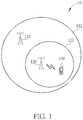
- Fig. 1 is a schematic diagram of a wireless communication system 10 for a dual connectivity (DC) scenario according to an example of the present invention.
- the wireless communication system 10 operates a long-term evolution (LTE) communication system and a fifth generation (5G) communication system, and includes a master base station (MBS) 110, a secondary BS (SBS) 120, and a communication device 130, but is not limited herein.
- the MBS 110 may be a macro cell BS, and may provide a first coverage area 112.
- the SBS 120 may be a small cell BS, and may provide a second coverage area 122 which is smaller than the first coverage area 112.
- the second coverage area 122 may overlap completely with the first coverage area 112, or may be partially outside the first coverage area 112.
- the communication device 130 in DC is dually connected to the MBS 110 and the SBS 120. That is, the communication device 130 may be capable of performing downlink (DL) receptions from both the first cell of the MBS 110 and the second cell of the SBS 120. It should be noted that the MBS 110 and the SBS 120 may operate on the same or different carriers.
- a communication device may be a user equipment (UE), a mobile phone, a laptop, a tablet computer, an electronic book, a portable computer system, a vehicle, a ship or an aircraft.
- the network and the communication device can be seen as a transmitter or a receiver according to direction (i.e. , transmission direction), e.g., for an uplink (UL), the communication device is the transmitter and the network is the receiver, and for a DL, the network is the transmitter and the communication device is the receiver.
- direction i.e. , transmission direction
- Fig. 2 is a schematic diagram of a communication device 20 according to an example of the present invention.
- the communication device 20 may be a communication device or the network shown in Fig. 1 , but is not limited herein.
- the communication device 20 may include at least one processing circuit 200 such as microprocessor (s) or Application Specific Integrated Circuit (s), at least one storage device 210 and at least one communication interfacing device 220.
- the at least one storage device 210 may be any data storage device that may store program codes 214, accessed and executed by the at least one processing circuit 200.
- each of the at least one storage device 210 examples include but are not limited to a subscriber identity module, read-only memory, flash memory, random-access memory, hard disk, optical data storage device, non-volatile storage device, non-transitory computer-readable medium (e.g., tangible media), etc.
- the at least one communication interfacing device 220 includes at least one transceiver and is used to transmit and receive signals (e.g., data, messages and/or packets) according to processing results of the at least one processing circuit 200.
- a radio bearer may be a data radio bearer (DRB) for user plane data transmission and/or reception or a signaling radio bearer (SRB) for control plane data transmission and/or reception.
- DRB configuration may include a DRB identity, a Packet Data Convergence Protocol (PDCP) configuration (e.g., a header compression configuration or a reordering timer), a logical channel identity and/or a logical channel configuration (e.g., a priority and a logical channel group).
- PDCP Packet Data Convergence Protocol
- a SRB configuration may include a SRB identity, a Radio Link Control (RLC) configuration and/or a logic channel configuration.
- RLC Radio Link Control
- DC radio bearers there may be at least three types of DC radio bearers: a master cell group (MCG) bearer, a secondary cell group (SCG) bearer and a split bearer.
- MCG bearer utilizes radio protocols only located in a MBS (e.g., the MBS 110) to use MBS resources.
- SCG bearer utilizes radio protocols only located in a SBS (e.g., the SBS 120) to use SBS resources.
- the split bearer utilizes radio protocols located in both the MBS (e.g., the MBS 110) and the SBS (e.g., the SBS 120) to use both the MBS resources and the SBS resources.
- the split bearer can be established via MCG bearer (i.e., MCG split bearer) or via SCG bearer (i.e., SCG split bearer).
- the DRB or the SRB may be the MCG bearer, the SCG bearer or the split bearer.
- the MBS or the SBS may be an evolved Node-B (eNB), an enhanced LTE (eLTE) eNB or a gNB.
- eNB evolved Node-B
- eLTE enhanced LTE
- the MBS is the eNB or the eLTE eNB
- the SBS is the gNB.
- the MBS is the gNB
- the SBS is the eNB or the eLTE eNB.
- LTE DC the MBS and the SBS are eNBs or eLTE eNBs.
- 5G DC the MBS and the SBS are gNBs.
- a UE is used to represent a communication device 130 in Fig. 1 , to simplify the illustration of the embodiments.
- a MBS may be the MBS 110 in Fig. 1
- a SBS may be the SBS 120 in Fig. 1 .
- a process 30 as shown in Fig. 3 is utilized in a UE, to handle communications in a DC, and includes the following steps:
- the UE transmits a third RRC message to the MBS or the SBS, wherein the third RRC message indicates a first reconfiguration failure on the second configuration or the conflict between the first configuration and the second configuration.
- the MBS when the MBS receives the third RRC message, the MBS transmits a message to the SBS, wherein the message indicates the first reconfiguration failure or the conflict between the first configuration and the second configuration.
- the SBS when the SBS receives the third RRC message, the SBS may know that the first reconfiguration failure or the conflict between the first configuration and the second configuration occurs. The UE does not apply the second configuration.
- the UE transmits the third RRC message on the first SRB to the MBS or on the second SRB to the SBS.
- the UE receives a third configuration in a first RRC reconfiguration message (e.g. , RRC Connection Reconfiguration message) on the first SRB from the MBS.
- the third configuration configures or reconfigures a parameter used by the UE to communicate with the MBS.
- the UE determines a second reconfiguration failure, if the third configuration is invalid. Then, the UE performs a first RRC connection reestablishment procedure in response to the second reconfiguration failure.
- the UE establishes the first SRB to the MBS on at least one first carrier.
- the UE receives a second RRC reconfiguration message on the first SRB from the MBS, wherein the second RRC reconfiguration message configures the UE to connect to the SBS on at least one second carrier.
- the UE determines a third reconfiguration failure according to a fourth configuration for communication with the SBS in the second RRC reconfiguration message .
- the MBS and the SBS are in the same radio access technology (RAT) such as LTE or 5G or different RATs. That is, the fourth configuration is invalid.
- the UE performs a second RRC connection reestablishment procedure in response to the third reconfiguration failure.
- RAT radio access technology
- the UE applies the first configuration and the second configuration, when detecting no conflict between the first configuration and the second configuration.
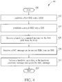
- a process 40 as shown in Fig. 4 is utilized in a UE, to handle communications in a DC, and includes the following steps:
- the UE receives the handover command message, when receiving or processing the RRC message. In one example, the UE receives the RRC message, when receiving or processing the handover command message. The RRC message does not trigger a handover for the UE.
- the UE ignores the RRC message by discarding the RRC message. In one example, the UE ignores the RRC message by not applying at least one configuration in the RRC message.
- the handover command message includes (or simply is) a first LTE RRC Connection Reconfiguration message or a first NR RRC Reconfiguration message.
- the RRC message includes (or simply is) a second LTE RRC Connection Reconfiguration message or a second NR RRC Reconfiguration message.
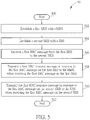
- a process 50 as shown in Fig. 5 is utilized in a UE, to handle communications in a DC, and includes the following steps:
- the MBS when the MBS receives the first RRC message from the SBS, the MBS transmits the first RRC message on the first SRB to the UE or transmits a second RRC message including the first RRC message on the first SRB to the UE.
- the UE transmits the first RRC response message on the first SRB to the MBS in response to the first RRC message or transmits a second RRC response message including the first RRC response message on the first SRB to the MBS in response to the second RRC message including the first RRC message.
- the MBS receives the first RRC response message or the second RRC response message on the first SRB, the MBS knows that the first RRC message or the second RRC message has been received by the UE. Then, the MBS transmits a message to the SBS or forwards the first RRC response to the SBS.
- the SBS knows that the first RRC message has been received by the UE.
- the SBS when the SBS receives the first RRC response message on the second SRB from the UE, the SBS knows that the first RRC message transmitted on the second SRB has been received by the UE. In one example, when the SBS receives the first RRC response message on the second SRB from the UE, the SBS transmits a message to the MBS to inform that a reconfiguration of a SBS configuration (e.g. , any of a measurement configuration, a SCG DRB configuration, a Media Access Control (MAC) configuration, a RLC configuration, etc.), a SCG change or a SBS change has been done successfully.
- a reconfiguration of a SBS configuration e.g. , any of a measurement configuration, a SCG DRB configuration, a Media Access Control (MAC) configuration, a RLC configuration, etc.
- a process 60 as shown in Fig. 6 is utilized in a UE, to handle communications in a DC, and includes the following steps:
- the first RRC message confiures the second SRB to the UE, configures a SCG DRB to the UE, changes the SBS, releases the second SRB, or releases the SBS.
- the second RRC message is configures (e.g., modifies or releases) a SCG DRB to the UE, configures (e.g., adds or releases) a secondary cell (SCell) of the SBS, changes a primary SCell of the SBS, or configures (or reconfigures) a measurement configuration to the UE.
- SCell secondary cell
- the MBS when the MBS receives the first RRC message from the SBS, the MBS transmits the first RRC message on the first SRB to the UE or transmits a third RRC message including the first RRC message on the first SRB to the UE.
- the UE transmits the first RRC response message on the first SRB to the MBS in response to the first message or transmits a third RRC response message including the first RRC response message on the first SRB to the MBS in response to the third RRC message including the first RRC message.
- the MBS receives the first RRC response message or the third RRC response message on the first SRB, the MBS knows that the first RRC message or the third RRC message has been received by the UE. Then, the MBS transmits a message to the SBS or forwards the first RRC response to the SBS.
- the SBS knows that the first RRC message has been received by the UE.
- the SBS when the SBS receives the second RRC response message on the second SRB from the UE, the SBS knows that the second RRC message transmitted on the second SRB has been received by the UE. In one example, when the SBS receives the second RRC response message on the second SRB from the UE, the SBS transmits a message to the MBS to inform that a reconfiguration of a SBS configuration, a SCG change or a SBS change has been done successfully.
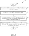
- a process 70 as shown in Fig. 7 is utilized in a first BS (e.g. , a SBS for a UE), to handle communications in a DC, and includes the following steps:
- the second RRC message configures (e.g., modifies or releases) a SCG DRB to the UE, configures (e.g., adds or releases) a SCell of the SBS, changes a primary SCell of the SBS, or configures (or reconfigures) a measurement configuration to the UE.
- the first RRC message includes (or simply is) a first LTE RRC Connection Reconfiguration message, and the first RRC response message includes (or simply is) a first LTE RRC Connection Reconfiguration Complete message.
- the first RRC message includes (or simply is) a first NR RRC Reconfiguration message, and the first RRC response message includes (or simply is) a first NR RRC Reconfiguration Complete message.
- the second RRC message includes (or simply is) a second LTE RRC Connection Reconfiguration message, and the second RRC response message includes (or simply is) a second LTE RRC Connection Reconfiguration Complete message.
- the second RRC message includes (or simply is) a second NR RRC Reconfiguration message
- the second RRC response message includes (or simply is) a second NR RRC Reconfiguration Complete message.
- the third RRC message includes (or simply is) a third LTE RRC Connection Reconfiguration message
- the third RRC response message includes (or simply is) a third LTE RRC Connection Reconfiguration Complete message.
- the third RRC message includes (or simply is) a third NR RRC Reconfiguration message
- the third RRC response message includes (or simply is) a third NR RRC Reconfiguration Complete message.
- the first SRB is a MCG SRB
- the second SRB is a SCG SRB.
- the UE establishes the first SRB in a RRC connection establishment procedure (e.g., upon receiving a RRC Connection Setup message of the RRC connection establishment procedure) with the MBS, and establishes the second SRB in a RRC connection reconfiguration procedure (e.g., upon receiving a RRC Connection Reconfiguration message of the RRC connection reconfiguration procedure) with the MBS.
- the first RRC message, the second RRC message and the third RRC message may be replaced by a first RRC configuration, a second RRC configuration and a third RRC configuration, respectively.
- the UE connects to the MBS on at least one first carrier and connects to the SBS on at least one second carrier.
- the UE and the MBS communicate the RRC messages above on the first SRB on the at least one first carrier.
- the UE and the SBS communicate the RRC messages above on the second SRB on the at least one second carrier.
- the at least one first carrier and the at least one second carrier include the same carrier (s) or different carriers.
- the at least one first carrier and the at least one second carrier have the same bandwidth or different bandwidths.
- the at least one first carrier and the at least one second carrier have different center frequencies or different frequency channel numbers. In one example, the at least one first carrier and the at least one second carrier have the same center frequency or the same frequency channel number but have different bandwidths.
- the present invention provides a method and a communication device for handling communications in a DC. Accordingly, the problem of handling the communications in the DC is solved.
Landscapes
- Engineering & Computer Science (AREA)
- Computer Networks & Wireless Communication (AREA)
- Signal Processing (AREA)
- Computer Security & Cryptography (AREA)
- Computing Systems (AREA)
- Computer Hardware Design (AREA)
- General Engineering & Computer Science (AREA)
- Health & Medical Sciences (AREA)
- General Health & Medical Sciences (AREA)
- Medical Informatics (AREA)
- Mobile Radio Communication Systems (AREA)
Abstract
Description
- This application claims the benefit of
U.S. Provisional Application No. 62/468,927, filed on Mar. 8, 2017 - The present invention relates to a device and a method used in a wireless communication system, and more particularly, to a device and a method of handling communications in a dual connectivity.
- In a long-term evolution (LTE) system, a radio resource control (RRC) connection reconfiguration procedure is used to configure radio bearers (RBs), handover, measurements, carrier aggregation or dual connectivity.
- The present invention therefore provides a communication device and method for handling communications in a dual connectivity to solve the abovementioned problem.
- A communication device for handling communications in a dual connectivity comprises a storage device for storing instructions and a processing circuit coupled to the storage device. The storage device stores, and the processing circuit is configured to execute instructions of establishing a first signaling radio bearer (SRB) with a master base station (MBS); establishing a second SRB with a secondary BS (SBS) ; receiving a first radio resource control (RRC) message comprising a first configuration, on the first SRB from the MBS; receiving a second RRC message comprising a second configuration, on the second SRB from the SBS; and applying the first configuration and ignoring the second configuration, when detecting a conflict between the first configuration and the second configuration.
- A communication device for handling communications in a dual connectivity comprises a storage device for storing instructions and a processing circuit coupled to the storage device. The storage device stores, and the processing circuit is configured to execute instructions of establishing a first SRB with a MBS; establishing a second SRB with a SBS; receiving a handover command message on the first SRB from the MBS; receiving a RRC message on the second SRB from the SBS; and performing a handover according to the handover command message and ignoring the RRC message.
- A communication device for handling communications in a dual connectivity comprises a storage device for storing instructions and a processing circuit coupled to the storage device. The storage device stores, and the processing circuit is configured to execute instructions of establishing a first SRB with a MBS; establishing a second SRB with a SBS; transmitting a first RRC response message on the first SRB in response to a first RRC message, when receiving the first RRC message on the first SRB; and transmitting a second RRC response message on the second SRB in response to a second RRC message, when receiving the second RRC message on the second SRB.
- These and other objectives of the present invention will no doubt become obvious to those of ordinary skill in the art after reading the following detailed description of the preferred embodiment that is illustrated in the various figures and drawings.
-
-
Fig. 1 is a schematic diagram of a wireless communication system for a dual connectivity scenario according to an example of the present invention. -
Fig. 2 is a schematic diagram of a communication device according to an example of the present invention. -
Fig. 3 is a flowchart of a process according to an example of the present invention. -
Fig. 4 is a flowchart of a process according to an example of the present invention. -
Fig. 5 is a flowchart of a process according to an example of the present invention. -
Fig. 6 is a flowchart of a process according to an example of the present invention. -
Fig. 7 is a flowchart of a process according to an example of the present invention. -
Fig. 1 is a schematic diagram of awireless communication system 10 for a dual connectivity (DC) scenario according to an example of the present invention. Thewireless communication system 10 operates a long-term evolution (LTE) communication system and a fifth generation (5G) communication system, and includes a master base station (MBS) 110, a secondary BS (SBS) 120, and acommunication device 130, but is not limited herein. The MBS 110 may be a macro cell BS, and may provide afirst coverage area 112. The SBS 120 may be a small cell BS, and may provide asecond coverage area 122 which is smaller than thefirst coverage area 112. Thesecond coverage area 122 may overlap completely with thefirst coverage area 112, or may be partially outside thefirst coverage area 112. Thecommunication device 130 in DC is dually connected to the MBS 110 and the SBS 120. That is, thecommunication device 130 may be capable of performing downlink (DL) receptions from both the first cell of theMBS 110 and the second cell of the SBS 120. It should be noted that the MBS 110 and the SBS 120 may operate on the same or different carriers. - A communication device may be a user equipment (UE), a mobile phone, a laptop, a tablet computer, an electronic book, a portable computer system, a vehicle, a ship or an aircraft. In addition, the network and the communication device can be seen as a transmitter or a receiver according to direction (i.e. , transmission direction), e.g., for an uplink (UL), the communication device is the transmitter and the network is the receiver, and for a DL, the network is the transmitter and the communication device is the receiver.
-
Fig. 2 is a schematic diagram of acommunication device 20 according to an example of the present invention. Thecommunication device 20 may be a communication device or the network shown inFig. 1 , but is not limited herein. Thecommunication device 20 may include at least oneprocessing circuit 200 such as microprocessor (s) or Application Specific Integrated Circuit (s), at least onestorage device 210 and at least onecommunication interfacing device 220. The at least onestorage device 210 may be any data storage device that may storeprogram codes 214, accessed and executed by the at least oneprocessing circuit 200. Examples of each of the at least onestorage device 210 include but are not limited to a subscriber identity module, read-only memory, flash memory, random-access memory, hard disk, optical data storage device, non-volatile storage device, non-transitory computer-readable medium (e.g., tangible media), etc. The at least onecommunication interfacing device 220 includes at least one transceiver and is used to transmit and receive signals (e.g., data, messages and/or packets) according to processing results of the at least oneprocessing circuit 200. - A radio bearer (RB) may be a data radio bearer (DRB) for user plane data transmission and/or reception or a signaling radio bearer (SRB) for control plane data transmission and/or reception. A DRB configuration may include a DRB identity, a Packet Data Convergence Protocol (PDCP) configuration (e.g., a header compression configuration or a reordering timer), a logical channel identity and/or a logical channel configuration (e.g., a priority and a logical channel group). A SRB configuration may include a SRB identity, a Radio Link Control (RLC) configuration and/or a logic channel configuration.
- In DC, there may be at least three types of DC radio bearers: a master cell group (MCG) bearer, a secondary cell group (SCG) bearer and a split bearer. The MCG bearer utilizes radio protocols only located in a MBS (e.g., the MBS 110) to use MBS resources. The SCG bearer utilizes radio protocols only located in a SBS (e.g., the SBS 120) to use SBS resources. The split bearer utilizes radio protocols located in both the MBS (e.g., the MBS 110) and the SBS (e.g., the SBS 120) to use both the MBS resources and the SBS resources. The split bearer can be established via MCG bearer (i.e., MCG split bearer) or via SCG bearer (i.e., SCG split bearer). In general, the DRB or the SRB may be the MCG bearer, the SCG bearer or the split bearer. The MBS or the SBS may be an evolved Node-B (eNB), an enhanced LTE (eLTE) eNB or a gNB. In DC in the LTE system and the 5G system, the MBS is the eNB or the eLTE eNB, and the SBS is the gNB. In one example, the MBS is the gNB, and the SBS is the eNB or the eLTE eNB. In LTE DC, the MBS and the SBS are eNBs or eLTE eNBs. In 5G DC, the MBS and the SBS are gNBs.
- In the following examples, a UE is used to represent a
communication device 130 inFig. 1 , to simplify the illustration of the embodiments. A MBS may be the MBS 110 inFig. 1 , and a SBS may be the SBS 120 inFig. 1 . - A
process 30 as shown inFig. 3 is utilized in a UE, to handle communications in a DC, and includes the following steps: - Step 300:
- Start.
- Step 302:
- Establish a first SRB with a MBS.
- Step 304:
- Establish a second SRB with a SBS.
- Step 306:
- Receive a first radio resource control (RRC) message comprising a first configuration, on the first SRB from the MBS.
- Step 308:
- Receive a second RRC message comprising a second configuration, on the second SRB from the SBS.
- Step 310:
- Apply the first configuration and ignore the second configuration, when detecting a conflict between the first configuration and the second configuration.
- Step 312:
- End.
- The following examples may be applied to the
process 30. - In one example, the UE transmits a third RRC message to the MBS or the SBS, wherein the third RRC message indicates a first reconfiguration failure on the second configuration or the conflict between the first configuration and the second configuration. In one example, when the MBS receives the third RRC message, the MBS transmits a message to the SBS, wherein the message indicates the first reconfiguration failure or the conflict between the first configuration and the second configuration. In one example, when the SBS receives the third RRC message, the SBS may know that the first reconfiguration failure or the conflict between the first configuration and the second configuration occurs. The UE does not apply the second configuration. In one example, the UE transmits the third RRC message on the first SRB to the MBS or on the second SRB to the SBS.
- In one example, the UE receives a third configuration in a first RRC reconfiguration message (e.g. , RRC Connection Reconfiguration message) on the first SRB from the MBS. The third configuration configures or reconfigures a parameter used by the UE to communicate with the MBS. The UE determines a second reconfiguration failure, if the third configuration is invalid. Then, the UE performs a first RRC connection reestablishment procedure in response to the second reconfiguration failure.
- In one example, the UE establishes the first SRB to the MBS on at least one first carrier. The UE receives a second RRC reconfiguration message on the first SRB from the MBS, wherein the second RRC reconfiguration message configures the UE to connect to the SBS on at least one second carrier. The UE determines a third reconfiguration failure according to a fourth configuration for communication with the SBS in the second RRC reconfiguration message . The MBS and the SBS are in the same radio access technology (RAT) such as LTE or 5G or different RATs. That is, the fourth configuration is invalid. The UE performs a second RRC connection reestablishment procedure in response to the third reconfiguration failure.
- In one example, the UE applies the first configuration and the second configuration, when detecting no conflict between the first configuration and the second configuration.
- A
process 40 as shown inFig. 4 is utilized in a UE, to handle communications in a DC, and includes the following steps: - Step 400:
- Start.
- Step 402:
- Establish a first SRB with a MBS.
- Step 404:
- Establish a second SRB with a SBS.
- Step 406:
- Receive a handover command message on the first SRB from the MBS.
- Step 408:
- Receive a RRC message on the second SRB from the SBS.
- Step 410:
- Perform a handover according to the handover command message and ignore the RRC message.
- Step 412:
- End.
- The following examples may be applied to the
process 40. - In one example, the UE receives the handover command message, when receiving or processing the RRC message. In one example, the UE receives the RRC message, when receiving or processing the handover command message. The RRC message does not trigger a handover for the UE.
- In one example, the UE ignores the RRC message by discarding the RRC message. In one example, the UE ignores the RRC message by not applying at least one configuration in the RRC message.
- In one example, the handover command message includes (or simply is) a first LTE RRC Connection Reconfiguration message or a first NR RRC Reconfiguration message. In one example, the RRC message includes (or simply is) a second LTE RRC Connection Reconfiguration message or a second NR RRC Reconfiguration message.
- A
process 50 as shown inFig. 5 is utilized in a UE, to handle communications in a DC, and includes the following steps: - Step 500:
- Start.
- Step 502:
- Establish a first SRB with a MBS.
- Step 504:
- Establish a second SRB with a SBS.
- Step 506:
- Receive a first RRC message on the first SRB or the second SRB.
- Step 508:
- Transmit a first RRC response message in response to the first RRC message on the first SRB to the MBS, when receiving the first RRC message on the first SRB.
- Step 510:
- Transmit the first RRC response message in response to the first RRC message on the second SRB to the SBS, when receiving the first RRC message on the second SRB.
- Step 512:
- End.
- The following examples may be applied to the
process 50. - In one example, when the MBS receives the first RRC message from the SBS, the MBS transmits the first RRC message on the first SRB to the UE or transmits a second RRC message including the first RRC message on the first SRB to the UE. The UE transmits the first RRC response message on the first SRB to the MBS in response to the first RRC message or transmits a second RRC response message including the first RRC response message on the first SRB to the MBS in response to the second RRC message including the first RRC message. When the MBS receives the first RRC response message or the second RRC response message on the first SRB, the MBS knows that the first RRC message or the second RRC message has been received by the UE. Then, the MBS transmits a message to the SBS or forwards the first RRC response to the SBS. Thus, the SBS knows that the first RRC message has been received by the UE.
- In one example, when the SBS receives the first RRC response message on the second SRB from the UE, the SBS knows that the first RRC message transmitted on the second SRB has been received by the UE. In one example, when the SBS receives the first RRC response message on the second SRB from the UE, the SBS transmits a message to the MBS to inform that a reconfiguration of a SBS configuration (e.g. , any of a measurement configuration, a SCG DRB configuration, a Media Access Control (MAC) configuration, a RLC configuration, etc.), a SCG change or a SBS change has been done successfully.
- A
process 60 as shown inFig. 6 is utilized in a UE, to handle communications in a DC, and includes the following steps: - Step 600:
- Start.
- Step 602:
- Establish a first SRB with a MBS.
- Step 604:
- Establish a second SRB with a SBS.
- Step 606:
- Transmit a first RRC response message on the first SRB in response to a first RRC message, when receiving the first RRC message on the first SRB.
- Step 608:
- Transmit a second RRC response message on the second SRB in response to a second RRC message, when receiving the second RRC message on the second SRB.
- Step 610:
- End.
- The following examples may be applied to the
process 60. - In one example, the first RRC message confiures the second SRB to the UE, configures a SCG DRB to the UE, changes the SBS, releases the second SRB, or releases the SBS. In one example, the second RRC message is configures (e.g., modifies or releases) a SCG DRB to the UE, configures (e.g., adds or releases) a secondary cell (SCell) of the SBS, changes a primary SCell of the SBS, or configures (or reconfigures) a measurement configuration to the UE.
- In one example, when the MBS receives the first RRC message from the SBS, the MBS transmits the first RRC message on the first SRB to the UE or transmits a third RRC message including the first RRC message on the first SRB to the UE. The UE transmits the first RRC response message on the first SRB to the MBS in response to the first message or transmits a third RRC response message including the first RRC response message on the first SRB to the MBS in response to the third RRC message including the first RRC message. When the MBS receives the first RRC response message or the third RRC response message on the first SRB, the MBS knows that the first RRC message or the third RRC message has been received by the UE. Then, the MBS transmits a message to the SBS or forwards the first RRC response to the SBS. Thus, the SBS knows that the first RRC message has been received by the UE.
- In one example, when the SBS receives the second RRC response message on the second SRB from the UE, the SBS knows that the second RRC message transmitted on the second SRB has been received by the UE. In one example, when the SBS receives the second RRC response message on the second SRB from the UE, the SBS transmits a message to the MBS to inform that a reconfiguration of a SBS configuration, a SCG change or a SBS change has been done successfully.
- A
process 70 as shown inFig. 7 is utilized in a first BS (e.g. , a SBS for a UE), to handle communications in a DC, and includes the following steps: - Step 700:
- Start.
- Step 702:
- Connect to a MBS which connects to the UE and configures a first SRB to the UE.
- Step 704:
- Configure a second SRB to the UE via the MBS.
- Step 706:
- Determine to transmit a first RRC message to the UE via the MBS, when the first RRC message configures a SBS change to a second BS for the UE.
- Step 708:
- Determine to transmit a second RRC message on the second SRB to the UE, when the second RRC message does not configure the SBS change.
- Step 710:
- End.
- The following examples may be applied to the
process 70. - In one example, the second RRC message configures (e.g., modifies or releases) a SCG DRB to the UE, configures (e.g., adds or releases) a SCell of the SBS, changes a primary SCell of the SBS, or configures (or reconfigures) a measurement configuration to the UE.
- The following examples may be applied to the processes 30-70.
- In one example, the first RRC message includes (or simply is) a first LTE RRC Connection Reconfiguration message, and the first RRC response message includes (or simply is) a first LTE RRC Connection Reconfiguration Complete message. In one example, the first RRC message includes (or simply is) a first NR RRC Reconfiguration message, and the first RRC response message includes (or simply is) a first NR RRC Reconfiguration Complete message. In one example, the second RRC message includes (or simply is) a second LTE RRC Connection Reconfiguration message, and the second RRC response message includes (or simply is) a second LTE RRC Connection Reconfiguration Complete message. In one example, the second RRC message includes (or simply is) a second NR RRC Reconfiguration message, and the second RRC response message includes (or simply is) a second NR RRC Reconfiguration Complete message. In one example, the third RRC message includes (or simply is) a third LTE RRC Connection Reconfiguration message, and the third RRC response message includes (or simply is) a third LTE RRC Connection Reconfiguration Complete message. In one example, the third RRC message includes (or simply is) a third NR RRC Reconfiguration message, and the third RRC response message includes (or simply is) a third NR RRC Reconfiguration Complete message.
- In one example, the first SRB is a MCG SRB, and the second SRB is a SCG SRB. The UE establishes the first SRB in a RRC connection establishment procedure (e.g., upon receiving a RRC Connection Setup message of the RRC connection establishment procedure) with the MBS, and establishes the second SRB in a RRC connection reconfiguration procedure (e.g., upon receiving a RRC Connection Reconfiguration message of the RRC connection reconfiguration procedure) with the MBS.
- In one example, the first RRC message, the second RRC message and the third RRC message may be replaced by a first RRC configuration, a second RRC configuration and a third RRC configuration, respectively.
- In one example, the UE connects to the MBS on at least one first carrier and connects to the SBS on at least one second carrier. The UE and the MBS communicate the RRC messages above on the first SRB on the at least one first carrier. The UE and the SBS communicate the RRC messages above on the second SRB on the at least one second carrier. In one example, the at least one first carrier and the at least one second carrier include the same carrier (s) or different carriers. In one example, the at least one first carrier and the at least one second carrier have the same bandwidth or different bandwidths.
- In one example, the at least one first carrier and the at least one second carrier have different center frequencies or different frequency channel numbers. In one example, the at least one first carrier and the at least one second carrier have the same center frequency or the same frequency channel number but have different bandwidths.
- Those skilled in the art should readily make combinations, modifications and/or alterations on the abovementioned description and examples. For example, the skilled person easily makes new embodiments of the network based on the embodiments and examples of the UE, and makes new embodiments of the UE based on the embodiments and examples of the network. The abovementioned description, steps and/or processes including suggested steps can be realized by means that could be hardware, software, firmware (known as a combination of a hardware device and computer instructions and data that reside as read-only software on the hardware device), an electronic system, or combination thereof. An example of the means may be the
communication device 20. Any of the above processes and examples above may be compiled into theprogram codes 214. - To sum up, the present invention provides a method and a communication device for handling communications in a DC. Accordingly, the problem of handling the communications in the DC is solved.
Claims (14)
- A communication device for handling communications in a dual connectivity, comprising:a storage device; anda processing circuit, coupled to the storage device, wherein the storage device stores, and the processing circuit is configured to execute instructions of:establishing a first signaling radio bearer (SRB) with a master base station (MBS);establishing a second SRB with a secondary BS (SBS);receiving a first radio resource control (RRC) message comprising a first configuration, on the first SRB from the MBS;receiving a second RRC message comprising a second configuration, on the second SRB from the SBS; andapplying the first configuration and ignoring the second configuration, when detecting a conflict between the first configuration and the second configuration.
- The communication device of claim 1, wherein the instructions further comprise:transmitting a third RRC message to the MBS or the SBS, wherein the third RRC message indicates a first reconfiguration failure on the second configuration or the conflict between the first configuration and the second configuration.
- The communication device of claim 1, wherein the instructions further comprise:receiving a third configuration in a first RRC reconfiguration message on the first SRB from the MBS;determining a second reconfiguration failure, if the third configuration is invalid; andperforming a RRC connection reestablishment procedure in response to the second reconfiguration failure.
- The communication device of claim 1, wherein the first RRC message comprises a first long-term evolution (LTE) RRC Connection Reconfiguration message or a first new radio (NR) RRC Reconfiguration message, and the second RRC message comprises a second LTE RRC Connection Reconfiguration message or a second NR RRC Reconfiguration message.
- A communication device for handling communications in a dual connectivity, comprising:a storage device; anda processing circuit, coupled to the storage device, wherein the storage device stores, and the processing circuit is configured to execute instructions of:establishing a first signaling radio bearer (SRB) with a master base station (MBS);establishing a second SRB with a secondary BS (SBS);receiving a handover command message on the first SRB from the MBS;receiving a radio resource control (RRC) message on the second SRB from the SBS; andperforming a handover according to the handover command message and ignoring the RRC message.
- The communication device of claim 5, wherein the instructions further comprise:receiving the handover command message, when processing the RRC message; orreceiving the RRC message, when processing the handover command message.
- A communication device for handling communications in a dual connectivity, comprising:a storage device; anda processing circuit, coupled to the storage device, wherein the storage device stores, and the processing circuit is configured to execute instructions of:establishing a first signaling radio bearer (SRB) with a master base station (MBS);establishing a second SRB with a secondary BS (SBS);transmitting a first radio resource control (RRC) response message on the first SRB in response to a first RRC message, when receiving the first RRC message on the first SRB; andtransmitting a second RRC response message on the second SRB in response to a second RRC message, when receiving the second RRC message on the second SRB.
- The communication device of claim 7, wherein the first RRC message configures the second SRB to the communication device, configures a secondary cell group (SCG) data radio bearer (DRB) to the communication device, changes the SBS, releases the second SRB, or releases the SBS.
- The communication device of claim 7, wherein the second RRC message is configures a SCG DRB to the communication device, configures a secondary cell (SCell) of the SBS, changes a primary SCell of the SBS, or configures a measurement configuration to the communication device.
- The communication device of claim 7, wherein the instructions further comprise:receiving the first RRC message on the first SRB from the MBS, when the MBS receives the first RRC message from the SBS; andtransmitting the first RRC response message on the first SRB to the MBS in response to the first RRC message.
- The communication device of claim 7, wherein the instructions further comprise:receiving a third RRC message comprising the first RRC message on the first SRB from the MBS, when the MBS receives the first RRC message from the SBS; andtransmitting a third RRC response message comprising the first RRC response message on the first SRB to the MBS in response to the third RRC message comprising the first RRC message.
- The communication device of claim 11, wherein the third RRC message comprises a third long-term evolution (LTE) RRC Connection Reconfiguration message and the third RRC response message comprises a third LTE RRC Connection Reconfiguration Complete message, or the third RRC message comprises a third new radio (NR) RRC Reconfiguration message and the third RRC response message comprises a third NR RRC Reconfiguration Complete message.
- The communication device of claim 7, wherein the first RRC message comprises a first LTE RRC Connection Reconfiguration message and the first RRC response message comprises a first LTE RRC Connection Reconfiguration Complete message, or the first RRC message comprises a first NR RRC Reconfiguration message and the first RRC response message comprises a first NR RRC Reconfiguration Complete message.
- The communication device of claim 7, wherein the second RRC message comprises a second LTE RRC Connection Reconfiguration message and the second RRC response message comprises a second LTE RRC Connection Reconfiguration Complete message, or the second RRC message comprises a second NR RRC Reconfiguration message and the second RRC response message comprises a second NR RRC Reconfiguration Complete message.
Applications Claiming Priority (1)
| Application Number | Priority Date | Filing Date | Title |
|---|---|---|---|
| US201762468927P | 2017-03-08 | 2017-03-08 |
Publications (2)
| Publication Number | Publication Date |
|---|---|
| EP3373694A1 true EP3373694A1 (en) | 2018-09-12 |
| EP3373694B1 EP3373694B1 (en) | 2022-06-08 |
Family
ID=63077602
Family Applications (1)
| Application Number | Title | Priority Date | Filing Date |
|---|---|---|---|
| EP18160656.7A Active EP3373694B1 (en) | 2017-03-08 | 2018-03-08 | Communication device and method for handling communications in a dual connectivity |
Country Status (4)
| Country | Link |
|---|---|
| US (1) | US11057953B2 (en) |
| EP (1) | EP3373694B1 (en) |
| CN (1) | CN108574993B (en) |
| TW (1) | TWI754018B (en) |
Families Citing this family (3)
| Publication number | Priority date | Publication date | Assignee | Title |
|---|---|---|---|---|
| WO2020113442A1 (en) * | 2018-12-04 | 2020-06-11 | Qualcomm Incorporated | Fast secondary cell group activation and deactivation using a suspended state |
| CN114650588B (en) * | 2019-03-09 | 2024-06-25 | 荣耀终端有限公司 | Network connection processing method, related equipment and computer storage medium |
| WO2021062677A1 (en) * | 2019-09-30 | 2021-04-08 | 华为技术有限公司 | Communication method and apparatus |
Citations (1)
| Publication number | Priority date | Publication date | Assignee | Title |
|---|---|---|---|---|
| US20140056243A1 (en) * | 2012-08-23 | 2014-02-27 | Interdigital Patent Holdings, Inc. | Operating with multiple schedulers in a wireless system |
Family Cites Families (8)
| Publication number | Priority date | Publication date | Assignee | Title |
|---|---|---|---|---|
| EP2757853B1 (en) | 2012-12-27 | 2017-09-20 | HTC Corporation | Methods for handling device to device communication and related communication device |
| CN103338518B (en) * | 2012-12-31 | 2016-12-28 | 上海华为技术有限公司 | A kind of send the method for RRC signaling, base station and system |
| WO2015037970A1 (en) | 2013-09-16 | 2015-03-19 | Lg Electronics Inc. | Method and apparatus for network synchronization |
| EP2854444A1 (en) * | 2013-09-27 | 2015-04-01 | Panasonic Intellectual Property Corporation of America | Efficient uplink scheduling mechanism for dual connectivity |
| US9713044B2 (en) * | 2014-01-30 | 2017-07-18 | Sharp Kabushiki Kaisha | Systems and methods for dual-connectivity operation |
| US9838945B2 (en) | 2014-04-14 | 2017-12-05 | Htc Corporation | Method of handling link failure and related communication device |
| CN106211352A (en) | 2015-05-04 | 2016-12-07 | 中兴通讯股份有限公司 | Method and device for establishing data radio bearer |
| US10624149B2 (en) * | 2017-02-03 | 2020-04-14 | Motorola Mobility Llc | Configuration information for an inactive state |
-
2018
- 2018-03-07 US US15/913,928 patent/US11057953B2/en active Active
- 2018-03-08 TW TW107107791A patent/TWI754018B/en active
- 2018-03-08 EP EP18160656.7A patent/EP3373694B1/en active Active
- 2018-03-08 CN CN201810189862.1A patent/CN108574993B/en active Active
Patent Citations (1)
| Publication number | Priority date | Publication date | Assignee | Title |
|---|---|---|---|---|
| US20140056243A1 (en) * | 2012-08-23 | 2014-02-27 | Interdigital Patent Holdings, Inc. | Operating with multiple schedulers in a wireless system |
Non-Patent Citations (6)
| Title |
|---|
| "3rd Generation Partnership Project; Technical Specification Group Radio Access Network; Evolved Universal Terrestrial Radio Access (E-UTRA); Radio Resource Control (RRC); Protocol specification (Release 14)", 3GPP STANDARD; 3GPP TS 36.331, 3RD GENERATION PARTNERSHIP PROJECT (3GPP), MOBILE COMPETENCE CENTRE ; 650, ROUTE DES LUCIOLES ; F-06921 SOPHIA-ANTIPOLIS CEDEX ; FRANCE, vol. RAN WG2, no. V14.1.0, 12 January 2017 (2017-01-12), pages 1 - 654, XP051230537 * |
| INTEL CORPORATION: "Discussion on NR SgNB configuration transfer", vol. RAN WG2, no. Spokane, USA; 20170117 - 20170119, 7 January 2017 (2017-01-07), XP051203966, Retrieved from the Internet <URL:http://www.3gpp.org/ftp/tsg_ran/WG2_RL2/TSGR2_AHs/2017_01_NR/Docs/> [retrieved on 20170107] * |
| NEC: "Direct RRC signalling on SCG in LTE-NR Dual Connectivity", vol. RAN WG2, no. Athens, Greece; 20170213 - 20170217, 12 February 2017 (2017-02-12), XP051212473, Retrieved from the Internet <URL:http://www.3gpp.org/ftp/Meetings_3GPP_SYNC/RAN2/Docs/> [retrieved on 20170212] * |
| NOKIA ET AL: "General considerations for LTE-NR tight interworking", vol. RAN WG2, no. Gothenburg, Sweden; 20160822 - 20160826, 21 August 2016 (2016-08-21), XP051126491, Retrieved from the Internet <URL:http://www.3gpp.org/ftp/Meetings_3GPP_SYNC/RAN2/Docs/> [retrieved on 20160821] * |
| NOKIA ET AL: "On UE capability and network node coordination aspects in LTE- NR tight interworking", vol. RAN WG2, no. Kaohsiung, Taiwan; 20161010 - 20161014, 9 October 2016 (2016-10-09), XP051150840, Retrieved from the Internet <URL:http://www.3gpp.org/ftp/Meetings_3GPP_SYNC/RAN2/Docs/> [retrieved on 20161009] * |
| NOKIA ET AL: "RRC aspects for the direct signalling path from secondary node to the UE", vol. RAN WG2, no. Spokane, USA; 20170117 - 20170119, 17 January 2017 (2017-01-17), XP051210642, Retrieved from the Internet <URL:http://www.3gpp.org/ftp/Meetings_3GPP_SYNC/RAN2/Docs/> [retrieved on 20170117] * |
Also Published As
| Publication number | Publication date |
|---|---|
| TW201834497A (en) | 2018-09-16 |
| TWI754018B (en) | 2022-02-01 |
| CN108574993A (en) | 2018-09-25 |
| US11057953B2 (en) | 2021-07-06 |
| US20180263072A1 (en) | 2018-09-13 |
| EP3373694B1 (en) | 2022-06-08 |
| CN108574993B (en) | 2021-04-06 |
Similar Documents
| Publication | Publication Date | Title |
|---|---|---|
| EP3439365B1 (en) | Base station and method of handling bandwidth parts | |
| US10313934B2 (en) | Device and method of handling communication | |
| EP3041310B1 (en) | Methods of handling simultaneous communications and related communication devices | |
| EP3689096B1 (en) | Methods and apparatuses for nr pdcp preservation upon rrc resume/suspend | |
| US10575349B2 (en) | Device and method for handling a new radio connection in inter-system mobility | |
| EP3346762A1 (en) | Handling a pdn connection in lte to nr/5g inter-system mobility | |
| EP3439422B1 (en) | Device and method supporting access to secondary cells for dual connectivity and handover | |
| US10873985B2 (en) | Device and method of handling a dual connectivity with base stations | |
| US10448447B2 (en) | Device and method for handling a bearer type change for a radio bearer | |
| EP3484205A1 (en) | Device and method of handling an evolved packet system bearer context in lte to nr/5g and nr/5g to lte inter system mobility | |
| US10548176B2 (en) | Device and method of handling dual connectivity | |
| EP3410816A1 (en) | Device and method for handling measurement configuration and signaling radio bearer | |
| EP3402308B1 (en) | Coordination between multirat base stations in dual connectivity | |
| EP3442267B1 (en) | Network for handling a bearer change in dual connectivity | |
| US11134531B2 (en) | Device and method of handling a dual connectivity | |
| US11057953B2 (en) | Device and method of handling communications in a dual connectivity | |
| EP3442265A1 (en) | Device and method for handling a packet data convergence protocol operation | |
| US10624151B2 (en) | Device and method of handling a signalling radio bearer configuration | |
| US20190053112A1 (en) | Device and Method of Handling a Secondary Node Change in Dual Connectivity | |
| EP3477992B1 (en) | Base station for handling radio bearer configurations of radio access technologies | |
| US20190053110A1 (en) | Device and Method of Handling a Bearer Change in Dual Connectivity |
Legal Events
| Date | Code | Title | Description |
|---|---|---|---|
| STAA | Information on the status of an ep patent application or granted ep patent |
Free format text: STATUS: EXAMINATION IS IN PROGRESS |
|
| PUAI | Public reference made under article 153(3) epc to a published international application that has entered the european phase |
Free format text: ORIGINAL CODE: 0009012 |
|
| 17P | Request for examination filed |
Effective date: 20180308 |
|
| AK | Designated contracting states |
Kind code of ref document: A1 Designated state(s): AL AT BE BG CH CY CZ DE DK EE ES FI FR GB GR HR HU IE IS IT LI LT LU LV MC MK MT NL NO PL PT RO RS SE SI SK SM TR |
|
| AX | Request for extension of the european patent |
Extension state: BA ME |
|
| RBV | Designated contracting states (corrected) |
Designated state(s): AL AT BE BG CH CY CZ DE DK EE ES FI FR GB GR HR HU IE IS IT LI LT LU LV MC MK MT NL NO PL PT RO RS SE SI SK SM TR |
|
| REG | Reference to a national code |
Ref country code: DE Ref legal event code: R079 Ref document number: 602018036401 Country of ref document: DE Free format text: PREVIOUS MAIN CLASS: H04W0076150000 Ipc: H04W0076120000 |
|
| GRAP | Despatch of communication of intention to grant a patent |
Free format text: ORIGINAL CODE: EPIDOSNIGR1 |
|
| STAA | Information on the status of an ep patent application or granted ep patent |
Free format text: STATUS: GRANT OF PATENT IS INTENDED |
|
| RIC1 | Information provided on ipc code assigned before grant |
Ipc: H04W 76/16 20180101ALN20211202BHEP Ipc: H04W 76/15 20180101ALI20211202BHEP Ipc: H04W 76/12 20180101AFI20211202BHEP |
|
| INTG | Intention to grant announced |
Effective date: 20211221 |
|
| GRAS | Grant fee paid |
Free format text: ORIGINAL CODE: EPIDOSNIGR3 |
|
| GRAA | (expected) grant |
Free format text: ORIGINAL CODE: 0009210 |
|
| STAA | Information on the status of an ep patent application or granted ep patent |
Free format text: STATUS: THE PATENT HAS BEEN GRANTED |
|
| AK | Designated contracting states |
Kind code of ref document: B1 Designated state(s): AL AT BE BG CH CY CZ DE DK EE ES FI FR GB GR HR HU IE IS IT LI LT LU LV MC MK MT NL NO PL PT RO RS SE SI SK SM TR |
|
| REG | Reference to a national code |
Ref country code: AT Ref legal event code: REF Ref document number: 1497790 Country of ref document: AT Kind code of ref document: T Effective date: 20220615 Ref country code: CH Ref legal event code: EP |
|
| REG | Reference to a national code |
Ref country code: DE Ref legal event code: R096 Ref document number: 602018036401 Country of ref document: DE |
|
| REG | Reference to a national code |
Ref country code: IE Ref legal event code: FG4D |
|
| REG | Reference to a national code |
Ref country code: LT Ref legal event code: MG9D |
|
| REG | Reference to a national code |
Ref country code: NL Ref legal event code: MP Effective date: 20220608 |
|
| PG25 | Lapsed in a contracting state [announced via postgrant information from national office to epo] |
Ref country code: SE Free format text: LAPSE BECAUSE OF FAILURE TO SUBMIT A TRANSLATION OF THE DESCRIPTION OR TO PAY THE FEE WITHIN THE PRESCRIBED TIME-LIMIT Effective date: 20220608 Ref country code: NO Free format text: LAPSE BECAUSE OF FAILURE TO SUBMIT A TRANSLATION OF THE DESCRIPTION OR TO PAY THE FEE WITHIN THE PRESCRIBED TIME-LIMIT Effective date: 20220908 Ref country code: LT Free format text: LAPSE BECAUSE OF FAILURE TO SUBMIT A TRANSLATION OF THE DESCRIPTION OR TO PAY THE FEE WITHIN THE PRESCRIBED TIME-LIMIT Effective date: 20220608 Ref country code: HR Free format text: LAPSE BECAUSE OF FAILURE TO SUBMIT A TRANSLATION OF THE DESCRIPTION OR TO PAY THE FEE WITHIN THE PRESCRIBED TIME-LIMIT Effective date: 20220608 Ref country code: GR Free format text: LAPSE BECAUSE OF FAILURE TO SUBMIT A TRANSLATION OF THE DESCRIPTION OR TO PAY THE FEE WITHIN THE PRESCRIBED TIME-LIMIT Effective date: 20220909 Ref country code: FI Free format text: LAPSE BECAUSE OF FAILURE TO SUBMIT A TRANSLATION OF THE DESCRIPTION OR TO PAY THE FEE WITHIN THE PRESCRIBED TIME-LIMIT Effective date: 20220608 Ref country code: ES Free format text: LAPSE BECAUSE OF FAILURE TO SUBMIT A TRANSLATION OF THE DESCRIPTION OR TO PAY THE FEE WITHIN THE PRESCRIBED TIME-LIMIT Effective date: 20220608 Ref country code: BG Free format text: LAPSE BECAUSE OF FAILURE TO SUBMIT A TRANSLATION OF THE DESCRIPTION OR TO PAY THE FEE WITHIN THE PRESCRIBED TIME-LIMIT Effective date: 20220908 |
|
| REG | Reference to a national code |
Ref country code: AT Ref legal event code: MK05 Ref document number: 1497790 Country of ref document: AT Kind code of ref document: T Effective date: 20220608 |
|
| PG25 | Lapsed in a contracting state [announced via postgrant information from national office to epo] |
Ref country code: RS Free format text: LAPSE BECAUSE OF FAILURE TO SUBMIT A TRANSLATION OF THE DESCRIPTION OR TO PAY THE FEE WITHIN THE PRESCRIBED TIME-LIMIT Effective date: 20220608 Ref country code: LV Free format text: LAPSE BECAUSE OF FAILURE TO SUBMIT A TRANSLATION OF THE DESCRIPTION OR TO PAY THE FEE WITHIN THE PRESCRIBED TIME-LIMIT Effective date: 20220608 |
|
| PG25 | Lapsed in a contracting state [announced via postgrant information from national office to epo] |
Ref country code: NL Free format text: LAPSE BECAUSE OF FAILURE TO SUBMIT A TRANSLATION OF THE DESCRIPTION OR TO PAY THE FEE WITHIN THE PRESCRIBED TIME-LIMIT Effective date: 20220608 |
|
| PG25 | Lapsed in a contracting state [announced via postgrant information from national office to epo] |
Ref country code: SM Free format text: LAPSE BECAUSE OF FAILURE TO SUBMIT A TRANSLATION OF THE DESCRIPTION OR TO PAY THE FEE WITHIN THE PRESCRIBED TIME-LIMIT Effective date: 20220608 Ref country code: SK Free format text: LAPSE BECAUSE OF FAILURE TO SUBMIT A TRANSLATION OF THE DESCRIPTION OR TO PAY THE FEE WITHIN THE PRESCRIBED TIME-LIMIT Effective date: 20220608 Ref country code: RO Free format text: LAPSE BECAUSE OF FAILURE TO SUBMIT A TRANSLATION OF THE DESCRIPTION OR TO PAY THE FEE WITHIN THE PRESCRIBED TIME-LIMIT Effective date: 20220608 Ref country code: PT Free format text: LAPSE BECAUSE OF FAILURE TO SUBMIT A TRANSLATION OF THE DESCRIPTION OR TO PAY THE FEE WITHIN THE PRESCRIBED TIME-LIMIT Effective date: 20221010 Ref country code: EE Free format text: LAPSE BECAUSE OF FAILURE TO SUBMIT A TRANSLATION OF THE DESCRIPTION OR TO PAY THE FEE WITHIN THE PRESCRIBED TIME-LIMIT Effective date: 20220608 Ref country code: CZ Free format text: LAPSE BECAUSE OF FAILURE TO SUBMIT A TRANSLATION OF THE DESCRIPTION OR TO PAY THE FEE WITHIN THE PRESCRIBED TIME-LIMIT Effective date: 20220608 Ref country code: AT Free format text: LAPSE BECAUSE OF FAILURE TO SUBMIT A TRANSLATION OF THE DESCRIPTION OR TO PAY THE FEE WITHIN THE PRESCRIBED TIME-LIMIT Effective date: 20220608 |
|
| PG25 | Lapsed in a contracting state [announced via postgrant information from national office to epo] |
Ref country code: PL Free format text: LAPSE BECAUSE OF FAILURE TO SUBMIT A TRANSLATION OF THE DESCRIPTION OR TO PAY THE FEE WITHIN THE PRESCRIBED TIME-LIMIT Effective date: 20220608 Ref country code: IS Free format text: LAPSE BECAUSE OF FAILURE TO SUBMIT A TRANSLATION OF THE DESCRIPTION OR TO PAY THE FEE WITHIN THE PRESCRIBED TIME-LIMIT Effective date: 20221008 |
|
| REG | Reference to a national code |
Ref country code: DE Ref legal event code: R097 Ref document number: 602018036401 Country of ref document: DE |
|
| PG25 | Lapsed in a contracting state [announced via postgrant information from national office to epo] |
Ref country code: AL Free format text: LAPSE BECAUSE OF FAILURE TO SUBMIT A TRANSLATION OF THE DESCRIPTION OR TO PAY THE FEE WITHIN THE PRESCRIBED TIME-LIMIT Effective date: 20220608 |
|
| PLBE | No opposition filed within time limit |
Free format text: ORIGINAL CODE: 0009261 |
|
| STAA | Information on the status of an ep patent application or granted ep patent |
Free format text: STATUS: NO OPPOSITION FILED WITHIN TIME LIMIT |
|
| PG25 | Lapsed in a contracting state [announced via postgrant information from national office to epo] |
Ref country code: DK Free format text: LAPSE BECAUSE OF FAILURE TO SUBMIT A TRANSLATION OF THE DESCRIPTION OR TO PAY THE FEE WITHIN THE PRESCRIBED TIME-LIMIT Effective date: 20220608 |
|
| 26N | No opposition filed |
Effective date: 20230310 |
|
| PG25 | Lapsed in a contracting state [announced via postgrant information from national office to epo] |
Ref country code: SI Free format text: LAPSE BECAUSE OF FAILURE TO SUBMIT A TRANSLATION OF THE DESCRIPTION OR TO PAY THE FEE WITHIN THE PRESCRIBED TIME-LIMIT Effective date: 20220608 |
|
| P01 | Opt-out of the competence of the unified patent court (upc) registered |
Effective date: 20230602 |
|
| PG25 | Lapsed in a contracting state [announced via postgrant information from national office to epo] |
Ref country code: MC Free format text: LAPSE BECAUSE OF FAILURE TO SUBMIT A TRANSLATION OF THE DESCRIPTION OR TO PAY THE FEE WITHIN THE PRESCRIBED TIME-LIMIT Effective date: 20220608 |
|
| REG | Reference to a national code |
Ref country code: CH Ref legal event code: PL |
|
| REG | Reference to a national code |
Ref country code: BE Ref legal event code: MM Effective date: 20230331 |
|
| PG25 | Lapsed in a contracting state [announced via postgrant information from national office to epo] |
Ref country code: LU Free format text: LAPSE BECAUSE OF NON-PAYMENT OF DUE FEES Effective date: 20230308 |
|
| REG | Reference to a national code |
Ref country code: IE Ref legal event code: MM4A |
|
| PG25 | Lapsed in a contracting state [announced via postgrant information from national office to epo] |
Ref country code: LI Free format text: LAPSE BECAUSE OF NON-PAYMENT OF DUE FEES Effective date: 20230331 Ref country code: IT Free format text: LAPSE BECAUSE OF FAILURE TO SUBMIT A TRANSLATION OF THE DESCRIPTION OR TO PAY THE FEE WITHIN THE PRESCRIBED TIME-LIMIT Effective date: 20220608 Ref country code: IE Free format text: LAPSE BECAUSE OF NON-PAYMENT OF DUE FEES Effective date: 20230308 Ref country code: CH Free format text: LAPSE BECAUSE OF NON-PAYMENT OF DUE FEES Effective date: 20230331 |
|
| PG25 | Lapsed in a contracting state [announced via postgrant information from national office to epo] |
Ref country code: BE Free format text: LAPSE BECAUSE OF NON-PAYMENT OF DUE FEES Effective date: 20230331 |
|
| PG25 | Lapsed in a contracting state [announced via postgrant information from national office to epo] |
Ref country code: BG Free format text: LAPSE BECAUSE OF FAILURE TO SUBMIT A TRANSLATION OF THE DESCRIPTION OR TO PAY THE FEE WITHIN THE PRESCRIBED TIME-LIMIT Effective date: 20220608 |
|
| PG25 | Lapsed in a contracting state [announced via postgrant information from national office to epo] |
Ref country code: BG Free format text: LAPSE BECAUSE OF FAILURE TO SUBMIT A TRANSLATION OF THE DESCRIPTION OR TO PAY THE FEE WITHIN THE PRESCRIBED TIME-LIMIT Effective date: 20220608 |
|
| PG25 | Lapsed in a contracting state [announced via postgrant information from national office to epo] |
Ref country code: CY Free format text: LAPSE BECAUSE OF FAILURE TO SUBMIT A TRANSLATION OF THE DESCRIPTION OR TO PAY THE FEE WITHIN THE PRESCRIBED TIME-LIMIT; INVALID AB INITIO Effective date: 20180308 |
|
| PG25 | Lapsed in a contracting state [announced via postgrant information from national office to epo] |
Ref country code: HU Free format text: LAPSE BECAUSE OF FAILURE TO SUBMIT A TRANSLATION OF THE DESCRIPTION OR TO PAY THE FEE WITHIN THE PRESCRIBED TIME-LIMIT; INVALID AB INITIO Effective date: 20180308 |
|
| PG25 | Lapsed in a contracting state [announced via postgrant information from national office to epo] |
Ref country code: TR Free format text: LAPSE BECAUSE OF FAILURE TO SUBMIT A TRANSLATION OF THE DESCRIPTION OR TO PAY THE FEE WITHIN THE PRESCRIBED TIME-LIMIT Effective date: 20220608 |
|
| PGFP | Annual fee paid to national office [announced via postgrant information from national office to epo] |
Ref country code: FR Payment date: 20251231 Year of fee payment: 9 |
|
| PGFP | Annual fee paid to national office [announced via postgrant information from national office to epo] |
Ref country code: GB Payment date: 20260106 Year of fee payment: 9 |
|
| PGFP | Annual fee paid to national office [announced via postgrant information from national office to epo] |
Ref country code: DE Payment date: 20260102 Year of fee payment: 9 |