EP3373492A1 - Method of transmitting transmission channel state information, and device, base station and terminal utilizing same - Google Patents
Method of transmitting transmission channel state information, and device, base station and terminal utilizing same Download PDFInfo
- Publication number
- EP3373492A1 EP3373492A1 EP16861389.1A EP16861389A EP3373492A1 EP 3373492 A1 EP3373492 A1 EP 3373492A1 EP 16861389 A EP16861389 A EP 16861389A EP 3373492 A1 EP3373492 A1 EP 3373492A1
- Authority
- EP
- European Patent Office
- Prior art keywords
- csi
- serial numbers
- group
- port serial
- mapped
- Prior art date
- Legal status (The legal status is an assumption and is not a legal conclusion. Google has not performed a legal analysis and makes no representation as to the accuracy of the status listed.)
- Ceased
Links
Images






Classifications
-
- H—ELECTRICITY
- H04—ELECTRIC COMMUNICATION TECHNIQUE
- H04L—TRANSMISSION OF DIGITAL INFORMATION, e.g. TELEGRAPHIC COMMUNICATION
- H04L5/00—Arrangements affording multiple use of the transmission path
- H04L5/003—Arrangements for allocating sub-channels of the transmission path
- H04L5/0048—Allocation of pilot signals, i.e. of signals known to the receiver
-
- H—ELECTRICITY
- H04—ELECTRIC COMMUNICATION TECHNIQUE
- H04L—TRANSMISSION OF DIGITAL INFORMATION, e.g. TELEGRAPHIC COMMUNICATION
- H04L5/00—Arrangements affording multiple use of the transmission path
- H04L5/003—Arrangements for allocating sub-channels of the transmission path
- H04L5/0053—Allocation of signalling, i.e. of overhead other than pilot signals
-
- H—ELECTRICITY
- H04—ELECTRIC COMMUNICATION TECHNIQUE
- H04B—TRANSMISSION
- H04B7/00—Radio transmission systems, i.e. using radiation field
- H04B7/02—Diversity systems; Multi-antenna system, i.e. transmission or reception using multiple antennas
- H04B7/04—Diversity systems; Multi-antenna system, i.e. transmission or reception using multiple antennas using two or more spaced independent antennas
- H04B7/0413—MIMO systems
- H04B7/0456—Selection of precoding matrices or codebooks, e.g. using matrices antenna weighting
- H04B7/046—Selection of precoding matrices or codebooks, e.g. using matrices antenna weighting taking physical layer constraints into account
- H04B7/0469—Selection of precoding matrices or codebooks, e.g. using matrices antenna weighting taking physical layer constraints into account taking special antenna structures, e.g. cross polarized antennas into account
-
- H—ELECTRICITY
- H04—ELECTRIC COMMUNICATION TECHNIQUE
- H04B—TRANSMISSION
- H04B7/00—Radio transmission systems, i.e. using radiation field
- H04B7/02—Diversity systems; Multi-antenna system, i.e. transmission or reception using multiple antennas
- H04B7/10—Polarisation diversity; Directional diversity
-
- H—ELECTRICITY
- H04—ELECTRIC COMMUNICATION TECHNIQUE
- H04L—TRANSMISSION OF DIGITAL INFORMATION, e.g. TELEGRAPHIC COMMUNICATION
- H04L5/00—Arrangements affording multiple use of the transmission path
- H04L5/0001—Arrangements for dividing the transmission path
- H04L5/0014—Three-dimensional division
- H04L5/0023—Time-frequency-space
-
- H—ELECTRICITY
- H04—ELECTRIC COMMUNICATION TECHNIQUE
- H04L—TRANSMISSION OF DIGITAL INFORMATION, e.g. TELEGRAPHIC COMMUNICATION
- H04L5/00—Arrangements affording multiple use of the transmission path
- H04L5/02—Channels characterised by the type of signal
- H04L5/04—Channels characterised by the type of signal the signals being represented by different amplitudes or polarities, e.g. quadriplex
-
- H—ELECTRICITY
- H04—ELECTRIC COMMUNICATION TECHNIQUE
- H04L—TRANSMISSION OF DIGITAL INFORMATION, e.g. TELEGRAPHIC COMMUNICATION
- H04L5/00—Arrangements affording multiple use of the transmission path
- H04L5/003—Arrangements for allocating sub-channels of the transmission path
- H04L5/0078—Timing of allocation
- H04L5/0082—Timing of allocation at predetermined intervals
-
- H—ELECTRICITY
- H04—ELECTRIC COMMUNICATION TECHNIQUE
- H04L—TRANSMISSION OF DIGITAL INFORMATION, e.g. TELEGRAPHIC COMMUNICATION
- H04L5/00—Arrangements affording multiple use of the transmission path
- H04L5/0091—Signalling for the administration of the divided path, e.g. signalling of configuration information
Definitions
- the disclosure relates to the field of wireless technologies, and particularly to a Channel State Information-Reference Signal (CSI-RS) sending method and device, a base station and User Equipment (UE).
- CSI-RS Channel State Information-Reference Signal
- UE User Equipment
- LTE Long Term Evolution
- WiMax Worldwide Interoperability for Microwave Access
- 802.11n all adopt a 2nd-Dimensional (2D) Multiple-Input Multiple-Output (MIMO) technology, of which a basic principle is to improve transmission quality and increase a system capacity by a degree of freedom of a 2D space on a horizontal plane.
- 2D 2nd-Dimensional
- MIMO Multiple-Input Multiple-Output
- a 2DMIMO antenna architecture adopts multiple array elements in a perpendicular dimension, thereby obtaining a higher antenna gain. While each antenna array element in the perpendicular dimension adopts a fixed weight to ensure that a required beam pattern is obtained in the perpendicular dimension. Therefore, it is impossible for the 2DMIMO technology to implement beamforming in the perpendicular dimension.
- 3DMIMO may control weighting factors of different antenna array elements in the perpendicular dimension to form different beams.
- the beams in the perpendicular dimension may be effectively distinguished, thereby providing multiple-user multiplexing in the perpendicular dimension and increasing a capacity.
- An LTE system supports a design of maximally 8 antennae, and 3D MIMO extends a channel number of an antenna, and supports a 3D antenna form with a channel number of 16, 32, 64, 128 and the like.
- CSI-RS patterns there are multiple CSI-RS patterns.
- FDD Frequency Division Duplexing
- CSI-RSs are sent through each resource block of the whole bandwidth.
- FIG. 1 there are 5 patterns in an 8-port (numbered to be 0, 1, 2, 3, 4, 5, 6 and 7 respectively and corresponding to CSI-RS port serial numbers 15 ⁇ 22) FDD system, herein a set of cells with the same mark (for example, " ⁇ " and "/”) represents a pattern.
- UE in the related technology feeds back Channel State Information (CSI) according to CSI-RS channel estimation.
- CSI Channel State Information
- a codebook set defined in a standard is optimally designed according to an 8-polarized-antenna form.
- 8 dual-polarized antennae in a horizontal dimension are considered.
- a numbering rule is usually as follows: as shown in FIG. 2 , numbering is started from the same polarization direction, and then is performed in another polarization direction, herein the same sign is adopted to represent the same antenna polarization direction, figures below the antennae represent numbers of the antennae, and the numbers of the 8 antennae are sequentially 0, 1, 2, 3, 4, 5, 6 and 7.
- a CSI-RS pattern enhancement direction is mainly 16 ports, and 3D MIMO of a larger channel number is implemented by beamformed CSI-RSs, so that an excessive CSI-RS overhead is avoided.
- Design of a CSI-RS pattern of 16 ports is being discussed by existing standardization.
- a 16-channel antenna form which is mainly considered is 4H2V (4 horizontal polarized antennae and 2 channels in a perpendicular direction).
- 4H2V horizontal polarized antennae and 2 channels in a perpendicular direction.
- antennae represent numbers of the antennae
- the numbers of the 16 antennae are sequentially 0, 1, 2, 3, 4, 5, 6, 7, 8, 9, 10, 11, 12, 13, 14 and 15.
- a main CSI-RS pattern design direction is combination of existing CSI-RSs of 8 ports into CSI-RSs of 16 ports.
- a base station sends CSI-RSs of 16 ports, there exists the problem of how to feed back accurate CSI by conventional UE (UE with 8 ports).
- the base station sends two sets of CSI-RSs, i.e., CSI-RSs of 16 ports+8ports (or 2 and 4 ports).
- This solution has the shortcoming that the base station sends the two sets of CSI-RSs, so that a Resource Element (RE) overhead is increased.
- RE Resource Element
- the base station sends a set of CSI-RSs of 16 ports, notifies a CSI-RS pattern of 16 ports to new UE (UE with 16 ports) and notifies a CSI-RS pattern of 8 ports (or 2 and 4 ports) to conventional UE. Then, CSI-RSs read by the conventional UE are sent by antennae 0-7.
- an existing 8-antenna codebook is designed according to a dual-polarized antenna form. Therefore, this solution may not achieve relatively high compatibility with CSI measurement of the conventional UE.
- Embodiments of the disclosure are intended to provide a CSI-RS sending method and device, a base station and UE, which may reduce a repeated overhead of CSI-RSs, make CSI measurement of conventional UE more accurate and improve performance of a base station system.
- the embodiments of the disclosure provide a CSI-RS sending method, which may be applied to a base station, the method including that:
- serial numbers of the 16 CSI-RS ports may sequentially be 15, 16, 17, 18, 19, 20, 21, 22, 23, 24, 25, 26, 27, 28, 29 and 30.
- two continuous CSI-RS port serial numbers among the first group of CSI-RS port serial numbers may be mapped to two REs located on a first subcarrier
- the other two continuous CSI-RS port serial numbers among the first group of CSI-RS port serial numbers may be mapped to two REs located on a second subcarrier
- the first subcarrier and the second subcarrier may be spaced by 5 subcarriers, and may be two subcarriers among 4 subcarriers where the mapped REs for the CSI-RSs of the first group of 8 ports are located.
- two continuous CSI-RS port serial numbers among the second group of CSI-RS port serial numbers may be mapped to two REs located on a third subcarrier
- the other two continuous CSI-RS port serial numbers among the second group of CSI-RS port serial numbers may be mapped to two REs located on a fourth subcarrier
- the third subcarrier and the fourth subcarrier may be spaced by 5 subcarriers, and may be the other two subcarriers among the 4 subcarriers where the mapped REs for the CSI-RSs of the first group of 8 ports are located.
- two continuous CSI-RS port serial numbers among the third group of CSI-RS port serial numbers may be mapped to two REs located on a fifth subcarrier
- the other two continuous CSI-RS port serial numbers among the third group of CSI-RS port serial numbers may be mapped to two REs located on a sixth subcarrier
- the fifth subcarrier and the sixth subcarrier may be spaced by 5 subcarriers, and may be two subcarriers among 4 subcarriers where the mapped REs for the CSI-RSs of the second group of 8 ports are located.
- two continuous CSI-RS port serial numbers among the fourth group of CSI-RS port serial numbers may be mapped to two REs located on a seventh subcarrier
- the other two continuous CSI-RS port serial numbers among the fourth group of CSI-RS port serial numbers may be mapped to two REs located on an eighth subcarrier
- the seventh subcarrier and the eighth subcarrier may be spaced by 5 subcarriers, and may be the other two subcarriers among the 4 subcarriers where the mapped REs for the CSI-RSs of the second group of 8 ports are located.
- the first group of CSI-RS port serial numbers and the third group of CSI-RS port serial numbers may form 8 continuous CSI-RS port serial numbers corresponding to 8 antennae or 8 radio frequency channels in a first polarization direction; and the second group of CSI-RS port serial numbers and the fourth group of CSI-RS port serial numbers may form 8 continuous CSI-RS port serial numbers corresponding to 8 antennae or 8 radio frequency channels in a second polarization direction.
- 4 antennae or 4 radio frequency channels which correspond to the first group of CSI-RS port serial numbers and of which a polarization direction is the first polarization direction and 4 antennae or 4 radio frequency channels which correspond to the second group of CSI-RS port serial numbers and of which a polarization direction is the second polarization direction may be at a first perpendicular location
- 4 antennae or 4 radio frequency channels which correspond to the fourth group of CSI-RS port serial numbers and of which a polarization direction is the second polarization direction may be at a second perpendicular location.
- the embodiments of the disclosure further provide a CSI-RS sending device, which may be applied to a base station, the device including:
- serial numbers of the 16 CSI-RS ports may sequentially be 15, 16, 17, 18, 19, 20, 21, 22, 23, 24, 25, 26, 27, 28, 29 and 30.
- two continuous CSI-RS port serial numbers among the first group of CSI-RS port serial numbers may be mapped to two REs located on a first subcarrier
- the other two continuous CSI-RS port serial numbers among the first group of CSI-RS port serial numbers may be mapped to two REs located on a second subcarrier
- the first subcarrier and the second subcarrier may be spaced by 5 subcarriers, and may be two subcarriers among 4 subcarriers where the mapped REs for the CSI-RSs of the first group of 8 ports are located.
- two continuous CSI-RS port serial numbers among the second group of CSI-RS port serial numbers may be mapped to two REs located on a third subcarrier
- the other two continuous CSI-RS port serial numbers among the second group of CSI-RS port serial numbers may be mapped to two REs located on a fourth subcarrier
- the third subcarrier and the fourth subcarrier may be spaced by 5 subcarriers, and may be the other two subcarriers among the 4 subcarriers where the mapped REs for the CSI-RSs of the first group of 8 ports are located.
- two continuous CSI-RS port serial numbers among the third group of CSI-RS port serial numbers may be mapped to two REs located on a fifth subcarrier
- the other two continuous CSI-RS port serial numbers among the third group of CSI-RS port serial numbers may be mapped to two REs located on a sixth subcarrier
- the fifth subcarrier and the sixth subcarrier may be spaced by 5 subcarriers, and may be two subcarriers among 4 subcarriers where the mapped REs for the CSI-RSs of the second group of 8 ports are located.
- two continuous CSI-RS port serial numbers among the fourth group of CSI-RS port serial numbers may be mapped to two REs located on a seventh subcarrier
- the other two continuous CSI-RS port serial numbers among the fourth group of CSI-RS port serial numbers may be mapped to two REs located on an eighth subcarrier
- the seventh subcarrier and the eighth subcarrier may be spaced by 5 subcarriers, and may be the other two subcarriers among the 4 subcarriers where the mapped REs for the CSI-RSs of the second group of 8 ports are located.
- the first group of CSI-RS port serial numbers and the third group of CSI-RS port serial numbers may form 8 continuous CSI-RS port serial numbers corresponding to 8 antennae or 8 radio frequency channels in a first polarization direction; and the second group of CSI-RS port serial numbers and the fourth group of CSI-RS port serial numbers may form 8 continuous CSI-RS port serial numbers corresponding to 8 antennae or 8 radio frequency channels in a second polarization direction.
- 4 antennae or 4 radio frequency channels which correspond to the first group of CSI-RS port serial numbers and of which a polarization direction is the first polarization direction and 4 antennae or 4 radio frequency channels which correspond to the second group of CSI-RS port serial numbers and of which a polarization direction is the second polarization direction may be at a first perpendicular location
- 4 antennae or 4 radio frequency channels which correspond to the fourth group of CSI-RS port serial numbers and of which a polarization direction is the second polarization direction may be at a second perpendicular location.
- the embodiments of the disclosure further provide a base station, which may include the abovementioned CSI-RS sending device.
- the embodiments of the disclosure further provide a CSI-RS sending method, which may be applied to UE, the method including that:
- the embodiments of the disclosure further provide a CSI-RS sending device, which may be applied to UE, the device including:
- the embodiments of the disclosure further provide UE, which may include the abovementioned CSI-RS sending device.
- the CSI-RSs sent through the 16 CSI-RS ports are mapped to the RE set in the CSI-RS pilot pattern
- the RE set includes REs to which CSI-RSs of the two groups of 8 ports are mapped
- the first group of CSI-RS port serial numbers and second group of CSI-RS port serial numbers for the 16 CSI-RS ports are mapped to REs to which CSI-RSs of the first group of 8 ports in the two groups of 8 ports are mapped
- the third group of CSI-RS port serial numbers and the fourth group of CSI-RS port serial numbers are mapped to REs to which CSI-RSs of the second group of 8 ports in the two groups of 8 ports are mapped
- each of the first group of CSI-RS port serial numbers, the second group of CSI-RS port serial numbers, the third group of CSI-RS port serial numbers and the fourth group of CSI-RS port serial numbers includes 4 continuous CSI-RS port serial numbers, the first group of CSI-RS port serial numbers and the second group of
- an embodiment of the disclosure provides a CSI-RS sending method, which is applied to a base station, herein the method includes the following steps.
- CSI-RSs are sent through 16 CSI-RS ports.
- the base station may send the CSI-RSs of the 16 ports to UE.
- the CSI-RSs are mapped to one or more RE sets in a CSI-RS pilot pattern, herein each RE set includes REs to which CSI-RSs of 2 groups of 8 ports are mapped, a first group of CSI-RS port serial numbers and second group of CSI-RS port serial numbers for the 16 CSI-RS ports are mapped to REs to which CSI-RSs of the first group of 8 ports among the CSI-RSs of the two groups of 8 ports are mapped, and a third group of CSI-RS port serial numbers and fourth group of CSI-RS port serial numbers for the 16 CSI-RS ports are mapped to REs to which CSI-RSs of the second group of 8 ports among the CSI-RSs of the two groups of 8 ports are mapped, herein each of the first group of CSI-RS port serial numbers, the second group of CSI-RS port serial numbers, the third group of CSI-RS port serial numbers and the fourth group of CSI-RS port serial numbers includes 4 continuous CSI-RS port
- FIG. 3 an arrangement and numbering manner of 16 antennae corresponding to the 16 CSI-RS ports may be shown in FIG. 3 and may also be shown in FIG. 5 .
- a numbering rule of the 16 antennae in FIG. 5 is as follows: numbering is started from the same polarization direction, and then is performed in another polarization direction, herein the same sign (for example, "/") is adopted to represent the same antenna polarization direction, figures below the antennae are numbers of the antennae, and the number of each antenna corresponds to a CSI-RS port serial number. Therefore, when the numbers of the 16 antennae in FIG.
- the 16 corresponding CSI-RS port serial numbers are 0, 1, 2, 3, 4, 5, 6, 7, 8, 9, 10, 11, 12, 13, 14 and 15 respectively. It is important to note that, in an embodiment of the disclosure, specific figures of the numbers of the antennae and the CSI-RS port serial numbers are not limited. Specifically, the 16 CSI-RS port serial numbers may sequentially be X+0, X+1, X+2, X+3, X+4, X+5, X+6, X+7, X+8, X+9, X+10, X+11, X+12, X+13, X+14 and X+15, herein X is a natural number. Typically, X is 15, that is, the 16 CSI-RS port serial numbers are sequentially 15, 16, 17, 18, 19, 20, 21, 22, 23, 24, 25, 26, 27, 28, 29 and 30.
- the first group of CSI-RS port serial numbers and the third group of CSI-RS port serial numbers form 8 continuous CSI-RS port serial numbers corresponding to 8 antennae (for example, 8 antennae numbered to be 0, 1, 2, 3, 4, 5, 6 and 7 in FIG. 5 ) or radio frequency channels in a first polarization direction; and the second group of CSI-RS port serial numbers and the fourth group of CSI-RS port serial numbers form 8 continuous CSI-RS port serial numbers corresponding to 8 antennae (for example, 8 antennae numbered to be 8, 9, 10, 11, 12, 13, 14 and 15 in FIG. 5 ) or radio frequency channels in a second polarization direction.
- 4 antennae for example, the 4 antennae numbered to be 0, 1, 2 and 3 in FIG.
- two continuous CSI-RS port serial numbers (CSI-RS port serial numbers corresponding to the antennae numbered to be 0 and 1 in FIG. 5 ) in the first group of CSI-RS port serial numbers (CSI-RS port serial numbers corresponding to the antennae numbered to be 0, 1, 2 and 3 in FIG. 5 ) are mapped to two REs located on a first subcarrier, and the other two continuous CSI-RS port serial numbers (CSI-RS port serial numbers corresponding to the antennae numbered to be 2 and 3 in FIG.
- the first group of CSI-RS port serial numbers are mapped to two REs located on a second subcarrier, herein the first subcarrier and the second subcarrier are two subcarriers among 4 subcarriers where the mapped REs for the CSI-RSs of the first group of 8 ports are located.
- two continuous CSI-RS port serial numbers (CSI-RS port serial numbers corresponding to the antennae numbered to be 8 and 9 in FIG. 5 ) in the second group of CSI-RS port serial numbers (CSI-RS port serial numbers corresponding to the antennae numbered to be 8, 9, 10 and 11 in FIG.
- CSI-RS port serial numbers corresponding to the antennae numbered to be 10 and 11 in FIG. 5 are mapped to two REs located on a fourth subcarrier, herein the third subcarrier and the fourth subcarrier are the other two subcarriers among the 4 subcarriers where the mapped REs for the CSI-RSs of the first group of 8 ports are located.
- two continuous CSI-RS port serial numbers (CSI-RS port serial numbers corresponding to the antennae numbered to be 4 and 5 in FIG. 5 ) in the third group of CSI-RS port serial numbers (CSI-RS port serial numbers corresponding to the antennae numbered to be 4, 5, 6 and 7 in FIG. 5 ) are mapped to two REs located on a fifth subcarrier, and the other two continuous CSI-RS port serial numbers (CSI-RS port serial numbers corresponding to the antennae numbered to be 6 and 7 in FIG.
- CSI-RS port serial numbers corresponding to the antennae numbered to be 12 and 13 in FIG. 5 are mapped to two REs located on a sixth subcarrier, herein the fifth subcarrier and the sixth subcarrier are two subcarriers among 4 subcarriers where the mapped REs for the CSI-RSs of the second group of 8 ports are located.
- two continuous CSI-RS port serial numbers CSI-RS port serial numbers corresponding to the antennae numbered to be 12 and 13 in FIG. 5
- the fourth group of CSI-RS port serial numbers CSI-RS port serial numbers corresponding to the antennae numbered to be 12, 13, 14 and 15 in FIG.
- CSI-RS port serial numbers corresponding to the antennae numbered to be 14 and 15 in FIG. 5 are mapped to two REs located on an eighth subcarrier, herein the seventh subcarrier and the eighth subcarrier are the other two subcarriers among the 4 subcarriers where the mapped REs for the CSI-RSs of the second group of 8 ports are located.
- any two patterns i.e., a CSI-RS pattern of the first group of 8 ports and a CSI-RS pattern of the second group of 8 ports respectively
- CSI-RS patterns of 8 ports shown in FIG. 1 may be selected from CSI-RS patterns of 8 ports shown in FIG. 1 to be combined into a CSI-RS pattern of 16 ports. It is important to note that mapping locations of the 16 CSI-RS port serial numbers are required to be changed after combination.
- numbers 0-7 in the CSI-RS pattern of the first group of 8 ports may be changed into 0-3 and 8-11 (or 4-7 and 12-15), and numbers 0-7 in the CSI-RS pattern of the second group of 8 ports may be sequentially changed into 4 ⁇ 7 and 12 ⁇ 15 (or 0 ⁇ 3 and 8 ⁇ 11). Since there exist 5 CSI-RS patterns in FIG. 1 , there should correspondingly exist 10 (i.e., C(5,2)) CSI-RS pilot patterns (as shown in FIG. 6 ⁇ FIG. 9 , any two patterns are selected from the CSI-RS patterns of the 8 ports shown in FIG.
- the CSI-RSs may be mapped to at least one group of 16 ports (i.e., the RE set) in the CSI-RS pilot pattern.
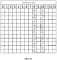
- a time division duplexing system further has three CSI-RS patterns of 8 ports shown in FIG. 10 , besides the 5 CSI-RS patterns of 8 ports shown in FIG. 1 . Therefore, besides the 10 CSI-RS pilot patterns, there also exist other 3 CSI-RS pilot patterns, and their specific configuration manners are consistent with the configuration manner in the FDD system, and thus will not be elaborated herein. It is important to note that a set of cells with the same mark (for example, " ⁇ " and "/”) in FIG. 10 represents a CSI-RS pattern of 8 ports (numbered to be 0, 1, 2, 3, 4, 5, 6 and 7 respectively and corresponding to the CSI-RS port serial numbers 0-7).
- the base station stores the CSI-RS pilot pattern (one of the multiple CSI-RS pilot patterns). For UE, it is necessary to distinguish new UE and conventional UE.
- the new UE may also store a CSI-RS pilot pattern consistent with the base station, and the conventional UE may consider the CSI-RS port serial numbers 0 ⁇ 3 and 8 ⁇ 11 (or 4 ⁇ 7 and 12 ⁇ 25) as CSI-RS port serial numbers 0 ⁇ 7, herein the new UE refers to UE with 16 ports, and the conventional UE refers to UE with 1, 2, 4 or 8 ports.
- the CSI-RS port serial numbers 0 ⁇ 15 in the CSI-RS pilot pattern shown in FIG. 6 may be changed into 15 ⁇ 30 shown in FIG. 11 , and the CSI-RS port serial numbers 0 ⁇ 7 corresponding to the group of 8 ports without any mark in the figure may be changed into 15 ⁇ 22.
- the CSI-RS port serial numbers 0 ⁇ 15 in the CSI-RS pilot patterns shown in FIG. 7 ⁇ FIG. 9 may also be changed into 15 ⁇ 30, of which a principle is similar to FIG. 6 and thus will not be elaborated herein.
- the CSI-RSs sent through the 16 CSI-RS ports are mapped to the RE set in the CSI-RS pilot pattern
- the RE set includes REs to which CSI-RSs of the two groups of 8 ports are mapped
- the first group of CSI-RS port serial numbers and second group of CSI-RS port serial numbers for the 16 CSI-RS ports are mapped to REs to which CSI-RSs of the first group of 8 ports in the two groups of 8 ports are mapped
- the third group of CSI-RS port serial numbers and the fourth group of CSI-RS port serial numbers are mapped to REs to which CSI-RSs of the second group of 8 ports in the two groups of 8 ports are mapped
- each of the first group of CSI-RS port serial numbers, the second group of CSI-RS port serial numbers, the third group of CSI-RS port serial numbers and the fourth group of CSI-RS port serial numbers includes 4 continuous CSI-RS port serial numbers, the first group of CSI-RS port serial numbers and the second group of CSI
- some embodiments of the disclosure provide a CSI-RS sending device, which is applied to a base station.
- the device includes:
- serial numbers of the 16 CSI-RS ports are sequentially 15, 16, 17, 18, 19, 20, 21, 22, 23, 24, 25, 26, 27, 28, 29 and 30.
- two continuous CSI-RS port serial numbers among the first group of CSI-RS port serial numbers are mapped to two REs located on a first subcarrier
- the other two continuous CSI-RS port serial numbers among the first group of CSI-RS port serial numbers are mapped to two REs located on a second subcarrier
- the first subcarrier and the second subcarrier are spaced by 5 subcarriers, and are two subcarriers among 4 subcarriers where the mapped REs for the CSI-RSs of the first group of 8 ports are located.
- two continuous CSI-RS port serial numbers among the second group of CSI-RS port serial numbers are mapped to two REs located on a third subcarrier
- the other two continuous CSI-RS port serial numbers among the second group of CSI-RS port serial numbers are mapped to two REs located on a fourth subcarrier
- the third subcarrier and the fourth subcarrier are spaced by 5 subcarriers, and are the other two subcarriers among the 4 subcarriers where the mapped REs for the CSI-RSs of the first group of 8 ports are located.
- two continuous CSI-RS port serial numbers among the third group of CSI-RS port serial numbers are mapped to two REs located on a fifth subcarrier
- the other two continuous CSI-RS port serial numbers among the third group of CSI-RS port serial numbers are mapped to two REs located on a sixth subcarrier
- the fifth subcarrier and the sixth subcarrier are spaced by 5 subcarriers, and are two subcarriers among 4 subcarriers where the mapped REs for the CSI-RSs of the second group of 8 ports are located.
- two continuous CSI-RS port serial numbers among the fourth group of CSI-RS port serial numbers are mapped to two REs located on a seventh subcarrier
- the other two continuous CSI-RS port serial numbers among the fourth group of CSI-RS port serial numbers are mapped to two REs located on an eighth subcarrier
- the seventh subcarrier and the eighth subcarrier are spaced by 5 subcarriers, and are the other two subcarriers among the 4 subcarriers where the mapped REs for the CSI-RSs of the second group of 8 ports are located.
- the first group of CSI-RS port serial numbers and the third group of CSI-RS port serial numbers form 8 continuous CSI-RS port serial numbers corresponding to 8 antennae or 8 radio frequency channels in a first polarization direction; and the second group of CSI-RS port serial numbers and the fourth group of CSI-RS port serial numbers form 8 continuous CSI-RS port serial numbers corresponding to 8 antennae or 8 radio frequency channels in a second polarization direction.
- 4 antennae or 4 radio frequency channels which correspond to the first group of CSI-RS port serial numbers and of which a polarization direction is the first polarization direction and 4 antennae or 4 radio frequency channels which correspond to the second group of CSI-RS port serial numbers and of which a polarization direction is the second polarization direction are at a first perpendicular location
- 4 antennae or 4 radio frequency channels which correspond to the fourth group of CSI-RS port serial numbers and of which a polarization direction is the second polarization direction are at a second perpendicular location.
- the base station maps the CSI-RSs sent through the 16 CSI-RS ports into the RE set in the CSI-RS pilot pattern
- the RE set includes the REs to which CSI-RSs of the two groups of 8 ports are mapped
- the first group of CSI-RS port serial numbers and second group of CSI-RS port serial numbers for the 16 CSI-RS ports are mapped to REs to which CSI-RSs of the first group of 8 ports in the two groups of 8 ports are mapped
- the third group of CSI-RS port serial numbers and the fourth group of CSI-RS port serial numbers are mapped to REs to which CSI-RSs of the second group of 8 ports in the two groups of 8 ports are mapped
- each of the first group of CSI-RS port serial numbers, the second group of CSI-RS port serial numbers, the third group of CSI-RS port serial numbers and the fourth group of CSI-RS port serial numbers includes 4 continuous CSI-RS port serial numbers, the first group of CSI-RS port serial numbers and the second group
- the CSI-RS sending device provided by some embodiments of the disclosure is a device applied to the CSI-RS sending method, that is, all the embodiments of the method are applied to the device, and the same or similar beneficial effects may be achieved.
- Some embodiments of the disclosure provide a base station, which includes the abovementioned CSI-RS sending device.
- the base station provided by some embodiments of the disclosure is a base station including the abovementioned CSI-RS sending device, that is, all the embodiments of the CSI-RS sending device are applied to the base station, and the same or similar beneficial effects may be achieved.
- some embodiments of the disclosure provide a CSI-RS sending method, which is applied to UE, the method including the following steps.
- CSI-RSs sent by a base station according to CSI-RS pattern information are received.
- the base station may notify the UE to receive the CSI-RSs sent by specific CSI-RS ports through the CSI-RS pattern information to enable the UE to accurately measure CSI, herein the operation that the base station notifies the UE to receive the CSI-RSs sent by the specific CSI-RS ports through the CSI-RS pattern information may be implemented by a conventional art, and thus will not be elaborated herein.
- CSI is measured on the basis of the received CSI-RSs.
- the measured CSI is sent to the base station.
- S1302 and S1303 may be implemented by adopting the conventional art, and thus will not be elaborated herein.
- the UE may receive the CSI-RSs sent by the base station according to the CSI-RS pattern information according to the CSI-RS pattern information received by itself, may measure the CSI on the basis of the received CSI-RSs, and finally sends the measured CSI to the base station, so that the problem of incapability of conventional UE in accurately performing CSI measurement when the base station sends CSI-RSs of 16 ports is solved, and effects of reducing a repeated overhead of the CSI-RSs, simultaneously making CSI measurement of the conventional UE more accurate and improving performance of a base station system are achieved.
- some embodiments of the disclosure provide a CSI-RS sending device, which is applied to UE, the device including:
- the UE may receive the CSI-RSs sent by the base station according to the CSI-RS pattern information according to the CSI-RS pattern information received by itself, may measure the CSI on the basis of the received CSI-RSs, and finally sends the measured CSI to the base station, so that the problem of incapability of conventional UE in accurately performing CSI measurement when the base station sends CSI-RSs of 16 ports is solved, and effects of reducing a repeated overhead of the CSI-RSs, simultaneously making CSI measurement of the conventional UE more accurate and improving performance of a base station system are achieved.
- the CSI-RS sending device provided by some embodiments of the disclosure is a device applied to the CSI-RS sending method, that is, all the embodiments of the method are applied to the device, and the same or similar beneficial effects may be achieved.
- Some embodiments of the disclosure provide UE, which includes the abovementioned CSI-RS sending device.
- the UE provided by some embodiments of the disclosure is UE including the abovementioned CSI-RS sending device, that is, all the embodiments of the CSI-RS sending device are applied to the UE, and the same or similar beneficial effects may be achieved.
Landscapes
- Engineering & Computer Science (AREA)
- Signal Processing (AREA)
- Computer Networks & Wireless Communication (AREA)
- Mobile Radio Communication Systems (AREA)
Abstract
Description
- The present application claims priority to Chinese Patent Application No.
201510741920.3, filed on November 4, 2015 - The disclosure relates to the field of wireless technologies, and particularly to a Channel State Information-Reference Signal (CSI-RS) sending method and device, a base station and User Equipment (UE).
- Communication systems in a related technology, for example, Long Term Evolution (LTE) and Worldwide Interoperability for Microwave Access (WiMax) and 802.11n, all adopt a 2nd-Dimensional (2D) Multiple-Input Multiple-Output (MIMO) technology, of which a basic principle is to improve transmission quality and increase a system capacity by a degree of freedom of a 2D space on a horizontal plane. Along with development of an antenna design architecture, for improving transmission efficiency of a mobile communication system and improving a user experience, it is necessary to fully explore a degree of freedom of a perpendicular space to extend the 2DMIMO technology to a 3rd-Dimensional (3D) MIMO technology and improve system performance by fully utilizing a degree of freedom of a 3D space.
- A 2DMIMO antenna architecture adopts multiple array elements in a perpendicular dimension, thereby obtaining a higher antenna gain. While each antenna array element in the perpendicular dimension adopts a fixed weight to ensure that a required beam pattern is obtained in the perpendicular dimension. Therefore, it is impossible for the 2DMIMO technology to implement beamforming in the perpendicular dimension.
- For fully utilizing a MIMO technology in the perpendicular dimension, 3DMIMO may control weighting factors of different antenna array elements in the perpendicular dimension to form different beams. The beams in the perpendicular dimension may be effectively distinguished, thereby providing multiple-user multiplexing in the perpendicular dimension and increasing a capacity. An LTE system supports a design of maximally 8 antennae, and 3D MIMO extends a channel number of an antenna, and supports a 3D antenna form with a channel number of 16, 32, 64, 128 and the like.
- In an existing standard, there are multiple CSI-RS patterns. For example, in a 2-port Frequency Division Duplexing (FDD) system, there are 20 patterns, and the specific CSI-RS pattern to be adopted is notified to UE through high-layer signaling. In each pattern, CSI-RSs are sent through each resource block of the whole bandwidth. Herein, as shown in
FIG. 1 , there are 5 patterns in an 8-port (numbered to be 0, 1, 2, 3, 4, 5, 6 and 7 respectively and corresponding to CSI-RSport serial numbers 15∼22) FDD system, herein a set of cells with the same mark (for example, "\" and "/") represents a pattern. - UE in the related technology feeds back Channel State Information (CSI) according to CSI-RS channel estimation. For an 8-antenna system in the related technology, a codebook set defined in a standard is optimally designed according to an 8-polarized-antenna form. 8 dual-polarized antennae in a horizontal dimension are considered. A numbering rule is usually as follows: as shown in
FIG. 2 , numbering is started from the same polarization direction, and then is performed in another polarization direction, herein the same sign is adopted to represent the same antenna polarization direction, figures below the antennae represent numbers of the antennae, and the numbers of the 8 antennae are sequentially 0, 1, 2, 3, 4, 5, 6 and 7. - During large-scale antenna 3D MIMO standardization, a CSI-RS pattern enhancement direction is mainly 16 ports, and 3D MIMO of a larger channel number is implemented by beamformed CSI-RSs, so that an excessive CSI-RS overhead is avoided. Design of a CSI-RS pattern of 16 ports is being discussed by existing standardization. At present, a 16-channel antenna form which is mainly considered is 4H2V (4 horizontal polarized antennae and 2 channels in a perpendicular direction). Considering a codebook design, a specific numbering rule is as follows: as shown in
FIG. 3 , numbering is started from the same polarization direction, and then is performed in another polarization direction, herein the same sign is adopted to represent the same antenna polarization direction, figures below antennae represent numbers of the antennae, and the numbers of the 16 antennae are sequentially 0, 1, 2, 3, 4, 5, 6, 7, 8, 9, 10, 11, 12, 13, 14 and 15. - At present, a main CSI-RS pattern design direction is combination of existing CSI-RSs of 8 ports into CSI-RSs of 16 ports. Under this situation, when a base station sends CSI-RSs of 16 ports, there exists the problem of how to feed back accurate CSI by conventional UE (UE with 8 ports).
- There are two solutions in the related technology, herein, in the first solution, the base station sends two sets of CSI-RSs, i.e., CSI-RSs of 16 ports+8ports (or 2 and 4 ports). This solution has the shortcoming that the base station sends the two sets of CSI-RSs, so that a Resource Element (RE) overhead is increased.
- In the second solution, the base station sends a set of CSI-RSs of 16 ports, notifies a CSI-RS pattern of 16 ports to new UE (UE with 16 ports) and notifies a CSI-RS pattern of 8 ports (or 2 and 4 ports) to conventional UE. Then, CSI-RSs read by the conventional UE are sent by antennae 0-7. However, an existing 8-antenna codebook is designed according to a dual-polarized antenna form. Therefore, this solution may not achieve relatively high compatibility with CSI measurement of the conventional UE.
- Embodiments of the disclosure are intended to provide a CSI-RS sending method and device, a base station and UE, which may reduce a repeated overhead of CSI-RSs, make CSI measurement of conventional UE more accurate and improve performance of a base station system.
- In order to achieve the purpose, the embodiments of the disclosure provide a CSI-RS sending method, which may be applied to a base station, the method including that:
- CSI-RSs are sent through 16 CSI-RS ports, herein the CSI-RSs may be mapped to an RE set in a CSI-RS pilot pattern, the RE set may include REs to which CSI-RSs of 2 groups of 8 ports are mapped, a first group of CSI-RS port serial numbers and second group of CSI-RS port serial numbers for the 16 CSI-RS ports may be mapped to REs to which CSI-RSs of the first group of 8 ports among the CSI-RSs of the two groups of 8 ports are mapped, and a third group of CSI-RS port serial numbers and fourth group of CSI-RS port serial numbers for the 16 CSI-RS ports may be mapped to REs to which CSI-RSs of the second group of 8 ports among the CSI-RSs of the two groups of 8 ports are mapped,
- herein each of the first group of CSI-RS port serial numbers, the second group of CSI-RS port serial numbers, the third group of CSI-RS port serial numbers and the fourth group of CSI-RS port serial numbers may include 4 continuous CSI-RS port serial numbers, the first group of CSI-RS port serial numbers and the second group of CSI-RS port serial numbers may be spaced by the third group of CSI-RS port serial numbers, and the third group of CSI-RS port serial numbers and the fourth group of CSI-RS port serial numbers may be spaced by the second group of CSI-RS port serial numbers; and
- CSI measured by UE on the basis of the CSI-RS is received.
- Herein, the serial numbers of the 16 CSI-RS ports may sequentially be 15, 16, 17, 18, 19, 20, 21, 22, 23, 24, 25, 26, 27, 28, 29 and 30.
- Herein, two continuous CSI-RS port serial numbers among the first group of CSI-RS port serial numbers may be mapped to two REs located on a first subcarrier, and the other two continuous CSI-RS port serial numbers among the first group of CSI-RS port serial numbers may be mapped to two REs located on a second subcarrier, herein the first subcarrier and the second subcarrier may be spaced by 5 subcarriers, and may be two subcarriers among 4 subcarriers where the mapped REs for the CSI-RSs of the first group of 8 ports are located.
- Herein, two continuous CSI-RS port serial numbers among the second group of CSI-RS port serial numbers may be mapped to two REs located on a third subcarrier, and the other two continuous CSI-RS port serial numbers among the second group of CSI-RS port serial numbers may be mapped to two REs located on a fourth subcarrier, herein the third subcarrier and the fourth subcarrier may be spaced by 5 subcarriers, and may be the other two subcarriers among the 4 subcarriers where the mapped REs for the CSI-RSs of the first group of 8 ports are located.
- Herein, two continuous CSI-RS port serial numbers among the third group of CSI-RS port serial numbers may be mapped to two REs located on a fifth subcarrier, and the other two continuous CSI-RS port serial numbers among the third group of CSI-RS port serial numbers may be mapped to two REs located on a sixth subcarrier, herein the fifth subcarrier and the sixth subcarrier may be spaced by 5 subcarriers, and may be two subcarriers among 4 subcarriers where the mapped REs for the CSI-RSs of the second group of 8 ports are located.
- Herein, two continuous CSI-RS port serial numbers among the fourth group of CSI-RS port serial numbers may be mapped to two REs located on a seventh subcarrier, and the other two continuous CSI-RS port serial numbers among the fourth group of CSI-RS port serial numbers may be mapped to two REs located on an eighth subcarrier, herein the seventh subcarrier and the eighth subcarrier may be spaced by 5 subcarriers, and may be the other two subcarriers among the 4 subcarriers where the mapped REs for the CSI-RSs of the second group of 8 ports are located.
- Herein, the first group of CSI-RS port serial numbers and the third group of CSI-RS port serial numbers may form 8 continuous CSI-RS port serial numbers corresponding to 8 antennae or 8 radio frequency channels in a first polarization direction; and the second group of CSI-RS port serial numbers and the fourth group of CSI-RS port serial numbers may form 8 continuous CSI-RS port serial numbers corresponding to 8 antennae or 8 radio frequency channels in a second polarization direction.
- Herein, 4 antennae or 4 radio frequency channels which correspond to the first group of CSI-RS port serial numbers and of which a polarization direction is the first polarization direction and 4 antennae or 4 radio frequency channels which correspond to the second group of CSI-RS port serial numbers and of which a polarization direction is the second polarization direction may be at a first perpendicular location, and 4 antennae or 4 radio frequency channels which correspond to the third group of CSI-RS port serial numbers and of which a polarization direction is the first polarization direction and 4 antennae or 4 radio frequency channels which correspond to the fourth group of CSI-RS port serial numbers and of which a polarization direction is the second polarization direction may be at a second perpendicular location.
- The embodiments of the disclosure further provide a CSI-RS sending device, which may be applied to a base station, the device including:
- a first sending module, arranged to send CSI-RSs through 16 CSI-RS ports, herein the CSI-RSs may be mapped to an RE set in a CSI-RS pilot pattern, the RE set may include REs to which CSI-RSs of 2 groups of 8 ports are mapped, a first group of CSI-RS port serial numbers and second group of CSI-RS port serial numbers for the 16 CSI-RS ports may be mapped to REs to which CSI-RSs of the first group of 8 ports among the CSI-RSs of the two groups of 8 ports are mapped, and a third group of CSI-RS port serial numbers and fourth group of CSI-RS port serial numbers for the 16 CSI-RS ports may be mapped to REs to which CSI-RSs of the second group of 8 ports among the CSI-RSs of the two groups of 8 ports are mapped,
- herein each of the first group of CSI-RS port serial numbers, the second group of CSI-RS port serial numbers, the third group of CSI-RS port serial numbers and the fourth group of CSI-RS port serial numbers may include 4 continuous CSI-RS port serial numbers, the first group of CSI-RS port serial numbers and the second group of CSI-RS port serial numbers may be spaced by the third group of CSI-RS port serial numbers, and the third group of CSI-RS port serial numbers and the fourth group of CSI-RS port serial numbers may be spaced by the second group of CSI-RS port serial numbers; and
- a first receiving module, arranged to receive CSI measured by UE on the basis of the CSI-RS.
- Herein, the serial numbers of the 16 CSI-RS ports may sequentially be 15, 16, 17, 18, 19, 20, 21, 22, 23, 24, 25, 26, 27, 28, 29 and 30.
- Herein, two continuous CSI-RS port serial numbers among the first group of CSI-RS port serial numbers may be mapped to two REs located on a first subcarrier, and the other two continuous CSI-RS port serial numbers among the first group of CSI-RS port serial numbers may be mapped to two REs located on a second subcarrier, herein the first subcarrier and the second subcarrier may be spaced by 5 subcarriers, and may be two subcarriers among 4 subcarriers where the mapped REs for the CSI-RSs of the first group of 8 ports are located.
- Herein, two continuous CSI-RS port serial numbers among the second group of CSI-RS port serial numbers may be mapped to two REs located on a third subcarrier, and the other two continuous CSI-RS port serial numbers among the second group of CSI-RS port serial numbers may be mapped to two REs located on a fourth subcarrier, herein the third subcarrier and the fourth subcarrier may be spaced by 5 subcarriers, and may be the other two subcarriers among the 4 subcarriers where the mapped REs for the CSI-RSs of the first group of 8 ports are located.
- Herein, two continuous CSI-RS port serial numbers among the third group of CSI-RS port serial numbers may be mapped to two REs located on a fifth subcarrier, and the other two continuous CSI-RS port serial numbers among the third group of CSI-RS port serial numbers may be mapped to two REs located on a sixth subcarrier, herein the fifth subcarrier and the sixth subcarrier may be spaced by 5 subcarriers, and may be two subcarriers among 4 subcarriers where the mapped REs for the CSI-RSs of the second group of 8 ports are located.
- Herein, two continuous CSI-RS port serial numbers among the fourth group of CSI-RS port serial numbers may be mapped to two REs located on a seventh subcarrier, and the other two continuous CSI-RS port serial numbers among the fourth group of CSI-RS port serial numbers may be mapped to two REs located on an eighth subcarrier, herein the seventh subcarrier and the eighth subcarrier may be spaced by 5 subcarriers, and may be the other two subcarriers among the 4 subcarriers where the mapped REs for the CSI-RSs of the second group of 8 ports are located.
- Herein, the first group of CSI-RS port serial numbers and the third group of CSI-RS port serial numbers may form 8 continuous CSI-RS port serial numbers corresponding to 8 antennae or 8 radio frequency channels in a first polarization direction; and the second group of CSI-RS port serial numbers and the fourth group of CSI-RS port serial numbers may form 8 continuous CSI-RS port serial numbers corresponding to 8 antennae or 8 radio frequency channels in a second polarization direction.
- Herein, 4 antennae or 4 radio frequency channels which correspond to the first group of CSI-RS port serial numbers and of which a polarization direction is the first polarization direction and 4 antennae or 4 radio frequency channels which correspond to the second group of CSI-RS port serial numbers and of which a polarization direction is the second polarization direction may be at a first perpendicular location, and 4 antennae or 4 radio frequency channels which correspond to the third group of CSI-RS port serial numbers and of which a polarization direction is the first polarization direction and 4 antennae or 4 radio frequency channels which correspond to the fourth group of CSI-RS port serial numbers and of which a polarization direction is the second polarization direction may be at a second perpendicular location.
- The embodiments of the disclosure further provide a base station, which may include the abovementioned CSI-RS sending device.
- The embodiments of the disclosure further provide a CSI-RS sending method, which may be applied to UE, the method including that:
- CSI-RSs sent by a base station according to CSI-RS pattern information are received;
- CSI is measured on the basis of the received CSI-RSs; and
- the measured CSI is sent to the base station.
- The embodiments of the disclosure further provide a CSI-RS sending device, which may be applied to UE, the device including:
- a second receiving module, arranged to receive CSI-RSs sent by a base station according to CSI-RS pattern information;
- a measurement module, arranged to measure CSI on the basis of the received CSI-RSs; and
- a second sending module, arranged to send the measured CSI to the base station.
- The embodiments of the disclosure further provide UE, which may include the abovementioned CSI-RS sending device.
- The solutions of the disclosure at least achieve the following beneficial effects.
- In the embodiments of the disclosure, the CSI-RSs sent through the 16 CSI-RS ports are mapped to the RE set in the CSI-RS pilot pattern, the RE set includes REs to which CSI-RSs of the two groups of 8 ports are mapped, the first group of CSI-RS port serial numbers and second group of CSI-RS port serial numbers for the 16 CSI-RS ports are mapped to REs to which CSI-RSs of the first group of 8 ports in the two groups of 8 ports are mapped, the third group of CSI-RS port serial numbers and the fourth group of CSI-RS port serial numbers are mapped to REs to which CSI-RSs of the second group of 8 ports in the two groups of 8 ports are mapped, each of the first group of CSI-RS port serial numbers, the second group of CSI-RS port serial numbers, the third group of CSI-RS port serial numbers and the fourth group of CSI-RS port serial numbers includes 4 continuous CSI-RS port serial numbers, the first group of CSI-RS port serial numbers and the second group of CSI-RS port serial numbers are spaced by the third group of CSI-RS port serial numbers, and the third group of CSI-RS port serial numbers and the fourth group of CSI-RS port serial numbers are spaced by the second group of CSI-RS port serial numbers, so that the problem of incapability of conventional UE in accurately performing CSI measurement when the base station sends CSI-RSs of 16 ports is solved, and effects of reducing a repeated overhead of the CSI-RSs, simultaneously making CSI measurement of the conventional UE more accurate and improving performance of a base station system are achieved.
-
-
FIG. 1 is a schematic diagram of a CSI-RS pattern of 8 ports according to the related technology. -
FIG. 2 is an antenna numbering diagram of 8 antennae according to the related technology. -
FIG. 3 is an antenna numbering diagram of 16 antennae according to the related technology. -
FIG. 4 is a flowchart of a CSI-RS sending method according to an embodiment of the disclosure. -
FIG. 5 is an antenna numbering diagram of 16 antennae according to an embodiment of the disclosure. -
FIG. 6 is a first schematic diagram of a CSI-RS pilot pattern according to an embodiment of the disclosure. -
FIG. 7 is a second schematic diagram of a CSI-RS pilot pattern according to an embodiment of the disclosure. -
FIG. 8 is a third schematic diagram of a CSI-RS pilot pattern according to an embodiment of the disclosure. -
FIG. 9 is a fourth schematic diagram of a CSI-RS pilot pattern according to an embodiment of the disclosure. -
FIG. 10 is a diagram of a CSI-RS pattern of 8 ports in a time division duplexing system according to an embodiment of the disclosure. -
FIG. 11 is a fifth schematic diagram of a CSI-RS pilot pattern according to an embodiment of the disclosure. -
FIG. 12 is a structure diagram of a CSI-RS sending device according to an embodiment of the disclosure. -
FIG. 13 is a flowchart of a CSI-RS sending method according to at least some embodiments of the disclosure. -
FIG. 14 is a structure diagram of a CSI-RS sending device according to at least some embodiments of the disclosure. - Exemplary embodiments of the disclosure will be described below with reference to the drawings in more detail. Although the exemplary embodiments of the disclosure are shown in the drawings, it should be understood that the disclosure may be implemented in various forms and should not be limited by the embodiments elaborated herein. On the contrary, these embodiments are provided to make the disclosure understood more thoroughly and completely deliver the scope of the disclosure to those skilled in the art.
- As shown in
FIG. 4 , an embodiment of the disclosure provides a CSI-RS sending method, which is applied to a base station, herein the method includes the following steps. - In S401, CSI-RSs are sent through 16 CSI-RS ports.
- In an embodiment of the disclosure, the base station may send the CSI-RSs of the 16 ports to UE.
- In S402, CSI measured by UE on the basis of the CSI-RS is received.
- In an embodiment of the disclosure, the CSI-RSs are mapped to one or more RE sets in a CSI-RS pilot pattern, herein each RE set includes REs to which CSI-RSs of 2 groups of 8 ports are mapped, a first group of CSI-RS port serial numbers and second group of CSI-RS port serial numbers for the 16 CSI-RS ports are mapped to REs to which CSI-RSs of the first group of 8 ports among the CSI-RSs of the two groups of 8 ports are mapped, and a third group of CSI-RS port serial numbers and fourth group of CSI-RS port serial numbers for the 16 CSI-RS ports are mapped to REs to which CSI-RSs of the second group of 8 ports among the CSI-RSs of the two groups of 8 ports are mapped, herein each of the first group of CSI-RS port serial numbers, the second group of CSI-RS port serial numbers, the third group of CSI-RS port serial numbers and the fourth group of CSI-RS port serial numbers includes 4 continuous CSI-RS port serial numbers, the first group of CSI-RS port serial numbers and the second group of CSI-RS port serial numbers are spaced by the third group of CSI-RS port serial numbers, and the third group of CSI-RS port serial numbers and the fourth group of CSI-RS port serial numbers are spaced by the second group of CSI-RS port serial numbers.
- It is important to note that, in an embodiment of the disclosure, an arrangement and numbering manner of 16 antennae corresponding to the 16 CSI-RS ports may be shown in
FIG. 3 and may also be shown inFIG. 5 . Of course, a numbering rule of the 16 antennae inFIG. 5 is as follows: numbering is started from the same polarization direction, and then is performed in another polarization direction, herein the same sign (for example, "/") is adopted to represent the same antenna polarization direction, figures below the antennae are numbers of the antennae, and the number of each antenna corresponds to a CSI-RS port serial number. Therefore, when the numbers of the 16 antennae inFIG. 5 are 0, 1, 2, 3, 4, 5, 6, 7, 8, 9, 10, 11, 12, 13, 14 and 15 respectively, the 16 corresponding CSI-RS port serial numbers are 0, 1, 2, 3, 4, 5, 6, 7, 8, 9, 10, 11, 12, 13, 14 and 15 respectively. It is important to note that, in an embodiment of the disclosure, specific figures of the numbers of the antennae and the CSI-RS port serial numbers are not limited. Specifically, the 16 CSI-RS port serial numbers may sequentially be X+0, X+1, X+2, X+3, X+4, X+5, X+6, X+7, X+8, X+9, X+10, X+11, X+12, X+13, X+14 and X+15, herein X is a natural number. Typically, X is 15, that is, the 16 CSI-RS port serial numbers are sequentially 15, 16, 17, 18, 19, 20, 21, 22, 23, 24, 25, 26, 27, 28, 29 and 30. - It is important to note that the first group of CSI-RS port serial numbers and the third group of CSI-RS port serial numbers form 8 continuous CSI-RS port serial numbers corresponding to 8 antennae (for example, 8 antennae numbered to be 0, 1, 2, 3, 4, 5, 6 and 7 in
FIG. 5 ) or radio frequency channels in a first polarization direction; and the second group of CSI-RS port serial numbers and the fourth group of CSI-RS port serial numbers form 8 continuous CSI-RS port serial numbers corresponding to 8 antennae (for example, 8 antennae numbered to be 8, 9, 10, 11, 12, 13, 14 and 15 inFIG. 5 ) or radio frequency channels in a second polarization direction. Furthermore, 4 antennae (for example, the 4 antennae numbered to be 0, 1, 2 and 3 inFIG. 5 ) or radio frequency channels which correspond to the first group of CSI-RS port serial numbers and of which a polarization direction is the first polarization direction and 4 antennae (for example, the 4 antennae numbered to be 8, 9, 10 and 11 inFIG. 5 ) or radio frequency channels which correspond to the second group of CSI-RS port serial numbers and of which a polarization direction is the second polarization direction are at a first perpendicular location, and 4 antennae (for example, the 4 antennae numbered to be 4, 5, 6 and 7 inFIG. 5 ) or radio frequency channels which correspond to the third group of CSI-RS port serial numbers and of which a polarization direction is the first polarization direction and 4 antennae (for example, the 4 antennae numbered to be 12, 13, 14 and 15 inFIG. 5 ) or radio frequency channels which correspond to the fourth group of CSI-RS port serial numbers and of which a polarization direction is the second polarization direction are at a second perpendicular location. - In an embodiment of the disclosure, two continuous CSI-RS port serial numbers (CSI-RS port serial numbers corresponding to the antennae numbered to be 0 and 1 in
FIG. 5 ) in the first group of CSI-RS port serial numbers (CSI-RS port serial numbers corresponding to the antennae numbered to be 0, 1, 2 and 3 inFIG. 5 ) are mapped to two REs located on a first subcarrier, and the other two continuous CSI-RS port serial numbers (CSI-RS port serial numbers corresponding to the antennae numbered to be 2 and 3 inFIG. 5 ) in the first group of CSI-RS port serial numbers are mapped to two REs located on a second subcarrier, herein the first subcarrier and the second subcarrier are two subcarriers among 4 subcarriers where the mapped REs for the CSI-RSs of the first group of 8 ports are located. Furthermore, two continuous CSI-RS port serial numbers (CSI-RS port serial numbers corresponding to the antennae numbered to be 8 and 9 inFIG. 5 ) in the second group of CSI-RS port serial numbers (CSI-RS port serial numbers corresponding to the antennae numbered to be 8, 9, 10 and 11 inFIG. 5 ) are mapped to two REs located on a third subcarrier, and the other two continuous CSI-RS port serial numbers (CSI-RS port serial numbers corresponding to the antennae numbered to be 10 and 11 inFIG. 5 ) in the second group of CSI-RS port serial numbers are mapped to two REs located on a fourth subcarrier, herein the third subcarrier and the fourth subcarrier are the other two subcarriers among the 4 subcarriers where the mapped REs for the CSI-RSs of the first group of 8 ports are located. - Similarly, two continuous CSI-RS port serial numbers (CSI-RS port serial numbers corresponding to the antennae numbered to be 4 and 5 in
FIG. 5 ) in the third group of CSI-RS port serial numbers (CSI-RS port serial numbers corresponding to the antennae numbered to be 4, 5, 6 and 7 inFIG. 5 ) are mapped to two REs located on a fifth subcarrier, and the other two continuous CSI-RS port serial numbers (CSI-RS port serial numbers corresponding to the antennae numbered to be 6 and 7 inFIG. 5 ) in the third group of CSI-RS port serial numbers are mapped to two REs located on a sixth subcarrier, herein the fifth subcarrier and the sixth subcarrier are two subcarriers among 4 subcarriers where the mapped REs for the CSI-RSs of the second group of 8 ports are located. Furthermore, two continuous CSI-RS port serial numbers (CSI-RS port serial numbers corresponding to the antennae numbered to be 12 and 13 inFIG. 5 ) in the fourth group of CSI-RS port serial numbers (CSI-RS port serial numbers corresponding to the antennae numbered to be 12, 13, 14 and 15 inFIG. 5 ) are mapped to two REs located on a seventh subcarrier, and the other two continuous CSI-RS port serial numbers (CSI-RS port serial numbers corresponding to the antennae numbered to be 14 and 15 inFIG. 5 ) in the fourth group of CSI-RS port serial numbers are mapped to two REs located on an eighth subcarrier, herein the seventh subcarrier and the eighth subcarrier are the other two subcarriers among the 4 subcarriers where the mapped REs for the CSI-RSs of the second group of 8 ports are located. - In an embodiment of the disclosure, there are multiple CSI-RS pilot patterns, herein, when X is 0, for an FDD system, any two patterns (i.e., a CSI-RS pattern of the first group of 8 ports and a CSI-RS pattern of the second group of 8 ports respectively) may be selected from CSI-RS patterns of 8 ports shown in
FIG. 1 to be combined into a CSI-RS pattern of 16 ports. It is important to note that mapping locations of the 16 CSI-RS port serial numbers are required to be changed after combination. Specifically, numbers 0-7 in the CSI-RS pattern of the first group of 8 ports may be changed into 0-3 and 8-11 (or 4-7 and 12-15), and numbers 0-7 in the CSI-RS pattern of the second group of 8 ports may be sequentially changed into 4∼7 and 12∼15 (or 0∼3 and 8∼11). Since there exist 5 CSI-RS patterns inFIG. 1 , there should correspondingly exist 10 (i.e., C(5,2)) CSI-RS pilot patterns (as shown inFIG. 6∼FIG. 9 , any two patterns are selected from the CSI-RS patterns of the 8 ports shown inFIG. 1 to form 4 CSI-RS pilot patterns of the CSI-RSs of the 16 ports) in the FDD system, and there may exist mapping locations of two groups of 16 ports in each CSI-RS pilot pattern. Under this situation, when the base station sends the CSI-RSs, the CSI-RSs may be mapped to at least one group of 16 ports (i.e., the RE set) in the CSI-RS pilot pattern. It is important to note that, for conveniently and clearly representing the CSI-RS pattern of the 16 ports, a set of cells with the same mark (for example, "\" and "/") in each figure represents mapping locations of a group of 16 ports, and a group of 8 ports (numbered to be 0, 1, 2, 3, 4, 5, 6 and 7 respectively and corresponding to the CSI-RS portserial numbers 0∼7) without any mark in the figure are mainly intended to make it convenient for the base station to send the CSI-RSs of the 8 ports under a certain circumstance. It is important to note thatfigures 0∼15 inFIG. 6∼FIG. 9 sequentially correspond to the 16 CSI-RS portserial numbers 0∼15. - A time division duplexing system further has three CSI-RS patterns of 8 ports shown in
FIG. 10 , besides the 5 CSI-RS patterns of 8 ports shown inFIG. 1 . Therefore, besides the 10 CSI-RS pilot patterns, there also exist other 3 CSI-RS pilot patterns, and their specific configuration manners are consistent with the configuration manner in the FDD system, and thus will not be elaborated herein. It is important to note that a set of cells with the same mark (for example, "\" and "/") inFIG. 10 represents a CSI-RS pattern of 8 ports (numbered to be 0, 1, 2, 3, 4, 5, 6 and 7 respectively and corresponding to the CSI-RS port serial numbers 0-7). - In an embodiment of the disclosure, the base station stores the CSI-RS pilot pattern (one of the multiple CSI-RS pilot patterns). For UE, it is necessary to distinguish new UE and conventional UE. The new UE may also store a CSI-RS pilot pattern consistent with the base station, and the conventional UE may consider the CSI-RS port
serial numbers 0∼3 and 8∼11 (or 4∼7 and 12∼25) as CSI-RS portserial numbers 0∼7, herein the new UE refers to UE with 16 ports, and the conventional UE refers to UE with 1, 2, 4 or 8 ports. - It is important to further note that, in an embodiment of the disclosure, when X is 15, the CSI-RS port
serial numbers 0∼15 in the CSI-RS pilot pattern shown inFIG. 6 may be changed into 15∼30 shown inFIG. 11 , and the CSI-RS portserial numbers 0∼7 corresponding to the group of 8 ports without any mark in the figure may be changed into 15∼22. Of course, the CSI-RS portserial numbers 0∼15 in the CSI-RS pilot patterns shown inFIG. 7∼FIG. 9 may also be changed into 15∼30, of which a principle is similar toFIG. 6 and thus will not be elaborated herein. - In an embodiment of the disclosure, the CSI-RSs sent through the 16 CSI-RS ports are mapped to the RE set in the CSI-RS pilot pattern, the RE set includes REs to which CSI-RSs of the two groups of 8 ports are mapped, the first group of CSI-RS port serial numbers and second group of CSI-RS port serial numbers for the 16 CSI-RS ports are mapped to REs to which CSI-RSs of the first group of 8 ports in the two groups of 8 ports are mapped, the third group of CSI-RS port serial numbers and the fourth group of CSI-RS port serial numbers are mapped to REs to which CSI-RSs of the second group of 8 ports in the two groups of 8 ports are mapped, each of the first group of CSI-RS port serial numbers, the second group of CSI-RS port serial numbers, the third group of CSI-RS port serial numbers and the fourth group of CSI-RS port serial numbers includes 4 continuous CSI-RS port serial numbers, the first group of CSI-RS port serial numbers and the second group of CSI-RS port serial numbers are spaced by the third group of CSI-RS port serial numbers, and the third group of CSI-RS port serial numbers and the fourth group of CSI-RS port serial numbers are spaced by the second group of CSI-RS port serial numbers, so that the problem of incapability of conventional UE in accurately performing CSI measurement when the base station sends CSI-RSs of 16 ports is solved, and effects of reducing a repeated overhead of the CSI-RSs, simultaneously making CSI measurement of the conventional UE more accurate and improving performance of a base station system are achieved.
- As shown in
FIG. 12 , some embodiments of the disclosure provide a CSI-RS sending device, which is applied to a base station. The device includes: - a
first sending module 1201, arranged to send CSI-RSs through 16 CSI-RS ports, herein the CSI-RSs are mapped to an RE set in a CSI-RS pilot pattern, the RE set includes REs to which CSI-RSs of 2 groups of 8 ports are mapped, a first group of CSI-RS port serial numbers and second group of CSI-RS port serial numbers for the 16 CSI-RS ports are mapped to REs to which CSI-RSs of the first group of 8 ports among the CSI-RSs of the two groups of 8 ports are mapped, and a third group of CSI-RS port serial numbers and fourth group of CSI-RS port serial numbers for the 16 CSI-RS ports are mapped to REs to which CSI-RSs of the second group of 8 ports among the CSI-RSs of the two groups of 8 ports are mapped, - herein each of the first group of CSI-RS port serial numbers, the second group of CSI-RS port serial numbers, the third group of CSI-RS port serial numbers and the fourth group of CSI-RS port serial numbers includes 4 continuous CSI-RS port serial numbers, the first group of CSI-RS port serial numbers and the second group of CSI-RS port serial numbers are spaced by the third group of CSI-RS port serial numbers, and the third group of CSI-RS port serial numbers and the fourth group of CSI-RS port serial numbers are spaced by the second group of CSI-RS port serial numbers; and
- a
first receiving module 1202, arranged to receive CSI measured by UE on the basis of the CSI-RS. - Herein, the serial numbers of the 16 CSI-RS ports are sequentially 15, 16, 17, 18, 19, 20, 21, 22, 23, 24, 25, 26, 27, 28, 29 and 30.
- Herein, two continuous CSI-RS port serial numbers among the first group of CSI-RS port serial numbers are mapped to two REs located on a first subcarrier, and the other two continuous CSI-RS port serial numbers among the first group of CSI-RS port serial numbers are mapped to two REs located on a second subcarrier, herein the first subcarrier and the second subcarrier are spaced by 5 subcarriers, and are two subcarriers among 4 subcarriers where the mapped REs for the CSI-RSs of the first group of 8 ports are located.
- Herein, two continuous CSI-RS port serial numbers among the second group of CSI-RS port serial numbers are mapped to two REs located on a third subcarrier, and the other two continuous CSI-RS port serial numbers among the second group of CSI-RS port serial numbers are mapped to two REs located on a fourth subcarrier, herein the third subcarrier and the fourth subcarrier are spaced by 5 subcarriers, and are the other two subcarriers among the 4 subcarriers where the mapped REs for the CSI-RSs of the first group of 8 ports are located.
- Herein, two continuous CSI-RS port serial numbers among the third group of CSI-RS port serial numbers are mapped to two REs located on a fifth subcarrier, and the other two continuous CSI-RS port serial numbers among the third group of CSI-RS port serial numbers are mapped to two REs located on a sixth subcarrier, herein the fifth subcarrier and the sixth subcarrier are spaced by 5 subcarriers, and are two subcarriers among 4 subcarriers where the mapped REs for the CSI-RSs of the second group of 8 ports are located.
- Herein, two continuous CSI-RS port serial numbers among the fourth group of CSI-RS port serial numbers are mapped to two REs located on a seventh subcarrier, and the other two continuous CSI-RS port serial numbers among the fourth group of CSI-RS port serial numbers are mapped to two REs located on an eighth subcarrier, herein the seventh subcarrier and the eighth subcarrier are spaced by 5 subcarriers, and are the other two subcarriers among the 4 subcarriers where the mapped REs for the CSI-RSs of the second group of 8 ports are located.
- Herein, the first group of CSI-RS port serial numbers and the third group of CSI-RS port serial numbers form 8 continuous CSI-RS port serial numbers corresponding to 8 antennae or 8 radio frequency channels in a first polarization direction; and the second group of CSI-RS port serial numbers and the fourth group of CSI-RS port serial numbers form 8 continuous CSI-RS port serial numbers corresponding to 8 antennae or 8 radio frequency channels in a second polarization direction.
- Herein, 4 antennae or 4 radio frequency channels which correspond to the first group of CSI-RS port serial numbers and of which a polarization direction is the first polarization direction and 4 antennae or 4 radio frequency channels which correspond to the second group of CSI-RS port serial numbers and of which a polarization direction is the second polarization direction are at a first perpendicular location, and 4 antennae or 4 radio frequency channels which correspond to the third group of CSI-RS port serial numbers and of which a polarization direction is the first polarization direction and 4 antennae or 4 radio frequency channels which correspond to the fourth group of CSI-RS port serial numbers and of which a polarization direction is the second polarization direction are at a second perpendicular location.
- In some embodiments of the disclosure, the base station maps the CSI-RSs sent through the 16 CSI-RS ports into the RE set in the CSI-RS pilot pattern, the RE set includes the REs to which CSI-RSs of the two groups of 8 ports are mapped, the first group of CSI-RS port serial numbers and second group of CSI-RS port serial numbers for the 16 CSI-RS ports are mapped to REs to which CSI-RSs of the first group of 8 ports in the two groups of 8 ports are mapped, the third group of CSI-RS port serial numbers and the fourth group of CSI-RS port serial numbers are mapped to REs to which CSI-RSs of the second group of 8 ports in the two groups of 8 ports are mapped, each of the first group of CSI-RS port serial numbers, the second group of CSI-RS port serial numbers, the third group of CSI-RS port serial numbers and the fourth group of CSI-RS port serial numbers includes 4 continuous CSI-RS port serial numbers, the first group of CSI-RS port serial numbers and the second group of CSI-RS port serial numbers are spaced by the third group of CSI-RS port serial numbers, and the third group of CSI-RS port serial numbers and the fourth group of CSI-RS port serial numbers are spaced by the second group of CSI-RS port serial numbers, so that the problem of incapability of conventional UE in accurately performing CSI measurement when the base station sends CSI-RSs of 16 ports is solved, and effects of reducing a repeated overhead of the CSI-RSs, simultaneously making CSI measurement of the conventional UE more accurate and improving performance of a base station system are achieved.
- It is important to note that the CSI-RS sending device provided by some embodiments of the disclosure is a device applied to the CSI-RS sending method, that is, all the embodiments of the method are applied to the device, and the same or similar beneficial effects may be achieved.
- Some embodiments of the disclosure provide a base station, which includes the abovementioned CSI-RS sending device.
- It is important to note that the base station provided by some embodiments of the disclosure is a base station including the abovementioned CSI-RS sending device, that is, all the embodiments of the CSI-RS sending device are applied to the base station, and the same or similar beneficial effects may be achieved.
- As shown in
FIG. 13 , some embodiments of the disclosure provide a CSI-RS sending method, which is applied to UE, the method including the following steps. - In S1301, CSI-RSs sent by a base station according to CSI-RS pattern information are received.
- In some embodiments of the disclosure, before S1301 is executed, the base station may notify the UE to receive the CSI-RSs sent by specific CSI-RS ports through the CSI-RS pattern information to enable the UE to accurately measure CSI, herein the operation that the base station notifies the UE to receive the CSI-RSs sent by the specific CSI-RS ports through the CSI-RS pattern information may be implemented by a conventional art, and thus will not be elaborated herein.
- In 1302, CSI is measured on the basis of the received CSI-RSs.
- In 1303, the measured CSI is sent to the base station.
- In some embodiments of the disclosure, S1302 and S1303 may be implemented by adopting the conventional art, and thus will not be elaborated herein.
- In some embodiments of the disclosure, the UE (new UE or conventional UE) may receive the CSI-RSs sent by the base station according to the CSI-RS pattern information according to the CSI-RS pattern information received by itself, may measure the CSI on the basis of the received CSI-RSs, and finally sends the measured CSI to the base station, so that the problem of incapability of conventional UE in accurately performing CSI measurement when the base station sends CSI-RSs of 16 ports is solved, and effects of reducing a repeated overhead of the CSI-RSs, simultaneously making CSI measurement of the conventional UE more accurate and improving performance of a base station system are achieved.
- As shown in
FIG. 14 , some embodiments of the disclosure provide a CSI-RS sending device, which is applied to UE, the device including: - a
second receiving module 1401, arranged to receive CSI-RSs sent by a base station according to CSI-RS pattern information; - a
measurement module 1402, arranged to measure CSI on the basis of the received CSI-RSs; and - a
second sending module 1403, arranged to send the measured CSI to the base station. - In some embodiments of the disclosure, the UE (new UE or conventional UE) may receive the CSI-RSs sent by the base station according to the CSI-RS pattern information according to the CSI-RS pattern information received by itself, may measure the CSI on the basis of the received CSI-RSs, and finally sends the measured CSI to the base station, so that the problem of incapability of conventional UE in accurately performing CSI measurement when the base station sends CSI-RSs of 16 ports is solved, and effects of reducing a repeated overhead of the CSI-RSs, simultaneously making CSI measurement of the conventional UE more accurate and improving performance of a base station system are achieved.
- It is important to note that the CSI-RS sending device provided by some embodiments of the disclosure is a device applied to the CSI-RS sending method, that is, all the embodiments of the method are applied to the device, and the same or similar beneficial effects may be achieved.
- Some embodiments of the disclosure provide UE, which includes the abovementioned CSI-RS sending device.
- It is important to note that the UE provided by some embodiments of the disclosure is UE including the abovementioned CSI-RS sending device, that is, all the embodiments of the CSI-RS sending device are applied to the UE, and the same or similar beneficial effects may be achieved.
- The above is the preferred implementation mode of the disclosure. It should be pointed out that those of ordinary skilled in the art may further make a plurality of improvements and embellishments without departing from the principle of the disclosure and these improvements and embellishments shall also fall within the scope of protection of the disclosure.
Claims (20)
- A Channel State Information-Reference Signal (CSI-RS) sending method, applied to a base station, the method comprising:sending CSI-RSs through 16 CSI-RS ports, herein the CSI-RSs are mapped to a Resource Element (RE) set in a CSI-RS pilot pattern, the RE set comprising REs to which CSI-RSs of 2 groups of 8 ports are mapped, a first group of CSI-RS port serial numbers and second group of CSI-RS port serial numbers for the 16 CSI-RS ports are mapped to REs to which CSI-RSs of the first group of 8 ports among the CSI-RSs of the two groups of 8 ports are mapped, and a third group of CSI-RS port serial numbers and fourth group of CSI-RS port serial numbers for the 16 CSI-RS ports are mapped to REs to which CSI-RSs of the second group of 8 ports among the CSI-RSs of the two groups of 8 ports are mapped,herein each of the first group of CSI-RS port serial numbers, the second group of CSI-RS port serial numbers, the third group of CSI-RS port serial numbers and the fourth group of CSI-RS port serial numbers comprises 4 continuous CSI-RS port serial numbers, the first group of CSI-RS port serial numbers and the second group of CSI-RS port serial numbers are spaced by the third group of CSI-RS port serial numbers, and the third group of CSI-RS port serial numbers and the fourth group of CSI-RS port serial numbers are spaced by the second group of CSI-RS port serial numbers; andreceiving Channel State Information (CSI) measured by User Equipment (UE) on the basis of the CSI-RSs.
- The method according to claim 1, wherein serial numbers of the 16 CSI-RS ports are sequentially 15, 16, 17, 18, 19, 20, 21, 22, 23, 24, 25, 26, 27, 28, 29 and 30.
- The method according to claim 1, wherein two continuous CSI-RS port serial numbers among the first group of CSI-RS port serial numbers are mapped to two REs located on a first subcarrier, and the other two continuous CSI-RS port serial numbers among the first group of CSI-RS port serial numbers are mapped to two REs located on a second subcarrier, wherein the first subcarrier and the second subcarrier are spaced by 5 subcarriers, and are two subcarriers among 4 subcarriers where the mapped REs for the CSI-RSs of the first group of 8 ports are located.
- The method according to claim 3, wherein two continuous CSI-RS port serial numbers among the second group of CSI-RS port serial numbers are mapped to two REs located on a third subcarrier, and the other two continuous CSI-RS port serial numbers among the second group of CSI-RS port serial numbers are mapped to two REs located on a fourth subcarrier, wherein the third subcarrier and the fourth subcarrier are spaced by 5 subcarriers, and are the other two subcarriers among the 4 subcarriers where the mapped REs for the CSI-RSs of the first group of 8 ports are located.
- The method according to claim 1, wherein two continuous CSI-RS port serial numbers among the third group of CSI-RS port serial numbers are mapped to two REs located on a fifth subcarrier, and the other two continuous CSI-RS port serial numbers among the third group of CSI-RS port serial numbers are mapped to two REs located on a sixth subcarrier, wherein the fifth subcarrier and the sixth subcarrier are spaced by 5 subcarriers, and are two subcarriers among 4 subcarriers where the mapped REs for the CSI-RSs of the second group of 8 ports are located.
- The method according to claim 5, wherein two continuous CSI-RS port serial numbers among the fourth group of CSI-RS port serial numbers are mapped to two REs located on a seventh subcarrier, and the other two continuous CSI-RS port serial numbers among the fourth group of CSI-RS port serial numbers are mapped to two REs located on an eighth subcarrier, wherein the seventh subcarrier and the eighth subcarrier are spaced by 5 subcarriers, and are the other two subcarriers among the 4 subcarriers where the mapped REs for the CSI-RSs of the second group of 8 ports are located.
- The method according to claim 1, wherein the first group of CSI-RS port serial numbers and the third group of CSI-RS port serial numbers form 8 continuous CSI-RS port serial numbers corresponding to 8 antennae or 8 radio frequency channels in a first polarization direction; and the second group of CSI-RS port serial numbers and the fourth group of CSI-RS port serial numbers form 8 continuous CSI-RS port serial numbers corresponding to 8 antennae or 8 radio frequency channels in a second polarization direction.
- The method according to claim 7, wherein 4 antennae or 4 radio frequency channels which correspond to the first group of CSI-RS port serial numbers and of which a polarization direction is the first polarization direction and 4 antennae or 4 radio frequency channels which correspond to the second group of CSI-RS port serial numbers and of which a polarization direction is the second polarization direction are at a first perpendicular location, and 4 antennae or 4 radio frequency channels which correspond to the third group of CSI-RS port serial numbers and of which a polarization direction is the first polarization direction and 4 antennae or 4 radio frequency channels which correspond to the fourth group of CSI-RS port serial numbers and of which a polarization direction is the second polarization direction are at a second perpendicular location.
- A Channel State Information-Reference Signal (CSI-RS) sending device, applied to a base station, wherein the device comprises:a first sending module, arranged to send CSI-RSs through 16 CSI-RS ports, wherein the CSI-RSs are mapped to a Resource Element (RE) set in a CSI-RS pilot pattern, the RE set comprises REs to which CSI-RSs of 2 groups of 8 ports are mapped, a first group of CSI-RS port serial numbers and second group of CSI-RS port serial numbers for the 16 CSI-RS ports are mapped to REs to which CSI-RSs of the first group of 8 ports among the CSI-RSs of the two groups of 8 ports are mapped, and a third group of CSI-RS port serial numbers and fourth group of CSI-RS port serial numbers for the 16 CSI-RS ports are mapped to REs to which CSI-RSs of the second group of 8 ports among the CSI-RSs of the two groups of 8 ports are mapped,wherein each of the first group of CSI-RS port serial numbers, the second group of CSI-RS port serial numbers, the third group of CSI-RS port serial numbers and the fourth group of CSI-RS port serial numbers comprises 4 continuous CSI-RS port serial numbers, the first group of CSI-RS port serial numbers and the second group of CSI-RS port serial numbers are spaced by the third group of CSI-RS port serial numbers, and the third group of CSI-RS port serial numbers and the fourth group of CSI-RS port serial numbers are spaced by the second group of CSI-RS port serial numbers; anda first receiving module, arranged to receive Channel State Information (CSI) measured by User Equipment (UE) on the basis of the CSI-RS.
- The device according to claim 9, wherein the serial numbers of the 16 CSI-RS ports are sequentially 15, 16, 17, 18, 19, 20, 21, 22, 23, 24, 25, 26, 27, 28, 29 and 30.
- The device according to claim 9, wherein two continuous CSI-RS port serial numbers among the first group of CSI-RS port serial numbers are mapped to two REs located on a first subcarrier, and the other two continuous CSI-RS port serial numbers among the first group of CSI-RS port serial numbers are mapped to two REs located on a second subcarrier, wherein the first subcarrier and the second subcarrier are spaced by 5 subcarriers, and are two subcarriers among 4 subcarriers where the mapped REs for the CSI-RSs of the first group of 8 ports are located.
- The device according to claim 11, wherein two continuous CSI-RS port serial numbers among the second group of CSI-RS port serial numbers are mapped to two REs located on a third subcarrier, and the other two continuous CSI-RS port serial numbers among the second group of CSI-RS port serial numbers are mapped to two REs located on a fourth subcarrier, wherein the third subcarrier and the fourth subcarrier are spaced by 5 subcarriers, and are the other two subcarriers among the 4 subcarriers where the mapped REs for the CSI-RSs of the first group of 8 ports are located.
- The device according to claim 9, wherein two continuous CSI-RS port serial numbers among the third group of CSI-RS port serial numbers are mapped to two REs located on a fifth subcarrier, and the other two continuous CSI-RS port serial numbers among the third group of CSI-RS port serial numbers are mapped to two REs located on a sixth subcarrier, wherein the fifth subcarrier and the sixth subcarrier are spaced by 5 subcarriers, and are two subcarriers among 4 subcarriers where the mapped REs for the CSI-RSs of the second group of 8 ports are located.
- The device according to claim 13, wherein two continuous CSI-RS port serial numbers among the fourth group of CSI-RS port serial numbers are mapped to two REs located on a seventh subcarrier, and the other two continuous CSI-RS port serial numbers among the fourth group of CSI-RS port serial numbers are mapped to two REs located on an eighth subcarrier, wherein the seventh subcarrier and the eighth subcarrier are spaced by 5 subcarriers, and are the other two subcarriers among the 4 subcarriers where the mapped REs for the CSI-RSs of the second group of 8 ports are located.
- The device according to claim 9, wherein the first group of CSI-RS port serial numbers and the third group of CSI-RS port serial numbers form 8 continuous CSI-RS port serial numbers corresponding to 8 antennae or 8 radio frequency channels in a first polarization direction; and the second group of CSI-RS port serial numbers and the fourth group of CSI-RS port serial numbers form 8 continuous CSI-RS port serial numbers corresponding to 8 antennae or 8 radio frequency channels in a second polarization direction.
- The device according to claim 15, wherein 4 antennae or 4 radio frequency channels which correspond to the first group of CSI-RS port serial numbers and of which a polarization direction is the first polarization direction and 4 antennae or 4 radio frequency channels which correspond to the second group of CSI-RS port serial numbers and of which a polarization direction is the second polarization direction are at a first perpendicular location, and 4 antennae or 4 radio frequency channels which correspond to the third group of CSI-RS port serial numbers and of which a polarization direction is the first polarization direction and 4 antennae or 4 radio frequency channels which correspond to the fourth group of CSI-RS port serial numbers and of which a polarization direction is the second polarization direction are at a second perpendicular location.
- Abase station, comprising the Channel State Information-Reference Signal (CSI-RS) sending device according to any one of claims 9-16.
- A Channel State Information-Reference Signal (CSI-RS) sending method, applied to User Equipment (UE), the method comprising:receiving CSI-RSs sent by a base station according to CSI-RS pattern information;measuring Channel State Information (CSI) on the basis of the received CSI-RSs; andsending the measured CSI to the base station.
- A Channel State Information-Reference Signal (CSI-RS) sending device, applied to User Equipment (UE), wherein the device comprises:a second receiving module, arranged to receive CSI-RSs sent by a base station according to CSI-RS pattern information;a measurement module, arranged to measure Channel State Information (CSI) on the basis of the received CSI-RSs; anda second sending module, arranged to send the measured CSI to the base station.
- User Equipment (UE), comprising the Channel State Information-Reference Signal (CSI-RS) sending device according to claim 19.
Applications Claiming Priority (2)
| Application Number | Priority Date | Filing Date | Title |
|---|---|---|---|
| CN201510741920.3A CN106656445B (en) | 2015-11-04 | 2015-11-04 | Method, device, base station and terminal for sending channel state information reference signal |
| PCT/CN2016/097939 WO2017076120A1 (en) | 2015-11-04 | 2016-09-02 | Method of transmitting transmission channel state information, and device, base station and terminal utilizing same |
Publications (2)
| Publication Number | Publication Date |
|---|---|
| EP3373492A1 true EP3373492A1 (en) | 2018-09-12 |
| EP3373492A4 EP3373492A4 (en) | 2019-10-30 |
Family
ID=58661694
Family Applications (1)
| Application Number | Title | Priority Date | Filing Date |
|---|---|---|---|
| EP16861389.1A Ceased EP3373492A4 (en) | 2015-11-04 | 2016-09-02 | METHOD FOR TRANSMITTING TRANSMISSION CHANNEL STATUS INFORMATION, DEVICE, BASE STATION AND TERMINAL USING THE SAME |
Country Status (4)
| Country | Link |
|---|---|
| US (1) | US10498505B2 (en) |
| EP (1) | EP3373492A4 (en) |
| CN (1) | CN106656445B (en) |
| WO (1) | WO2017076120A1 (en) |
Families Citing this family (6)
| Publication number | Priority date | Publication date | Assignee | Title |
|---|---|---|---|---|
| WO2018201284A1 (en) * | 2017-05-02 | 2018-11-08 | Qualcomm Incorporated | Port group indication and port subsets in a csi-rs resource for new radio (nr) |
| CN109842470A (en) * | 2017-11-24 | 2019-06-04 | 华为技术有限公司 | Data transmission method, terminal device and the network equipment |
| WO2020033620A1 (en) * | 2018-08-10 | 2020-02-13 | Intel Corporation | Method for improvement of non-bandwidth reduced low complexity (non-bl) user equipment (ue) in coverage enhancement (ce) mode |
| US12273171B2 (en) * | 2018-09-14 | 2025-04-08 | Qualcomm Incorporated | CSI report configuration with a codebook list |
| CN111435846B (en) * | 2019-01-11 | 2022-04-15 | 大唐移动通信设备有限公司 | Channel state information reporting method, terminal and network side equipment |
| CN118075845A (en) * | 2022-11-22 | 2024-05-24 | 华为技术有限公司 | A communication method and a communication device |
Family Cites Families (21)
| Publication number | Priority date | Publication date | Assignee | Title |
|---|---|---|---|---|
| CN101562504B (en) * | 2008-04-18 | 2012-06-06 | 中国移动通信集团公司 | Self-adaptive data sending method based on dual-polarized array antenna and system thereof |
| US9647810B2 (en) * | 2009-03-17 | 2017-05-09 | Samsung Electronics Co., Ltd. | Method and system for mapping pilot signals in multi-stream transmissions |
| WO2010110576A2 (en) * | 2009-03-24 | 2010-09-30 | Lg Electronics Inc. | Method and apparatus for transmitting reference signal in wireless communication system |
| WO2011019228A2 (en) | 2009-08-14 | 2011-02-17 | 엘지전자 주식회사 | Method and apparatus for transmitting downlink reference signal in wireless communication system that supports multiple antennas |
| US8599708B2 (en) * | 2010-01-14 | 2013-12-03 | Qualcomm Incorporated | Channel feedback based on reference signal |
| KR101241916B1 (en) * | 2010-02-07 | 2013-03-11 | 엘지전자 주식회사 | A method for transmitting downlink reference signal in multi-carrier supporting wireless communication system and an apparatus for the same |
| US9136997B2 (en) * | 2010-05-04 | 2015-09-15 | Qualcomm Incorporated | Methods and apparatuses for using channel state information reference signals |
| WO2011145886A2 (en) * | 2010-05-18 | 2011-11-24 | 엘지전자 주식회사 | Method and apparatus for performing channel measurement in a distributed multi-node system |
| CN102263723B (en) | 2010-05-31 | 2013-09-25 | 中国移动通信集团公司 | Downstream channel measure reference signal sending method, apparatus thereof, downstream channel measure reference signal receiving method, and apparatus thereof |
| US8654734B2 (en) * | 2010-06-01 | 2014-02-18 | Texas Instruments Incorporated | Multi-cell channel state information-reference symbol patterns for long term evolution extended cyclic prefix and code division multiplexing-time multiplexing |
| CN101924610B (en) * | 2010-08-02 | 2012-12-26 | 西安电子科技大学 | Method for designing and distributing channel state information reference signal (CSI-RS) in LTE-A (Long Term Evolution-Advanced) system |
| CN102378114B (en) * | 2010-08-16 | 2014-06-11 | 中国移动通信集团公司 | Transmitting method and device of channel status information reference signal and receiving method and device of channel status information reference signal |
| US9252930B2 (en) * | 2011-01-07 | 2016-02-02 | Futurewei Technologies, Inc. | Reference signal transmission and reception method and equipment |
| CN103391153B (en) * | 2012-05-10 | 2017-06-20 | 电信科学技术研究院 | The method of reseptance and equipment of a kind of CSI RS resources |
| CN103391179B (en) * | 2012-05-10 | 2017-11-24 | 中兴通讯股份有限公司 | New carrier wave reference signal sending method and device |
| US9397738B2 (en) * | 2012-05-17 | 2016-07-19 | Qualcomm Incorporated | Codebook and feedback design for high order MIMO |
| KR101972945B1 (en) * | 2012-09-18 | 2019-04-29 | 삼성전자 주식회사 | Method and apparatus for transmitting and receiving channel state information in wireless communication system |
| US9814030B2 (en) * | 2012-09-27 | 2017-11-07 | Lg Electronics Inc. | Method and apparatus for transmitting or receiving reference signal in wireless communication system |
| KR101740413B1 (en) * | 2012-11-01 | 2017-06-08 | 후아웨이 테크놀러지 컴퍼니 리미티드 | Control channel detection method, user equipment, and base station |
| CN103944685B (en) * | 2013-01-18 | 2017-10-10 | 华为技术有限公司 | Method, equipment and the communication system of extended reference signal |
| CN104767592B (en) * | 2014-01-02 | 2019-01-01 | 中国移动通信集团公司 | A kind of port configuration of CSI-RS, CSI-RS transmission method and apparatus |
-
2015
- 2015-11-04 CN CN201510741920.3A patent/CN106656445B/en active Active
-
2016
- 2016-09-02 WO PCT/CN2016/097939 patent/WO2017076120A1/en not_active Ceased
- 2016-09-02 EP EP16861389.1A patent/EP3373492A4/en not_active Ceased
- 2016-09-02 US US15/772,885 patent/US10498505B2/en active Active
Also Published As
| Publication number | Publication date |
|---|---|
| US20180323924A1 (en) | 2018-11-08 |
| EP3373492A4 (en) | 2019-10-30 |
| CN106656445A (en) | 2017-05-10 |
| WO2017076120A1 (en) | 2017-05-11 |
| US10498505B2 (en) | 2019-12-03 |
| CN106656445B (en) | 2019-10-22 |
Similar Documents
| Publication | Publication Date | Title |
|---|---|---|
| US10735064B2 (en) | Method for determining precoding matrix indicator, user equipment, and base station | |
| CN107079308B (en) | Base station and user apparatus | |
| CN110401472B (en) | 3D MIMO transmission method and device | |
| EP2985923B1 (en) | Method for determining precoding matrix indicator, user equipment, and base station | |
| KR102064939B1 (en) | Method and apparatus for transmitting and receivintg feedback information in mobile communication system based on 2 dimensional massive mimo | |
| KR102231078B1 (en) | Method and apparatus for transmitting and receiving feedback information in mobile communication system | |
| JP6388348B2 (en) | Pilot signal transmission method, base station, and user equipment | |
| US10498505B2 (en) | Method of transmitting transmission channel state information, and device, base station and terminal utilizing same | |
| EP3605869A1 (en) | Method and device for acquiring and feeding back transmission beam information | |
| EP3535907B1 (en) | Signaling of measurement signals based on a tree structure | |
| WO2017188693A1 (en) | Method for transmitting and receiving channel state information in multi-antenna wireless communication system, and device therefor | |
| WO2015124072A1 (en) | Channel state information measurement method and device, and signal transmission method and device | |
| CN110226292A (en) | The management of channel state information in multiple antenna communication | |
| CN106899522B (en) | Method, device and base station for transmitting channel state information reference signal CSI-RS | |
| CN107210795A (en) | A kind of signal channel quality measuring method, apparatus and system | |
| KR20220019855A (en) | Pilot configuration method, channel measurement method, and communication device | |
| EP2790332B1 (en) | Communication station with elevation beamforming and related communication device | |
| CN115941011A (en) | Beam control method and device |
Legal Events
| Date | Code | Title | Description |
|---|---|---|---|
| STAA | Information on the status of an ep patent application or granted ep patent |
Free format text: STATUS: THE INTERNATIONAL PUBLICATION HAS BEEN MADE |
|
| PUAI | Public reference made under article 153(3) epc to a published international application that has entered the european phase |
Free format text: ORIGINAL CODE: 0009012 |
|
| STAA | Information on the status of an ep patent application or granted ep patent |
Free format text: STATUS: REQUEST FOR EXAMINATION WAS MADE |
|
| 17P | Request for examination filed |
Effective date: 20180604 |
|
| AK | Designated contracting states |
Kind code of ref document: A1 Designated state(s): AL AT BE BG CH CY CZ DE DK EE ES FI FR GB GR HR HU IE IS IT LI LT LU LV MC MK MT NL NO PL PT RO RS SE SI SK SM TR |
|
| AX | Request for extension of the european patent |
Extension state: BA ME |
|
| DAV | Request for validation of the european patent (deleted) | ||
| DAX | Request for extension of the european patent (deleted) | ||
| RIC1 | Information provided on ipc code assigned before grant |
Ipc: H04B 7/0456 20170101ALI20190522BHEP Ipc: H04L 5/04 20060101ALI20190522BHEP Ipc: H04B 7/10 20170101ALI20190522BHEP Ipc: H04L 5/00 20060101AFI20190522BHEP Ipc: H04W 72/04 20090101ALN20190522BHEP |
|
| A4 | Supplementary search report drawn up and despatched |
Effective date: 20191001 |
|
| RIC1 | Information provided on ipc code assigned before grant |
Ipc: H04L 5/00 20060101AFI20190925BHEP Ipc: H04L 5/04 20060101ALI20190925BHEP Ipc: H04B 7/10 20170101ALI20190925BHEP Ipc: H04B 7/0456 20170101ALI20190925BHEP Ipc: H04W 72/04 20090101ALN20190925BHEP |
|
| STAA | Information on the status of an ep patent application or granted ep patent |
Free format text: STATUS: EXAMINATION IS IN PROGRESS |
|
| 17Q | First examination report despatched |
Effective date: 20200729 |
|
| REG | Reference to a national code |
Ref country code: DE Ref legal event code: R003 |
|
| STAA | Information on the status of an ep patent application or granted ep patent |
Free format text: STATUS: THE APPLICATION HAS BEEN REFUSED |
|
| 18R | Application refused |
Effective date: 20220711 |