EP3373467A1 - Method of indicating csi-rs, base station and user equipment - Google Patents
Method of indicating csi-rs, base station and user equipment Download PDFInfo
- Publication number
- EP3373467A1 EP3373467A1 EP16861396.6A EP16861396A EP3373467A1 EP 3373467 A1 EP3373467 A1 EP 3373467A1 EP 16861396 A EP16861396 A EP 16861396A EP 3373467 A1 EP3373467 A1 EP 3373467A1
- Authority
- EP
- European Patent Office
- Prior art keywords
- csi
- pattern
- mod
- field
- default
- Prior art date
- Legal status (The legal status is an assumption and is not a legal conclusion. Google has not performed a legal analysis and makes no representation as to the accuracy of the status listed.)
- Granted
Links
Images






Classifications
-
- H—ELECTRICITY
- H04—ELECTRIC COMMUNICATION TECHNIQUE
- H04B—TRANSMISSION
- H04B7/00—Radio transmission systems, i.e. using radiation field
- H04B7/02—Diversity systems; Multi-antenna system, i.e. transmission or reception using multiple antennas
- H04B7/04—Diversity systems; Multi-antenna system, i.e. transmission or reception using multiple antennas using two or more spaced independent antennas
- H04B7/06—Diversity systems; Multi-antenna system, i.e. transmission or reception using multiple antennas using two or more spaced independent antennas at the transmitting station
- H04B7/0613—Diversity systems; Multi-antenna system, i.e. transmission or reception using multiple antennas using two or more spaced independent antennas at the transmitting station using simultaneous transmission
- H04B7/0615—Diversity systems; Multi-antenna system, i.e. transmission or reception using multiple antennas using two or more spaced independent antennas at the transmitting station using simultaneous transmission of weighted versions of same signal
- H04B7/0619—Diversity systems; Multi-antenna system, i.e. transmission or reception using multiple antennas using two or more spaced independent antennas at the transmitting station using simultaneous transmission of weighted versions of same signal using feedback from receiving side
-
- H—ELECTRICITY
- H04—ELECTRIC COMMUNICATION TECHNIQUE
- H04L—TRANSMISSION OF DIGITAL INFORMATION, e.g. TELEGRAPHIC COMMUNICATION
- H04L41/00—Arrangements for maintenance, administration or management of data switching networks, e.g. of packet switching networks
- H04L41/08—Configuration management of networks or network elements
- H04L41/0803—Configuration setting
-
- H—ELECTRICITY
- H04—ELECTRIC COMMUNICATION TECHNIQUE
- H04B—TRANSMISSION
- H04B7/00—Radio transmission systems, i.e. using radiation field
- H04B7/02—Diversity systems; Multi-antenna system, i.e. transmission or reception using multiple antennas
- H04B7/04—Diversity systems; Multi-antenna system, i.e. transmission or reception using multiple antennas using two or more spaced independent antennas
- H04B7/06—Diversity systems; Multi-antenna system, i.e. transmission or reception using multiple antennas using two or more spaced independent antennas at the transmitting station
- H04B7/0613—Diversity systems; Multi-antenna system, i.e. transmission or reception using multiple antennas using two or more spaced independent antennas at the transmitting station using simultaneous transmission
- H04B7/0615—Diversity systems; Multi-antenna system, i.e. transmission or reception using multiple antennas using two or more spaced independent antennas at the transmitting station using simultaneous transmission of weighted versions of same signal
- H04B7/0619—Diversity systems; Multi-antenna system, i.e. transmission or reception using multiple antennas using two or more spaced independent antennas at the transmitting station using simultaneous transmission of weighted versions of same signal using feedback from receiving side
- H04B7/0621—Feedback content
- H04B7/0626—Channel coefficients, e.g. channel state information [CSI]
-
- H—ELECTRICITY
- H04—ELECTRIC COMMUNICATION TECHNIQUE
- H04B—TRANSMISSION
- H04B7/00—Radio transmission systems, i.e. using radiation field
- H04B7/02—Diversity systems; Multi-antenna system, i.e. transmission or reception using multiple antennas
- H04B7/04—Diversity systems; Multi-antenna system, i.e. transmission or reception using multiple antennas using two or more spaced independent antennas
- H04B7/06—Diversity systems; Multi-antenna system, i.e. transmission or reception using multiple antennas using two or more spaced independent antennas at the transmitting station
- H04B7/0613—Diversity systems; Multi-antenna system, i.e. transmission or reception using multiple antennas using two or more spaced independent antennas at the transmitting station using simultaneous transmission
- H04B7/0615—Diversity systems; Multi-antenna system, i.e. transmission or reception using multiple antennas using two or more spaced independent antennas at the transmitting station using simultaneous transmission of weighted versions of same signal
- H04B7/0619—Diversity systems; Multi-antenna system, i.e. transmission or reception using multiple antennas using two or more spaced independent antennas at the transmitting station using simultaneous transmission of weighted versions of same signal using feedback from receiving side
- H04B7/0621—Feedback content
- H04B7/0632—Channel quality parameters, e.g. channel quality indicator [CQI]
-
- H—ELECTRICITY
- H04—ELECTRIC COMMUNICATION TECHNIQUE
- H04L—TRANSMISSION OF DIGITAL INFORMATION, e.g. TELEGRAPHIC COMMUNICATION
- H04L5/00—Arrangements affording multiple use of the transmission path
-
- H—ELECTRICITY
- H04—ELECTRIC COMMUNICATION TECHNIQUE
- H04L—TRANSMISSION OF DIGITAL INFORMATION, e.g. TELEGRAPHIC COMMUNICATION
- H04L5/00—Arrangements affording multiple use of the transmission path
- H04L5/003—Arrangements for allocating sub-channels of the transmission path
-
- H—ELECTRICITY
- H04—ELECTRIC COMMUNICATION TECHNIQUE
- H04L—TRANSMISSION OF DIGITAL INFORMATION, e.g. TELEGRAPHIC COMMUNICATION
- H04L5/00—Arrangements affording multiple use of the transmission path
- H04L5/003—Arrangements for allocating sub-channels of the transmission path
- H04L5/0048—Allocation of pilot signals, i.e. of signals known to the receiver
-
- H—ELECTRICITY
- H04—ELECTRIC COMMUNICATION TECHNIQUE
- H04W—WIRELESS COMMUNICATION NETWORKS
- H04W76/00—Connection management
- H04W76/20—Manipulation of established connections
- H04W76/27—Transitions between radio resource control [RRC] states
-
- H—ELECTRICITY
- H04—ELECTRIC COMMUNICATION TECHNIQUE
- H04W—WIRELESS COMMUNICATION NETWORKS
- H04W88/00—Devices specially adapted for wireless communication networks, e.g. terminals, base stations or access point devices
- H04W88/02—Terminal devices
-
- H—ELECTRICITY
- H04—ELECTRIC COMMUNICATION TECHNIQUE
- H04W—WIRELESS COMMUNICATION NETWORKS
- H04W88/00—Devices specially adapted for wireless communication networks, e.g. terminals, base stations or access point devices
- H04W88/08—Access point devices
Definitions
- the present disclosure relates to the field of wireless communications, and particularly to a Channel State Information-Reference Signal (CSI-RS) indication method, a system, a base station and User Equipment (UE).
- CSI-RS Channel State Information-Reference Signal
- a related communication system for example, a Long Term Evolution (LTE) system, a Worldwide Interoperability for Microwave Access (WiMax) system, a Wireless Local Area Networks (WLAN) system using an 802.11n standard
- LTE Long Term Evolution
- WiMax Worldwide Interoperability for Microwave Access
- WLAN Wireless Local Area Networks
- 802.11n 802.11n standard
- 2D 2nd-Dimensional
- MIMO Multiple-Input Multiple-Output
- embodiments of the disclosure provide a CSI-RS indication method, a system, a base station and UE.
- the embodiments of the disclosure provide a CSI-RS indication method, which may be applied to a base station.
- the method includes the following actions.
- RRC signaling that indicates a CSI-RS resource configuration is generated.
- the RRC signaling is sent to UE.
- a first field in the RRC signaling may be configured to indicate a special slot
- a second field in the RRC signaling may be configured to indicate a CSI-RS pattern in the special slot
- the configured special slot may be configured to indicate the UE meeting a preset condition to acquire the CSI-RS pattern indicated by the second field.
- the first field may represent a CSI-RS subframe configuration
- the second field may represent a CSI-RS configuration
- the first field may be subframeConfig-r12, and the second field may be resourceConfig-r12; or, the first field may be subframeConfig-r11, and the second field may be resourceConfig-r11 or resourceConfigList-r11; or, the first field may be subframeConfig-r10, and the second field may be resourceConfig-r10.
- the action of configuring the second field in the RRC signaling to indicate the CSI-RS pattern in the special slot may include the following actions.
- the second field is configured to indicate a serial number corresponding to the CSI-RS pattern in the special slot in a CSI-RS configuration parameter table.
- the CSI-RS configuration parameter indication table may include 20 1-port CSI-RS configuration parameters, 20 2-port CSI-RS configuration parameters, 10 4-port CSI-RS configuration parameters and 5 8-port CSI-RS configuration parameters.
- the 20 1-port CSI-RS configuration parameters may be the same as the 20 2-port CSI-RS configuration parameters.
- the second field when the second field is resourceConfig-r12, resourceConfig-r11 or resourceConfig-r10, the second field may have a value up to 20; and when the second field is resourceConfigList-r11, resourceConfigList-r11 may have a value up to 10, and may indicate multiple 4-port and 8-port CSI-RS configuration parameters.
- the 20 1-port or 2-port CSI-RS configuration parameters may include the following parameters: k' is 9, l' is 2 and n s mod 2 is 0; k' is 8, l' is 2 and n s mod 2 is 0; k' is 3, l' is 2 and n s mod 2 is 0; k' is 2, l' is 2 and n s mod 2 is 0; k' is 11, l' is 5 and n s mod 2 is 0; k' is 10, l' is 5 and n s mod 2 is 0; k' is 7, l' is 5 and n s mod 2 is 0; k' is 6, l' is 5 and n s mod 2 is 0; k' is 5, l' is 5 and n s mod 2 is 0; k' is 4, l' is 5 and n s mod 2 is 0; k' is 1, l' is 5 and n s mod 2 is 0;
- a location of a Resource Element (RE) occupied by the CSI-RS in a Physical Resource Block (PRB) pair may be represented by (k', l'), k' may represent a row where the RE is located, l' may represent a column where the RE is located, and n s may represent a slot number.
- RE Resource Element
- PRB Physical Resource Block
- the 10 4-port CSI-RS configuration parameters may include the following parameters: k' is 9, l' is 2 and n s mod 2 is 0; k' is 8, l' is 2 and n s mod 2 is 0; k' is 11, l' is 5 and n s mod 2 is 0; k' is 10, l' is 5 and n s mod 2 is 0; k' is 7, l' is 5 and n s mod 2 is 0; k' is 6, l' is 5 and n s mod 2 is 0; k' is 5, l' is 5 and n s mod 2 is 0; k' is 8, l' is 5 and n s mod 2 is 0; k' is 9, l' is 2 and n s mod 2 is 1; and k' is 8, l' is 2 and n s mod 2 is 1.
- the location of the RE occupied by the CSI-RS in the PRB pair may be represented by (k', l'), k' may represent the row where the RE is located, l' may represent the column where the RE is located, and n s may represent the slot number.
- the 5 8-port CSI-RS configuration parameters may include the following parameters: k' is 9, l' is 2 and n s mod 2 is 0; k' is 11, l' is 5 and n s mod 2 is 0; k' is 7, l' is 5 and n s mod 2 is 0; k' is 9, l' is 5 and n s mod 2 is 0; and k' is 9, l' is 2 and n s mod 2 is 1.
- the location of the RE occupied by the CSI-RS in the PRB pair may be represented by (k', l'), k' may represent the row where the RE is located, l' may represent the column where the RE is located, and n s may represent the slot number.
- the action of configuring the second field in the RRC signaling to indicate the CSI-RS pattern in the special slot may include the following actions.
- the second field is configured to indicate a corresponding relationship between a default CSI-RS pattern and a CSI-RS pattern in the special slot, the corresponding relationship including a corresponding relationship between l' and n s mod 2.
- l' in the default CSI-RS pattern is more than 3
- l' in the CSI-RS pattern in the special slot may be a difference between l' in the default CSI-RS pattern and 3.
- l' in the default CSI-RS pattern in the special slot may be a remainder obtained through dividing, by 7, a sum of l' in the default CSI-RS pattern and 10.
- n s mod 2 in the CSI-RS pattern in the special slot may be 1.
- n s mod 2 in the CSI-RS pattern in the special slot may be 0.
- the location of the RE occupied by the CSI-RS in the PRB pair may be represented by (k', l'), k' may represent the row where the RE is located, l' may represent the column where the RE is located, and n s may represent the slot number.
- the action of configuring the second field in the RRC signaling to indicate the CSI-RS pattern in the special slot may include the following actions.
- a CSI-RS configuration in the special slot is generated according to an offset of the CSI-RS pattern in the special slot from the default CSI-RS pattern.
- the CSI-RS pattern in the special slot may be obtained by shifting the default CSI-RS pattern leftwards by 3 Orthogonal Frequency Division Multiplexing (OFDM) symbols.
- OFDM Orthogonal Frequency Division Multiplexing
- the CSI-RS pattern in the special slot may be obtained by shifting l' in the default CSI-RS pattern leftwards by 4 OFDM symbols.
- the location of the RE occupied by the CSI-RS in the PRB pair may be represented by (k', l'), k' may represent the row where the RE is located, each row may be a subcarrier, l' may represent the column where the RE is located, and each column may be an OFDM symbol.
- the embodiments of the disclosure further provide a CSI-RS indication method, which may be applied to UE.
- the method includes the following actions.
- a first field in the RRC signaling is acquired.
- a CSI-RS pattern in the special slot is determined according to a CSI-RS pattern indicated by a second field in the RRC signaling.
- the action of determining the CSI-RS pattern in the special slot according to the CSI-RS pattern indicated by the second field in the RRC signaling may the following actions.
- a serial number corresponding to the CSI-RS pattern in the special slot indicated by the second field is acquired in a CSI-RS configuration parameter indication table.
- the CSI-RS pattern in the special slot is determined according to an acquired number of CSI-RS ports and the serial number.
- the CSI-RS configuration parameter indication table includes 20 1-port CSI-RS configuration parameters, 20 2-port CSI-RS configuration parameters, 10 4-port CSI-RS configuration parameters and 5 8-port CSI-RS configuration parameters.
- the 20 1-port CSI-RS configuration parameters may be the same as the 20 2-port CSI-RS configuration parameters.
- the action of determining the CSI-RS pattern in the special slot according to the CSI-RS pattern indicated by the second field in the RRC signaling may include the following actions.
- a corresponding relationship, indicated by the second field, between a default CSI-RS pattern and a CSI-RS pattern in the special slot is acquired, the corresponding relationship including a corresponding relationship between l' and n s mod 2.
- the CSI-RS pattern in the special slot is determined according to the corresponding relationship and the default CSI-RS pattern.
- the action of determining the CSI-RS pattern in the special slot according to the corresponding relationship and the default CSI-RS pattern may include the following actions.
- l' in the default CSI-RS pattern is less than or equal to 3
- l' in the CSI-RS pattern in the special slot is determined to be a remainder obtained through dividing, by 7, a sum of l' in the default CSI-RS pattern and 10.
- n s mod 2 in the CSI-RS pattern in the special slot is determined to be 1.
- n s mod 2 in the CSI-RS pattern in the special slot is determined to be 0.
- a location of an RE occupied by the CSI-RS in a PRB pair being represented by (k', l'), k' indicating a row where the RE is located, l' indicating a column where the RE is located and n s indicating a slot number.
- the action of determining the CSI-RS pattern in the special slot according to the CSI-RS pattern indicated by the second field in the RRC signaling may include the following actions.
- a CSI-RS configuration in the special slot indicated by the second field is acquired, where the CSI-RS configuration in the special slot is generated according to an offset of the CSI-RS pattern in the special slot from the default CSI-RS pattern.
- the CSI-RS pattern in the special slot is determined according to the configuration and the default CSI-RS pattern.
- the CSI-RS pattern in the special slot may be obtained by shifting the default CSI-RS pattern leftwards by 3 OFDM symbols.
- the CSI-RS pattern in the special slot may be obtained by shifting l' in the default CSI-RS pattern leftwards by 4 OFDM symbols.
- the location of the RE occupied by the CSI-RS in the PRB pair may be represented by (k', l'), k' may represent the row where the RE is located, each row may be a subcarrier, l' may represent the column where the RE is located, and each column may be an OFDM symbol.
- the embodiments of the disclosure further provide a base station, which may include: a generation unit and a sending unit.
- the generation unit may be configured to, when a CSI-RS is transmitted through a DwPTS, generate RRC signaling that indicates a CSI-RS resource configuration.
- the sending unit may be configured to send the RRC signaling to UE.
- the generation unit may configure a first field in the RRC signaling to indicate a special slot and configure a second field in the RRC signaling to indicate a CSI-RS pattern in the special slot; the configured special slot may be configured to indicate the UE meeting a preset condition to acquire the CSI-RS pattern indicated by the second field.
- the first field may represent a CSI-RS subframe configuration
- the second field may represent a CSI-RS configuration
- the generation unit may specifically be configured to configure the second field to be a serial number corresponding to the CSI-RS pattern in the special slot in a CSI-RS configuration parameter table.
- the CSI-RS configuration parameter indication table may include 20 1-port CSI-RS configuration parameters, 20 2-port CSI-RS configuration parameters, 10 4-port CSI-RS configuration parameters and 5 8-port CSI-RS configuration parameters.
- the 20 1-port CSI-RS configuration parameters may be the same as the 20 2-port CSI-RS configuration parameters.
- the generation unit may specifically be configured to configure the second field to indicate a corresponding relationship between a default CSI-RS pattern and a CSI-RS pattern in the special slot, the corresponding relationship including a corresponding relationship between l' and n s mod 2.
- l' in the default CSI-RS pattern is more than 3
- l' in the CSI-RS pattern in the special slot may be a difference between l' in the default CSI-RS pattern and 3.
- l' in the default CSI-RS pattern in the special slot may be a remainder obtained through dividing, by 7, a sum of l' in the default CSI-RS pattern and 10.
- n s mod 2 in the CSI-RS pattern in the special slot may be 1.
- n s mod 2 in the CSI-RS pattern in the special slot may be 0.
- a location of an RE occupied by the CSI-RS in a PRB pair may be represented by (k', l'), k' may represent a row where the RE is located, l' may represent a column where the RE is located, and n s may represent a slot number.
- the generation unit may specifically be configured to: generate a CSI-RS configuration in the special slot according to an offset of the CSI-RS pattern in the special slot from the default CSI-RS pattern.
- the CSI-RS pattern in the special slot may be obtained by shifting the default CSI-RS pattern leftwards by 3 OFDM symbols.
- the CSI-RS pattern in the special slot may be obtained by shifting l' in the default CSI-RS pattern leftwards by 4 OFDM symbols.
- the location of the RE occupied by the CSI-RS in the PRB pair may be represented by (k', l'), k' may represent the row where the RE is located, each row may be a subcarrier, l' may represent the column where the RE is located, and each column may be an OFDM symbol.
- the embodiments of the disclosure further provide UE, which may include: a receiving unit, a first acquisition unit and a second acquisition unit.
- the receiving unit may be configured to, when a CSI-RS is transmitted through a DwPTS, receive RRC signaling that indicates a CSI-RS resource configuration.
- the first acquisition unit may be configured to acquire a first field in the RRC signaling.
- the second acquisition unit may be configured to, when the first field is determined to indicate a special slot and the UE meets a preset condition, determine a CSI-RS pattern in the special slot according to a CSI-RS pattern indicated by a second field in the RRC signaling.
- the second acquisition unit may specifically be configured to acquire, in a CSI-RS configuration parameter indication table, a serial number corresponding to the CSI-RS pattern in the special slot indicated by the second field, and determine the CSI-RS pattern in the special slot according to an acquired number of CSI-RS ports and the serial number.
- the CSI-RS configuration parameter indication table includes 20 1-port CSI-RS configuration parameters, 20 2-port CSI-RS configuration parameters, 10 4-port CSI-RS configuration parameters and 5 8-port CSI-RS configuration parameters.
- the 20 1-port CSI-RS configuration parameters may be the same as the 20 2-port CSI-RS configuration parameters.
- the second acquisition unit may specifically be configured to: acquire a corresponding relationship, indicated by the second field, between a default CSI-RS pattern and a CSI-RS pattern in the special slot, the corresponding relationship including a corresponding relationship between l' and n s mod 2, and determine the CSI-RS pattern in the special slot according to the corresponding relationship and the default CSI-RS pattern.
- the action of determining the CSI-RS pattern in the special slot according to the corresponding relationship and the default CSI-RS pattern may include the following actions.
- l' in the default CSI-RS pattern is less than or equal to 3
- l' in the CSI-RS pattern in the special slot is determined to be a remainder obtained through dividing, by 7, a sum of l' in the default CSI-RS pattern and 10.
- n s mod 2 in the CSI-RS pattern in the special slot is determined to be 1.
- n s mod 2 in the CSI-RS pattern in the special slot is determined to be 0.
- a location of an RE occupied by the CSI-RS in a PRB pair being represented by (k', l'), k' indicating a row where the RE is located, l' indicating a column where the RE is located and n s indicating a slot number.
- the second acquisition unit may specifically be configured to: acquire a CSI-RS configuration in the special slot indicated by the second field, where the CSI-RS configuration in the special slot is generated according to an offset of the CSI-RS pattern in the special slot from the default CSI-RS pattern, and determine the CSI-RS pattern in the special slot according to the configuration and the default CSI-RS pattern.
- the CSI-RS pattern in the special slot may be obtained by shifting the default CSI-RS pattern leftwards by 3 OFDM symbols.
- the CSI-RS pattern in the special slot may be obtained by shifting l' in the default CSI-RS pattern leftwards by 4 OFDM symbols.
- the location of the RE occupied by the CSI-RS in the PRB pair may be represented by (k', l'), k' may represent the row where the RE is located, each row may be a subcarrier, l' may represent the column where the RE is located, and each column may be an OFDM symbol.
- the embodiments of the disclosure further provide a CSI-RS indication system, which may include: a base station and UE.
- the base station may be configured to, when a CSI-RS is transmitted through a DwPTS, generate RRC signaling that indicates a CSI-RS resource configuration, and send the RRC signaling to the UE, where, when the RRC signaling that indicates the CSI-RS resource configuration is generated, a first field in the RRC signaling may be configured to indicate a special slot, and a second field in the RRC signaling may be configured to indicate a CSI-RS pattern in the special slot.
- the UE may be configured to receive the RRC signaling, acquire the first field in the RRC signaling, and when the first field is determined to indicate the special slot and the UE meets a preset condition, determine the CSI-RS pattern in the special slot according to the CSI-RS pattern indicated by the second field in the RRC signaling.
- the first field indicates a CSI-RS subframe configuration and the second field indicates a CSI-RS configuration.
- the RRC signaling that indicates the CSI-RS resource configuration is generated.
- the RRC signaling is sent to the UE.
- the first field in the RRC signaling is configured to indicate the special slot
- the second field in the RRC signaling is configured to indicate the CSI-RS pattern in the special slot
- the UE receives the RRC signaling.
- the first field in the RRC signaling is acquired.
- the CSI-RS pattern in the special slot is determined according to the CSI-RS pattern indicated by the second field in the RRC signaling.
- the first field indicates the CSI-RS subframe configuration and the second field indicates the CSI-RS configuration. Therefore, the related RRC signaling is not required to be modified, and a signaling overhead is greatly reduced.
- an antenna architecture is as follows: multiple array elements are adopted in a vertical dimension, that is, N antennae are adopted, so that a higher antenna gain is obtained; and each antenna array element in the vertical dimension adopts a fixed weight to ensure that a required beam pattern is obtained in the vertical dimension. Therefore, under such a condition, it is impossible to use a precoding solution in the vertical dimension in the MIMO technology.
- weighting factors of different antenna array elements in the vertical dimension may be controlled to form different beams.
- the beams in the vertical dimension may be effectively distinguished, thereby providing multiple-user multiplexing in the vertical dimension and increasing a system capacity, as shown in FIG. 1 .
- a conventional LTE system supports a design of maximally 8 antennae, and 3D MIMO extends an antenna channel number, and supports a 3D antenna form with a channel number of 16, 32, 64, 128 and the like.
- FIG. 2 is a related CSI-RS pattern in an 8-port CSI-RS indication
- FIG. 3 is a related configuration parameter indication table.
- 3GPP 3rd Generation Partnership Project
- an overhead of a CSI-RS configuration parameter is an RE in a PRB of a port.
- FDD Frequency Division Duplexing
- DwPTS Time Division Duplexing
- Table 1 shows a configuration of a special slot. From Table 1, it can be seen that #1, 2, 3, 4, 6, 7 and 8 are configured for the special slot (a DwPTS includes 9 ⁇ 12 OFDM symbols), so that a CSI-RS may be transmitted in the DwPTS. While in another special slot configuration, the DwPTS includes a small number of OFDM symbols, so that supporting transmission of the CSI-RS is not suggested.
- a 16-port design may adopt a combination of 2 8-port designs, and a 12-port design may adopt a combined form of 3 4-port designs or an 8+4 design.
- UE when CSI-RS configuration parameter information is acquired, UE acquires a sending period of a CSI-RS and an offset of a subframe where it is located through subframeConfig-r10 in an Information Element (IE)-CSI-RS-Config in TS36.331, and then acquires a specific CSI-RS pattern through resourceConfigu-r10. Or the UE acquires the sending period of the CSI-RS and the offset of the subframe where it is located through subframeConfig-r11 in an IE-CSI-RS-ConfigNZP, and then acquires the specific CSI-RS pattern through resourceConfig-r11.
- IE Information Element
- the UE acquires the sending period of the CSI-RS and the offset of the subframe where it is located through subframeConfig-r11 in an IE-CSI-RS-ConfigZP, and then acquires the specific CSI-RS pattern through resourceConfigList-r11. Or the UE acquires the sending period of the CSI-RS and the offset of the subframe where it is located through subframeConfig-r12 in CSI-IM-Config, and then acquires the specific CSI-RS pattern through resourceConfig-r12.
- the solution not only involves standard modification to a Radio Access Network 1 (RANI), but also requires modification to a standard protocol of a RAN2, so that the standard is greatly modified, that is, the related RRC signaling is required to be modified more. Therefore, a signaling overhead is increased.
- RANI Radio Access Network 1
- RAN2 Radio Access Network 2
- a base station when a CSI-RS is transmitted through a DwPTS, a base station generates RRC signaling that indicates a CSI-RS resource configuration, and sends the RRC signaling to UE, where, when the RRC signaling that indicates the CSI-RS resource configuration is generated, a first field in the RRC signaling is configured to indicate a special slot, and a second field in the RRC signaling is configured to indicate a CSI-RS pattern in the special slot; and the UE receives the RRC signaling, acquires the first field in the RRC signaling, and when the first field is determined to indicate the special slot and the UE meets a preset condition, the CSI-RS pattern in the special slot is determined according to the CSI-RS pattern indicated by the second field in the RRC signaling, the first field indicating a CSI-RS subframe configuration and the second field indicating the CSI-RS configuration.
- the embodiments provide a CSI-RS indication method, which is applied to a base station. As shown in FIG. 6 , the method includes the following steps.
- CSI-RS configuration parameters are allocated to UE.
- RRC signaling that indicates a CSI-RS resource configuration is generated according to information about the CSI-RS configuration parameters allocated to the UE, and the RRC signaling is sent to the UE.
- a first field in the RRC signaling is configured to indicate a special slot
- a second field in the RRC signaling is configured to indicate a CSI-RS pattern in the special slot
- the configured special slot is configured to indicate the UE meeting a preset condition to acquire the CSI-RS pattern indicated by the second field.
- the first field indicates a CSI-RS subframe configuration
- the second field indicates a CSI-RS configuration
- the first field and the second field may adopt related fields in the 3GPP R12 standard.
- values of the first field and the second field may also be different, specifically as follows:
- the preset condition refers to that the UE is new UE, rather than conventional UE (legacy UE).
- the conventional UE refers to UE meeting the 3GPP R12 (namely meeting the 3GPP R12 standard) and versions before the 3GPP R12; and correspondingly, the new UE refers to UE meeting the 3GPP R13 (meeting the 3GPP R13 standard).
- the operation that the second field in the RRC signaling is configured to indicate the CSI-RS pattern in the special slot specifically includes that:
- the 20 1-port or 2-port CSI-RS configuration parameters include the following parameters: k' is 9, l' is 2 and n s mod 2 is 0; k' is 8, l' is 2 and n s mod 2 is 0; k' is 3, l' is 2 and n s mod 2 is 0; k' is 2, l' is 2 and n s mod 2 is 0; k' is 11, l' is 5 and n s mod 2 is 0; k' is 10, l' is 5 and n s mod 2 is 0; k' is 7, l' is 5 and n s mod 2 is 0; k' is 6, l' is 5 and n s mod 2 is 0; k' is 5, l' is 5 and n s mod 2 is 0; k' is 4, l' is 5 and n s mod 2 is 0; k' is 1, l' is 5 and n s mod 2 is 0; k' is 4,
- the 10 4-port CSI-RS configuration parameters include the following parameters: k' is 9, l' is 2 and n s mod 2 is 0; k' is 8, l' is 2 and n s mod 2 is 0; k' is 11, l' is 5 and n s mod 2 is 0; k' is 10, l' is 5 and n s mod 2 is 0; k' is 7, l' is 5 and n s mod 2 is 0; k' is 6, l' is 5 and n s mod 2 is 0; k' is 5, l' is 5 and n s mod 2 is 0; k' is 8, l' is 5 and n s mod 2 is 0; k' is 9, l' is 2 and n s mod 2 is 1; and k' is 8, l' is 2 and n s mod 2 is 1.
- the 5 8-port CSI-RS configuration parameters include the following parameters: k' is 9, l' is 2 and n s mod 2 is 0; k' is 11, l' is 5 and n s mod 2 is 0; k' is 7, l' is 5 and n s mod 2 is 0; k' is 9, l' is 5 and n s mod 2 is 0; and k' is 9, l' is 2 and n s mod 2 is 1.
- a location of an RE occupied by the CSI-RS in a PRB pair is represented by (k', l'), k' represents a row where the RE is located, l' represents a column where the RE is located, n s represents a slot number, each subframe includes two slots, and mod represents remainder calculation.
- a base station side selects the CSI-RS pattern in FIG. 4 or FIG. 5 for CSI-RS transmission according to a configuration of the special slot, k being numbered to be 0 ⁇ 11 from bottom to top respectively and numbers of l' being 0 ⁇ 6.
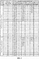
- Table 2 CSI reference signal configuration Number of CSI reference signals configured 1 or 2 4 8 ( k ', l ' ) n s mod 2 ( k ', l ') n s mod 2 ( k ', l ') n s mod 2 CSI-RS in DwPT S 0 (9,2) 0 (9,2) 0 (9,2) 0 1 (8,2) 0 (8,2) 0 (11,5) 0 2 (3,2) 0 (11,5) 0 (7,5) 0 3 (2,2) 0 (10,5) 0 4 (11,5) 0 (7,5) 0 5 (10,5) 0 (6,5) 0 6 (7,5) 0 7 (6,5) 0 8 (5,5) 0 9 (4,5) 0 10 (1,5) 0 11 (0,5) 0 12 (9,5) 0 (9,5) 0 (9,5) 0 9,5) 0 13 (8,5) 0 (8,5) 0 (8,5) 0 (8,5) 0 8,5) 0 9 (4,5) 0
- the second field is resourceConfig-r12, resourceConfig-r11 or resourceConfig-r10
- the second field has a value up to 20
- resourceConfigList-r11 resourceConfigList-r11 has a value up to 10
- the CSI-RS configuration corresponding to 1 or 2 antenna ports is not included.
- a certain offset (3 or 4 symbols) is added to the related CSI-RS pattern (for example, the CSI-RS patterns shown in FIG. 2 and FIG. 3 ) to acquire the CSI-RS pattern in the special slot.
- the operation that the second field in the RRC signaling is configured to indicate the CSI-RS pattern in the special slot specifically includes that:
- l' DwPTS represents l' in the CSI-RS pattern in the special slot
- n s mod2 DwPTS represents n s mod 2 in the CSI-RS pattern in the special slot
- l' represents l' in the default CSI-RS pattern
- n s mod 2 represents n s mod 2 in the default CSI-RS pattern.
- the default CSI-RS pattern refers to a CSI-RS pattern (as shown in FIG. 2 and FIG. 3 ) in the related standard (the 3GPP R12 standard).
- an OFDM symbol offset manner may also be adopted for representation.
- the operation that the second field in the RRC signaling is configured to indicate the CSI-RS pattern in the special slot specifically includes that:
- the embodiments further provide a CSI-RS indication method, which is applied to UE. As shown in FIG. 7 , the method includes the following steps.
- a CSI-RS pattern in the special slot is determined according to a CSI-RS pattern indicated by a second field in the RRC signaling.
- the first field indicates a CSI-RS subframe configuration
- the second field indicates a CSI-RS configuration
- values of the first field and the second field may also be different, specifically as follows:
- the preset condition refers to that the UE is new UE, rather than conventional UE (legacy UE).
- the conventional UE refers to UE meeting the 3GPP R12 (namely meeting the 3GPP R12 standard) and versions before the 3GPP R12; and correspondingly, the new UE refers to UE meeting the 3GPP R13 (meeting the 3GPP R13 standard).
- the operation that the CSI-RS pattern in the special slot is determined according to the CSI-RS pattern indicated by the second field in the RRC signaling specifically includes that:
- the 20 1-port or 2-port CSI-RS configuration parameters include the following parameters: k' is 9, l' is 2 and n s mod 2 is 0; k' is 8, l' is 2 and n s mod 2 is 0; k' is 3, l' is 2 and n s mod 2 is 0; k' is 2, l' is 2 and n s mod 2 is 0; k' is 11, l' is 5 and n s mod 2 is 0; k' is 10, l' is 5 and n s mod 2 is 0; k' is 7, l' is 5 and n s mod 2 is 0; k' is 6, l' is 5 and n s mod 2 is 0; k' is 5, l' is 5 and n s mod 2 is 0; k' is 4, l' is 5 and n s mod 2 is 0; k' is 1, l' is 5 and n s mod 2 is 0; k' is 4,
- the 10 4-port CSI-RS configuration parameters include the following parameters: k' is 9, l' is 2 and n s mod 2 is 0; k' is 8, l' is 2 and n s mod 2 is 0; k' is 11, l' is 5 and n s mod 2 is 0; k' is 10, l' is 5 and n s mod 2 is 0; k' is 7, l' is 5 and n s mod 2 is 0; k' is 6, l' is 5 and n s mod 2 is 0; k' is 5, l' is 5 and n s mod 2 is 0; k' is 8, l' is 5 and n s mod 2 is 0; k' is 9, l' is 2 and n s mod 2 is 1; and k' is 8, l' is 2 and n s mod 2 is 1.
- the 5 8-port CSI-RS configuration parameters include the following parameters: k' is 9, l' is 2 and n s mod 2 is 0; k' is 11, l' is 5 and n s mod 2 is 0; k' is 7, l' is 5 and n s mod 2 is 0; k' is 9, l' is 5 and n s mod 2 is 0; and k' is 9, l' is 2 and n s mod 2 is 1.
- a location of an RE occupied by the CSI-RS in a PRB pair is represented by (k', l'), k' represents a row where the RE is located, l' represents a column where the RE is located, n s represents a slot number, each subframe includes two slots, and mod represents remainder calculation.
- k' is numbered to be 0 ⁇ 11 from bottom to top respectively and numbers of l' are 0 ⁇ 6.
- the CSI-RS configuration parameter indication table shown in Table 2 is formed.
- the second field is resourceConfig-r12, resourceConfig-r11 or resourceConfig-r10
- the second field has a value up to 20
- resourceConfigList-r11 resourceConfigList-r11 has a value up to 10
- the CSI-RS configuration corresponding to 1 or 2 antenna ports is not included.
- a certain offset (3 or 4 symbols) is added to the related CSI-RS pattern (for example, the CSI-RS patterns shown in FIG. 2 and FIG. 3 ) to acquire the CSI-RS pattern in the special slot.
- the operation that the CSI-RS pattern in the special slot is determined according to the CSI-RS pattern indicated by the second field in the RRC signaling specifically includes that:
- l' DwPTS represents l' in the CSI-RS pattern in the special slot
- n s mod2 DwPTS represents n s mod 2 in the CSI-RS pattern in the special slot
- l' represents l' in the default CSI-RS pattern
- n s mod 2 represents n s mod 2 in the default CSI-RS pattern.
- the default CSI-RS pattern refers to a CSI-RS pattern (as shown in FIG. 2 and FIG. 3 ) in the related standard (the 3GPP R12 standard).
- an OFDM symbol offset manner may also be adopted for representation.
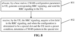
- the embodiments further provide a CSI-RS indication method. As shown in FIG. 8 , the method includes the following steps.
- a base station when a CSI-RS is transmitted through a DwPTS, a base station allocates CSI-RS configuration parameters to UE, generates RRC signaling that indicates a CSI-RS resource configuration according to information about the CSI-RS configuration parameters allocated to the UE, and sends the RRC signaling to the UE.
- a subframeConfig-r11 field in the RRC signaling is configured to indicate a special slot
- a resourceConfig-r11 field in the RRC signaling is configured to indicate a CSI-RS pattern in the special slot.
- the UE receives the RRC signaling, acquires the subframeConfig-r11 field in the RRC signaling, and when a configuration of the subframeConfig-r11 field is determined to be the special slot and the UE meets a preset condition, determines the CSI-RS pattern in the special slot according to the CSI-RS pattern indicated by the resourceConfig-r11 field in the RRC signaling.
- the first field indicates a CSI-RS subframe configuration
- the second field indicates a CSI-RS configuration
- the base station when the CSI-RS is transmitted through the DwPTS, the base station generates the RRC signaling that indicates the CSI-RS resource configuration, and sends the RRC signaling to the UE, where, when the RRC signaling that indicates the CSI-RS resource configuration is generated, the subframeConfig-r11 field in the RRC signaling is configured to indicate the special slot, and the resourceConfig-r11 field in the RRC signaling is configured to indicate the CSI-RS pattern in the special slot; and the UE receives the RRC signaling, acquires the first field in the RRC signaling, and when the first field is determined to indicate the special slot and the UE meets the preset condition, determines the CSI-RS pattern in the special slot according to the CSI-RS pattern indicated by the second field in the RRC signaling, the first field indicating the CSI-RS subframe configuration and the second field indicating the CSI-RS configuration.
- the configuration information may be described in three forms of a new table, a formula and an offset, the 36331 standard is not modified, and the new UE utilizes the related RRC signaling for re-reading. Therefore, the related RRC signaling is not required to be modified, and a signaling overhead is greatly reduced.
- the embodiments provide a base station.
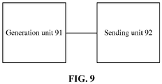
- the base station includes: a generation unit 91 and a sending unit 92, where the generation unit 91 is configured to generate RRC signaling that indicates a CSI-RS resource configuration according to information about CSI-RS configuration parameters allocated to UE; and the sending unit 92 is configured to send the RRC signaling to the UE, where, when the RRC signaling that indicates the CSI-RS resource configuration is generated, the generation unit 91 configures a first field in the RRC signaling to indicate a special slot and configures a second field in the RRC signaling to indicate a CSI-RS pattern in the special slot; and the configured special slot is configured to indicate the UE meeting a preset condition to acquire the CSI-RS pattern indicated by the second field.
- the base station further includes an allocation unit, configured to, when a CSI-RS is transmitted through a DwPTS, allocate the CSI-RS configuration parameters to the UE; and correspondingly, the generation unit 91 is configured to generate the RRC signaling that indicates the CSI-RS resource configuration according to the information about the CSI-RS configuration parameters allocated to the UE.
- the first field and the second field may adopt related fields in the 3GPP R12 standard.
- values of the first field and the second field may also be different, specifically as follows:
- the preset condition refers to that the UE is new UE, rather than conventional UE (legacy UE).
- the conventional UE refers to UE meeting the 3GPP R12 (namely meeting the 3GPP R12 standard) and versions before the 3GPP R12; and correspondingly, the new UE refers to UE meeting the 3GPP R13 (meeting the 3GPP R13 standard).
- the generation unit 91 is specifically configured to configure the second field to be a serial number corresponding to the CSI-RS pattern in the special slot in the CSI-RS configuration parameter table; and the CSI-RS configuration parameter indication table includes 20 1-port CSI-RS configuration parameters, 20 2-port CSI-RS configuration parameters, 10 4-port CSI-RS configuration parameters and 5 8-port CSI-RS configuration parameters, where the 20 1-port CSI-RS configuration parameters are the same as the 20 2-port CSI-RS configuration parameters.
- the 20 1-port or 2-port CSI-RS configuration parameters include the following parameters: k' is 9, l' is 2 and n s mod 2 is 0; k' is 8, l' is 2 and n s mod 2 is 0; k' is 3, l' is 2 and n s mod 2 is 0; k' is 2, l' is 2 and n s mod 2 is 0; k' is 11, l' is 5 and n s mod 2 is 0; k' is 10, l' is 5 and n s mod 2 is 0; k' is 7, l' is 5 and n s mod 2 is 0; k' is 6, l' is 5 and n s mod 2 is 0; k' is 5, l' is 5 and n s mod 2 is 0; k' is 4, l' is 5 and n s mod 2 is 0; k' is 1, l' is 5 and n s mod 2 is 0; k' is 4,
- the 10 4-port CSI-RS configuration parameters include the following parameters: k' is 9, l' is 2 and n s mod 2 is 0; k is 8, l' is 2 and n s mod 2 is 0; k' is 11, l' is 5 and n s mod 2 is 0; k' is 10, l' is 5 and n s mod 2 is 0; k' is 7, l' is 5 and n s mod 2 is 0; k' is 6, l' is 5 and n s mod 2 is 0; k' is 5, l' is 5 and n s mod 2 is 0; k' is 8, l' is 5 and n s mod 2 is 0; k' is 9, l' is 2 and n s mod 2 is 1; and k' is 8, l' is 2 and n s mod 2 is 1.
- the 5 8-port CSI-RS configuration parameters include the following parameters: k' is 9, l' is 2 and n s mod 2 is 0; k' is 11, l' is 5 and n s mod 2 is 0; k' is 7, l' is 5 and n s mod 2 is 0; k' is 9, l' is 5 and n s mod 2 is 0; and k' is 9, l' is 2 and n s mod 2 is 1.
- a location of an RE occupied by the CSI-RS in a PRBpair is represented by (k', l'), k' represents a row where the RE is located, l' represents a column where the RE is located, n s represents a slot number, each subframe includes two slots, and mod represents remainder calculation.
- k' is numbered to be 0 ⁇ 11 from bottom to top respectively and numbers of l' are 0 ⁇ 6.
- the second field is resourceConfig-r12, resourceConfig-r11 or resourceConfig-r10
- the second field has a value up to 20
- resourceConfigList-r11 resourceConfigList-r11 has a value up to 10
- the CSI-RS configuration corresponding to 1 or 2 antenna ports is not included.
- a certain offset (3 or 4 symbols) is added to the related CSI-RS pattern (for example, the CSI-RS patterns shown in FIG. 2 and FIG. 3 ) to acquire the CSI-RS pattern in the special slot.
- the generation unit 91 is specifically configured to configure the second field to indicate a corresponding relationship between a default CSI-RS pattern and a CSI-RS pattern in the special slot, the corresponding relationship including a corresponding relationship between l' and n s mod 2, where, when l' in the default CSI-RS pattern is more than 3, l' in the CSI-RS pattern in the special slot is a difference between l' in the default CSI-RS pattern and 3; when l' in the default CSI-RS pattern is less than or equal to 3, l' in the CSI-RS pattern in the special slot is a remainder obtained through dividing, by 7, a sum of l' in the default CSI-RS pattern and 10, i.e.
- l' DwPTS represents l' in the CSI-RS pattern in the special slot
- n s mod2 DwPTS represents n s mod 2 in the CSI-RS pattern in the special slot
- l' represents l' in the default CSI-RS pattern
- n s mod 2 represents n s mod 2 in the default CSI-RS pattern.
- the default CSI-RS pattern refers to a CSI-RS pattern (as shown in FIG. 2 and FIG. 3 ) in the related standard (the 3GPP R12 standard).
- an OFDM symbol offset manner may also be adopted for representation.
- the generation unit 91 is specifically configured to generate a CSI-RS configuration in the special slot according to an offset of the CSI-RS pattern in the special slot from the default CSI-RS pattern, where, when l' in the default CSI-RS pattern is more than 3, the CSI-RS pattern in the special slot is obtained by shifting the default CSI-RS pattern leftwards by 3 OFDM symbols; when l' in the default CSI-RS pattern is less than or equal to 3, the CSI-RS pattern in the special slot is obtained by shifting l' in the default CSI-RS pattern leftwards by 4 OFDM symbols; and the location of the RE occupied by the CSI-RS in the PRB pair is represented by (k', l'), k' represents the line where the RE is located, each row is a subcarrier, l' represents the column where the RE is located, and each column is an OFDM symbol.
- the allocation unit and the generation unit 91 may be implemented by a Central Processing Unit (CPU), Micro Control Unit (MCU), Digital Signal Processor (DSP) or Field Programmable Gate Array (FPGA) in the base station; and the sending unit 92 may be implemented in a transmitter in the base station.
- CPU Central Processing Unit
- MCU Micro Control Unit
- DSP Digital Signal Processor
- FPGA Field Programmable Gate Array
- the embodiments further provide UE.
- the UE includes: a receiving unit 101, a first acquisition unit 102 and a second acquisition unit 103, where the receiving unit 101 is configured to, when a CSI-RS is transmitted through a DwPTS, receive RRC signaling that indicates a CSI-RS resource configuration; the first acquisition unit 102 is configured to acquire a first field in the RRC signaling; and the second acquisition unit 103 is configured to, when the first field is determined to indicate a special slot and the UE meets a preset condition, determine a CSI-RS pattern in the special slot according to a CSI-RS pattern indicated by a second field in the RRC signaling.
- the first field indicates a CSI-RS subframe configuration
- the second field indicates a CSI-RS configuration
- values of the first field and the second field may also be different, specifically as follows:
- the preset condition refers to that the UE is new UE, rather than conventional UE (legacy UE).
- the conventional UE refers to UE meeting the 3GPP R12 (namely meeting the 3GPP R12 standard) and versions before the 3GPP R12; and correspondingly, the new UE refers to UE meeting the 3GPP R13 (meeting the 3GPP R13 standard).
- the second acquisition unit 103 is specifically configured to acquire, in a CSI-RS configuration parameter indication table, a serial number corresponding to the CSI-RS pattern in the special slot indicated by the second field, and determine the CSI-RS pattern in the special slot according to an acquired number of CSI-RS ports and the serial number, the CSI-RS configuration parameter indication table including 20 1-port CSI-RS configuration parameters, 20 2-port CSI-RS configuration parameters, 10 4-port CSI-RS configuration parameters and 5 8-port CSI-RS configuration parameters, where the 20 1-port CSI-RS configuration parameters are the same as the 20 2-port CSI-RS configuration parameters.
- the 20 1-port or 2-port CSI-RS configuration parameters include the following parameters: k' is 9, l' is 2 and n s mod 2 is 0; k' is 8, l' is 2 and n s mod 2 is 0; k' is 3, l' is 2 and n s mod 2 is 0; k' is 2, l' is 2 and n s mod 2 is 0; k' is 11, l' is 5 and n s mod 2 is 0; k' is 10, l' is 5 and n s mod 2 is 0; k' is 7, l' is 5 and n s mod 2 is 0; k' is 6, l' is 5 and n s mod 2 is 0; k' is 5, l' is 5 and n s mod 2 is 0; k' is 4, l' is 5 and n s mod 2 is 0; k' is 1, l' is 5 and n s mod 2 is 0; k' is 4,
- the 10 4-port CSI-RS configuration parameters include the following parameters: k' is 9, l' is 2 and n s mod 2 is 0; k' is 8, l' is 2 and n s mod 2 is 0; k' is 11, l' is 5 and n s mod 2 is 0; k' is 10, l' is 5 and n s mod 2 is 0; k' is 7, l' is 5 and n s mod 2 is 0; k' is 6, l' is 5 and n s mod 2 is 0; k' is 5, l' is 5 and n s mod 2 is 0; k' is 8, l' is 5 and n s mod 2 is 0; k' is 9, l' is 2 and n s mod 2 is 1; and k' is 8, l' is 2 and n s mod 2 is 1.
- the 5 8-port CSI-RS configuration parameters include the following parameters: k' is 9, l' is 2 and n s mod 2 is 0; k' is 11, l' is 5 and n s mod 2 is 0; k' is 7, l' is 5 and n s mod 2 is 0; k' is 9, l' is 5 and n s mod 2 is 0; and k' is 9, l' is 2 and n s mod 2 is 1.
- a location of an RE occupied by the CSI-RS in a PRBpair is represented by (k', l'), k' represents a row where the RE is located, l' represents a column where the RE is located, n s represents a slot number, each subframe includes two slots, and mod represents remainder calculation.
- k' is numbered to be 0 ⁇ 11 from bottom to top respectively and numbers of l' are 0 ⁇ 6.
- the second field is resourceConfig-r12, resourceConfig-r11 or resourceConfig-r10
- the second field has a value up to 20
- resourceConfigList-r11 resourceConfigList-r11 has a value up to 10
- the CSI-RS configuration corresponding to 1 or 2 antenna ports is not included.
- a certain offset (3 or 4 symbols) is added to the related CSI-RS pattern (for example, the CSI-RS patterns shown in FIG. 2 and FIG. 3 ) to acquire the CSI-RS pattern in the special slot.
- the second acquisition unit 103 is specifically configured to:
- l' DwPTS represents l' in the CSI-RS pattern in the special slot
- n s mod2 DwPTS represents n s mod 2 in the CSI-RS pattern in the special slot
- l' represents l' in the default CSI-RS pattern
- n s mod 2 represents n s mod 2 in the default CSI-RS pattern.
- the default CSI-RS pattern refers to a CSI-RS pattern (as shown in FIG. 2 and FIG. 3 ) in the related standard (the 3GPP R12 standard).
- an OFDM symbol offset manner may also be adopted for representation.
- the second acquisition unit 103 is specifically configured to acquire a CSI-RS configuration in the special slot indicated by the second field, where the CSI-RS configuration in the special slot is generated according to an offset of the CSI-RS pattern in the special slot from the default CSI-RS pattern, and determine the CSI-RS pattern in the special slot is determined according to the configuration and the default CSI-RS pattern, where, when l' in the default CSI-RS pattern is more than 3, the CSI-RS pattern in the special slot is obtained by shifting the default CSI-RS pattern leftwards by 3 OFDM symbols; when l' in the default CSI-RS pattern is less than or equal to 3, the CSI-RS pattern in the special slot is obtained by shifting l' in the default CSI-RS pattern leftwards by 4 OFDM symbols; and the location of the RE occupied by the CSI-RS in the PRB pair is represented by (k', l'), k' represents the row where the RE is located, each row is a subcarrier, l' represents the
- the receiving unit 101 may be implemented by a receiver in the UE; and the first acquisition unit 102 and the second acquisition unit 103 may be implemented by a CPU, MCU, DSP or FPGA in the UE.
- the embodiments further provide a CSI-RS indication system.
- the system includes: a base station 111 and UE 112, where the base station 111 is configured to, when a CSI-RS is transmitted through a DwPTS, generate RRC signaling that indicates a CSI-RS resource configuration, and send the RRC signaling to the UE 112, where, when the RRC signaling that indicates the CSI-RS resource configuration is generated, a first field in the RRC signaling is configured to indicate a special slot, and a second field in the RRC signaling is configured to indicate a CSI-RS pattern in the special slot; and the UE 112 is configured to receive the RRC signaling, acquire the first field in the RRC signaling, and when the first field is determined to indicate the special slot and the UE meets a preset condition, determine the CSI-RS pattern in the special slot according to the CSI-RS pattern indicated by the second field in the RRC signaling.
- the first field indicates a CSI-RS subframe configuration
- the second field indicates a CSI-RS configuration
- the base station when the CSI-RS is transmitted through the DwPTS, the base station generates the RRC signaling that indicates the CSI-RS resource configuration, and sends the RRC signaling to the UE, where, when the RRC signaling that indicates the CSI-RS resource configuration is generated, the first field in the RRC signaling is configured to indicate the special slot, and the second field in the RRC signaling is configured to indicate the CSI-RS pattern in the special slot; and the UE receives the RRC signaling, acquires the first field in the RRC signaling, and when the first field is determined to indicate the special slot and the UE meets the preset condition, determines the CSI-RS pattern in the special slot according to the CSI-RS pattern indicated by the second field in the RRC signaling, the first field indicating the CSI-RS sub frame configuration and the second field indicating the CSI-RS configuration.
- the configuration information may be described in three forms of a new table, a formula and an offset, the 36331 standard is not modified, and the new UE utilizes the related RRC signaling for re-reading. Therefore, the related RRC signaling is not required to be modified, and a signaling overhead is greatly reduced.
- the embodiment of the disclosure may be provided as a method, a system or a computer program product. Therefore, the disclosure may adopt a form of hardware embodiment, software embodiment and combined software and hardware embodiment. Moreover, the disclosure may adopt a form of computer program product implemented on one or more computer-available storage media (including, but not limited to, a disk memory and an optical memory) including computer-available program codes.
- a computer-available storage media including, but not limited to, a disk memory and an optical memory
- each flow and/or block in the flowcharts and/or the block diagrams and combinations of the flows and/or blocks in the flowcharts and/or the block diagrams may be implemented by computer program instructions.
- These computer program instructions may be provided for a universal computer, a dedicated computer, an embedded processor or a processor of other programmable data processing equipment to generate a machine, so that a device for realizing a function specified in one flow or more flows in the flowcharts and/or one block or more blocks in the block diagrams is generated by the instructions executed through the computer or the processor of the other programmable data processing equipment.
- These computer program instructions may also be stored in a computer-readable memory capable of guiding the computer or the other programmable data processing equipment to work in a specific manner, so that a product including an instruction device may be generated by the instructions stored in the computer-readable memory, the instruction device realizing the function specified in one flow or many flows in the flowcharts and/or one block or many blocks in the block diagrams.
- These computer program instructions may further be loaded onto the computer or the other programmable data processing equipment, so that a series of operating steps are executed on the computer or the other programmable data processing equipment to generate processing implemented by the computer, and steps for realizing the function specified in one flow or many flows in the flowcharts and/or one block or many blocks in the block diagrams are provided by the instructions executed on the computer or the other programmable data processing equipment.
Landscapes
- Engineering & Computer Science (AREA)
- Signal Processing (AREA)
- Computer Networks & Wireless Communication (AREA)
- Mobile Radio Communication Systems (AREA)
Abstract
Description
- The present application claims priority to Chinese Patent Application No.
201510746859.1, filed on November 5, 2015 - The present disclosure relates to the field of wireless communications, and particularly to a Channel State Information-Reference Signal (CSI-RS) indication method, a system, a base station and User Equipment (UE).
- A related communication system (for example, a Long Term Evolution (LTE) system, a Worldwide Interoperability for Microwave Access (WiMax) system, a Wireless Local Area Networks (WLAN) system using an 802.11n standard) adopts a 2nd-Dimensional (2D) Multiple-Input Multiple-Output (MIMO) technology, of which a basic principle is to improve transmission quality and increase a system capacity by a degree of 2D spatial freedom of an antenna on a horizontal plane.
- However, under the present background that no big breaks are made to a physical layer technology, how to further improve spectrum efficiency of a wireless communication system is a hot research issue. At present, a relatively feasible solution is to fully explore a degree of vertical spatial freedom to extend a conventional 2D MIMO technology to a 3rd-Dimensional (3D) MIMO technology and improve system performance by fully utilizing a degree of 3D spatial freedom.
- At the same time, when a 3D MIMO technology is used, along with development of a communication technology, 12 and 16-port CSI-RSs increase a pilot overhead, so that a CSI-RS is allowed to be transmitted through a Downlink Pilot Time Slot (DwPTS). However, when Radio Resource Control (RRC) signaling is adopted to indicate a configuration parameter for transmitting the CSI-RS through the DwPTS, the related RRC signaling is required to be greatly modified, so that a signaling overhead is greatly increased. Therefore, how to implement transmission of a CSI-RS through a DwPTS on the basis of not modifying related RRC signaling is a problem urgent to be solved at present.
- In order to solve the technical problem existing in a related technology, embodiments of the disclosure provide a CSI-RS indication method, a system, a base station and UE.
- In order to achieve the purpose, the technical solutions of the embodiments of the disclosure are implemented as follows.
- The embodiments of the disclosure provide a CSI-RS indication method, which may be applied to a base station. The method includes the following actions.
- When a CSI-RS is transmitted through a DwPTS, RRC signaling that indicates a CSI-RS resource configuration is generated.
- The RRC signaling is sent to UE.
- When the RRC signaling that indicates the CSI-RS resource configuration is generated, a first field in the RRC signaling may be configured to indicate a special slot, and a second field in the RRC signaling may be configured to indicate a CSI-RS pattern in the special slot; the configured special slot may be configured to indicate the UE meeting a preset condition to acquire the CSI-RS pattern indicated by the second field.
- The first field may represent a CSI-RS subframe configuration, and the second field may represent a CSI-RS configuration.
- According to an embodiment, the first field may be subframeConfig-r12, and the second field may be resourceConfig-r12;
or, the first field may be subframeConfig-r11, and the second field may be resourceConfig-r11 or resourceConfigList-r11;
or, the first field may be subframeConfig-r10, and the second field may be resourceConfig-r10. - According to an embodiment, the action of configuring the second field in the RRC signaling to indicate the CSI-RS pattern in the special slot may include the following actions.
- The second field is configured to indicate a serial number corresponding to the CSI-RS pattern in the special slot in a CSI-RS configuration parameter table.
- The CSI-RS configuration parameter indication table may include 20 1-port CSI-RS configuration parameters, 20 2-port CSI-RS configuration parameters, 10 4-port CSI-RS configuration parameters and 5 8-port CSI-RS configuration parameters.
- The 20 1-port CSI-RS configuration parameters may be the same as the 20 2-port CSI-RS configuration parameters.
- According to an embodiment, when the second field is resourceConfig-r12, resourceConfig-r11 or resourceConfig-r10, the second field may have a value up to 20; and
when the second field is resourceConfigList-r11, resourceConfigList-r11 may have a value up to 10, and may indicate multiple 4-port and 8-port CSI-RS configuration parameters. - According to an embodiment, the 20 1-port or 2-port CSI-RS configuration parameters may include the following parameters: k' is 9, l' is 2 and ns mod 2 is 0; k' is 8, l' is 2 and ns mod 2 is 0; k' is 3, l' is 2 and ns mod 2 is 0; k' is 2, l' is 2 and ns mod 2 is 0; k' is 11, l' is 5 and ns mod 2 is 0; k' is 10, l' is 5 and ns mod 2 is 0; k' is 7, l' is 5 and ns mod 2 is 0; k' is 6, l' is 5 and ns mod 2 is 0; k' is 5, l' is 5 and ns mod 2 is 0; k' is 4, l' is 5 and ns mod 2 is 0; k' is 1, l' is 5 and ns mod 2 is 0; k' is 0, l' is 5 and ns mod 2 is 0; k' is 9, l' is 5 and ns mod 2 is 0; k' is 8, l' is 5 and ns mod 2 is 0; k' is 3, l' is 5 and ns mod 2 is 0; k' is 2, l' is 5 and ns mod 2 is 0; k' is 9, l' is 2 and ns mod 2 is 1; k' is 8, l' is 2 and ns mod 2 is 1; k' is 3, l' is 2 and ns mod 2 is 1; and k' is 2, l' is 2 and ns mod 2 is 1.
- A location of a Resource Element (RE) occupied by the CSI-RS in a Physical Resource Block (PRB) pair may be represented by (k', l'), k' may represent a row where the RE is located, l' may represent a column where the RE is located, and ns may represent a slot number.
- According to an embodiment, the 10 4-port CSI-RS configuration parameters may include the following parameters: k' is 9, l' is 2 and ns mod 2 is 0; k' is 8, l' is 2 and ns mod 2 is 0; k' is 11, l' is 5 and ns mod 2 is 0; k' is 10, l' is 5 and ns mod 2 is 0; k' is 7, l' is 5 and ns mod 2 is 0; k' is 6, l' is 5 and ns mod 2 is 0; k' is 5, l' is 5 and ns mod 2 is 0; k' is 8, l' is 5 and ns mod 2 is 0; k' is 9, l' is 2 and ns mod 2 is 1; and k' is 8, l' is 2 and ns mod 2 is 1.
- The location of the RE occupied by the CSI-RS in the PRB pair may be represented by (k', l'), k' may represent the row where the RE is located, l' may represent the column where the RE is located, and ns may represent the slot number.
- According to an embodiment, the 5 8-port CSI-RS configuration parameters may include the following parameters: k' is 9, l' is 2 and ns mod 2 is 0; k' is 11, l' is 5 and ns mod 2 is 0; k' is 7, l' is 5 and ns mod 2 is 0; k' is 9, l' is 5 and ns mod 2 is 0; and k' is 9, l' is 2 and ns mod 2 is 1.
- The location of the RE occupied by the CSI-RS in the PRB pair may be represented by (k', l'), k' may represent the row where the RE is located, l' may represent the column where the RE is located, and ns may represent the slot number.
- According to an embodiment, the action of configuring the second field in the RRC signaling to indicate the CSI-RS pattern in the special slot may include the following actions.
- The second field is configured to indicate a corresponding relationship between a default CSI-RS pattern and a CSI-RS pattern in the special slot, the corresponding relationship including a corresponding relationship between l' and ns mod 2.
- When l' in the default CSI-RS pattern is more than 3, l' in the CSI-RS pattern in the special slot may be a difference between l' in the default CSI-RS pattern and 3.
- When l' in the default CSI-RS pattern is less than or equal to 3, l' in the CSI-RS pattern in the special slot may be a remainder obtained through dividing, by 7, a sum of l' in the default CSI-RS pattern and 10.
- When l' in the default CSI-RS pattern is more than 3 and ns mod 2 in the default CSI-RS pattern is equal to 1, ns mod 2 in the CSI-RS pattern in the special slot may be 1.
- Except when l' in the default CSI-RS pattern is more than 3 and ns mod 2 in the default CSI-RS pattern is equal to 1, ns mod 2 in the CSI-RS pattern in the special slot may be 0.
- The location of the RE occupied by the CSI-RS in the PRB pair may be represented by (k', l'), k' may represent the row where the RE is located, l' may represent the column where the RE is located, and ns may represent the slot number.
- According to an embodiment, the action of configuring the second field in the RRC signaling to indicate the CSI-RS pattern in the special slot may include the following actions.
- A CSI-RS configuration in the special slot is generated according to an offset of the CSI-RS pattern in the special slot from the default CSI-RS pattern.
- When l' in the default CSI-RS pattern is more than 3, the CSI-RS pattern in the special slot may be obtained by shifting the default CSI-RS pattern leftwards by 3 Orthogonal Frequency Division Multiplexing (OFDM) symbols.
- When l' in the default CSI-RS pattern is less than or equal to 3, the CSI-RS pattern in the special slot may be obtained by shifting l' in the default CSI-RS pattern leftwards by 4 OFDM symbols.
- The location of the RE occupied by the CSI-RS in the PRB pair may be represented by (k', l'), k' may represent the row where the RE is located, each row may be a subcarrier, l' may represent the column where the RE is located, and each column may be an OFDM symbol.
- The embodiments of the disclosure further provide a CSI-RS indication method, which may be applied to UE. The method includes the following actions.
- When a CSI-RS is transmitted through a DwPTS, RRC signaling that indicates a CSI-RS resource configuration is received.
- A first field in the RRC signaling is acquired.
- When the first field is determined to indicate a special slot and the UE meets a preset condition, a CSI-RS pattern in the special slot is determined according to a CSI-RS pattern indicated by a second field in the RRC signaling.
- The first field indicating a CSI-RS subframe configuration and the second field indicating a CSI-RS configuration.
- According to an embodiment, the action of determining the CSI-RS pattern in the special slot according to the CSI-RS pattern indicated by the second field in the RRC signaling may the following actions.
- A serial number corresponding to the CSI-RS pattern in the special slot indicated by the second field is acquired in a CSI-RS configuration parameter indication table.
- The CSI-RS pattern in the special slot is determined according to an acquired number of CSI-RS ports and the serial number.
- The CSI-RS configuration parameter indication table includes 20 1-port CSI-RS configuration parameters, 20 2-port CSI-RS configuration parameters, 10 4-port CSI-RS configuration parameters and 5 8-port CSI-RS configuration parameters.
- The 20 1-port CSI-RS configuration parameters may be the same as the 20 2-port CSI-RS configuration parameters.
- According to an embodiment, the action of determining the CSI-RS pattern in the special slot according to the CSI-RS pattern indicated by the second field in the RRC signaling may include the following actions.
- A corresponding relationship, indicated by the second field, between a default CSI-RS pattern and a CSI-RS pattern in the special slot is acquired, the corresponding relationship including a corresponding relationship between l' and ns mod 2.
- The CSI-RS pattern in the special slot is determined according to the corresponding relationship and the default CSI-RS pattern.
- The action of determining the CSI-RS pattern in the special slot according to the corresponding relationship and the default CSI-RS pattern may include the following actions.
- When l' in the default CSI-RS pattern is more than 3, a difference between l' in the default CSI-RS pattern and 3 is calculated to obtain l' in the CSI-RS pattern in the special slot.
- When l' in the default CSI-RS pattern is less than or equal to 3, l' in the CSI-RS pattern in the special slot is determined to be a remainder obtained through dividing, by 7, a sum of l' in the default CSI-RS pattern and 10.
- When l' in the default CSI-RS pattern is more than 3 and ns mod 2 in the default CSI-RS pattern is equal to 1, ns mod 2 in the CSI-RS pattern in the special slot is determined to be 1.
- Except when l' in the default CSI-RS pattern is more than 3 and ns mod 2 in the default CSI-RS pattern is equal to 1, ns mod 2 in the CSI-RS pattern in the special slot is determined to be 0.
- A location of an RE occupied by the CSI-RS in a PRB pair being represented by (k', l'), k' indicating a row where the RE is located, l' indicating a column where the RE is located and ns indicating a slot number.
- According to an embodiment, the action of determining the CSI-RS pattern in the special slot according to the CSI-RS pattern indicated by the second field in the RRC signaling may include the following actions.
- A CSI-RS configuration in the special slot indicated by the second field is acquired, where the CSI-RS configuration in the special slot is generated according to an offset of the CSI-RS pattern in the special slot from the default CSI-RS pattern.
- The CSI-RS pattern in the special slot is determined according to the configuration and the default CSI-RS pattern.
- When l' in the default CSI-RS pattern is more than 3, the CSI-RS pattern in the special slot may be obtained by shifting the default CSI-RS pattern leftwards by 3 OFDM symbols.
- When l' in the default CSI-RS pattern is less than or equal to 3, the CSI-RS pattern in the special slot may be obtained by shifting l' in the default CSI-RS pattern leftwards by 4 OFDM symbols.
- The location of the RE occupied by the CSI-RS in the PRB pair may be represented by (k', l'), k' may represent the row where the RE is located, each row may be a subcarrier, l' may represent the column where the RE is located, and each column may be an OFDM symbol.
- The embodiments of the disclosure further provide a base station, which may include: a generation unit and a sending unit.
- The generation unit may be configured to, when a CSI-RS is transmitted through a DwPTS, generate RRC signaling that indicates a CSI-RS resource configuration.
- The sending unit may be configured to send the RRC signaling to UE.
- When the RRC signaling that indicates the CSI-RS resource configuration is generated, the generation unit may configure a first field in the RRC signaling to indicate a special slot and configure a second field in the RRC signaling to indicate a CSI-RS pattern in the special slot; the configured special slot may be configured to indicate the UE meeting a preset condition to acquire the CSI-RS pattern indicated by the second field.
- The first field may represent a CSI-RS subframe configuration, and the second field may represent a CSI-RS configuration.
- According to an embodiment, the generation unit may specifically be configured to configure the second field to be a serial number corresponding to the CSI-RS pattern in the special slot in a CSI-RS configuration parameter table.
- The CSI-RS configuration parameter indication table may include 20 1-port CSI-RS configuration parameters, 20 2-port CSI-RS configuration parameters, 10 4-port CSI-RS configuration parameters and 5 8-port CSI-RS configuration parameters.
- The 20 1-port CSI-RS configuration parameters may be the same as the 20 2-port CSI-RS configuration parameters.
- According to an embodiment, the generation unit may specifically be configured to configure the second field to indicate a corresponding relationship between a default CSI-RS pattern and a CSI-RS pattern in the special slot, the corresponding relationship including a corresponding relationship between l' and ns mod 2.
- When l' in the default CSI-RS pattern is more than 3, l' in the CSI-RS pattern in the special slot may be a difference between l' in the default CSI-RS pattern and 3.
- When l' in the default CSI-RS pattern is less than or equal to 3, l' in the CSI-RS pattern in the special slot may be a remainder obtained through dividing, by 7, a sum of l' in the default CSI-RS pattern and 10.
- When l' in the default CSI-RS pattern is more than 3 and ns mod 2 in the default CSI-RS pattern is equal to 1, ns mod 2 in the CSI-RS pattern in the special slot may be 1.
- Except when l' in the default CSI-RS pattern is more than 3 and ns mod 2 in the default CSI-RS pattern is equal to 1, ns mod 2 in the CSI-RS pattern in the special slot may be 0.
- A location of an RE occupied by the CSI-RS in a PRB pair may be represented by (k', l'), k' may represent a row where the RE is located, l' may represent a column where the RE is located, and ns may represent a slot number.
- According to an embodiment, the generation unit may specifically be configured to:
generate a CSI-RS configuration in the special slot according to an offset of the CSI-RS pattern in the special slot from the default CSI-RS pattern. - When l' in the default CSI-RS pattern is more than 3, the CSI-RS pattern in the special slot may be obtained by shifting the default CSI-RS pattern leftwards by 3 OFDM symbols.
- When l' in the default CSI-RS pattern is less than or equal to 3, the CSI-RS pattern in the special slot may be obtained by shifting l' in the default CSI-RS pattern leftwards by 4 OFDM symbols.
- The location of the RE occupied by the CSI-RS in the PRB pair may be represented by (k', l'), k' may represent the row where the RE is located, each row may be a subcarrier, l' may represent the column where the RE is located, and each column may be an OFDM symbol.
- The embodiments of the disclosure further provide UE, which may include: a receiving unit, a first acquisition unit and a second acquisition unit.
- The receiving unit may be configured to, when a CSI-RS is transmitted through a DwPTS, receive RRC signaling that indicates a CSI-RS resource configuration.
- The first acquisition unit may be configured to acquire a first field in the RRC signaling.
- The second acquisition unit may be configured to, when the first field is determined to indicate a special slot and the UE meets a preset condition, determine a CSI-RS pattern in the special slot according to a CSI-RS pattern indicated by a second field in the RRC signaling.
- The first field indicating a CSI-RS subframe configuration and the second field indicating a CSI-RS configuration.
- According to an embodiment, the second acquisition unit may specifically be configured to acquire, in a CSI-RS configuration parameter indication table, a serial number corresponding to the CSI-RS pattern in the special slot indicated by the second field, and determine the CSI-RS pattern in the special slot according to an acquired number of CSI-RS ports and the serial number.
- The CSI-RS configuration parameter indication table includes 20 1-port CSI-RS configuration parameters, 20 2-port CSI-RS configuration parameters, 10 4-port CSI-RS configuration parameters and 5 8-port CSI-RS configuration parameters.
- The 20 1-port CSI-RS configuration parameters may be the same as the 20 2-port CSI-RS configuration parameters.
- According to an embodiment, the second acquisition unit may specifically be configured to:
acquire a corresponding relationship, indicated by the second field, between a default CSI-RS pattern and a CSI-RS pattern in the special slot, the corresponding relationship including a corresponding relationship between l' and ns mod 2, and determine the CSI-RS pattern in the special slot according to the corresponding relationship and the default CSI-RS pattern. - The action of determining the CSI-RS pattern in the special slot according to the corresponding relationship and the default CSI-RS pattern may include the following actions.
- When l' in the default CSI-RS pattern is more than 3, a difference between l' in the default CSI-RS pattern and 3 is calculated to obtain l' in the CSI-RS pattern in the special slot.
- When l' in the default CSI-RS pattern is less than or equal to 3, l' in the CSI-RS pattern in the special slot is determined to be a remainder obtained through dividing, by 7, a sum of l' in the default CSI-RS pattern and 10.
- When l' in the default CSI-RS pattern is more than 3 and ns mod 2 in the default CSI-RS pattern is equal to 1, ns mod 2 in the CSI-RS pattern in the special slot is determined to be 1.
- Except when l' in the default CSI-RS pattern is more than 3 and ns mod 2 in the default CSI-RS pattern is equal to 1, ns mod 2 in the CSI-RS pattern in the special slot is determined to be 0.
- A location of an RE occupied by the CSI-RS in a PRB pair being represented by (k', l'), k' indicating a row where the RE is located, l' indicating a column where the RE is located and ns indicating a slot number.
- According to an embodiment, the second acquisition unit may specifically be configured to:
acquire a CSI-RS configuration in the special slot indicated by the second field, where the CSI-RS configuration in the special slot is generated according to an offset of the CSI-RS pattern in the special slot from the default CSI-RS pattern, and determine the CSI-RS pattern in the special slot according to the configuration and the default CSI-RS pattern. - When l' in the default CSI-RS pattern is more than 3, the CSI-RS pattern in the special slot may be obtained by shifting the default CSI-RS pattern leftwards by 3 OFDM symbols.
- When l' in the default CSI-RS pattern is less than or equal to 3, the CSI-RS pattern in the special slot may be obtained by shifting l' in the default CSI-RS pattern leftwards by 4 OFDM symbols.
- The location of the RE occupied by the CSI-RS in the PRB pair may be represented by (k', l'), k' may represent the row where the RE is located, each row may be a subcarrier, l' may represent the column where the RE is located, and each column may be an OFDM symbol.
- The embodiments of the disclosure further provide a CSI-RS indication system, which may include: a base station and UE.
- The base station may be configured to, when a CSI-RS is transmitted through a DwPTS, generate RRC signaling that indicates a CSI-RS resource configuration, and send the RRC signaling to the UE, where, when the RRC signaling that indicates the CSI-RS resource configuration is generated, a first field in the RRC signaling may be configured to indicate a special slot, and a second field in the RRC signaling may be configured to indicate a CSI-RS pattern in the special slot.
- The UE may be configured to receive the RRC signaling, acquire the first field in the RRC signaling, and when the first field is determined to indicate the special slot and the UE meets a preset condition, determine the CSI-RS pattern in the special slot according to the CSI-RS pattern indicated by the second field in the RRC signaling.
- The first field indicates a CSI-RS subframe configuration and the second field indicates a CSI-RS configuration.
- According to the CSI-RS indication method, system, base station and UE provided by the embodiments of the disclosure, when the CSI-RS is transmitted through the DwPTS, the RRC signaling that indicates the CSI-RS resource configuration is generated. The RRC signaling is sent to the UE. When the RRC signaling that indicates the CSI-RS resource configuration is generated, the first field in the RRC signaling is configured to indicate the special slot, the second field in the RRC signaling is configured to indicate the CSI-RS pattern in the special slot, and the UE receives the RRC signaling. The first field in the RRC signaling is acquired. When the first field is determined to indicate the special slot and the UE meets the preset condition, the CSI-RS pattern in the special slot is determined according to the CSI-RS pattern indicated by the second field in the RRC signaling. The first field indicates the CSI-RS subframe configuration and the second field indicates the CSI-RS configuration. Therefore, the related RRC signaling is not required to be modified, and a signaling overhead is greatly reduced.
- In the drawings (which are not always drawn to scale), similar parts may be described with similar drawing reference signs in different views. Similar drawing reference signs with different letter suffixes may represent different examples of similar parts. The drawings substantially show each embodiment discussed in the disclosure exemplarily but unlimitedly.
-
FIG. 1 is a principle and effect diagram of a 3D MIMO technology according to the related technology. -
FIG. 2A-B are schematic diagrams of a CSI-RS pattern in an 8-port CSI-RS indication according to the related technology. -
FIG. 3 is a CSI-RS configuration parameter indication table according to the related technology. -
FIG. 4 is a design diagram of an 8-port CSI-RS in specialslot configurations # -
FIG. 5 is a design diagram of an 8-port CSI-RS in specialslot configurations # -
FIG. 6 is a flowchart of a CSI-RS indication method for a base station side according to some embodiments of the disclosure. -
FIG. 7 is a flowchart of a CSI-RS indication method for a UE side according to some embodiments of the disclosure. -
FIG. 8 is a flowchart of a CSI-RS indication method according to some embodiments of the disclosure. -
FIG. 9 is a structure diagram of a base station according to some embodiments of the disclosure. -
FIG. 10 is a structure diagram of UE according to some embodiments of the disclosure. -
FIG. 11 is a structure diagram of a CSI-RS indication system according to some embodiments of the disclosure. - The disclosure will further be described below in combination with the drawings and embodiments in detail.
- Before the embodiments of the disclosure are described, related contents of 2D MIMO and 3D MIMO technologies are understood with reference to
FIG. 1 . - Specifically, in the 2D MIMO technology, an antenna architecture is as follows: multiple array elements are adopted in a vertical dimension, that is, N antennae are adopted, so that a higher antenna gain is obtained; and each antenna array element in the vertical dimension adopts a fixed weight to ensure that a required beam pattern is obtained in the vertical dimension. Therefore, under such a condition, it is impossible to use a precoding solution in the vertical dimension in the MIMO technology.
- In the 3D MIMO technology, for fully utilizing the MIMO technology in the vertical dimension, weighting factors of different antenna array elements in the vertical dimension may be controlled to form different beams. The beams in the vertical dimension may be effectively distinguished, thereby providing multiple-user multiplexing in the vertical dimension and increasing a system capacity, as shown in
FIG. 1 . A conventional LTE system supports a design ofmaximally 8 antennae, and 3D MIMO extends an antenna channel number, and supports a 3D antenna form with a channel number of 16, 32, 64, 128 and the like. - Second, design of a CSI-RS in the related technology is understood.
FIG. 2 is a related CSI-RS pattern in an 8-port CSI-RS indication, andFIG. 3 is a related configuration parameter indication table. In combination withFIG. 2 andFIG. 3 , it can be seen that, in the present standard 3rd Generation Partnership Project (3GPP) Release 12 (R12), an overhead of a CSI-RS configuration parameter is an RE in a PRB of a port. FromFIG. 2 , it can be seen that, in the related standard, there may be multiple CSI-RS configurations. For example, in an 8-port Frequency Division Duplexing (FDD) system, there are 5 configurations (distinguished with different filling colors), and the specific CSI-RS configuration to be adopted is notified to UE through high-layer signaling. - Moreover, it is specified in the related standard that, in a special slot (DwPTS) of a Time Division Duplexing (TDD) system, no CSI-RS is sent (The UE shall assume that CSI reference signals are not transmitted in the DwPTS(s) in case of frame structure type 2).
- However, introduction of 12 and 16-port CSI-RSs into a new standard (3GPP R13) increases a pilot overhead, so that CSI-RSs have been allowed in discussion of the R13 standard to be send in downlink parts (DwPTSs) of special slots.
- Table 1 shows a configuration of a special slot. From Table 1, it can be seen that #1, 2, 3, 4, 6, 7 and 8 are configured for the special slot (a DwPTS includes 9∼12 OFDM symbols), so that a CSI-RS may be transmitted in the DwPTS. While in another special slot configuration, the DwPTS includes a small number of OFDM symbols, so that supporting transmission of the CSI-RS is not suggested.
Table 1 Special subframe configuration Normal cyclic prefix in downlink Extended cyclic prefix in downlink DwPTS UpPTS DwPTS UpPTS Normal cyclic prefix in uplink Extended cyclic prefix in uplink Normal cyclic prefix in uplink Extended cyclic prefix in uplink 0 6592·T s 2192·T s 2560·T s 7680·T s 2192·T s 2560· T s1 19760·T s 20480· T s2 21952·T s 23040· T s3 24144·T s 25600· T s4 26336·T s 7680·T s 4384·T s 5120· T s5 6592·T s 4384·T s 5120·T s 20480· T s6 19760·T s 23040· T s7 21952·T s 12800· T s8 24144·T s - - - 9 13168·T s - - - - On such a basis, someone proposes 8-port CSI-RS designs shown in
FIG. 4 andFIG. 5 in case of transmission of CSI-RSs through a DwPTS, i.e. CSI-RS patterns in a CSI-RS indication. - During a practical application, a 16-port design may adopt a combination of 2 8-port designs, and a 12-port design may adopt a combined form of 3 4-port designs or an 8+4 design.
- In addition, at present, when CSI-RS configuration parameter information is acquired, UE acquires a sending period of a CSI-RS and an offset of a subframe where it is located through subframeConfig-r10 in an Information Element (IE)-CSI-RS-Config in TS36.331, and then acquires a specific CSI-RS pattern through resourceConfigu-r10. Or the UE acquires the sending period of the CSI-RS and the offset of the subframe where it is located through subframeConfig-r11 in an IE-CSI-RS-ConfigNZP, and then acquires the specific CSI-RS pattern through resourceConfig-r11. Or the UE acquires the sending period of the CSI-RS and the offset of the subframe where it is located through subframeConfig-r11 in an IE-CSI-RS-ConfigZP, and then acquires the specific CSI-RS pattern through resourceConfigList-r11. Or the UE acquires the sending period of the CSI-RS and the offset of the subframe where it is located through subframeConfig-r12 in CSI-IM-Config, and then acquires the specific CSI-RS pattern through resourceConfig-r12.
- From the above descriptions, it can be seen that, during transmission of the CSI-RS through the DwPTS, when the corresponding CSI-RS configuration parameter information is still transmitted to the UE through RRC signaling at this point, if a format of the related RRC signaling is still adopted, there may exist the following condition:
considering 20 new configurations about the CSI-RS in the DwPTS are not included in the related RRC signaling resourceConfig-r12, resourceConfig-r11, resourceConfiguList-r11 and resourceConfig-r10, so that it is necessary to add a piece of new signaling to indicate a CSI-RS configuration in the special slot. A field dedicated to indicate a CSI-RS configuration of R13 may be added, for example, resourceConfig-r13 and/or resourceConfigList-r13. - In such a manner, the solution not only involves standard modification to a Radio Access Network 1 (RANI), but also requires modification to a standard protocol of a RAN2, so that the standard is greatly modified, that is, the related RRC signaling is required to be modified more. Therefore, a signaling overhead is increased.
- On such a basis, in each embodiment of the disclosure: when a CSI-RS is transmitted through a DwPTS, a base station generates RRC signaling that indicates a CSI-RS resource configuration, and sends the RRC signaling to UE, where, when the RRC signaling that indicates the CSI-RS resource configuration is generated, a first field in the RRC signaling is configured to indicate a special slot, and a second field in the RRC signaling is configured to indicate a CSI-RS pattern in the special slot; and
the UE receives the RRC signaling, acquires the first field in the RRC signaling, and when the first field is determined to indicate the special slot and the UE meets a preset condition, the CSI-RS pattern in the special slot is determined according to the CSI-RS pattern indicated by the second field in the RRC signaling,
the first field indicating a CSI-RS subframe configuration and the second field indicating the CSI-RS configuration. - In the embodiments, the embodiments provide a CSI-RS indication method, which is applied to a base station. As shown in
FIG. 6 , the method includes the following steps. - In 601, when a CSI-RS is transmitted through a DwPTS, CSI-RS configuration parameters are allocated to UE.
- In 602, RRC signaling that indicates a CSI-RS resource configuration is generated according to information about the CSI-RS configuration parameters allocated to the UE, and the RRC signaling is sent to the UE.
- Here, when the RRC signaling that indicates the CSI-RS resource configuration is generated, a first field in the RRC signaling is configured to indicate a special slot, and a second field in the RRC signaling is configured to indicate a CSI-RS pattern in the special slot; and the configured special slot is configured to indicate the UE meeting a preset condition to acquire the CSI-RS pattern indicated by the second field.
- Here, the first field indicates a CSI-RS subframe configuration, and the second field indicates a CSI-RS configuration.
- The first field and the second field may adopt related fields in the 3GPP R12 standard.
- During a practical application, for different protocol versions, values of the first field and the second field may also be different, specifically as follows:
- for the 3GPP R12, the first field is subframeConfig-r12, and the second field is resourceConfig-r12;
- for the 3GPP R11, the first field is subframeConfig-r11, and the second field is resourceConfig-r11 or resourceConfigList-r11; and
- for the 3GPP R10, the first field may be subframeConfig-r10, and the second field may be resourceConfig-r10.
- The preset condition refers to that the UE is new UE, rather than conventional UE (legacy UE).
- Where, the conventional UE refers to UE meeting the 3GPP R12 (namely meeting the 3GPP R12 standard) and versions before the 3GPP R12; and correspondingly, the new UE refers to UE meeting the 3GPP R13 (meeting the 3GPP R13 standard).
- During a practical application, when the conventional UE receives the RRC signaling and it is determined that the first field in the RRC signaling indicates the special slot, mistaken transmission is determined.
- When a CSI-RS configuration parameter indication table is adopted, the operation that the second field in the RRC signaling is configured to indicate the CSI-RS pattern in the special slot specifically includes that:
- the second field is configured to indicate a serial number corresponding to the CSI-RS pattern in the special slot in the CSI-RS configuration parameter table; and
- the CSI-RS configuration parameter indication table includes 20 1-port CSI-RS configuration parameters, 20 2-port CSI-RS configuration parameters, 10 4-port CSI-RS configuration parameters and 5 8-port CSI-RS configuration parameters, where
- the 20 1-port CSI-RS configuration parameters are the same as the 20 2-port CSI-RS configuration parameters.
- Here, the 20 1-port or 2-port CSI-RS configuration parameters include the following parameters: k' is 9, l' is 2 and ns mod 2 is 0; k' is 8, l' is 2 and ns mod 2 is 0; k' is 3, l' is 2 and ns mod 2 is 0; k' is 2, l' is 2 and ns mod 2 is 0; k' is 11, l' is 5 and ns mod 2 is 0; k' is 10, l' is 5 and ns mod 2 is 0; k' is 7, l' is 5 and ns mod 2 is 0; k' is 6, l' is 5 and ns mod 2 is 0; k' is 5, l' is 5 and ns mod 2 is 0; k' is 4, l' is 5 and ns mod 2 is 0; k' is 1, l' is 5 and ns mod 2 is 0; k' is 0, l' is 5 and ns mod 2 is 0; k' is 9, l' is 5 and ns mod 2 is 0; k' is 8, l' is 5 and ns mod 2 is 0; k' is 3, l' is 5 and ns mod 2 is 0; k' is 2, l' is 5 and ns mod 2 is 0; k' is 9, l' is 2 and ns mod 2 is 1; k' is 8, l' is 2 and ns mod 2 is 1; k' is 3, l' is 2 and ns mod 2 is 1; and k' is 2, l' is 2 and ns mod 2 is 1.
- The 10 4-port CSI-RS configuration parameters include the following parameters: k' is 9, l' is 2 and ns mod 2 is 0; k' is 8, l' is 2 and ns mod 2 is 0; k' is 11, l' is 5 and ns mod 2 is 0; k' is 10, l' is 5 and ns mod 2 is 0; k' is 7, l' is 5 and ns mod 2 is 0; k' is 6, l' is 5 and ns mod 2 is 0; k' is 5, l' is 5 and ns mod 2 is 0; k' is 8, l' is 5 and ns mod 2 is 0; k' is 9, l' is 2 and ns mod 2 is 1; and k' is 8, l' is 2 and ns mod 2 is 1.
- The 5 8-port CSI-RS configuration parameters include the following parameters: k' is 9, l' is 2 and ns mod 2 is 0; k' is 11, l' is 5 and ns mod 2 is 0; k' is 7, l' is 5 and ns mod 2 is 0; k' is 9, l' is 5 and ns mod 2 is 0; and k' is 9, l' is 2 and ns mod 2 is 1.
- Where, a location of an RE occupied by the CSI-RS in a PRB pair is represented by (k', l'), k' represents a row where the RE is located, l' represents a column where the RE is located, ns represents a slot number, each subframe includes two slots, and mod represents remainder calculation.
- Herein, during a practical application, according to the CSI-RS pattern shown in
FIG. 4 andFIG. 5 , a base station side selects the CSI-RS pattern inFIG. 4 orFIG. 5 for CSI-RS transmission according to a configuration of the special slot, k being numbered to be 0∼11 from bottom to top respectively and numbers of l' being 0∼6. - On the basis of the abovementioned conditions, the CSI-RS configuration parameter indication table shown in Table 2 is formed.
Table 2 CSI reference signal configuration Number of CSI reference signals configured 1 or 2 4 8 (k', l' ) ns mod 2 (k', l') ns mod 2 (k', l') ns mod 2 CSI-RS in DwPT S 0 (9,2) 0 (9,2) 0 (9,2) 0 1 (8,2) 0 (8,2) 0 (11,5) 0 2 (3,2) 0 (11,5) 0 (7,5) 0 3 (2,2) 0 (10,5) 0 4 (11,5) 0 (7,5) 0 5 (10,5) 0 (6,5) 0 6 (7,5) 0 7 (6,5) 0 8 (5,5) 0 9 (4,5) 0 10 (1,5) 0 11 (0,5) 0 12 (9,5) 0 (9,5) 0 (9,5) 0 13 (8,5) 0 (8,5) 0 (9,2) 1 14 (3,5) 0 (9,2) 1 15 (2,5) 0 (8,2) 1 16 (9,2) 1 17 (8,2) 1 18 (3,2) 1 19 (2,2) 1 - It should be noted that, during a practical application,
serial numbers 0∼19 in Table 2 are not limited. - When the second field is resourceConfig-r12, resourceConfig-r11 or resourceConfig-r10, the second field has a value up to 20; and
when the second field is resourceConfigList-r11, resourceConfigList-r11 has a value up to 10, and may indicate multiple 4-port and 8-port CSI-RS configuration parameters. At this point, the CSI-RS configuration corresponding to 1 or 2 antenna ports is not included. - In addition, during a practical application, for further reducing modification to the standard, namely reducing modification to the RRC signaling, a certain offset (3 or 4 symbols) is added to the related CSI-RS pattern (for example, the CSI-RS patterns shown in
FIG. 2 andFIG. 3 ) to acquire the CSI-RS pattern in the special slot. - On such a basis, the operation that the second field in the RRC signaling is configured to indicate the CSI-RS pattern in the special slot specifically includes that:
- the second field is configured to indicate a corresponding relationship between a default CSI-RS pattern and a CSI-RS pattern in the special slot, the corresponding relationship including a corresponding relationship between l' and ns mod 2, where,
- when l' in the default CSI-RS pattern is more than 3, l' in the CSI-RS pattern in the special slot is a difference between l' in the default CSI-RS pattern and 3;
- when l' in the default CSI-RS pattern is less than or equal to 3, l' in the CSI-RS pattern in the special slot is a remainder obtained through dividing, by 7, a sum of l' in the default CSI-RS pattern and 10;
- when l' in the default CSI-RS pattern is more than 3 and ns mod 2 in the default CSI-RS pattern is equal to 1, ns mod 2 in the CSI-RS pattern in the special slot is 1; and
- except when l' in the default CSI-RS pattern is more than 3 and ns mod 2 in the default CSI-RS pattern is equal to 1, ns mod 2 in the CSI-RS pattern in the special slot is 0.
- Where, when a formula is adopted to represent the corresponding relationship and the CSI-RS pattern in the special slot:


- Here, l'DwPTS represents l' in the CSI-RS pattern in the special slot, ns mod2 DwPTS represents ns mod 2 in the CSI-RS pattern in the special slot, l' represents l' in the default CSI-RS pattern, and ns mod 2 represents ns mod 2 in the default CSI-RS pattern.
- The default CSI-RS pattern refers to a CSI-RS pattern (as shown in
FIG. 2 andFIG. 3 ) in the related standard (the 3GPP R12 standard). - Besides the corresponding relationship adopted to represent the CSI-RS pattern in the configured special slot, an OFDM symbol offset manner may also be adopted for representation.
- On such a basis, the operation that the second field in the RRC signaling is configured to indicate the CSI-RS pattern in the special slot specifically includes that:
- a CSI-RS configuration in the special slot is generated according to an offset of the CSI-RS pattern in the special slot from the default CSI-RS pattern, where,
- when l' in the default CSI-RS pattern is more than 3, the CSI-RS pattern in the special slot is obtained by shifting the default CSI-RS pattern leftwards by 3 OFDM symbols;
- when l' in the default CSI-RS pattern is less than or equal to 3, the CSI-RS pattern in the special slot is obtained by shifting l' in the default CSI-RS pattern leftwards by 4 OFDM symbols; and
- the location of the RE occupied by the CSI-RS in the PRB pair is represented by (k', l'), k' represents the row where the RE is located, each row is a subcarrier, l' represents the column where the RE is located, and each column is an OFDM symbol.
- The embodiments further provide a CSI-RS indication method, which is applied to UE. As shown in
FIG. 7 , the method includes the following steps. - In 701, when a CSI-RS is transmitted through a DwPTS, RRC signaling that indicates a CSI-RS resource configuration is received.
- In 702, a first field in the RRC signaling is acquired.
- In 703, when the first field is determined to indicate a special slot and the UE meets a preset condition, a CSI-RS pattern in the special slot is determined according to a CSI-RS pattern indicated by a second field in the RRC signaling.
- Here, the first field indicates a CSI-RS subframe configuration, and the second field indicates a CSI-RS configuration.
- During a practical application, for different protocol versions, values of the first field and the second field may also be different, specifically as follows:
- for the 3GPP R12, the first field is subframeConfig-r12, and the second field is resourceConfig-r12;
- for the 3GPP R11, the first field is subframeConfig-r11, and the second field is resourceConfig-r11 or resourceConfigList-r11; and
- for the 3GPP R10, the first field may be subframeConfig-r10, and the second field may be resourceConfig-r10.
- The preset condition refers to that the UE is new UE, rather than conventional UE (legacy UE).
- Where, the conventional UE refers to UE meeting the 3GPP R12 (namely meeting the 3GPP R12 standard) and versions before the 3GPP R12; and correspondingly, the new UE refers to UE meeting the 3GPP R13 (meeting the 3GPP R13 standard).
- During a practical application, when the conventional UE receives the RRC signaling and it is determined that the first field in the RRC signaling indicates the special slot, mistaken transmission is determined.
- In the embodiments, when a CSI-RS configuration parameter indication table is adopted, the operation that the CSI-RS pattern in the special slot is determined according to the CSI-RS pattern indicated by the second field in the RRC signaling specifically includes that:
- a serial number corresponding to the CSI-RS pattern in the special slot indicated by the second field is acquired in a CSI-RS configuration parameter indication table; and
- the CSI-RS pattern in the special slot is determined according to an acquired number of CSI-RS ports and the serial number,
- the CSI-RS configuration parameter indication table including 20 1-port CSI-RS configuration parameters, 20 2-port CSI-RS configuration parameters, 10 4-port CSI-RS configuration parameters and 5 8-port CSI-RS configuration parameters, where
- the 20 1-port CSI-RS configuration parameters are the same as the 20 2-port CSI-RS configuration parameters.
- Here, the 20 1-port or 2-port CSI-RS configuration parameters include the following parameters: k' is 9, l' is 2 and ns mod 2 is 0; k' is 8, l' is 2 and ns mod 2 is 0; k' is 3, l' is 2 and ns mod 2 is 0; k' is 2, l' is 2 and ns mod 2 is 0; k' is 11, l' is 5 and ns mod 2 is 0; k' is 10, l' is 5 and ns mod 2 is 0; k' is 7, l' is 5 and ns mod 2 is 0; k' is 6, l' is 5 and ns mod 2 is 0; k' is 5, l' is 5 and ns mod 2 is 0; k' is 4, l' is 5 and ns mod 2 is 0; k' is 1, l' is 5 and ns mod 2 is 0; k' is 0, l' is 5 and ns mod 2 is 0; k' is 9, l' is 5 and ns mod 2 is 0; k' is 8, l' is 5 and ns mod 2 is 0; k' is 3, l' is 5 and ns mod 2 is 0; k' is 2, l' is 5 and ns mod 2 is 0; k' is 9, l' is 2 and ns mod 2 is 1; k' is 8, l' is 2 and ns mod 2 is 1; k' is 3, l' is 2 and ns mod 2 is 1; and k' is 2, l' is 2 and ns mod 2 is 1.
- The 10 4-port CSI-RS configuration parameters include the following parameters: k' is 9, l' is 2 and ns mod 2 is 0; k' is 8, l' is 2 and ns mod 2 is 0; k' is 11, l' is 5 and ns mod 2 is 0; k' is 10, l' is 5 and ns mod 2 is 0; k' is 7, l' is 5 and ns mod 2 is 0; k' is 6, l' is 5 and ns mod 2 is 0; k' is 5, l' is 5 and ns mod 2 is 0; k' is 8, l' is 5 and ns mod 2 is 0; k' is 9, l' is 2 and ns mod 2 is 1; and k' is 8, l' is 2 and ns mod 2 is 1.
- The 5 8-port CSI-RS configuration parameters include the following parameters: k' is 9, l' is 2 and ns mod 2 is 0; k' is 11, l' is 5 and ns mod 2 is 0; k' is 7, l' is 5 and ns mod 2 is 0; k' is 9, l' is 5 and ns mod 2 is 0; and k' is 9, l' is 2 and ns mod 2 is 1.
- Where, a location of an RE occupied by the CSI-RS in a PRB pair is represented by (k', l'), k' represents a row where the RE is located, l' represents a column where the RE is located, ns represents a slot number, each subframe includes two slots, and mod represents remainder calculation.
- Herein, during a practical application, according to the CSI-RS pattern shown in
FIG. 4 andFIG. 5 , k' is numbered to be 0∼11 from bottom to top respectively and numbers of l' are 0∼6. - On the basis of the abovementioned conditions, the CSI-RS configuration parameter indication table shown in Table 2 is formed.
when the second field is resourceConfig-r12, resourceConfig-r11 or resourceConfig-r10, the second field has a value up to 20; and
when the second field is resourceConfigList-r11, resourceConfigList-r11 has a value up to 10, and may indicate multiple 4-port and 8-port CSI-RS configuration parameters. At this point, the CSI-RS configuration corresponding to 1 or 2 antenna ports is not included. - In addition, during a practical application, for further reducing modification to the standard, namely reducing modification to the RRC signaling, a certain offset (3 or 4 symbols) is added to the related CSI-RS pattern (for example, the CSI-RS patterns shown in
FIG. 2 andFIG. 3 ) to acquire the CSI-RS pattern in the special slot. - On such a basis, the operation that the CSI-RS pattern in the special slot is determined according to the CSI-RS pattern indicated by the second field in the RRC signaling specifically includes that:
- a corresponding relationship, indicated by the second field, between a default CSI-RS pattern and a CSI-RS pattern in the special slot is acquired, the corresponding relationship including a corresponding relationship between l' and ns mod 2; and
- the CSI-RS pattern in the special slot is determined according to the corresponding relationship and the default CSI-RS pattern, where
- the operation that the CSI-RS pattern in the special slot is determined according to the corresponding relationship and the default CSI-RS pattern includes that:
- when l' in the default CSI-RS pattern is more than 3, a difference between l' in the default CSI-RS pattern and 3 is calculated to obtain l' in the CSI-RS pattern in the special slot;
- when l' in the default CSI-RS pattern is less than or equal to 3, l' in the CSI-RS pattern in the special slot is determined to be a remainder obtained through dividing, by 7, a sum of l' in the default CSI-RS pattern and 10, i.e. (1'+10)mod7;
- when l' in the default CSI-RS pattern is more than 3 and ns mod 2 in the default CSI-RS pattern is equal to 1, ns mod 2 in the CSI-RS pattern in the special slot is determined to be 1; and
- except when l' in the default CSI-RS pattern is more than 3 and ns mod 2 in the default CSI-RS pattern is equal to 1, ns mod 2 in the CSI-RS pattern in the special slot is determined to be 0.
- Where, when a formula is adopted to represent the corresponding relationship and the CSI-RS pattern in the special slot:


- Here, l'DwPTS represents l' in the CSI-RS pattern in the special slot, ns mod2 DwPTS represents ns mod 2 in the CSI-RS pattern in the special slot, l' represents l' in the default CSI-RS pattern, and ns mod 2 represents ns mod 2 in the default CSI-RS pattern.
- The default CSI-RS pattern refers to a CSI-RS pattern (as shown in
FIG. 2 andFIG. 3 ) in the related standard (the 3GPP R12 standard). - Besides the corresponding relationship adopted to represent the CSI-RS pattern in the configured special slot, an OFDM symbol offset manner may also be adopted for representation.
- The operation that the CSI-RS pattern in the special slot is determined according to the CSI-RS pattern indicated by the second field in the RRC signaling includes that:
- a CSI-RS configuration in the special slot indicated by the second field is acquired, where the CSI-RS configuration in the special slot is generated according to an offset of the CSI-RS pattern in the special slot from the default CSI-RS pattern; and
- the CSI-RS pattern in the special slot is determined according to the configuration and the default CSI-RS pattern, where,
- when l' in the default CSI-RS pattern is more than 3, the CSI-RS pattern in the special slot is obtained by shifting the default CSI-RS pattern leftwards by 3 OFDM symbols;
- when l' in the default CSI-RS pattern is less than or equal to 3, the CSI-RS pattern in the special slot is obtained by shifting l' in the default CSI-RS pattern leftwards by 4 OFDM symbols; and
- the location of the RE occupied by the CSI-RS in the PRB pair is represented by (k', l'), k' represents the row where the RE is located, each row is a subcarrier, l' represents the column where the RE is located, and each column is an OFDM symbol.
- The embodiments further provide a CSI-RS indication method. As shown in
FIG. 8 , the method includes the following steps. - In 801, when a CSI-RS is transmitted through a DwPTS, a base station allocates CSI-RS configuration parameters to UE, generates RRC signaling that indicates a CSI-RS resource configuration according to information about the CSI-RS configuration parameters allocated to the UE, and sends the RRC signaling to the UE.
- Where, when the RRC signaling that indicates the CSI-RS resource configuration is generated, a subframeConfig-r11 field in the RRC signaling is configured to indicate a special slot, and a resourceConfig-r11 field in the RRC signaling is configured to indicate a CSI-RS pattern in the special slot.
- In 802, the UE receives the RRC signaling, acquires the subframeConfig-r11 field in the RRC signaling, and when a configuration of the subframeConfig-r11 field is determined to be the special slot and the UE meets a preset condition, determines the CSI-RS pattern in the special slot according to the CSI-RS pattern indicated by the resourceConfig-r11 field in the RRC signaling.
- Here, the first field indicates a CSI-RS subframe configuration, and the second field indicates a CSI-RS configuration.
- It should be noted that specific processing processes of the base station and the UE have been described above in detail and will not be elaborated herein.
- According to the CSI-RS indication method provided by the embodiments, when the CSI-RS is transmitted through the DwPTS, the base station generates the RRC signaling that indicates the CSI-RS resource configuration, and sends the RRC signaling to the UE, where, when the RRC signaling that indicates the CSI-RS resource configuration is generated, the subframeConfig-r11 field in the RRC signaling is configured to indicate the special slot, and the resourceConfig-r11 field in the RRC signaling is configured to indicate the CSI-RS pattern in the special slot; and the UE receives the RRC signaling, acquires the first field in the RRC signaling, and when the first field is determined to indicate the special slot and the UE meets the preset condition, determines the CSI-RS pattern in the special slot according to the CSI-RS pattern indicated by the second field in the RRC signaling, the first field indicating the CSI-RS subframe configuration and the second field indicating the CSI-RS configuration. Only a CSI-RS chapter in the 36211 standard is required to be modified, that is, the configuration in the DwPTS is added, the configuration information may be described in three forms of a new table, a formula and an offset, the 36331 standard is not modified, and the new UE utilizes the related RRC signaling for re-reading. Therefore, the related RRC signaling is not required to be modified, and a signaling overhead is greatly reduced.
- In the embodiments, for implementing the method of the embodiments of the disclosure, the embodiments provide a base station. As shown in
FIG. 9 , the base station includes: ageneration unit 91 and a sendingunit 92, where
thegeneration unit 91 is configured to generate RRC signaling that indicates a CSI-RS resource configuration according to information about CSI-RS configuration parameters allocated to UE; and
the sendingunit 92 is configured to send the RRC signaling to the UE, where,
when the RRC signaling that indicates the CSI-RS resource configuration is generated, thegeneration unit 91 configures a first field in the RRC signaling to indicate a special slot and configures a second field in the RRC signaling to indicate a CSI-RS pattern in the special slot; and the configured special slot is configured to indicate the UE meeting a preset condition to acquire the CSI-RS pattern indicated by the second field. - Here, during a practical application, the base station further includes an allocation unit, configured to, when a CSI-RS is transmitted through a DwPTS, allocate the CSI-RS configuration parameters to the UE; and
correspondingly, thegeneration unit 91 is configured to generate the RRC signaling that indicates the CSI-RS resource configuration according to the information about the CSI-RS configuration parameters allocated to the UE. - The first field and the second field may adopt related fields in the 3GPP R12 standard.
- During a practical application, for different protocol versions, values of the first field and the second field may also be different, specifically as follows:
- for the 3GPP R12, the first field is subframeConfig-r12, and the second field is resourceConfig-r12;
- for the 3GPP R11, the first field is subframeConfig-r11, and the second field is resourceConfig-r11 or resourceConfigList-r11; and
- for the 3GPP R10, the first field may be subframeConfig-r10, and the second field may be resourceConfig-r10.
- The preset condition refers to that the UE is new UE, rather than conventional UE (legacy UE).
- Where, the conventional UE refers to UE meeting the 3GPP R12 (namely meeting the 3GPP R12 standard) and versions before the 3GPP R12; and correspondingly, the new UE refers to UE meeting the 3GPP R13 (meeting the 3GPP R13 standard).
- During a practical application, when the conventional UE receives the RRC signaling and it is determined that the first field in the RRC signaling indicates the special slot, mistaken transmission is determined.
- When a CSI-RS configuration parameter indication table is adopted, the
generation unit 91 is specifically configured to configure the second field to be a serial number corresponding to the CSI-RS pattern in the special slot in the CSI-RS configuration parameter table; and
the CSI-RS configuration parameter indication table includes 20 1-port CSI-RS configuration parameters, 20 2-port CSI-RS configuration parameters, 10 4-port CSI-RS configuration parameters and 5 8-port CSI-RS configuration parameters, where
the 20 1-port CSI-RS configuration parameters are the same as the 20 2-port CSI-RS configuration parameters. - Here, the 20 1-port or 2-port CSI-RS configuration parameters include the following parameters: k' is 9, l' is 2 and ns mod 2 is 0; k' is 8, l' is 2 and ns mod 2 is 0; k' is 3, l' is 2 and ns mod 2 is 0; k' is 2, l' is 2 and ns mod 2 is 0; k' is 11, l' is 5 and ns mod 2 is 0; k' is 10, l' is 5 and ns mod 2 is 0; k' is 7, l' is 5 and ns mod 2 is 0; k' is 6, l' is 5 and ns mod 2 is 0; k' is 5, l' is 5 and ns mod 2 is 0; k' is 4, l' is 5 and ns mod 2 is 0; k' is 1, l' is 5 and ns mod 2 is 0; k' is 0, l' is 5 and ns mod 2 is 0; k' is 9, l' is 5 and ns mod 2 is 0; k' is 8, l' is 5 and ns mod 2 is 0; k' is 3, l' is 5 and ns mod 2 is 0; k' is 2, l' is 5 and ns mod 2 is 0; k' is 9, l' is 2 and ns mod 2 is 1; k' is 8, l' is 2 and ns mod 2 is 1; k' is 3, l' is 2 and ns mod 2 is 1; and k' is 2, l' is 2 and ns mod 2 is 1.
- The 10 4-port CSI-RS configuration parameters include the following parameters: k' is 9, l' is 2 and ns mod 2 is 0; k is 8, l' is 2 and ns mod 2 is 0; k' is 11, l' is 5 and ns mod 2 is 0; k' is 10, l' is 5 and ns mod 2 is 0; k' is 7, l' is 5 and ns mod 2 is 0; k' is 6, l' is 5 and ns mod 2 is 0; k' is 5, l' is 5 and ns mod 2 is 0; k' is 8, l' is 5 and ns mod 2 is 0; k' is 9, l' is 2 and ns mod 2 is 1; and k' is 8, l' is 2 and ns mod 2 is 1.
- The 5 8-port CSI-RS configuration parameters include the following parameters: k' is 9, l' is 2 and ns mod 2 is 0; k' is 11, l' is 5 and ns mod 2 is 0; k' is 7, l' is 5 and ns mod 2 is 0; k' is 9, l' is 5 and ns mod 2 is 0; and k' is 9, l' is 2 and ns mod 2 is 1.
- Where, a location of an RE occupied by the CSI-RS in a PRBpair is represented by (k', l'), k' represents a row where the RE is located, l' represents a column where the RE is located, ns represents a slot number, each subframe includes two slots, and mod represents remainder calculation.
- Herein, during a practical application, according to the CSI-RS pattern shown in
FIG. 4 andFIG. 5 , k' is numbered to be 0∼11 from bottom to top respectively and numbers of l' are 0∼6. - On the basis of the abovementioned conditions, the CSI-RS configuration parameter indication table shown in Table 2 is formed.
- When the second field is resourceConfig-r12, resourceConfig-r11 or resourceConfig-r10, the second field has a value up to 20; and
when the second field is resourceConfigList-r11, resourceConfigList-r11 has a value up to 10, and may indicate multiple 4-port and 8-port CSI-RS configuration parameters. At this point, the CSI-RS configuration corresponding to 1 or 2 antenna ports is not included. - In addition, during a practical application, for further reducing modification to the standard, namely reducing modification to the RRC signaling, a certain offset (3 or 4 symbols) is added to the related CSI-RS pattern (for example, the CSI-RS patterns shown in
FIG. 2 andFIG. 3 ) to acquire the CSI-RS pattern in the special slot. - On such a basis, the
generation unit 91 is specifically configured to configure the second field to indicate a corresponding relationship between a default CSI-RS pattern and a CSI-RS pattern in the special slot, the corresponding relationship including a corresponding relationship between l' and ns mod 2, where,
when l' in the default CSI-RS pattern is more than 3, l' in the CSI-RS pattern in the special slot is a difference between l' in the default CSI-RS pattern and 3;
when l' in the default CSI-RS pattern is less than or equal to 3, l' in the CSI-RS pattern in the special slot is a remainder obtained through dividing, by 7, a sum of l' in the default CSI-RS pattern and 10, i.e. (l'+10)mod7;
when l' in the default CSI-RS pattern is more than 3 and ns mod 2 in the default CSI-RS pattern is equal to 1, ns mod 2 in the CSI-RS pattern in the special slot is 1;
except when l' in the default CSI-RS pattern is more than 3 and ns mod 2 in the default CSI-RS pattern is equal to 1, ns mod 2 in the CSI-RS pattern in the special slot is 0; and
the location of the RE occupied by the CSI-RS in the PRB pair is represented by (k', l'), k' represents the row where the RE is located, l' represents the column where the RE is located, and ns represents the slot number. - Where, when a formula is adopted to represent the corresponding relationship and the CSI-RS pattern in the special slot:


- Here, l'DwPTS represents l' in the CSI-RS pattern in the special slot, ns mod2 DwPTS represents ns mod 2 in the CSI-RS pattern in the special slot, l' represents l' in the default CSI-RS pattern, and ns mod 2 represents ns mod 2 in the default CSI-RS pattern.
- The default CSI-RS pattern refers to a CSI-RS pattern (as shown in
FIG. 2 andFIG. 3 ) in the related standard (the 3GPP R12 standard). - Besides the corresponding relationship adopted to represent the CSI-RS pattern in the configured special slot, an OFDM symbol offset manner may also be adopted for representation.
- On such a basis, the
generation unit 91 is specifically configured to generate a CSI-RS configuration in the special slot according to an offset of the CSI-RS pattern in the special slot from the default CSI-RS pattern, where,
when l' in the default CSI-RS pattern is more than 3, the CSI-RS pattern in the special slot is obtained by shifting the default CSI-RS pattern leftwards by 3 OFDM symbols;
when l' in the default CSI-RS pattern is less than or equal to 3, the CSI-RS pattern in the special slot is obtained by shifting l' in the default CSI-RS pattern leftwards by 4 OFDM symbols; and
the location of the RE occupied by the CSI-RS in the PRB pair is represented by (k', l'), k' represents the line where the RE is located, each row is a subcarrier, l' represents the column where the RE is located, and each column is an OFDM symbol. - During a practical application, the allocation unit and the
generation unit 91 may be implemented by a Central Processing Unit (CPU), Micro Control Unit (MCU), Digital Signal Processor (DSP) or Field Programmable Gate Array (FPGA) in the base station; and the sendingunit 92 may be implemented in a transmitter in the base station. - For implementing the method of the embodiments of the disclosure, the embodiments further provide UE. As shown in
FIG. 10 , the UE includes: a receivingunit 101, afirst acquisition unit 102 and asecond acquisition unit 103, where
the receivingunit 101 is configured to, when a CSI-RS is transmitted through a DwPTS, receive RRC signaling that indicates a CSI-RS resource configuration;
thefirst acquisition unit 102 is configured to acquire a first field in the RRC signaling; and
thesecond acquisition unit 103 is configured to, when the first field is determined to indicate a special slot and the UE meets a preset condition, determine a CSI-RS pattern in the special slot according to a CSI-RS pattern indicated by a second field in the RRC signaling. - Here, the first field indicates a CSI-RS subframe configuration, and the second field indicates a CSI-RS configuration.
- During a practical application, for different protocol versions, values of the first field and the second field may also be different, specifically as follows:
- for the 3GPP R12, the first field is subframeConfig-r12, and the second field is resourceConfig-r12;
- for the 3GPP R11, the first field is subframeConfig-r11, and the second field is resourceConfig-r11 or resourceConfigList-r11; and
- for the 3GPP R10, the first field may be subframeConfig-r10, and the second field may be resourceConfig-r10.
- The preset condition refers to that the UE is new UE, rather than conventional UE (legacy UE).
- Where, the conventional UE refers to UE meeting the 3GPP R12 (namely meeting the 3GPP R12 standard) and versions before the 3GPP R12; and correspondingly, the new UE refers to UE meeting the 3GPP R13 (meeting the 3GPP R13 standard).
- During a practical application, when the conventional UE receives the RRC signaling and it is determined that the first field in the RRC signaling indicates the special slot, mistaken transmission is determined.
- In the embodiments, when a CSI-RS configuration parameter indication table is adopted, the
second acquisition unit 103 is specifically configured to acquire, in a CSI-RS configuration parameter indication table, a serial number corresponding to the CSI-RS pattern in the special slot indicated by the second field, and determine the CSI-RS pattern in the special slot according to an acquired number of CSI-RS ports and the serial number,
the CSI-RS configuration parameter indication table including 20 1-port CSI-RS configuration parameters, 20 2-port CSI-RS configuration parameters, 10 4-port CSI-RS configuration parameters and 5 8-port CSI-RS configuration parameters, where
the 20 1-port CSI-RS configuration parameters are the same as the 20 2-port CSI-RS configuration parameters. - Here, the 20 1-port or 2-port CSI-RS configuration parameters include the following parameters: k' is 9, l' is 2 and ns mod 2 is 0; k' is 8, l' is 2 and ns mod 2 is 0; k' is 3, l' is 2 and ns mod 2 is 0; k' is 2, l' is 2 and ns mod 2 is 0; k' is 11, l' is 5 and ns mod 2 is 0; k' is 10, l' is 5 and ns mod 2 is 0; k' is 7, l' is 5 and ns mod 2 is 0; k' is 6, l' is 5 and ns mod 2 is 0; k' is 5, l' is 5 and ns mod 2 is 0; k' is 4, l' is 5 and ns mod 2 is 0; k' is 1, l' is 5 and ns mod 2 is 0; k' is 0, l' is 5 and ns mod 2 is 0; k' is 9, l' is 5 and ns mod 2 is 0; k' is 8, l' is 5 and ns mod 2 is 0; k' is 3, l' is 5 and ns mod 2 is 0; k' is 2, l' is 5 and ns mod 2 is 0; k' is 9, l' is 2 and ns mod 2 is 1; k' is 8, l' is 2 and ns mod 2 is 1; k' is 3, l' is 2 and ns mod 2 is 1; and k' is 2, l' is 2 and ns mod 2 is 1.
- The 10 4-port CSI-RS configuration parameters include the following parameters: k' is 9, l' is 2 and ns mod 2 is 0; k' is 8, l' is 2 and ns mod 2 is 0; k' is 11, l' is 5 and ns mod 2 is 0; k' is 10, l' is 5 and ns mod 2 is 0; k' is 7, l' is 5 and ns mod 2 is 0; k' is 6, l' is 5 and ns mod 2 is 0; k' is 5, l' is 5 and ns mod 2 is 0; k' is 8, l' is 5 and ns mod 2 is 0; k' is 9, l' is 2 and ns mod 2 is 1; and k' is 8, l' is 2 and ns mod 2 is 1.
- The 5 8-port CSI-RS configuration parameters include the following parameters: k' is 9, l' is 2 and ns mod 2 is 0; k' is 11, l' is 5 and ns mod 2 is 0; k' is 7, l' is 5 and ns mod 2 is 0; k' is 9, l' is 5 and ns mod 2 is 0; and k' is 9, l' is 2 and ns mod 2 is 1.
- Where, a location of an RE occupied by the CSI-RS in a PRBpair is represented by (k', l'), k' represents a row where the RE is located, l' represents a column where the RE is located, ns represents a slot number, each subframe includes two slots, and mod represents remainder calculation.
- Herein, during a practical application, according to the CSI-RS pattern shown in
FIG. 4 andFIG. 5 , k' is numbered to be 0∼11 from bottom to top respectively and numbers of l' are 0∼6. - On the basis of the abovementioned conditions, the CSI-RS configuration parameter indication table shown in Table 2 is formed.
- When the second field is resourceConfig-r12, resourceConfig-r11 or resourceConfig-r10, the second field has a value up to 20; and
when the second field is resourceConfigList-r11, resourceConfigList-r11 has a value up to 10, and may indicate multiple 4-port and 8-port CSI-RS configuration parameters. At this point, the CSI-RS configuration corresponding to 1 or 2 antenna ports is not included. - In addition, during a practical application, for further reducing modification to the standard, namely reducing modification to the RRC signaling, a certain offset (3 or 4 symbols) is added to the related CSI-RS pattern (for example, the CSI-RS patterns shown in
FIG. 2 andFIG. 3 ) to acquire the CSI-RS pattern in the special slot. - On such a basis, the
second acquisition unit 103 is specifically configured to: - acquire a corresponding relationship, indicated by the second field, between a default CSI-RS pattern and a CSI-RS pattern in the special slot, the corresponding relationship including a corresponding relationship between l' and ns mod 2, and determine the CSI-RS pattern in the special slot according to the corresponding relationship and the default CSI-RS pattern, where
- the operation that the CSI-RS pattern in the special slot is determined according to the corresponding relationship and the default CSI-RS pattern includes that:
- when l' in the default CSI-RS pattern is more than 3, a difference between l' in the default CSI-RS pattern and 3 is calculated to obtain l' in the CSI-RS pattern in the special slot;
- when l' in the default CSI-RS pattern is less than or equal to 3, l' in the CSI-RS pattern in the special slot is determined to be a remainder obtained through dividing, by 7, a sum of l' in the default CSI-RS pattern and 10, i.e. (l'+10)mod7;
- when l' in the default CSI-RS pattern is more than 3 and ns mod 2 in the default CSI-RS pattern is equal to 1, ns mod 2 in the CSI-RS pattern in the special slot is determined to be 1; and
- except when l' in the default CSI-RS pattern is more than 3 and ns mod 2 in the default CSI-RS pattern is equal to 1, ns mod 2 in the CSI-RS pattern in the special slot is determined to be 0.
- Where, when a formula is adopted to represent the corresponding relationship and the CSI-RS pattern in the special slot:


- Here, l'DwPTS represents l' in the CSI-RS pattern in the special slot, ns mod2 DwPTS represents ns mod 2 in the CSI-RS pattern in the special slot, l' represents l' in the default CSI-RS pattern, and ns mod 2 represents ns mod 2 in the default CSI-RS pattern.
- The default CSI-RS pattern refers to a CSI-RS pattern (as shown in
FIG. 2 andFIG. 3 ) in the related standard (the 3GPP R12 standard). - Besides the corresponding relationship adopted to represent the CSI-RS pattern in the configured special slot, an OFDM symbol offset manner may also be adopted for representation.
- On such a basis, the
second acquisition unit 103 is specifically configured to acquire a CSI-RS configuration in the special slot indicated by the second field, where the CSI-RS configuration in the special slot is generated according to an offset of the CSI-RS pattern in the special slot from the default CSI-RS pattern, and
determine the CSI-RS pattern in the special slot is determined according to the configuration and the default CSI-RS pattern, where,
when l' in the default CSI-RS pattern is more than 3, the CSI-RS pattern in the special slot is obtained by shifting the default CSI-RS pattern leftwards by 3 OFDM symbols;
when l' in the default CSI-RS pattern is less than or equal to 3, the CSI-RS pattern in the special slot is obtained by shifting l' in the default CSI-RS pattern leftwards by 4 OFDM symbols; and
the location of the RE occupied by the CSI-RS in the PRB pair is represented by (k', l'), k' represents the row where the RE is located, each row is a subcarrier, l' represents the column where the RE is located, and each column is an OFDM symbol. - During a practical application, the receiving
unit 101 may be implemented by a receiver in the UE; and thefirst acquisition unit 102 and thesecond acquisition unit 103 may be implemented by a CPU, MCU, DSP or FPGA in the UE. - For implementing the method of the embodiments of the disclosure, the embodiments further provide a CSI-RS indication system. As shown in
FIG. 11 , the system includes: abase station 111 andUE 112, where
thebase station 111 is configured to, when a CSI-RS is transmitted through a DwPTS, generate RRC signaling that indicates a CSI-RS resource configuration, and send the RRC signaling to theUE 112, where, when the RRC signaling that indicates the CSI-RS resource configuration is generated, a first field in the RRC signaling is configured to indicate a special slot, and a second field in the RRC signaling is configured to indicate a CSI-RS pattern in the special slot; and
theUE 112 is configured to receive the RRC signaling, acquire the first field in the RRC signaling, and when the first field is determined to indicate the special slot and the UE meets a preset condition, determine the CSI-RS pattern in the special slot according to the CSI-RS pattern indicated by the second field in the RRC signaling. - Here, the first field indicates a CSI-RS subframe configuration, and the second field indicates a CSI-RS configuration. It should be noted that specific processing processes of the
base station 111 and theUE 112 have been described above in detail and will not be elaborated herein. - According to the CSI-RS indication solution provided by the embodiments, when the CSI-RS is transmitted through the DwPTS, the base station generates the RRC signaling that indicates the CSI-RS resource configuration, and sends the RRC signaling to the UE, where, when the RRC signaling that indicates the CSI-RS resource configuration is generated, the first field in the RRC signaling is configured to indicate the special slot, and the second field in the RRC signaling is configured to indicate the CSI-RS pattern in the special slot; and the UE receives the RRC signaling, acquires the first field in the RRC signaling, and when the first field is determined to indicate the special slot and the UE meets the preset condition, determines the CSI-RS pattern in the special slot according to the CSI-RS pattern indicated by the second field in the RRC signaling, the first field indicating the CSI-RS sub frame configuration and the second field indicating the CSI-RS configuration. Only a CSI-RS chapter in the 36211 standard is required to be modified, that is, the configuration in the DwPTS is added, the configuration information may be described in three forms of a new table, a formula and an offset, the 36331 standard is not modified, and the new UE utilizes the related RRC signaling for re-reading. Therefore, the related RRC signaling is not required to be modified, and a signaling overhead is greatly reduced.
- Those skilled in the art should know that the embodiment of the disclosure may be provided as a method, a system or a computer program product. Therefore, the disclosure may adopt a form of hardware embodiment, software embodiment and combined software and hardware embodiment. Moreover, the disclosure may adopt a form of computer program product implemented on one or more computer-available storage media (including, but not limited to, a disk memory and an optical memory) including computer-available program codes.
- The disclosure is described with reference to flowcharts and/or block diagrams of the method, equipment (system) and computer program product according to the embodiment of the disclosure. It should be understood that each flow and/or block in the flowcharts and/or the block diagrams and combinations of the flows and/or blocks in the flowcharts and/or the block diagrams may be implemented by computer program instructions. These computer program instructions may be provided for a universal computer, a dedicated computer, an embedded processor or a processor of other programmable data processing equipment to generate a machine, so that a device for realizing a function specified in one flow or more flows in the flowcharts and/or one block or more blocks in the block diagrams is generated by the instructions executed through the computer or the processor of the other programmable data processing equipment.
- These computer program instructions may also be stored in a computer-readable memory capable of guiding the computer or the other programmable data processing equipment to work in a specific manner, so that a product including an instruction device may be generated by the instructions stored in the computer-readable memory, the instruction device realizing the function specified in one flow or many flows in the flowcharts and/or one block or many blocks in the block diagrams.
- These computer program instructions may further be loaded onto the computer or the other programmable data processing equipment, so that a series of operating steps are executed on the computer or the other programmable data processing equipment to generate processing implemented by the computer, and steps for realizing the function specified in one flow or many flows in the flowcharts and/or one block or many blocks in the block diagrams are provided by the instructions executed on the computer or the other programmable data processing equipment.
- The above is only the optional embodiment of the disclosure and not intended to limit the scope of protection of the disclosure.
Claims (28)
- A Channel State Information-Reference Signal (CSI-RS) indication method, applied to a base station, the method comprising:when a CSI-RS is transmitted through a Downlink Pilot Time Slot (DwPTS), generating Radio Resource Control (RRC) signaling that indicates a CSI-RS resource configuration; andsending the RRC signaling to User Equipment (UE),wherein generating the RRC signaling that indicates the CSI-RS resource configuration comprises:, configuring a first field in the RRC signaling to indicate a special slot, and configuring a second field in the RRC signaling to indicate a CSI-RS pattern in the special slot; wherein the special slot is configured to indicate the UE meeting a preset condition to acquire the CSI-RS pattern indicated by the second field; andwherein the first field indicates a CSI-RS subframe configuration, and the second field indicates a CSI-RS configuration.
- The method according to claim 1, wherein the first field is subframeConfig-r12, and the second field is resourceConfig-r12;
or, the first field is subframeConfig-r11, and the second field is resourceConfig-r11 or resourceConfigList-r11;
or, the first field is subframeConfig-r10, and the second field is resourceConfig-r10. - The method according to claim 1, wherein configuring the second field in the RRC signaling to indicate the CSI-RS pattern in the special slot comprises:configuring the second field to be a serial number corresponding to the CSI-RS pattern in the special slot in a CSI-RS configuration parameter table;wherein the CSI-RS configuration parameter indication table comprises 20 1-port CSI-RS configuration parameters, 20 2-port CSI-RS configuration parameters, 10 4-port CSI-RS configuration parameters and 5 8-port CSI-RS configuration parameters,the 20 1-port CSI-RS configuration parameters are the same as the 20 2-port CSI-RS configuration parameters.
- The method according to claim 2, wherein configuring the second field in the RRC signaling to indicate the CSI-RS pattern in the special slot comprises:configuring the second field to be a serial number corresponding to the CSI-RS pattern in the special slot in a CSI-RS configuration parameter table;wherein the CSI-RS configuration parameter indication table comprises 20 1-port CSI-RS configuration parameters, 20 2-port CSI-RS configuration parameters, 10 4-port CSI-RS configuration parameters and 5 8-port CSI-RS configuration parameters,the 20 1-port CSI-RS configuration parameters are the same as the 20 2-port CSI-RS configuration parameters.
- The method according to claim 4, wherein,
when the second field is resourceConfig-r12, resourceConfig-r11 or resourceConfig-r10, the second field has a value up to 20; and
when the second field is resourceConfigList-r11, resourceConfigList-r11 has a value up to 10, and indicates a plurality of 4-port and 8-port CSI-RS configuration parameters. - The method according to claim 3 or 4, wherein the 20 1-port or 2-port CSI-RS configuration parameters comprise the following parameters: k' is 9, l' is 2 and ns mod 2 is 0; k' is 8, l' is 2 and ns mod 2 is 0; k' is 3, l' is 2 and ns mod 2 is 0; k' is 2, l' is 2 and ns mod 2 is 0; k' is 11, l' is 5 and ns mod 2 is 0; k' is 10, l' is 5 and ns mod 2 is 0; k' is 7, l' is 5 and ns mod 2 is 0; k' is 6,1 is 5 and ns mod 2 is 0; k' is 5,1 is 5 and ns mod 2 is 0; k' is 4, l' is 5 and ns mod 2 is 0; k' is 1, l' is 5 and ns mod 2 is 0; k' is 0, l' is 5 and ns mod 2 is 0; k' is 9, l' is 5 and ns mod 2 is 0; k' is 8, l' is 5 and ns mod 2 is 0; k' is 3, l' is 5 and ns mod 2 is 0; k' is 2, l' is 5 and ns mod 2 is 0; k' is 9, l' is 2 and ns mod 2 is 1; k' is 8, l' is 2 and ns mod 2 is 1; k' is 3, l' is 2 and ns mod 2 is 1; and k' is 2, l' is 2 and ns mod 2 is 1, wherein
a location of a Resource Element (RE) occupied by the CSI-RS in a Physical Resource Block (PRB) pair is represented by (k', l'), k' represents a row where the RE is located, l' represents a column where the RE is located, and ns represents a slot number. - The method according to claim 3 or 4, wherein the 10 4-port CSI-RS configuration parameters comprise the following parameters: k' is 9, l' is 2 and ns mod 2 is 0; k' is 8, l' is 2 and ns mod 2 is 0; k' is 11, l' is 5 and ns mod 2 is 0; k' is 10, l' is 5 and ns mod 2 is 0; k' is 7, l' is 5 and ns mod 2 is 0; k' is 6, l' is 5 and ns mod 2 is 0; k' is 5, l' is 5 and ns mod 2 is 0; k' is 8, l' is 5 and ns mod 2 is 0; k' is 9, l' is 2 and ns mod 2 is 1; and k' is 8, l' is 2 and ns mod 2 is 1, wherein
the location of the RE occupied by the CSI-RS in the PRB pair is represented by (k', l'), k' represents a row where the RE is located, l' represents a column where the RE is located, and ns represents the slot number. - The method according to claim 3 or 4, wherein the 5 8-port CSI-RS configuration parameters comprise the following parameters: k' is 9, l' is 2 and ns mod 2 is 0; k' is 11, l' is 5 and ns mod 2 is 0; k' is 7, l' is 5 and ns mod 2 is 0; k' is 9, l' is 5 and ns mod 2 is 0; and k' is 9, l' is 2 and ns mod 2 is 1, wherein
the location of the RE occupied by the CSI-RS in the PRB pair is represented by (k', l'), k' represents the row where the RE is located, l' represents the column where the RE is located, and ns represents a slot number. - The method according to claim 1 or 2, wherein configuring the second field in the RRC signaling to indicate the CSI-RS pattern in the special slot comprises:configuring the second field to indicate a corresponding relationship between a default CSI-RS pattern and a CSI-RS pattern in the special slot, the corresponding relationship comprising a corresponding relationship between l' and ns mod 2, wherein,when l' in the default CSI-RS pattern is more than 3, l' in the CSI-RS pattern in the special slot is a difference between l' in the default CSI-RS pattern and 3;when l' in the default CSI-RS pattern is less than or equal to 3, l' in the CSI-RS pattern in the special slot is a remainder obtained through dividing, by 7, a sum of l' in the default CSI-RS pattern and 10;when l' in the default CSI-RS pattern is more than 3 and ns mod 2 in the default CSI-RS pattern is equal to 1, ns mod 2 in the CSI-RS pattern in the special slot is 1;except when l' in the default CSI-RS pattern is more than 3 and ns mod 2 in the default CSI-RS pattern is equal to 1, ns mod 2 in the CSI-RS pattern in the special slot is 0; andthe location of the RE occupied by the CSI-RS in the PRB pair is represented by (k', l'), k' represents a row where the RE is located, l' represents a column where the RE is located, and ns represents a slot number.
- The method according to claim 1 or 2, wherein configuring the second field in the RRC signaling to indicate the CSI-RS pattern in the special slot comprises:generating a CSI-RS configuration in the special slot according to an offset of the CSI-RS pattern in the special slot from the default CSI-RS pattern, wherein,when l' in the default CSI-RS pattern is more than 3, the CSI-RS pattern in the special slot is obtained by shifting the default CSI-RS pattern leftwards by 3 Orthogonal Frequency Division Multiplexing (OFDM) symbols;when l' in the default CSI-RS pattern is less than or equal to 3, the CSI-RS pattern in the special slot is obtained by shifting l' in the default CSI-RS pattern leftwards by 4 OFDM symbols; andthe location of the RE occupied by the CSI-RS in the PRB pair is represented by (k', l'), k' represents a row where the RE is located, each row is a subcarrier, l' represents a column where the RE is located, and each column is an OFDM symbol.
- A Channel State Information-Reference Signal (CSI-RS) indication method, applied to User Equipment (UE), the method comprising:when a CSI-RS is transmitted through a Downlink Pilot Time Slot (DwPTS), receiving Radio Resource Control (RRC) signaling that indicates a CSI-RS resource configuration;acquiring a first field in the RRC signaling; andwhen the first field is determined to indicate a special slot and the UE meets a preset condition, determining a CSI-RS pattern in the special slot according to a CSI-RS pattern indicated by a second field in the RRC signaling,wherein the first field indicates a CSI-RS subframe configuration and the second field indicates a CSI-RS configuration.
- The method according to claim 11, wherein the first field is subframeConfig-r12, and the second field is resourceConfig-r12;
or, the first field is subframeConfig-r11, and the second field is resourceConfig-r11 or resourceConfigList-r11;
or, the first field is subframeConfig-r10, and the second field is resourceConfig-r10. - The method according to claim 11, wherein
determining the CSI-RS pattern in the special slot according to the CSI-RS pattern indicated by the second field in the RRC signaling comprises:acquiring, in a CSI-RS configuration parameter indication table, a serial number corresponding to the CSI-RS pattern in the special slot indicated by the second field; anddetermining the CSI-RS pattern in the special slot according to an acquired number of CSI-RS ports and the serial number,the CSI-RS configuration parameter indication table comprising 20 1-port CSI-RS configuration parameters, 20 2-port CSI-RS configuration parameters, 10 4-port CSI-RS configuration parameters and 5 8-port CSI-RS configuration parameters, whereinthe 20 1-port CSI-RS configuration parameters are the same as the 20 2-port CSI-RS configuration parameters. - The method according to claim 12, wherein
determining the CSI-RS pattern in the special slot according to the CSI-RS pattern indicated by the second field in the RRC signaling comprises:acquiring, in a CSI-RS configuration parameter indication table, a serial number corresponding to the CSI-RS pattern in the special slot indicated by the second field; anddetermining the CSI-RS pattern in the special slot according to an acquired number of CSI-RS ports and the serial number, whereinthe CSI-RS configuration parameter indication table comprising 20 1-port CSI-RS configuration parameters, 20 2-port CSI-RS configuration parameters, 10 4-port CSI-RS configuration parameters and 5 8-port CSI-RS configuration parameters,the 20 1-port CSI-RS configuration parameters are the same as the 20 2-port CSI-RS configuration parameters. - The method according to claim 14, wherein, when the second field is resourceConfig-r12, resourceConfig-r11 or resourceConfig-r10, the second field has a value up to 20; and
when the second field is resourceConfigList-r11, resourceConfigList-r11 has a value up to 10, and indicates a plurality of 4-port and 8-port CSI-RS configuration parameters. - The method according to claim 13 or 14, wherein the 20 1-port or 2-port CSI-RS configuration parameters comprise the following parameters: k' is 9, l' is 2 and ns mod 2 is 0; k' is 8, l' is 2 and ns mod 2 is 0; k' is 3, l' is 2 and ns mod 2 is 0; k' is 2, l' is 2 and ns mod 2 is 0; k' is 11, l' is 5 and ns mod 2 is 0; k' is 10, l' is 5 and ns mod 2 is 0; k' is 7, l' is 5 and ns mod 2 is 0; k' is 6, l' is 5 and ns mod 2 is 0; k' is 5, l' is 5 and ns mod 2 is 0; k' is 4, l' is 5 and ns mod 2 is 0; k' is 1, l' is 5 and ns mod 2 is 0; k' is 0, l' is 5 and ns mod 2 is 0; k' is 9, l' is 5 and ns mod 2 is 0; k' is 8, l' is 5 and ns mod 2 is 0; k' is 3, l' is 5 and ns mod 2 is 0; k' is 2, l' is 5 and ns mod 2 is 0; k' is 9, l' is 2 and ns mod 2 is 1; k' is 8, l' is 2 and ns mod 2 is 1; k' is 3, l' is 2 and ns mod 2 is 1; and k' is 2, l' is 2 and ns mod 2 is 1, wherein a location of a Resource Element (RE) occupied by the CSI-RS in a Physical Resource Block (PRB) pair is represented by (k', l'), k' represents a row where the RE is located, l' represents a column where the RE is located, and ns represents a slot number.
- The method according to claim 13 or 14, wherein the 10 4-port CSI-RS configuration parameters comprise the following parameters: k' is 9, l' is 2 and ns mod 2 is 0; k' is 8, l' is 2 and ns mod 2 is 0; k' is 11, l' is 5 and ns mod 2 is 0; k' is 10, l' is 5 and ns mod 2 is 0; k' is 7, l' is 5 and ns mod 2 is 0; k' is 6, l' is 5 and ns mod 2 is 0; k' is 5, l' is 5 and ns mod 2 is 0; k' is 8, l' is 5 and ns mod 2 is 0; k' is 9, l' is 2 and ns mod 2 is 1; and k' is 8, l' is 2 and ns mod 2 is 1, wherein
the location of the RE occupied by the CSI-RS in the PRB pair is represented by (k', l'), k' represents a row where the RE is located, l' represents a column where the RE is located, and ns represents a slot number. - The method according to claim 13 or 14, wherein the 5 8-port CSI-RS configuration parameters comprise the following parameters: k' is 9, l' is 2 and ns mod 2 is 0; k' is 11, l' is 5 and ns mod 2 is 0; k' is 7, l' is 5 and ns mod 2 is 0; k' is 9, l' is 5 and ns mod 2 is 0; and k' is 9, l' is 2 and ns mod 2 is 1, wherein
the location of the RE occupied by the CSI-RS in the PRB pair is represented by (k', l'), k' represents a row where the RE is located, l' represents a column where the RE is located, and ns represents a slot number. - The method according to claim 11 or 12, wherein determining the CSI-RS pattern in the special slot according to the CSI-RS pattern indicated by the second field in the RRC signaling comprises:acquiring a corresponding relationship, indicated by the second field, between a default CSI-RS pattern and a CSI-RS pattern in the special slot, the corresponding relationship comprising a corresponding relationship between l' and ns mod 2; anddetermining the CSI-RS pattern in the special slot according to the corresponding relationship and the default CSI-RS pattern, whereindetermining the CSI-RS pattern in the special slot according to the corresponding relationship and the default CSI-RS pattern comprises:when l' in the default CSI-RS pattern is more than 3, calculating a difference between l' in the default CSI-RS pattern and 3 to obtain l' in the CSI-RS pattern in the special slot;when l' in the default CSI-RS pattern is less than or equal to 3, determining l' in the CSI-RS pattern in the special slot to be a remainder obtained through dividing, by 7, a sum of l' in the default CSI-RS pattern and 10;when l' in the default CSI-RS pattern is more than 3 and ns mod 2 in the default CSI-RS pattern is equal to 1, determining ns mod 2 in the CSI-RS pattern in the special slot to be 1; andexcept when l' in the default CSI-RS pattern is more than 3 and ns mod 2 in the default CSI-RS pattern is equal to 1, determining ns mod 2 in the CSI-RS pattern in the special slot to be 0,the location of the RE occupied by the CSI-RS in the PRB pair being represented by (k', l'), k' indicating a row where the RE is located, l' indicating a column where the RE is located and ns indicating a slot number.
- The method according to claim 11 or 12, wherein determining the CSI-RS pattern in the special slot according to the CSI-RS pattern indicated by the second field in the RRC signaling comprises:acquiring a CSI-RS configuration in the special slot indicated by the second field, wherein the CSI-RS configuration in the special slot is generated according to an offset of the CSI-RS pattern in the special slot from the default CSI-RS pattern; anddetermining the CSI-RS pattern in the special slot according to the configuration and the default CSI-RS pattern, wherein,when l' in the default CSI-RS pattern is more than 3, the CSI-RS pattern in the special slot is obtained by shifting the default CSI-RS pattern leftwards by 3 Orthogonal Frequency Division Multiplexing (OFDM) symbols;when l' in the default CSI-RS pattern is less than or equal to 3, the CSI-RS pattern in the special slot is obtained by shifting l' in the default CSI-RS pattern leftwards by 4 OFDM symbols; andthe location of the RE occupied by the CSI-RS in the PRB pair is represented by (k', l'), k' represents a row where the RE is located, each row is a subcarrier, l' represents a column where the RE is located, and each column is an OFDM symbol.
- Abase station, comprising a generation unit and a sending unit, whereinthe generation unit is configured to, when a Channel State Information-Reference Signal (CSI-RS) is transmitted through a Downlink Pilot Time Slot (DwPTS), generate Radio Resource Control (RRC) signaling that indicates a CSI-RS resource configuration; andthe sending unit is configured to send the RRC signaling to User Equipment (UE), wherein,when the RRC signaling that indicates the CSI-RS resource configuration is generated, the generation unit configures a first field in the RRC signaling to indicate a special slot and configures a second field in the RRC signaling to indicate a CSI-RS pattern in the special slot; the configured special slot is configured to indicate the UE meeting a preset condition to acquire the CSI-RS pattern indicated by the second field; andthe first field indicates a CSI-RS subframe configuration, and the second field indicates a CSI-RS configuration.
- The base station according to claim 21, wherein the generation unit is configured to configure the second field to be a serial number corresponding to the CSI-RS pattern in the special slot in a CSI-RS configuration parameter table; andthe CSI-RS configuration parameter indication table comprises 20 1-port CSI-RS configuration parameters, 20 2-port CSI-RS configuration parameters, 10 4-port CSI-RS configuration parameters and 5 8-port CSI-RS configuration parameters, whereinthe 20 1-port CSI-RS configuration parameters are the same as the 20 2-port CSI-RS configuration parameters.
- The base station according to claim 21 or 22, wherein the generation unit is configured to configure the second field to indicate a corresponding relationship between a default CSI-RS pattern and a CSI-RS pattern in the special slot, the corresponding relationship comprising a corresponding relationship between l' and ns mod 2, wherein,when l' in the default CSI-RS pattern is more than 3, l' in the CSI-RS pattern in the special slot is a difference between l' in the default CSI-RS pattern and 3;when l' in the default CSI-RS pattern is less than or equal to 3, l' in the CSI-RS pattern in the special slot is a remainder obtained through dividing, by 7, a sum of l' in the default CSI-RS pattern and 10;when l' in the default CSI-RS pattern is more than 3 and ns mod 2 in the default CSI-RS pattern is equal to 1, ns mod 2 in the CSI-RS pattern in the special slot is 1;except when l' in the default CSI-RS pattern is more than 3 and ns mod 2 in the default CSI-RS pattern is equal to 1, ns mod 2 in the CSI-RS pattern in the special slot is 0; anda location of a Resource Element (RE) occupied by the CSI-RS in a Physical Resource Block (PRB) pair is represented by (k', l'), k' represents a row where the RE is located, l' represents a column where the RE is located, and ns represents a slot number.
- The base station according to claim 21, wherein the generation unit is configured to:generate a CSI-RS configuration in the special slot according to an offset of the CSI-RS pattern in the special slot from the default CSI-RS pattern, wherein,when l' in the default CSI-RS pattern is more than 3, the CSI-RS pattern in the special slot is obtained by shifting the default CSI-RS pattern leftwards by 3 Orthogonal Frequency Division Multiplexing (OFDM) symbols;when l' in the default CSI-RS pattern is less than or equal to 3, the CSI-RS pattern in the special slot is obtained by shifting l' in the default CSI-RS pattern leftwards by 4 OFDM symbols; andthe location of the RE occupied by the CSI-RS in the PRB pair is represented by (k', l'), k' represents a row where the RE is located, each row is a subcarrier, l' represents a column where the RE is located, and each column is an OFDM symbol.
- User Equipment (UE), comprising: a receiving unit, a first acquisition unit and a second acquisition unit, whereinthe receiving unit is configured to, when a Channel State Information-Reference Signal (CSI-RS) is transmitted through a Downlink Pilot Time Slot (DwPTS), receive Radio Resource Control (RRC) signaling that indicates a CSI-RS resource configuration;the first acquisition unit is configured to acquire a first field in the RRC signaling; andthe second acquisition unit is configured to, when the first field is determined to indicate a special slot and the UE meets a preset condition, determine a CSI-RS pattern in the special slot according to a CSI-RS pattern indicated by a second field in the RRC signaling,the first field indicates a CSI-RS subframe configuration and the second field indicates a CSI-RS configuration.
- The UE according to claim 25, wherein the second acquisition unit is configured to acquire, in a CSI-RS configuration parameter indication table, a serial number corresponding to the CSI-RS pattern in the special slot indicated by the second field, and determine the CSI-RS pattern in the special slot according to an acquired number of CSI-RS ports and the serial number,the CSI-RS configuration parameter indication table comprises 20 1-port CSI-RS configuration parameters, 20 2-port CSI-RS configuration parameters, 10 4-port CSI-RS configuration parameters and 5 8-port CSI-RS configuration parameters, whereinthe 20 1-port CSI-RS configuration parameters of are the same as the 20 2-port CSI-RS configuration parameters.
- The UE according to claim 25 or 26, wherein the second acquisition unit is configured to:acquire a corresponding relationship, indicated by the second field, between a default CSI-RS pattern and a CSI-RS pattern in the special slot, the corresponding relationship comprising a corresponding relationship between l' and ns mod 2, and determine the CSI-RS pattern in the special slot according to the corresponding relationship and the default CSI-RS pattern, whereindetermining the CSI-RS pattern in the special slot according to the corresponding relationship and the default CSI-RS pattern comprises:when l' in the default CSI-RS pattern is more than 3, calculating a difference between l' in the default CSI-RS pattern and 3 to obtain l' in the CSI-RS pattern in the special slot;when l' in the default CSI-RS pattern is less than or equal to 3, determining l' in the CSI-RS pattern in the special slot to be a remainder obtained through dividing, by 7, a sum of l' in the default CSI-RS pattern and 10;when l' in the default CSI-RS pattern is more than 3 and ns mod 2 in the default CSI-RS pattern is equal to 1, determining ns mod 2 in the CSI-RS pattern in the special slot to be 1; andexcept when l' in the default CSI-RS pattern is more than 3 and ns mod 2 in the default CSI-RS pattern is equal to 1, determining ns mod 2 in the CSI-RS pattern in the special slot to be 0,a location of a Resource Element (RE) occupied by the CSI-RS in a Physical Resource Block (PRB) pair being represented by (k', l'), k' indicating a row where the RE is located, l' indicating a column where the RE is located and ns indicating a slot number.
- The UE according to claim 25 or 26, wherein the second acquisition unit is configured to:acquire a CSI-RS configuration in the special slot indicated by the second field, wherein the CSI-RS configuration in the special slot is generated according to an offset of the CSI-RS pattern in the special slot from the default CSI-RS pattern, and determine the CSI-RS pattern in the special slot according to the configuration and the default CSI-RS pattern, wherein,when l' in the default CSI-RS pattern is more than 3, the CSI-RS pattern in the special slot is obtained by shifting the default CSI-RS pattern leftwards by 3 Orthogonal Frequency Division Multiplexing (OFDM) symbols;when l' in the default CSI-RS pattern is less than or equal to 3, the CSI-RS pattern in the special slot is obtained by shifting l' in the default CSI-RS pattern leftwards by 4 OFDM symbols; andthe location of the RE occupied by the CSI-RS in the PRB pair is represented by (k', l'), k' represents a row where the RE is located, each row is a subcarrier, l' represents a column where the RE is located, and each column is an OFDM symbol.
Applications Claiming Priority (2)
| Application Number | Priority Date | Filing Date | Title |
|---|---|---|---|
| CN201510746859.1A CN106685500B (en) | 2015-11-05 | 2015-11-05 | A CSI-RS indication method, base station and user equipment |
| PCT/CN2016/098806 WO2017076128A1 (en) | 2015-11-05 | 2016-09-13 | Method of indicating csi-rs, base station and user equipment |
Publications (3)
| Publication Number | Publication Date |
|---|---|
| EP3373467A1 true EP3373467A1 (en) | 2018-09-12 |
| EP3373467A4 EP3373467A4 (en) | 2019-07-24 |
| EP3373467B1 EP3373467B1 (en) | 2021-01-27 |
Family
ID=58661602
Family Applications (1)
| Application Number | Title | Priority Date | Filing Date |
|---|---|---|---|
| EP16861396.6A Active EP3373467B1 (en) | 2015-11-05 | 2016-09-13 | Method of indicating csi-rs, base station and user equipment |
Country Status (4)
| Country | Link |
|---|---|
| US (1) | US10581671B2 (en) |
| EP (1) | EP3373467B1 (en) |
| CN (1) | CN106685500B (en) |
| WO (1) | WO2017076128A1 (en) |
Families Citing this family (4)
| Publication number | Priority date | Publication date | Assignee | Title |
|---|---|---|---|---|
| CN110391882B (en) * | 2018-04-16 | 2022-04-05 | 中兴通讯股份有限公司 | A signal transmission method and device |
| CN110636538B (en) | 2018-06-22 | 2021-07-20 | 维沃移动通信有限公司 | Beam measurement method, network side equipment, terminal equipment and storage medium |
| WO2021029728A1 (en) * | 2019-08-14 | 2021-02-18 | Samsung Electronics Co., Ltd. | Power control method, device and storage medium for sidelink communication system |
| WO2025193078A1 (en) * | 2024-03-13 | 2025-09-18 | Samsung Electronics Co., Ltd. | Devices and methods for generating channel state information reference signals in wireless communication system |
Family Cites Families (26)
| Publication number | Priority date | Publication date | Assignee | Title |
|---|---|---|---|---|
| KR101701842B1 (en) * | 2009-09-15 | 2017-02-02 | 엘지전자 주식회사 | A method for transmitting downlink reference signal in multi-carrier supporting wireless communication system and an apparatus for the same |
| KR101790505B1 (en) * | 2010-06-01 | 2017-11-21 | 주식회사 골드피크이노베이션즈 | Apparatus and Method for allocating Channel State Information-Reference Signal dependent on Subframe Configuration in wireless communication |
| KR101443650B1 (en) | 2012-06-15 | 2014-09-23 | 엘지전자 주식회사 | Method and user equipment for transmitting channel state information, and method and base station for receiving channels state information |
| EP2869478A4 (en) * | 2012-07-02 | 2016-02-24 | Lg Electronics Inc | Method and device for reporting channel state information in wireless communication system |
| US9106386B2 (en) * | 2012-08-03 | 2015-08-11 | Intel Corporation | Reference signal configuration for coordinated multipoint |
| US9787450B2 (en) | 2012-08-30 | 2017-10-10 | Lg Electronics Inc. | Method and apparatus for estimating channel in wireless communication system |
| US9591631B2 (en) | 2012-12-17 | 2017-03-07 | Lg Electronics Inc. | Method and user device for receiving uplink control information, and method and base station for transmitting uplink control information |
| CN104969503B (en) | 2013-01-17 | 2018-01-30 | 英特尔Ip公司 | Method for operating user equipment in LTE network and related user equipment and base station |
| US9525538B2 (en) | 2013-01-17 | 2016-12-20 | Intel IP Corporation | Apparatus, system and method of communicating non-cellular access network information over a cellular network |
| US9226211B2 (en) | 2013-01-17 | 2015-12-29 | Intel IP Corporation | Centralized partitioning of user devices in a heterogeneous wireless network |
| WO2014113073A1 (en) | 2013-01-17 | 2014-07-24 | Intel IP Corporation | Device-to-device discovery with direct radio signals |
| WO2014113083A1 (en) | 2013-01-17 | 2014-07-24 | Intel Corporation | Lawful interception for device-to-device (d2d) communication |
| WO2014113080A1 (en) | 2013-01-17 | 2014-07-24 | Intel IP Corporation | Method, apparatus and system for handling in-device coexistance interference in a wireless network |
| CN105009478B (en) | 2013-01-17 | 2018-05-25 | 英特尔Ip公司 | For extending the technology and system that discontinuously receive |
| JP6254188B2 (en) | 2013-01-17 | 2017-12-27 | インテル アイピー コーポレーション | Method of supplying presence information by presence server in IMS-based DASH service, and user equipment (UE) receiving presence information via presence server |
| WO2014113087A1 (en) | 2013-01-17 | 2014-07-24 | Intel IP Corporation | Channel state information-reference signal patterns for time division duplex systems in long term evolution wireless networks |
| WO2014113076A1 (en) | 2013-01-17 | 2014-07-24 | Intel IP Corporation | Discovery signal in cluster-based small cell |
| WO2014113141A1 (en) | 2013-01-17 | 2014-07-24 | Intel IP Corporation | Techniques for deploying small cells as secondary cells for user equipment |
| WO2014113190A1 (en) | 2013-01-17 | 2014-07-24 | Intel IP Corporation | Method, apparatus and system for managing bearers in a wireless communication system |
| EP3328122B1 (en) | 2013-01-17 | 2021-10-20 | Apple Inc. | Systems and methods for efficient traffic offload without service disruption |
| CN104871447B (en) | 2013-01-17 | 2018-02-23 | 英特尔Ip公司 | Special subframe is mapped within a wireless communication network |
| EP2946582B1 (en) | 2013-01-17 | 2021-05-05 | Apple Inc. | Communication of security key information |
| WO2014113095A1 (en) | 2013-01-17 | 2014-07-24 | Intel Corporation | Dynamic configuration of uplink (ul) and downlink (dl) frame resources for a time division duplex (tdd) transmission |
| US10419174B2 (en) * | 2014-03-30 | 2019-09-17 | Lg Electronics Inc. | Method for configuring an interference measurement resource in a wireless communication system, and apparatus for thereof |
| CN111132184B (en) * | 2014-05-27 | 2023-07-21 | Lg电子株式会社 | Method and user equipment for performing measurements on synchronization signal blocks |
| EP3373498B1 (en) * | 2015-11-03 | 2020-08-26 | LG Electronics Inc. | Method of transmitting/receiving channel state information reference signal in wireless communication system and device for same |
-
2015
- 2015-11-05 CN CN201510746859.1A patent/CN106685500B/en active Active
-
2016
- 2016-09-13 WO PCT/CN2016/098806 patent/WO2017076128A1/en not_active Ceased
- 2016-09-13 EP EP16861396.6A patent/EP3373467B1/en active Active
- 2016-09-13 US US15/773,567 patent/US10581671B2/en active Active
Also Published As
| Publication number | Publication date |
|---|---|
| CN106685500A (en) | 2017-05-17 |
| US10581671B2 (en) | 2020-03-03 |
| WO2017076128A1 (en) | 2017-05-11 |
| US20180324039A1 (en) | 2018-11-08 |
| EP3373467B1 (en) | 2021-01-27 |
| CN106685500B (en) | 2019-11-12 |
| EP3373467A4 (en) | 2019-07-24 |
Similar Documents
| Publication | Publication Date | Title |
|---|---|---|
| US12425282B2 (en) | Method and apparatus for determining reference signal sequence, computer program product, and computer readable storage medium | |
| KR102133005B1 (en) | Method and apparatus for measuring and reporting channel state information in a wireless communication system | |
| US11128510B2 (en) | Data transmission method, user equipment, and network side device | |
| US10863367B2 (en) | Reference signal sequence configuration method and network device | |
| US11323892B2 (en) | Method for transmitting and receiving data on basis of QCL in wireless communication system, and device therefor | |
| JP6756913B2 (en) | A method for reporting channel status information in a wireless communication system and a device for that purpose. | |
| CN105309030B (en) | A method, user equipment and base station for reporting channel state information | |
| KR102356203B1 (en) | Resource indication method, terminal device, and network device | |
| US10856268B2 (en) | Subframe configuration method and related device | |
| EP3429293B1 (en) | Data transmission method, network side device and terminal device | |
| CA3055797C (en) | Method and apparatus for transmitting reference signal, and method and apparatus for receiving reference signal | |
| EP3343796A1 (en) | Multi-antenna channel measurement method and apparatus | |
| US20190037563A1 (en) | Method And System For Transmitting Information About Transmission Mode, Network Device, And Terminal Device | |
| KR102150371B1 (en) | D2D operation method of a terminal in a wireless communication system and a terminal using the method | |
| WO2013085336A1 (en) | Method and apparatus for transceiving a downlink control channel in a wireless communication system | |
| EP3373467B1 (en) | Method of indicating csi-rs, base station and user equipment | |
| US9867061B2 (en) | Method of handling measurement pattern for TDD system and related communication device | |
| EP3910832B1 (en) | Data transmission method, channel estimation method, and apparatus | |
| KR20190068611A (en) | Collision avoidance between downlink control channels and aperiodic channel state information-reference signals |
Legal Events
| Date | Code | Title | Description |
|---|---|---|---|
| STAA | Information on the status of an ep patent application or granted ep patent |
Free format text: STATUS: THE INTERNATIONAL PUBLICATION HAS BEEN MADE |
|
| PUAI | Public reference made under article 153(3) epc to a published international application that has entered the european phase |
Free format text: ORIGINAL CODE: 0009012 |
|
| STAA | Information on the status of an ep patent application or granted ep patent |
Free format text: STATUS: REQUEST FOR EXAMINATION WAS MADE |
|
| 17P | Request for examination filed |
Effective date: 20180604 |
|
| AK | Designated contracting states |
Kind code of ref document: A1 Designated state(s): AL AT BE BG CH CY CZ DE DK EE ES FI FR GB GR HR HU IE IS IT LI LT LU LV MC MK MT NL NO PL PT RO RS SE SI SK SM TR |
|
| AX | Request for extension of the european patent |
Extension state: BA ME |
|
| DAV | Request for validation of the european patent (deleted) | ||
| DAX | Request for extension of the european patent (deleted) | ||
| RIC1 | Information provided on ipc code assigned before grant |
Ipc: H04B 7/06 20060101AFI20190612BHEP Ipc: H04L 5/00 20060101ALI20190612BHEP |
|
| A4 | Supplementary search report drawn up and despatched |
Effective date: 20190621 |
|
| STAA | Information on the status of an ep patent application or granted ep patent |
Free format text: STATUS: EXAMINATION IS IN PROGRESS |
|
| 17Q | First examination report despatched |
Effective date: 20200407 |
|
| GRAP | Despatch of communication of intention to grant a patent |
Free format text: ORIGINAL CODE: EPIDOSNIGR1 |
|
| STAA | Information on the status of an ep patent application or granted ep patent |
Free format text: STATUS: GRANT OF PATENT IS INTENDED |
|
| INTG | Intention to grant announced |
Effective date: 20201111 |
|
| GRAS | Grant fee paid |
Free format text: ORIGINAL CODE: EPIDOSNIGR3 |
|
| GRAA | (expected) grant |
Free format text: ORIGINAL CODE: 0009210 |
|
| STAA | Information on the status of an ep patent application or granted ep patent |
Free format text: STATUS: THE PATENT HAS BEEN GRANTED |
|
| AK | Designated contracting states |
Kind code of ref document: B1 Designated state(s): AL AT BE BG CH CY CZ DE DK EE ES FI FR GB GR HR HU IE IS IT LI LT LU LV MC MK MT NL NO PL PT RO RS SE SI SK SM TR |
|
| REG | Reference to a national code |
Ref country code: GB Ref legal event code: FG4D |
|
| REG | Reference to a national code |
Ref country code: CH Ref legal event code: EP |
|
| REG | Reference to a national code |
Ref country code: AT Ref legal event code: REF Ref document number: 1359266 Country of ref document: AT Kind code of ref document: T Effective date: 20210215 |
|
| REG | Reference to a national code |
Ref country code: IE Ref legal event code: FG4D |
|
| REG | Reference to a national code |
Ref country code: DE Ref legal event code: R096 Ref document number: 602016052216 Country of ref document: DE |
|
| REG | Reference to a national code |
Ref country code: NL Ref legal event code: MP Effective date: 20210127 |
|
| REG | Reference to a national code |
Ref country code: LT Ref legal event code: MG9D |
|
| REG | Reference to a national code |
Ref country code: AT Ref legal event code: MK05 Ref document number: 1359266 Country of ref document: AT Kind code of ref document: T Effective date: 20210127 |
|
| PG25 | Lapsed in a contracting state [announced via postgrant information from national office to epo] |
Ref country code: BG Free format text: LAPSE BECAUSE OF FAILURE TO SUBMIT A TRANSLATION OF THE DESCRIPTION OR TO PAY THE FEE WITHIN THE PRESCRIBED TIME-LIMIT Effective date: 20210427 Ref country code: LT Free format text: LAPSE BECAUSE OF FAILURE TO SUBMIT A TRANSLATION OF THE DESCRIPTION OR TO PAY THE FEE WITHIN THE PRESCRIBED TIME-LIMIT Effective date: 20210127 Ref country code: FI Free format text: LAPSE BECAUSE OF FAILURE TO SUBMIT A TRANSLATION OF THE DESCRIPTION OR TO PAY THE FEE WITHIN THE PRESCRIBED TIME-LIMIT Effective date: 20210127 Ref country code: HR Free format text: LAPSE BECAUSE OF FAILURE TO SUBMIT A TRANSLATION OF THE DESCRIPTION OR TO PAY THE FEE WITHIN THE PRESCRIBED TIME-LIMIT Effective date: 20210127 Ref country code: GR Free format text: LAPSE BECAUSE OF FAILURE TO SUBMIT A TRANSLATION OF THE DESCRIPTION OR TO PAY THE FEE WITHIN THE PRESCRIBED TIME-LIMIT Effective date: 20210428 Ref country code: PT Free format text: LAPSE BECAUSE OF FAILURE TO SUBMIT A TRANSLATION OF THE DESCRIPTION OR TO PAY THE FEE WITHIN THE PRESCRIBED TIME-LIMIT Effective date: 20210527 Ref country code: NO Free format text: LAPSE BECAUSE OF FAILURE TO SUBMIT A TRANSLATION OF THE DESCRIPTION OR TO PAY THE FEE WITHIN THE PRESCRIBED TIME-LIMIT Effective date: 20210427 |
|
| PG25 | Lapsed in a contracting state [announced via postgrant information from national office to epo] |
Ref country code: SE Free format text: LAPSE BECAUSE OF FAILURE TO SUBMIT A TRANSLATION OF THE DESCRIPTION OR TO PAY THE FEE WITHIN THE PRESCRIBED TIME-LIMIT Effective date: 20210127 Ref country code: RS Free format text: LAPSE BECAUSE OF FAILURE TO SUBMIT A TRANSLATION OF THE DESCRIPTION OR TO PAY THE FEE WITHIN THE PRESCRIBED TIME-LIMIT Effective date: 20210127 Ref country code: LV Free format text: LAPSE BECAUSE OF FAILURE TO SUBMIT A TRANSLATION OF THE DESCRIPTION OR TO PAY THE FEE WITHIN THE PRESCRIBED TIME-LIMIT Effective date: 20210127 Ref country code: PL Free format text: LAPSE BECAUSE OF FAILURE TO SUBMIT A TRANSLATION OF THE DESCRIPTION OR TO PAY THE FEE WITHIN THE PRESCRIBED TIME-LIMIT Effective date: 20210127 Ref country code: AT Free format text: LAPSE BECAUSE OF FAILURE TO SUBMIT A TRANSLATION OF THE DESCRIPTION OR TO PAY THE FEE WITHIN THE PRESCRIBED TIME-LIMIT Effective date: 20210127 |
|
| PG25 | Lapsed in a contracting state [announced via postgrant information from national office to epo] |
Ref country code: IS Free format text: LAPSE BECAUSE OF FAILURE TO SUBMIT A TRANSLATION OF THE DESCRIPTION OR TO PAY THE FEE WITHIN THE PRESCRIBED TIME-LIMIT Effective date: 20210527 |
|
| REG | Reference to a national code |
Ref country code: DE Ref legal event code: R097 Ref document number: 602016052216 Country of ref document: DE |
|
| PG25 | Lapsed in a contracting state [announced via postgrant information from national office to epo] |
Ref country code: CZ Free format text: LAPSE BECAUSE OF FAILURE TO SUBMIT A TRANSLATION OF THE DESCRIPTION OR TO PAY THE FEE WITHIN THE PRESCRIBED TIME-LIMIT Effective date: 20210127 Ref country code: EE Free format text: LAPSE BECAUSE OF FAILURE TO SUBMIT A TRANSLATION OF THE DESCRIPTION OR TO PAY THE FEE WITHIN THE PRESCRIBED TIME-LIMIT Effective date: 20210127 Ref country code: SM Free format text: LAPSE BECAUSE OF FAILURE TO SUBMIT A TRANSLATION OF THE DESCRIPTION OR TO PAY THE FEE WITHIN THE PRESCRIBED TIME-LIMIT Effective date: 20210127 |
|
| PG25 | Lapsed in a contracting state [announced via postgrant information from national office to epo] |
Ref country code: DK Free format text: LAPSE BECAUSE OF FAILURE TO SUBMIT A TRANSLATION OF THE DESCRIPTION OR TO PAY THE FEE WITHIN THE PRESCRIBED TIME-LIMIT Effective date: 20210127 Ref country code: RO Free format text: LAPSE BECAUSE OF FAILURE TO SUBMIT A TRANSLATION OF THE DESCRIPTION OR TO PAY THE FEE WITHIN THE PRESCRIBED TIME-LIMIT Effective date: 20210127 Ref country code: SK Free format text: LAPSE BECAUSE OF FAILURE TO SUBMIT A TRANSLATION OF THE DESCRIPTION OR TO PAY THE FEE WITHIN THE PRESCRIBED TIME-LIMIT Effective date: 20210127 |
|
| PLBE | No opposition filed within time limit |
Free format text: ORIGINAL CODE: 0009261 |
|
| STAA | Information on the status of an ep patent application or granted ep patent |
Free format text: STATUS: NO OPPOSITION FILED WITHIN TIME LIMIT |
|
| 26N | No opposition filed |
Effective date: 20211028 |
|
| PG25 | Lapsed in a contracting state [announced via postgrant information from national office to epo] |
Ref country code: AL Free format text: LAPSE BECAUSE OF FAILURE TO SUBMIT A TRANSLATION OF THE DESCRIPTION OR TO PAY THE FEE WITHIN THE PRESCRIBED TIME-LIMIT Effective date: 20210127 Ref country code: ES Free format text: LAPSE BECAUSE OF FAILURE TO SUBMIT A TRANSLATION OF THE DESCRIPTION OR TO PAY THE FEE WITHIN THE PRESCRIBED TIME-LIMIT Effective date: 20210127 |
|
| PG25 | Lapsed in a contracting state [announced via postgrant information from national office to epo] |
Ref country code: SI Free format text: LAPSE BECAUSE OF FAILURE TO SUBMIT A TRANSLATION OF THE DESCRIPTION OR TO PAY THE FEE WITHIN THE PRESCRIBED TIME-LIMIT Effective date: 20210127 |
|
| PG25 | Lapsed in a contracting state [announced via postgrant information from national office to epo] |
Ref country code: IT Free format text: LAPSE BECAUSE OF FAILURE TO SUBMIT A TRANSLATION OF THE DESCRIPTION OR TO PAY THE FEE WITHIN THE PRESCRIBED TIME-LIMIT Effective date: 20210127 |
|
| REG | Reference to a national code |
Ref country code: CH Ref legal event code: PL |
|
| REG | Reference to a national code |
Ref country code: BE Ref legal event code: MM Effective date: 20210930 |
|
| PG25 | Lapsed in a contracting state [announced via postgrant information from national office to epo] |
Ref country code: IS Free format text: LAPSE BECAUSE OF FAILURE TO SUBMIT A TRANSLATION OF THE DESCRIPTION OR TO PAY THE FEE WITHIN THE PRESCRIBED TIME-LIMIT Effective date: 20210527 Ref country code: MC Free format text: LAPSE BECAUSE OF FAILURE TO SUBMIT A TRANSLATION OF THE DESCRIPTION OR TO PAY THE FEE WITHIN THE PRESCRIBED TIME-LIMIT Effective date: 20210127 |
|
| PG25 | Lapsed in a contracting state [announced via postgrant information from national office to epo] |
Ref country code: LU Free format text: LAPSE BECAUSE OF NON-PAYMENT OF DUE FEES Effective date: 20210913 Ref country code: IE Free format text: LAPSE BECAUSE OF NON-PAYMENT OF DUE FEES Effective date: 20210913 Ref country code: BE Free format text: LAPSE BECAUSE OF NON-PAYMENT OF DUE FEES Effective date: 20210930 |
|
| PG25 | Lapsed in a contracting state [announced via postgrant information from national office to epo] |
Ref country code: LI Free format text: LAPSE BECAUSE OF NON-PAYMENT OF DUE FEES Effective date: 20210930 Ref country code: CH Free format text: LAPSE BECAUSE OF NON-PAYMENT OF DUE FEES Effective date: 20210930 |
|
| PG25 | Lapsed in a contracting state [announced via postgrant information from national office to epo] |
Ref country code: NL Free format text: LAPSE BECAUSE OF NON-PAYMENT OF DUE FEES Effective date: 20210127 Ref country code: CY Free format text: LAPSE BECAUSE OF FAILURE TO SUBMIT A TRANSLATION OF THE DESCRIPTION OR TO PAY THE FEE WITHIN THE PRESCRIBED TIME-LIMIT Effective date: 20210127 |
|
| PG25 | Lapsed in a contracting state [announced via postgrant information from national office to epo] |
Ref country code: HU Free format text: LAPSE BECAUSE OF FAILURE TO SUBMIT A TRANSLATION OF THE DESCRIPTION OR TO PAY THE FEE WITHIN THE PRESCRIBED TIME-LIMIT; INVALID AB INITIO Effective date: 20160913 |
|
| PG25 | Lapsed in a contracting state [announced via postgrant information from national office to epo] |
Ref country code: MK Free format text: LAPSE BECAUSE OF FAILURE TO SUBMIT A TRANSLATION OF THE DESCRIPTION OR TO PAY THE FEE WITHIN THE PRESCRIBED TIME-LIMIT Effective date: 20210127 |
|
| PG25 | Lapsed in a contracting state [announced via postgrant information from national office to epo] |
Ref country code: MT Free format text: LAPSE BECAUSE OF FAILURE TO SUBMIT A TRANSLATION OF THE DESCRIPTION OR TO PAY THE FEE WITHIN THE PRESCRIBED TIME-LIMIT Effective date: 20210127 |
|
| PGFP | Annual fee paid to national office [announced via postgrant information from national office to epo] |
Ref country code: DE Payment date: 20250923 Year of fee payment: 10 |
|
| PGFP | Annual fee paid to national office [announced via postgrant information from national office to epo] |
Ref country code: GB Payment date: 20250731 Year of fee payment: 10 |
|
| PGFP | Annual fee paid to national office [announced via postgrant information from national office to epo] |
Ref country code: FR Payment date: 20250915 Year of fee payment: 10 |
|
| PG25 | Lapsed in a contracting state [announced via postgrant information from national office to epo] |
Ref country code: TR Free format text: LAPSE BECAUSE OF FAILURE TO SUBMIT A TRANSLATION OF THE DESCRIPTION OR TO PAY THE FEE WITHIN THE PRESCRIBED TIME-LIMIT Effective date: 20210127 |