EP3373281A1 - Method for controlling image display and terminal - Google Patents
Method for controlling image display and terminal Download PDFInfo
- Publication number
- EP3373281A1 EP3373281A1 EP17191523.4A EP17191523A EP3373281A1 EP 3373281 A1 EP3373281 A1 EP 3373281A1 EP 17191523 A EP17191523 A EP 17191523A EP 3373281 A1 EP3373281 A1 EP 3373281A1
- Authority
- EP
- European Patent Office
- Prior art keywords
- image display
- display scheme
- determining
- target image
- scheme
- Prior art date
- Legal status (The legal status is an assumption and is not a legal conclusion. Google has not performed a legal analysis and makes no representation as to the accuracy of the status listed.)
- Granted
Links
Images




Classifications
-
- H—ELECTRICITY
- H04—ELECTRIC COMMUNICATION TECHNIQUE
- H04W—WIRELESS COMMUNICATION NETWORKS
- H04W52/00—Power management, e.g. Transmission Power Control [TPC] or power classes
- H04W52/02—Power saving arrangements
- H04W52/0209—Power saving arrangements in terminal devices
- H04W52/0261—Power saving arrangements in terminal devices managing power supply demand, e.g. depending on battery level
- H04W52/0267—Power saving arrangements in terminal devices managing power supply demand, e.g. depending on battery level by controlling user interface components
-
- G—PHYSICS
- G09—EDUCATION; CRYPTOGRAPHY; DISPLAY; ADVERTISING; SEALS
- G09G—ARRANGEMENTS OR CIRCUITS FOR CONTROL OF INDICATING DEVICES USING STATIC MEANS TO PRESENT VARIABLE INFORMATION
- G09G3/00—Control arrangements or circuits, of interest only in connection with visual indicators other than cathode-ray tubes
- G09G3/20—Control arrangements or circuits, of interest only in connection with visual indicators other than cathode-ray tubes for presentation of an assembly of a number of characters, e.g. a page, by composing the assembly by combination of individual elements arranged in a matrix no fixed position being assigned to or needed to be assigned to the individual characters or partial characters
- G09G3/2003—Display of colours
-
- G—PHYSICS
- G09—EDUCATION; CRYPTOGRAPHY; DISPLAY; ADVERTISING; SEALS
- G09G—ARRANGEMENTS OR CIRCUITS FOR CONTROL OF INDICATING DEVICES USING STATIC MEANS TO PRESENT VARIABLE INFORMATION
- G09G3/00—Control arrangements or circuits, of interest only in connection with visual indicators other than cathode-ray tubes
- G09G3/20—Control arrangements or circuits, of interest only in connection with visual indicators other than cathode-ray tubes for presentation of an assembly of a number of characters, e.g. a page, by composing the assembly by combination of individual elements arranged in a matrix no fixed position being assigned to or needed to be assigned to the individual characters or partial characters
-
- H—ELECTRICITY
- H04—ELECTRIC COMMUNICATION TECHNIQUE
- H04W—WIRELESS COMMUNICATION NETWORKS
- H04W52/00—Power management, e.g. Transmission Power Control [TPC] or power classes
- H04W52/02—Power saving arrangements
- H04W52/0209—Power saving arrangements in terminal devices
- H04W52/0251—Power saving arrangements in terminal devices using monitoring of local events, e.g. events related to user activity
-
- G—PHYSICS
- G09—EDUCATION; CRYPTOGRAPHY; DISPLAY; ADVERTISING; SEALS
- G09G—ARRANGEMENTS OR CIRCUITS FOR CONTROL OF INDICATING DEVICES USING STATIC MEANS TO PRESENT VARIABLE INFORMATION
- G09G2320/00—Control of display operating conditions
- G09G2320/02—Improving the quality of display appearance
- G09G2320/0233—Improving the luminance or brightness uniformity across the screen
-
- G—PHYSICS
- G09—EDUCATION; CRYPTOGRAPHY; DISPLAY; ADVERTISING; SEALS
- G09G—ARRANGEMENTS OR CIRCUITS FOR CONTROL OF INDICATING DEVICES USING STATIC MEANS TO PRESENT VARIABLE INFORMATION
- G09G2320/00—Control of display operating conditions
- G09G2320/02—Improving the quality of display appearance
- G09G2320/0242—Compensation of deficiencies in the appearance of colours
-
- G—PHYSICS
- G09—EDUCATION; CRYPTOGRAPHY; DISPLAY; ADVERTISING; SEALS
- G09G—ARRANGEMENTS OR CIRCUITS FOR CONTROL OF INDICATING DEVICES USING STATIC MEANS TO PRESENT VARIABLE INFORMATION
- G09G2320/00—Control of display operating conditions
- G09G2320/06—Adjustment of display parameters
-
- G—PHYSICS
- G09—EDUCATION; CRYPTOGRAPHY; DISPLAY; ADVERTISING; SEALS
- G09G—ARRANGEMENTS OR CIRCUITS FOR CONTROL OF INDICATING DEVICES USING STATIC MEANS TO PRESENT VARIABLE INFORMATION
- G09G2330/00—Aspects of power supply; Aspects of display protection and defect management
- G09G2330/02—Details of power systems and of start or stop of display operation
- G09G2330/021—Power management, e.g. power saving
-
- G—PHYSICS
- G09—EDUCATION; CRYPTOGRAPHY; DISPLAY; ADVERTISING; SEALS
- G09G—ARRANGEMENTS OR CIRCUITS FOR CONTROL OF INDICATING DEVICES USING STATIC MEANS TO PRESENT VARIABLE INFORMATION
- G09G2340/00—Aspects of display data processing
- G09G2340/16—Determination of a pixel data signal depending on the signal applied in the previous frame
-
- G—PHYSICS
- G09—EDUCATION; CRYPTOGRAPHY; DISPLAY; ADVERTISING; SEALS
- G09G—ARRANGEMENTS OR CIRCUITS FOR CONTROL OF INDICATING DEVICES USING STATIC MEANS TO PRESENT VARIABLE INFORMATION
- G09G2360/00—Aspects of the architecture of display systems
- G09G2360/16—Calculation or use of calculated indices related to luminance levels in display data
Definitions
- the present disclosure relates to terminals, and particularly to a method for controlling image display and a terminal.
- terminals such as smart phones may include various applications, thus various scenes (a game scene, a chatting scene, and so on) may be displayed on the terminals.
- the terminals may adopt a fixed image display scheme which contains one or more parameters related to display effects to display different scenes, and by means of which, it may be difficult to maintain a balance between power saving and good display effects.
- Embodiments of the present disclosure provide a method for controlling image display and a terminal, and by means of which image display effects may be improved.
- a method for controlling image display may include: determining a target image display scheme based on at least one of a currently displayed image and a user operation, and processing and displaying a to-be-displayed image based on the target image display scheme.
- the target image display scheme contains at least one parameter related to image display effects.
- a terminal may include a memory and a processor.
- the memory is configured to store computer-readable program codes.
- the processor is configured to invoke the computer-readable program codes to perform following acts: determining a target image display scheme corresponding to a currently displayed scene when the currently displayed scene is different from a previously displayed scene, and processing and displaying a to-be-displayed image based on the target image display scheme.
- the target image display scheme contains at least one parameter related to image display effects.
- a terminal may include a memory and a processor.
- the memory is configured to store computer-readable program codes.
- the processor is configured to invoke the computer-readable program codes to perform following acts: determining a target image display scheme based on at least one of a currently displayed image and a user operation, and processing and displaying a to-be-displayed image based on the target image display scheme.
- the target image display scheme contains at least one parameter related to image display effects.
- the target image display scheme is firstly determined, and then a to-be-displayed image is processed and displayed based on the target image display scheme, thus image display effects can be improved.
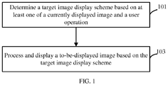
- FIG. 1 is a flow chart of a method for controlling image display in accordance with an embodiment of the present disclosure.
- the method is applied in a terminal.
- the terminal may be a mobile phone, a tablet computer, a personal digital assistant, a handheld game player, or other.
- the method may include the follows.
- a target image display scheme is determined based on at least one of a currently displayed image and a user operation. That is, the target image display scheme may be determined based on the currently displayed image, or based on the user operation, or based on the currently displayed image and the user operation.
- the target image display scheme contains one or more parameters related to image display effects.
- the image display effects may be that an image is displayed with a high resolution, images are refreshed quickly, and so on.
- one or more parameters contained in each image display scheme may be preset based on fidelity optimized signal scaling (FOSS) technology.
- One or more parameters contained in each display scheme may include a color value, a transparency value, a contrast value, a gray value, a refresh rate, and so on.
- one or more parameters contained in each image display scheme may be preset based on content adaptive brightness control (CABC) technology.
- One or more parameters contained in each display scheme may include a color value, a transparency value, a gray value, a brightness of backlight, and so on.
- determining the target image display scheme based on the currently displayed image may include the follows.
- the target image display scheme is determined based on property information of the currently displayed image and a relationship between image property information and image display schemes.
- the property information of the currently displayed image may include a color value, a transparency value, a brightness value, a gray value, and so on.
- the relationship between image property information and image display schemes may be that each image display scheme corresponds to one or more property ranges. For example, each image display scheme corresponds to a color value range, or corresponds to a color value range and a transparency value range.
- the image display scheme is determined to be the target image display scheme.
- the image display scheme is determined to be the target image display scheme.
- the image display scheme is determined to be the target image display scheme.
- the target image display scheme is determined based on the property information of the currently displayed image, thus different scenes may be displayed by different image display schemes to provide better display effects.
- determining the target image display scheme based on the user operation may include the follows.
- the target image display scheme is determined based on the type of the user operation and a relationship between types of user operation and image display schemes.
- the user operation may be an operation of switching images in a high speed and an operation of switching images in a low speed. That is, the image display scheme determined when switching images quickly is different from that determined when switching images slowly. For example, as illustrated in FIGS.
- the user operation may be an operation of sliding from a start point 202 at a side of a screen 201 toward an end point 203 at an opposite side of the screen 201 slowly, or may be an operation of clicking a fast forward button 207 quickly to move from a first position 204 of a progress bar 206 to a second position 205, and the present disclosure is not limited thereto.
- the relationship between types of user operation and image display schemes may be that different types of user operation corresponds to different image display schemes.
- the target image display scheme is determined based on the relationship between types of user operation and image display schemes. For example, when the user operation is the operation of switching images quickly, it may indicate that a user just wants to browse images quickly rather than viewing each image carefully, so an image display scheme which may cause power consumption to be low may be selected. When the user operation is the operation of switching images slowly, it may indicate that the user wants to view each image carefully, so an image display scheme which can provide better display effects may be selected.
- determining the target image display scheme based on the currently displayed image and the user operation may include the follows.
- a first image display scheme is determined based on property information of the currently displayed image and a relationship between image property information and image display schemes, and a power saving level corresponding to the first image display scheme is determined based on a relationship between power saving levels and image display schemes.
- a higher power saving level indicates less power consumption.
- a second image display scheme is determined based on the type of the user operation and a relationship between types of user operation and image display schemes, and a power saving level corresponding to the second image display scheme is determined based on the relationship between power saving levels and image display schemes.
- the first image display scheme is then determined to be the target image display scheme when the power saving level corresponding to the first image display scheme is higher than that corresponding to the second image display scheme
- the second image display scheme is then determined to be the target image scheme when the power saving level corresponding to the second image display scheme is higher than that corresponding to the first image display scheme.
- the first image display scheme or the second image display scheme may be selected.
- a corresponding power saving level is also determined.
- the target image display scheme is displayed further based on the power saving levels.
- an image display scheme with lower power consumption can be employed to save power.
- the target image display scheme is determined every a preset period, and by means of which, power can be further saved.
- the used image display scheme during playing of the video may be the same, so there is no need to change the image display scheme.
- power can be saved.
- various manners may be used to acquire the currently displayed image. For example, data in a frame buffer may be read via a process, and then the data is stored as a screen capture, that is, stored as the currently displayed image.
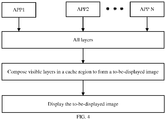
- FIGS. 4-5 illustrate image generation and image display in accordance with an embodiment of the present disclosure.
- each application may include one or more layers.
- An application executes a layer drawing operation (that is, drawing images on layers) based on a corresponding installation package. After the layer drawing operation, the application transmits the layers to the layer composition unit to perform the layer composition operation.
- a layer drawing operation that is, drawing images on layers
- all layers constitute a layer list defined as ListAll.
- the layer composition unit selects the visible layers to form a visible layer list defined as DisplayList.
- the layer composition unit selects an unoccupied frame buffer (FB) from three FBs which are used in turn, and in the unoccupied FB the layers of the DisplayList are laminated together to obtain a to-be-displayed image based on application configuration information.
- the application configuration information may include which layer is on the bottom, which layer is on the top, which region is visible, which region is transparent, and so on.
- the to-be-displayed image is transmitted to a display hardware (including a display controller and the display screen) to display the to-be-displayed image.
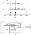
- Vsync display refresh mechanism is displayed.
- the Vsync display refresh mechanism is that in a whole display process, Vsync signals are inserted and transmitted to a processor (CPU) via the display controller to generate Vsync interrupts, such that each layer drawing operation and each layer composition operation are needed to be performed according to the Vsync signals, whereby key operations of the whole display process belong to a Vsync management mechanism.
- the frequency of the Vsync signal is 60Hz. As illustrated in FIG.
- Vsync1 a first Vsync signal
- Vsync2 a second Vsync signal
- the CPU transmits the Vsync2 to the layer composition unit, and the layer composition unit begins to execute the layer composition operation to generate a to-be-displayed image.
- Vsync3 After a third Vsync signal (Vsync3) reaches the CPU, the refresh operation is executed to display the to-be-displayed image on the display screen.
- Vsync3 the frequencies of the Vsync signals received by the currently running application, the layer composition unit, and the display screen are the same.
- the rates may include a drawing frame rate, a composition frame rate, and a refresh rate.
- the drawing frame rate is a frame rate to perform a layer drawing operation, and it may indicate layer frames are drawn in a unit time (for example, one second).
- the drawing frame rate may include a drawing frame rate of an application and a drawing frame rate of a layer.
- Each application may include multiple layers.
- a video player may include three layers: a layer for displaying video content which is defined as U1 and two layers of SurfaceView type, one is for displaying bullet content which is defined as U2, and the other is for displaying user interface widgets (for example, a progress bar, a volume control bar, various control buttons, and so on) and broadcasts which is defined as U3.
- the drawing frame rate of an application is the number of times that the application executes the layer drawing operation in a unit time. When one layer drawing operation is performed, one or more layers may be drawn.
- the composition frame rate is a frame rate in which the layers drawn by an application is composed as a to-be-displayed image, and the composition frame rate can be understood to be the number of image frames composed in a time unit.
- the terminal will refresh the displayed image in the refresh rate of 60Hz.
- a to-be-displayed image is processed and displayed based on the target image display scheme.
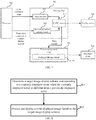
- FIG. 6 a display mechanism may be illustrated in FIG. 6 .
- Data for forming a to-be-displayed image is transmitted by a processor 510 to an image analyzer 521 of a driving chip 520 of a display screen 530, and the one or more parameters contained in the target display scheme is also transmitted by the processor 510 to a first algorithm setting circuit 522.
- the image analyzer 521 analyzes the data received from the processor 510 to obtain property information of the to-be-displayed image.
- the property information of the to-be-displayed image is transmitted to a FOSS circuit 523.
- the FOSS circuit 523 employs a preset algorithm to adjust the property information of the to-be-displayed image based on the one or more parameters contained in the target displayed scheme. For example, gray values of some pixel points are adjusted.
- the processed to-be-displayed image is then transmitted to the display screen 530 for display.
- the display screen 530 may be an organic light emitting display (OLED) screen, an active matrix/organic light emitting diode screen, or the like.
- a display mechanism may be illustrated in FIG. 7 .
- Data for forming a to-be-displayed image is transmitted by the processor 510 to an image analyzer 541 of a driving chip 540 of the display screen 530, and the one or more parameters contained in the target display scheme is also transmitted by the processor 510 to a second algorithm setting circuit 542.
- the image analyzer 541 analyzes the data received from the processor 510 to obtain property information of the to-be-displayed image.
- the property information of the to-be-displayed image is transmitted to a CABC circuit 543.
- the CABC circuit 543 employs a preset algorithm to adjust the property information of the to-be-displayed image based on the one or more parameters contained in the target displayed scheme. For example, gray values of some pixel points are adjusted. Furthermore, the CABC circuit 543 outputs pulse signals to a power management chip 550. The power management chip 550 controls a backlight driving circuit 551 to output waves based on a preset algorithm. The waves are used to control brightness of backlight diodes 560 of the display screen 530. For example, the CABC circuit 543 increases the gray value of the to-be-displayed image by 30%, and the power management chip 550 decreases the brightness of backlight by 30%. Thus, the display effects are not affected, and power saving is realized.
- FIG. 8 is a flow chart of a method for controlling image display in accordance with another embodiment of the present disclosure. The method may include the follows.
- a target image display scheme corresponding to a currently displayed scene is determined when the currently displayed scene is different from a previously displayed scene.
- the target image display scheme contains one or more parameters related to image display effects.
- the currently displayed scene may be a video scene, a game scene, a chatting scene, or other.
- the target image display scheme may be determined based on property information of a currently displayed image and a relationship between image property information and image display schemes, or based on the type of a user operation and a relationship between types of user operation and image display schemes, or based on both of the property information of the currently displayed image and the type of the user operation, which are illustrated in FIG. 1 and will not be repeated herein.
- a to-be-displayed image is processed and displayed based on the target image display scheme.
- the process at block 803 may correspond to the process at block 103.
- FIG. 9 is a block diagram of a terminal in accordance with an embodiment of the present disclosure.
- the terminal may include a determining unit 901 and a processing unit 903.
- the determining unit 901 may be configured to determine a target image display scheme based on at least one of a currently displayed image and a user operation. That is, the target image display scheme may be determined based on the currently displayed image, or based on the user operation, or based on the currently displayed image and the user operation.
- the target image display scheme contains one or more parameters related to image display effects.
- one or more parameters contained in each image display scheme may be preset based on FOSS technology.
- One or more parameters contained in each display scheme may include a color value, a transparency value, a contrast value, a gray value, a refresh rate, and so on.
- one or more parameters contained in each image display scheme may be preset based on CABC technology.
- One or more parameters contained in each display scheme may include a gray value, a transparency value, a brightness of backlight, and so on.
- determining the target image display scheme based on the currently displayed image may include the follows.
- the target image display scheme is determined based on property information of the currently displayed image and a relationship between image property information and image display schemes.
- the property information of the currently displayed image may include a color value, a transparency value, a brightness value, a gray value, and so on.
- the relationship between image property information and image display schemes may be that each image display scheme corresponds to one or more property ranges. For example, each image display scheme corresponds to a color value range, or corresponds to a color value range and a transparency value range.
- the image display scheme is determined to be the target image display scheme.
- the image display scheme is determined to be the target image display scheme.
- the image display scheme is determined to be the target image display scheme.
- the target image display scheme is determined based on the property information of the currently displayed image, thus different scenes may be displayed by different image display schemes to provide better display effects.
- determining the target image display scheme based on the user operation may include the follows.
- the target image display scheme is determined based on the type of the user operation and a relationship between types of user operation and image display schemes.
- the user operation may be an operation of switching images in a high speed and an operation of switching images in a low speed. That is, the image display scheme determined when switching images quickly is different from that determined when switching images slowly.
- the relationship between types of user operation and image display schemes may be that different types of user operation corresponds to different image display schemes.
- the target image display scheme is determined based on the relationship between types of user operation and image display schemes. For example, when the user operation is the operation of switching images quickly, it may indicate that a user just wants to browse images quickly rather than viewing each image carefully, so an image display scheme which may cause power consumption to be low may be selected. When the user operation is the operation of switching images slowly, it may indicate that the user wants to view each image carefully, so an image display scheme which can provide better display effects may be selected.
- determining the target image display scheme based on the currently displayed image and the user operation may include the follows.
- a first image display scheme is determined based on property information of the currently displayed image and a relationship between image property information and image display schemes, and a power saving level corresponding to the first image display scheme is determined based on a relationship between power saving levels and image display schemes.
- a higher power saving level indicates less power consumption.
- a second image display scheme is determined based on the type of the user operation and a relationship between types of user operation and image display schemes, and a power saving level corresponding to the second image display scheme is determined based on the relationship between power saving levels and image display schemes.
- the first image display scheme is then determined to be the target image display scheme when the power saving level corresponding to the first image display scheme is higher than that corresponding to the second image display scheme
- the second image display scheme is then determined to be the target image scheme when the power saving level corresponding to the second image display scheme is higher than that corresponding to the first image display scheme.
- the first image display scheme or the second image display scheme may be selected.
- a corresponding power saving level is also determined.
- the target image display scheme is displayed further based on the power saving levels.
- an image display scheme with lower power consumption can be employed to save power.
- the target image display scheme is determined every a preset period, and by means of which, power can be further saved.
- the used image display scheme during playing of the video may be the same, so there is no need to change the image display scheme.
- power can be saved.
- the determining unit 901 may be configured to determine a target image display scheme corresponding to a currently displayed scene when the currently displayed scene is different from a previously displayed scene.
- the currently displayed scene is different from the previously displayed scene, it indicates that the image display scheme may need to be changed.
- image display effects may be much better.
- the processing unit 903 may be configured to process and display a to-be-displayed image based on the target image display scheme.
- each unit may be an application specific integrated circuit (ASIC), a single circuit, a processor (shared, specific, or chipset) for executing one or more software or hardware procedures in a memory, a combined logic circuit, and/or other appropriate assembly for realizing the above function.
- ASIC application specific integrated circuit
- processor shared, specific, or chipset
- FIG. 10 is a structural view of a terminal in accordance with an embodiment of the present disclosure.
- a terminal 1000 may include a memory 1001 and a processor 1003.
- the memory 1001 stores computer-readable program codes.
- the memory 1001 may be a random access memory, a nonvolatile memory, a disk, and so on.
- the processor 1003 may be configured to invoke the computer-readable program codes to perform the method illustrated by FIG. 1 or the method illustrated by FIG. 8 , which will not be repeated herein.
- the terminal 1000 may further include a peripheral interface 1005, a radio frequency (RF) circuit 1007, an audio circuit 1009, a speaker 1011, a power management chip 1013, an input/output sub-system 1015, a touch screen 1017, an input/control device 1019, an external port 1021, and so on.
- RF radio frequency
- the input/output sub-system 1015 can couple the touch screen 1017 and the input/control device 1019 to the peripheral interface 1005.
- the input/output sub-system 1015 may include a display controller 1151 and an input controller 1153 which is configured to control the input/control device 1019.
- the input controller 1153 can receive electrical signals from or transmit electrical signals to the input/control device 1019.
- the input/control device 1019 may include physical buttons, a sliding switch, a joy stick, and so on.
- the input controller 1153 may be coupled to a keyboard, a universal serial bus interface, a mouse, and so on.
- the touch screen 1017 may be a capacitance-type touch screen, a resistance-type touch screen, a surface acoustic wave touch screen, and so on.
- the display controller 1151 may receive electrical signals from or transmit electrical signals to the touch screen 1017.
- the RF circuit 1007 may be configured to establish communication between the terminal 1000 and a network.
- the audio circuit 1009 may be configured to receive audio data from the peripheral interface 1005, convert the audio data into electrical signals, and transmit the electrical signals to the speaker 1011.
Landscapes
- Engineering & Computer Science (AREA)
- Physics & Mathematics (AREA)
- Computer Hardware Design (AREA)
- General Physics & Mathematics (AREA)
- Theoretical Computer Science (AREA)
- Computer Networks & Wireless Communication (AREA)
- Signal Processing (AREA)
- Human Computer Interaction (AREA)
- Controls And Circuits For Display Device (AREA)
- Control Of Indicators Other Than Cathode Ray Tubes (AREA)
Abstract
Description
- The present disclosure relates to terminals, and particularly to a method for controlling image display and a terminal.
- Presently, terminals such as smart phones may include various applications, thus various scenes (a game scene, a chatting scene, and so on) may be displayed on the terminals. The terminals may adopt a fixed image display scheme which contains one or more parameters related to display effects to display different scenes, and by means of which, it may be difficult to maintain a balance between power saving and good display effects.
- Embodiments of the present disclosure provide a method for controlling image display and a terminal, and by means of which image display effects may be improved.
- In a first aspect, a method for controlling image display is provided. The method may include: determining a target image display scheme based on at least one of a currently displayed image and a user operation, and processing and displaying a to-be-displayed image based on the target image display scheme. The target image display scheme contains at least one parameter related to image display effects.
- In a second aspect, a terminal is provided. The terminal may include a memory and a processor. The memory is configured to store computer-readable program codes. The processor is configured to invoke the computer-readable program codes to perform following acts: determining a target image display scheme corresponding to a currently displayed scene when the currently displayed scene is different from a previously displayed scene, and processing and displaying a to-be-displayed image based on the target image display scheme. The target image display scheme contains at least one parameter related to image display effects.
- In a third aspect, a terminal is provided. The terminal may include a memory and a processor. The memory is configured to store computer-readable program codes. The processor is configured to invoke the computer-readable program codes to perform following acts: determining a target image display scheme based on at least one of a currently displayed image and a user operation, and processing and displaying a to-be-displayed image based on the target image display scheme. The target image display scheme contains at least one parameter related to image display effects.
- In the present disclosure, the target image display scheme is firstly determined, and then a to-be-displayed image is processed and displayed based on the target image display scheme, thus image display effects can be improved.
- In order to illustrate the technical solutions of the embodiments of the present disclosure more clearly, the drawings used in the description of the embodiments will be briefly described, it will be apparent that the drawings described in the following are embodiments of the present disclosure, and it will be apparent to those skilled in the art that other drawings can be obtained from the drawings without any creative work.
-
FIG. 1 is a method for controlling image display in accordance with an embodiment of the present disclosure. -
FIG. 2 is a schematic view showing a user operation in accordance with an embodiment of the present disclosure. -
FIG. 3 is a schematic view showing a user operation in accordance with another embodiment of the present disclosure. -
FIG. 4 is a schematic view showing a display process in accordance with an embodiment of the present disclosure. -
FIG. 5 is a schematic view showing a Vsync display refresh mechanism in accordance with an embodiment of the present disclosure. -
FIG. 6 is a display mechanism based on fidelity optimized signal scaling (FOSS) technology in accordance with an embodiment of the present disclosure. -
FIG. 7 is a displayed mechanism based on content adaptive brightness control (CABC) technology in accordance with an embodiment of the present disclosure. -
FIG. 8 is a method for controlling image display in accordance with another embodiment of the present disclosure. -
FIG. 9 is a block diagram of a terminal in accordance with an embodiment of the present disclosure. -
FIG. 10 is a structural view of a terminal in accordance with an embodiment of the present disclosure. - In order to illustrate the technical solutions of the present disclosure or the related art more clearly, a brief description of the accompanying drawings used herein is given below. Obviously, the drawings listed below are only examples, and a person skilled in the art should be noted that, other drawings can also be obtained on the basis of these exemplary drawings without creative work.
- In the following description, numerous specific details are set forth in order to facilitate a thorough understanding of the present disclosure, however, the present disclosure can be practiced otherwise than as specifically described herein, and therefore, the scope of the present disclosure is not to be limited by the specific embodiments disclosed below.
-
FIG. 1 is a flow chart of a method for controlling image display in accordance with an embodiment of the present disclosure. The method is applied in a terminal. The terminal may be a mobile phone, a tablet computer, a personal digital assistant, a handheld game player, or other. The method may include the follows. - At
block 101, a target image display scheme is determined based on at least one of a currently displayed image and a user operation. That is, the target image display scheme may be determined based on the currently displayed image, or based on the user operation, or based on the currently displayed image and the user operation. The target image display scheme contains one or more parameters related to image display effects. The image display effects may be that an image is displayed with a high resolution, images are refreshed quickly, and so on. - In an implementation, one or more parameters contained in each image display scheme may be preset based on fidelity optimized signal scaling (FOSS) technology. One or more parameters contained in each display scheme may include a color value, a transparency value, a contrast value, a gray value, a refresh rate, and so on.
- In at least one alternative implantation, one or more parameters contained in each image display scheme may be preset based on content adaptive brightness control (CABC) technology. One or more parameters contained in each display scheme may include a color value, a transparency value, a gray value, a brightness of backlight, and so on.
- In an implementation, determining the target image display scheme based on the currently displayed image may include the follows. The target image display scheme is determined based on property information of the currently displayed image and a relationship between image property information and image display schemes. The property information of the currently displayed image may include a color value, a transparency value, a brightness value, a gray value, and so on. The relationship between image property information and image display schemes may be that each image display scheme corresponds to one or more property ranges. For example, each image display scheme corresponds to a color value range, or corresponds to a color value range and a transparency value range. When the property information of the currently displayed image falls within a property range corresponding to an image display scheme, the image display scheme is determined to be the target image display scheme. For example, when the color value of the currently displayed image falls within a color value range corresponding to an image display scheme, the image display scheme is determined to be the target image display scheme. For another example, when the color value and the transparency value of the currently displayed image respectively falls within a color value range and a transparency value range corresponding to an image display scheme, the image display scheme is determined to be the target image display scheme.
- In the implementation, the target image display scheme is determined based on the property information of the currently displayed image, thus different scenes may be displayed by different image display schemes to provide better display effects.
- In at least one implementation, determining the target image display scheme based on the user operation may include the follows. The target image display scheme is determined based on the type of the user operation and a relationship between types of user operation and image display schemes. The user operation may be an operation of switching images in a high speed and an operation of switching images in a low speed. That is, the image display scheme determined when switching images quickly is different from that determined when switching images slowly. For example, as illustrated in
FIGS. 2-3 , the user operation may be an operation of sliding from astart point 202 at a side of ascreen 201 toward anend point 203 at an opposite side of thescreen 201 slowly, or may be an operation of clicking a fastforward button 207 quickly to move from afirst position 204 of aprogress bar 206 to asecond position 205, and the present disclosure is not limited thereto. - In this implementation, the relationship between types of user operation and image display schemes may be that different types of user operation corresponds to different image display schemes. When the type of the user operation is determined, the target image display scheme is determined based on the relationship between types of user operation and image display schemes. For example, when the user operation is the operation of switching images quickly, it may indicate that a user just wants to browse images quickly rather than viewing each image carefully, so an image display scheme which may cause power consumption to be low may be selected. When the user operation is the operation of switching images slowly, it may indicate that the user wants to view each image carefully, so an image display scheme which can provide better display effects may be selected.
- In at least one alternative implementation, determining the target image display scheme based on the currently displayed image and the user operation may include the follows. A first image display scheme is determined based on property information of the currently displayed image and a relationship between image property information and image display schemes, and a power saving level corresponding to the first image display scheme is determined based on a relationship between power saving levels and image display schemes. A higher power saving level indicates less power consumption. Furthermore, a second image display scheme is determined based on the type of the user operation and a relationship between types of user operation and image display schemes, and a power saving level corresponding to the second image display scheme is determined based on the relationship between power saving levels and image display schemes. The first image display scheme is then determined to be the target image display scheme when the power saving level corresponding to the first image display scheme is higher than that corresponding to the second image display scheme, and the second image display scheme is then determined to be the target image scheme when the power saving level corresponding to the second image display scheme is higher than that corresponding to the first image display scheme. Certainly, when the power saving level corresponding to the first image display scheme is the same as that corresponding to the second image display scheme, the first image display scheme or the second image display scheme may be selected.
- In this implementation, when an image display scheme is determined, a corresponding power saving level is also determined. The target image display scheme is displayed further based on the power saving levels. Thus, an image display scheme with lower power consumption can be employed to save power.
- In an implementation, the target image display scheme is determined every a preset period, and by means of which, power can be further saved. For example, when playing a video, the used image display scheme during playing of the video may be the same, so there is no need to change the image display scheme. Thus, by means of determining the target image display scheme every the preset period, power can be saved.
- In an implementation, various manners may be used to acquire the currently displayed image. For example, data in a frame buffer may be read via a process, and then the data is stored as a screen capture, that is, stored as the currently displayed image.
-
FIGS. 4-5 illustrate image generation and image display in accordance with an embodiment of the present disclosure. - Referring to
FIG. 4 , each application may include one or more layers. An application executes a layer drawing operation (that is, drawing images on layers) based on a corresponding installation package. After the layer drawing operation, the application transmits the layers to the layer composition unit to perform the layer composition operation. - In the framework layer, all layers (including visible layers and invisible layers) constitute a layer list defined as ListAll. The layer composition unit selects the visible layers to form a visible layer list defined as DisplayList. The layer composition unit selects an unoccupied frame buffer (FB) from three FBs which are used in turn, and in the unoccupied FB the layers of the DisplayList are laminated together to obtain a to-be-displayed image based on application configuration information. The application configuration information may include which layer is on the bottom, which layer is on the top, which region is visible, which region is transparent, and so on.
- Finally, in a kernel layer, the to-be-displayed image is transmitted to a display hardware (including a display controller and the display screen) to display the to-be-displayed image.
- Referring to
FIG. 5 , a Vsync display refresh mechanism is displayed. The Vsync display refresh mechanism is that in a whole display process, Vsync signals are inserted and transmitted to a processor (CPU) via the display controller to generate Vsync interrupts, such that each layer drawing operation and each layer composition operation are needed to be performed according to the Vsync signals, whereby key operations of the whole display process belong to a Vsync management mechanism. The frequency of the Vsync signal is 60Hz. As illustrated inFIG. 4 , it is assumed that the period of the Vsync signal is T, without consideration of transmission delay, after a first Vsync signal (Vsync1) reaches the CPU, the CPU transmits the Vsync1 to the currently running application. The currently running application responds to a user operation such as a sliding operation to begin the layer drawing operation. After the layer drawing operation, multiple layers are obtained. After a second Vsync signal (Vsync2) reaches the CPU, the CPU transmits the Vsync2 to the layer composition unit, and the layer composition unit begins to execute the layer composition operation to generate a to-be-displayed image. After a third Vsync signal (Vsync3) reaches the CPU, the refresh operation is executed to display the to-be-displayed image on the display screen. For the above description, it can be known that the frequencies of the Vsync signals received by the currently running application, the layer composition unit, and the display screen are the same. - In the process from generating an image to displaying an image, three rates may be employed. The rates may include a drawing frame rate, a composition frame rate, and a refresh rate.
- The drawing frame rate is a frame rate to perform a layer drawing operation, and it may indicate layer frames are drawn in a unit time (for example, one second). The drawing frame rate may include a drawing frame rate of an application and a drawing frame rate of a layer. Each application may include multiple layers. For example, a video player may include three layers: a layer for displaying video content which is defined as U1 and two layers of SurfaceView type, one is for displaying bullet content which is defined as U2, and the other is for displaying user interface widgets (for example, a progress bar, a volume control bar, various control buttons, and so on) and broadcasts which is defined as U3. The drawing frame rate of an application is the number of times that the application executes the layer drawing operation in a unit time. When one layer drawing operation is performed, one or more layers may be drawn.
- The composition frame rate is a frame rate in which the layers drawn by an application is composed as a to-be-displayed image, and the composition frame rate can be understood to be the number of image frames composed in a time unit.
- Generally, the terminal will refresh the displayed image in the refresh rate of 60Hz.
- At
block 103, a to-be-displayed image is processed and displayed based on the target image display scheme. - In an implantation, when one or more parameters contained in each image display scheme is preset based on FOSS technology, a display mechanism may be illustrated in
FIG. 6 . Data for forming a to-be-displayed image is transmitted by aprocessor 510 to animage analyzer 521 of adriving chip 520 of adisplay screen 530, and the one or more parameters contained in the target display scheme is also transmitted by theprocessor 510 to a firstalgorithm setting circuit 522. Theimage analyzer 521 analyzes the data received from theprocessor 510 to obtain property information of the to-be-displayed image. The property information of the to-be-displayed image is transmitted to aFOSS circuit 523. TheFOSS circuit 523 employs a preset algorithm to adjust the property information of the to-be-displayed image based on the one or more parameters contained in the target displayed scheme. For example, gray values of some pixel points are adjusted. The processed to-be-displayed image is then transmitted to thedisplay screen 530 for display. Thedisplay screen 530 may be an organic light emitting display (OLED) screen, an active matrix/organic light emitting diode screen, or the like. - In at least one alternative implementation, when one or more parameters contained in each image display scheme is preset based on CABC technology, a display mechanism may be illustrated in
FIG. 7 . Data for forming a to-be-displayed image is transmitted by theprocessor 510 to animage analyzer 541 of adriving chip 540 of thedisplay screen 530, and the one or more parameters contained in the target display scheme is also transmitted by theprocessor 510 to a secondalgorithm setting circuit 542. Theimage analyzer 541 analyzes the data received from theprocessor 510 to obtain property information of the to-be-displayed image. The property information of the to-be-displayed image is transmitted to aCABC circuit 543. TheCABC circuit 543 employs a preset algorithm to adjust the property information of the to-be-displayed image based on the one or more parameters contained in the target displayed scheme. For example, gray values of some pixel points are adjusted. Furthermore, theCABC circuit 543 outputs pulse signals to apower management chip 550. Thepower management chip 550 controls abacklight driving circuit 551 to output waves based on a preset algorithm. The waves are used to control brightness ofbacklight diodes 560 of thedisplay screen 530. For example, theCABC circuit 543 increases the gray value of the to-be-displayed image by 30%, and thepower management chip 550 decreases the brightness of backlight by 30%. Thus, the display effects are not affected, and power saving is realized. -
FIG. 8 is a flow chart of a method for controlling image display in accordance with another embodiment of the present disclosure. The method may include the follows. - At
block 801, a target image display scheme corresponding to a currently displayed scene is determined when the currently displayed scene is different from a previously displayed scene. The target image display scheme contains one or more parameters related to image display effects. - Various manners can be employed to determine the currently displayed scene. For example, one or more process identifiers of an application can be used to determine the currently display scene, and the present disclosure is not limited thereto. The currently displayed scene may be a video scene, a game scene, a chatting scene, or other.
- In the embodiment, the target image display scheme may be determined based on property information of a currently displayed image and a relationship between image property information and image display schemes, or based on the type of a user operation and a relationship between types of user operation and image display schemes, or based on both of the property information of the currently displayed image and the type of the user operation, which are illustrated in
FIG. 1 and will not be repeated herein. - At
block 803, a to-be-displayed image is processed and displayed based on the target image display scheme. The process atblock 803 may correspond to the process atblock 103. - In the embodiment, when the currently displayed scene is different from the previously displayed scene, it indicates that the image display scheme may need to be changed. Thus, adopting the target image display scheme when the displayed scene is changed, image display effects may be much better.
-
FIG. 9 is a block diagram of a terminal in accordance with an embodiment of the present disclosure. The terminal may include a determiningunit 901 and aprocessing unit 903. - The determining
unit 901 may be configured to determine a target image display scheme based on at least one of a currently displayed image and a user operation. That is, the target image display scheme may be determined based on the currently displayed image, or based on the user operation, or based on the currently displayed image and the user operation. The target image display scheme contains one or more parameters related to image display effects. - In an implementation, one or more parameters contained in each image display scheme may be preset based on FOSS technology. One or more parameters contained in each display scheme may include a color value, a transparency value, a contrast value, a gray value, a refresh rate, and so on.
- In at least one alternative implantation, one or more parameters contained in each image display scheme may be preset based on CABC technology. One or more parameters contained in each display scheme may include a gray value, a transparency value, a brightness of backlight, and so on.
- In an implementation, determining the target image display scheme based on the currently displayed image may include the follows. The target image display scheme is determined based on property information of the currently displayed image and a relationship between image property information and image display schemes. The property information of the currently displayed image may include a color value, a transparency value, a brightness value, a gray value, and so on. The relationship between image property information and image display schemes may be that each image display scheme corresponds to one or more property ranges. For example, each image display scheme corresponds to a color value range, or corresponds to a color value range and a transparency value range. When the property information of the currently displayed image falls within a property range corresponding to an image display scheme, the image display scheme is determined to be the target image display scheme. For example, when the color value of the currently displayed image falls within a color value range corresponding to an image display scheme, the image display scheme is determined to be the target image display scheme. For another example, when the color value and the transparency value of the currently displayed image respectively falls within a color value range and a transparency value range corresponding to an image display scheme, the image display scheme is determined to be the target image display scheme.
- In the implementation, the target image display scheme is determined based on the property information of the currently displayed image, thus different scenes may be displayed by different image display schemes to provide better display effects.
- In at least one implementation, determining the target image display scheme based on the user operation may include the follows. The target image display scheme is determined based on the type of the user operation and a relationship between types of user operation and image display schemes. The user operation may be an operation of switching images in a high speed and an operation of switching images in a low speed. That is, the image display scheme determined when switching images quickly is different from that determined when switching images slowly.
- In this implementation, the relationship between types of user operation and image display schemes may be that different types of user operation corresponds to different image display schemes. When the type of the user operation is determined, the target image display scheme is determined based on the relationship between types of user operation and image display schemes. For example, when the user operation is the operation of switching images quickly, it may indicate that a user just wants to browse images quickly rather than viewing each image carefully, so an image display scheme which may cause power consumption to be low may be selected. When the user operation is the operation of switching images slowly, it may indicate that the user wants to view each image carefully, so an image display scheme which can provide better display effects may be selected.
- In at least one alternative implementation, determining the target image display scheme based on the currently displayed image and the user operation may include the follows. A first image display scheme is determined based on property information of the currently displayed image and a relationship between image property information and image display schemes, and a power saving level corresponding to the first image display scheme is determined based on a relationship between power saving levels and image display schemes. A higher power saving level indicates less power consumption. Furthermore, a second image display scheme is determined based on the type of the user operation and a relationship between types of user operation and image display schemes, and a power saving level corresponding to the second image display scheme is determined based on the relationship between power saving levels and image display schemes. The first image display scheme is then determined to be the target image display scheme when the power saving level corresponding to the first image display scheme is higher than that corresponding to the second image display scheme, and the second image display scheme is then determined to be the target image scheme when the power saving level corresponding to the second image display scheme is higher than that corresponding to the first image display scheme. Certainly, when the power saving level corresponding to the first image display scheme is the same as that corresponding to the second image display scheme, the first image display scheme or the second image display scheme may be selected.
- In this implementation, when an image display scheme is determined, a corresponding power saving level is also determined. The target image display scheme is displayed further based on the power saving levels. Thus, an image display scheme with lower power consumption can be employed to save power.
- In an implementation, the target image display scheme is determined every a preset period, and by means of which, power can be further saved. For example, when playing a video, the used image display scheme during playing of the video may be the same, so there is no need to change the image display scheme. Thus, by means of determining the target image display scheme every the preset period, power can be saved.
- In at least one alternative embodiment, the determining
unit 901 may be configured to determine a target image display scheme corresponding to a currently displayed scene when the currently displayed scene is different from a previously displayed scene. When the currently displayed scene is different from the previously displayed scene, it indicates that the image display scheme may need to be changed. Thus, adopting the target image display scheme when the displayed scene is changed, image display effects may be much better. - The
processing unit 903 may be configured to process and display a to-be-displayed image based on the target image display scheme. - It shall be noted that the terminal described in the device embodiment of the present disclosure is illustrated in the form of functional units. The term "unit" used herein shall be taken in the broadest possible sense. Objects for realizing the function of each unit may be an application specific integrated circuit (ASIC), a single circuit, a processor (shared, specific, or chipset) for executing one or more software or hardware procedures in a memory, a combined logic circuit, and/or other appropriate assembly for realizing the above function.
-
FIG. 10 is a structural view of a terminal in accordance with an embodiment of the present disclosure. A terminal 1000 may include amemory 1001 and aprocessor 1003. Thememory 1001 stores computer-readable program codes. Thememory 1001 may be a random access memory, a nonvolatile memory, a disk, and so on. Theprocessor 1003 may be configured to invoke the computer-readable program codes to perform the method illustrated byFIG. 1 or the method illustrated byFIG. 8 , which will not be repeated herein. - The terminal 1000 may further include a
peripheral interface 1005, a radio frequency (RF)circuit 1007, anaudio circuit 1009, aspeaker 1011, apower management chip 1013, an input/output sub-system 1015, atouch screen 1017, an input/control device 1019, anexternal port 1021, and so on. - The input/
output sub-system 1015 can couple thetouch screen 1017 and the input/control device 1019 to theperipheral interface 1005. The input/output sub-system 1015 may include adisplay controller 1151 and aninput controller 1153 which is configured to control the input/control device 1019. Theinput controller 1153 can receive electrical signals from or transmit electrical signals to the input/control device 1019. The input/control device 1019 may include physical buttons, a sliding switch, a joy stick, and so on. Theinput controller 1153 may be coupled to a keyboard, a universal serial bus interface, a mouse, and so on. - The
touch screen 1017 may be a capacitance-type touch screen, a resistance-type touch screen, a surface acoustic wave touch screen, and so on. - The
display controller 1151 may receive electrical signals from or transmit electrical signals to thetouch screen 1017. - The
RF circuit 1007 may be configured to establish communication between the terminal 1000 and a network. - The
audio circuit 1009 may be configured to receive audio data from theperipheral interface 1005, convert the audio data into electrical signals, and transmit the electrical signals to thespeaker 1011. - While the present disclosure has been described in detail above with reference to the exemplary embodiments, the scope of the present disclosure is not limited thereto. As will occur to those skilled in the art, the present disclosure is susceptible to various modifications and changes without departing from the spirit and principle of the present disclosure. Therefore, the scope of the present disclosure should be determined by the scope of the claims.
Claims (15)
- A method for controlling image display, comprising:determining a target image display scheme based on at least one of a currently displayed image and a user operation, the target image display scheme containing at least one parameter related to image display effects; andprocessing and displaying a to-be-displayed image based on the target image display scheme.
- The method of claim 1, wherein determining the target image display scheme based on at least one of the currently displayed image and the user operation comprises:determining the target image display scheme based on property information of the currently displayed image and a relationship between image property information and image display schemes.
- The method of claim 2, wherein the property information of the currently displayed image is selected from a group at least consisted by a color value and a transparency value.
- The method of claim 1, wherein determining the target image display scheme based on at least one of the currently display image and the user operation comprises:determining the target image display scheme based on the type of the user operation and a relationship between types of user operation and image display schemes.
- The method of claim 1, wherein determining the target image display scheme based on at least one of the currently display image and the user operation comprises:determining a first image display scheme based on property information of the currently displayed image and a relationship between image property information and image display schemes, and determining a power saving level corresponding to the first image display scheme based on a relationship between power saving levels and image display schemes;determining a second image display scheme based on the type of the user operation and a relationship between types of user operation and image display schemes, and determining a power saving level corresponding to the second image display scheme based on the relationship between power saving levels and image display schemes; anddetermining the first image display scheme to be the target image display scheme when the power saving level corresponding to the first image display scheme is higher than that corresponding to the second image display scheme, and determining the second image display scheme to be the target image scheme when the power saving level corresponding to the second image display scheme is higher than that corresponding to the first image display scheme.
- The method of any of claims 1-5, wherein determining the target image display scheme comprises:determining the target image display scheme every a preset period.
- The method of any of claims 1-6, wherein the target image display scheme is preset based on fidelity optimized signal scaling technology.
- A terminal, comprising:a memory configured to store computer-readable program codes; anda processor configured to invoke the computer-readable program codes to perform following acts:determining a target image display scheme corresponding to a currently displayed scene when the currently displayed scene is different from a previously displayed scene, the target image display scheme containing at least one parameter related to image display effects; andprocessing and displaying a to-be-displayed image based on the target image display scheme.
- The terminal of claim 8, wherein the processor that is configured to determine the target image display scheme corresponding to the currently displayed scene is further configured to determine the target image display scheme based on property information of a currently displayed image and a relationship between image property information and image display schemes.
- The terminal of claim 9, wherein the property information of the currently displayed image is selected from a group at least consisted by a color value and a transparency value.
- The terminal of claim 8, wherein the processor that is configured to determine the target image display scheme corresponding to the currently displayed scene is further configured to determine the target image display scheme based on the type of a user operation and a relationship between types of user operation and image display schemes.
- The terminal of claim 8, wherein the processor that is configured to determine the target image display scheme corresponding to the currently displayed scene is further configured to perform following acts:determining a first image display scheme based on property information of a currently displayed image and a relationship between image property information and image display schemes, and determining a power saving level corresponding to the first image display scheme based on a relationship between power saving levels and image display schemes;determining a second image display scheme based on the type of a user operation and a relationship between types of user operation and image display schemes, and determining a power saving level corresponding to the second image display scheme based on the relationship between power saving levels and image display schemes; anddetermining the first image display scheme to be the target image display scheme when the power saving level corresponding to the first image display scheme is higher than that corresponding to the second image display scheme, and determining the second image display scheme to be the target image scheme when the power saving level corresponding to the second image display scheme is higher than that corresponding to the first image display scheme.
- The terminal of any of claims 8-12, wherein the processor that is configured to determine the target image display scheme is further configured to determine the target image display scheme every a preset period.
- The terminal of any of claims 8-13, wherein the target image display scheme is preset based on fidelity optimized signal scaling technology.
- A terminal comprising:a memory configured to store computer-readable program codes; anda processor configured to invoke the computer-readable program codes to execute the method of any of claims 1-7.
Applications Claiming Priority (1)
| Application Number | Priority Date | Filing Date | Title |
|---|---|---|---|
| CN201710141744.9A CN106658691B (en) | 2017-03-10 | 2017-03-10 | Display control method and device and mobile terminal |
Publications (2)
| Publication Number | Publication Date |
|---|---|
| EP3373281A1 true EP3373281A1 (en) | 2018-09-12 |
| EP3373281B1 EP3373281B1 (en) | 2020-02-19 |
Family
ID=58848171
Family Applications (1)
| Application Number | Title | Priority Date | Filing Date |
|---|---|---|---|
| EP17191523.4A Active EP3373281B1 (en) | 2017-03-10 | 2017-09-18 | Method for controlling image display and terminal |
Country Status (4)
| Country | Link |
|---|---|
| US (1) | US10360833B2 (en) |
| EP (1) | EP3373281B1 (en) |
| CN (1) | CN106658691B (en) |
| WO (1) | WO2018161521A1 (en) |
Families Citing this family (10)
| Publication number | Priority date | Publication date | Assignee | Title |
|---|---|---|---|---|
| CN106658691B (en) * | 2017-03-10 | 2020-01-14 | Oppo广东移动通信有限公司 | Display control method and device and mobile terminal |
| CN108710478B (en) * | 2018-03-27 | 2021-06-08 | Oppo广东移动通信有限公司 | Display screen control method and device, storage medium and intelligent terminal |
| CN108762652B (en) * | 2018-03-27 | 2020-08-21 | Oppo广东移动通信有限公司 | Display control method and device of intelligent terminal, storage medium and intelligent terminal |
| CN109166541B (en) * | 2018-09-25 | 2021-03-02 | 深圳市爱协生科技有限公司 | A CABC method that saves power and does not distort images |
| CN109151573B (en) * | 2018-09-30 | 2021-06-15 | Oppo广东移动通信有限公司 | Video enhancement control method, device and electronic device |
| CN109151966B (en) * | 2018-10-15 | 2021-08-17 | Oppo广东移动通信有限公司 | Terminal control method, device, terminal device and storage medium |
| CN110503708A (en) * | 2019-07-03 | 2019-11-26 | 华为技术有限公司 | A kind of image processing method and electronic equipment based on vertical synchronizing signal |
| CN111933071B (en) * | 2020-08-10 | 2022-04-01 | 昆山国显光电有限公司 | Driving method and driving device of display panel |
| CN114338952B (en) * | 2020-09-30 | 2023-07-11 | 华为技术有限公司 | Image processing method based on vertical synchronous signal and electronic equipment |
| KR102786080B1 (en) * | 2022-11-14 | 2025-03-26 | 알비클라우드 주식회사 | Terminal appratus, cloud streaming service method |
Citations (2)
| Publication number | Priority date | Publication date | Assignee | Title |
|---|---|---|---|---|
| US20060250385A1 (en) * | 2005-05-04 | 2006-11-09 | Plut William J | Luminance suppression power conservation |
| US20150179123A1 (en) * | 2013-12-20 | 2015-06-25 | Amazon Technologies, Inc. | Display driving method |
Family Cites Families (13)
| Publication number | Priority date | Publication date | Assignee | Title |
|---|---|---|---|---|
| US20040252217A1 (en) * | 2003-06-12 | 2004-12-16 | Battles Amy E. | System and method for analyzing a digital image |
| BRPI0722288A2 (en) * | 2007-12-14 | 2014-04-15 | Thomson Licensing | METHOD AND APPARATUS USING PERFORMANCE FORECAST FOR CHROMICAL FAITH OPTIMIZATION OF A DISPLAY |
| TW201035741A (en) * | 2009-03-26 | 2010-10-01 | Acer Inc | Electronic device and power saving method thereof |
| CN101866208A (en) * | 2009-04-17 | 2010-10-20 | 宏碁股份有限公司 | Electronic device and power saving method thereof |
| US8854370B2 (en) * | 2011-02-16 | 2014-10-07 | Apple Inc. | Color waveform |
| CN103294158B (en) * | 2012-03-05 | 2016-12-14 | 联想(北京)有限公司 | A kind of information processing method and electronic equipment |
| CN102903337B (en) * | 2012-09-21 | 2014-09-10 | 京东方科技集团股份有限公司 | Liquid crystal display as well as control method and device thereof |
| CN103050108B (en) * | 2012-12-17 | 2015-12-02 | 华为终端有限公司 | A kind of screen backlight dynamic adjustment method and user terminal |
| CN104049710B (en) * | 2013-03-13 | 2018-12-14 | 联想(北京)有限公司 | A kind of reminding method and electronic equipment |
| US9390481B2 (en) * | 2013-05-05 | 2016-07-12 | Google Inc. | Enhancing content appearance |
| CN103631359A (en) * | 2013-11-15 | 2014-03-12 | 联想(北京)有限公司 | Information processing method and electronic equipment |
| CN104064163B (en) * | 2014-06-24 | 2017-09-01 | 中科创达软件股份有限公司 | The control method and device of a kind of brightness of display screen |
| CN106658691B (en) * | 2017-03-10 | 2020-01-14 | Oppo广东移动通信有限公司 | Display control method and device and mobile terminal |
-
2017
- 2017-03-10 CN CN201710141744.9A patent/CN106658691B/en not_active Expired - Fee Related
- 2017-09-14 WO PCT/CN2017/101739 patent/WO2018161521A1/en not_active Ceased
- 2017-09-18 EP EP17191523.4A patent/EP3373281B1/en active Active
- 2017-09-19 US US15/709,108 patent/US10360833B2/en active Active
Patent Citations (2)
| Publication number | Priority date | Publication date | Assignee | Title |
|---|---|---|---|---|
| US20060250385A1 (en) * | 2005-05-04 | 2006-11-09 | Plut William J | Luminance suppression power conservation |
| US20150179123A1 (en) * | 2013-12-20 | 2015-06-25 | Amazon Technologies, Inc. | Display driving method |
Also Published As
| Publication number | Publication date |
|---|---|
| US10360833B2 (en) | 2019-07-23 |
| EP3373281B1 (en) | 2020-02-19 |
| US20180261140A1 (en) | 2018-09-13 |
| CN106658691A (en) | 2017-05-10 |
| WO2018161521A1 (en) | 2018-09-13 |
| CN106658691B (en) | 2020-01-14 |
Similar Documents
| Publication | Publication Date | Title |
|---|---|---|
| EP3373281B1 (en) | Method for controlling image display and terminal | |
| CN106933587B (en) | A layer drawing control method, device and mobile terminal | |
| US10863213B2 (en) | Method and device for controlling frame rate of electronic device, storage medium, and electronic device | |
| CN106919358B (en) | Display control method and device of mobile terminal and mobile terminal | |
| US10565924B2 (en) | Method for determining scene currently displayed on terminal and terminal | |
| CN106933326B (en) | Method and device for dynamically adjusting energy-saving level of terminal and mobile terminal | |
| CN106933328B (en) | Method and device for controlling frame rate of mobile terminal and mobile terminal | |
| CN106919401B (en) | A method, device and mobile terminal for dynamically adjusting resolution | |
| CN106919402B (en) | A mobile terminal control method, device and mobile terminal | |
| US20200008142A1 (en) | Method for Controlling Terminal, and Terminal | |
| CN106951054B (en) | Application control method and device and mobile terminal | |
| CN106874017B (en) | Display scene identification method and device of mobile terminal and mobile terminal | |
| CN113163141A (en) | Display control method, display control device, television and computer-readable storage medium | |
| CN106896899A (en) | A kind of control method of mobile terminal Image Rendering, device and mobile terminal | |
| WO2023065807A1 (en) | Screen control method and apparatus, electronic device, and storage medium | |
| CN106933361A (en) | Display control method and device of a mobile terminal and mobile terminal | |
| US12200163B2 (en) | Electronic device with dynamic wallpaper | |
| CN106933329B (en) | A kind of method, device and mobile terminal of mobile terminal adaptive energy-saving grade | |
| CN106952611A (en) | A grayscale setting method and user terminal | |
| CN107277581A (en) | Video playing method and device and mobile terminal | |
| CN106851017B (en) | Method and device for adjusting energy-saving level of terminal and mobile terminal |
Legal Events
| Date | Code | Title | Description |
|---|---|---|---|
| PUAI | Public reference made under article 153(3) epc to a published international application that has entered the european phase |
Free format text: ORIGINAL CODE: 0009012 |
|
| STAA | Information on the status of an ep patent application or granted ep patent |
Free format text: STATUS: REQUEST FOR EXAMINATION WAS MADE |
|
| STAA | Information on the status of an ep patent application or granted ep patent |
Free format text: STATUS: EXAMINATION IS IN PROGRESS |
|
| 17P | Request for examination filed |
Effective date: 20170918 |
|
| AK | Designated contracting states |
Kind code of ref document: A1 Designated state(s): AL AT BE BG CH CY CZ DE DK EE ES FI FR GB GR HR HU IE IS IT LI LT LU LV MC MK MT NL NO PL PT RO RS SE SI SK SM TR |
|
| AX | Request for extension of the european patent |
Extension state: BA ME |
|
| 17Q | First examination report despatched |
Effective date: 20180827 |
|
| GRAP | Despatch of communication of intention to grant a patent |
Free format text: ORIGINAL CODE: EPIDOSNIGR1 |
|
| STAA | Information on the status of an ep patent application or granted ep patent |
Free format text: STATUS: GRANT OF PATENT IS INTENDED |
|
| RAP1 | Party data changed (applicant data changed or rights of an application transferred) |
Owner name: GUANGDONG OPPO MOBILE TELECOMMUNICATIONS CORP., LT |
|
| INTG | Intention to grant announced |
Effective date: 20191129 |
|
| GRAS | Grant fee paid |
Free format text: ORIGINAL CODE: EPIDOSNIGR3 |
|
| GRAA | (expected) grant |
Free format text: ORIGINAL CODE: 0009210 |
|
| STAA | Information on the status of an ep patent application or granted ep patent |
Free format text: STATUS: THE PATENT HAS BEEN GRANTED |
|
| AK | Designated contracting states |
Kind code of ref document: B1 Designated state(s): AL AT BE BG CH CY CZ DE DK EE ES FI FR GB GR HR HU IE IS IT LI LT LU LV MC MK MT NL NO PL PT RO RS SE SI SK SM TR |
|
| REG | Reference to a national code |
Ref country code: CH Ref legal event code: EP |
|
| REG | Reference to a national code |
Ref country code: DE Ref legal event code: R096 Ref document number: 602017011898 Country of ref document: DE |
|
| REG | Reference to a national code |
Ref country code: AT Ref legal event code: REF Ref document number: 1235856 Country of ref document: AT Kind code of ref document: T Effective date: 20200315 |
|
| REG | Reference to a national code |
Ref country code: IE Ref legal event code: FG4D |
|
| REG | Reference to a national code |
Ref country code: NL Ref legal event code: MP Effective date: 20200219 |
|
| PG25 | Lapsed in a contracting state [announced via postgrant information from national office to epo] |
Ref country code: FI Free format text: LAPSE BECAUSE OF FAILURE TO SUBMIT A TRANSLATION OF THE DESCRIPTION OR TO PAY THE FEE WITHIN THE PRESCRIBED TIME-LIMIT Effective date: 20200219 Ref country code: RS Free format text: LAPSE BECAUSE OF FAILURE TO SUBMIT A TRANSLATION OF THE DESCRIPTION OR TO PAY THE FEE WITHIN THE PRESCRIBED TIME-LIMIT Effective date: 20200219 Ref country code: NO Free format text: LAPSE BECAUSE OF FAILURE TO SUBMIT A TRANSLATION OF THE DESCRIPTION OR TO PAY THE FEE WITHIN THE PRESCRIBED TIME-LIMIT Effective date: 20200519 |
|
| REG | Reference to a national code |
Ref country code: LT Ref legal event code: MG4D |
|
| PG25 | Lapsed in a contracting state [announced via postgrant information from national office to epo] |
Ref country code: BG Free format text: LAPSE BECAUSE OF FAILURE TO SUBMIT A TRANSLATION OF THE DESCRIPTION OR TO PAY THE FEE WITHIN THE PRESCRIBED TIME-LIMIT Effective date: 20200519 Ref country code: GR Free format text: LAPSE BECAUSE OF FAILURE TO SUBMIT A TRANSLATION OF THE DESCRIPTION OR TO PAY THE FEE WITHIN THE PRESCRIBED TIME-LIMIT Effective date: 20200520 Ref country code: SE Free format text: LAPSE BECAUSE OF FAILURE TO SUBMIT A TRANSLATION OF THE DESCRIPTION OR TO PAY THE FEE WITHIN THE PRESCRIBED TIME-LIMIT Effective date: 20200219 Ref country code: IS Free format text: LAPSE BECAUSE OF FAILURE TO SUBMIT A TRANSLATION OF THE DESCRIPTION OR TO PAY THE FEE WITHIN THE PRESCRIBED TIME-LIMIT Effective date: 20200619 Ref country code: HR Free format text: LAPSE BECAUSE OF FAILURE TO SUBMIT A TRANSLATION OF THE DESCRIPTION OR TO PAY THE FEE WITHIN THE PRESCRIBED TIME-LIMIT Effective date: 20200219 Ref country code: LV Free format text: LAPSE BECAUSE OF FAILURE TO SUBMIT A TRANSLATION OF THE DESCRIPTION OR TO PAY THE FEE WITHIN THE PRESCRIBED TIME-LIMIT Effective date: 20200219 |
|
| PG25 | Lapsed in a contracting state [announced via postgrant information from national office to epo] |
Ref country code: NL Free format text: LAPSE BECAUSE OF FAILURE TO SUBMIT A TRANSLATION OF THE DESCRIPTION OR TO PAY THE FEE WITHIN THE PRESCRIBED TIME-LIMIT Effective date: 20200219 |
|
| PG25 | Lapsed in a contracting state [announced via postgrant information from national office to epo] |
Ref country code: CZ Free format text: LAPSE BECAUSE OF FAILURE TO SUBMIT A TRANSLATION OF THE DESCRIPTION OR TO PAY THE FEE WITHIN THE PRESCRIBED TIME-LIMIT Effective date: 20200219 Ref country code: PT Free format text: LAPSE BECAUSE OF FAILURE TO SUBMIT A TRANSLATION OF THE DESCRIPTION OR TO PAY THE FEE WITHIN THE PRESCRIBED TIME-LIMIT Effective date: 20200712 Ref country code: DK Free format text: LAPSE BECAUSE OF FAILURE TO SUBMIT A TRANSLATION OF THE DESCRIPTION OR TO PAY THE FEE WITHIN THE PRESCRIBED TIME-LIMIT Effective date: 20200219 Ref country code: EE Free format text: LAPSE BECAUSE OF FAILURE TO SUBMIT A TRANSLATION OF THE DESCRIPTION OR TO PAY THE FEE WITHIN THE PRESCRIBED TIME-LIMIT Effective date: 20200219 Ref country code: SM Free format text: LAPSE BECAUSE OF FAILURE TO SUBMIT A TRANSLATION OF THE DESCRIPTION OR TO PAY THE FEE WITHIN THE PRESCRIBED TIME-LIMIT Effective date: 20200219 Ref country code: LT Free format text: LAPSE BECAUSE OF FAILURE TO SUBMIT A TRANSLATION OF THE DESCRIPTION OR TO PAY THE FEE WITHIN THE PRESCRIBED TIME-LIMIT Effective date: 20200219 Ref country code: SK Free format text: LAPSE BECAUSE OF FAILURE TO SUBMIT A TRANSLATION OF THE DESCRIPTION OR TO PAY THE FEE WITHIN THE PRESCRIBED TIME-LIMIT Effective date: 20200219 Ref country code: RO Free format text: LAPSE BECAUSE OF FAILURE TO SUBMIT A TRANSLATION OF THE DESCRIPTION OR TO PAY THE FEE WITHIN THE PRESCRIBED TIME-LIMIT Effective date: 20200219 Ref country code: ES Free format text: LAPSE BECAUSE OF FAILURE TO SUBMIT A TRANSLATION OF THE DESCRIPTION OR TO PAY THE FEE WITHIN THE PRESCRIBED TIME-LIMIT Effective date: 20200219 |
|
| REG | Reference to a national code |
Ref country code: AT Ref legal event code: MK05 Ref document number: 1235856 Country of ref document: AT Kind code of ref document: T Effective date: 20200219 |
|
| REG | Reference to a national code |
Ref country code: DE Ref legal event code: R097 Ref document number: 602017011898 Country of ref document: DE |
|
| PLBE | No opposition filed within time limit |
Free format text: ORIGINAL CODE: 0009261 |
|
| STAA | Information on the status of an ep patent application or granted ep patent |
Free format text: STATUS: NO OPPOSITION FILED WITHIN TIME LIMIT |
|
| 26N | No opposition filed |
Effective date: 20201120 |
|
| PG25 | Lapsed in a contracting state [announced via postgrant information from national office to epo] |
Ref country code: AT Free format text: LAPSE BECAUSE OF FAILURE TO SUBMIT A TRANSLATION OF THE DESCRIPTION OR TO PAY THE FEE WITHIN THE PRESCRIBED TIME-LIMIT Effective date: 20200219 Ref country code: IT Free format text: LAPSE BECAUSE OF FAILURE TO SUBMIT A TRANSLATION OF THE DESCRIPTION OR TO PAY THE FEE WITHIN THE PRESCRIBED TIME-LIMIT Effective date: 20200219 |
|
| PG25 | Lapsed in a contracting state [announced via postgrant information from national office to epo] |
Ref country code: PL Free format text: LAPSE BECAUSE OF FAILURE TO SUBMIT A TRANSLATION OF THE DESCRIPTION OR TO PAY THE FEE WITHIN THE PRESCRIBED TIME-LIMIT Effective date: 20200219 Ref country code: SI Free format text: LAPSE BECAUSE OF FAILURE TO SUBMIT A TRANSLATION OF THE DESCRIPTION OR TO PAY THE FEE WITHIN THE PRESCRIBED TIME-LIMIT Effective date: 20200219 |
|
| REG | Reference to a national code |
Ref country code: CH Ref legal event code: PL |
|
| REG | Reference to a national code |
Ref country code: BE Ref legal event code: MM Effective date: 20200930 |
|
| PG25 | Lapsed in a contracting state [announced via postgrant information from national office to epo] |
Ref country code: LU Free format text: LAPSE BECAUSE OF NON-PAYMENT OF DUE FEES Effective date: 20200918 |
|
| PG25 | Lapsed in a contracting state [announced via postgrant information from national office to epo] |
Ref country code: IE Free format text: LAPSE BECAUSE OF NON-PAYMENT OF DUE FEES Effective date: 20200918 Ref country code: LI Free format text: LAPSE BECAUSE OF NON-PAYMENT OF DUE FEES Effective date: 20200930 Ref country code: CH Free format text: LAPSE BECAUSE OF NON-PAYMENT OF DUE FEES Effective date: 20200930 Ref country code: BE Free format text: LAPSE BECAUSE OF NON-PAYMENT OF DUE FEES Effective date: 20200930 |
|
| PG25 | Lapsed in a contracting state [announced via postgrant information from national office to epo] |
Ref country code: TR Free format text: LAPSE BECAUSE OF FAILURE TO SUBMIT A TRANSLATION OF THE DESCRIPTION OR TO PAY THE FEE WITHIN THE PRESCRIBED TIME-LIMIT Effective date: 20200219 Ref country code: MT Free format text: LAPSE BECAUSE OF FAILURE TO SUBMIT A TRANSLATION OF THE DESCRIPTION OR TO PAY THE FEE WITHIN THE PRESCRIBED TIME-LIMIT Effective date: 20200219 Ref country code: CY Free format text: LAPSE BECAUSE OF FAILURE TO SUBMIT A TRANSLATION OF THE DESCRIPTION OR TO PAY THE FEE WITHIN THE PRESCRIBED TIME-LIMIT Effective date: 20200219 |
|
| PG25 | Lapsed in a contracting state [announced via postgrant information from national office to epo] |
Ref country code: MK Free format text: LAPSE BECAUSE OF FAILURE TO SUBMIT A TRANSLATION OF THE DESCRIPTION OR TO PAY THE FEE WITHIN THE PRESCRIBED TIME-LIMIT Effective date: 20200219 Ref country code: MC Free format text: LAPSE BECAUSE OF FAILURE TO SUBMIT A TRANSLATION OF THE DESCRIPTION OR TO PAY THE FEE WITHIN THE PRESCRIBED TIME-LIMIT Effective date: 20200219 Ref country code: AL Free format text: LAPSE BECAUSE OF FAILURE TO SUBMIT A TRANSLATION OF THE DESCRIPTION OR TO PAY THE FEE WITHIN THE PRESCRIBED TIME-LIMIT Effective date: 20200219 |
|
| P01 | Opt-out of the competence of the unified patent court (upc) registered |
Effective date: 20230412 |
|
| PGFP | Annual fee paid to national office [announced via postgrant information from national office to epo] |
Ref country code: GB Payment date: 20230919 Year of fee payment: 7 |
|
| PGFP | Annual fee paid to national office [announced via postgrant information from national office to epo] |
Ref country code: FR Payment date: 20230919 Year of fee payment: 7 Ref country code: DE Payment date: 20230919 Year of fee payment: 7 |
|
| REG | Reference to a national code |
Ref country code: DE Ref legal event code: R119 Ref document number: 602017011898 Country of ref document: DE |
|
| GBPC | Gb: european patent ceased through non-payment of renewal fee |
Effective date: 20240918 |
|
| PG25 | Lapsed in a contracting state [announced via postgrant information from national office to epo] |
Ref country code: DE Free format text: LAPSE BECAUSE OF NON-PAYMENT OF DUE FEES Effective date: 20250401 |
|
| PG25 | Lapsed in a contracting state [announced via postgrant information from national office to epo] |
Ref country code: GB Free format text: LAPSE BECAUSE OF NON-PAYMENT OF DUE FEES Effective date: 20240918 |
|
| PG25 | Lapsed in a contracting state [announced via postgrant information from national office to epo] |
Ref country code: FR Free format text: LAPSE BECAUSE OF NON-PAYMENT OF DUE FEES Effective date: 20240930 |