EP3373193A1 - Method and system for artificial intelligence based advanced driver assistance - Google Patents
Method and system for artificial intelligence based advanced driver assistance Download PDFInfo
- Publication number
- EP3373193A1 EP3373193A1 EP17169412.8A EP17169412A EP3373193A1 EP 3373193 A1 EP3373193 A1 EP 3373193A1 EP 17169412 A EP17169412 A EP 17169412A EP 3373193 A1 EP3373193 A1 EP 3373193A1
- Authority
- EP
- European Patent Office
- Prior art keywords
- driver
- camera
- feedback
- combination
- processor
- Prior art date
- Legal status (The legal status is an assumption and is not a legal conclusion. Google has not performed a legal analysis and makes no representation as to the accuracy of the status listed.)
- Granted
Links
- 238000000034 method Methods 0.000 title claims abstract description 32
- 238000013473 artificial intelligence Methods 0.000 title description 2
- 238000006243 chemical reaction Methods 0.000 claims abstract description 34
- 230000000694 effects Effects 0.000 claims description 8
- 238000004891 communication Methods 0.000 claims description 6
- 238000001514 detection method Methods 0.000 claims description 3
- 230000000007 visual effect Effects 0.000 claims description 3
- 230000008921 facial expression Effects 0.000 claims 3
- 230000002996 emotional effect Effects 0.000 claims 1
- 238000010586 diagram Methods 0.000 description 16
- 230000007935 neutral effect Effects 0.000 description 8
- 230000008451 emotion Effects 0.000 description 6
- 230000006870 function Effects 0.000 description 6
- 238000013480 data collection Methods 0.000 description 5
- 238000012544 monitoring process Methods 0.000 description 3
- 206010041349 Somnolence Diseases 0.000 description 2
- 230000009471 action Effects 0.000 description 2
- 238000012986 modification Methods 0.000 description 2
- 230000004048 modification Effects 0.000 description 2
- 230000006399 behavior Effects 0.000 description 1
- 238000010835 comparative analysis Methods 0.000 description 1
- 230000000052 comparative effect Effects 0.000 description 1
- 238000004590 computer program Methods 0.000 description 1
- 238000012937 correction Methods 0.000 description 1
- 238000005516 engineering process Methods 0.000 description 1
- 239000000284 extract Substances 0.000 description 1
- 239000000835 fiber Substances 0.000 description 1
- 239000002184 metal Substances 0.000 description 1
- 238000010295 mobile communication Methods 0.000 description 1
- 230000008569 process Effects 0.000 description 1
- 238000012545 processing Methods 0.000 description 1
- 238000006467 substitution reaction Methods 0.000 description 1
Images


Classifications
-
- B—PERFORMING OPERATIONS; TRANSPORTING
- B60—VEHICLES IN GENERAL
- B60Q—ARRANGEMENT OF SIGNALLING OR LIGHTING DEVICES, THE MOUNTING OR SUPPORTING THEREOF OR CIRCUITS THEREFOR, FOR VEHICLES IN GENERAL
- B60Q9/00—Arrangement or adaptation of signal devices not provided for in one of main groups B60Q1/00 - B60Q7/00, e.g. haptic signalling
- B60Q9/008—Arrangement or adaptation of signal devices not provided for in one of main groups B60Q1/00 - B60Q7/00, e.g. haptic signalling for anti-collision purposes
-
- G—PHYSICS
- G08—SIGNALLING
- G08G—TRAFFIC CONTROL SYSTEMS
- G08G1/00—Traffic control systems for road vehicles
- G08G1/16—Anti-collision systems
- G08G1/164—Centralised systems, e.g. external to vehicles
-
- B—PERFORMING OPERATIONS; TRANSPORTING
- B60—VEHICLES IN GENERAL
- B60R—VEHICLES, VEHICLE FITTINGS, OR VEHICLE PARTS, NOT OTHERWISE PROVIDED FOR
- B60R11/00—Arrangements for holding or mounting articles, not otherwise provided for
- B60R11/04—Mounting of cameras operative during drive; Arrangement of controls thereof relative to the vehicle
-
- B—PERFORMING OPERATIONS; TRANSPORTING
- B60—VEHICLES IN GENERAL
- B60W—CONJOINT CONTROL OF VEHICLE SUB-UNITS OF DIFFERENT TYPE OR DIFFERENT FUNCTION; CONTROL SYSTEMS SPECIALLY ADAPTED FOR HYBRID VEHICLES; ROAD VEHICLE DRIVE CONTROL SYSTEMS FOR PURPOSES NOT RELATED TO THE CONTROL OF A PARTICULAR SUB-UNIT
- B60W50/00—Details of control systems for road vehicle drive control not related to the control of a particular sub-unit, e.g. process diagnostic or vehicle driver interfaces
- B60W50/08—Interaction between the driver and the control system
- B60W50/14—Means for informing the driver, warning the driver or prompting a driver intervention
-
- G—PHYSICS
- G06—COMPUTING; CALCULATING OR COUNTING
- G06V—IMAGE OR VIDEO RECOGNITION OR UNDERSTANDING
- G06V20/00—Scenes; Scene-specific elements
- G06V20/50—Context or environment of the image
- G06V20/52—Surveillance or monitoring of activities, e.g. for recognising suspicious objects
- G06V20/54—Surveillance or monitoring of activities, e.g. for recognising suspicious objects of traffic, e.g. cars on the road, trains or boats
-
- G—PHYSICS
- G06—COMPUTING; CALCULATING OR COUNTING
- G06V—IMAGE OR VIDEO RECOGNITION OR UNDERSTANDING
- G06V20/00—Scenes; Scene-specific elements
- G06V20/50—Context or environment of the image
- G06V20/56—Context or environment of the image exterior to a vehicle by using sensors mounted on the vehicle
-
- G—PHYSICS
- G06—COMPUTING; CALCULATING OR COUNTING
- G06V—IMAGE OR VIDEO RECOGNITION OR UNDERSTANDING
- G06V20/00—Scenes; Scene-specific elements
- G06V20/50—Context or environment of the image
- G06V20/59—Context or environment of the image inside of a vehicle, e.g. relating to seat occupancy, driver state or inner lighting conditions
- G06V20/597—Recognising the driver's state or behaviour, e.g. attention or drowsiness
-
- G—PHYSICS
- G07—CHECKING-DEVICES
- G07C—TIME OR ATTENDANCE REGISTERS; REGISTERING OR INDICATING THE WORKING OF MACHINES; GENERATING RANDOM NUMBERS; VOTING OR LOTTERY APPARATUS; ARRANGEMENTS, SYSTEMS OR APPARATUS FOR CHECKING NOT PROVIDED FOR ELSEWHERE
- G07C5/00—Registering or indicating the working of vehicles
- G07C5/008—Registering or indicating the working of vehicles communicating information to a remotely located station
-
- G—PHYSICS
- G08—SIGNALLING
- G08G—TRAFFIC CONTROL SYSTEMS
- G08G1/00—Traffic control systems for road vehicles
- G08G1/01—Detecting movement of traffic to be counted or controlled
- G08G1/0104—Measuring and analyzing of parameters relative to traffic conditions
- G08G1/0108—Measuring and analyzing of parameters relative to traffic conditions based on the source of data
- G08G1/0112—Measuring and analyzing of parameters relative to traffic conditions based on the source of data from the vehicle, e.g. floating car data [FCD]
-
- G—PHYSICS
- G08—SIGNALLING
- G08G—TRAFFIC CONTROL SYSTEMS
- G08G1/00—Traffic control systems for road vehicles
- G08G1/01—Detecting movement of traffic to be counted or controlled
- G08G1/0104—Measuring and analyzing of parameters relative to traffic conditions
- G08G1/0125—Traffic data processing
- G08G1/0129—Traffic data processing for creating historical data or processing based on historical data
-
- H—ELECTRICITY
- H04—ELECTRIC COMMUNICATION TECHNIQUE
- H04N—PICTORIAL COMMUNICATION, e.g. TELEVISION
- H04N7/00—Television systems
- H04N7/18—Closed-circuit television [CCTV] systems, i.e. systems in which the video signal is not broadcast
- H04N7/181—Closed-circuit television [CCTV] systems, i.e. systems in which the video signal is not broadcast for receiving images from a plurality of remote sources
-
- B—PERFORMING OPERATIONS; TRANSPORTING
- B60—VEHICLES IN GENERAL
- B60R—VEHICLES, VEHICLE FITTINGS, OR VEHICLE PARTS, NOT OTHERWISE PROVIDED FOR
- B60R2300/00—Details of viewing arrangements using cameras and displays, specially adapted for use in a vehicle
- B60R2300/10—Details of viewing arrangements using cameras and displays, specially adapted for use in a vehicle characterised by the type of camera system used
- B60R2300/105—Details of viewing arrangements using cameras and displays, specially adapted for use in a vehicle characterised by the type of camera system used using multiple cameras
-
- B—PERFORMING OPERATIONS; TRANSPORTING
- B60—VEHICLES IN GENERAL
- B60R—VEHICLES, VEHICLE FITTINGS, OR VEHICLE PARTS, NOT OTHERWISE PROVIDED FOR
- B60R2300/00—Details of viewing arrangements using cameras and displays, specially adapted for use in a vehicle
- B60R2300/10—Details of viewing arrangements using cameras and displays, specially adapted for use in a vehicle characterised by the type of camera system used
- B60R2300/107—Details of viewing arrangements using cameras and displays, specially adapted for use in a vehicle characterised by the type of camera system used using stereoscopic cameras
-
- B—PERFORMING OPERATIONS; TRANSPORTING
- B60—VEHICLES IN GENERAL
- B60R—VEHICLES, VEHICLE FITTINGS, OR VEHICLE PARTS, NOT OTHERWISE PROVIDED FOR
- B60R2300/00—Details of viewing arrangements using cameras and displays, specially adapted for use in a vehicle
- B60R2300/20—Details of viewing arrangements using cameras and displays, specially adapted for use in a vehicle characterised by the type of display used
- B60R2300/207—Details of viewing arrangements using cameras and displays, specially adapted for use in a vehicle characterised by the type of display used using multi-purpose displays, e.g. camera image and navigation or video on same display
-
- B—PERFORMING OPERATIONS; TRANSPORTING
- B60—VEHICLES IN GENERAL
- B60R—VEHICLES, VEHICLE FITTINGS, OR VEHICLE PARTS, NOT OTHERWISE PROVIDED FOR
- B60R2300/00—Details of viewing arrangements using cameras and displays, specially adapted for use in a vehicle
- B60R2300/50—Details of viewing arrangements using cameras and displays, specially adapted for use in a vehicle characterised by the display information being shared, e.g. external display, data transfer to other traffic participants or centralised traffic controller
-
- B—PERFORMING OPERATIONS; TRANSPORTING
- B60—VEHICLES IN GENERAL
- B60R—VEHICLES, VEHICLE FITTINGS, OR VEHICLE PARTS, NOT OTHERWISE PROVIDED FOR
- B60R2300/00—Details of viewing arrangements using cameras and displays, specially adapted for use in a vehicle
- B60R2300/80—Details of viewing arrangements using cameras and displays, specially adapted for use in a vehicle characterised by the intended use of the viewing arrangement
- B60R2300/8093—Details of viewing arrangements using cameras and displays, specially adapted for use in a vehicle characterised by the intended use of the viewing arrangement for obstacle warning
-
- B—PERFORMING OPERATIONS; TRANSPORTING
- B60—VEHICLES IN GENERAL
- B60W—CONJOINT CONTROL OF VEHICLE SUB-UNITS OF DIFFERENT TYPE OR DIFFERENT FUNCTION; CONTROL SYSTEMS SPECIALLY ADAPTED FOR HYBRID VEHICLES; ROAD VEHICLE DRIVE CONTROL SYSTEMS FOR PURPOSES NOT RELATED TO THE CONTROL OF A PARTICULAR SUB-UNIT
- B60W40/00—Estimation or calculation of non-directly measurable driving parameters for road vehicle drive control systems not related to the control of a particular sub unit, e.g. by using mathematical models
- B60W40/08—Estimation or calculation of non-directly measurable driving parameters for road vehicle drive control systems not related to the control of a particular sub unit, e.g. by using mathematical models related to drivers or passengers
- B60W2040/0872—Driver physiology
-
- B—PERFORMING OPERATIONS; TRANSPORTING
- B60—VEHICLES IN GENERAL
- B60W—CONJOINT CONTROL OF VEHICLE SUB-UNITS OF DIFFERENT TYPE OR DIFFERENT FUNCTION; CONTROL SYSTEMS SPECIALLY ADAPTED FOR HYBRID VEHICLES; ROAD VEHICLE DRIVE CONTROL SYSTEMS FOR PURPOSES NOT RELATED TO THE CONTROL OF A PARTICULAR SUB-UNIT
- B60W50/00—Details of control systems for road vehicle drive control not related to the control of a particular sub-unit, e.g. process diagnostic or vehicle driver interfaces
- B60W2050/0062—Adapting control system settings
- B60W2050/0075—Automatic parameter input, automatic initialising or calibrating means
-
- B—PERFORMING OPERATIONS; TRANSPORTING
- B60—VEHICLES IN GENERAL
- B60W—CONJOINT CONTROL OF VEHICLE SUB-UNITS OF DIFFERENT TYPE OR DIFFERENT FUNCTION; CONTROL SYSTEMS SPECIALLY ADAPTED FOR HYBRID VEHICLES; ROAD VEHICLE DRIVE CONTROL SYSTEMS FOR PURPOSES NOT RELATED TO THE CONTROL OF A PARTICULAR SUB-UNIT
- B60W2555/00—Input parameters relating to exterior conditions, not covered by groups B60W2552/00, B60W2554/00
-
- B—PERFORMING OPERATIONS; TRANSPORTING
- B60—VEHICLES IN GENERAL
- B60W—CONJOINT CONTROL OF VEHICLE SUB-UNITS OF DIFFERENT TYPE OR DIFFERENT FUNCTION; CONTROL SYSTEMS SPECIALLY ADAPTED FOR HYBRID VEHICLES; ROAD VEHICLE DRIVE CONTROL SYSTEMS FOR PURPOSES NOT RELATED TO THE CONTROL OF A PARTICULAR SUB-UNIT
- B60W2556/00—Input parameters relating to data
- B60W2556/10—Historical data
-
- B—PERFORMING OPERATIONS; TRANSPORTING
- B60—VEHICLES IN GENERAL
- B60W—CONJOINT CONTROL OF VEHICLE SUB-UNITS OF DIFFERENT TYPE OR DIFFERENT FUNCTION; CONTROL SYSTEMS SPECIALLY ADAPTED FOR HYBRID VEHICLES; ROAD VEHICLE DRIVE CONTROL SYSTEMS FOR PURPOSES NOT RELATED TO THE CONTROL OF A PARTICULAR SUB-UNIT
- B60W2556/00—Input parameters relating to data
- B60W2556/45—External transmission of data to or from the vehicle
Definitions
- This invention relates to an advanced driver assistance system (ADAS) and more particularly to an ADAS utilizing artificial intelligence techniques on a common pool of driver reaction to various driver feedback provided to drivers of different connected vehicles at different situations.
- ADAS advanced driver assistance system
- Driver assistance systems are being widely used these days in vehicles. These systems help a driver to be attentive to the road by providing various kinds of information to the driver of the vehicle. Typically, such systems are in-built to the vehicle and vary from vehicle to vehicle. There are various ways in which the driver assistance systems help driver of the vehicle. In one such way, the driver assistance systems are equipped with front looking cameras that identify approaching situations. Then, a corrective action is taken in such situation.
- driver assistance systems utilizes a driver state monitoring camera in addition to the forward-looking cameras. Data from both the modules is fused together and a warning is provided based on predictive danger due to a current situation. However, there is no measure of how the warning is provided and to what degree the warning should be applied.
- the present invention comprises a driver assistance device having one or more of the features recited in the appended claims and/or one or more of the following features, which alone or in any combination may comprise patentable subject matter:
- an advanced driver assistance system comprising a plurality of vehicles, wherein each of the plurality of vehicles includes, a forward-looking first camera, that is adapted to identify activity and objects in short-range vicinity of the vehicle.
- the system further includes a forward looking second camera, adapted to identify activity and objects in long-range vicinity of the vehicle.
- the system also includes a ranging module, adapted to measure distance objects in a straight path in-front of the vehicle.
- the system further includes, a rear-looking third camera, that monitors driver state.
- the system also includes a processor, configured to receive inputs from the first camera, the second camera, the ranging module, the third camera.
- the Processor identifies an upcoming critical situation from the inputs and transmits the critical situation information.
- the system includes a server, to which each of the plurality of vehicles is connected, that is configured to receive the critical situation information, wherein the server further maintains a database of historical reactions of drivers, of each of the plurality of connected vehicles, to feedback to critical situations faced by drivers and, wherein the server is further configured to identify and transmit, to the processor, ideal feedback to be provided to the driver of the vehicle facing the critical situation in real-time.
- a method for real-time driver assistance includes gathering of external environment through a plurality of forward looking cameras connected to a processor; the method further includes capturing current driver state information through at least one rear looking camera, connected to the processor; generating, by the processor a combination of the current external environment and the current driver state information; determining, by the processor, a critical situation from the current combination information; transmitting, by the processor, the current combination information to a server through wireless communication protocol; and receiving, by the processor, an ideal feedback to the current combination information based on common pool of historical combination information similar to the combination generated by the processor from the server, wherein the server is configured to store a plurality of historical combinations of external environment and corresponding driver state data and a corresponding driver reaction to a feedback offered to the driver for a particular combination of external environment and driver state during the particular combination; and providing, by the processor, the ideal feedback to the driver of the vehicle for the critical situation.
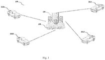
- the ADAS 100 includes a plurality of vehicles 102A-102C (hereinafter referred to as 102), all connected to a server 104.
- the plurality of vehicles 102 are connected to the server 104 through wireless communication protocols.
- Wireless communication protocols can be one among a mobile communication protocol, or satellite communication protocol.
- Each vehicle from the plurality of vehicles 102 includes an advanced driver assistance device 200 (to be described in detail in FIG. 2 ).
- the plurality of vehicles can be one among cars, trucks, buses, etc.
- the server 104 is a cloud computing server placed remotely from the plurality of vehicles 102 connected to it.
- the server 104 further includes a database 106 that stores historical combination situations, that included critical information, and reaction of drivers of the plurality of vehicles 102, when a feedback of certain intensity was provided to the drivers.
- the server 104 is able to identify or determine an ideal feedback that is a feedback from historical combination situations that had least number of negative reactions from the drivers in comparison to positive or neutral reactions for the same feedback. The ideal feedback is then transmitted back to the vehicle facing the current critical situation.
- the system 100 stores all the information in order to provide similar inputs to drivers in future critical conditions.
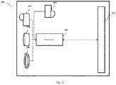
- FIG.2 illustrates a block diagram illustrating an advanced driver assistance device 200.
- the system 200 is vehicle mounted. In an embodiment of the invention, the system 200 is windshield mounted or mounted on "A" pillar of the vehicle. Furthermore, in another embodiment of the invention the system 200 can be a single casing device that will be explained in detail in conjunction with FIG. 3a and 3b .
- the system 200 includes a forward looking first camera 202.
- the forward-looking first camera 202 in an embodiment of the invention, can be a twin lens stereo camera.
- the first camera 202 is adapted to identify activity and objects that are within the close-range vicinity of the vehicle on which it is mounted.
- System 200 further includes, a forward-looking second camera 204.
- the second camera 204 is a long range narrow field camera that identifies activity and objects in long-range vicinity of the vehicle on which system 200 has been mounted.
- the system 200 includes a ranging module 206.
- the ranging module 206 identifies and determines distance of objects lying in front of the vehicle.
- the ranging module 206 in an embodiment of the invention, is a Light Detection and Ranging (LIDAR) module based on LIDAR method.
- LIDAR is a device distance to a target by illuminating that target with a laser light.
- LIDAR includes a transmitter to transmit laser light and a receiver to receive the reflected laser light.
- the system 200 includes a rear-looking third camera 208.
- the third camera 208 helps in identifying driver profile and monitor driver's state.
- Third camera 208 can identify the driver whether it's an old person, a woman, a young boy, etc. Also, the camera 208 has ability to identify various kinds of reactions of the driver. Whether the driver is happy, angry, sad, worried, tensed etc.
- the camera 208 is also equipped with features to identify whether driver is attentive or not, is the driver sleepy, or looking at phone etc. Hence, the third camera 208 is equipped to monitor driver state.
- System 200 further includes a processor 210, to which are connected the first camera 202, the second camera 204, the ranging module 206 and the third camera 208.
- Processor 210 takes inputs from all the three cameras and processes the information thus gathered.
- the information gathered from first camera 202, the second camera 204 and the ranging module 206 provides external environment information of the vehicle on which the system 200 is mounted.
- the processor 210 also takes input from the third camera 208 that gives the processor 210 information about the driver state and driver's profile.
- the processor 210 categorizes information into external and driver state information.
- the processor 210 after analyzing current external environment input and current driver state, identifies a threat or a critical situation that is upcoming based on the combination of current information or even based on individual information. Hence, the processor 210 queries the memory 112 to find such a combination and the corresponding feedback given to the driver and the driver reaction after the feedback was provided to the driver. Hence, based on the feedback given and the driver reaction to the historical combination of information, a decision is taken by the processor 210. The decision of the processor 210, decides whether to keep the intensity of the feedback same as previous, decrease, or increase the intensity of the feedback and forward the decision to a feedback module 212 of the vehicle. Feedback module can either give a visual warning to the driver, a haptic warning or an audio warning to the driver.
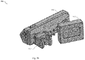
- FIG. 3a a line diagram illustrating front view of an advanced driver assistance system (ADAS) 300, in accordance with an embodiment of the invention.
- the ADAS 300 includes a single housing unit 302.
- the single housing unit 302 is made up of anyone or a combination of a plastic, a fiber, a metal, etc.
- Single housing unit 302 houses a plurality of camera modules.
- the camera modules include a first camera 304 that is, in an embodiment, a stereo camera and hence is a twin lens camera adapted to capture activity and identify objects in close-range vicinity of the vehicle.
- the first camera 304 is adapted to function efficiently in low speed ranges of the vehicle that is in a range of 1-20 mph.
- the ADAS 300 includes a second camera 306.
- the second camera 306 can be a long-range, narrow field camera adapted to identify activity and objects in long-range vicinity of the vehicle.
- the second camera 306 functions efficiently at higher speed that is in speed more than 20 mph.
- the ADAS 300 further includes a ranging module 308.
- the ranging module 308 is a Light and Detection Ranging (LIDAR) module.
- the ranging module 308 determines distance to the objects in front of the vehicle to which ADAS 300 is mounted.
- the ranging module includes a laser emitter and a laser receiver. The emitter, emits laser waves which when reflects from the object is received by the receiver and hence calculates the distance to that object. In this way, the ranging module keeps in check what all objects are in-front and what is a safe distance from such objects.
- the ADAS 300 may have a control unit 310 that may be placed on dashboard of the vehicle whereas ADAS 300 might be mounted on windshield of the vehicle. All data is although captured by ADAS 300 however, processing might take place within the control unit 310 that might also control feedback input to the driver.
- FIG. 3b a line diagram illustrating rear view of the ADAS 300.
- the ADAS 300 includes the single housing unit 302.
- the DSM device 312 is adapted to monitor driver state.
- the driver state may include driver profiling like driver age, driver sex, driving behavior.
- driver monitoring may include emotions like sad, happy, angry, drowsy, sleepy, tired, anxious etc.
- the warning device 302 can be either a display device for a visual warning, or can give an audiovisual warning, an audio warning alone or can be attached to the control unit 310 which in turn is connected to an electronic control unit (ECU) of the vehicle (not shown in figure) for a haptic warning provided to driver through the steering.
- ECU electronice control unit
- the DSM module 312 also captures reaction of the driver to feedback given in some situations and this information is stored in the memory 112.
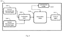
- the processor 210 is either placed within the ADAS 300 or can be placed in the control unit 310.
- the processor 210 includes an external environment data collection engine 2102. This external environment data collection engine takes inputs from the first camera 202, the second camera 204, the ranging module 206 and combines the information to form external environment data.
- the processor 210 also includes an internal environment data collection engine 2104, that is adapted to take input from the third camera 208 that identifies driver state.
- Processor 210 further includes a combination engine 2106 that takes its input from the external environment data collection engine 2102 and the internal environment data collection engine 2104 and combines this information to form a current situation combination.
- the current situation combination is then sent to an interpretation engine 2108.
- the interpretation engine 2108 determines whether it is a critical situation or not.
- Critical situation to a person ordinarily skilled in the art would appreciate, will be a situation that requires feedback to the driver like, speed limit in approaching road is 45 mph however, driver is drowsy. Such a situation is a critical situation.
- the interpretation engine 2108 identifies such situation from the current situation combination.
- the interpretation engine 2108 then initiates a communication module 2110 that connects with the server 104 to fetch an ideal feedback from the database 106 within the server 104.
- FIG. 5 a flow chart illustrating a method 500 for real-time driver assistance, in accordance to an embodiment of the invention.
- the method 500 analyzes current situation in and around the vehicle and the driver state and provides feedback to the driver by analyzing historically similar situation.
- the method 500 starts at step 502 at which current external environment data is gathered using the advanced driver assistance device (ADAD) 300.
- ADAD advanced driver assistance device
- the current external environment data is collected using the first camera 304, the second camera 306 and the ranging module 308.
- driver's current state is captured.
- a current combination situation is generated using the external environment and the driver current state.
- the interpretation engine 2108 of the processor 210 determines, whether or not there is a critical situation upcoming in the current situation combination. If no, the method is restarted at step 502. However, if there is a critical situation determined, then, at step 508, the processor 210 transmits the current situation combination to the server 104.
- the server 104 determines the ideal feedback for the current situation combination using historically similar situation combinations stored in the database 106 maintaining a common pool of various situation combinations and corresponding reaction of various drivers to different intensity feedbacks provided to them. Hence, for a similar kind of situation various intensity feedbacks and driver reactions to such various intensities are also stored within the database 106.
- the processor 210 receives the ideal feedback from the server 104 which at step 512 is provided or applied to the driver of the vehicle facing the critical situation.
- the ideal feedback is the feedback which has least number of negative driver reactions comparatively.
- FIG. 6 a flow chart illustrating a method 600 of determining ideal feedback to the current situation combination.
- the method starts at step 602, at which the server 104 receives the current situation combination information from the processor 210 after the processor 210 has identified that there is a critical situation that the vehicle from the plurality of vehicles 102 is facing.
- the server 104 after receiving the current situation combination from the processor 210, at step 604 fetches a similar historical situation combination from the database 106.
- the database 106 maintains a common pool of various situation combinations faced by drivers of the plurality of vehicles 102 and their corresponding reactions to various intensity feedbacks provided to drivers.
- the server 104 extracts the GPS coordinates from the current situation combination for locating area within which the driver is.
- the server 104 checks if such a historical situation combination exists or not. If not, then the server 104 either communicates back with the processor 210 and informs that no similar combination exists and processor 210 gives a predetermined feedback to the driver or the server 104 itself transmits the predetermined feedback to the processor 210 which is then provided to the driver at step 6062.
- the predetermined feedback can be either an auto-corrective action that is assistive breaking, wipers on etc. Also, in other embodiment of the invention, the predetermined feedback provided is based on current driver state information.
- the server 104 fetches corresponding feedbacks provided to the drivers at that time. Now, if at step 610, no such feedback is available within the database 106, then the method 600 is directed to step 6062 again. However, if such feedback is available within the database 106, then at step 612, the server fetches the corresponding driver reaction for the feedback provided. In an embodiment of the invention, the server 104 fetches corresponding feedback that was provided to the drivers at that particular location which is extracted by GPS coordinates.
- the server 104 checks if the reaction data is available or not. If the reaction data is not available, then the server 104 reverts to step 6062 for assistive correction or predetermined feedback. However, in case the reaction data is available, then the server 104 determines ideal feedback for the current situation combination. Ideal feedback is identified by gathering feedback of what intensity has been provided to the drivers facing similar kind of situations. Now, as depicted in FIG. 7 , a graph illustrating a comparative analysis for ideal feedback, for a similar situation, four degrees of intensities were provided i.e. SFI 1, SFI 2, SFI 3 and SFI 4. The three columns depict positive, negative and neutral reactions of the number of users for a complete set of data available within the database 106.
- the server 104 determines that for the current situation combination, the intensity of feedback is to be same as that in SFI 1, since comparatively the number of negative reactions to the intensity of the feedback SFI 1 is less as compared to a combination of positive or neutral, or individually positive, or individually neutral.
- the comparisons can be prioritized and weighted as well.
- Weightage of combination of positive with neutral is more than individually positive which is higher than individually neutral. Hence, comparatively the feedback intensity of SFI 1 is best suited for current situation combination.
- Driver emotions are defined as positive, negative and neutral. Positive driver emotion means there is a little complacency in the driver. This could be due to confidence of the driver or his driving style.
- Neutral driver emotion is described as no emotion from the driver, that means the driver is OK with the kind of feedback provided. Negative emotion is defined as frightened or scared or anxious due to the feedback provided.
- the ideal feedback is transmitted to the processor 210 as a feedback input.
- each block in the flowchart or block diagrams may represent a module, segment, or portion of instructions, which comprises one or more executable instructions for implementing the specified logical function(s).
- the functions noted in the block may occur out of the order noted in the figures.
- two blocks shown in succession may, in fact, be executed substantially concurrently, or the blocks may sometimes be executed in the reverse order, depending upon the functionality involved.
- each block of the block diagrams and/or flowchart illustration, and combinations of blocks in the block diagrams and/or flowchart illustration can be implemented by special purpose hardware-based systems that perform the specified functions or acts or carry out combinations of special purpose hardware and computer instructions.
Abstract
Description
- This invention relates to an advanced driver assistance system (ADAS) and more particularly to an ADAS utilizing artificial intelligence techniques on a common pool of driver reaction to various driver feedback provided to drivers of different connected vehicles at different situations.
- Driver assistance systems are being widely used these days in vehicles. These systems help a driver to be attentive to the road by providing various kinds of information to the driver of the vehicle. Typically, such systems are in-built to the vehicle and vary from vehicle to vehicle. There are various ways in which the driver assistance systems help driver of the vehicle. In one such way, the driver assistance systems are equipped with front looking cameras that identify approaching situations. Then, a corrective action is taken in such situation.
- Another type of driver assistance systems utilizes a driver state monitoring camera in addition to the forward-looking cameras. Data from both the modules is fused together and a warning is provided based on predictive danger due to a current situation. However, there is no measure of how the warning is provided and to what degree the warning should be applied.
- Therefore, there exists the need for a better driver assistance system.
- The present invention comprises a driver assistance device having one or more of the features recited in the appended claims and/or one or more of the following features, which alone or in any combination may comprise patentable subject matter:
- The objective of the invention is to provide an advanced driver assistance system (ADAS) with retrieval of ideal feedback to be provided in case of a current critical situation.
- Accordingly, in an embodiment of the invention, there is provided an advanced driver assistance system (ADAS), wherein the system comprises a plurality of vehicles, wherein each of the plurality of vehicles includes, a forward-looking first camera, that is adapted to identify activity and objects in short-range vicinity of the vehicle. The system further includes a forward looking second camera, adapted to identify activity and objects in long-range vicinity of the vehicle. The system also includes a ranging module, adapted to measure distance objects in a straight path in-front of the vehicle. The system, further includes, a rear-looking third camera, that monitors driver state. The system also includes a processor, configured to receive inputs from the first camera, the second camera, the ranging module, the third camera. Processor identifies an upcoming critical situation from the inputs and transmits the critical situation information. Furthermore, the system includes a server, to which each of the plurality of vehicles is connected, that is configured to receive the critical situation information, wherein the server further maintains a database of historical reactions of drivers, of each of the plurality of connected vehicles, to feedback to critical situations faced by drivers and, wherein the server is further configured to identify and transmit, to the processor, ideal feedback to be provided to the driver of the vehicle facing the critical situation in real-time.
- According to another aspect of the invention, there is provided a method for real-time driver assistance. The method includes gathering of external environment through a plurality of forward looking cameras connected to a processor; the method further includes capturing current driver state information through at least one rear looking camera, connected to the processor; generating, by the processor a combination of the current external environment and the current driver state information; determining, by the processor, a critical situation from the current combination information; transmitting, by the processor, the current combination information to a server through wireless communication protocol; and
receiving, by the processor, an ideal feedback to the current combination information based on common pool of historical combination information similar to the combination generated by the processor from the server, wherein the server is configured to store a plurality of historical combinations of external environment and corresponding driver state data and a corresponding driver reaction to a feedback offered to the driver for a particular combination of external environment and driver state during the particular combination; and providing, by the processor, the ideal feedback to the driver of the vehicle for the critical situation. - Additional features and advantages are realized through the techniques of the present disclosure. Other embodiments and aspects of the present disclosure are described in detail herein and are considered a part of the present disclosure. For a better understanding of the present disclosure with advantages and features, refer to the description and to the drawings.
- The foregoing summary, as well as the following detailed description of various embodiments, is better understood when read in conjunction with the drawings provided herein. For the purpose of illustration, there is shown in the drawings exemplary embodiments; however, the presently disclosed subject matter is not limited to the specific methods and instrumentalities disclosed.
-
FIG. 1 is a block diagram illustrating an advanced driver assistance system, in accordance with an embodiment of the invention. -
FIG. 2 is a line diagram illustrating an advanced driver assistance device for functioning of the driver assistance system, in accordance with an embodiment of the invention. -
FIG. 3a is a line diagram illustrating front view of an advanced driver assistance device, in accordance with an embodiment of the invention. -
FIG. 3b is a line diagram illustrating rear view of an advanced driver assistance device, in accordance with an embodiment of the invention. -
FIG. 4 is a block diagram illustrating a processor module, in accordance to an embodiment of the invention. -
FIG. 5 is a flow chart illustrating a method of real-time driver assistance, in accordance to an embodiment of the invention. -
FIG. 6 is a flow chart illustrating a method of determining ideal feedback, in accordance to an embodiment of the invention. -
FIG. 7 is a graph illustrating a comparative study for various driver reactions, in accordance to an embodiment of the invention. - The following detailed description is directed to certain specific embodiments of the invention. However, the invention can be embodied in a multitude of different ways as defined and covered by the claims and their equivalents. In this description, reference is made to the drawings wherein like parts are designated with like numerals throughout.
- Unless otherwise noted in this specification or in the claims, all of the terms used in the specification and the claims will have the meanings normally ascribed to these terms by workers in the art.
- Hereinafter, preferred embodiments of the invention will be described in detail in reference to the accompanying drawings. It should be understood that like reference numbers are used to indicate like elements even in different drawings. Detailed descriptions of known functions and configurations that may unnecessarily obscure the aspect of the invention have been omitted.
- The presently disclosed subject matter is described with specificity to meet statutory requirements. However, the description itself is not intended to limit the scope of this patent. Rather, the inventors have contemplated that the claimed subject matter might also be embodied in other ways, to include different steps or elements similar to the ones described in this document, in conjunction with other present or future technologies. Moreover, although the term "step" may be used herein to connote different aspects of methods employed, the term should not be interpreted as implying any particular order among or between various steps herein disclosed unless and except when the order of individual steps is explicitly described.
- Referring now to
FIG. 1 , illustrating a line diagram of an advanced driver assistance system (ADAS) 100. The ADAS 100 includes a plurality of vehicles 102A-102C (hereinafter referred to as 102), all connected to aserver 104. In an embodiment of the invention, the plurality of vehicles 102 are connected to theserver 104 through wireless communication protocols. Wireless communication protocols can be one among a mobile communication protocol, or satellite communication protocol. Each vehicle from the plurality of vehicles 102 includes an advanced driver assistance device 200 (to be described in detail inFIG. 2 ). In an embodiment of the invention, the plurality of vehicles can be one among cars, trucks, buses, etc. Also, in another embodiment of the invention, theserver 104 is a cloud computing server placed remotely from the plurality of vehicles 102 connected to it. Theserver 104, further includes adatabase 106 that stores historical combination situations, that included critical information, and reaction of drivers of the plurality of vehicles 102, when a feedback of certain intensity was provided to the drivers. Theserver 104 is able to identify or determine an ideal feedback that is a feedback from historical combination situations that had least number of negative reactions from the drivers in comparison to positive or neutral reactions for the same feedback. The ideal feedback is then transmitted back to the vehicle facing the current critical situation. Further, thesystem 100 stores all the information in order to provide similar inputs to drivers in future critical conditions. Referring now toFIG.2 , illustrates a block diagram illustrating an advanceddriver assistance device 200. Thesystem 200 is vehicle mounted. In an embodiment of the invention, thesystem 200 is windshield mounted or mounted on "A" pillar of the vehicle. Furthermore, in another embodiment of the invention thesystem 200 can be a single casing device that will be explained in detail in conjunction withFIG. 3a and3b . Thesystem 200 includes a forward lookingfirst camera 202. The forward-lookingfirst camera 202, in an embodiment of the invention, can be a twin lens stereo camera. Thefirst camera 202 is adapted to identify activity and objects that are within the close-range vicinity of the vehicle on which it is mounted. -
System 200 further includes, a forward-looking second camera 204. The second camera 204 is a long range narrow field camera that identifies activity and objects in long-range vicinity of the vehicle on whichsystem 200 has been mounted. Furthermore, thesystem 200, includes a rangingmodule 206. The rangingmodule 206 identifies and determines distance of objects lying in front of the vehicle. The rangingmodule 206, in an embodiment of the invention, is a Light Detection and Ranging (LIDAR) module based on LIDAR method. As already known in the art, LIDAR is a device distance to a target by illuminating that target with a laser light. For this purpose, LIDAR includes a transmitter to transmit laser light and a receiver to receive the reflected laser light. - Still referring to
FIG. 2 , thesystem 200 includes a rear-lookingthird camera 208. Thethird camera 208 helps in identifying driver profile and monitor driver's state.Third camera 208 can identify the driver whether it's an old person, a woman, a young boy, etc. Also, thecamera 208 has ability to identify various kinds of reactions of the driver. Whether the driver is happy, angry, sad, worried, tensed etc. Thecamera 208 is also equipped with features to identify whether driver is attentive or not, is the driver sleepy, or looking at phone etc. Hence, thethird camera 208 is equipped to monitor driver state. -
System 200, further includes aprocessor 210, to which are connected thefirst camera 202, the second camera 204, the rangingmodule 206 and thethird camera 208.Processor 210, takes inputs from all the three cameras and processes the information thus gathered. The information gathered fromfirst camera 202, the second camera 204 and the rangingmodule 206 provides external environment information of the vehicle on which thesystem 200 is mounted. Theprocessor 210, also takes input from thethird camera 208 that gives theprocessor 210 information about the driver state and driver's profile. Theprocessor 210 categorizes information into external and driver state information. - Still referring to
FIG. 1 , theprocessor 210, after analyzing current external environment input and current driver state, identifies a threat or a critical situation that is upcoming based on the combination of current information or even based on individual information. Hence, theprocessor 210 queries the memory 112 to find such a combination and the corresponding feedback given to the driver and the driver reaction after the feedback was provided to the driver. Hence, based on the feedback given and the driver reaction to the historical combination of information, a decision is taken by theprocessor 210. The decision of theprocessor 210, decides whether to keep the intensity of the feedback same as previous, decrease, or increase the intensity of the feedback and forward the decision to afeedback module 212 of the vehicle. Feedback module can either give a visual warning to the driver, a haptic warning or an audio warning to the driver. - Now referring to
FIG. 3a , a line diagram illustrating front view of an advanced driver assistance system (ADAS) 300, in accordance with an embodiment of the invention. TheADAS 300 includes asingle housing unit 302. In an embodiment of the invention, thesingle housing unit 302 is made up of anyone or a combination of a plastic, a fiber, a metal, etc.Single housing unit 302 houses a plurality of camera modules. The camera modules include afirst camera 304 that is, in an embodiment, a stereo camera and hence is a twin lens camera adapted to capture activity and identify objects in close-range vicinity of the vehicle. Thefirst camera 304 is adapted to function efficiently in low speed ranges of the vehicle that is in a range of 1-20 mph. Further, theADAS 300 includes asecond camera 306. Thesecond camera 306 can be a long-range, narrow field camera adapted to identify activity and objects in long-range vicinity of the vehicle. Thesecond camera 306 functions efficiently at higher speed that is in speed more than 20 mph. - Still referring to
FIG. 3a , theADAS 300 further includes a rangingmodule 308. The rangingmodule 308 is a Light and Detection Ranging (LIDAR) module. The rangingmodule 308 determines distance to the objects in front of the vehicle to whichADAS 300 is mounted. For this, the ranging module includes a laser emitter and a laser receiver. The emitter, emits laser waves which when reflects from the object is received by the receiver and hence calculates the distance to that object. In this way, the ranging module keeps in check what all objects are in-front and what is a safe distance from such objects. TheADAS 300 may have acontrol unit 310 that may be placed on dashboard of the vehicle whereasADAS 300 might be mounted on windshield of the vehicle. All data is although captured byADAS 300 however, processing might take place within thecontrol unit 310 that might also control feedback input to the driver. - Now referring to
FIG. 3b , a line diagram illustrating rear view of theADAS 300. As indicated above, theADAS 300 includes thesingle housing unit 302. At the rear side of theADAS 300 is attached a driver state monitoring (DSM)device 312. TheDSM device 312 is adapted to monitor driver state. The driver state may include driver profiling like driver age, driver sex, driving behavior. Also, driver monitoring may include emotions like sad, happy, angry, drowsy, sleepy, tired, anxious etc. There is also attached awarning device 302 on rear-side of theADAS 300. Thewarning device 302 can be either a display device for a visual warning, or can give an audiovisual warning, an audio warning alone or can be attached to thecontrol unit 310 which in turn is connected to an electronic control unit (ECU) of the vehicle (not shown in figure) for a haptic warning provided to driver through the steering. TheDSM module 312 also captures reaction of the driver to feedback given in some situations and this information is stored in the memory 112. - Now referring to
FIG. 4 illustrating internals of theprocessor 210, in accordance with an embodiment of the invention. Theprocessor 210 is either placed within theADAS 300 or can be placed in thecontrol unit 310. Theprocessor 210 includes an external environmentdata collection engine 2102. This external environment data collection engine takes inputs from thefirst camera 202, the second camera 204, the rangingmodule 206 and combines the information to form external environment data. Theprocessor 210 also includes an internal environment data collection engine 2104, that is adapted to take input from thethird camera 208 that identifies driver state.Processor 210 further includes a combination engine 2106 that takes its input from the external environmentdata collection engine 2102 and the internal environment data collection engine 2104 and combines this information to form a current situation combination. - The current situation combination is then sent to an
interpretation engine 2108. Theinterpretation engine 2108 then determines whether it is a critical situation or not. Critical situation, to a person ordinarily skilled in the art would appreciate, will be a situation that requires feedback to the driver like, speed limit in approaching road is 45 mph however, driver is drowsy. Such a situation is a critical situation. Hence, theinterpretation engine 2108 identifies such situation from the current situation combination. After fetching the critical situation from the current situation combination, theinterpretation engine 2108 then initiates acommunication module 2110 that connects with theserver 104 to fetch an ideal feedback from thedatabase 106 within theserver 104. - Now referring to
FIG. 5 , a flow chart illustrating amethod 500 for real-time driver assistance, in accordance to an embodiment of the invention. Themethod 500 analyzes current situation in and around the vehicle and the driver state and provides feedback to the driver by analyzing historically similar situation. Themethod 500 starts atstep 502 at which current external environment data is gathered using the advanced driver assistance device (ADAD) 300. The current external environment data, as already explained above, is collected using thefirst camera 304, thesecond camera 306 and the rangingmodule 308. Further, atstep 504, driver's current state is captured. Now moving atstep 506, a current combination situation is generated using the external environment and the driver current state. Atstep 507, theinterpretation engine 2108 of theprocessor 210, determines, whether or not there is a critical situation upcoming in the current situation combination. If no, the method is restarted atstep 502. However, if there is a critical situation determined, then, atstep 508, theprocessor 210 transmits the current situation combination to theserver 104. Theserver 104 determines the ideal feedback for the current situation combination using historically similar situation combinations stored in thedatabase 106 maintaining a common pool of various situation combinations and corresponding reaction of various drivers to different intensity feedbacks provided to them. Hence, for a similar kind of situation various intensity feedbacks and driver reactions to such various intensities are also stored within thedatabase 106. Further, atstep 510, theprocessor 210 receives the ideal feedback from theserver 104 which atstep 512 is provided or applied to the driver of the vehicle facing the critical situation. In an embodiment of the invention, the ideal feedback is the feedback which has least number of negative driver reactions comparatively. - Now referring to
FIG. 6 , a flow chart illustrating a method 600 of determining ideal feedback to the current situation combination. The method starts at step 602, at which theserver 104 receives the current situation combination information from theprocessor 210 after theprocessor 210 has identified that there is a critical situation that the vehicle from the plurality of vehicles 102 is facing. Theserver 104 after receiving the current situation combination from theprocessor 210, at step 604 fetches a similar historical situation combination from thedatabase 106. As disclosed earlier, thedatabase 106 maintains a common pool of various situation combinations faced by drivers of the plurality of vehicles 102 and their corresponding reactions to various intensity feedbacks provided to drivers. In an embodiment of the invention, theserver 104 extracts the GPS coordinates from the current situation combination for locating area within which the driver is. - At step 606, the
server 104 checks if such a historical situation combination exists or not. If not, then theserver 104 either communicates back with theprocessor 210 and informs that no similar combination exists andprocessor 210 gives a predetermined feedback to the driver or theserver 104 itself transmits the predetermined feedback to theprocessor 210 which is then provided to the driver at step 6062. The predetermined feedback can be either an auto-corrective action that is assistive breaking, wipers on etc. Also, in other embodiment of the invention, the predetermined feedback provided is based on current driver state information. - Further, at step 608, if the historical situation combination is present, the
server 104 then fetches corresponding feedbacks provided to the drivers at that time. Now, if atstep 610, no such feedback is available within thedatabase 106, then the method 600 is directed to step 6062 again. However, if such feedback is available within thedatabase 106, then at step 612, the server fetches the corresponding driver reaction for the feedback provided. In an embodiment of the invention, theserver 104 fetches corresponding feedback that was provided to the drivers at that particular location which is extracted by GPS coordinates. - At step 614, the
server 104, checks if the reaction data is available or not. If the reaction data is not available, then theserver 104 reverts to step 6062 for assistive correction or predetermined feedback. However, in case the reaction data is available, then theserver 104 determines ideal feedback for the current situation combination. Ideal feedback is identified by gathering feedback of what intensity has been provided to the drivers facing similar kind of situations. Now, as depicted inFIG. 7 , a graph illustrating a comparative analysis for ideal feedback, for a similar situation, four degrees of intensities were provided i.e.SFI 1, SFI 2, SFI 3 and SFI 4. The three columns depict positive, negative and neutral reactions of the number of users for a complete set of data available within thedatabase 106. Hence, theserver 104 determines that for the current situation combination, the intensity of feedback is to be same as that inSFI 1, since comparatively the number of negative reactions to the intensity of thefeedback SFI 1 is less as compared to a combination of positive or neutral, or individually positive, or individually neutral. - In other embodiment of the invention, the comparisons can be prioritized and weighted as well.
- Weightage of combination of positive with neutral is more than individually positive which is higher than individually neutral. Hence, comparatively the feedback intensity of
SFI 1 is best suited for current situation combination. - Driver emotions are defined as positive, negative and neutral. Positive driver emotion means there is a little complacency in the driver. This could be due to confidence of the driver or his driving style. Neutral driver emotion is described as no emotion from the driver, that means the driver is OK with the kind of feedback provided. Negative emotion is defined as frightened or scared or anxious due to the feedback provided.
- At step 618, the ideal feedback is transmitted to the
processor 210 as a feedback input. - Aspects of the present subject matter are described herein with reference to flowchart illustrations and/or block diagrams of methods and apparatus (systems) according to embodiments of the subject matter. It will be understood that each block of the flowchart illustrations and/or block diagrams, and combinations of blocks in the flowchart illustrations and/or block diagrams, can be implemented by computer readable program instructions.
- While there has been shown, and described herein what are presently considered the preferred embodiments of the present disclosure, it will be apparent to those skilled in the art that various changes and modifications can be made therein without departing from the scope of the present disclosure as defined by the appended claims.
- The flowchart and block diagrams in the Figures illustrate the architecture, functionality, and operation of possible implementations of systems, methods, and computer program products according to various embodiments of the present subject matter. In this regard, each block in the flowchart or block diagrams may represent a module, segment, or portion of instructions, which comprises one or more executable instructions for implementing the specified logical function(s).
- In some alternative implementations, the functions noted in the block may occur out of the order noted in the figures. For example, two blocks shown in succession may, in fact, be executed substantially concurrently, or the blocks may sometimes be executed in the reverse order, depending upon the functionality involved. It will also be noted that each block of the block diagrams and/or flowchart illustration, and combinations of blocks in the block diagrams and/or flowchart illustration, can be implemented by special purpose hardware-based systems that perform the specified functions or acts or carry out combinations of special purpose hardware and computer instructions.
- While certain embodiments have been described, these embodiments have been presented by way of example only, and are not intended to limit the scope of the present disclosure. Indeed, the novel methods, devices, and systems described herein may be embodied in a variety of other forms. Furthermore, various omissions, substitutions, and changes in the form of the methods, devices, and systems described herein may be made without departing from the spirit of the present disclosure. The accompanying claims and their equivalents are intended to cover such forms or modifications as would fall within the scope and spirit of the present disclosure.
Claims (15)
- An advanced driver assistance system, wherein the system comprises;
a plurality of vehicles, wherein to each of the plurality of vehicles includes:a forward looking first camera, adapted to identify activity and objects in short-range vicinity of the vehicle;a forward looking second camera, adapted to identify activity and objects in long-range vicinity of the vehicle;a ranging module, adapted to measure distance to objects in a straight path;a rear looking third camera, wherein the third camera is configured to monitor driver state;a processor, configured to receive inputs from the forward looking first camera, the forward looking second camera, and the ranging module, wherein the processor identifies a critical situation based on the inputs and transmit the critical situation information;a server, to which each of the plurality of vehicles is connected, configured to receive the critical situation information, wherein the server further maintains a database of historical reactions of drivers, of each of the plurality of connected vehicles, to feedback to critical situations faced by drivers and, wherein the server is further configured to identify and transmit, to the processor, ideal feedback to be provided to the driver of the vehicle facing the critical situation in real-time. - The system of claim 1, wherein the first camera is a stereo camera having a short focal length.
- The system of claim 1, wherein the second camera is a long range narrow field camera having a long focal length.
- The system of claim 1, wherein the ranging module is a is a light detection and ranging (LiDAR) unit.
- The system of claim 1, wherein the third camera monitors driver state by capturing eye gaze and facial expressions of the driver.
- The system of claim 1, wherein the historical reactions includes anyone or a combination of intensity of reaction, time to braking, or facial expressions during reaction.
- The system of claim 1, wherein the feedback is any one or a combination of an audio feedback, a visual feedback, or a haptic feedback.
- The system of claim 1, wherein the ideal feedback is feedback that has comparatively least number of negative driver reactions.
- A real-time driver assistance method, comprising;
gathering current external environment information through a plurality of forward looking cameras connected to a processor;
capturing current driver state information through at least one rear looking camera, connected to the processor;
generating, by the processor a current combination information based on the current external environment and the current driver state information;
determining, by the processor, a critical situation from the current combination information;
transmitting, by the processor, the current combination information to a server through wireless communication protocol; and
receiving, by the processor, an ideal feedback to the current combination information based on common pool of historical combination information similar to the combination generated by the processor from the server, wherein the server is configured to store a plurality of historical combinations of external environment and corresponding driver state data and a corresponding driver reaction to a feedback offered to the driver for a particular combination of external environment and driver state during the particular combination; and
providing, by the processor, the ideal feedback to the driver of the vehicle for the critical situation. - The real-time driver assistance method of claim 9, wherein the plurality of forward looking cameras includes anyone or a combination of a stereo camera, or a long range narrow field camera.
- The real-time driver assistance method of claim 9, wherein the server is a remote server.
- The real-time driver assistance method of claim 9, wherein the reaction includes anyone or a combination of intensity of reaction, time to braking, or facial expressions during reaction.
- The real-time driver assistance method of claim 12, wherein profile of the driver is stored in the external environment captured using the at least one rear looking camera.
- The real-time driver assistance method of claim 13, wherein the driver profile includes data like age bracket, sex, or general emotional state while driving.
- The real-time driver assistance method of claim 9, wherein the processor also combines the driver profile along with the historical reaction to the similar historical combination.
Applications Claiming Priority (1)
| Application Number | Priority Date | Filing Date | Title |
|---|---|---|---|
| IN201711008493 | 2017-03-10 |
Publications (2)
| Publication Number | Publication Date |
|---|---|
| EP3373193A1 true EP3373193A1 (en) | 2018-09-12 |
| EP3373193B1 EP3373193B1 (en) | 2023-09-20 |
Family
ID=59061759
Family Applications (1)
| Application Number | Title | Priority Date | Filing Date |
|---|---|---|---|
| EP17169412.8A Active EP3373193B1 (en) | 2017-03-10 | 2017-05-04 | Method and system for artificial intelligence based advanced driver assistance |
Country Status (2)
| Country | Link |
|---|---|
| US (1) | US10843625B2 (en) |
| EP (1) | EP3373193B1 (en) |
Cited By (1)
| Publication number | Priority date | Publication date | Assignee | Title |
|---|---|---|---|---|
| CN111634233A (en) * | 2020-05-25 | 2020-09-08 | 杭州鸿泉物联网技术股份有限公司 | Safe driving system and method |
Families Citing this family (5)
| Publication number | Priority date | Publication date | Assignee | Title |
|---|---|---|---|---|
| US10894542B2 (en) * | 2018-10-30 | 2021-01-19 | International Business Machines Corporation | Driving feedback based safety system |
| US11110940B2 (en) | 2019-12-06 | 2021-09-07 | Wipro Limited | Method and system for generating touch-based alerts to a driver in a vehicle |
| WO2021133832A1 (en) * | 2019-12-27 | 2021-07-01 | Waymo Llc | Conditional behavior prediction for autonomous vehicles |
| DE102020111878A1 (en) | 2020-04-30 | 2021-11-04 | Bayerische Motoren Werke Aktiengesellschaft | PROCEDURE FOR ISSUING DRIVING INSTRUCTIONS AND A MOTOR VEHICLE |
| CN113022575B (en) * | 2021-03-29 | 2023-09-12 | 英博超算(南京)科技有限公司 | Vehicle-mounted forward-looking ADAS integrated machine system and method with DVR and AI |
Citations (2)
| Publication number | Priority date | Publication date | Assignee | Title |
|---|---|---|---|---|
| US20160050356A1 (en) * | 2014-08-18 | 2016-02-18 | Trimble Navigation Limited | System and method for modifying onboard event detection and/or image capture strategy using external source data |
| JP2017019308A (en) * | 2015-07-07 | 2017-01-26 | 本田技研工業株式会社 | Vehicle control device, vehicle control method, and vehicle control program |
Family Cites Families (3)
| Publication number | Priority date | Publication date | Assignee | Title |
|---|---|---|---|---|
| GB2529997B (en) * | 2014-05-01 | 2019-01-02 | Jaguar Land Rover Ltd | Vehicle communication system with occupant monitoring |
| US9476729B2 (en) * | 2014-05-29 | 2016-10-25 | GM Global Technology Operations LLC | Adaptive navigation and location-based services based on user behavior patterns |
| EP3761226A1 (en) * | 2015-02-10 | 2021-01-06 | Mobileye Vision Technologies Ltd. | Sparse map for autonomous vehicle navigation |
-
2017
- 2017-05-04 EP EP17169412.8A patent/EP3373193B1/en active Active
- 2017-05-11 US US15/592,587 patent/US10843625B2/en active Active
Patent Citations (2)
| Publication number | Priority date | Publication date | Assignee | Title |
|---|---|---|---|---|
| US20160050356A1 (en) * | 2014-08-18 | 2016-02-18 | Trimble Navigation Limited | System and method for modifying onboard event detection and/or image capture strategy using external source data |
| JP2017019308A (en) * | 2015-07-07 | 2017-01-26 | 本田技研工業株式会社 | Vehicle control device, vehicle control method, and vehicle control program |
Cited By (1)
| Publication number | Priority date | Publication date | Assignee | Title |
|---|---|---|---|---|
| CN111634233A (en) * | 2020-05-25 | 2020-09-08 | 杭州鸿泉物联网技术股份有限公司 | Safe driving system and method |
Also Published As
| Publication number | Publication date |
|---|---|
| EP3373193B1 (en) | 2023-09-20 |
| US20180257564A1 (en) | 2018-09-13 |
| US10843625B2 (en) | 2020-11-24 |
Similar Documents
| Publication | Publication Date | Title |
|---|---|---|
| US10843625B2 (en) | Method and system for artificial intelligence based advanced driver assistance | |
| US10926699B2 (en) | Method and system for historical state based advanced driver assistance | |
| US10525879B2 (en) | Method and system for vehicle status based advanced driver assistance | |
| CN107856671B (en) | Method and system for road condition identification through automobile data recorder | |
| US11577734B2 (en) | System and method for analysis of driver behavior | |
| CN111260482B (en) | Information processing terminal, computer-readable storage medium, and control method | |
| US11144052B2 (en) | Readiness and identification by gaze and/or gesture pattern detection | |
| CN111055840A (en) | Vehicle-to-infrastructure (V2I) messaging system | |
| US20140354684A1 (en) | Symbology system and augmented reality heads up display (hud) for communicating safety information | |
| US10604160B2 (en) | Driver condition detection system | |
| CN113492849A (en) | Driving support device and data collection system | |
| CN112991684A (en) | Driving early warning method and device | |
| JP6891926B2 (en) | Vehicle systems, methods performed on vehicle systems, and driver assistance systems | |
| US11858414B2 (en) | Attention calling device, attention calling method, and computer-readable medium | |
| WO2018163490A1 (en) | Visual recognition support device, method, and program | |
| KR20200082456A (en) | Method and apparatus for managing health care information in vehicle | |
| US11643012B2 (en) | Driving assistance device, driving situation information acquisition system, driving assistance method, and program | |
| JP7014680B2 (en) | Gaze object detection device, gaze object detection method, and program | |
| JP7294483B2 (en) | Driving support device, driving support method and program | |
| US20230141584A1 (en) | Apparatus for displaying at least one virtual lane line based on environmental condition and method of controlling same | |
| US20230137349A1 (en) | System for data communication using vehicle camera, method therefor and vehicle for the same | |
| KR102175793B1 (en) | Method and apparatus for outputting an alarm for congitive impairment of driver | |
| KR20230136830A (en) | Driver assistance system and driver assistance method | |
| JP2018195184A (en) | Vehicle device, safe driving support system, safe driving support method | |
| CN116442907A (en) | Road condition display method and device based on pupil position of driver, vehicle and medium |
Legal Events
| Date | Code | Title | Description |
|---|---|---|---|
| PUAI | Public reference made under article 153(3) epc to a published international application that has entered the european phase |
Free format text: ORIGINAL CODE: 0009012 |
|
| STAA | Information on the status of an ep patent application or granted ep patent |
Free format text: STATUS: THE APPLICATION HAS BEEN PUBLISHED |
|
| AK | Designated contracting states |
Kind code of ref document: A1 Designated state(s): AL AT BE BG CH CY CZ DE DK EE ES FI FR GB GR HR HU IE IS IT LI LT LU LV MC MK MT NL NO PL PT RO RS SE SI SK SM TR |
|
| AX | Request for extension of the european patent |
Extension state: BA ME |
|
| STAA | Information on the status of an ep patent application or granted ep patent |
Free format text: STATUS: REQUEST FOR EXAMINATION WAS MADE |
|
| 17P | Request for examination filed |
Effective date: 20190312 |
|
| RBV | Designated contracting states (corrected) |
Designated state(s): AL AT BE BG CH CY CZ DE DK EE ES FI FR GB GR HR HU IE IS IT LI LT LU LV MC MK MT NL NO PL PT RO RS SE SI SK SM TR |
|
| STAA | Information on the status of an ep patent application or granted ep patent |
Free format text: STATUS: EXAMINATION IS IN PROGRESS |
|
| 17Q | First examination report despatched |
Effective date: 20190628 |
|
| STAA | Information on the status of an ep patent application or granted ep patent |
Free format text: STATUS: EXAMINATION IS IN PROGRESS |
|
| STAA | Information on the status of an ep patent application or granted ep patent |
Free format text: STATUS: EXAMINATION IS IN PROGRESS |
|
| REG | Reference to a national code |
Ref country code: DE Ref legal event code: R079 Ref document number: 602017074355 Country of ref document: DE Free format text: PREVIOUS MAIN CLASS: G06K0009000000 Ipc: G06V0020540000 Ref country code: DE Ref legal event code: R079 Free format text: PREVIOUS MAIN CLASS: G06K0009000000 Ipc: G06V0020540000 |
|
| GRAP | Despatch of communication of intention to grant a patent |
Free format text: ORIGINAL CODE: EPIDOSNIGR1 |
|
| STAA | Information on the status of an ep patent application or granted ep patent |
Free format text: STATUS: GRANT OF PATENT IS INTENDED |
|
| RIC1 | Information provided on ipc code assigned before grant |
Ipc: G08G 1/16 20060101ALI20230313BHEP Ipc: G08G 1/01 20060101ALI20230313BHEP Ipc: G07C 5/00 20060101ALI20230313BHEP Ipc: B60W 50/14 20120101ALI20230313BHEP Ipc: B60W 50/00 20060101ALI20230313BHEP Ipc: B60W 40/08 20120101ALI20230313BHEP Ipc: G06V 20/59 20220101ALI20230313BHEP Ipc: G06V 20/56 20220101ALI20230313BHEP Ipc: G06V 20/54 20220101AFI20230313BHEP |
|
| INTG | Intention to grant announced |
Effective date: 20230412 |
|
| GRAS | Grant fee paid |
Free format text: ORIGINAL CODE: EPIDOSNIGR3 |
|
| GRAA | (expected) grant |
Free format text: ORIGINAL CODE: 0009210 |
|
| STAA | Information on the status of an ep patent application or granted ep patent |
Free format text: STATUS: THE PATENT HAS BEEN GRANTED |
|
| AK | Designated contracting states |
Kind code of ref document: B1 Designated state(s): AL AT BE BG CH CY CZ DE DK EE ES FI FR GB GR HR HU IE IS IT LI LT LU LV MC MK MT NL NO PL PT RO RS SE SI SK SM TR |
|
| REG | Reference to a national code |
Ref country code: GB Ref legal event code: FG4D |
|
| REG | Reference to a national code |
Ref country code: CH Ref legal event code: EP |
|
| REG | Reference to a national code |
Ref country code: IE Ref legal event code: FG4D |
|
| REG | Reference to a national code |
Ref country code: DE Ref legal event code: R096 Ref document number: 602017074355 Country of ref document: DE |
|
| RAP2 | Party data changed (patent owner data changed or rights of a patent transferred) |
Owner name: NOVUS HI-TECH ROBOTIC SYSTEMZ PRIVATE LTD. |
|
| REG | Reference to a national code |
Ref country code: DE Ref legal event code: R081 Ref document number: 602017074355 Country of ref document: DE Owner name: NOVUS HI-TECH ROBOTIC SYSTEMZ PRIVATE LTD., GU, IN Free format text: FORMER OWNER: THE HI-TECH ROBOTIC SYSTEMZ LTD, GURUGRAM, HARYANA, IN |
|
| REG | Reference to a national code |
Ref country code: LT Ref legal event code: MG9D |
|
| PG25 | Lapsed in a contracting state [announced via postgrant information from national office to epo] |
Ref country code: GR Free format text: LAPSE BECAUSE OF FAILURE TO SUBMIT A TRANSLATION OF THE DESCRIPTION OR TO PAY THE FEE WITHIN THE PRESCRIBED TIME-LIMIT Effective date: 20231221 |
|
| REG | Reference to a national code |
Ref country code: NL Ref legal event code: MP Effective date: 20230920 |
|
| PG25 | Lapsed in a contracting state [announced via postgrant information from national office to epo] |
Ref country code: SE Free format text: LAPSE BECAUSE OF FAILURE TO SUBMIT A TRANSLATION OF THE DESCRIPTION OR TO PAY THE FEE WITHIN THE PRESCRIBED TIME-LIMIT Effective date: 20230920 Ref country code: RS Free format text: LAPSE BECAUSE OF FAILURE TO SUBMIT A TRANSLATION OF THE DESCRIPTION OR TO PAY THE FEE WITHIN THE PRESCRIBED TIME-LIMIT Effective date: 20230920 Ref country code: NO Free format text: LAPSE BECAUSE OF FAILURE TO SUBMIT A TRANSLATION OF THE DESCRIPTION OR TO PAY THE FEE WITHIN THE PRESCRIBED TIME-LIMIT Effective date: 20231220 Ref country code: LV Free format text: LAPSE BECAUSE OF FAILURE TO SUBMIT A TRANSLATION OF THE DESCRIPTION OR TO PAY THE FEE WITHIN THE PRESCRIBED TIME-LIMIT Effective date: 20230920 Ref country code: LT Free format text: LAPSE BECAUSE OF FAILURE TO SUBMIT A TRANSLATION OF THE DESCRIPTION OR TO PAY THE FEE WITHIN THE PRESCRIBED TIME-LIMIT Effective date: 20230920 Ref country code: HR Free format text: LAPSE BECAUSE OF FAILURE TO SUBMIT A TRANSLATION OF THE DESCRIPTION OR TO PAY THE FEE WITHIN THE PRESCRIBED TIME-LIMIT Effective date: 20230920 Ref country code: GR Free format text: LAPSE BECAUSE OF FAILURE TO SUBMIT A TRANSLATION OF THE DESCRIPTION OR TO PAY THE FEE WITHIN THE PRESCRIBED TIME-LIMIT Effective date: 20231221 Ref country code: FI Free format text: LAPSE BECAUSE OF FAILURE TO SUBMIT A TRANSLATION OF THE DESCRIPTION OR TO PAY THE FEE WITHIN THE PRESCRIBED TIME-LIMIT Effective date: 20230920 |
|
| REG | Reference to a national code |
Ref country code: AT Ref legal event code: MK05 Ref document number: 1614003 Country of ref document: AT Kind code of ref document: T Effective date: 20230920 |
|
| PG25 | Lapsed in a contracting state [announced via postgrant information from national office to epo] |
Ref country code: NL Free format text: LAPSE BECAUSE OF FAILURE TO SUBMIT A TRANSLATION OF THE DESCRIPTION OR TO PAY THE FEE WITHIN THE PRESCRIBED TIME-LIMIT Effective date: 20230920 |