EP3373188A1 - Security apparatus and operation method thereof - Google Patents
Security apparatus and operation method thereof Download PDFInfo
- Publication number
- EP3373188A1 EP3373188A1 EP16862443.5A EP16862443A EP3373188A1 EP 3373188 A1 EP3373188 A1 EP 3373188A1 EP 16862443 A EP16862443 A EP 16862443A EP 3373188 A1 EP3373188 A1 EP 3373188A1
- Authority
- EP
- European Patent Office
- Prior art keywords
- security
- security apparatus
- core circuit
- event information
- received
- Prior art date
- Legal status (The legal status is an assumption and is not a legal conclusion. Google has not performed a legal analysis and makes no representation as to the accuracy of the status listed.)
- Granted
Links
Images


Classifications
-
- G—PHYSICS
- G06—COMPUTING OR CALCULATING; COUNTING
- G06F—ELECTRIC DIGITAL DATA PROCESSING
- G06F21/00—Security arrangements for protecting computers, components thereof, programs or data against unauthorised activity
- G06F21/70—Protecting specific internal or peripheral components, in which the protection of a component leads to protection of the entire computer
- G06F21/71—Protecting specific internal or peripheral components, in which the protection of a component leads to protection of the entire computer to assure secure computing or processing of information
- G06F21/75—Protecting specific internal or peripheral components, in which the protection of a component leads to protection of the entire computer to assure secure computing or processing of information by inhibiting the analysis of circuitry or operation
- G06F21/755—Protecting specific internal or peripheral components, in which the protection of a component leads to protection of the entire computer to assure secure computing or processing of information by inhibiting the analysis of circuitry or operation with measures against power attack
-
- G—PHYSICS
- G06—COMPUTING OR CALCULATING; COUNTING
- G06F—ELECTRIC DIGITAL DATA PROCESSING
- G06F1/00—Details not covered by groups G06F3/00 - G06F13/00 and G06F21/00
- G06F1/26—Power supply means, e.g. regulation thereof
-
- G—PHYSICS
- G06—COMPUTING OR CALCULATING; COUNTING
- G06F—ELECTRIC DIGITAL DATA PROCESSING
- G06F21/00—Security arrangements for protecting computers, components thereof, programs or data against unauthorised activity
- G06F21/70—Protecting specific internal or peripheral components, in which the protection of a component leads to protection of the entire computer
- G06F21/71—Protecting specific internal or peripheral components, in which the protection of a component leads to protection of the entire computer to assure secure computing or processing of information
- G06F21/75—Protecting specific internal or peripheral components, in which the protection of a component leads to protection of the entire computer to assure secure computing or processing of information by inhibiting the analysis of circuitry or operation
-
- G—PHYSICS
- G06—COMPUTING OR CALCULATING; COUNTING
- G06F—ELECTRIC DIGITAL DATA PROCESSING
- G06F21/00—Security arrangements for protecting computers, components thereof, programs or data against unauthorised activity
- G06F21/70—Protecting specific internal or peripheral components, in which the protection of a component leads to protection of the entire computer
- G06F21/88—Detecting or preventing theft or loss
-
- H—ELECTRICITY
- H04—ELECTRIC COMMUNICATION TECHNIQUE
- H04L—TRANSMISSION OF DIGITAL INFORMATION, e.g. TELEGRAPHIC COMMUNICATION
- H04L9/00—Cryptographic mechanisms or cryptographic arrangements for secret or secure communications; Network security protocols
- H04L9/002—Countermeasures against attacks on cryptographic mechanisms
- H04L9/003—Countermeasures against attacks on cryptographic mechanisms for power analysis, e.g. differential power analysis [DPA] or simple power analysis [SPA]
-
- H—ELECTRICITY
- H04—ELECTRIC COMMUNICATION TECHNIQUE
- H04L—TRANSMISSION OF DIGITAL INFORMATION, e.g. TELEGRAPHIC COMMUNICATION
- H04L9/00—Cryptographic mechanisms or cryptographic arrangements for secret or secure communications; Network security protocols
- H04L9/08—Key distribution or management, e.g. generation, sharing or updating, of cryptographic keys or passwords
- H04L9/0861—Generation of secret information including derivation or calculation of cryptographic keys or passwords
- H04L9/0866—Generation of secret information including derivation or calculation of cryptographic keys or passwords involving user or device identifiers, e.g. serial number, physical or biometrical information, DNA, hand-signature or measurable physical characteristics
-
- H—ELECTRICITY
- H04—ELECTRIC COMMUNICATION TECHNIQUE
- H04L—TRANSMISSION OF DIGITAL INFORMATION, e.g. TELEGRAPHIC COMMUNICATION
- H04L9/00—Cryptographic mechanisms or cryptographic arrangements for secret or secure communications; Network security protocols
- H04L9/32—Cryptographic mechanisms or cryptographic arrangements for secret or secure communications; Network security protocols including means for verifying the identity or authority of a user of the system or for message authentication, e.g. authorization, entity authentication, data integrity or data verification, non-repudiation, key authentication or verification of credentials
-
- H—ELECTRICITY
- H04—ELECTRIC COMMUNICATION TECHNIQUE
- H04L—TRANSMISSION OF DIGITAL INFORMATION, e.g. TELEGRAPHIC COMMUNICATION
- H04L9/00—Cryptographic mechanisms or cryptographic arrangements for secret or secure communications; Network security protocols
- H04L9/40—Network security protocols
Definitions
- Example embodiments relate to a security apparatus and an operation method of the security apparatus, and more particularly, to a method by which a security apparatus copes with an external security attack and a stolen or lost event.
- Secure devices such as a portable communication terminal, a universal subscriber identity module (USIM), a secure digital (SD) card, a micro-SD card, and a smart card are used in a variety of application fields.
- Such secure device may include secure information that is also referred to as an identification key, an authentication key, and a secret key.
- the secure information may be used by a core circuit that performs a security authentication such as a crypto-coprocessor.
- a security device of an authenticated user A When a security device of an authenticated user A is stolen or lost, an unauthenticated user B may obtain the security device, which may lead to a fraudulent use of the security device. As such, a counteraction may need to be taken to prevent the security device from being normally used when a stolen or lost event of the security device occurs.
- an access such as disallowing a transaction may be applied to a counterpart terminal connected to a security device or a server performing a financial transaction as the counteraction.
- the secure information may be provided by a physically unclonable function (PUF).
- PUF physically unclonable function
- the PUF may provide an unpredictable digital value. Even when a manufacturing process is precisely designed and PUFs are manufactured in the same process, the PUFs may provide different digital values.
- the PUF may also be referred to as physical one-way function practically impossible to be duplicated (POWF).
- Such an unduplicable characteristic of the PUF may be applied to generate an identifier of a device for security and/or authentication.
- the PUF may be used to provide a unique key to distinguish devices from one another.
- Korean Patent No. 10-1139630 (hereinafter, referred to as patent '630) and Korean Patent No. 10-0926214 (hereinafter, referred to as patent '214) disclose methods of implementing a PUF.
- the patent '630 and the patent '214 may provide secure information based on a semiconductor process variation through hardware.
- U.S. Patent No. 8,694,856 (hereinafter, referred to as patent '856) relates to a prevention of a security attack to a PUF.
- the patent '856 suggests a security attack prevention that over-writes a memory value in response to a security attack using a low temperature exposure method on a PUF.
- a security apparatus including: a core circuit configured to perform a security function using an authentication key; and a power management circuit configured to, when event information indicating that the security apparatus is in a security-vulnerable state is received, apply at least one electrical shock of overvoltage and overcurrent to the security apparatus to cause a physical damage to the security apparatus such that the core circuit does not perform the security function normally.
- the power management circuit may be configured to apply the electrical shock to the core circuit to physically damage at least a portion of the core circuit.
- the power management circuit may not directly damage the core circuit in response to the event information being received.
- the power management circuit may be configured to apply the electrical shock to a power supply path to the core circuit such that the core circuit does not perform the security function normally.
- the security apparatus may further include a metal oxide semiconductor capacitor (MOSCAP) element connected in parallel with the core circuit in the power supply path.
- MOSCAP metal oxide semiconductor capacitor
- the power management circuit may be configured to apply the electrical shock to the MOSCAP element such that the MOSCAP element forms a current path for bypassing both ends of the core circuit on the power supply path.
- the security apparatus may further include an anti-fuse element connected in parallel with the core circuit in the power supply path.
- the power management circuit may be configured to apply the electrical shock to the anti-fuse element such that the anti-fuse element forms a current path for bypassing both ends of the core circuit on the power supply path.
- the security apparatus may further include a fuse element connected in series with the core circuit in the power supply path.
- the power management circuit may be configured to apply the electrical shock to the fuse element such that the fuse element opens the power supply path to block a current path to the core circuit.
- the event information may include an identification code for a stolen or lost security apparatus state received from at least one of an external terminal and a server connected to the security apparatus.
- the security apparatus may sense the stolen or lost security apparatus state and generate the event information instead of receiving the event information from an external source.
- the security apparatus may further include a sensor configured to sense a security attack on the security apparatus.
- the event information may include an identification code of an event in which the sensor senses the security attack.
- the security attack may include, but not be limited to, at least one of destruction of a device packaging for an invasive attack, detection of an electromagnetic field for a non-invasive attack, and signal collection for a power analysis attack.
- a security apparatus including: a key provider having an authentication key; a core circuit configured to perform a security function using the authentication key received from the key provider; and a control logic configured to, when event information indicating that the security apparatus is in a security-vulnerable state is received, disallow the authentication key to be transmitted from the key provider to the core circuit such that the core circuit does not perform the security function normally.
- the control logic may include a selector configured to select the authentication key provided by the key provider or a random key different from the authentication key based on an enable signal value.
- the selector may include, for example, a multiplexer (MUX) element.
- MUX multiplexer
- the key provider may include a physically unclonable function (PUF) that provides a random time-invariant digital value using a semiconductor processing variation.
- the authentication key may include one of a first digital value provided directly from the PUF and a second digital value generated using the first digital value.
- the control logic may include a gate configured to perform an AND operation on an enable signal value and a value of the authentication key.
- the control logic may be configured to, when the event information is not received, maintain the enable signal value at a logic value of "1" such that the authentication key is provided to the core circuit.
- the control logic may be configured to, when the event information is received, change the enable signal value to a logic value of "0" such that the authentication key is not provided to the core circuit.
- the control logic may include a gate configured to perform an OR operation on an enable signal value and a value of the authentication key.
- the control logic may be configured to, when the event information is not received, maintain the enable signal value at a logic value of "0" such that the authentication key is provided to the core circuit.
- the control logic may be configured to, when the event information is received, change the enable signal value to a logic value of "1" such that the authentication key is not provided to the core circuit.
- the gate performing the AND operation may be replaced by a gate performing a NAND operation.
- the gate performing the OR operation may be replaced by a gate performing a NOR operation. It is to be understood that the logic circuits described in the specification may be replaced by equivalent logic circuits having the same function and that such modified circuits are understood to be included in the example embodiments of the present disclosure to the extent that they can be understood and predicted by those skilled in the art.
- the event information may include at least one of a first identification code used for identifying a stolen state of a security apparatus, a second identification code used for identifying a lost state of the security apparatus, and a third identification code used for identifying a state in which a security attack to the security apparatus is sensed.
- the control logic may include a selector configured to receive different enable signals based on the event information and output different values corresponding to the enable signals.
- an operation method of a security apparatus including: performing, by a core circuit, a security function using an authentication key; and applying, by a power management circuit, at least one electrical shock of overvoltage and overcurrent to the security apparatus to cause a physical damage to the security apparatus such that the core circuit does not perform the security function normally when event information indicating that the security apparatus is in a security-vulnerable state is received.
- the power management circuit may be configured to apply the electrical shock to the core circuit to physically damage at least a portion of the core circuit.
- the power management circuit is configured to apply the electrical shock to a power supply path to the core circuit such that the core circuit does not perform the security function normally.
- Terminologies used herein are defined to appropriately describe the example embodiments of the present disclosure and thus may be changed depending on a user, the intent of an operator, or a custom. Accordingly, the terminologies must be defined based on the following overall description of this specification.
- FIG. 1 is a diagram illustrating a security apparatus 100 connected to an external terminal, for example, a terminal 110 and a server 120 to perform data processing according to an example embodiment.
- the security apparatus 100 and the terminal 110 may be in contact or/or contactless connection and mutually connected through a wired or wireless communication network.
- the terminal 110 and the server 120 may be mutually connected through a wired or wireless communication network.
- the security apparatus 100, the terminal 110, and the server 120 may be connected to one another in various manners.
- the security apparatus 100 may be a device, for example, a personal communication terminal such as a smartphone, and a general-use computer.
- the security apparatus 100 may be a security element such as a universal subscriber identity module (USIM), a secure digital (SD) card, a micro-SD card, a smart card, and the like.
- USB universal subscriber identity module
- SD secure digital
- the security apparatus 100 may have secure information which may also be referred to as, for example, an identification key, an authentication key, and a secret key.
- the secure information is to be provided by a PUF.
- the secure information may be used by a core circuit or a chip that performs a security authentication such as a crypto-coprocessor.
- the terms "circuit” may refer to a circuit implemented using hardware components and software components, and may be provided in a form such as a chip, a processor, an arithmetic unit (ALU), and a part thereof.
- the security apparatus 100 When the security apparatus 100 a user is stolen or lost, an unauthenticated user may obtain the security apparatus 100, which may lead to a fraudulent use of the security device. According to an example embodiment, when the security apparatus 100 is stolen, lost, or in a security-vulnerable state in which an external security attack is detected, the security apparatus 100 may destroy or damage at least a portion of the security apparatus 100 such that a normal use is unavailable.
- a counteracting unit 101 may be a circuit that counteract the security-vulnerable state by, for example, destroying/damaging a circuit, or deactivating or changing the security information.
- the counteracting unit 101 may be understood as at least a portion of a circuit included in the security apparatus 100 or a functional block of the circuit instead of a distinguishable portion in the security apparatus 100.
- the security apparatus 100 may be used, as indicated by reference numeral 131, such that information on the security apparatus 100 is transmitted to the terminal 110.
- the information may be transferred, as indicated by reference numeral 132, from the terminal 110 to the server 120 that performs, for example, financial/security functions.
- the server 120 may verify that the security apparatus 100 is the stolen or lost device based on the received information on the security apparatus, and respond, as indicated by reference numeral 134, to the terminal 110 using such event information.
- the terminal 110 may transfer, as indicated by reference numeral 133, the event information to the security apparatus 100 such that the counteracting unit 101 performs a processing corresponding to the security-vulnerable state.
- the processing may be, for example, destroying/damaging a circuit, or deactivating or changing the security information as described above.
- the security-vulnerable state may include a case in which the security apparatus 100 autonomously detects the security-vulnerable state and sends a report to the server 120 through the terminal 110 as well as a case in which information indicating that the security apparatus 100 is stolen or lost is previously registered on the server 120 or verified by the server 120 in real time.
- the security apparatus 100 may autonomously discovers/detects at least one of security attacks such as destruction of a device packaging for an invasive attack, detection of an electromagnetic field for a non-invasive attack, and signal collection for a power analysis attack and report on the detected security attack to the server 120.
- security attacks may include a random security attack.
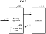
- FIG. 2 is a diagram illustrating an operation method of the security apparatus 100 according to an example embodiment.
- the process may be a process in which the security apparatus 100 is connected to the terminal 110 to perform a data processing.
- a relationship between the security apparatus 100 and the terminal 110 may be a machine to machine (M2M) connection or an Internet of Things (IoT) connection.
- M2M machine to machine
- IoT Internet of Things
- the security apparatus 100 may be used, as indicated by reference numeral 131, such that information on the security apparatus 100 is transmitted to the terminal 110.
- the terminal 110 may verify that the security apparatus 100 is the stolen or lost device and transfer, as indicated by reference numeral 133, event information to the security apparatus.
- the counteracting unit 101 may perform a processing corresponding to the security-vulnerable state. The processing may be, for example, destroying/damaging a circuit, or deactivating or changing the security information as described above.
- the security-vulnerable state may include a case in which information indicating that the security apparatus 100 is stolen or lost is previously registered on the terminal 110 or verified by the terminal 110 in real time. Furthermore, the information may be transferred, as indicated by reference numeral 135, directly to the security apparatus 100 instead of being registered on and/or referenced by the terminal 110. Similar to the example of FIG. 1 , the processing may also include a case in which the security apparatus 100 autonomously detects the security-vulnerable state and reports on the security-vulnerable state to the terminal 110.
- the detection of the security-vulnerable state may be a case in which at least one of security attacks such as destruction of a device packaging for an invasive attack, detection of an electromagnetic field for a non-invasive attack, and signal collection for a power analysis attack is detected by the security apparatus 100 or an external device (not shown) that communicates therewith.
- security attacks such as destruction of a device packaging for an invasive attack, detection of an electromagnetic field for a non-invasive attack, and signal collection for a power analysis attack is detected by the security apparatus 100 or an external device (not shown) that communicates therewith.
- FIG. 3 is a block diagram illustrating a security apparatus 201 that damages at least a portion of a circuit in a security-vulnerable state according to an example embodiment.
- a core circuit or a core chip (hereinafter, also referred to as "core circuit") 220 may perform a security function using an authentication key, for example, a secret key provided by a PUF.
- a security apparatus 201 may receive event information indicating that the security apparatus is in a security-vulnerable state such as a stolen or lost state.
- a power management integrated circuit (PMIC) 210 may apply at least one electrical shock of overvoltage and overcurrent to the security apparatus to cause a physical damage/destruction to at least a portion of the security apparatus 201 such that the core circuit may not perform the security function normally.
- PMIC power management integrated circuit
- the PMIC 210 may apply at least one of the electrical shock of overvoltage and overcurrent to the security apparatus to cause a physical damage to the security apparatus 201 such that the core circuit may not perform the security function normally.
- the electrical shock may be a method causing a breakdown of a semiconductor element in the core circuit 220 due to the application of the overvoltage.
- the electrical shock may be a method causing an electromigration in the core circuit 220 due to the application of the overcurrent. It should be understood that the type of damage or the specific result may vary depending on the application or case and that any physical damage that interferes with the normal operation of the core circuit 220 is included in such application.
- FIGS. 4 through 7 are diagrams illustrating examples of implementing a security apparatus according to an example embodiment.
- a power management circuit may apply an electrical shock to a power supply path toward a core circuit to cause a physical damage to a security apparatus such that the core circuit may not perform a security function normally.
- the security apparatus 201 may further include a metal oxide semiconductor capacitor (MOSCAP) element 230 connected in parallel with the core circuit 220 in the power supply path.
- MOSCAP metal oxide semiconductor capacitor
- the power management circuit may apply the electrical shock to the MOSCAP element 230 such that the MOSCAP element 230 forms a current path for bypassing both ends of the core circuit 220 on the power supply path.
- a normal power voltage may not be provided to the core circuit 220, which may lead to restrictions on predetermined functions of the security apparatus 201.
- FIG. 5 illustrates an application example in which an anti-fuse element is selected instead of a MOSCAP element.
- the security apparatus 201 may further include an anti-fuse element 235 connected in parallel with the core circuit 220 in the power supply path.
- a power management circuit may apply an electrical shock to the anti-fuse element 235 such that the anti-fuse element 235 forms a current path for bypassing both ends of the core circuit 220 on the power supply path.
- a result similar to the example of FIG. 4 may occur and thus, a normal power voltage may not be provided to the core circuit 220, which may prevent the security apparatus 201 from functioning normally.
- FIGS. 6 and 7 illustrate applications examples in which a fuse element 240 connected in series with the core circuit in the power supply path is selected.
- a power management circuit may apply an electrical shock to the fuse element 240 such that the fuse element 240 opens the power supply path to block a current path to the core circuit 220.
- a change in current path is different from the examples of FIGS. 4 and 5 , a normal power voltage may not be transferred to the core circuit 220, which may prevent the security apparatus 201 from functioning normally.
- the event information indicating a security-vulnerable state may include an identification code for a stolen and lost state of the security apparatus.
- the identification code may be received from at least one of an external terminal and a server connected to the security apparatus.
- the event information may also be generated by the security apparatus detecting a security attack instead of receiving from an external source.
- the security apparatus may further include a sensor (not shown) that senses a security attack on the security apparatus.
- the event information may include an identification code of an event in which the sensor senses the security attack.
- the security attack may include, but not be limited to, at least one of destruction of a device packaging for an invasive attack, detection of an electromagnetic field for a non-invasive attack, and signal collection for a power analysis attack.
- FIGS. 8 through 11 are diagrams illustrating security apparatuses changing security information to a different value in a security-vulnerable state according to example embodiments.
- a security apparatus 301 may include a key provider 310 having secure information such as an authentication key.
- the key provider may include a PUF that provides a random time-invariant digital value using a semiconductor process variation.
- the authentication key may include one of a first digital value provided directly from the PUF and a second digital value generated using the first digital value.
- the secure information may be transferred from the key provider 310 to a core circuit (not shown) such that a security function is performed.
- a control logic may disallow the authentication key to be transmitted from the key provider to the core circuit.
- the control logic may include a selector 330 that selects the authentication key provided by the key provider 310 or a key different from the authentication key based on an enable signal value.
- the selector may include, for example, a multiplexer (MUX) element.
- MUX multiplexer
- the key transferred to an outside, for example, the core circuit instead of original secure information in response to the event information being received may be provided by a random number generator 320.
- the random number generator 320 may be a true random number generator and may also be a pseudo random number generator.
- the control logic may include a gate 340 that performs an AND operation on an enable signal value and a value of the authentication key.
- the control logic may maintain the enable signal value at a logic value of "1" such that the authentication key is provided to the core circuit.
- the control logic may change the enable signal value to a logic value of "0" such that the authentication key is not provided to the core circuit.
- the control logic may include a gate 350 that performs OR operation on an enable signal value and a value of the authentication key.
- the control logic may maintain the enable signal value at a logic value of "0" such that the authentication key is provided to the core circuit.
- the control logic may change the enable signal value to a logic value of "1" such that the authentication key is not provided to the core circuit.
- the gate performing the AND operation may be replaced by a gate performing a NAND operation.
- the gate performing the OR operation may be replaced by a gate performing a NOR operation. It is to be understood that the logic circuits described in the specification may be replaced by equivalent logic circuits having the same function and that such modified circuits are understood to be included in the example embodiments of the present disclosure to the extent that they can be understood and predicted by those skilled in the art.
- FIG. 11 illustrates an application example of processing information by verifying not only whether event information is associated with a security-vulnerable state or not but also a type of the security-vulnerable state.
- a key provider 370 that provides a first identification code used for identifying a stolen state of a security apparatus, a key provider 360 that provides a second identification code used for identifying a lost state of the security apparatus, and a key provider 380 that provides a third identification code used for identifying a state in which a security attack to the security apparatus is sensed may be included.
- a control logic may use a MUX 355 to select secure information and output the selected information when the event is not received and, when the event is received, output a different identification value according to whether the event is lost, stolen, or a security attack and transfer the identification value to the core circuit.
- An authenticated side may take an appropriate action.
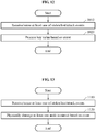
- FIG. 12 is a flowchart illustrating an operation method of a security apparatus according to an example embodiment.
- a security apparatus may receive an event that the security apparatus is in a security-vulnerable state.
- the event may be an event that the security apparatus is in at least one of stolen, lost, and attack states.
- the security apparatus may receive the event by receiving information from an external source or may autonomously sense the aforementioned states. Related description is also described above with reference to FIGS. 1 and 6 .
- the security apparatus may change secure information value of the security apparatus to a random number value or a predetermined value representing secure information. Related description is also described above with reference to FIGS. 8 through 11 .
- FIG. 13 is a flowchart illustrating an operation method of a security apparatus according to an example embodiment.
- a core circuit may perform a security function based on secure information such as an authentication key.
- event information indicating that a security apparatus is in a security-vulnerable state may be sensed or received.
- a power management circuit may apply at least one electrical shock of overvoltage and overcurrent to the security apparatus to cause a physical damage to the security apparatus such that the core circuit may not perform the security function normally.
- the electrical shock may be a shock causing a breakdown of a semiconductor element in the core circuit due to the application of the overvoltage.
- the electrical shock may be a shock causing an electromigration in the core circuit due to the application of the overcurrent. It should be understood that the type of damage or the specific result may vary depending on the application or case and that any physical damage that interferes with the normal operation of the core circuit is included in such application. Related description is also described above with reference to FIGS. 3 through 7 .
- the units described herein may be implemented using hardware components and software components.
- the hardware components may include microphones, amplifiers, band-pass filters, audio to digital converters, and processing devices.
- a processing device may be implemented using one or more general-purpose or special purpose computers, such as, for example, a processor, a controller and an arithmetic logic unit, a digital signal processor, a microcomputer, a field programmable array, a programmable logic unit, a microprocessor or any other device capable of responding to and executing instructions in a defined manner.
- the processing device may run an operating system (OS) and one or more software applications that run on the OS.
- the processing device also may access, store, manipulate, process, and create data in response to execution of the software.
- OS operating system
- a processing device may include multiple processing elements and multiple types of processing elements.
- a processing device may include multiple processors or a processor and a controller.
- different processing configurations are possible, such a parallel processors.
- the software may include a computer program, a piece of code, an instruction, or some combination thereof, for independently or collectively instructing or configuring the processing device to operate as desired.
- Software and data may be embodied permanently or temporarily in any type of machine, component, physical or virtual equipment, computer storage medium or device, or in a propagated signal wave capable of providing instructions or data to or being interpreted by the processing device.
- the software also may be distributed over network coupled computer systems so that the software is stored and executed in a distributed fashion.
- the software and data may be stored by one or more computer readable recording mediums.
- the methods according to the above-described embodiments may be recorded, stored, or fixed in one or more non-transitory computer-readable media that includes program instructions to be implemented by a computer to cause a processor to execute or perform the program instructions.
- the media may also include, alone or in combination with the program instructions, data files, data structures, and the like.
- the program instructions recorded on the media may be those specially designed and constructed, or they may be of the kind well-known and available to those having skill in the computer software arts.
- non-transitory computer-readable media examples include magnetic media such as hard disks, floppy disks, and magnetic tape; optical media such as CD ROM discs and DVDs; magneto-optical media such as optical discs; and hardware devices that are specially configured to store and perform program instructions, such as read-only memory (ROM), random access memory (RAM), flash memory, and the like.
- program instructions include both machine code, such as produced by a compiler, and files containing higher level code that may be executed by the computer using an interpreter.
- the described hardware devices may be configured to act as one or more software modules in order to perform the operations and methods described above, or vice versa.
Landscapes
- Engineering & Computer Science (AREA)
- Computer Security & Cryptography (AREA)
- Theoretical Computer Science (AREA)
- Computer Hardware Design (AREA)
- Physics & Mathematics (AREA)
- General Engineering & Computer Science (AREA)
- Computer Networks & Wireless Communication (AREA)
- Signal Processing (AREA)
- General Physics & Mathematics (AREA)
- Software Systems (AREA)
- Mathematical Physics (AREA)
- Storage Device Security (AREA)
- Computing Systems (AREA)
- Telephone Function (AREA)
Abstract
Description
- Example embodiments relate to a security apparatus and an operation method of the security apparatus, and more particularly, to a method by which a security apparatus copes with an external security attack and a stolen or lost event.
- Secure devices such as a portable communication terminal, a universal subscriber identity module (USIM), a secure digital (SD) card, a micro-SD card, and a smart card are used in a variety of application fields. Such secure device may include secure information that is also referred to as an identification key, an authentication key, and a secret key. The secure information may be used by a core circuit that performs a security authentication such as a crypto-coprocessor.
- When a security device of an authenticated user A is stolen or lost, an unauthenticated user B may obtain the security device, which may lead to a fraudulent use of the security device. As such, a counteraction may need to be taken to prevent the security device from being normally used when a stolen or lost event of the security device occurs. In a related art, when a stolen/lost report is received, an access such as disallowing a transaction may be applied to a counterpart terminal connected to a security device or a server performing a financial transaction as the counteraction.
- The secure information may be provided by a physically unclonable function (PUF). The PUF may provide an unpredictable digital value. Even when a manufacturing process is precisely designed and PUFs are manufactured in the same process, the PUFs may provide different digital values. The PUF may also be referred to as physical one-way function practically impossible to be duplicated (POWF).
- Such an unduplicable characteristic of the PUF may be applied to generate an identifier of a device for security and/or authentication. For example, the PUF may be used to provide a unique key to distinguish devices from one another.
- Korean Patent No.
10-1139630 10-0926214 -
U.S. Patent No. 8,694,856 (hereinafter, referred to as patent '856) relates to a prevention of a security attack to a PUF. The patent '856 suggests a security attack prevention that over-writes a memory value in response to a security attack using a low temperature exposure method on a PUF. - According to an aspect, there is provided a security apparatus including: a core circuit configured to perform a security function using an authentication key; and a power management circuit configured to, when event information indicating that the security apparatus is in a security-vulnerable state is received, apply at least one electrical shock of overvoltage and overcurrent to the security apparatus to cause a physical damage to the security apparatus such that the core circuit does not perform the security function normally.
- When the event information is received, the power management circuit may be configured to apply the electrical shock to the core circuit to physically damage at least a portion of the core circuit. However, embodiments are not limited thereto. For example, the power management circuit may not directly damage the core circuit in response to the event information being received.
- The power management circuit may be configured to apply the electrical shock to a power supply path to the core circuit such that the core circuit does not perform the security function normally. The security apparatus may further include a metal oxide semiconductor capacitor (MOSCAP) element connected in parallel with the core circuit in the power supply path. When the event information is received, the power management circuit may be configured to apply the electrical shock to the MOSCAP element such that the MOSCAP element forms a current path for bypassing both ends of the core circuit on the power supply path.
- The security apparatus may further include an anti-fuse element connected in parallel with the core circuit in the power supply path. When the event information is received, the power management circuit may be configured to apply the electrical shock to the anti-fuse element such that the anti-fuse element forms a current path for bypassing both ends of the core circuit on the power supply path.
- The security apparatus may further include a fuse element connected in series with the core circuit in the power supply path. When the event information is received, the power management circuit may be configured to apply the electrical shock to the fuse element such that the fuse element opens the power supply path to block a current path to the core circuit.
- The event information may include an identification code for a stolen or lost security apparatus state received from at least one of an external terminal and a server connected to the security apparatus. For example, the security apparatus may sense the stolen or lost security apparatus state and generate the event information instead of receiving the event information from an external source.
- The security apparatus may further include a sensor configured to sense a security attack on the security apparatus. The event information may include an identification code of an event in which the sensor senses the security attack. For example, the security attack may include, but not be limited to, at least one of destruction of a device packaging for an invasive attack, detection of an electromagnetic field for a non-invasive attack, and signal collection for a power analysis attack.
- According to another aspect, there is also provided a security apparatus including: a key provider having an authentication key; a core circuit configured to perform a security function using the authentication key received from the key provider; and a control logic configured to, when event information indicating that the security apparatus is in a security-vulnerable state is received, disallow the authentication key to be transmitted from the key provider to the core circuit such that the core circuit does not perform the security function normally.
- The control logic may include a selector configured to select the authentication key provided by the key provider or a random key different from the authentication key based on an enable signal value. The selector may include, for example, a multiplexer (MUX) element. When the event information is received, the control logic may be configured to change the enable signal value such that the random key is provided to the core circuit instead of the authentication key.
- The key provider may include a physically unclonable function (PUF) that provides a random time-invariant digital value using a semiconductor processing variation. The authentication key may include one of a first digital value provided directly from the PUF and a second digital value generated using the first digital value.
- The control logic may include a gate configured to perform an AND operation on an enable signal value and a value of the authentication key. The control logic may be configured to, when the event information is not received, maintain the enable signal value at a logic value of "1" such that the authentication key is provided to the core circuit. The control logic may be configured to, when the event information is received, change the enable signal value to a logic value of "0" such that the authentication key is not provided to the core circuit.
- The control logic may include a gate configured to perform an OR operation on an enable signal value and a value of the authentication key. The control logic may be configured to, when the event information is not received, maintain the enable signal value at a logic value of "0" such that the authentication key is provided to the core circuit. The control logic may be configured to, when the event information is received, change the enable signal value to a logic value of "1" such that the authentication key is not provided to the core circuit.
- The gate performing the AND operation may be replaced by a gate performing a NAND operation. The gate performing the OR operation may be replaced by a gate performing a NOR operation. It is to be understood that the logic circuits described in the specification may be replaced by equivalent logic circuits having the same function and that such modified circuits are understood to be included in the example embodiments of the present disclosure to the extent that they can be understood and predicted by those skilled in the art.
- The event information may include at least one of a first identification code used for identifying a stolen state of a security apparatus, a second identification code used for identifying a lost state of the security apparatus, and a third identification code used for identifying a state in which a security attack to the security apparatus is sensed. The control logic may include a selector configured to receive different enable signals based on the event information and output different values corresponding to the enable signals.
- According to still another aspect, there is also an operation method of a security apparatus, the method including: performing, by a core circuit, a security function using an authentication key; and applying, by a power management circuit, at least one electrical shock of overvoltage and overcurrent to the security apparatus to cause a physical damage to the security apparatus such that the core circuit does not perform the security function normally when event information indicating that the security apparatus is in a security-vulnerable state is received. When the event information is received, the power management circuit may be configured to apply the electrical shock to the core circuit to physically damage at least a portion of the core circuit. When the event information is received, the power management circuit is configured to apply the electrical shock to a power supply path to the core circuit such that the core circuit does not perform the security function normally.
-
-
FIG. 1 is a diagram illustrating a security apparatus connected to an external terminal and a server to perform data processing according to an example embodiment. -
FIG. 2 is a diagram illustrating an operation method of a security apparatus according to an example embodiment. -
FIG. 3 is a block diagram illustrating a security apparatus that damages at least a portion of a circuit in a security-vulnerable state according to an example embodiment. -
FIGS. 4 through 7 are diagrams illustrating examples of implementing a security apparatus according to an example embodiment. -
FIGS. 8 through 11 are diagrams illustrating security apparatuses changing security information to a different value in a security-vulnerable state according to example embodiments. -
FIG. 12 is a flowchart illustrating an operation method of a security apparatus according to an example embodiment. -
FIG. 13 is a flowchart illustrating an operation method of a security apparatus according to an example embodiment. - Hereinafter, example embodiments will be described in detail with reference to the accompanying drawings. It should be understood, however, that there is no intent to limit this disclosure to the particular example embodiments disclosed. Like numbers refer to like elements throughout the description of the figures.
- Terminologies used herein are defined to appropriately describe the example embodiments of the present disclosure and thus may be changed depending on a user, the intent of an operator, or a custom. Accordingly, the terminologies must be defined based on the following overall description of this specification.
- It will be further understood that terms, such as those defined in commonly used dictionaries, should be interpreted as having a meaning that is consistent with their meaning in the context of the relevant art and will not be interpreted in an idealized or overly formal sense unless expressly so defined herein.
-
FIG. 1 is a diagram illustrating asecurity apparatus 100 connected to an external terminal, for example, a terminal 110 and aserver 120 to perform data processing according to an example embodiment. Thesecurity apparatus 100 and the terminal 110 may be in contact or/or contactless connection and mutually connected through a wired or wireless communication network. The terminal 110 and theserver 120 may be mutually connected through a wired or wireless communication network. As such, thesecurity apparatus 100, the terminal 110, and theserver 120 may be connected to one another in various manners. Thesecurity apparatus 100 may be a device, for example, a personal communication terminal such as a smartphone, and a general-use computer. Also, thesecurity apparatus 100 may be a security element such as a universal subscriber identity module (USIM), a secure digital (SD) card, a micro-SD card, a smart card, and the like. - The
security apparatus 100 may have secure information which may also be referred to as, for example, an identification key, an authentication key, and a secret key. For example, the secure information is to be provided by a PUF. Also, the secure information may be used by a core circuit or a chip that performs a security authentication such as a crypto-coprocessor. Hereinafter, the terms "circuit" may refer to a circuit implemented using hardware components and software components, and may be provided in a form such as a chip, a processor, an arithmetic unit (ALU), and a part thereof. - When the security apparatus 100 a user is stolen or lost, an unauthenticated user may obtain the
security apparatus 100, which may lead to a fraudulent use of the security device. According to an example embodiment, when thesecurity apparatus 100 is stolen, lost, or in a security-vulnerable state in which an external security attack is detected, thesecurity apparatus 100 may destroy or damage at least a portion of thesecurity apparatus 100 such that a normal use is unavailable. - According to another example embodiment, when the
security apparatus 100 is in the security-vulnerable state, thesecurity apparatus 100 may change secure information used for a security authentication to another value instead of damaging a circuit thereof. Also, instead of changing a value, thesecurity apparatus 100 may output a code by which a type of security vulnerability is identified. In the present disclosure, a counteractingunit 101 may be a circuit that counteract the security-vulnerable state by, for example, destroying/damaging a circuit, or deactivating or changing the security information. The counteractingunit 101 may be understood as at least a portion of a circuit included in thesecurity apparatus 100 or a functional block of the circuit instead of a distinguishable portion in thesecurity apparatus 100. - The
security apparatus 100 may be used, as indicated byreference numeral 131, such that information on thesecurity apparatus 100 is transmitted to the terminal 110. The information may be transferred, as indicated byreference numeral 132, from the terminal 110 to theserver 120 that performs, for example, financial/security functions. When thesecurity apparatus 100 has been registered as a stolen or lost device, theserver 120 may verify that thesecurity apparatus 100 is the stolen or lost device based on the received information on the security apparatus, and respond, as indicated byreference numeral 134, to the terminal 110 using such event information. The terminal 110 may transfer, as indicated byreference numeral 133, the event information to thesecurity apparatus 100 such that the counteractingunit 101 performs a processing corresponding to the security-vulnerable state. The processing may be, for example, destroying/damaging a circuit, or deactivating or changing the security information as described above. - As further discussed below, the security-vulnerable state may include a case in which the
security apparatus 100 autonomously detects the security-vulnerable state and sends a report to theserver 120 through the terminal 110 as well as a case in which information indicating that thesecurity apparatus 100 is stolen or lost is previously registered on theserver 120 or verified by theserver 120 in real time. Thesecurity apparatus 100 may autonomously discovers/detects at least one of security attacks such as destruction of a device packaging for an invasive attack, detection of an electromagnetic field for a non-invasive attack, and signal collection for a power analysis attack and report on the detected security attack to theserver 120. In addition to the aforementioned security attacks, security attacks may include a random security attack. - Although the example of
FIG. 1 is an application involving theserver 120, it is also possible that theserver 120 is not used in such process.FIG. 2 is a diagram illustrating an operation method of thesecurity apparatus 100 according to an example embodiment. The process may be a process in which thesecurity apparatus 100 is connected to the terminal 110 to perform a data processing. A relationship between thesecurity apparatus 100 and the terminal 110 may be a machine to machine (M2M) connection or an Internet of Things (IoT) connection. - The
security apparatus 100 may be used, as indicated byreference numeral 131, such that information on thesecurity apparatus 100 is transmitted to the terminal 110. When thesecurity apparatus 100 has been registered as a stolen or lost device, the terminal 110 may verify that thesecurity apparatus 100 is the stolen or lost device and transfer, as indicated byreference numeral 133, event information to the security apparatus. The counteractingunit 101 may perform a processing corresponding to the security-vulnerable state. The processing may be, for example, destroying/damaging a circuit, or deactivating or changing the security information as described above. - The security-vulnerable state may include a case in which information indicating that the
security apparatus 100 is stolen or lost is previously registered on the terminal 110 or verified by the terminal 110 in real time. Furthermore, the information may be transferred, as indicated by reference numeral 135, directly to thesecurity apparatus 100 instead of being registered on and/or referenced by theterminal 110. Similar to the example ofFIG. 1 , the processing may also include a case in which thesecurity apparatus 100 autonomously detects the security-vulnerable state and reports on the security-vulnerable state to the terminal 110. In this example, the detection of the security-vulnerable state may be a case in which at least one of security attacks such as destruction of a device packaging for an invasive attack, detection of an electromagnetic field for a non-invasive attack, and signal collection for a power analysis attack is detected by thesecurity apparatus 100 or an external device (not shown) that communicates therewith. -
FIG. 3 is a block diagram illustrating asecurity apparatus 201 that damages at least a portion of a circuit in a security-vulnerable state according to an example embodiment. A core circuit or a core chip (hereinafter, also referred to as "core circuit") 220 may perform a security function using an authentication key, for example, a secret key provided by a PUF. Asecurity apparatus 201 may receive event information indicating that the security apparatus is in a security-vulnerable state such as a stolen or lost state. A power management integrated circuit (PMIC) 210 may apply at least one electrical shock of overvoltage and overcurrent to the security apparatus to cause a physical damage/destruction to at least a portion of thesecurity apparatus 201 such that the core circuit may not perform the security function normally. When the event information is received, thePMIC 210 may apply at least one of the electrical shock of overvoltage and overcurrent to the security apparatus to cause a physical damage to thesecurity apparatus 201 such that the core circuit may not perform the security function normally. The electrical shock may be a method causing a breakdown of a semiconductor element in thecore circuit 220 due to the application of the overvoltage. Also, the electrical shock may be a method causing an electromigration in thecore circuit 220 due to the application of the overcurrent. It should be understood that the type of damage or the specific result may vary depending on the application or case and that any physical damage that interferes with the normal operation of thecore circuit 220 is included in such application. -
FIGS. 4 through 7 are diagrams illustrating examples of implementing a security apparatus according to an example embodiment. A power management circuit may apply an electrical shock to a power supply path toward a core circuit to cause a physical damage to a security apparatus such that the core circuit may not perform a security function normally. Referring toFIG. 4 , thesecurity apparatus 201 may further include a metal oxide semiconductor capacitor (MOSCAP)element 230 connected in parallel with thecore circuit 220 in the power supply path. When event information is received, the power management circuit may apply the electrical shock to theMOSCAP element 230 such that theMOSCAP element 230 forms a current path for bypassing both ends of thecore circuit 220 on the power supply path. In this example, a normal power voltage may not be provided to thecore circuit 220, which may lead to restrictions on predetermined functions of thesecurity apparatus 201. -
FIG. 5 illustrates an application example in which an anti-fuse element is selected instead of a MOSCAP element. As shown in the drawing, thesecurity apparatus 201 may further include ananti-fuse element 235 connected in parallel with thecore circuit 220 in the power supply path. When event information is received, a power management circuit may apply an electrical shock to theanti-fuse element 235 such that theanti-fuse element 235 forms a current path for bypassing both ends of thecore circuit 220 on the power supply path. In this example, a result similar to the example ofFIG. 4 may occur and thus, a normal power voltage may not be provided to thecore circuit 220, which may prevent thesecurity apparatus 201 from functioning normally. -
FIGS. 6 and7 illustrate applications examples in which afuse element 240 connected in series with the core circuit in the power supply path is selected. When event information is received, a power management circuit may apply an electrical shock to thefuse element 240 such that thefuse element 240 opens the power supply path to block a current path to thecore circuit 220. Although a change in current path is different from the examples ofFIGS. 4 and5 , a normal power voltage may not be transferred to thecore circuit 220, which may prevent thesecurity apparatus 201 from functioning normally. - In the foregoing examples, the event information indicating a security-vulnerable state may include an identification code for a stolen and lost state of the security apparatus. Here, the identification code may be received from at least one of an external terminal and a server connected to the security apparatus. The event information may also be generated by the security apparatus detecting a security attack instead of receiving from an external source. In this example, the security apparatus may further include a sensor (not shown) that senses a security attack on the security apparatus. The event information may include an identification code of an event in which the sensor senses the security attack. The security attack may include, but not be limited to, at least one of destruction of a device packaging for an invasive attack, detection of an electromagnetic field for a non-invasive attack, and signal collection for a power analysis attack.
- In the examples described with reference to
FIGS. 4 to 7 , when the event information is received, the power management circuit may apply the electric shock to the core circuit to physically damage at least a portion of the core circuit. However, embodiments are not limited to the examples. Depending on an example, the power management circuit may not directly damage the core circuit in response to the event information being received.FIGS. 8 through 11 are diagrams illustrating security apparatuses changing security information to a different value in a security-vulnerable state according to example embodiments. - Referring to
FIG. 8 , asecurity apparatus 301 may include akey provider 310 having secure information such as an authentication key. The key provider may include a PUF that provides a random time-invariant digital value using a semiconductor process variation. The authentication key may include one of a first digital value provided directly from the PUF and a second digital value generated using the first digital value. The secure information may be transferred from thekey provider 310 to a core circuit (not shown) such that a security function is performed. - When event information indicating that the
security apparatus 301 is in a security-vulnerable state is received, a control logic may disallow the authentication key to be transmitted from the key provider to the core circuit. The control logic may include aselector 330 that selects the authentication key provided by thekey provider 310 or a key different from the authentication key based on an enable signal value. The selector may include, for example, a multiplexer (MUX) element. In this example, when the event information is received, the control logic may change the enable signal value such that the different key is provided to the core circuit instead of the authentication key. - Here, the key transferred to an outside, for example, the core circuit instead of original secure information in response to the event information being received may be provided by a
random number generator 320. Therandom number generator 320 may be a true random number generator and may also be a pseudo random number generator. - Referring to
FIG. 9 , the control logic may include agate 340 that performs an AND operation on an enable signal value and a value of the authentication key. When the event information is not received, the control logic may maintain the enable signal value at a logic value of "1" such that the authentication key is provided to the core circuit. When the event information is received, the control logic may change the enable signal value to a logic value of "0" such that the authentication key is not provided to the core circuit. - Referring to
FIG. 10 , the control logic may include agate 350 that performs OR operation on an enable signal value and a value of the authentication key. When the event information is not received, the control logic may maintain the enable signal value at a logic value of "0" such that the authentication key is provided to the core circuit. When the event information is received, the control logic may change the enable signal value to a logic value of "1" such that the authentication key is not provided to the core circuit. - The gate performing the AND operation may be replaced by a gate performing a NAND operation. The gate performing the OR operation may be replaced by a gate performing a NOR operation. It is to be understood that the logic circuits described in the specification may be replaced by equivalent logic circuits having the same function and that such modified circuits are understood to be included in the example embodiments of the present disclosure to the extent that they can be understood and predicted by those skilled in the art.
-
FIG. 11 illustrates an application example of processing information by verifying not only whether event information is associated with a security-vulnerable state or not but also a type of the security-vulnerable state. In addition to theauthentication key provider 310 including normal secure information, akey provider 370 that provides a first identification code used for identifying a stolen state of a security apparatus, akey provider 360 that provides a second identification code used for identifying a lost state of the security apparatus, and akey provider 380 that provides a third identification code used for identifying a state in which a security attack to the security apparatus is sensed may be included. - Also, a control logic may use a
MUX 355 to select secure information and output the selected information when the event is not received and, when the event is received, output a different identification value according to whether the event is lost, stolen, or a security attack and transfer the identification value to the core circuit. An authenticated side may take an appropriate action. -
FIG. 12 is a flowchart illustrating an operation method of a security apparatus according to an example embodiment. Inoperation 1010, a security apparatus may receive an event that the security apparatus is in a security-vulnerable state. The event may be an event that the security apparatus is in at least one of stolen, lost, and attack states. The security apparatus may receive the event by receiving information from an external source or may autonomously sense the aforementioned states. Related description is also described above with reference toFIGS. 1 and6 . - In
operation 1020, the security apparatus may change secure information value of the security apparatus to a random number value or a predetermined value representing secure information. Related description is also described above with reference toFIGS. 8 through 11 . -
FIG. 13 is a flowchart illustrating an operation method of a security apparatus according to an example embodiment. A core circuit may perform a security function based on secure information such as an authentication key. Inoperation 1110, event information indicating that a security apparatus is in a security-vulnerable state may be sensed or received. Inoperation 1120, a power management circuit may apply at least one electrical shock of overvoltage and overcurrent to the security apparatus to cause a physical damage to the security apparatus such that the core circuit may not perform the security function normally. The electrical shock may be a shock causing a breakdown of a semiconductor element in the core circuit due to the application of the overvoltage. Also, the electrical shock may be a shock causing an electromigration in the core circuit due to the application of the overcurrent. It should be understood that the type of damage or the specific result may vary depending on the application or case and that any physical damage that interferes with the normal operation of the core circuit is included in such application. Related description is also described above with reference toFIGS. 3 through 7 . - The units described herein may be implemented using hardware components and software components. For example, the hardware components may include microphones, amplifiers, band-pass filters, audio to digital converters, and processing devices. A processing device may be implemented using one or more general-purpose or special purpose computers, such as, for example, a processor, a controller and an arithmetic logic unit, a digital signal processor, a microcomputer, a field programmable array, a programmable logic unit, a microprocessor or any other device capable of responding to and executing instructions in a defined manner. The processing device may run an operating system (OS) and one or more software applications that run on the OS. The processing device also may access, store, manipulate, process, and create data in response to execution of the software. For purpose of simplicity, the description of a processing device is used as singular; however, one skilled in the art will appreciated that a processing device may include multiple processing elements and multiple types of processing elements. For example, a processing device may include multiple processors or a processor and a controller. In addition, different processing configurations are possible, such a parallel processors.
- The software may include a computer program, a piece of code, an instruction, or some combination thereof, for independently or collectively instructing or configuring the processing device to operate as desired. Software and data may be embodied permanently or temporarily in any type of machine, component, physical or virtual equipment, computer storage medium or device, or in a propagated signal wave capable of providing instructions or data to or being interpreted by the processing device. The software also may be distributed over network coupled computer systems so that the software is stored and executed in a distributed fashion. In particular, the software and data may be stored by one or more computer readable recording mediums.
- The methods according to the above-described embodiments may be recorded, stored, or fixed in one or more non-transitory computer-readable media that includes program instructions to be implemented by a computer to cause a processor to execute or perform the program instructions. The media may also include, alone or in combination with the program instructions, data files, data structures, and the like. The program instructions recorded on the media may be those specially designed and constructed, or they may be of the kind well-known and available to those having skill in the computer software arts. Examples of non-transitory computer-readable media include magnetic media such as hard disks, floppy disks, and magnetic tape; optical media such as CD ROM discs and DVDs; magneto-optical media such as optical discs; and hardware devices that are specially configured to store and perform program instructions, such as read-only memory (ROM), random access memory (RAM), flash memory, and the like. Examples of program instructions include both machine code, such as produced by a compiler, and files containing higher level code that may be executed by the computer using an interpreter. The described hardware devices may be configured to act as one or more software modules in order to perform the operations and methods described above, or vice versa.
- A number of example embodiments have been described above. Nevertheless, it should be understood that various modifications may be made to these example embodiments. For example, suitable results may be achieved if the described techniques are performed in a different order and/or if components in a described system, architecture, device, or circuit are combined in a different manner and/or replaced or supplemented by other components or their equivalents. Accordingly, other implementations are within the scope of the following claims.
Claims (19)
- A security apparatus comprising:a core circuit configured to perform a security function using an authentication key; anda power management circuit configured to, when event information indicating that the security apparatus is in a security-vulnerable state is received, apply at least one electrical shock of overvoltage and overcurrent to the security apparatus to cause a physical damage to the security apparatus such that the core circuit does not perform the security function normally.
- The security apparatus of claim 1, wherein when the event information is received, the power management circuit is configured to apply the electrical shock to the core circuit to physically damage at least a portion of the core circuit.
- The security apparatus of claim 1, wherein when the event information is received, the power management circuit is configured to apply the electrical shock to a power supply path to the core circuit such that the core circuit does not perform the security function normally.
- The security apparatus of claim 3, wherein the security apparatus further comprises a metal oxide semiconductor capacitor (MOSCAP) element connected in parallel with the core circuit in the power supply path, and
when the event information is received, the power management circuit is configured to apply the electrical shock to the MOSCAP element such that the MOSCAP element forms a current path for bypassing both ends of the core circuit on the power supply path. - The security apparatus of claim 3, wherein the security apparatus further comprises an anti-fuse element connected in parallel with the core circuit in the power supply path, and
when the event information is received, the power management circuit is configured to apply the electrical shock to the anti-fuse element such that the anti-fuse element forms a current path for bypassing both ends of the core circuit on the power supply path. - The security apparatus of claim 3, wherein the security apparatus further comprises a fuse element connected in series with the core circuit in the power supply path, and
when the event information is received, the power management circuit is configured to apply the electrical shock to the fuse element such that the fuse element opens the power supply path to block a current path to the core circuit. - The security apparatus of claim 1, wherein the event information includes an identification code for a stolen or lost security apparatus state received from at least one of an external terminal and a server connected to the security apparatus.
- The security apparatus of claim 1, further comprising:a sensor configured to sense a security attack on the security apparatus,wherein the event information includes an identification code of an event in which the sensor senses the security attack.
- The security apparatus of claim 8, wherein the security attack includes at least one of destruction of a device packaging for an invasive attack, detection of an electromagnetic field for a non-invasive attack, and signal collection for a power analysis attack.
- A security apparatus comprising:a key provider having an authentication key;a core circuit configured to perform a security function using the authentication key received from the key provider; anda control logic configured to, when event information indicating that the security apparatus is in a security-vulnerable state is received, disallow the authentication key to be transmitted from the key provider to the core circuit such that the core circuit does not perform the security function normally.
- The security apparatus of claim 10, wherein the control logic comprises a selector configured to select the authentication key provided by the key provider or a random key different from the authentication key based on an enable signal value, and
when the event information is received, the control logic is configured to change the enable signal value such that the random key is provided to the core circuit instead of the authentication key. - The security apparatus of claim 10, wherein the key provider comprises a physically unclonable function (PUF) that provides a random time-invariant digital value using a semiconductor processing variation, and
the authentication key includes one of a first digital value provided directly from the PUF and a second digital value generated using the first digital value. - The security apparatus of claim 10, wherein the control logic comprises a gate configured to perform an AND operation on an enable signal value and a value of the authentication key,
the control logic is configured to, when the event information is not received, maintain the enable signal value at a logic value of "1" such that the authentication key is provided to the core circuit, and
the control logic is configured to, when the event information is received, change the enable signal value to a logic value of "0" such that the authentication key is not provided to the core circuit. - The security apparatus of claim 10, wherein the control logic comprises a gate configured to perform an OR operation on an enable signal value and a value of the authentication key,
the control logic is configured to, when the event information is not received, maintain the enable signal value at a logic value of "0" such that the authentication key is provided to the core circuit, and
the control logic is configured to, when the event information is received, change the enable signal value to a logic value of "1" such that the authentication key is not provided to the core circuit. - The security apparatus of claim 10, wherein the event information includes at least one of a first identification code used for identifying a stolen state of a security apparatus, a second identification code used for identifying a lost state of the security apparatus, and a third identification code used for identifying a state in which a security attack to the security apparatus is sensed.
- The security apparatus of claim 15, wherein the control logic comprises a selector configured to receive different enable signals based on the event information and output different values corresponding to the enable signals.
- An operation method of a security apparatus, the method comprising:performing, by a core circuit, a security function using an authentication key; andapplying, by a power management circuit, at least one electrical shock of overvoltage and overcurrent to the security apparatus to cause a physical damage to the security apparatus such that the core circuit does not perform the security function normally when event information indicating that the security apparatus is in a security-vulnerable state is received.
- The operation method of claim 17, wherein when the event information is received, the power management circuit is configured to apply the electrical shock to the core circuit to physically damage at least a portion of the core circuit.
- The operation method of claim 17, wherein when the event information is received, the power management circuit is configured to apply the electrical shock to a power supply path to the core circuit such that the core circuit does not perform the security function normally.
Applications Claiming Priority (2)
| Application Number | Priority Date | Filing Date | Title |
|---|---|---|---|
| KR20150154108 | 2015-11-03 | ||
| PCT/KR2016/012584 WO2017078427A1 (en) | 2015-11-03 | 2016-11-03 | Security apparatus and operation method thereof |
Publications (3)
| Publication Number | Publication Date |
|---|---|
| EP3373188A1 true EP3373188A1 (en) | 2018-09-12 |
| EP3373188A4 EP3373188A4 (en) | 2019-03-20 |
| EP3373188B1 EP3373188B1 (en) | 2020-05-13 |
Family
ID=58662344
Family Applications (1)
| Application Number | Title | Priority Date | Filing Date |
|---|---|---|---|
| EP16862443.5A Active EP3373188B1 (en) | 2015-11-03 | 2016-11-03 | Security apparatus and operation method thereof |
Country Status (5)
| Country | Link |
|---|---|
| US (1) | US10846440B2 (en) |
| EP (1) | EP3373188B1 (en) |
| KR (1) | KR101922931B1 (en) |
| CN (1) | CN108780491A (en) |
| WO (1) | WO2017078427A1 (en) |
Families Citing this family (5)
| Publication number | Priority date | Publication date | Assignee | Title |
|---|---|---|---|---|
| KR102201217B1 (en) * | 2017-11-24 | 2021-01-12 | 한국전자통신연구원 | Self-extinguishing device and method, and semiconductor chip using the same |
| US10706179B2 (en) * | 2018-01-10 | 2020-07-07 | General Electric Company | Secure provisioning of secrets into MPSoC devices using untrusted third-party systems |
| CN110084074B (en) * | 2019-01-26 | 2021-06-22 | 鼎铉商用密码测评技术(深圳)有限公司 | Protection device and data equipment |
| US12293326B2 (en) | 2019-05-20 | 2025-05-06 | Sensormatic Electronics, LLC | Inventory event based movement of RFID tagged items |
| KR20210102740A (en) * | 2020-02-12 | 2021-08-20 | 삼성전자주식회사 | Security device generating key based on physically unclonable function and operating method of the same |
Family Cites Families (28)
| Publication number | Priority date | Publication date | Assignee | Title |
|---|---|---|---|---|
| US2011A (en) * | 1841-03-18 | Appabatxts for piling saws | ||
| US4119926A (en) * | 1977-12-08 | 1978-10-10 | Nasa | Apparatus and method for stabilized phase detection for binary signal tracking loops |
| US4534194A (en) * | 1981-03-16 | 1985-08-13 | Kadex, Incorporated | Electronic lock system |
| IL111469A0 (en) * | 1993-11-01 | 1994-12-29 | Omnipoint Corp | Despreading/demodulating direct sequence spread spectrum signals |
| US5736777A (en) * | 1995-12-29 | 1998-04-07 | Intel Corporation | Method and apparatus for fast self-destruction of a CMOS integrated circuit |
| US5790670A (en) * | 1996-07-18 | 1998-08-04 | Citicorp Development Center, Inc. | Apparatus and method for securing electronic circuitry |
| US5930175A (en) * | 1997-08-22 | 1999-07-27 | Micron Technology, Inc. | Voltage pump switch |
| WO2002095550A2 (en) * | 2001-04-25 | 2002-11-28 | Marc Elisha Grey | A security device useful for physically securing digital data storage media, and a method of use thereof |
| US7979721B2 (en) * | 2004-11-15 | 2011-07-12 | Microsoft Corporation | Enhanced packaging for PC security |
| US7502256B2 (en) * | 2004-11-30 | 2009-03-10 | Siliconsystems, Inc. | Systems and methods for reducing unauthorized data recovery from solid-state storage devices |
| US7535373B2 (en) * | 2005-07-15 | 2009-05-19 | Honeywell International, Inc. | Security techniques for electronic devices |
| US20070076513A1 (en) * | 2005-10-04 | 2007-04-05 | Nian Yang | Decoder for memory device with loading capacitor |
| KR100887551B1 (en) | 2008-09-18 | 2009-03-09 | (주)화이트클라우드 | USB with lock |
| US20100250968A1 (en) * | 2009-03-25 | 2010-09-30 | Lsi Corporation | Device for data security using user selectable one-time pad |
| KR100926214B1 (en) | 2009-04-23 | 2009-11-09 | 한양대학교 산학협력단 | Digital value generating device and method using process deviation |
| WO2011018414A2 (en) * | 2009-08-14 | 2011-02-17 | Intrinsic Id B.V. | Physically unclonable function with tamper prevention and anti-aging system |
| KR101418962B1 (en) | 2009-12-11 | 2014-07-15 | 한국전자통신연구원 | Secure device and method for preventing side chnannel attack |
| EP2337263B1 (en) * | 2009-12-17 | 2020-02-12 | Nxp B.V. | Token comprising improved physical unclonable function |
| US8249556B2 (en) | 2010-07-13 | 2012-08-21 | Google Inc. | Securing a mobile computing device |
| KR101139630B1 (en) | 2010-12-09 | 2012-05-30 | 한양대학교 산학협력단 | Apparatus and method for generating identification key |
| US20120151121A1 (en) * | 2010-12-14 | 2012-06-14 | Jose Antonio Braga | Solid State Non-Volatile Storage Drives Having Self-Erase and Self-Destruct Functionality and Related Methods |
| US9105432B2 (en) | 2011-03-31 | 2015-08-11 | Ictk Co., Ltd | Apparatus and method for generating digital value |
| US8461863B2 (en) * | 2011-04-29 | 2013-06-11 | Altera Corporation | Method and apparatus for securing a programmable device using a kill switch |
| KR101281099B1 (en) * | 2011-07-18 | 2013-07-02 | 순천향대학교 산학협력단 | An Authentication method for preventing damages from lost and stolen smart phones |
| KR101080511B1 (en) * | 2011-08-03 | 2011-11-04 | (주) 아이씨티케이 | IC chip prevents identification key leakage and its authentication method |
| EP2747335B1 (en) * | 2011-08-16 | 2017-01-11 | ICTK Co., Ltd. | Device and method for puf-based inter-device security authentication in machine-to-machine communication |
| US9081929B2 (en) * | 2012-01-06 | 2015-07-14 | New York University | Systems, processes and computer-accessible medium for providing logic encryption utilizing fault analysis |
| US9336872B2 (en) * | 2014-03-11 | 2016-05-10 | Everspin Technologies, Inc. | Nonvolatile logic and security circuits |
-
2016
- 2016-11-03 WO PCT/KR2016/012584 patent/WO2017078427A1/en not_active Ceased
- 2016-11-03 EP EP16862443.5A patent/EP3373188B1/en active Active
- 2016-11-03 CN CN201680077727.7A patent/CN108780491A/en active Pending
- 2016-11-03 US US15/773,489 patent/US10846440B2/en active Active
- 2016-11-03 KR KR1020160145773A patent/KR101922931B1/en active Active
Also Published As
| Publication number | Publication date |
|---|---|
| US10846440B2 (en) | 2020-11-24 |
| EP3373188B1 (en) | 2020-05-13 |
| US20190012487A1 (en) | 2019-01-10 |
| WO2017078427A1 (en) | 2017-05-11 |
| KR101922931B1 (en) | 2018-11-28 |
| CN108780491A (en) | 2018-11-09 |
| KR20170052507A (en) | 2017-05-12 |
| EP3373188A4 (en) | 2019-03-20 |
Similar Documents
| Publication | Publication Date | Title |
|---|---|---|
| EP3056394B1 (en) | Vehicle security network device and design method therefor | |
| US10846440B2 (en) | Security apparatus and operation method thereof | |
| TWI730941B (en) | Apparatus and method for authenticating | |
| US9292710B2 (en) | Apparatus and method for generating identification key | |
| US10165050B2 (en) | Systems and methods for diffracted data retrieval | |
| US20170251369A1 (en) | Method and device for controlling access from the device to a card via a nfc interface | |
| CN107273744B (en) | Electronic device and protection method | |
| US20170013451A1 (en) | Network locking or card locking method and device for a mobile terminal, terminal, sim card, storage media | |
| JP2018500823A (en) | Device key protection | |
| CN105847004B (en) | Method for authenticating an object by means of devices capable of mutual contactless communication, corresponding system and object | |
| KR20240024112A (en) | System and method for contactless card communication and multi-device key pair cryptographic authentication | |
| CN108270767B (en) | Data verification method | |
| EP3057031B1 (en) | Apparatus and method for generating identification key | |
| CN111901312A (en) | Method, system, equipment and readable storage medium for network access control | |
| KR101696520B1 (en) | Secure access system and operating method thereof | |
| US9693224B2 (en) | Restricting software to authorized wireless environments | |
| CN109479195B (en) | Method for managing a secure element | |
| CN104580155A (en) | Safety protection method | |
| US12568377B2 (en) | Method for IMEI verification and unauthorized device detection using control plane message and the system thereof | |
| EP3016017A1 (en) | Device comprising a sensor or an actuator protected by a secure element | |
| KR102229790B1 (en) | Method and apparatus for secure location service | |
| CN104581705A (en) | Terminal | |
| CN111212086A (en) | Computer network protection method and system | |
| JP6950861B2 (en) | Electronic information storage device, IC card, calculation decision method, and calculation decision program |
Legal Events
| Date | Code | Title | Description |
|---|---|---|---|
| STAA | Information on the status of an ep patent application or granted ep patent |
Free format text: STATUS: THE INTERNATIONAL PUBLICATION HAS BEEN MADE |
|
| PUAI | Public reference made under article 153(3) epc to a published international application that has entered the european phase |
Free format text: ORIGINAL CODE: 0009012 |
|
| STAA | Information on the status of an ep patent application or granted ep patent |
Free format text: STATUS: REQUEST FOR EXAMINATION WAS MADE |
|
| 17P | Request for examination filed |
Effective date: 20180604 |
|
| AK | Designated contracting states |
Kind code of ref document: A1 Designated state(s): AL AT BE BG CH CY CZ DE DK EE ES FI FR GB GR HR HU IE IS IT LI LT LU LV MC MK MT NL NO PL PT RO RS SE SI SK SM TR |
|
| AX | Request for extension of the european patent |
Extension state: BA ME |
|
| RAP1 | Party data changed (applicant data changed or rights of an application transferred) |
Owner name: IUCF-HYU (INDUSTRY-UNIVERSITY COOPERATION FOUNDATI Owner name: ICTK HOLDINGS CO., LTD. |
|
| DAV | Request for validation of the european patent (deleted) | ||
| DAX | Request for extension of the european patent (deleted) | ||
| A4 | Supplementary search report drawn up and despatched |
Effective date: 20190218 |
|
| RIC1 | Information provided on ipc code assigned before grant |
Ipc: H04L 9/32 20060101ALI20190212BHEP Ipc: G06F 21/88 20130101AFI20190212BHEP Ipc: G06F 21/75 20130101ALI20190212BHEP Ipc: H04L 29/06 20060101ALI20190212BHEP |
|
| GRAP | Despatch of communication of intention to grant a patent |
Free format text: ORIGINAL CODE: EPIDOSNIGR1 |
|
| STAA | Information on the status of an ep patent application or granted ep patent |
Free format text: STATUS: GRANT OF PATENT IS INTENDED |
|
| INTG | Intention to grant announced |
Effective date: 20191209 |
|
| GRAS | Grant fee paid |
Free format text: ORIGINAL CODE: EPIDOSNIGR3 |
|
| GRAA | (expected) grant |
Free format text: ORIGINAL CODE: 0009210 |
|
| STAA | Information on the status of an ep patent application or granted ep patent |
Free format text: STATUS: THE PATENT HAS BEEN GRANTED |
|
| AK | Designated contracting states |
Kind code of ref document: B1 Designated state(s): AL AT BE BG CH CY CZ DE DK EE ES FI FR GB GR HR HU IE IS IT LI LT LU LV MC MK MT NL NO PL PT RO RS SE SI SK SM TR |
|
| REG | Reference to a national code |
Ref country code: GB Ref legal event code: FG4D |
|
| REG | Reference to a national code |
Ref country code: CH Ref legal event code: EP |
|
| REG | Reference to a national code |
Ref country code: DE Ref legal event code: R096 Ref document number: 602016036570 Country of ref document: DE |
|
| REG | Reference to a national code |
Ref country code: AT Ref legal event code: REF Ref document number: 1271192 Country of ref document: AT Kind code of ref document: T Effective date: 20200615 |
|
| REG | Reference to a national code |
Ref country code: LT Ref legal event code: MG4D |
|
| REG | Reference to a national code |
Ref country code: NL Ref legal event code: MP Effective date: 20200513 |
|
| PG25 | Lapsed in a contracting state [announced via postgrant information from national office to epo] |
Ref country code: SE Free format text: LAPSE BECAUSE OF FAILURE TO SUBMIT A TRANSLATION OF THE DESCRIPTION OR TO PAY THE FEE WITHIN THE PRESCRIBED TIME-LIMIT Effective date: 20200513 Ref country code: LT Free format text: LAPSE BECAUSE OF FAILURE TO SUBMIT A TRANSLATION OF THE DESCRIPTION OR TO PAY THE FEE WITHIN THE PRESCRIBED TIME-LIMIT Effective date: 20200513 Ref country code: IS Free format text: LAPSE BECAUSE OF FAILURE TO SUBMIT A TRANSLATION OF THE DESCRIPTION OR TO PAY THE FEE WITHIN THE PRESCRIBED TIME-LIMIT Effective date: 20200913 Ref country code: PT Free format text: LAPSE BECAUSE OF FAILURE TO SUBMIT A TRANSLATION OF THE DESCRIPTION OR TO PAY THE FEE WITHIN THE PRESCRIBED TIME-LIMIT Effective date: 20200914 Ref country code: FI Free format text: LAPSE BECAUSE OF FAILURE TO SUBMIT A TRANSLATION OF THE DESCRIPTION OR TO PAY THE FEE WITHIN THE PRESCRIBED TIME-LIMIT Effective date: 20200513 Ref country code: GR Free format text: LAPSE BECAUSE OF FAILURE TO SUBMIT A TRANSLATION OF THE DESCRIPTION OR TO PAY THE FEE WITHIN THE PRESCRIBED TIME-LIMIT Effective date: 20200814 Ref country code: NO Free format text: LAPSE BECAUSE OF FAILURE TO SUBMIT A TRANSLATION OF THE DESCRIPTION OR TO PAY THE FEE WITHIN THE PRESCRIBED TIME-LIMIT Effective date: 20200813 |
|
| PG25 | Lapsed in a contracting state [announced via postgrant information from national office to epo] |
Ref country code: LV Free format text: LAPSE BECAUSE OF FAILURE TO SUBMIT A TRANSLATION OF THE DESCRIPTION OR TO PAY THE FEE WITHIN THE PRESCRIBED TIME-LIMIT Effective date: 20200513 Ref country code: RS Free format text: LAPSE BECAUSE OF FAILURE TO SUBMIT A TRANSLATION OF THE DESCRIPTION OR TO PAY THE FEE WITHIN THE PRESCRIBED TIME-LIMIT Effective date: 20200513 Ref country code: BG Free format text: LAPSE BECAUSE OF FAILURE TO SUBMIT A TRANSLATION OF THE DESCRIPTION OR TO PAY THE FEE WITHIN THE PRESCRIBED TIME-LIMIT Effective date: 20200813 Ref country code: HR Free format text: LAPSE BECAUSE OF FAILURE TO SUBMIT A TRANSLATION OF THE DESCRIPTION OR TO PAY THE FEE WITHIN THE PRESCRIBED TIME-LIMIT Effective date: 20200513 |
|
| REG | Reference to a national code |
Ref country code: AT Ref legal event code: MK05 Ref document number: 1271192 Country of ref document: AT Kind code of ref document: T Effective date: 20200513 |
|
| PG25 | Lapsed in a contracting state [announced via postgrant information from national office to epo] |
Ref country code: NL Free format text: LAPSE BECAUSE OF FAILURE TO SUBMIT A TRANSLATION OF THE DESCRIPTION OR TO PAY THE FEE WITHIN THE PRESCRIBED TIME-LIMIT Effective date: 20200513 Ref country code: AL Free format text: LAPSE BECAUSE OF FAILURE TO SUBMIT A TRANSLATION OF THE DESCRIPTION OR TO PAY THE FEE WITHIN THE PRESCRIBED TIME-LIMIT Effective date: 20200513 |
|
| PGFP | Annual fee paid to national office [announced via postgrant information from national office to epo] |
Ref country code: LU Payment date: 20201026 Year of fee payment: 5 |
|
| PG25 | Lapsed in a contracting state [announced via postgrant information from national office to epo] |
Ref country code: CZ Free format text: LAPSE BECAUSE OF FAILURE TO SUBMIT A TRANSLATION OF THE DESCRIPTION OR TO PAY THE FEE WITHIN THE PRESCRIBED TIME-LIMIT Effective date: 20200513 Ref country code: RO Free format text: LAPSE BECAUSE OF FAILURE TO SUBMIT A TRANSLATION OF THE DESCRIPTION OR TO PAY THE FEE WITHIN THE PRESCRIBED TIME-LIMIT Effective date: 20200513 Ref country code: IT Free format text: LAPSE BECAUSE OF FAILURE TO SUBMIT A TRANSLATION OF THE DESCRIPTION OR TO PAY THE FEE WITHIN THE PRESCRIBED TIME-LIMIT Effective date: 20200513 Ref country code: SM Free format text: LAPSE BECAUSE OF FAILURE TO SUBMIT A TRANSLATION OF THE DESCRIPTION OR TO PAY THE FEE WITHIN THE PRESCRIBED TIME-LIMIT Effective date: 20200513 Ref country code: EE Free format text: LAPSE BECAUSE OF FAILURE TO SUBMIT A TRANSLATION OF THE DESCRIPTION OR TO PAY THE FEE WITHIN THE PRESCRIBED TIME-LIMIT Effective date: 20200513 Ref country code: DK Free format text: LAPSE BECAUSE OF FAILURE TO SUBMIT A TRANSLATION OF THE DESCRIPTION OR TO PAY THE FEE WITHIN THE PRESCRIBED TIME-LIMIT Effective date: 20200513 Ref country code: AT Free format text: LAPSE BECAUSE OF FAILURE TO SUBMIT A TRANSLATION OF THE DESCRIPTION OR TO PAY THE FEE WITHIN THE PRESCRIBED TIME-LIMIT Effective date: 20200513 Ref country code: ES Free format text: LAPSE BECAUSE OF FAILURE TO SUBMIT A TRANSLATION OF THE DESCRIPTION OR TO PAY THE FEE WITHIN THE PRESCRIBED TIME-LIMIT Effective date: 20200513 |
|
| PGFP | Annual fee paid to national office [announced via postgrant information from national office to epo] |
Ref country code: CH Payment date: 20201117 Year of fee payment: 5 |
|
| REG | Reference to a national code |
Ref country code: DE Ref legal event code: R097 Ref document number: 602016036570 Country of ref document: DE |
|
| PG25 | Lapsed in a contracting state [announced via postgrant information from national office to epo] |
Ref country code: SK Free format text: LAPSE BECAUSE OF FAILURE TO SUBMIT A TRANSLATION OF THE DESCRIPTION OR TO PAY THE FEE WITHIN THE PRESCRIBED TIME-LIMIT Effective date: 20200513 Ref country code: PL Free format text: LAPSE BECAUSE OF FAILURE TO SUBMIT A TRANSLATION OF THE DESCRIPTION OR TO PAY THE FEE WITHIN THE PRESCRIBED TIME-LIMIT Effective date: 20200513 |
|
| PGFP | Annual fee paid to national office [announced via postgrant information from national office to epo] |
Ref country code: BE Payment date: 20201015 Year of fee payment: 5 |
|
| PLBE | No opposition filed within time limit |
Free format text: ORIGINAL CODE: 0009261 |
|
| STAA | Information on the status of an ep patent application or granted ep patent |
Free format text: STATUS: NO OPPOSITION FILED WITHIN TIME LIMIT |
|
| 26N | No opposition filed |
Effective date: 20210216 |
|
| PG25 | Lapsed in a contracting state [announced via postgrant information from national office to epo] |
Ref country code: SI Free format text: LAPSE BECAUSE OF FAILURE TO SUBMIT A TRANSLATION OF THE DESCRIPTION OR TO PAY THE FEE WITHIN THE PRESCRIBED TIME-LIMIT Effective date: 20200513 |
|
| PG25 | Lapsed in a contracting state [announced via postgrant information from national office to epo] |
Ref country code: MC Free format text: LAPSE BECAUSE OF FAILURE TO SUBMIT A TRANSLATION OF THE DESCRIPTION OR TO PAY THE FEE WITHIN THE PRESCRIBED TIME-LIMIT Effective date: 20200513 |
|
| PG25 | Lapsed in a contracting state [announced via postgrant information from national office to epo] |
Ref country code: IE Free format text: LAPSE BECAUSE OF NON-PAYMENT OF DUE FEES Effective date: 20201103 |
|
| PGFP | Annual fee paid to national office [announced via postgrant information from national office to epo] |
Ref country code: GB Payment date: 20211014 Year of fee payment: 6 Ref country code: DE Payment date: 20211019 Year of fee payment: 6 |
|
| PGFP | Annual fee paid to national office [announced via postgrant information from national office to epo] |
Ref country code: FR Payment date: 20211029 Year of fee payment: 6 |
|
| PG25 | Lapsed in a contracting state [announced via postgrant information from national office to epo] |
Ref country code: TR Free format text: LAPSE BECAUSE OF FAILURE TO SUBMIT A TRANSLATION OF THE DESCRIPTION OR TO PAY THE FEE WITHIN THE PRESCRIBED TIME-LIMIT Effective date: 20200513 Ref country code: MT Free format text: LAPSE BECAUSE OF FAILURE TO SUBMIT A TRANSLATION OF THE DESCRIPTION OR TO PAY THE FEE WITHIN THE PRESCRIBED TIME-LIMIT Effective date: 20200513 Ref country code: CY Free format text: LAPSE BECAUSE OF FAILURE TO SUBMIT A TRANSLATION OF THE DESCRIPTION OR TO PAY THE FEE WITHIN THE PRESCRIBED TIME-LIMIT Effective date: 20200513 |
|
| PG25 | Lapsed in a contracting state [announced via postgrant information from national office to epo] |
Ref country code: MK Free format text: LAPSE BECAUSE OF FAILURE TO SUBMIT A TRANSLATION OF THE DESCRIPTION OR TO PAY THE FEE WITHIN THE PRESCRIBED TIME-LIMIT Effective date: 20200513 |
|
| REG | Reference to a national code |
Ref country code: CH Ref legal event code: PL |
|
| PG25 | Lapsed in a contracting state [announced via postgrant information from national office to epo] |
Ref country code: LU Free format text: LAPSE BECAUSE OF NON-PAYMENT OF DUE FEES Effective date: 20211103 Ref country code: BE Free format text: LAPSE BECAUSE OF NON-PAYMENT OF DUE FEES Effective date: 20211130 |
|
| REG | Reference to a national code |
Ref country code: BE Ref legal event code: MM Effective date: 20211130 |
|
| PG25 | Lapsed in a contracting state [announced via postgrant information from national office to epo] |
Ref country code: LI Free format text: LAPSE BECAUSE OF NON-PAYMENT OF DUE FEES Effective date: 20211130 Ref country code: CH Free format text: LAPSE BECAUSE OF NON-PAYMENT OF DUE FEES Effective date: 20211130 |
|
| REG | Reference to a national code |
Ref country code: DE Ref legal event code: R119 Ref document number: 602016036570 Country of ref document: DE |
|
| GBPC | Gb: european patent ceased through non-payment of renewal fee |
Effective date: 20221103 |
|
| PG25 | Lapsed in a contracting state [announced via postgrant information from national office to epo] |
Ref country code: GB Free format text: LAPSE BECAUSE OF NON-PAYMENT OF DUE FEES Effective date: 20221103 Ref country code: DE Free format text: LAPSE BECAUSE OF NON-PAYMENT OF DUE FEES Effective date: 20230601 |
|
| PG25 | Lapsed in a contracting state [announced via postgrant information from national office to epo] |
Ref country code: FR Free format text: LAPSE BECAUSE OF NON-PAYMENT OF DUE FEES Effective date: 20221130 |