EP3373096A1 - System and method for controlling a work machine - Google Patents
System and method for controlling a work machine Download PDFInfo
- Publication number
- EP3373096A1 EP3373096A1 EP18160221.0A EP18160221A EP3373096A1 EP 3373096 A1 EP3373096 A1 EP 3373096A1 EP 18160221 A EP18160221 A EP 18160221A EP 3373096 A1 EP3373096 A1 EP 3373096A1
- Authority
- EP
- European Patent Office
- Prior art keywords
- work machine
- sequence
- travel
- travel paths
- material mover
- Prior art date
- Legal status (The legal status is an assumption and is not a legal conclusion. Google has not performed a legal analysis and makes no representation as to the accuracy of the status listed.)
- Withdrawn
Links
- 238000000034 method Methods 0.000 title claims description 37
- 230000007246 mechanism Effects 0.000 claims abstract description 42
- 230000008901 benefit Effects 0.000 description 4
- 238000005056 compaction Methods 0.000 description 2
- 230000006870 function Effects 0.000 description 2
- 230000003287 optical effect Effects 0.000 description 2
- 210000001956 EPC Anatomy 0.000 description 1
- 230000006978 adaptation Effects 0.000 description 1
- 230000008859 change Effects 0.000 description 1
- 238000004891 communication Methods 0.000 description 1
- 230000008878 coupling Effects 0.000 description 1
- 238000010168 coupling process Methods 0.000 description 1
- 238000005859 coupling reaction Methods 0.000 description 1
- 230000000694 effects Effects 0.000 description 1
- 238000003384 imaging method Methods 0.000 description 1
- 230000000630 rising effect Effects 0.000 description 1
- 230000000007 visual effect Effects 0.000 description 1
Images


Classifications
-
- E—FIXED CONSTRUCTIONS
- E02—HYDRAULIC ENGINEERING; FOUNDATIONS; SOIL SHIFTING
- E02F—DREDGING; SOIL-SHIFTING
- E02F3/00—Dredgers; Soil-shifting machines
- E02F3/04—Dredgers; Soil-shifting machines mechanically-driven
- E02F3/76—Graders, bulldozers, or the like with scraper plates or ploughshare-like elements; Levelling scarifying devices
- E02F3/80—Component parts
- E02F3/84—Drives or control devices therefor, e.g. hydraulic drive systems
- E02F3/841—Devices for controlling and guiding the whole machine, e.g. by feeler elements and reference lines placed exteriorly of the machine
-
- B—PERFORMING OPERATIONS; TRANSPORTING
- B60—VEHICLES IN GENERAL
- B60W—CONJOINT CONTROL OF VEHICLE SUB-UNITS OF DIFFERENT TYPE OR DIFFERENT FUNCTION; CONTROL SYSTEMS SPECIALLY ADAPTED FOR HYBRID VEHICLES; ROAD VEHICLE DRIVE CONTROL SYSTEMS FOR PURPOSES NOT RELATED TO THE CONTROL OF A PARTICULAR SUB-UNIT
- B60W10/00—Conjoint control of vehicle sub-units of different type or different function
- B60W10/20—Conjoint control of vehicle sub-units of different type or different function including control of steering systems
-
- B—PERFORMING OPERATIONS; TRANSPORTING
- B60—VEHICLES IN GENERAL
- B60W—CONJOINT CONTROL OF VEHICLE SUB-UNITS OF DIFFERENT TYPE OR DIFFERENT FUNCTION; CONTROL SYSTEMS SPECIALLY ADAPTED FOR HYBRID VEHICLES; ROAD VEHICLE DRIVE CONTROL SYSTEMS FOR PURPOSES NOT RELATED TO THE CONTROL OF A PARTICULAR SUB-UNIT
- B60W10/00—Conjoint control of vehicle sub-units of different type or different function
- B60W10/30—Conjoint control of vehicle sub-units of different type or different function including control of auxiliary equipment, e.g. air-conditioning compressors or oil pumps
-
- B—PERFORMING OPERATIONS; TRANSPORTING
- B60—VEHICLES IN GENERAL
- B60W—CONJOINT CONTROL OF VEHICLE SUB-UNITS OF DIFFERENT TYPE OR DIFFERENT FUNCTION; CONTROL SYSTEMS SPECIALLY ADAPTED FOR HYBRID VEHICLES; ROAD VEHICLE DRIVE CONTROL SYSTEMS FOR PURPOSES NOT RELATED TO THE CONTROL OF A PARTICULAR SUB-UNIT
- B60W30/00—Purposes of road vehicle drive control systems not related to the control of a particular sub-unit, e.g. of systems using conjoint control of vehicle sub-units, or advanced driver assistance systems for ensuring comfort, stability and safety or drive control systems for propelling or retarding the vehicle
- B60W30/10—Path keeping
-
- B—PERFORMING OPERATIONS; TRANSPORTING
- B60—VEHICLES IN GENERAL
- B60W—CONJOINT CONTROL OF VEHICLE SUB-UNITS OF DIFFERENT TYPE OR DIFFERENT FUNCTION; CONTROL SYSTEMS SPECIALLY ADAPTED FOR HYBRID VEHICLES; ROAD VEHICLE DRIVE CONTROL SYSTEMS FOR PURPOSES NOT RELATED TO THE CONTROL OF A PARTICULAR SUB-UNIT
- B60W40/00—Estimation or calculation of non-directly measurable driving parameters for road vehicle drive control systems not related to the control of a particular sub unit, e.g. by using mathematical models
- B60W40/02—Estimation or calculation of non-directly measurable driving parameters for road vehicle drive control systems not related to the control of a particular sub unit, e.g. by using mathematical models related to ambient conditions
-
- E—FIXED CONSTRUCTIONS
- E02—HYDRAULIC ENGINEERING; FOUNDATIONS; SOIL SHIFTING
- E02F—DREDGING; SOIL-SHIFTING
- E02F3/00—Dredgers; Soil-shifting machines
- E02F3/04—Dredgers; Soil-shifting machines mechanically-driven
- E02F3/76—Graders, bulldozers, or the like with scraper plates or ploughshare-like elements; Levelling scarifying devices
- E02F3/7609—Scraper blade mounted forwardly of the tractor on a pair of pivoting arms which are linked to the sides of the tractor, e.g. bulldozers
-
- E—FIXED CONSTRUCTIONS
- E02—HYDRAULIC ENGINEERING; FOUNDATIONS; SOIL SHIFTING
- E02F—DREDGING; SOIL-SHIFTING
- E02F9/00—Component parts of dredgers or soil-shifting machines, not restricted to one of the kinds covered by groups E02F3/00 - E02F7/00
- E02F9/20—Drives; Control devices
- E02F9/2025—Particular purposes of control systems not otherwise provided for
- E02F9/2045—Guiding machines along a predetermined path
-
- E—FIXED CONSTRUCTIONS
- E02—HYDRAULIC ENGINEERING; FOUNDATIONS; SOIL SHIFTING
- E02F—DREDGING; SOIL-SHIFTING
- E02F9/00—Component parts of dredgers or soil-shifting machines, not restricted to one of the kinds covered by groups E02F3/00 - E02F7/00
- E02F9/26—Indicating devices
- E02F9/261—Surveying the work-site to be treated
- E02F9/262—Surveying the work-site to be treated with follow-up actions to control the work tool, e.g. controller
-
- E—FIXED CONSTRUCTIONS
- E02—HYDRAULIC ENGINEERING; FOUNDATIONS; SOIL SHIFTING
- E02F—DREDGING; SOIL-SHIFTING
- E02F9/00—Component parts of dredgers or soil-shifting machines, not restricted to one of the kinds covered by groups E02F3/00 - E02F7/00
- E02F9/26—Indicating devices
- E02F9/267—Diagnosing or detecting failure of vehicles
- E02F9/268—Diagnosing or detecting failure of vehicles with failure correction follow-up actions
-
- G—PHYSICS
- G05—CONTROLLING; REGULATING
- G05D—SYSTEMS FOR CONTROLLING OR REGULATING NON-ELECTRIC VARIABLES
- G05D1/00—Control of position, course or altitude of land, water, air, or space vehicles, e.g. automatic pilot
- G05D1/0055—Control of position, course or altitude of land, water, air, or space vehicles, e.g. automatic pilot with safety arrangements
- G05D1/0061—Control of position, course or altitude of land, water, air, or space vehicles, e.g. automatic pilot with safety arrangements for transition from automatic pilot to manual pilot and vice versa
-
- G—PHYSICS
- G05—CONTROLLING; REGULATING
- G05D—SYSTEMS FOR CONTROLLING OR REGULATING NON-ELECTRIC VARIABLES
- G05D1/00—Control of position, course or altitude of land, water, air, or space vehicles, e.g. automatic pilot
- G05D1/0088—Control of position, course or altitude of land, water, air, or space vehicles, e.g. automatic pilot characterized by the autonomous decision making process, e.g. artificial intelligence, predefined behaviours
-
- G—PHYSICS
- G05—CONTROLLING; REGULATING
- G05D—SYSTEMS FOR CONTROLLING OR REGULATING NON-ELECTRIC VARIABLES
- G05D1/00—Control of position, course or altitude of land, water, air, or space vehicles, e.g. automatic pilot
- G05D1/02—Control of position or course in two dimensions
- G05D1/021—Control of position or course in two dimensions specially adapted to land vehicles
- G05D1/0212—Control of position or course in two dimensions specially adapted to land vehicles with means for defining a desired trajectory
-
- G—PHYSICS
- G05—CONTROLLING; REGULATING
- G05D—SYSTEMS FOR CONTROLLING OR REGULATING NON-ELECTRIC VARIABLES
- G05D1/00—Control of position, course or altitude of land, water, air, or space vehicles, e.g. automatic pilot
- G05D1/02—Control of position or course in two dimensions
- G05D1/021—Control of position or course in two dimensions specially adapted to land vehicles
- G05D1/0268—Control of position or course in two dimensions specially adapted to land vehicles using internal positioning means
- G05D1/0274—Control of position or course in two dimensions specially adapted to land vehicles using internal positioning means using mapping information stored in a memory device
-
- G—PHYSICS
- G05—CONTROLLING; REGULATING
- G05D—SYSTEMS FOR CONTROLLING OR REGULATING NON-ELECTRIC VARIABLES
- G05D1/00—Control of position, course or altitude of land, water, air, or space vehicles, e.g. automatic pilot
- G05D1/02—Control of position or course in two dimensions
- G05D1/021—Control of position or course in two dimensions specially adapted to land vehicles
- G05D1/0276—Control of position or course in two dimensions specially adapted to land vehicles using signals provided by a source external to the vehicle
- G05D1/0278—Control of position or course in two dimensions specially adapted to land vehicles using signals provided by a source external to the vehicle using satellite positioning signals, e.g. GPS
-
- B—PERFORMING OPERATIONS; TRANSPORTING
- B60—VEHICLES IN GENERAL
- B60W—CONJOINT CONTROL OF VEHICLE SUB-UNITS OF DIFFERENT TYPE OR DIFFERENT FUNCTION; CONTROL SYSTEMS SPECIALLY ADAPTED FOR HYBRID VEHICLES; ROAD VEHICLE DRIVE CONTROL SYSTEMS FOR PURPOSES NOT RELATED TO THE CONTROL OF A PARTICULAR SUB-UNIT
- B60W2300/00—Indexing codes relating to the type of vehicle
- B60W2300/17—Construction vehicles, e.g. graders, excavators
-
- B—PERFORMING OPERATIONS; TRANSPORTING
- B60—VEHICLES IN GENERAL
- B60W—CONJOINT CONTROL OF VEHICLE SUB-UNITS OF DIFFERENT TYPE OR DIFFERENT FUNCTION; CONTROL SYSTEMS SPECIALLY ADAPTED FOR HYBRID VEHICLES; ROAD VEHICLE DRIVE CONTROL SYSTEMS FOR PURPOSES NOT RELATED TO THE CONTROL OF A PARTICULAR SUB-UNIT
- B60W2510/00—Input parameters relating to a particular sub-units
- B60W2510/20—Steering systems
-
- B—PERFORMING OPERATIONS; TRANSPORTING
- B60—VEHICLES IN GENERAL
- B60W—CONJOINT CONTROL OF VEHICLE SUB-UNITS OF DIFFERENT TYPE OR DIFFERENT FUNCTION; CONTROL SYSTEMS SPECIALLY ADAPTED FOR HYBRID VEHICLES; ROAD VEHICLE DRIVE CONTROL SYSTEMS FOR PURPOSES NOT RELATED TO THE CONTROL OF A PARTICULAR SUB-UNIT
- B60W2520/00—Input parameters relating to overall vehicle dynamics
- B60W2520/06—Direction of travel
-
- B—PERFORMING OPERATIONS; TRANSPORTING
- B60—VEHICLES IN GENERAL
- B60W—CONJOINT CONTROL OF VEHICLE SUB-UNITS OF DIFFERENT TYPE OR DIFFERENT FUNCTION; CONTROL SYSTEMS SPECIALLY ADAPTED FOR HYBRID VEHICLES; ROAD VEHICLE DRIVE CONTROL SYSTEMS FOR PURPOSES NOT RELATED TO THE CONTROL OF A PARTICULAR SUB-UNIT
- B60W2710/00—Output or target parameters relating to a particular sub-units
- B60W2710/30—Auxiliary equipments
-
- B—PERFORMING OPERATIONS; TRANSPORTING
- B60—VEHICLES IN GENERAL
- B60W—CONJOINT CONTROL OF VEHICLE SUB-UNITS OF DIFFERENT TYPE OR DIFFERENT FUNCTION; CONTROL SYSTEMS SPECIALLY ADAPTED FOR HYBRID VEHICLES; ROAD VEHICLE DRIVE CONTROL SYSTEMS FOR PURPOSES NOT RELATED TO THE CONTROL OF A PARTICULAR SUB-UNIT
- B60W2720/00—Output or target parameters relating to overall vehicle dynamics
- B60W2720/24—Direction of travel
Definitions
- the present invention relates to systems and methods for controlling work machines, and, more particularly, to systems and methods for controlling partially or fully autonomous work machines.
- Bulldozers and other material moving work machines are frequently used at work sites to move material around the work site and alter the terrain of the work site.
- bulldozers were commandeered by an operator controlling the movement, blade position, and other aspects of the bulldozer from an operator area, such as a cabin, of the bulldozer.
- the operator uses their knowledge of the bulldozer, current worksite terrain, and desired terrain to control the actions of the bulldozer and create the desired terrain in the work site.
- a work machine with a controller system which is configured to control a steering mechanism of the work machine to follow a revised sequence of travel paths which are generated based on a comparison between an as-built map and a desired terrain map.
- the as-built map is generated based on a position of a material mover of the work machine and followed travel positions of the work machine.
- a system for moving material at a work site which includes: a work machine including a chassis, a material mover carried by the chassis and defining a material mover position, a location sensor carried by the chassis, and a steering mechanism configured to control a travel direction of the work machine; and a controller system operably coupled to the material mover, the location sensor, and the steering mechanism.
- the controller system is configured to: store a sequence of travel paths for the work machine to follow; control the steering mechanism to follow the sequence of travel paths; determine the material mover position; determine followed travel positions of the work machine based on signals from the location sensor; generate an as-built map as the work machine follows the sequence of travel paths based on the material mover position and followed travel positions; compare the as-built map to a desired terrain map; generate a revised sequence of travel paths for the work machine to follow based on the comparison between the as-built map and the desired terrain map, the revised sequence altering a material volume movement sequence of the work machine; and control the steering mechanism to follow the revised sequence of travel paths.
- a method of controlling a work machine including a chassis, a material mover carried by the chassis and defining a material mover position, a location sensor carried by the chassis, and a steering mechanism configured to control a travel direction of the work machine.
- the method is implemented by a controller system and includes: storing a sequence of travel paths for the work machine to follow; controlling the steering mechanism to follow the sequence of travel paths; determining the material mover position; determining followed travel positions of the work machine based on signals from the location sensor; generating an as-built map as the work machine follows the sequence of travel paths based on the material mover position and followed travel positions; comparing the as-built map to a desired terrain map; generating a revised sequence of travel paths for the work machine to follow based on the comparison between the as-built map and the desired terrain map, the revised sequence altering a material volume movement sequence of the work machine; and controlling the steering mechanism to follow the revised sequence of travel paths.
- An advantage of the system described herein is that the movement of the work machine can be controlled based on how the material has been shifted about a work site compared to a desired terrain map, allowing the system to account for material shift during operation and control the work machine accordingly.
- Another advantage of the system described herein is that the system can record areas where a travel anomaly has been encountered and adjust the position of the material mover based on the detected travel anomaly.
- Still another advantage of the system described herein is that the operator can override the system to alter the travel path of the work machine, with the system then generating an override sequence of travel paths to account for the override.
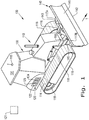
- a system 100 for moving material at a work site which generally includes a work machine 110, shown as a bulldozer, and a controller system 120.
- the controller system 120 is fully carried by the work machine 110, but such a configuration is optional and not necessary to implement the present invention.
- the controller system 120 can include one or more remote controllers 121, illustrated in dashed lines, which are not carried by the work machine 110 but are operably coupled to one or more machine controllers 122, which are carried by the work machine 110 and control various functions of the work machine 110, as will be described further herein.
- various embodiments of systems formed in accordance with the present invention may include a work machine carrying an entirety of a controller system or a work machine carrying only some of the controllers of the controller system which are operably coupled to remote controllers of the controller system.
- the bulldozer 110 includes a chassis 111, a material mover 140 carried by the chassis 111 and defining a material mover position, a location sensor 113 carried by the chassis 111, and a steering mechanism 114 which is configured to control a travel direction, illustrated as arrow T, of the bulldozer 110.
- the material mover 140 can be coupled to a c-frame 115 coupled to the chassis 111 and a mover pitch adjuster 116 which is coupled to the material mover 140 to adjust its pitch.
- the c-frame 115 can have a pair of forwardly extending arms 117A, 117B disposed on either side of the bulldozer 110 which couple to the material mover 140, shown as including a blade 141.
- the bulldozer 110 is supported on two endless tracks 118 that wrap around wheels 119 which extend laterally outward from opposite sides of the bulldozer 110.
- the wheels 119 can be coupled to the steering mechanism 114 to control the travel direction T of the bulldozer 110, as is known.
- the bulldozer 110 can also include an operator compartment 130 where an operator can access and control various systems of the bulldozer 110, such as the controller system 120, but it should be appreciated that the operator compartment 130 may be optional in configurations where the bulldozer 110 is fully autonomous and there is no need for an operator to ride with the bulldozer 110 during operation.
- the bulldozer 110 shown in Fig. 1 is merely one exemplary embodiment of a work vehicle which can be incorporated in the system 100 formed in accordance with the present invention, and can be replaced by other types of work vehicles such as a tractor-loader-backhoe (TLB), if desired.
- TLB tractor-loader-backhoe
- the material mover 140 which can include a blade 141, allows the bulldozer 110 to move a volume of material as the bulldozer 110 travels in the travel direction T.
- the blade 141 can have a curvature that allows the blade 141 to scoop up and push material forward as the bulldozer 110 travels in direction T.
- the blade 141 defines a bottom edge 142 which can define the material mover position, as the relative distance between the bottom edge 142 of the blade 141 and the ground on which the bulldozer 110 is moving defines the ability of the blade 141 to move material during travel.
- the material mover position can approximately estimate a material volume movement capacity of the material mover 140, which is described further herein.
- the material mover 140 can include a material mover position sensor 143 which is coupled to the blade 141 and outputs signals indicative of the material mover position to the controller system 120, which is described further herein.
- the material mover 140 is shown and described as being adjustable to change the material mover position, as is known, the material mover 140 can also be configured to fixedly couple to the chassis 111 and allow minimal, if any, position adjustment. Further, it should be appreciated that while the material mover 140 is shown as a curved blade 141, the material mover 140 can have any type of configuration suitable for capturing and moving material in the travel direction T of the bulldozer 110.
- the location sensor 113 which is shown as a global positioning satellite (GPS) antenna, can be placed on a top surface 131 of the operator compartment 130 and couple to the controller system 120 to determine a current position of the bulldozer 110 using any suitable configuration and method. While the location sensor 113 is shown as being placed on the top surface 131 of the operator compartment 130, the location sensor 113 can be placed anywhere on the bulldozer 110 which allows the location sensor 113 to sense the location of the bulldozer 110. In some instances, the location sensor 113 may incorporate multiple antennas to more precisely determine the position of the bulldozer 110, as is known.
- GPS global positioning satellite
- the location sensor 113 can be configured to wirelessly communicate with the controller system 120 to feed position signals of the bulldozer 110 to the controller system 120 from any location on the bulldozer 110 without the need for wires connecting the location sensor 113 to the controller system 120. It should thus be appreciated that the location sensor 113 can be placed on various locations of the bulldozer 110 and operatively coupled to the controller system 120 in a variety of ways.
- the controller system 120 can include one or more machine controllers 122 carried by the bulldozer 110 and, if desired, one or more remote controllers 121.
- the controller system 120 is operatively coupled to the material mover 140, the location sensor 113, and the steering mechanism 114 to control various functionalities of these elements.
- "operatively coupled” should be understood to mean there is a data connection between the controller system 120 and the material mover 140, the location sensor 113, and the steering mechanism 114, which can be hardwired and/or wireless, that allows data signal communication between the controller system 120 and the material mover 140, location sensor 113, and steering mechanism 114.
- the controller system 120 can include one or more memory modules 123 for storing controller instructions and one or more electronic processing circuits (EPC) 124 for executing the stored instructions, which is well-known and thus requires no further explanation.
- EPC electronic processing circuits
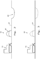
- a side view of a work site map 200 is shown with the bulldozer 110 on a ground plane GP.
- the work site map 200 has a material mound 201 rising above the ground plane GP and a ditch 202 in the ground plane GP.
- the work site map 200 can be translated into a 3-dimensional point cloud representation to allow analysis and manipulation of the work site map 200 by an EPC, such as one or more EPCs 124 of the controller system 120.
- the ground plane GP of the work site map 200 can define an X-Y Cartesian plane as utilized by known GPS systems with landmarks, such as the mound 201 and ditch 202, placed on the Cartesian plane and assigned positive or negative Z-axis values to correlate with the height (or depth) of the landmark.
- landmarks such as the mound 201 and ditch 202
- Such techniques for converting work site map surveys into translated work site maps are known in the art and are not further described herein for the sake of brevity.
- a desired terrain map 300 formed in accordance with an exemplary embodiment of the present invention is shown with the bulldozer 110 traveling on the ground plane GP.
- the desired terrain map 300 has the material mound 201, which is shown in dashed lines for illustrative purposes, removed and the ditch 202, which is also shown in dashed lines for illustrative purposes, filled.
- the resulting terrain of the desired terrain map 300 therefore, is a relatively flat ground plane GP with no terrain features extending either above or below the X-Y Cartesian plane defined by the ground plane GP.
- the desired terrain map 300 can be built from the work site map 200 by a site engineer or other professional using any type of manipulation techniques, with many such techniques being known. It should be appreciated that the shown desired terrain map 300 is for illustrative purposes only, and other desired terrain maps can be generated in accordance with various embodiments of the present invention.
- the work site map 200 can be compared to the desired terrain map 300, by the controller system 120 or other element, to determine a sequence of travel paths for the bulldozer 110 to follow, with such a sequence 410 being shown in Fig. 4 .
- the sequence 410 includes a plurality of both forward travel paths 411 and reverse travel paths 412 which are computed so that the bulldozer 110 pushes material from the mound 201 into the ditch 202 in order to reduce the height of the mound 201 and fill the ditch 202 to produce the relatively flat ground plane GP.
- a first travel path 411A is generated near a side of the mound 201 which allows the bulldozer 110 to push a volume of material from the mound 201 into the ditch 202 as the bulldozer 110 follows a straight line of the travel path 411A.
- the generated first travel path 411A can be generated so the bulldozer 110 pushes the maximum volume of material allowed while also safely operating the bulldozer 110.
- the generation of the travel paths 411, 412 can take into account parameters that define the safe and efficient operation of the bulldozer 110 including but not limited to the volume capacity of the material mover 140, the weight of the bulldozer 110, the grade of the mound 201, the turning radius of the bulldozer 110, the material compaction of the mound 201, obstacles on the work site, etc. If it is determined during travel path generation that there is not enough material in the mound 201 to fill the ditch 202, a material source 401, such as material from a dump truck, can be placed on the work site and additional travel paths 413, 414 can be generated so the bulldozer 110 can move material from the material source 401 into the ditch 202 and fully fill the ditch 202.
- a material source 401 such as material from a dump truck
- These additional travel paths 413, 414 can be generated with the same or different operating parameters to ensure the bulldozer 110 efficiently and safely moves material from the material source 401 into the ditch 202.
- the travel paths 411, 412, 413, 414 can be stored in the controller system 120 and the controller system 120 can control the steering mechanism 120 to guide the bulldozer 110 along the travel paths 411, 412, 413, 414 during forward travel of the bulldozer 110.
- an exemplary embodiment of the controller system 120 formed in accordance with the present invention is configured to generate an as-built map 500 based on followed travel positions 501 of the bulldozer 110 as well as the material mover position 142.
- the controller system 120 can determine the material mover position 142 by receiving signals from the material mover position sensor 142 of the material mover 140 corresponding to the position of the bottom edge 142 of the blade 141 and determine followed travel positions 501 of the bulldozer 110 by receiving signals from the location sensor 113.
- the controller system 120 can generate the as-built map 500 as an approximation of material volume that has been moved by the bulldozer 110 on the assumption that the material mover position 142 controls the volume of material the material mover 140 can push as the bulldozer 110 travels forward and the followed travel positions 501 control where the bulldozer 110 has pushed the material moved by the material mover 140.
- the controller system 120 can also be configured so the as-built map 500 incorporates the mound 201 and ditch 202 of the work site map 200 to determine where the material mover 140 moves material from and where the material mover 140 moves the material to during travel.
- the controller system 120 can be configured to subtract the volume of material moved by the material mover 140 from the mound 201 from the as-built map 500 when the bulldozer 110 travels over the mound 201 and add the volume of material moved by the material mover 140 into the ditch 202 to the as-built map 500 when the bulldozer 110 travels over the mound 201 and adjacent to the ditch 202, implying that the material mover 140 has dumped the carried volume of material into the ditch 202.
- the material mover 140 may not be moving material as the bulldozer 110 travels, such as a material mover position where the bottom edge 142 of the blade 141 is raised above the ground and is not contacting material.
- the controller system 120 can be configured to only factor in followed travel positions 501 in which the material mover position 142 is below a certain threshold level, indicating that the material mover 140 is actually contacting material as the bulldozer 110 travels, when generating the as-built map 500 based on the material mover position 142 and followed travel positions 501.
- the bulldozer 110 can include a resistive load sensor 510 coupled to the material mover 140 and the controller system 120 which outputs signals indicating a resistive load experienced by the material mover 140 during travel of the bulldozer 110.
- the controller system 120 can be configured to only factor in followed travel positions 501 in which the resistive load sensor 510 outputs signals above a threshold level, indicating that the material mover 140 is moving a significant volume of material, when generating the as-built map 500 based on the material mover position 142 and followed travel positions 501. It should be appreciated that the foregoing embodiments of the controller system 120 are exemplary only, and other ways of contributing to the accuracy of the as-built map 500 generation can be utilized in accordance with the present invention.
- the controller system 120 can generate the as-built map 500 to approximate the volume of material that has been moved by the material mover 140 during travel of the bulldozer 110 and where the material mover 140 has placed the volume of material. The controller system 120 can then compare the as-built map 500 to the desired terrain map 300 to determine whether the sequence of travel paths 411, 412, 413, 414 is safely and efficiently moving material from the mound 201 into the ditch 202.
- the controller system 120 can then generate a revised sequence of travel paths 601, 602, 603, 604, illustrated in Fig. 6 , to alter a material volume movement sequence of the bulldozer 110 and control the steering mechanism 114 to follow the revised sequence of travel paths 601, 602, 603, 604 so the material mover 140 dumps the entire volume of material from the mound 201 into the ditch 202.
- the controller system 120 can determine that a revised sequence of travel paths 601, 602, 603, 604 should be generated if, for example, the as-built map 500 indicates that the volume of material moved by the bulldozer 110 is not equal to the volume of the mound 201. In this sense, the comparison between the as-built map 500 and the desired terrain map 300 allows the controller system 120 to account for unexpected work site conditions which may alter the material volume movement sequence of the bulldozer 110 and appropriately control the steering mechanism 114 so the work site can be altered into the desired terrain map 300.
- the as-built map 500 also allows the controller system 120 to approximate the effect of each travel path 411, 412, 413, 414, 601, 602, 603, 604 on material volumes at the work site and determine how to efficiently and safely control the steering mechanism 114 to shape the work site into the desired terrain map 300.
- the bulldozer 110 may experience travel anomalies that make travel or operation of the bulldozer 110 unsafe.
- travel anomalies may include, but are not limited to, a bulldozer slip, an undesired fill of the material 140, and/or an undesired tilt of the bulldozer 110.
- the bulldozer 110 can include one or more operating parameter sensors, such as the previously mentioned resistive load sensor 510 and/or a tilt sensor 710, which outputs signals as the bulldozer 110 travels indicating one or more respective operating parameters of the bulldozer 110, such as the volume fill of the material mover 140 and/or a tilt of the bulldozer 110.
- the controller system 120 can be configured to detect this as a travel anomaly and control an actuator 150 linked to the material mover 140 to adjust the material mover position 142.
- the controller system 120 can attempt to correct inefficient and/or unsafe volume movement by the bulldozer 110 which is not corrected by following the revised sequence of travel paths 601, 602, 603, 604.
- the controller system 120 can be operatively coupled to the actuator 150 to adjust a height H of the material mover position 142, a rake angle ⁇ R of the material mover 140, or other position and orientation parameters of the material mover 140.
- the controller system 120 can designate an area where such inefficient and/or unsafe operation as a terrain irregularity, marked as 801 in Fig. 8 , which is taken into account while generating revised travel paths.
- the controller system 120 can be configured, for example, to either revise the sequence of travel paths in an attempt to allow the bulldozer 110 to operate safely and efficiently while traveling across the terrain irregularity 801 or, if the terrain irregularity 801 is determined to be a dangerous area, revise the sequence of travel paths to completely avoid the terrain irregularity 801.
- the controller system 120 can be configured to receive an override command from an operator riding in the bulldozer 110, which may be useful in situations where the operator sees an upcoming object or terrain hazard that is not accounted for in the travel paths 411, 412, 413, 414, 601, 602, 603, 604 the bulldozer 110 is following.
- the override command can be, for example, transmitted to the controller system 120 by the steering mechanism 114 when the operator moves a steering controller (not shown) of the steering mechanism 114 to manually control the movement of the bulldozer 110.
- the controller system 120 can record a series of override travel paths 901, 902, 903, 904 of the bulldozer 110 as the operator manually controls the steering mechanism 114. After the operator has finished manually operating the steering mechanism 114, the controller system 120 can be configured to receive a resume signal from, for example, a coupled touchscreen (not shown) which indicates the controller system 120 should resume control of the steering mechanism 114.
- the controller system 120 can be configured to generate an override sequence of travel paths 901, 902, 903, 904, 905, 906, 907, 908 which incorporate the override travel positions 901, 902, 903, 904 followed by the bulldozer 110 during the override operation and control the steering mechanism 114 to follow the override sequence of travel paths 901, 902, 903, 904, 905, 906, 907, 908, allowing the controller system 120 to control the steering mechanism 114 in a manner that presumably avoids the hazard motivating the operator to manually control the steering mechanism 114.
- the method 1000 includes storing S101 a sequence of travel paths 411, 412, 413, 414 for the bulldozer 110 to follow.
- the controller system 120 controls S102 the steering mechanism 114 to follow the sequence of travel paths 411, 412, 413, 414, and determines S103 the material mover position 142 and also determines S104 the followed travel positions 501 of the bulldozer 110 based on signals from the location sensor 113.
- the controller system 120 While the bulldozer 110 follows the sequence of travel paths 411, 412, 413, 414, the controller system 120 generates S105 an as-built map 500 based on the material mover position 142 and the followed travel positions 501.
- the controller system 120 compares S106 the as-built map 500 to a desired terrain map 300 and, based on the comparison S106, generates S107 a revised sequence of travel paths 601, 602, 603, 604 which alters a material volume movement sequence of the bulldozer 110.
- the controller system then controls S108 the steering mechanism 114 to follow the revised sequence of travel paths 601, 602, 603, 604.
- the method 1100 substantially comprises the method 1000, with the controller system 120 also detecting S111 a travel anomaly from an output signal of at least one operating parameter sensor 510, 710 of the bulldozer 110 as the work machine 110 follows the revised sequence of travel paths 601, 602, 603, 604.
- the controller system 120 can adjust S112 the material mover position 142 of the material mover 140 based on the detected travel anomaly.
- the detected travel anomaly can be, for example, a work machine slip, an undesired fill of the material mover 140, and/or an undesired tilt of the bulldozer 110.
- the controller system 120 can adjust S112, for example, the height H and/or rake angle ⁇ R of the material mover 120 based on the detected travel anomaly.
- the method 1200 substantially comprises the method 1000, with the controller system 120 also receiving S121 an override command, generating S122 an override sequence of travel paths 901, 902, 903, 904, 905, 906, 907, 908 subsequently to receiving S121 the override command, and controlling S123 the steering mechanism 114 to follow the override sequence of travel paths 901, 902, 903, 904, 905, 906, 907, 908.
- the method 1300 substantially comprises the method 1000, with the controller system 120 also detecting S131 a terrain irregularity 801 as the bulldozer 110 follows the sequence of travel paths 411, 412, 413, 414.
- the controller system 120 then takes into account the terrain irregularity 801 while generating S107 the revised sequence of travel paths 601, 602, 603, 604 for the bulldozer 110 to follow.
- a respective controller system 120 which may include one or more controllers 121, 122, upon loading and executing software code or instructions which are tangibly stored on a tangible computer readable medium, such as on a magnetic medium, e.g., a computer hard drive, an optical medium, e.g., an optical disc, solid-state memory, e.g., flash memory, or other storage media known in the art.
- a tangible computer readable medium such as on a magnetic medium, e.g., a computer hard drive, an optical medium, e.g., an optical disc, solid-state memory, e.g., flash memory, or other storage media known in the art.
- any of the functionality performed by the controller system 120 described herein, such as the methods 1000, 1100, 1200, and 1300 is implemented in software code or instructions which are tangibly stored on a tangible computer readable medium.
- the controller system 120 may perform any of the functionality of the controller system 120 described herein, including any steps of the methods 1000, 1100, 1200
- software code or “code” used herein refers to any instructions or set of instructions that influence the operation of a computer or controller. They may exist in a computer-executable form, such as machine code, which is the set of instructions and data directly executed by a computer's central processing unit or by a controller, a human-understandable form, such as source code, which may be compiled in order to be executed by a computer's central processing unit or by a controller, or an intermediate form, such as object code, which is produced by a compiler.
- the term "software code” or “code” also includes any human-understandable computer instructions or set of instructions, e.g., a script, that may be executed on the fly with the aid of an interpreter executed by a computer's central processing unit, by a controller, or by a controller system.
Abstract
Description
- The present invention relates to systems and methods for controlling work machines, and, more particularly, to systems and methods for controlling partially or fully autonomous work machines.
- Bulldozers and other material moving work machines are frequently used at work sites to move material around the work site and alter the terrain of the work site. Traditionally, bulldozers were commandeered by an operator controlling the movement, blade position, and other aspects of the bulldozer from an operator area, such as a cabin, of the bulldozer. The operator uses their knowledge of the bulldozer, current worksite terrain, and desired terrain to control the actions of the bulldozer and create the desired terrain in the work site.
- As more functions and controls have been introduced to material moving work machines, it has become more difficult for operators to effectively keep track of and control all operating parameters of work machines. Further, operators may not be able to adequately control the work machine to deal with issues that develop as the work machine moves terrains, such as the work machine slipping due to unpredictable material movement as the work machine moves material. Operators also typically control the work machines based on their "feel" for the machine and its operation, which leaves room for significant inefficiencies.
- To address some of the issues associated with operators manually controlling material moving work machines, autonomous work machines have been developed which provide varying degrees of autonomy to the operation of the work vehicle through a controller system. One example of such a system is described in
U.S. Patent No. 7,865,285 to Price et al. , which incorporates a machine mounted stereo imaging apparatus to assist in autonomously controlling the movement of the work machine based on a desired terrain map of the work site compared to a current map of the work site which is generated from one or more images of the work site. One particular problem with the system described by Price et al. is that relying on visual images of the work site to generate the current map of the work site does not take into account how the material may shift while being moved by the work machine. If material shifts in such a way that obstructs the visualizing element(s) of the work vehicle, the current map of the work site will be inaccurate without an additional image from another vantage point, which complicates the system and increases the cost. Further, such a system cannot adequately predict and compensate for material shift that naturally occurs as the work machine moves material across the worksite. - What is needed in the art is a work machine which can address some of the previously described issues which are known in the prior art.
- In accordance with an aspect of the present invention, there is provided a work machine with a controller system which is configured to control a steering mechanism of the work machine to follow a revised sequence of travel paths which are generated based on a comparison between an as-built map and a desired terrain map. The as-built map is generated based on a position of a material mover of the work machine and followed travel positions of the work machine.
- In accordance with another aspect of the present invention, there is provided a system for moving material at a work site which includes: a work machine including a chassis, a material mover carried by the chassis and defining a material mover position, a location sensor carried by the chassis, and a steering mechanism configured to control a travel direction of the work machine; and a controller system operably coupled to the material mover, the location sensor, and the steering mechanism. The controller system is configured to: store a sequence of travel paths for the work machine to follow; control the steering mechanism to follow the sequence of travel paths; determine the material mover position; determine followed travel positions of the work machine based on signals from the location sensor; generate an as-built map as the work machine follows the sequence of travel paths based on the material mover position and followed travel positions; compare the as-built map to a desired terrain map; generate a revised sequence of travel paths for the work machine to follow based on the comparison between the as-built map and the desired terrain map, the revised sequence altering a material volume movement sequence of the work machine; and control the steering mechanism to follow the revised sequence of travel paths.
- In accordance with yet another aspect of the present invention, there is provided a method of controlling a work machine including a chassis, a material mover carried by the chassis and defining a material mover position, a location sensor carried by the chassis, and a steering mechanism configured to control a travel direction of the work machine. The method is implemented by a controller system and includes: storing a sequence of travel paths for the work machine to follow; controlling the steering mechanism to follow the sequence of travel paths; determining the material mover position; determining followed travel positions of the work machine based on signals from the location sensor; generating an as-built map as the work machine follows the sequence of travel paths based on the material mover position and followed travel positions; comparing the as-built map to a desired terrain map; generating a revised sequence of travel paths for the work machine to follow based on the comparison between the as-built map and the desired terrain map, the revised sequence altering a material volume movement sequence of the work machine; and controlling the steering mechanism to follow the revised sequence of travel paths.
- An advantage of the system described herein is that the movement of the work machine can be controlled based on how the material has been shifted about a work site compared to a desired terrain map, allowing the system to account for material shift during operation and control the work machine accordingly.
- Another advantage of the system described herein is that the system can record areas where a travel anomaly has been encountered and adjust the position of the material mover based on the detected travel anomaly.
- Still another advantage of the system described herein is that the operator can override the system to alter the travel path of the work machine, with the system then generating an override sequence of travel paths to account for the override.
- The above-mentioned and other features and advantages of this invention, and the manner of attaining them, will become more apparent and the invention will be better understood by reference to the following description of exemplary embodiments of the invention taken in conjunction with the accompanying drawings, wherein:
-
Fig. 1 is a perspective view of a work machine and controller system formed in accordance with an exemplary embodiment of the present invention; -
Fig. 2 is a side view of the work machine shown inFig. 1 at a work site; -
Fig. 3 is a generated side view of the work machine shown inFig. 1 on a desired terrain map which is generated to control the work machine; -
Fig. 4 is a top view of a map illustrating operation of the controller system in accordance with an exemplary embodiment of the present invention to control the work machine shown inFig. 1 and create the desired terrain map shown inFig. 3 ; -
Fig. 5 is a generated as-built map formed in accordance with an exemplary embodiment of the present invention; -
Fig. 6 is a top view of a map illustrating a revised sequence of travel paths generated by the controller system in accordance with an exemplary embodiment of the present invention; -
Fig. 7 is a side view of the work machine shown inFig. 1 with the controller system adjusting a material mover position in accordance with an exemplary embodiment of the present invention; -
Fig. 8 is a top view of a work site which has a terrain irregularity present; -
Fig. 9 is a top view of a map illustrating an override sequence of travel paths generated by the controller system in accordance with an exemplary embodiment of the present invention; -
Fig. 10 is a flow chart illustrating an exemplary embodiment of a method in accordance with the present invention; -
Fig. 11 is a flow chart illustrating another exemplary embodiment of a method in accordance with the present invention; -
Fig. 12 is a flow chart illustrating yet another exemplary embodiment of a method in accordance with the present invention; and -
Fig. 13 is a flow chart illustrating yet another exemplary embodiment of a method in accordance with the present invention. - Corresponding reference characters indicate corresponding parts throughout the several views. The exemplifications set out herein illustrate embodiments of the invention and such exemplifications are not to be construed as limiting the scope of the invention in any manner.
- Referring now to the drawings, and more particularly to
Fig. 1 , there is shown an exemplary embodiment of asystem 100 for moving material at a work site which generally includes awork machine 110, shown as a bulldozer, and acontroller system 120. As shown inFig. 1 , thecontroller system 120 is fully carried by thework machine 110, but such a configuration is optional and not necessary to implement the present invention. For example, thecontroller system 120 can include one or moreremote controllers 121, illustrated in dashed lines, which are not carried by thework machine 110 but are operably coupled to one ormore machine controllers 122, which are carried by thework machine 110 and control various functions of thework machine 110, as will be described further herein. It should thus be appreciated that various embodiments of systems formed in accordance with the present invention may include a work machine carrying an entirety of a controller system or a work machine carrying only some of the controllers of the controller system which are operably coupled to remote controllers of the controller system. - The
bulldozer 110, as shown, includes achassis 111, amaterial mover 140 carried by thechassis 111 and defining a material mover position, alocation sensor 113 carried by thechassis 111, and asteering mechanism 114 which is configured to control a travel direction, illustrated as arrow T, of thebulldozer 110. As shown, thematerial mover 140 can be coupled to a c-frame 115 coupled to thechassis 111 and amover pitch adjuster 116 which is coupled to thematerial mover 140 to adjust its pitch. The c-frame 115 can have a pair of forwardly extendingarms bulldozer 110 which couple to the material mover 140, shown as including ablade 141. Thebulldozer 110 is supported on twoendless tracks 118 that wrap aroundwheels 119 which extend laterally outward from opposite sides of thebulldozer 110. Thewheels 119 can be coupled to thesteering mechanism 114 to control the travel direction T of thebulldozer 110, as is known. Thebulldozer 110 can also include anoperator compartment 130 where an operator can access and control various systems of thebulldozer 110, such as thecontroller system 120, but it should be appreciated that theoperator compartment 130 may be optional in configurations where thebulldozer 110 is fully autonomous and there is no need for an operator to ride with thebulldozer 110 during operation. It should be appreciated that thebulldozer 110 shown inFig. 1 is merely one exemplary embodiment of a work vehicle which can be incorporated in thesystem 100 formed in accordance with the present invention, and can be replaced by other types of work vehicles such as a tractor-loader-backhoe (TLB), if desired. - The
material mover 140, which can include ablade 141, allows thebulldozer 110 to move a volume of material as thebulldozer 110 travels in the travel direction T. As shown, theblade 141 can have a curvature that allows theblade 141 to scoop up and push material forward as thebulldozer 110 travels in direction T. Theblade 141 defines abottom edge 142 which can define the material mover position, as the relative distance between thebottom edge 142 of theblade 141 and the ground on which thebulldozer 110 is moving defines the ability of theblade 141 to move material during travel. If thebottom edge 142 is raised above a ground plane, for example, theblade 141 may not be able to access and push as much material compared to when thebottom edge 142 is level or below the ground plane. In this sense, the material mover position can approximately estimate a material volume movement capacity of thematerial mover 140, which is described further herein. In order to monitor the material mover position, thematerial mover 140 can include a materialmover position sensor 143 which is coupled to theblade 141 and outputs signals indicative of the material mover position to thecontroller system 120, which is described further herein. While thematerial mover 140 is shown and described as being adjustable to change the material mover position, as is known, thematerial mover 140 can also be configured to fixedly couple to thechassis 111 and allow minimal, if any, position adjustment. Further, it should be appreciated that while thematerial mover 140 is shown as acurved blade 141, thematerial mover 140 can have any type of configuration suitable for capturing and moving material in the travel direction T of thebulldozer 110. - The
location sensor 113, which is shown as a global positioning satellite (GPS) antenna, can be placed on atop surface 131 of theoperator compartment 130 and couple to thecontroller system 120 to determine a current position of thebulldozer 110 using any suitable configuration and method. While thelocation sensor 113 is shown as being placed on thetop surface 131 of theoperator compartment 130, thelocation sensor 113 can be placed anywhere on thebulldozer 110 which allows thelocation sensor 113 to sense the location of thebulldozer 110. In some instances, thelocation sensor 113 may incorporate multiple antennas to more precisely determine the position of thebulldozer 110, as is known. Further, while thelocation sensor 113 is shown as being hard-wired to thecontroller system 120, thelocation sensor 113 can be configured to wirelessly communicate with thecontroller system 120 to feed position signals of thebulldozer 110 to thecontroller system 120 from any location on thebulldozer 110 without the need for wires connecting thelocation sensor 113 to thecontroller system 120. It should thus be appreciated that thelocation sensor 113 can be placed on various locations of thebulldozer 110 and operatively coupled to thecontroller system 120 in a variety of ways. - The
controller system 120, as described previously, can include one ormore machine controllers 122 carried by thebulldozer 110 and, if desired, one or moreremote controllers 121. Thecontroller system 120 is operatively coupled to thematerial mover 140, thelocation sensor 113, and thesteering mechanism 114 to control various functionalities of these elements. As used herein, "operatively coupled" should be understood to mean there is a data connection between thecontroller system 120 and thematerial mover 140, thelocation sensor 113, and thesteering mechanism 114, which can be hardwired and/or wireless, that allows data signal communication between thecontroller system 120 and thematerial mover 140,location sensor 113, andsteering mechanism 114. Such operative coupling allows thecontroller system 120 to analyze signals from the coupled elements and adjust the operation of the coupled elements, as will be described further herein. Thecontroller system 120 can include one ormore memory modules 123 for storing controller instructions and one or more electronic processing circuits (EPC) 124 for executing the stored instructions, which is well-known and thus requires no further explanation. - Referring now to
Fig. 2 , a side view of a work site map 200 is shown with thebulldozer 110 on a ground plane GP. As can be seen, the work site map 200 has amaterial mound 201 rising above the ground plane GP and aditch 202 in the ground plane GP. In accordance with known techniques, the work site map 200 can be translated into a 3-dimensional point cloud representation to allow analysis and manipulation of the work site map 200 by an EPC, such as one or more EPCs 124 of thecontroller system 120. When translated, the ground plane GP of the work site map 200 can define an X-Y Cartesian plane as utilized by known GPS systems with landmarks, such as themound 201 and ditch 202, placed on the Cartesian plane and assigned positive or negative Z-axis values to correlate with the height (or depth) of the landmark. Such techniques for converting work site map surveys into translated work site maps are known in the art and are not further described herein for the sake of brevity. - Referring now to
Fig. 3 , a desiredterrain map 300 formed in accordance with an exemplary embodiment of the present invention is shown with thebulldozer 110 traveling on the ground plane GP. As can be seen, the desiredterrain map 300 has thematerial mound 201, which is shown in dashed lines for illustrative purposes, removed and theditch 202, which is also shown in dashed lines for illustrative purposes, filled. The resulting terrain of the desiredterrain map 300, therefore, is a relatively flat ground plane GP with no terrain features extending either above or below the X-Y Cartesian plane defined by the ground plane GP. The desiredterrain map 300 can be built from the work site map 200 by a site engineer or other professional using any type of manipulation techniques, with many such techniques being known. It should be appreciated that the shown desiredterrain map 300 is for illustrative purposes only, and other desired terrain maps can be generated in accordance with various embodiments of the present invention. - Once the desired
terrain map 300 is generated, the work site map 200 can be compared to the desiredterrain map 300, by thecontroller system 120 or other element, to determine a sequence of travel paths for thebulldozer 110 to follow, with such asequence 410 being shown inFig. 4 . As can be seen, thesequence 410 includes a plurality of bothforward travel paths 411 andreverse travel paths 412 which are computed so that thebulldozer 110 pushes material from themound 201 into theditch 202 in order to reduce the height of themound 201 and fill theditch 202 to produce the relatively flat ground plane GP. As can be seen, afirst travel path 411A is generated near a side of themound 201 which allows thebulldozer 110 to push a volume of material from themound 201 into theditch 202 as thebulldozer 110 follows a straight line of thetravel path 411A. The generatedfirst travel path 411A can be generated so thebulldozer 110 pushes the maximum volume of material allowed while also safely operating thebulldozer 110. The generation of thetravel paths bulldozer 110 including but not limited to the volume capacity of thematerial mover 140, the weight of thebulldozer 110, the grade of themound 201, the turning radius of thebulldozer 110, the material compaction of themound 201, obstacles on the work site, etc. If it is determined during travel path generation that there is not enough material in themound 201 to fill theditch 202, amaterial source 401, such as material from a dump truck, can be placed on the work site andadditional travel paths bulldozer 110 can move material from thematerial source 401 into theditch 202 and fully fill theditch 202. Theseadditional travel paths bulldozer 110 efficiently and safely moves material from thematerial source 401 into theditch 202. Once thetravel paths travel paths controller system 120 and thecontroller system 120 can control thesteering mechanism 120 to guide thebulldozer 110 along thetravel paths bulldozer 110. - Prior to or during the
bulldozer 110 following thetravel paths travel paths bulldozer 110 in a safe and/or efficient manner. For example, there may be an unexpected compaction of material in themound 201 that is not accounted for during generation of thetravel paths material mover 140 as thebulldozer 110 travels through themound 201. To account for such unexpected conditions, and referring now toFig. 5 , an exemplary embodiment of thecontroller system 120 formed in accordance with the present invention is configured to generate an as-builtmap 500 based on followedtravel positions 501 of thebulldozer 110 as well as thematerial mover position 142. To generate the as-builtmap 500, thecontroller system 120 can determine thematerial mover position 142 by receiving signals from the materialmover position sensor 142 of thematerial mover 140 corresponding to the position of thebottom edge 142 of theblade 141 and determine followedtravel positions 501 of thebulldozer 110 by receiving signals from thelocation sensor 113. Based on these signals, thecontroller system 120 can generate the as-builtmap 500 as an approximation of material volume that has been moved by thebulldozer 110 on the assumption that thematerial mover position 142 controls the volume of material thematerial mover 140 can push as thebulldozer 110 travels forward and thefollowed travel positions 501 control where thebulldozer 110 has pushed the material moved by thematerial mover 140. Thecontroller system 120 can also be configured so the as-builtmap 500 incorporates themound 201 and ditch 202 of the work site map 200 to determine where thematerial mover 140 moves material from and where thematerial mover 140 moves the material to during travel. For example, thecontroller system 120 can be configured to subtract the volume of material moved by thematerial mover 140 from themound 201 from the as-builtmap 500 when thebulldozer 110 travels over themound 201 and add the volume of material moved by thematerial mover 140 into theditch 202 to the as-builtmap 500 when thebulldozer 110 travels over themound 201 and adjacent to theditch 202, implying that thematerial mover 140 has dumped the carried volume of material into theditch 202. - In certain material mover positions, the
material mover 140 may not be moving material as thebulldozer 110 travels, such as a material mover position where thebottom edge 142 of theblade 141 is raised above the ground and is not contacting material. To more accurately generate the as-builtmap 500, thecontroller system 120 can be configured to only factor infollowed travel positions 501 in which thematerial mover position 142 is below a certain threshold level, indicating that thematerial mover 140 is actually contacting material as thebulldozer 110 travels, when generating the as-builtmap 500 based on thematerial mover position 142 and followed travel positions 501. Alternatively, or in addition, thebulldozer 110 can include aresistive load sensor 510 coupled to thematerial mover 140 and thecontroller system 120 which outputs signals indicating a resistive load experienced by thematerial mover 140 during travel of thebulldozer 110. In such an embodiment, thecontroller system 120 can be configured to only factor infollowed travel positions 501 in which theresistive load sensor 510 outputs signals above a threshold level, indicating that thematerial mover 140 is moving a significant volume of material, when generating the as-builtmap 500 based on thematerial mover position 142 and followed travel positions 501. It should be appreciated that the foregoing embodiments of thecontroller system 120 are exemplary only, and other ways of contributing to the accuracy of the as-builtmap 500 generation can be utilized in accordance with the present invention. - While the
bulldozer 110 travels across a work site, thecontroller system 120 can generate the as-builtmap 500 to approximate the volume of material that has been moved by thematerial mover 140 during travel of thebulldozer 110 and where thematerial mover 140 has placed the volume of material. Thecontroller system 120 can then compare the as-builtmap 500 to the desiredterrain map 300 to determine whether the sequence oftravel paths mound 201 into theditch 202. If, for example, the comparison between the as-builtmap 500 and the desiredterrain map 300 indicates that thebulldozer 110 has not moved the entire volume of the material from themound 201 into theditch 202, thecontroller system 120 can then generate a revised sequence oftravel paths Fig. 6 , to alter a material volume movement sequence of thebulldozer 110 and control thesteering mechanism 114 to follow the revised sequence oftravel paths material mover 140 dumps the entire volume of material from themound 201 into theditch 202. Thecontroller system 120 can determine that a revised sequence oftravel paths map 500 indicates that the volume of material moved by thebulldozer 110 is not equal to the volume of themound 201. In this sense, the comparison between the as-builtmap 500 and the desiredterrain map 300 allows thecontroller system 120 to account for unexpected work site conditions which may alter the material volume movement sequence of thebulldozer 110 and appropriately control thesteering mechanism 114 so the work site can be altered into the desiredterrain map 300. The as-builtmap 500 also allows thecontroller system 120 to approximate the effect of eachtravel path steering mechanism 114 to shape the work site into the desiredterrain map 300. - As the
bulldozer 110 travels and moves material, thebulldozer 110 may experience travel anomalies that make travel or operation of thebulldozer 110 unsafe. Such travel anomalies may include, but are not limited to, a bulldozer slip, an undesired fill of thematerial 140, and/or an undesired tilt of thebulldozer 110. To safely and efficiently operate thebulldozer 110, and referring now toFig. 7 , thebulldozer 110 can include one or more operating parameter sensors, such as the previously mentionedresistive load sensor 510 and/or atilt sensor 710, which outputs signals as thebulldozer 110 travels indicating one or more respective operating parameters of thebulldozer 110, such as the volume fill of thematerial mover 140 and/or a tilt of thebulldozer 110. When the output signal(s) from the operating parameter sensor(s) 510, 710 are outside of an acceptable operating range as thebulldozer 110 follows the revised sequence oftravel paths controller system 120 can be configured to detect this as a travel anomaly and control anactuator 150 linked to thematerial mover 140 to adjust thematerial mover position 142. By adjusting thematerial mover position 140 as thebulldozer 110 is already following the revised sequence oftravel paths bulldozer 110, thecontroller system 120 can attempt to correct inefficient and/or unsafe volume movement by thebulldozer 110 which is not corrected by following the revised sequence oftravel paths controller system 120 can be operatively coupled to theactuator 150 to adjust a height H of thematerial mover position 142, a rake angle αR of thematerial mover 140, or other position and orientation parameters of thematerial mover 140. - If the
controller system 120 detects inefficient and/or unsafe operation of thebulldozer 110 while thebulldozer 110 follows the initially generatedtravel paths controller system 120 can designate an area where such inefficient and/or unsafe operation as a terrain irregularity, marked as 801 inFig. 8 , which is taken into account while generating revised travel paths. Thecontroller system 120 can be configured, for example, to either revise the sequence of travel paths in an attempt to allow thebulldozer 110 to operate safely and efficiently while traveling across theterrain irregularity 801 or, if theterrain irregularity 801 is determined to be a dangerous area, revise the sequence of travel paths to completely avoid theterrain irregularity 801. - Referring now to
Fig. 9 , thecontroller system 120 can be configured to receive an override command from an operator riding in thebulldozer 110, which may be useful in situations where the operator sees an upcoming object or terrain hazard that is not accounted for in thetravel paths bulldozer 110 is following. The override command can be, for example, transmitted to thecontroller system 120 by thesteering mechanism 114 when the operator moves a steering controller (not shown) of thesteering mechanism 114 to manually control the movement of thebulldozer 110. While the operator manually steers thesteering mechanism 114, thecontroller system 120 can record a series ofoverride travel paths bulldozer 110 as the operator manually controls thesteering mechanism 114. After the operator has finished manually operating thesteering mechanism 114, thecontroller system 120 can be configured to receive a resume signal from, for example, a coupled touchscreen (not shown) which indicates thecontroller system 120 should resume control of thesteering mechanism 114. Upon receiving the resume signal, thecontroller system 120 can be configured to generate an override sequence oftravel paths override travel positions bulldozer 110 during the override operation and control thesteering mechanism 114 to follow the override sequence oftravel paths controller system 120 to control thesteering mechanism 114 in a manner that presumably avoids the hazard motivating the operator to manually control thesteering mechanism 114. - Referring now to
Fig. 10 , an exemplary embodiment of amethod 1000 implemented by thecontroller system 120 in accordance with the present invention is shown. Themethod 1000 includes storing S101 a sequence oftravel paths bulldozer 110 to follow. Thecontroller system 120 controls S102 thesteering mechanism 114 to follow the sequence oftravel paths material mover position 142 and also determines S104 thefollowed travel positions 501 of thebulldozer 110 based on signals from thelocation sensor 113. While thebulldozer 110 follows the sequence oftravel paths controller system 120 generates S105 an as-builtmap 500 based on thematerial mover position 142 and the followed travel positions 501. Thecontroller system 120 compares S106 the as-builtmap 500 to a desiredterrain map 300 and, based on the comparison S106, generates S107 a revised sequence oftravel paths bulldozer 110. The controller system then controls S108 thesteering mechanism 114 to follow the revised sequence oftravel paths - Referring now to
Fig. 11 , another exemplary embodiment of amethod 1100 implemented by thecontroller system 120 in accordance with the present invention is shown. As can be seen, themethod 1100 substantially comprises themethod 1000, with thecontroller system 120 also detecting S111 a travel anomaly from an output signal of at least oneoperating parameter sensor bulldozer 110 as thework machine 110 follows the revised sequence oftravel paths controller system 120 can adjust S112 thematerial mover position 142 of thematerial mover 140 based on the detected travel anomaly. The detected travel anomaly can be, for example, a work machine slip, an undesired fill of thematerial mover 140, and/or an undesired tilt of thebulldozer 110. Thecontroller system 120 can adjust S112, for example, the height H and/or rake angle αR of thematerial mover 120 based on the detected travel anomaly. - Referring now to
Fig. 12 , another exemplary embodiment of amethod 1200 implemented by thecontroller system 120 in accordance with the present invention is shown. As can be seen, themethod 1200 substantially comprises themethod 1000, with thecontroller system 120 also receiving S121 an override command, generating S122 an override sequence oftravel paths steering mechanism 114 to follow the override sequence oftravel paths - Referring now to
Fig. 13 , another exemplary embodiment of amethod 1300 implemented by thecontroller system 120 in accordance with the present invention is shown. As can be seen, themethod 1300 substantially comprises themethod 1000, with thecontroller system 120 also detecting S131 aterrain irregularity 801 as thebulldozer 110 follows the sequence oftravel paths controller system 120 then takes into account theterrain irregularity 801 while generating S107 the revised sequence oftravel paths bulldozer 110 to follow. - It is to be understood that the steps of the
methods respective controller system 120, which may include one ormore controllers controller system 120 described herein, such as themethods controller system 120, thecontroller system 120 may perform any of the functionality of thecontroller system 120 described herein, including any steps of themethods - The term "software code" or "code" used herein refers to any instructions or set of instructions that influence the operation of a computer or controller. They may exist in a computer-executable form, such as machine code, which is the set of instructions and data directly executed by a computer's central processing unit or by a controller, a human-understandable form, such as source code, which may be compiled in order to be executed by a computer's central processing unit or by a controller, or an intermediate form, such as object code, which is produced by a compiler. As used herein, the term "software code" or "code" also includes any human-understandable computer instructions or set of instructions, e.g., a script, that may be executed on the fly with the aid of an interpreter executed by a computer's central processing unit, by a controller, or by a controller system.
- While this invention has been described with respect to at least one embodiment, the present invention can be further modified within the spirit and scope of this disclosure. This application is therefore intended to cover any variations, uses, or adaptations of the invention using its general principles. Further, this application is intended to cover such departures from the present disclosure as come within known or customary practice in the art to which this invention pertains and which fall within the limits of the appended claims.
Claims (15)
- A system for moving material at a work site, comprising:a work machine comprising a chassis, a material mover carried by said chassis and defining a material mover position, a location sensor carried by said chassis, and a steering mechanism configured to control a travel direction of said work machine; anda controller system operably coupled to said material mover, said location sensor, and said steering mechanism, said controller system configured to:store a sequence of travel paths for said work machine to follow;control said steering mechanism to follow said sequence of travel paths;determine said material mover position;determine followed travel positions of said work machine based on signals from said location sensor;generate an as-built map as said work machine follows said sequence of travel paths based on said material mover position and followed travel positions;compare said as-built map to a desired terrain map;generate a revised sequence of travel paths for said work machine to follow based on said comparison between said as-built map and said desired terrain map, wherein said revised sequence alters a material volume movement sequence of said work machine; andcontrol said steering mechanism to follow said revised sequence of travel paths.
- The system according to claim 1, wherein said material mover is adjustably carried by said chassis.
- The system according to claim 2, wherein said work machine further comprises at least one operating parameter sensor and said controller is further configured to:detect a travel anomaly from an output signal of said at least one operating parameter sensor while said work machine follows said revised sequence of travel paths; andadjust said material mover position of said material mover based on said detected travel anomaly.
- The system according to claim 3, wherein said travel anomaly is at least one of a work machine slip, an undesired fill of said material mover, and an undesired tilt of said work machine.
- The system according to claim 1, wherein said controller system is further configured to:receive an override command;generate an override sequence of travel paths subsequently to receiving said override command; andcontrol said steering mechanism to follow said override sequence of travel paths.
- The system according to claim 1, wherein said controller system is further configured to detect a terrain irregularity as said work machine follows said sequence of travel paths, wherein said terrain irregularity is taken into account during generation of said revised sequence of travel paths.
- The system according to claim 1, wherein said controller system is carried by said chassis of said work machine.
- A method of controlling a work machine comprising a chassis, a material mover carried by said chassis and defining a material mover position, a location sensor carried by said chassis, and a steering mechanism configured to control a travel direction of said work machine, said method being implemented by a controller system and comprising:storing a sequence of travel paths for said work machine to follow;controlling said steering mechanism to follow said sequence of travel paths;determining said material mover position;determining followed travel positions of said work machine based on signals from said location sensor;generating an as-built map as said work machine follows said sequence of travel paths based on said material mover position and followed travel positions;comparing said as-built map to a desired terrain map;generating a revised sequence of travel paths for said work machine to follow based on said comparison between said as-built map and said desired terrain map, wherein said revised sequence alters a material volume movement sequence of said work machine; andcontrolling said steering mechanism to follow said revised sequence of travel paths.
- The method according to claim 10, wherein said material mover is adjustably carried by said chassis.
- The method according to claim 11, further comprising:detecting a travel anomaly from an output signal of at least one operating parameter sensor of said work machine while said work machine follows said revised sequence of travel paths; andadjusting said material mover position of said material mover based on said detected travel anomaly.
- The method according to claim 12, wherein said travel anomaly is at least one of a work machine slip, an undesired fill of said material mover, and an undesired tilt of said work machine.
- The method according to claim 12, further comprising adjusting at least one of a height and a rake angle of said material mover based on said detected travel anomaly.
- The method according to claim 10, further comprising:receiving an override command;generating an override sequence of travel paths subsequently to receiving said override command; andcontrolling said steering mechanism to follow said override sequence of travel paths.
- The method according to claim 10, further comprising detecting a terrain irregularity as said work machine follows said sequence of travel paths, wherein said terrain irregularity is taken into account during generation of said revised sequence of travel paths.
- The method according to claim 10, wherein said controller system is carried by said chassis of said work machine.
Applications Claiming Priority (1)
| Application Number | Priority Date | Filing Date | Title |
|---|---|---|---|
| US15/455,790 US10119244B2 (en) | 2017-03-10 | 2017-03-10 | System and method for controlling a work machine |
Publications (1)
| Publication Number | Publication Date |
|---|---|
| EP3373096A1 true EP3373096A1 (en) | 2018-09-12 |
Family
ID=61580993
Family Applications (1)
| Application Number | Title | Priority Date | Filing Date |
|---|---|---|---|
| EP18160221.0A Withdrawn EP3373096A1 (en) | 2017-03-10 | 2018-03-06 | System and method for controlling a work machine |
Country Status (3)
| Country | Link |
|---|---|
| US (1) | US10119244B2 (en) |
| EP (1) | EP3373096A1 (en) |
| BR (1) | BR102018004630A2 (en) |
Families Citing this family (16)
| Publication number | Priority date | Publication date | Assignee | Title |
|---|---|---|---|---|
| US9822509B1 (en) * | 2016-05-02 | 2017-11-21 | Caterpillar Inc. | Method of controlling machines at a worksite |
| US10472803B2 (en) * | 2017-08-07 | 2019-11-12 | Caterpillar Inc. | System and method for determining stale terrain value of worksite |
| JP7043300B2 (en) * | 2018-03-15 | 2022-03-29 | 株式会社小松製作所 | Systems, methods, and work machines for planning the travel path of work machines |
| CA3108621A1 (en) | 2018-08-06 | 2020-02-13 | Clark Equipment Company | Augmented loader controls |
| US11738643B2 (en) | 2019-02-27 | 2023-08-29 | Clark Equipment Company | Display integrated into door |
| US11105653B2 (en) | 2019-02-05 | 2021-08-31 | Caterpillar Inc. | System for generating map with instructional tips |
| JP7083315B2 (en) * | 2019-02-22 | 2022-06-10 | 日立建機株式会社 | Construction management system |
| US11126188B2 (en) * | 2019-04-15 | 2021-09-21 | Caterpillar Inc. | System and method for maintaining a work surface at a worksite |
| US11124942B2 (en) | 2019-05-03 | 2021-09-21 | Caterpillar Inc. | System for controlling the position of a work implement |
| US11352768B2 (en) * | 2019-07-16 | 2022-06-07 | Caterpillar Inc. | Locking out a machine to prohibit movement |
| CA3153366A1 (en) | 2019-11-12 | 2021-05-20 | Clark Equipment Company | Display integrated into door |
| US11634885B2 (en) | 2020-05-01 | 2023-04-25 | Deere & Company | Work vehicle magnetorheological fluid joystick systems reducing unintended joystick motions |
| US11681320B2 (en) | 2020-05-01 | 2023-06-20 | Deere & Company | Work vehicle magnetorheological fluid joystick systems operable in modified centering modes |
| US20210340724A1 (en) | 2020-05-01 | 2021-11-04 | Deere & Company | Work vehicle magnetorheological fluid joystick systems providing machine state feedback |
| US11499292B2 (en) | 2020-05-01 | 2022-11-15 | Deere & Company | Magnetorheological fluid joystick systems reducing work vehicle mispositioning |
| CN111576514B (en) * | 2020-05-28 | 2022-03-15 | 江苏徐工工程机械研究院有限公司 | Leveling control method and system, controller and land leveler |
Citations (3)
| Publication number | Priority date | Publication date | Assignee | Title |
|---|---|---|---|---|
| US7865285B2 (en) | 2006-12-27 | 2011-01-04 | Caterpillar Inc | Machine control system and method |
| WO2011104703A1 (en) * | 2010-02-23 | 2011-09-01 | Israel Aerospace Industries Ltd. | A system and method of autonomous operation of multi-tasking earth moving machinery |
| WO2012074838A2 (en) * | 2010-11-30 | 2012-06-07 | Caterpillar Inc. | System for automated excavation planning and control |
Family Cites Families (21)
| Publication number | Priority date | Publication date | Assignee | Title |
|---|---|---|---|---|
| US5548516A (en) | 1989-12-11 | 1996-08-20 | Caterpillar Inc. | Multi-tasked navigation system and method for an autonomous land based vehicle |
| ZA952853B (en) | 1994-04-18 | 1995-12-21 | Caterpillar Inc | Method and apparatus for real time monitoring and co-ordination of multiple geography altering machines on a work site |
| US5612864A (en) | 1995-06-20 | 1997-03-18 | Caterpillar Inc. | Apparatus and method for determining the position of a work implement |
| US5862501A (en) | 1995-08-18 | 1999-01-19 | Trimble Navigation Limited | Guidance control system for movable machinery |
| US6223110B1 (en) | 1997-12-19 | 2001-04-24 | Carnegie Mellon University | Software architecture for autonomous earthmoving machinery |
| JP4121642B2 (en) | 1998-11-13 | 2008-07-23 | 株式会社トプコン | Construction machine control system |
| JP4309014B2 (en) * | 2000-03-08 | 2009-08-05 | 株式会社トプコン | Construction machine control system with laser reference plane |
| US6434462B1 (en) | 2001-06-28 | 2002-08-13 | Deere & Company | GPS control of a tractor-towed implement |
| US6928353B2 (en) * | 2002-08-01 | 2005-08-09 | Caterpillar Inc. | System and method for providing data to a machine control system |
| US7400956B1 (en) | 2003-03-20 | 2008-07-15 | Hemisphere Gps Inc. | Satellite position and heading sensor for vehicle steering control |
| US6845311B1 (en) * | 2003-11-04 | 2005-01-18 | Caterpillar Inc. | Site profile based control system and method for controlling a work implement |
| US7499775B2 (en) * | 2004-10-22 | 2009-03-03 | Irobot Corporation | System and method for terrain feature tracking |
| US7499776B2 (en) * | 2004-10-22 | 2009-03-03 | Irobot Corporation | Systems and methods for control of an unmanned ground vehicle |
| US7715979B2 (en) | 2006-10-27 | 2010-05-11 | Cnh America Llc | Nudge compensation for curved swath paths |
| CN101563625A (en) | 2006-11-06 | 2009-10-21 | 电子地图有限公司 | Arrangement for and method of two dimensional and three dimensional precision location and orientation determination |
| US8078297B2 (en) | 2006-12-01 | 2011-12-13 | Trimble Navigation Limited | Interface for retrofitting a manually controlled machine for automatic control |
| US8144245B2 (en) | 2007-02-28 | 2012-03-27 | Caterpillar Inc. | Method of determining a machine operation using virtual imaging |
| US7899584B2 (en) | 2007-02-28 | 2011-03-01 | Caterpillar Inc. | Method of controlling a vehicle based on operation characteristics |
| US8306836B2 (en) | 2008-12-01 | 2012-11-06 | Trimble Navigation Limited | Management of materials on a construction site |
| PL2515195T3 (en) | 2011-04-18 | 2014-10-31 | Voegele Ag J | System for controlling construction site vehicles |
| HUP1200197A2 (en) * | 2012-04-03 | 2013-10-28 | Budapesti Mueszaki Es Gazdasagtudomanyi Egyetem | Method and arrangement for real time source-selective monitoring and mapping of enviromental noise |
-
2017
- 2017-03-10 US US15/455,790 patent/US10119244B2/en active Active
-
2018
- 2018-03-06 EP EP18160221.0A patent/EP3373096A1/en not_active Withdrawn
- 2018-03-08 BR BR102018004630A patent/BR102018004630A2/en unknown
Patent Citations (3)
| Publication number | Priority date | Publication date | Assignee | Title |
|---|---|---|---|---|
| US7865285B2 (en) | 2006-12-27 | 2011-01-04 | Caterpillar Inc | Machine control system and method |
| WO2011104703A1 (en) * | 2010-02-23 | 2011-09-01 | Israel Aerospace Industries Ltd. | A system and method of autonomous operation of multi-tasking earth moving machinery |
| WO2012074838A2 (en) * | 2010-11-30 | 2012-06-07 | Caterpillar Inc. | System for automated excavation planning and control |
Also Published As
| Publication number | Publication date |
|---|---|
| BR102018004630A2 (en) | 2018-10-30 |
| US20180258610A1 (en) | 2018-09-13 |
| US10119244B2 (en) | 2018-11-06 |
Similar Documents
| Publication | Publication Date | Title |
|---|---|---|
| US10119244B2 (en) | System and method for controlling a work machine | |
| JP6752168B2 (en) | Dump truck and retreat support device | |
| US9008886B2 (en) | Method of modifying a worksite | |
| US20080059015A1 (en) | Software architecture for high-speed traversal of prescribed routes | |
| US20090088979A1 (en) | Automated machine navigation system with obstacle detection | |
| US10114376B2 (en) | System and method for controlling edge dumping of mobile machines | |
| CN107544488A (en) | Travel assist system and Operation Van | |
| JP7139019B2 (en) | Autonomous driving control system for construction vehicles | |
| JP6517096B2 (en) | Travel support system for work machine and transport vehicle | |
| AU2014277669B2 (en) | Terrain mapping system using virtual tracking features | |
| US9483863B2 (en) | Terrain mapping system using moved material estimation | |
| US20160340872A1 (en) | Implement position calibration using compaction factor | |
| JP2017016477A5 (en) | ||
| CN111806418B (en) | Road center detection for autonomous vehicle control | |
| CN113454295B (en) | System, method, and apparatus for calibrating a work machine | |
| WO2023081111A1 (en) | System and method for controlling travel of work machine | |
| US11118453B2 (en) | System and method of layering material | |
| WO2009145694A1 (en) | Method and device for calculating the reliability of an estimated position | |
| GB2594456A (en) | System and method for autonomous steering calibration | |
| WO2021261153A1 (en) | System and method for calibrating orientation of work machine | |
| US11774242B2 (en) | Control system for work machine | |
| US20230311988A1 (en) | Systems and methods for machine steering | |
| US11953337B2 (en) | System and method for assisted positioning of transport vehicles for material discharge in a worksite | |
| AU2021107433A4 (en) | Autonomous Bulldozer Control | |
| US20220137633A1 (en) | Method for an online calibration, and calibration device |
Legal Events
| Date | Code | Title | Description |
|---|---|---|---|
| PUAI | Public reference made under article 153(3) epc to a published international application that has entered the european phase |
Free format text: ORIGINAL CODE: 0009012 |
|
| STAA | Information on the status of an ep patent application or granted ep patent |
Free format text: STATUS: THE APPLICATION HAS BEEN PUBLISHED |
|
| AK | Designated contracting states |
Kind code of ref document: A1 Designated state(s): AL AT BE BG CH CY CZ DE DK EE ES FI FR GB GR HR HU IE IS IT LI LT LU LV MC MK MT NL NO PL PT RO RS SE SI SK SM TR |
|
| AX | Request for extension of the european patent |
Extension state: BA ME |
|
| STAA | Information on the status of an ep patent application or granted ep patent |
Free format text: STATUS: REQUEST FOR EXAMINATION WAS MADE |
|
| 17P | Request for examination filed |
Effective date: 20190312 |
|
| RBV | Designated contracting states (corrected) |
Designated state(s): AL AT BE BG CH CY CZ DE DK EE ES FI FR GB GR HR HU IE IS IT LI LT LU LV MC MK MT NL NO PL PT RO RS SE SI SK SM TR |
|
| STAA | Information on the status of an ep patent application or granted ep patent |
Free format text: STATUS: EXAMINATION IS IN PROGRESS |
|
| 17Q | First examination report despatched |
Effective date: 20191122 |
|
| STAA | Information on the status of an ep patent application or granted ep patent |
Free format text: STATUS: THE APPLICATION IS DEEMED TO BE WITHDRAWN |
|
| 18D | Application deemed to be withdrawn |
Effective date: 20200603 |