EP3373034A1 - Apparatus for detection and ranging - Google Patents
Apparatus for detection and ranging Download PDFInfo
- Publication number
- EP3373034A1 EP3373034A1 EP17159347.8A EP17159347A EP3373034A1 EP 3373034 A1 EP3373034 A1 EP 3373034A1 EP 17159347 A EP17159347 A EP 17159347A EP 3373034 A1 EP3373034 A1 EP 3373034A1
- Authority
- EP
- European Patent Office
- Prior art keywords
- frequency
- signal
- range
- bandwidth
- detection signal
- Prior art date
- Legal status (The legal status is an assumption and is not a legal conclusion. Google has not performed a legal analysis and makes no representation as to the accuracy of the status listed.)
- Granted
Links
Images


Classifications
-
- G—PHYSICS
- G01—MEASURING; TESTING
- G01S—RADIO DIRECTION-FINDING; RADIO NAVIGATION; DETERMINING DISTANCE OR VELOCITY BY USE OF RADIO WAVES; LOCATING OR PRESENCE-DETECTING BY USE OF THE REFLECTION OR RERADIATION OF RADIO WAVES; ANALOGOUS ARRANGEMENTS USING OTHER WAVES
- G01S13/00—Systems using the reflection or reradiation of radio waves, e.g. radar systems; Analogous systems using reflection or reradiation of waves whose nature or wavelength is irrelevant or unspecified
- G01S13/02—Systems using reflection of radio waves, e.g. primary radar systems; Analogous systems
- G01S13/06—Systems determining position data of a target
- G01S13/08—Systems for measuring distance only
- G01S13/32—Systems for measuring distance only using transmission of continuous waves, whether amplitude-, frequency-, or phase-modulated, or unmodulated
- G01S13/34—Systems for measuring distance only using transmission of continuous waves, whether amplitude-, frequency-, or phase-modulated, or unmodulated using transmission of continuous, frequency-modulated waves while heterodyning the received signal, or a signal derived therefrom, with a locally-generated signal related to the contemporaneously transmitted signal
- G01S13/347—Systems for measuring distance only using transmission of continuous waves, whether amplitude-, frequency-, or phase-modulated, or unmodulated using transmission of continuous, frequency-modulated waves while heterodyning the received signal, or a signal derived therefrom, with a locally-generated signal related to the contemporaneously transmitted signal using more than one modulation frequency
-
- G—PHYSICS
- G01—MEASURING; TESTING
- G01S—RADIO DIRECTION-FINDING; RADIO NAVIGATION; DETERMINING DISTANCE OR VELOCITY BY USE OF RADIO WAVES; LOCATING OR PRESENCE-DETECTING BY USE OF THE REFLECTION OR RERADIATION OF RADIO WAVES; ANALOGOUS ARRANGEMENTS USING OTHER WAVES
- G01S13/00—Systems using the reflection or reradiation of radio waves, e.g. radar systems; Analogous systems using reflection or reradiation of waves whose nature or wavelength is irrelevant or unspecified
- G01S13/02—Systems using reflection of radio waves, e.g. primary radar systems; Analogous systems
- G01S13/06—Systems determining position data of a target
- G01S13/08—Systems for measuring distance only
- G01S13/10—Systems for measuring distance only using transmission of interrupted, pulse modulated waves
- G01S13/26—Systems for measuring distance only using transmission of interrupted, pulse modulated waves wherein the transmitted pulses use a frequency- or phase-modulated carrier wave
-
- G—PHYSICS
- G01—MEASURING; TESTING
- G01S—RADIO DIRECTION-FINDING; RADIO NAVIGATION; DETERMINING DISTANCE OR VELOCITY BY USE OF RADIO WAVES; LOCATING OR PRESENCE-DETECTING BY USE OF THE REFLECTION OR RERADIATION OF RADIO WAVES; ANALOGOUS ARRANGEMENTS USING OTHER WAVES
- G01S13/00—Systems using the reflection or reradiation of radio waves, e.g. radar systems; Analogous systems using reflection or reradiation of waves whose nature or wavelength is irrelevant or unspecified
- G01S13/88—Radar or analogous systems specially adapted for specific applications
- G01S13/93—Radar or analogous systems specially adapted for specific applications for anti-collision purposes
- G01S13/931—Radar or analogous systems specially adapted for specific applications for anti-collision purposes of land vehicles
-
- G—PHYSICS
- G01—MEASURING; TESTING
- G01S—RADIO DIRECTION-FINDING; RADIO NAVIGATION; DETERMINING DISTANCE OR VELOCITY BY USE OF RADIO WAVES; LOCATING OR PRESENCE-DETECTING BY USE OF THE REFLECTION OR RERADIATION OF RADIO WAVES; ANALOGOUS ARRANGEMENTS USING OTHER WAVES
- G01S13/00—Systems using the reflection or reradiation of radio waves, e.g. radar systems; Analogous systems using reflection or reradiation of waves whose nature or wavelength is irrelevant or unspecified
- G01S13/02—Systems using reflection of radio waves, e.g. primary radar systems; Analogous systems
- G01S13/06—Systems determining position data of a target
- G01S13/08—Systems for measuring distance only
- G01S13/10—Systems for measuring distance only using transmission of interrupted, pulse modulated waves
- G01S13/30—Systems for measuring distance only using transmission of interrupted, pulse modulated waves using more than one pulse per radar period
Definitions
- the present disclosure relates to an apparatus for detection and ranging of a remote object. It also relates to associated methods and computer programs.
- an apparatus configured to provide for detection and ranging of a remote object, the apparatus configured to perform the following:
- determining a range to the remote object as a function of the first and second estimated ranges may provide for determination of a range having a higher resolution than the resolution of the component, first and second, estimates of range.
- the first estimated range is based on a first dominant frequency component of the first beat frequency signal and the second estimated range is based on a second dominant frequency component of the second beat frequency signal.
- the dominant frequency component may comprise the frequency component of the beat frequency signal having the highest corresponding amplitude.
- the dominant frequency component may comprise the frequency component of the beat frequency signal having an amplitude above a threshold, the threshold comprising an absolute threshold or a threshold related to one or more amplitudes of the beat frequency signal.
- the apparatus is configured to;
- the second bandwidth of the second frequency varying detection signal is determined based on the determination of the first estimated range.
- the apparatus is configured to provide for transmission of the first frequency varying detection signal; determine a first estimated range to the remote object based on the first frequency varying detection signal and the first reflected signal; determine the second bandwidth to provide an improvement in resolution based on the determination of the first estimated range and provide for transmission of the second frequency varying detection signal with the determined second bandwidth; determine a second estimated range to the remote object based on the second frequency varying detection signal and the second reflected signal; and determine the range to the remote object based on the first estimated range and the second estimated range.
- the method comprises determining a first spread of ranges based on the first estimated range and the resolution of the first estimated range according to the first bandwidth;
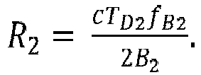
- the second estimated range is based on a second dominant frequency component of the second beat frequency signal and the step of determining the second estimated range comprises converting the second dominant frequency component, f B2 , of the second beat frequency signal to the second estimated range, R 2 , as a function of the speed of light, c, the second total sweep time, T D2 , wherein the second total sweep time is the period over which the second frequency varying detection signal is transmitted, and the second bandwidth B 2 as follows
- the method comprises the step of determining the first dominant frequency component of the first beat frequency signal by determining a Fourier transform of the first beat frequency signal and assigning values indicative of the amplitude of the Fourier transformed first beat frequency signal at a particular frequency to a first predetermined number of frequency-spaced bins, the frequency-spaced bins thereby each indicative of a different range of beat frequencies based on a resolution dependent on the first bandwidth of the first frequency varying detection signal;
- a computer program product comprising computer program code which, when executed by a processor, is configured to perform the method of the second aspect.
- an automotive radar system comprising the apparatus of the first aspect.
- Radar systems are becoming increasingly common in the automotive industry. These systems are used, for example, as sensors for assisted parking, automatic cruise control speed adjustment (adaptive cruise control), headway alert, collision warning and mitigation and brake support.
- automatic cruise control speed adjustment adaptive cruise control
- headway alert collision warning and mitigation and brake support.
- Radar (originally an acronym, RADAR) stands for RAdio Detection And Ranging. While radar technology was originally directed towards the use of radio frequency electromagnetic waves for detection and ranging, this term is now often used generically for electromagnetic waves of any frequency that are used for detection and ranging purposes.
- a radar system performs detection and ranging by transmitting an electromagnetic wave, such as a pulse, from a transmission antenna and measuring the time taken for the reflected wave to be detected at a receiving sensor. The amount of time taken for a reflected wave to reach an obstacle and be reflected back provides an indication of the range of that obstacle from the radar system.
- a series of pulses or a continuous wave mode of operation such as in a continuous wave radar
- a time-resolved range profile of a space around a radar system may be obtained. It will be appreciated that any action which includes the ranging of a remote object will inherently include the action of detecting said remote object.
- Figure 1 shows an apparatus 100 configured to provide for detection and ranging of a remote object 102, the apparatus configured to perform the following: based on a first reflected signal 106 comprising a reflection from the remote object 102 of a first frequency varying detection signal 105, the first frequency varying detection signal 105 comprising a signal that varies in frequency over a first bandwidth; and a second reflected signal 108 comprising a reflection from the remote object 102 of a second frequency varying detection signal 107, the second frequency varying detection signal 107 comprising a signal that varies in frequency over a second bandwidth, different from the first bandwidth; determine a first estimated range based on a first beat frequency signal 216 obtained by mixing the first reflected signal 206 and the first frequency varying detection signal 205, the first estimated range having a first resolution by virtue of the first bandwidth of the first frequency varying detection signal 205; determine a second estimated range based on a second beat frequency signal 217 obtained by mixing the second reflected signal 208 and the second frequency varying detection signal 207,
- the range of the remote object 102 may be determined based on a distance from a transmitter/receiver 103 that transmits the first and second frequency varying detection signals 105, 107 and receives the first and second reflected signals 106, 108, although it will be appreciated that with knowledge of the location of the transmitter/receiver 103, the range to the remote object 102 to any other known location can be determined.
- the transmitter/receiver 103 in this example comprises an automotive radar system, although it will be appreciated that in other examples the radar system may be used in fields other than automotive.
- the apparatus 100 may comprise at least one of (i) at least part of the automotive radar system 103, such as circuitry or a module of the same; (ii) a remote apparatus in communication with the automotive radar system 103 for control thereof and/or receipt of information therefrom; (iii) at least part of a user-interface-providing-device for an automobile, such as circuitry or a module of the same; and (iv) software or firmware for the automotive radar system 103.
- the apparatus 100 may be pre-installed in an automobile or it may be retro-fitted therein.
- the apparatus 100 may provide for communication with a user device 104, such as using a communication element 101, to provide the determined range to the device 104.
- Examples of devices 104 may comprise user devices which may include any device which may provide information to a user such as a dashboard indicator light, an on-board computer screen, a heads-up windscreen projection display or a mobile phone alert; or safety devices which may include automatic emergency braking, radar guided cruise control, road lane keeping assistance and autonomous driving.
- user devices which may include any device which may provide information to a user such as a dashboard indicator light, an on-board computer screen, a heads-up windscreen projection display or a mobile phone alert; or safety devices which may include automatic emergency braking, radar guided cruise control, road lane keeping assistance and autonomous driving.
- the apparatus 100 may be configured to provide signalling to cause the automotive radar system 103 to transmit one or more of the first frequency varying detection signal 105 and the second frequency varying detection signal 107.
- the automotive radar system 103 may be configured to transmit the frequency varying detection signals 105, 107 and the apparatus 100 may be configured only to determine the range of the remote object 102 based on the transmitted signals 105, 107 and the received, reflected signals 106, 108.
- the frequency varying detection signals 105, 107 are transmitted from, and the reflected signals 106, 108 are received by, an automotive radar system 103 incorporated into an automotive vehicle.
- the remote object 102 may be any object that comes within range of the automotive radar system 103, such as another automotive vehicle, a pedestrian or an obstacle.
- the automotive radar system 103 may be incorporated into another type of vehicle, such as a boat or an aeronautical vehicle. While an automotive radar system is referred to frequently in the described embodiments, it will be appreciated that the radar system described herein may be used in devices other than an automotive vehicle.
- Figure 2A shows an example of the variation of a transmission frequency (on the y -axis 202) of the first frequency varying detection signal 205 over time (on the x -axis 201). It can be seen from figure 2A that the frequency of the first frequency varying detection signal 205 varies in frequency over a fixed sweep time, T D , represented by the extent of line 205.
- the first frequency varying detection signal 205 varies from a predetermined starting frequency, f c , to a frequency equal to the starting frequency, f c , plus the first bandwidth, B 1 .
- the automotive radar system may be configured to begin a second sweep from f c to f c + B 1 . Repetitive sweeps may allow continuous ranging operations to be performed.
- Figure 2A shows the first reflected signal 206 as it is received at the automotive radar system 103.
- the first reflected signal 206 is generated when the first frequency varying detection signal 205 is reflected from the remote object 102 back to the automotive radar system 103.
- the first reflected signal 206 may be considered as a frequency varying reflected signal.
- An estimated range of the remote object 102 may be determined as a function of the time delay, t d , between sending the first frequency varying detection signal 205 and receiving the first reflected signal 206.
- the range to the remote object 102 may be determined from a beat frequency obtained by mixing the received first reflected signal 206 with the transmitted first frequency varying signal 205 and identifying a dominant or peak frequency component.
- the range may be determined from the frequency of that dominant or peak frequency component.
- Arrow 211 shows an example of the frequency offset between the first reflected signal 206 and the first frequency varying detection signal 205.
- Figure 2B shows the result of mixing the first reflected signal 206 with the first frequency varying detection signal 205.
- the result of this mixing is a beat frequency signal 208.
- Mixing may involve a step of performing a mathematical operation on the signals, such as multiplying the signals by one another.
- the mixing may include adding the signals to one another or subtracting one signal from the other. It will be appreciated that a range of methods of mixing signals may be considered by the skilled person and that certain mathematical operations may be equivalent to other mathematical operations by virtue of known equivalence identities, such as trigonometric identities.
- the beat frequency signal 216 if there is a remote object 102 present, comprises a dominant frequency component.
- the example beat frequency signal in figure 2B show a simple sinusoidal signal, though it will be appreciated that the beat frequency may be more complex than this signal, comprising a range of different frequency components. Where the beat frequency signal comprises a range of frequency components, one of the frequency components (comprising a signature of the remote object 102) may be the dominant frequency component of that signal.
- dotted lines 218 represent a time period over which one or more of: mixing the first frequency varying detection signal and the first reflected signal is performed; and sampling of the mixed signals is performed.
- the time period over which either of the above operations are performed begins at a short time period after the first portion of the first reflected signal is received and ends a short time period before the end of the first frequency varying detection signal output. It will be appreciated that performing either of the above operations over this time period may be particularly advantageous in a system which may be constrained by device limitations.
- either of the above two operations may be started as soon as the first reflected signal is received at the automotive radar system 103 and may be ended when the frequency of the first frequency varying detection signal reaches f c + B 1 .
- the apparatus may be configured to determine the beat frequency signal(s) based on the frequency varying detection signal and corresponding reflected signal temporally defined as a first threshold time after initial receipt of the reflected signal and/or a second threshold time prior to completion of the frequency sweep of the detection signal.
- Figure 2C shows a Fourier transform of the beat frequency signal 216 wherein the dominant frequency component is identified as peak 210.
- frequency is provided along the x -axis 203 and amplitude is shown along the y -axis 204.
- the dominant frequency component may be used to determine an estimated range of the remote object.
- the Fourier transform may comprise a Fast Fourier Transform (FFT) or another mathematical method in order to determine the dominant frequency component from the beat frequency signal 216. It will be appreciated that the Fourier transform of a more complex beat frequency signal 216 may produce a signal with multiple peaks at different frequency values along the x -axis of figure 2 .
- FFT Fast Fourier Transform
- the multiple peaks may comprise the signatures of different remote objects at different ranges or at least some of them may be due to noise.
- beat frequency signals where there is a single peak, e.g. comprising the signature of the remote object 102.
- the identification of a peak may be performed by any appropriate method, such as by identifying frequency components where the amplitude is above a predetermined threshold or by using a peak detection algorithm, which may be known to those skilled in the art.
- the dominant frequency component f B can then be used to determine the range, R, to the remote object 102.
- the resolution of the range is related to the bandwidth of the frequency varying detection signal used.
- One method for determining the range to a remote object 102 is to sample the Fourier transform of the beat frequency signal.
- the apparatus 100 may be configured to sample the Fourier transform of the beat frequency signal over predetermined time periods, ⁇ t.
- the method may comprise, metaphorically, placing the sampled values in a plurality of "bins" shown as circles 214.
- the act of performing/sampling the Fourier transform over time periods ⁇ t may inherently provide a range of possible bins of a resolution, in frequency space, which corresponds to the time period ⁇ t.
- the sampled value in each bin may represent the amplitude of the Fourier transform of the beat frequency signal at a specific beat frequency or over a specific range of beat frequencies.
- the frequency resolution of the bins may be independent of the bandwidth of the frequency dependent detection signal used.
- the x -axis of Figure 2C is a frequency axis.
- the identification of a peak or dominant frequency component by consideration of which bin contains the dominant sampled value may yield an estimate of the range to the remote object using equation 1 above, where f B comprises the beat frequency of the bin containing the dominant frequency component.
- f B comprises the beat frequency of the bin containing the dominant frequency component.
- the accuracy of the estimate is dependent at least on the bandwidth of the frequency varying detection signal.
- the sampling rate and therefore the number of bins used in the method may also affect the resolution of the estimated range because a low sample rate may not accurately identify at what beat frequency a peak is present. It will be appreciated that with a sufficiently high sampling rate, the bandwidth of the frequency varying detection signal may be the dominant factor in the resolution of the estimated range.
- Figures 3A - 3C show the case wherein two frequency varying detection signals 205, 207 are transmitted from an automotive radar system 103 with different bandwidths B 1 and B 2 , respectively.
- the first and second frequency varying detection signals 205, 207 are transmitted at the same time and therefore the first and second reflected signals 206, 208 corresponding to the reflections of the first and second frequency varying detection signals 205, 207 are received at the same time.
- the first frequency varying detection signal 205 and the second frequency varying detection 207 may be emitted at different times.
- time division multiplexing may be used.
- the first frequency varying detection signal 205 may be transmitted and the first reflected signal 206 received prior to the transmission of the second frequency varying detection signal 207 and subsequent receipt of its reflected signal 208.
- the reflected signals 206, 208 have different frequency offsets from the corresponding frequency varying detection signals 205, 207 which are being output at the time of receipt, as represented by arrows 211 and 212.
- the frequency offset 211, 212 may be related to the bandwidth and sweep time (the time over which the frequency of the frequency varying signals increase from starting frequency f c to frequency f c + B) and the range of the remote object.
- the first frequency varying detection signal 205 has a larger bandwidth B 1 than the second frequency varying detection 207 signal which has a bandwidth B 2 . It will be appreciated that in some embodiments B 2 may be larger than B 1 .
- Figure 3B shows the first 216 and second 217 beat frequency signals.
- the first beat frequency signal 216 is obtained by mixing the first frequency varying detection signal 205 and the first reflected signal 206 and the second beat frequency signal 217 is obtained by mixing the second frequency varying detection signal 207 and the second reflected signal 208. It will be appreciated that the two signals in figure 3B have been offset from one-another in order to provide clarity to the figure.
- Figure 3C shows the Fourier transforms of the first and second beat frequency signals.
- the first dominant frequency component 210 of the first beat frequency signal 216 corresponds to a first estimated range to the remote object 102 and the second dominant frequency component 213 of the second beat frequency signal 217 corresponds to a second estimated range to the remote object 102.
- the first and second estimated ranges may be calculated by way of equation (1), above. From equation (2), it can be seen that, even if the first dominant frequency component 210 and the second dominant frequency component 213 fall within the same bin (representing a common beat frequency as shown in Figure 3C ), the difference in the bandwidths, B 1 and B 2 , may result in different range measurements with different range resolutions because of the different bin size and position when converted into distance space. Thus, based on equations 1 and 2, each bin may represent a different range of distances to the remote object. It will be appreciated that the first and second estimated range may be combined in a number of ways in order to determine an estimated range of the remote object.
- a first distance or range can be determined from this value by understanding that the time delay t d must be twice the length of time light takes to travel to the remote object and back divided by the speed of light, c.
- An equivalent calculation can be performed using the second dominant frequency component 213 f B2 of the second beat frequency signal 217 and the second bandwidth B 2 to determine a second distance or range, R 2 .
- the range to the remote object may then be determined based on the first and second ranges, such as an average of the first and second ranges.
- the range to the remote object may be determined from the first and second frequency varying signals and their reflections based on the sampled Fourier transform methodology described above.
- the determination of the bin into which the dominant frequency component of the beat frequency signal falls may be performed by the apparatus.
- a separate element may determine into which bin the dominant frequency component of the beat frequency belongs and the apparatus may be configured to determine the range of the remote object 102 as a function of the first and second reflected signals and the first and second frequency varying detection signals.
- Figure 4 shows an example of an alternative way to visualise the bins described in relation to figure 3C .
- first and second rows of bins 400 and 401 are depicted which correspond to possible range estimates to the remote object calculated from the first and second reflected signals 206, 208 and the first and second frequency varying detection signals 205, 207.
- each bin instead of depicting the central points of the bins along the frequency axis (as in figures 2C and 3C which use circles 214 and 215), each bin has been represented as a box with an upper bound 402 and a lower bound 403 along an axis 408 that represents distance to the remote object.
- equations (2) and (4) have been applied to the bin frequencies of figure 3C in order to convert the frequency space bins 214 and 215 of figure 3C onto a distance axis 408.
- the different bandwidths of the first and second frequency varying detection signals result in different resolutions of the bins on the distance axis 408.
- Row 400 corresponds to the bins 214 of the first beat frequency signal 216 and row 401 corresponds to the bins 215 of the second beat frequency signal 217.
- the first dominant frequency component 210 of the first beat frequency signal 216 may be determined to lie within one of the bins of the first row 400.
- the second dominant frequency component 213 of the second beat frequency signal 217 may be determined to lie within one of the bins of the second row 401.
- the sampling rate of both the first frequency varying detection signal 205 and the second frequency varying detection signal 207 are the same.
- the sampling rate for each set of signals may be different, thereby providing a different number of bins associated with each of the first range estimate and the second range estimate.
- the n th bin of row 400 has a lower bound 402 and an upper bound 403.
- the difference between the lower and upper bound 402, 403 can be considered to be the range resolution of the sampled estimated range that the bin represents.
- the values between bounds 402 and 403 correspond to the estimated range which the bin represents.
- an equivalent set up is shown for the second row 401, wherein the lower bound of the n th bin is shown at 404 and the upper bound of the n th bin is shown at 405.
- Each bin is arranged adjacent its preceding and proceeding neighbours thus providing consecutive sampled distance ranges each with an associated resolution.
- the lower bound 402 of the n th bin corresponds to the upper bound of the (n-1) th bin
- the upper bound of the n th bin 403 corresponds to the lower bound of the (n+1) th bin.
- the total sweep time for the first frequency varying detection signal and the second frequency varying detection signal have been assumed to be the same. It will be appreciated that the sweep time for the two frequency varying detection signals may be different, thereby providing a sweep time T D1 corresponding to the sweep time of the first frequency varying detection signal and a sweep time T D2 corresponding to the sweep time of the second frequency varying detection signal.
- the maximum range the system can determine is a function of the total sweep time, T D .
- T D the total sweep time
- the number of bins is determined by the number of times the beat frequency is sampled over the total sweep time, T D .
- the total number of bins for the first range estimate, N may then be equal to the total time T D divided by the sampling time period ⁇ t.
- two possible dominant frequency components with equal magnitudes may be determined: a positive dominant frequency component and a negative dominant frequency component. The determination of both a positive and negative value is an inherent feature of performing a Fourier transform.
- the negative dominant frequency component may not be considered, as it may not have a practical significance.
- the resolution of the first range estimate, ⁇ R 1 , of each bin may, therefore, be equal to c /(2 B 1 ), where c is the speed of light and B 1 is the first bandwidth.
- the resolution for the second range estimate, ⁇ R 2 , of each bin may, therefore, be equal to c/(2B 2 ), wherein c is the speed of light and B 1 is the second bandwidth.
- the first dominant frequency component 210 of the first beat frequency signal 216 falls within the n th bin in row 400 and the second dominant frequency component 213 of the second beat frequency signal 217 also falls within the n th bin in row 401.
- this provides two different range estimates.
- the first dominant frequency component 210 may fall within the n th bin while the second dominant frequency component 213 may fall within a different bin, such as the (n+1) th bin.
- it can be surmised that a more accurate determination of the range must lie within the portions of the two bins which overlap, which may define a narrower range of beat frequencies than covered by the n th bins individually.
- the apparatus 100 may be configured to determine which of the first lower bound 402 of the n th bin of the first row 400 and the second lower bound 404 of the n th bin of the second row 401 has a higher frequency value and set that frequency value as a third lower bound 406.
- the apparatus 100 may further be configured to determine which of the first upper bound 403 of the n th bin of the first row 400 and the second upper bound 405 of the n th bin of the second row 401 has a lower frequency value and set that frequency value as a third upper bound 407.
- the third resolution may be defined as the difference between the third lower bound 406 and the third upper bound 407.
- the determined range to the remote object 102 may be determined to be the midpoint of the third lower bound 406 and the third upper bound 407. Thus, determining the range to the remote object 102 using the overlap in range estimate of the bins containing a peak amplitude results in a determined range which is narrower (has a higher resolution) than either of the first estimated range or the second estimated range.
- only one of a third upper bound 407 or a third lower bound 406 may be calculated and used in combination with the one of the lower bounds of the nth bins of the first and second rows or the upper bounds of one of the n th bins of the first and second rows 400, 401 respectively, in order to provide an improved range determination.
- one of the first lower bound 402 of the n th bin of the first row 400 may have the same frequency value as the second lower bound 404 of the n th bin of the second row 401 or the first upper bound 403 of the n th bin of the first row 400 may have the same frequency value as the second upper bound 405 of the n th bin of the second row 401.
- the apparatus 100 may be configured to determine a first estimated range of a remote object 102 as a function of only the first frequency varying detection signal 205 and the first reflected signal 206. From the determination of the first estimated range, a second frequency bandwidth may be selected for a second frequency varying detection signal 207 as a function of the first estimated range. The apparatus 100 may be configured to select the second bandwidth such that only one bound between adjacent bins of the second row of bins 401 intersects with the bin corresponding to the determined bin of the first row 400.
- the apparatus 100 may be configured to send signalling representative of the determined range, and optionally, the resolution of the determined range, to the device 104.
- signalling may be sent to cause a driver feedback element of a vehicle to provide feedback if the remote object is within a predetermined range.
- signalling may be sent to one or more warning, navigation, driver assistance or safety systems for use thereby.
- the determined range may be sent to an automatic braking safety system to cause automatic braking in the event a possible collision with the remote object is determined.
- Alternate warning, slowing or safety mechanisms may be provided.
- the warning, navigation, driver assistance or safety systems may be provided for other vehicles beside the example automobile recited above, such as buses, lorries, aeroplanes and boats.
- three frequency varying detection signals may be transmitted of different bandwidths by the automotive radar system 103, three corresponding reflected signals may be received, three dominant components of three beat frequency signals calculated and, therefrom, three estimated ranges of the remote object 102 may be determined.
- a range of the remote object 102 may be determined from the three estimated ranges.
- the lower bound of the determined range may comprise the highest of lower bounds of the bins of the three distance estimates.
- the upper bound of the determined range may comprise the lowest of the upper bounds of the bins of the three distance estimates.
- the determined range may comprise the half-way point between the lower bound of the determined range and the upper bound of the determined range.
- more than three distance estimates may be determined and the determined range may be a function of each of the distance estimates.
- the automotive radar system 103 may be configured to output frequency varying detection signals in the form of electromagnetic waves.
- the frequencies of the frequency varying detection signals may be within the microwave frequency range.
- the frequencies may be between 1 - 300 GHz.
- the frequencies may be between 20 - 200 GHz or between 30 - 100 GHz.
- the frequency of the microwaves may be approximately 77 GHz with a bandwidth of up to 1 GHz or the frequency of the microwaves may be approximately 79 GHz with a bandwidth of up to 4 GHz.
- the first and second bandwidths may be within these limits.
- these frequency ranges may be particularly advantageous for an automotive radar system 103 because these frequencies may lie within regulated frequency bands for automotive radar systems.
- other frequencies may be used where allowable by relevant national regulations.
- the wireless signals output by the automotive radar system 103 may comprise carrier waves for information intended for the remote device 102.
- Figure 5 shows a flow chart representing the steps of a method 500 of the present disclosure.
- the method comprises the step of determining a first estimated range 501 based on a first beat frequency signal obtained by mixing the first reflected signal and the first frequency varying detection signal, the first estimated range having a first resolution by virtue of the first bandwidth of the first frequency varying detection signal.
- the method comprises the step of determining a second estimated range 502 based on a second beat frequency signal obtained by mixing the second reflected signal and the second frequency varying detection signal, the second estimated range having a second resolution by virtue of the second bandwidth of the second frequency varying detection signal.
- the method further comprises the step of determining a range of the remote object 503 as a function of the first estimated range and the second estimated range.
- the set of instructions/method steps described above are implemented as functional and software instructions embodied as a set of executable instructions which are effected on a computer or machine which is programmed with and controlled by said executable instructions. Such instructions are loaded for execution on a processor (such as one or more CPUs) having memory associated therewith.
- a processor such as one or more CPUs
- the term processor includes microprocessors, microcontrollers, processor modules or subsystems (including one or more microprocessors or microcontrollers), or other control or computing devices.
- a processor can refer to a single component or to plural components.
- the set of instructions/methods illustrated herein and data and instructions associated therewith are stored in respective storage devices, which are implemented as one or more non-transient machine or computer-readable or computer-usable storage media or mediums.
- Such computer-readable or computer usable storage medium or media is (are) considered to be part of an article (or article of manufacture).
- An article or article of manufacture can refer to any manufactured single component or multiple components.
- the non-transient machine or computer usable media or mediums as defined herein excludes signals, but such media or mediums may be capable of receiving and processing information from signals and/or other transient mediums.
- Figure 6 shows an automobile 610 that may comprise a system 600 comprising the apparatus 100 and automotive radar system 103 described above.
- the automobile may comprise a car, a self-driving car, a truck, a lorry, a van, a caravan, a motorbike, a utility vehicle, a boat, a ship, a drone, an aircraft or an emergency services vehicle.
- a computer program configured to perform the method described above.
- the computer program is provided by a computer program product 700 comprising a computer readable medium bearing computer program code for execution by a processor associated memory, the computer program code comprising code for performing the method described above.
- the computer program may be executed by a processor of an automotive radar system 103 or a processor in communication with the automotive radar system 103.
- Example embodiments of the material discussed in this specification can be implemented in whole or in part through network, computer, or data based devices and/or services. These may include cloud, internet, intranet, mobile, desktop, processor, look-up table, microcontroller, consumer equipment, infrastructure, or other enabling devices and services. As may be used herein and in the claims, the following non-exclusive definitions are provided.
- one or more instructions or steps discussed herein are automated.
- the terms automated or automatically mean controlled operation of an apparatus, system, and/or process using computers and/or mechanical/electrical devices without the necessity of human intervention, observation, effort and/or decision.
- any components said to be coupled may be coupled or connected either directly or indirectly.
- additional components may be located between the two components that are said to be coupled.
Landscapes
- Engineering & Computer Science (AREA)
- Radar, Positioning & Navigation (AREA)
- Remote Sensing (AREA)
- Physics & Mathematics (AREA)
- Computer Networks & Wireless Communication (AREA)
- General Physics & Mathematics (AREA)
- Electromagnetism (AREA)
- Radar Systems Or Details Thereof (AREA)
Abstract
Description
- The present disclosure relates to an apparatus for detection and ranging of a remote object. It also relates to associated methods and computer programs.
- According to a first aspect of the present disclosure there is provided an apparatus configured to provide for detection and ranging of a remote object, the apparatus configured to perform the following:
- based on a first reflected signal comprising a reflection from the remote object of a first frequency varying detection signal, the first frequency varying detection signal comprising a signal that varies in frequency over a first bandwidth; and
- based on a second reflected signal comprising a reflection from the remote object of a second frequency varying detection signal, the second frequency varying detection signal comprising a signal that varies in frequency over a second bandwidth, different from the first bandwidth;
- determine a first estimated range based on a first beat frequency signal obtained by mixing the first reflected signal and the first frequency varying detection signal, the first estimated range having a first resolution by virtue of the first bandwidth of the first frequency varying detection signal;
- determine a second estimated range based on a second beat frequency signal obtained by mixing the second reflected signal and the second frequency varying detection signal, the second estimated range having a second resolution by virtue of the second bandwidth of the second frequency varying detection signal;
- determine a range of the remote object as a function of the first estimated range and the second estimated range.
- In one or more embodiments, determining a range to the remote object as a function of the first and second estimated ranges may provide for determination of a range having a higher resolution than the resolution of the component, first and second, estimates of range.
- In one or more embodiments the apparatus is configured to: determine a first spread of ranges based on the first estimated range and the resolution of the first estimated range according to the first bandwidth; determine of a second spread of ranges based on the second estimated range and the resolution of the second estimated range according to the second bandwidth; wherein the resolution, ΔR, is calculated as a function of the bandwidth, B, and the speed of light, c, using:

- In one or more embodiments the first estimated range is based on a first dominant frequency component of the first beat frequency signal and the second estimated range is based on a second dominant frequency component of the second beat frequency signal.
- In one or more embodiments the dominant frequency component may comprise the frequency component of the beat frequency signal having the highest corresponding amplitude.
- In one or more embodiments, the dominant frequency component may comprise the frequency component of the beat frequency signal having an amplitude above a threshold, the threshold comprising an absolute threshold or a threshold related to one or more amplitudes of the beat frequency signal.
- In one or more embodiments, the apparatus is configured to convert the first dominant frequency component, fB1, of the first beat frequency signal to the first estimated range, R1, as a function of the speed of light, c, the first total sweep time, TD1, wherein the first total sweep time is the period over which the first frequency varying detection signal is transmitted, and the first bandwidth, B1 as follows:

- In one or more embodiments the apparatus is configured to;
- determine the first dominant frequency component of the first beat frequency signal by determination of a Fourier transform of the first beat frequency signal and assigning values indicative of the amplitude of the Fourier transformed first beat frequency signal at a particular frequency to a first predetermined number of frequency-spaced bins, the frequency-spaced bins thereby each indicative of a different range of beat frequencies based on a resolution dependent on the first bandwidth of the first frequency varying detection signal;
- determine the second dominant frequency component of the second beat frequency signal by determination of a Fourier transform of the second beat frequency signal and assigning values indicative of the amplitude of the Fourier transformed first beat frequency signal at a particular frequency to a second predetermined number of frequency-spaced bins, the frequency-spaced bins thereby each indicative of a different range of beat frequencies based on a resolution dependent on the second bandwidth of the second frequency varying detection signal;
- determine which one of the bins of the first predetermined number of frequency-spaced bins contains the first dominant frequency component;
- convert the first dominant frequency component into the first estimated range;
- determine which one of the bins of the second predetermined number of frequency-spaced bins contains the second dominant frequency component;
- convert the second dominant frequency component into the second estimated range;
- based on an overlap in the range of distances covered by each of the identified bins the apparatus is configured to determine the range to the remote object having a resolution based on the overlap in range of beat frequencies.
- In one or more embodiments the second bandwidth of the second frequency varying detection signal is determined based on the determination of the first estimated range.
- In one or more embodiments the second bandwidth of the second frequency varying detection signal is determined based on the first bandwidth and the number of the nth bin, wherein the first dominant frequency component is found in the nth bin and bins are numbered consecutively from 1, as follows:

- In one or more embodiments the apparatus is configured to provide for transmission of the first frequency varying detection signal; determine a first estimated range to the remote object based on the first frequency varying detection signal and the first reflected signal; determine the second bandwidth to provide an improvement in resolution based on the determination of the first estimated range and provide for transmission of the second frequency varying detection signal with the determined second bandwidth; determine a second estimated range to the remote object based on the second frequency varying detection signal and the second reflected signal; and determine the range to the remote object based on the first estimated range and the second estimated range.
- According to a second aspect of the present disclosure there is provided a method for detection and ranging of a remote object:
- based on a first reflected signal comprising a reflection from the remote object of a first frequency varying detection signal, the first frequency varying detection signal comprising a signal that varies in frequency over a first bandwidth; and
- based on a second reflected signal comprising a reflection from the remote object of a second frequency varying detection signal, the second frequency varying detection signal comprising a signal that varies in frequency over a second bandwidth, different from the first bandwidth;
- determining a first estimated range based on a first beat frequency signal obtained by mixing the first reflected signal and the first frequency varying detection signal, the first estimated range having a first resolution by virtue of the first bandwidth of the first frequency varying detection signal;
- determining a second estimated range based on a second beat frequency signal obtained by mixing the second reflected signal and the second frequency varying detection signal, the second estimated range having a second resolution by virtue of the second bandwidth of the second frequency varying detection signal;
- determining a range of the remote object as a function of the first estimated range and the second estimated range.
- In one or more embodiments the method comprises determining a first spread of ranges based on the first estimated range and the resolution of the first estimated range according to the first bandwidth;
- determining a second spread of ranges based on the second estimated range and the resolution of the second estimated range according to the second bandwidth;
- wherein the resolution, ΔR, is calculated as a function of the bandwidth, B, and the speed of light, c, using:

- and wherein determining the range of the remote object comprises a function based on an overlap in the first and second spread of ranges.
- In one or more embodiments, the first estimated range is based on a first dominant frequency component of the first beat frequency signal and the step of determining the first estimated range comprises converting the first dominant frequency component, fB1, of the first beat frequency signal to the first estimated range, R1, as a function of the speed of light, c, the first total sweep time, TD1, wherein the first total sweep time is the period over which the first frequency varying detection signal is transmitted, and the first bandwidth, B1 as follows:


- In one or more embodiments the method comprises the step of determining the first dominant frequency component of the first beat frequency signal by determining a Fourier transform of the first beat frequency signal and assigning values indicative of the amplitude of the Fourier transformed first beat frequency signal at a particular frequency to a first predetermined number of frequency-spaced bins, the frequency-spaced bins thereby each indicative of a different range of beat frequencies based on a resolution dependent on the first bandwidth of the first frequency varying detection signal;
- determining the second dominant frequency component of the second beat frequency signal by determining a Fourier transform of the second beat frequency signal and assigning values indicative of the amplitude of the Fourier transformed first beat frequency signal at a particular frequency to a second predetermined number of frequency-spaced bins, the frequency-spaced bins thereby each indicative of a different range of beat frequencies based on a resolution dependent on the second bandwidth of the second frequency varying detection signal;
- determining which one of the bins of the first predetermined number of frequency-spaced bins contains the first dominant frequency component;
- converting the first dominant frequency component into the first estimated range;
- determining which one of the bins of the second predetermined number of frequency-spaced bins contains the second dominant frequency component;
- converting the second dominant frequency component into the second estimated range;
- based on an overlap in the range of distances covered by each of the identified bins, determining the range to the remote object having a resolution based on the overlap in range of beat frequencies.
- In one or more embodiments the method further comprises the step of determining the second bandwidth of the second frequency varying detection signal based on the first bandwidth and the number of the nth bin, wherein the first dominant frequency component is found in the nth bin and bins are numbered consecutively from 1, as follows:

- According to a third aspect of the present disclosure there is provided a computer program product comprising computer program code which, when executed by a processor, is configured to perform the method of the second aspect.
- According to a fourth aspect of the present disclosure there is provided an automotive radar system comprising the apparatus of the first aspect.
- While the disclosure is amenable to various modifications and alternative forms, specifics thereof have been shown by way of example in the drawings and will be described in detail. It should be understood, however, that other embodiments, beyond the particular embodiments described, are possible as well. All modifications, equivalents, and alternative embodiments falling within the spirit and scope of the appended claims are covered as well.
- The above discussion is not intended to represent every example embodiment or every implementation within the scope of the current or future Claim sets. The figures and Detailed Description that follow also exemplify various example embodiments. Various example embodiments may be more completely understood in consideration of the following Detailed Description in connection with the accompanying Drawings.
- One or more embodiments will now be described by way of example only with reference to the accompanying drawings in which:
-
Figure 1 shows a schematic diagram showing an example embodiment of an automotive radar system including the apparatus; -
Figures 2A - 2C show an example embodiment of how a frequency varying detection signal, a reflected signal and a beat frequency signal vary with time and how a dominant frequency component of the beat frequency signal may be visualised in frequency space; -
Figure 3A - 3C show an example embodiment of how first and second frequency varying detection signals, first and second reflected signals and first and second beat frequency signals vary with time and how first and second dominant frequency components of first and second beat frequency signals may be visualised in frequency space; -
Figure 4 shows an example embodiment of the calculation of a determined range with an improved resolution; -
Figure 5 shows an example method; -
Figure 6 shows an example automotive vehicle comprising an automotive radar system; and -
Figure 7 shows a computer readable medium. - Radar systems are becoming increasingly common in the automotive industry. These systems are used, for example, as sensors for assisted parking, automatic cruise control speed adjustment (adaptive cruise control), headway alert, collision warning and mitigation and brake support. We describe example embodiments that provide for an advantageous multi-use radar system which combines the functionalities mentioned above with a wireless signalling system for communication with a remote device.
- Radar (originally an acronym, RADAR) stands for RAdio Detection And Ranging. While radar technology was originally directed towards the use of radio frequency electromagnetic waves for detection and ranging, this term is now often used generically for electromagnetic waves of any frequency that are used for detection and ranging purposes.
- A radar system performs detection and ranging by transmitting an electromagnetic wave, such as a pulse, from a transmission antenna and measuring the time taken for the reflected wave to be detected at a receiving sensor. The amount of time taken for a reflected wave to reach an obstacle and be reflected back provides an indication of the range of that obstacle from the radar system. By using a series of pulses or a continuous wave mode of operation (such as in a continuous wave radar), a time-resolved range profile of a space around a radar system may be obtained. It will be appreciated that any action which includes the ranging of a remote object will inherently include the action of detecting said remote object.
-
Figure 1 shows anapparatus 100 configured to provide for detection and ranging of aremote object 102, the apparatus configured to perform the following: based on a first reflectedsignal 106 comprising a reflection from theremote object 102 of a first frequency varyingdetection signal 105, the first frequency varyingdetection signal 105 comprising a signal that varies in frequency over a first bandwidth; and a second reflectedsignal 108 comprising a reflection from theremote object 102 of a second frequency varyingdetection signal 107, the second frequency varyingdetection signal 107 comprising a signal that varies in frequency over a second bandwidth, different from the first bandwidth; determine a first estimated range based on a firstbeat frequency signal 216 obtained by mixing the first reflectedsignal 206 and the first frequency varyingdetection signal 205, the first estimated range having a first resolution by virtue of the first bandwidth of the first frequency varyingdetection signal 205; determine a second estimated range based on a secondbeat frequency signal 217 obtained by mixing the second reflectedsignal 208 and the second frequency varyingdetection signal 207, the second estimated range having a second resolution by virtue of the second bandwidth of the second frequency varyingdetection signal 207; determine a range of theremote object 102 as a function of the first estimated range and the second estimated range. - The range of the
remote object 102 may be determined based on a distance from a transmitter/receiver 103 that transmits the first and second frequency varying detection signals 105, 107 and receives the first and second reflected signals 106, 108, although it will be appreciated that with knowledge of the location of the transmitter/receiver 103, the range to theremote object 102 to any other known location can be determined. The transmitter/receiver 103 in this example comprises an automotive radar system, although it will be appreciated that in other examples the radar system may be used in fields other than automotive. - The
apparatus 100 may comprise at least one of (i) at least part of theautomotive radar system 103, such as circuitry or a module of the same; (ii) a remote apparatus in communication with theautomotive radar system 103 for control thereof and/or receipt of information therefrom; (iii) at least part of a user-interface-providing-device for an automobile, such as circuitry or a module of the same; and (iv) software or firmware for theautomotive radar system 103. Theapparatus 100 may be pre-installed in an automobile or it may be retro-fitted therein. Optionally, theapparatus 100 may provide for communication with auser device 104, such as using acommunication element 101, to provide the determined range to thedevice 104. - Examples of
devices 104 may comprise user devices which may include any device which may provide information to a user such as a dashboard indicator light, an on-board computer screen, a heads-up windscreen projection display or a mobile phone alert; or safety devices which may include automatic emergency braking, radar guided cruise control, road lane keeping assistance and autonomous driving. - The
apparatus 100 may be configured to provide signalling to cause theautomotive radar system 103 to transmit one or more of the first frequency varyingdetection signal 105 and the second frequency varyingdetection signal 107. Alternatively, theautomotive radar system 103 may be configured to transmit the frequency varying detection signals 105, 107 and theapparatus 100 may be configured only to determine the range of theremote object 102 based on the transmitted signals 105, 107 and the received, reflectedsignals - In one or more embodiments, the frequency varying detection signals 105, 107 are transmitted from, and the reflected signals 106, 108 are received by, an
automotive radar system 103 incorporated into an automotive vehicle. In this embodiment, theremote object 102 may be any object that comes within range of theautomotive radar system 103, such as another automotive vehicle, a pedestrian or an obstacle. In other embodiments, theautomotive radar system 103 may be incorporated into another type of vehicle, such as a boat or an aeronautical vehicle. While an automotive radar system is referred to frequently in the described embodiments, it will be appreciated that the radar system described herein may be used in devices other than an automotive vehicle. -
Figure 2A shows an example of the variation of a transmission frequency (on the y-axis 202) of the first frequency varyingdetection signal 205 over time (on the x-axis 201). It can be seen fromfigure 2A that the frequency of the first frequency varyingdetection signal 205 varies in frequency over a fixed sweep time, TD , represented by the extent ofline 205. The first frequency varyingdetection signal 205 varies from a predetermined starting frequency, fc, to a frequency equal to the starting frequency, fc, plus the first bandwidth, B1 . After the automotive radar system has transmitted a first sweep from fc to fc + B1 , the automotive radar system may be configured to begin a second sweep from fc to fc + B1 . Repetitive sweeps may allow continuous ranging operations to be performed. - Similarly,
Figure 2A shows the first reflectedsignal 206 as it is received at theautomotive radar system 103. The first reflectedsignal 206 is generated when the first frequency varyingdetection signal 205 is reflected from theremote object 102 back to theautomotive radar system 103. Thus, the first reflectedsignal 206 may be considered as a frequency varying reflected signal. - An estimated range of the
remote object 102 may be determined as a function of the time delay, td, between sending the first frequency varyingdetection signal 205 and receiving the first reflectedsignal 206. However, for a continuous wave radar system the range to theremote object 102 may be determined from a beat frequency obtained by mixing the received first reflectedsignal 206 with the transmitted firstfrequency varying signal 205 and identifying a dominant or peak frequency component. The range may be determined from the frequency of that dominant or peak frequency component.Arrow 211 shows an example of the frequency offset between the first reflectedsignal 206 and the first frequency varyingdetection signal 205. -
Figure 2B shows the result of mixing the first reflectedsignal 206 with the first frequency varyingdetection signal 205. The result of this mixing is abeat frequency signal 208. Mixing may involve a step of performing a mathematical operation on the signals, such as multiplying the signals by one another. In other example, the mixing may include adding the signals to one another or subtracting one signal from the other. It will be appreciated that a range of methods of mixing signals may be considered by the skilled person and that certain mathematical operations may be equivalent to other mathematical operations by virtue of known equivalence identities, such as trigonometric identities. Thebeat frequency signal 216, if there is aremote object 102 present, comprises a dominant frequency component. The example beat frequency signal infigure 2B show a simple sinusoidal signal, though it will be appreciated that the beat frequency may be more complex than this signal, comprising a range of different frequency components. Where the beat frequency signal comprises a range of frequency components, one of the frequency components (comprising a signature of the remote object 102) may be the dominant frequency component of that signal. - In
figure 2 , dottedlines 218 represent a time period over which one or more of: mixing the first frequency varying detection signal and the first reflected signal is performed; and sampling of the mixed signals is performed. Infigure 2 , the time period over which either of the above operations are performed begins at a short time period after the first portion of the first reflected signal is received and ends a short time period before the end of the first frequency varying detection signal output. It will be appreciated that performing either of the above operations over this time period may be particularly advantageous in a system which may be constrained by device limitations. In an embodiment wherein device limitations are negligible, either of the above two operations may be started as soon as the first reflected signal is received at theautomotive radar system 103 and may be ended when the frequency of the first frequency varying detection signal reaches fc + B1 . Thus, in one or more examples, the apparatus may be configured to determine the beat frequency signal(s) based on the frequency varying detection signal and corresponding reflected signal temporally defined as a first threshold time after initial receipt of the reflected signal and/or a second threshold time prior to completion of the frequency sweep of the detection signal. -
Figure 2C shows a Fourier transform of thebeat frequency signal 216 wherein the dominant frequency component is identified aspeak 210. Infigure 2C , frequency is provided along thex -axis 203 and amplitude is shown along the y-axis 204. The dominant frequency component may be used to determine an estimated range of the remote object. The Fourier transform may comprise a Fast Fourier Transform (FFT) or another mathematical method in order to determine the dominant frequency component from thebeat frequency signal 216. It will be appreciated that the Fourier transform of a more complexbeat frequency signal 216 may produce a signal with multiple peaks at different frequency values along the x-axis offigure 2 . The multiple peaks may comprise the signatures of different remote objects at different ranges or at least some of them may be due to noise. However, for simplicity, we will consider beat frequency signals where there is a single peak, e.g. comprising the signature of theremote object 102. The identification of a peak may be performed by any appropriate method, such as by identifying frequency components where the amplitude is above a predetermined threshold or by using a peak detection algorithm, which may be known to those skilled in the art. - The dominant frequency component fB can then be used to determine the range, R, to the
remote object 102. The following equation gives the range of an object;
- The resolution of the range is related to the bandwidth of the frequency varying detection signal used. The resolution ΔR is related to bandwidth as follows;

- One method for determining the range to a
remote object 102 is to sample the Fourier transform of the beat frequency signal. Accordingly, theapparatus 100 may be configured to sample the Fourier transform of the beat frequency signal over predetermined time periods, δt. The method may comprise, metaphorically, placing the sampled values in a plurality of "bins" shown as circles 214. The act of performing/sampling the Fourier transform over time periods δt may inherently provide a range of possible bins of a resolution, in frequency space, which corresponds to the time period δt. Thus, the sampled value in each bin may represent the amplitude of the Fourier transform of the beat frequency signal at a specific beat frequency or over a specific range of beat frequencies. In frequency space, the frequency resolution of the bins may be independent of the bandwidth of the frequency dependent detection signal used. The x-axis ofFigure 2C is a frequency axis. - The identification of a peak or dominant frequency component by consideration of which bin contains the dominant sampled value (e.g. highest amplitude of the Fourier transform) may yield an estimate of the range to the remote
object using equation 1 above, where fB comprises the beat frequency of the bin containing the dominant frequency component. However, the accuracy of the estimate is dependent at least on the bandwidth of the frequency varying detection signal. The sampling rate and therefore the number of bins used in the method may also affect the resolution of the estimated range because a low sample rate may not accurately identify at what beat frequency a peak is present. It will be appreciated that with a sufficiently high sampling rate, the bandwidth of the frequency varying detection signal may be the dominant factor in the resolution of the estimated range. -
Figures 3A - 3C show the case wherein two frequency varying detection signals 205, 207 are transmitted from anautomotive radar system 103 with different bandwidths B1 and B2, respectively. As can be seen inFigure 3A , the first and second frequency varying detection signals 205, 207 are transmitted at the same time and therefore the first and second reflected signals 206, 208 corresponding to the reflections of the first and second frequency varying detection signals 205, 207 are received at the same time. However, it will be appreciated that the first frequency varyingdetection signal 205 and the secondfrequency varying detection 207 may be emitted at different times. In one or more embodiments, time division multiplexing may be used. Further, it will be appreciated that the first frequency varyingdetection signal 205 may be transmitted and the first reflectedsignal 206 received prior to the transmission of the second frequency varyingdetection signal 207 and subsequent receipt of its reflectedsignal 208. The reflected signals 206, 208 have different frequency offsets from the corresponding frequency varying detection signals 205, 207 which are being output at the time of receipt, as represented byarrows - In the example of
figure 3A , the first frequency varyingdetection signal 205 has a larger bandwidth B1 than the secondfrequency varying detection 207 signal which has a bandwidth B2. It will be appreciated that in some embodiments B2 may be larger than B1. -
Figure 3B shows the first 216 and second 217 beat frequency signals. As described above, the firstbeat frequency signal 216 is obtained by mixing the first frequency varyingdetection signal 205 and the first reflectedsignal 206 and the secondbeat frequency signal 217 is obtained by mixing the second frequency varyingdetection signal 207 and the second reflectedsignal 208. It will be appreciated that the two signals infigure 3B have been offset from one-another in order to provide clarity to the figure. -
Figure 3C shows the Fourier transforms of the first and second beat frequency signals. - The first
dominant frequency component 210 of the firstbeat frequency signal 216 corresponds to a first estimated range to theremote object 102 and the seconddominant frequency component 213 of the secondbeat frequency signal 217 corresponds to a second estimated range to theremote object 102. The first and second estimated ranges may be calculated by way of equation (1), above. From equation (2), it can be seen that, even if the firstdominant frequency component 210 and the seconddominant frequency component 213 fall within the same bin (representing a common beat frequency as shown inFigure 3C ), the difference in the bandwidths, B1 and B2, may result in different range measurements with different range resolutions because of the different bin size and position when converted into distance space. Thus, based onequations - In one embodiment, the time delay, td, between the output of a first frequency varying
detection signal 205 and the receipt of the corresponding reflectedsignal 206 divided by the total time, TD , over which the sweep is performed can be calculated as a function of the first dominantfrequency component f B1 210 of the firstbeat frequency signal 216 and the bandwidth of the signal B1 as:
- A first distance or range can be determined from this value by understanding that the time delay td must be twice the length of time light takes to travel to the remote object and back divided by the speed of light, c. Thus, td in the above equation can be substituted and the equation rearranged to provide a first estimate of the range to the
remote object 102, R1 , as a function of the firstdominant frequency component 210 of the first beat frequency signal 216:
- An equivalent calculation can be performed using the second dominant frequency component 213 fB2 of the second
beat frequency signal 217 and the second bandwidth B2 to determine a second distance or range, R2. The range to the remote object may then be determined based on the first and second ranges, such as an average of the first and second ranges. - In another example, the range to the remote object may be determined from the first and second frequency varying signals and their reflections based on the sampled Fourier transform methodology described above.
- The determination of the bin into which the dominant frequency component of the beat frequency signal falls may be performed by the apparatus. Alternatively, a separate element may determine into which bin the dominant frequency component of the beat frequency belongs and the apparatus may be configured to determine the range of the
remote object 102 as a function of the first and second reflected signals and the first and second frequency varying detection signals. -
Figure 4 shows an example of an alternative way to visualise the bins described in relation tofigure 3C . Infigure 4 , first and second rows ofbins figures 2C and3C which usecircles 214 and 215), each bin has been represented as a box with an upper bound 402 and a lower bound 403 along anaxis 408 that represents distance to the remote object. Thus, in the representation offigure 4 , equations (2) and (4) have been applied to the bin frequencies offigure 3C in order to convert thefrequency space bins figure 3C onto adistance axis 408. The different bandwidths of the first and second frequency varying detection signals result in different resolutions of the bins on thedistance axis 408. Row 400 corresponds to thebins 214 of the firstbeat frequency signal 216 androw 401 corresponds to thebins 215 of the secondbeat frequency signal 217. Thus, upon performing a Fourier transform on the firstbeat frequency signal 216 and sampling the resulting signal into thebins 214, the firstdominant frequency component 210 of the firstbeat frequency signal 216 may be determined to lie within one of the bins of thefirst row 400. Equivalently, upon performing a Fourier transform on the secondbeat frequency signal 217 and sampling the resulting signal into the bin s215, the seconddominant frequency component 213 of the secondbeat frequency signal 217 may be determined to lie within one of the bins of thesecond row 401. In the present example, the sampling rate of both the first frequency varyingdetection signal 205 and the second frequency varyingdetection signal 207 are the same. In other embodiments, the sampling rate for each set of signals may be different, thereby providing a different number of bins associated with each of the first range estimate and the second range estimate. - As is the case for each bin, the nth bin of
row 400 has a lower bound 402 and an upper bound 403. The difference between the lower and upper bound 402, 403 can be considered to be the range resolution of the sampled estimated range that the bin represents. The values betweenbounds second row 401, wherein the lower bound of the nth bin is shown at 404 and the upper bound of the nth bin is shown at 405. Each bin is arranged adjacent its preceding and proceeding neighbours thus providing consecutive sampled distance ranges each with an associated resolution. Thus, the lower bound 402 of the nth bin corresponds to the upper bound of the (n-1)th bin and the upper bound of the nth bin 403 corresponds to the lower bound of the (n+1)th bin. - In the examples provided herein, the total sweep time for the first frequency varying detection signal and the second frequency varying detection signal have been assumed to be the same. It will be appreciated that the sweep time for the two frequency varying detection signals may be different, thereby providing a sweep time TD1 corresponding to the sweep time of the first frequency varying detection signal and a sweep time TD2 corresponding to the sweep time of the second frequency varying detection signal.
- The maximum range the system can determine is a function of the total sweep time, TD. The reason for this is that if a reflected
signal automotive radar system 103 after time TD from being emitted as a frequency varyingdetection signal - The number of bins is determined by the number of times the beat frequency is sampled over the total sweep time, TD. Sampling may be performed over a sampling time period, δt, which may be equal to the inverse of two times the starting frequency fc, i.e. δt = 1/(2fc). The total number of bins for the first range estimate, N, may then be equal to the total time TD divided by the sampling time period δt. After performing the Fourier transform on the beat frequency, two possible dominant frequency components with equal magnitudes may be determined: a positive dominant frequency component and a negative dominant frequency component. The determination of both a positive and negative value is an inherent feature of performing a Fourier transform. In this case the negative dominant frequency component may not be considered, as it may not have a practical significance. A result of performing a Fourier transform may be that the available bins, N, must be split around 0 to encompass both positive and negative values, thus only N/2 (= T/(2δt)) bins will actually be available. Due to the non-physical and non-practical consequences of the negative bin values and the negative range estimates, these have not been considered in detail throughout the above description.
- According to equation (2), the resolution of the first range estimate, ΔR1, of each bin may, therefore, be equal to c/(2B1 ), where c is the speed of light and B1 is the first bandwidth. Equivalently, the resolution for the second range estimate, ΔR2, of each bin may, therefore, be equal to c/(2B2), wherein c is the speed of light and B1 is the second bandwidth.
- As an example of one manner of determining range of a
remote object 102 as a function of thedominant frequency components - In this example the first
dominant frequency component 210 of the firstbeat frequency signal 216 falls within the nth bin inrow 400 and the seconddominant frequency component 213 of the secondbeat frequency signal 217 also falls within the nth bin inrow 401. As discussed previously, this provides two different range estimates. In another example, the firstdominant frequency component 210 may fall within the nth bin while the seconddominant frequency component 213 may fall within a different bin, such as the (n+1)th bin. In this example, it can be surmised that a more accurate determination of the range must lie within the portions of the two bins which overlap, which may define a narrower range of beat frequencies than covered by the nth bins individually. - In order to determine the range of the
remote object 102, theapparatus 100 may be configured to determine which of the first lower bound 402 of the nth bin of thefirst row 400 and the second lower bound 404 of the nth bin of thesecond row 401 has a higher frequency value and set that frequency value as a third lower bound 406. Theapparatus 100 may further be configured to determine which of the first upper bound 403 of the nth bin of thefirst row 400 and the second upper bound 405 of the nth bin of thesecond row 401 has a lower frequency value and set that frequency value as a third upper bound 407. The third resolution may be defined as the difference between the third lower bound 406 and the third upper bound 407. The determined range to theremote object 102 may be determined to be the midpoint of the third lower bound 406 and the third upper bound 407. Thus, determining the range to theremote object 102 using the overlap in range estimate of the bins containing a peak amplitude results in a determined range which is narrower (has a higher resolution) than either of the first estimated range or the second estimated range. - Alternatively, in one or more examples, only one of a third upper bound 407 or a third lower bound 406 may be calculated and used in combination with the one of the lower bounds of the nth bins of the first and second rows or the upper bounds of one of the nth bins of the first and
second rows first row 400 may have the same frequency value as the second lower bound 404 of the nth bin of thesecond row 401 or the first upper bound 403 of the nth bin of thefirst row 400 may have the same frequency value as the second upper bound 405 of the nth bin of thesecond row 401. - In one or more embodiments, the
apparatus 100 may be configured to determine a first estimated range of aremote object 102 as a function of only the first frequency varyingdetection signal 205 and the first reflectedsignal 206. From the determination of the first estimated range, a second frequency bandwidth may be selected for a second frequency varyingdetection signal 207 as a function of the first estimated range. Theapparatus 100 may be configured to select the second bandwidth such that only one bound between adjacent bins of the second row ofbins 401 intersects with the bin corresponding to the determined bin of thefirst row 400. For example, the selection of the second bandwidth B2 based on the first bandwidth B1 may be based on the following equation, wherein (n-1) is the number of the (n-1)th bin:
- The
apparatus 100 may be configured to send signalling representative of the determined range, and optionally, the resolution of the determined range, to thedevice 104. For example, signalling may be sent to cause a driver feedback element of a vehicle to provide feedback if the remote object is within a predetermined range. Alternatively, signalling may be sent to one or more warning, navigation, driver assistance or safety systems for use thereby. For example, the determined range may be sent to an automatic braking safety system to cause automatic braking in the event a possible collision with the remote object is determined. Alternate warning, slowing or safety mechanisms may be provided. The warning, navigation, driver assistance or safety systems may be provided for other vehicles beside the example automobile recited above, such as buses, lorries, aeroplanes and boats. - In the embodiments presented in the figures, two frequency varying detection signals are used in order to provide an improved range. In one or more embodiments, three frequency varying detection signals may be transmitted of different bandwidths by the
automotive radar system 103, three corresponding reflected signals may be received, three dominant components of three beat frequency signals calculated and, therefrom, three estimated ranges of theremote object 102 may be determined. A range of theremote object 102 may be determined from the three estimated ranges. For example, the lower bound of the determined range may comprise the highest of lower bounds of the bins of the three distance estimates. The upper bound of the determined range may comprise the lowest of the upper bounds of the bins of the three distance estimates. The determined range may comprise the half-way point between the lower bound of the determined range and the upper bound of the determined range. In another embodiment, more than three distance estimates may be determined and the determined range may be a function of each of the distance estimates. - The
automotive radar system 103 may be configured to output frequency varying detection signals in the form of electromagnetic waves. The frequencies of the frequency varying detection signals may be within the microwave frequency range. For example, the frequencies may be between 1 - 300 GHz. In particular, the frequencies may be between 20 - 200 GHz or between 30 - 100 GHz. As a specific example, the frequency of the microwaves may be approximately 77 GHz with a bandwidth of up to 1 GHz or the frequency of the microwaves may be approximately 79 GHz with a bandwidth of up to 4 GHz. Accordingly, the first and second bandwidths may be within these limits. In some example embodiments, these frequency ranges may be particularly advantageous for anautomotive radar system 103 because these frequencies may lie within regulated frequency bands for automotive radar systems. Alternatively, other frequencies may be used where allowable by relevant national regulations. Accordingly, the wireless signals output by theautomotive radar system 103 may comprise carrier waves for information intended for theremote device 102. -
Figure 5 shows a flow chart representing the steps of amethod 500 of the present disclosure. Based on a first reflected signal comprising a reflection from a remote object of a first frequency varying detection signal, the method comprises the step of determining a first estimatedrange 501 based on a first beat frequency signal obtained by mixing the first reflected signal and the first frequency varying detection signal, the first estimated range having a first resolution by virtue of the first bandwidth of the first frequency varying detection signal. Further, based on a second reflected signal comprising a reflection from the remote object of a second frequency varying detection signal, the second frequency varying detection signal comprising a signal that varies in frequency over a second bandwidth, different from the first bandwidth, the method comprises the step of determining a second estimatedrange 502 based on a second beat frequency signal obtained by mixing the second reflected signal and the second frequency varying detection signal, the second estimated range having a second resolution by virtue of the second bandwidth of the second frequency varying detection signal. The method further comprises the step of determining a range of theremote object 503 as a function of the first estimated range and the second estimated range. - The instructions and/or flowchart steps in the above figures can be executed in any order, unless a specific order is explicitly stated. Also, those skilled in the art will recognize that while one example set of instructions/method has been discussed, the material in this specification can be combined in a variety of ways to yield other examples as well, and are to be understood within a context provided by this detailed description.
- In some example embodiments the set of instructions/method steps described above are implemented as functional and software instructions embodied as a set of executable instructions which are effected on a computer or machine which is programmed with and controlled by said executable instructions. Such instructions are loaded for execution on a processor (such as one or more CPUs) having memory associated therewith. The term processor includes microprocessors, microcontrollers, processor modules or subsystems (including one or more microprocessors or microcontrollers), or other control or computing devices. A processor can refer to a single component or to plural components.
- In other examples, the set of instructions/methods illustrated herein and data and instructions associated therewith are stored in respective storage devices, which are implemented as one or more non-transient machine or computer-readable or computer-usable storage media or mediums. Such computer-readable or computer usable storage medium or media is (are) considered to be part of an article (or article of manufacture). An article or article of manufacture can refer to any manufactured single component or multiple components. The non-transient machine or computer usable media or mediums as defined herein excludes signals, but such media or mediums may be capable of receiving and processing information from signals and/or other transient mediums.
-
Figure 6 shows anautomobile 610 that may comprise asystem 600 comprising theapparatus 100 andautomotive radar system 103 described above. The automobile may comprise a car, a self-driving car, a truck, a lorry, a van, a caravan, a motorbike, a utility vehicle, a boat, a ship, a drone, an aircraft or an emergency services vehicle. - In another aspect of the present disclosure, there is a computer program configured to perform the method described above. In an example the computer program is provided by a
computer program product 700 comprising a computer readable medium bearing computer program code for execution by a processor associated memory, the computer program code comprising code for performing the method described above. The computer program may be executed by a processor of anautomotive radar system 103 or a processor in communication with theautomotive radar system 103. - Example embodiments of the material discussed in this specification can be implemented in whole or in part through network, computer, or data based devices and/or services. These may include cloud, internet, intranet, mobile, desktop, processor, look-up table, microcontroller, consumer equipment, infrastructure, or other enabling devices and services. As may be used herein and in the claims, the following non-exclusive definitions are provided.
- In one example, one or more instructions or steps discussed herein are automated. The terms automated or automatically (and like variations thereof) mean controlled operation of an apparatus, system, and/or process using computers and/or mechanical/electrical devices without the necessity of human intervention, observation, effort and/or decision.
- It will be appreciated that any components said to be coupled may be coupled or connected either directly or indirectly. In the case of indirect coupling, additional components may be located between the two components that are said to be coupled.
- In this specification, example embodiments have been presented in terms of a selected set of details. However, a person of ordinary skill in the art would understand that many other example embodiments may be practiced which include a different selected set of these details. It is intended that the following claims cover all possible example embodiments.
Claims (15)
- An apparatus configured to provide for detection and ranging of a remote object, the apparatus configured to perform the following:based on a first reflected signal comprising a reflection from the remote object of a first frequency varying detection signal, the first frequency varying detection signal comprising a signal that varies in frequency over a first bandwidth; andbased on a second reflected signal comprising a reflection from the remote object of a second frequency varying detection signal, the second frequency varying detection signal comprising a signal that varies in frequency over a second bandwidth, different from the first bandwidth;determine a first estimated range based on a first beat frequency signal obtained by mixing the first reflected signal and the first frequency varying detection signal, the first estimated range having a first resolution by virtue of the first bandwidth of the first frequency varying detection signal;determine a second estimated range based on a second beat frequency signal obtained by mixing the second reflected signal and the second frequency varying detection signal, the second estimated range having a second resolution by virtue of the second bandwidth of the second frequency varying detection signal;determine a range of the remote object as a function of the first estimated range and the second estimated range.
- The apparatus of claim 1, wherein the apparatus is configured to:determine a first spread of ranges based on the first estimated range and the resolution of the first estimated range according to the first bandwidth;determine of a second spread of ranges based on the second estimated range and the resolution of the second estimated range according to the second bandwidth;wherein the resolution, ΔR, is calculated as a function of the bandwidth, B, and the speed of light, c, using:
 and wherein the range of the remote object comprises a function based on an overlap in the first and second spread of ranges.
 - The apparatus of claim 1 or claim 2, wherein the first estimated range is based on a first dominant frequency component of the first beat frequency signal and the second estimated range is based on a second dominant frequency component of the second beat frequency signal.
- The apparatus of claim 3, wherein the apparatus is configured to convert the first dominant frequency component, fB1, of the first beat frequency signal to the first estimated range, R1, as a function of the speed of light, c, the first total sweep time, TD1, wherein the first total sweep time is the period over which the first frequency varying detection signal is transmitted, and the first bandwidth, B1 as follows:


- The apparatus of claim 4, wherein the apparatus is configured to;
determine the first dominant frequency component of the first beat frequency signal by determination of a Fourier transform of the first beat frequency signal and assigning values indicative of the amplitude of the Fourier transformed first beat frequency signal at a particular frequency to a first predetermined number of frequency-spaced bins, the frequency-spaced bins thereby each indicative of a different range of beat frequencies based on a resolution dependent on the first bandwidth of the first frequency varying detection signal;
determine the second dominant frequency component of the second beat frequency signal by determination of a Fourier transform of the second beat frequency signal and assigning values indicative of the amplitude of the Fourier transformed first beat frequency signal at a particular frequency to a second predetermined number of frequency-spaced bins, the frequency-spaced bins thereby each indicative of a different range of beat frequencies based on a resolution dependent on the second bandwidth of the second frequency varying detection signal;
determine which one of the bins of the first predetermined number of frequency-spaced bins contains the first dominant frequency component;
convert the first dominant frequency component into the first estimated range;
determine which one of the bins of the second predetermined number of frequency-spaced bins contains the second dominant frequency component;
convert the second dominant frequency component into the second estimated range;
based on an overlap in the range of distances covered by each of the identified bins the apparatus is configured to determine the range to the remote object having a resolution based on the overlap in range of beat frequencies. - The apparatus of any preceding claim, wherein the second bandwidth of the second frequency varying detection signal is determined based on the determination of the first estimated range.
- The apparatus of claim 6 when claim 6 is dependent on claim 5, wherein the second bandwidth of the second frequency varying detection signal is determined based on the first bandwidth and the number of the nth bin, wherein the first dominant frequency component is found in the nth bin and bins are numbered consecutively from 1, as follows:

- The apparatus of any preceding claim wherein the apparatus is configured to provide for transmission of the first frequency varying detection signal; determine a first estimated range to the remote object based on the first frequency varying detection signal and the first reflected signal; determine the second bandwidth to provide an improvement in resolution based on the determination of the first estimated range and provide for transmission of the second frequency varying detection signal with the determined second bandwidth; determine a second estimated range to the remote object based on the second frequency varying detection signal and the second reflected signal; and determine the range to the remote object based on the first estimated range and the second estimated range.
- A method for detection and ranging of a remote object:based on a first reflected signal comprising a reflection from the remote object of a first frequency varying detection signal, the first frequency varying detection signal comprising a signal that varies in frequency over a first bandwidth; andbased on a second reflected signal comprising a reflection from the remote object of a second frequency varying detection signal, the second frequency varying detection signal comprising a signal that varies in frequency over a second bandwidth, different from the first bandwidth;determining a first estimated range based on a first beat frequency signal obtained by mixing the first reflected signal and the first frequency varying detection signal, the first estimated range having a first resolution by virtue of the first bandwidth of the first frequency varying detection signal;determining a second estimated range based on a second beat frequency signal obtained by mixing the second reflected signal and the second frequency varying detection signal, the second estimated range having a second resolution by virtue of the second bandwidth of the second frequency varying detection signal;determining a range of the remote object as a function of the first estimated range and the second estimated range.
- The method of claim 9 comprising:determining a first spread of ranges based on the first estimated range and the resolution of the first estimated range according to the first bandwidth;determining a second spread of ranges based on the second estimated range and the resolution of the second estimated range according to the second bandwidth;wherein the resolution, ΔR, is calculated as a function of the bandwidth, B, and the speed of light, c, using:
 and wherein determining the range of the remote object comprises a function based on an overlap in the first and second spread of ranges.
 - The method of claim 9 or claim 10 wherein the first estimated range is based on a first dominant frequency component of the first beat frequency signal and the step of determining the first estimated range comprises converting the first dominant frequency component, fB1, of the first beat frequency signal to the first estimated range, R1, as a function of the speed of light, c, the first total sweep time, TD1, wherein the first total sweep time is the period over which the first frequency varying detection signal is transmitted, and the first bandwidth, B1 as follows:


- The method of claim 11 including the steps of:determining the first dominant frequency component of the first beat frequency signal by determining a Fourier transform of the first beat frequency signal and assigning values indicative of the amplitude of the Fourier transformed first beat frequency signal at a particular frequency to a first predetermined number of frequency-spaced bins, the frequency-spaced bins thereby each indicative of a different range of beat frequencies based on a resolution dependent on the first bandwidth of the first frequency varying detection signal;determining the second dominant frequency component of the second beat frequency signal by determining a Fourier transform of the second beat frequency signal and assigning values indicative of the amplitude of the Fourier transformed first beat frequency signal at a particular frequency to a second predetermined number of frequency-spaced bins, the frequency-spaced bins thereby each indicative of a different range of beat frequencies based on a resolution dependent on the second bandwidth of the second frequency varying detection signal;determining which one of the bins of the first predetermined number of frequency-spaced bins contains the first dominant frequency component;converting the first dominant frequency component into the first estimated range;determining which one of the bins of the second predetermined number of frequency-spaced bins contains the second dominant frequency component;converting the second dominant frequency component into the second estimated range;based on an overlap in the range of distances covered by each of the identified bins, determining the range to the remote object having a resolution based on the overlap in range of beat frequencies.
- The method of claim 12 wherein the method further comprises the step of determining the second bandwidth of the second frequency varying detection signal based on the first bandwidth and the number of the nth bin, wherein the first dominant frequency component is found in the nth bin and bins are numbered consecutively from 1, as follows:

- A computer program product comprising computer program code which, when executed by a processor, is configured to perform the method of any one of claims 9 - 13.
- An automotive radar system comprising the apparatus of any one of claims 1 - 8.
Priority Applications (3)
| Application Number | Priority Date | Filing Date | Title |
|---|---|---|---|
| EP17159347.8A EP3373034B1 (en) | 2017-03-06 | 2017-03-06 | Apparatus for detection and ranging |
| US15/908,958 US10746861B2 (en) | 2017-03-06 | 2018-03-01 | Apparatus for detection and ranging |
| CN201810183923.3A CN108535728B (en) | 2017-03-06 | 2018-03-06 | Device for detecting and ranging |
Applications Claiming Priority (1)
| Application Number | Priority Date | Filing Date | Title |
|---|---|---|---|
| EP17159347.8A EP3373034B1 (en) | 2017-03-06 | 2017-03-06 | Apparatus for detection and ranging |
Publications (2)
| Publication Number | Publication Date |
|---|---|
| EP3373034A1 true EP3373034A1 (en) | 2018-09-12 |
| EP3373034B1 EP3373034B1 (en) | 2020-02-26 |
Family
ID=58231509
Family Applications (1)
| Application Number | Title | Priority Date | Filing Date |
|---|---|---|---|
| EP17159347.8A Active EP3373034B1 (en) | 2017-03-06 | 2017-03-06 | Apparatus for detection and ranging |
Country Status (3)
| Country | Link |
|---|---|
| US (1) | US10746861B2 (en) |
| EP (1) | EP3373034B1 (en) |
| CN (1) | CN108535728B (en) |
Families Citing this family (6)
| Publication number | Priority date | Publication date | Assignee | Title |
|---|---|---|---|---|
| CN110927684B (en) * | 2018-09-20 | 2022-03-08 | 北京行易道科技有限公司 | A method and device for detecting the occlusion state of automotive radar |
| US10884100B2 (en) * | 2018-11-29 | 2021-01-05 | Toyota Jidosha Kabushiki Kaisha | Multi-carrier modulation on FMCW radar for integrated automotive radar and communication systems |
| CA3124910A1 (en) * | 2019-01-18 | 2020-07-23 | Flow-Tronic S.A. | Non-invasive open channel flow meter |
| KR102937939B1 (en) | 2020-09-15 | 2026-03-11 | 삼성전자주식회사 | Electronic apparatus and control method thereof |
| US12248089B2 (en) * | 2022-02-02 | 2025-03-11 | Qualcomm Incorporated | Frequency modulated continuous wave radar detection in the presence of phase noise |
| DE102024208193A1 (en) * | 2024-08-28 | 2026-03-05 | Robert Bosch Gesellschaft mit beschränkter Haftung | Radar sensor with digitally modulated transmission signal |
Citations (4)
| Publication number | Priority date | Publication date | Assignee | Title |
|---|---|---|---|---|
| US20100033364A1 (en) * | 2008-08-05 | 2010-02-11 | Fujitsu Ten Limited | Signal processing device, radar device, vehicle control device, and signal processing method |
| US20120229323A1 (en) * | 2011-03-09 | 2012-09-13 | Denso Corporation | Radar system and power-supply device incorporated in the same |
| US20150355321A1 (en) * | 2012-12-17 | 2015-12-10 | Denso Corporation | Fmcw radar apparatus |
| US20160139257A1 (en) * | 2014-11-19 | 2016-05-19 | Mitsubishi Electric Corporation | Fmcw radar device and fmcw radar signal processing method |
Family Cites Families (10)
| Publication number | Priority date | Publication date | Assignee | Title |
|---|---|---|---|---|
| GB620568A (en) * | 1945-07-25 | 1949-03-28 | Noel Meyer Rust | Improvements in radio location and detection arrangements |
| US5914683A (en) | 1996-09-12 | 1999-06-22 | O'conner; Joe S. | Ultra high resolution ranging unit |
| EP2278287B1 (en) * | 2003-10-27 | 2016-09-07 | The General Hospital Corporation | Method and apparatus for performing optical imaging using frequency-domain interferometry |
| CA2718699C (en) * | 2008-03-18 | 2018-11-13 | Manchester Metropolitan University | Remote detection and measurement of objects |
| US7791528B2 (en) * | 2008-11-24 | 2010-09-07 | Autoliv Asp, Inc. | Method and apparatus for radar signal processing |
| IT1392524B1 (en) * | 2008-12-31 | 2012-03-09 | Ids Ingegneria Dei Sistemi S P A | METHOD FOR INTERFEROMETRIC RADAR MEASUREMENTS |
| WO2011075639A1 (en) * | 2009-12-18 | 2011-06-23 | Christopher Gary Sentelle | Moving entity detection |
| US9279723B2 (en) * | 2010-08-19 | 2016-03-08 | Novatrans Group Sa | Terahertz spectroscopy system and method |
| DE102015120733B4 (en) * | 2015-11-30 | 2017-11-02 | Infineon Technologies Ag | Radar device with phase noise estimation |
| US9753121B1 (en) * | 2016-06-20 | 2017-09-05 | Uhnder, Inc. | Power control for improved near-far performance of radar systems |
-
2017
- 2017-03-06 EP EP17159347.8A patent/EP3373034B1/en active Active
-
2018
- 2018-03-01 US US15/908,958 patent/US10746861B2/en active Active
- 2018-03-06 CN CN201810183923.3A patent/CN108535728B/en active Active
Patent Citations (4)
| Publication number | Priority date | Publication date | Assignee | Title |
|---|---|---|---|---|
| US20100033364A1 (en) * | 2008-08-05 | 2010-02-11 | Fujitsu Ten Limited | Signal processing device, radar device, vehicle control device, and signal processing method |
| US20120229323A1 (en) * | 2011-03-09 | 2012-09-13 | Denso Corporation | Radar system and power-supply device incorporated in the same |
| US20150355321A1 (en) * | 2012-12-17 | 2015-12-10 | Denso Corporation | Fmcw radar apparatus |
| US20160139257A1 (en) * | 2014-11-19 | 2016-05-19 | Mitsubishi Electric Corporation | Fmcw radar device and fmcw radar signal processing method |
Also Published As
| Publication number | Publication date |
|---|---|
| EP3373034B1 (en) | 2020-02-26 |
| CN108535728A (en) | 2018-09-14 |
| US10746861B2 (en) | 2020-08-18 |
| US20180252802A1 (en) | 2018-09-06 |
| CN108535728B (en) | 2023-09-29 |
Similar Documents
| Publication | Publication Date | Title |
|---|---|---|
| US10746861B2 (en) | Apparatus for detection and ranging | |
| KR102445130B1 (en) | Method and apparatus for determining the lateral relative velocity component of a radar target | |
| US10267897B2 (en) | FMCW radar blocking detection | |
| US10473760B2 (en) | Radar device and vertical axis-misalignment detecting method | |
| KR20190096291A (en) | Rader sensing with phase correction | |
| CN108226918B (en) | Solution method for Doppler ambiguity under high signal-to-noise ratio | |
| US20150276929A1 (en) | Signal Processing Method and Device for Frequency-Modulated Continuous Waveform Radar System | |
| CN110579763A (en) | Resolving Doppler ambiguity in a multiple-input multiple-output radar using digital multiple-pulse repetition frequency | |
| KR20150051679A (en) | Vechicle radar for discriminating false target using variable wave and method for discriminating false target using it | |
| CN108152809B (en) | Direct doppler-free velocity measurement in chirp radar | |
| CN103245946A (en) | Vechicle-mounted radar apparatus | |
| JP7173735B2 (en) | Radar device and signal processing method | |
| EP3451015B1 (en) | Method and apparatus for detecting object using radar of vehicle | |
| CN111630406B (en) | Method for determining object information items and radar system, vehicle driver assistance system | |
| CN104977566B (en) | Signal processing method and device for a frequency modulation continuous wave radar sensing system | |
| US10823833B2 (en) | Apparatus for detection and ranging | |
| CN113325421B (en) | Method and computer readable medium for providing the at least one target information | |
| EP4312058A1 (en) | Velocity disambiguation for radar sensor system | |
| US20240125924A1 (en) | Radar system and corresponding method | |
| KR101652688B1 (en) | Radar apparatus and multiple sampling method thereof | |
| EP4273580A1 (en) | Signal modeling for unambiguous range rate estimation | |
| EP4538734A1 (en) | Transmit power control for automotive radar sensing | |
| JP7247413B2 (en) | ELECTRONIC DEVICE, ELECTRONIC DEVICE CONTROL METHOD, AND PROGRAM | |
| EP4506725A1 (en) | Fmcw radar with dynamic waveform model based on ego motion | |
| CN116888498A (en) | Radar systems and corresponding methods |
Legal Events
| Date | Code | Title | Description |
|---|---|---|---|
| PUAI | Public reference made under article 153(3) epc to a published international application that has entered the european phase |
Free format text: ORIGINAL CODE: 0009012 |
|
| STAA | Information on the status of an ep patent application or granted ep patent |
Free format text: STATUS: THE APPLICATION HAS BEEN PUBLISHED |
|
| AK | Designated contracting states |
Kind code of ref document: A1 Designated state(s): AL AT BE BG CH CY CZ DE DK EE ES FI FR GB GR HR HU IE IS IT LI LT LU LV MC MK MT NL NO PL PT RO RS SE SI SK SM TR |
|
| AX | Request for extension of the european patent |
Extension state: BA ME |
|
| STAA | Information on the status of an ep patent application or granted ep patent |
Free format text: STATUS: REQUEST FOR EXAMINATION WAS MADE |
|
| 17P | Request for examination filed |
Effective date: 20190312 |
|
| RBV | Designated contracting states (corrected) |
Designated state(s): AL AT BE BG CH CY CZ DE DK EE ES FI FR GB GR HR HU IE IS IT LI LT LU LV MC MK MT NL NO PL PT RO RS SE SI SK SM TR |
|
| GRAP | Despatch of communication of intention to grant a patent |
Free format text: ORIGINAL CODE: EPIDOSNIGR1 |
|
| STAA | Information on the status of an ep patent application or granted ep patent |
Free format text: STATUS: GRANT OF PATENT IS INTENDED |
|
| INTG | Intention to grant announced |
Effective date: 20190819 |
|
| GRAJ | Information related to disapproval of communication of intention to grant by the applicant or resumption of examination proceedings by the epo deleted |
Free format text: ORIGINAL CODE: EPIDOSDIGR1 |
|
| STAA | Information on the status of an ep patent application or granted ep patent |
Free format text: STATUS: REQUEST FOR EXAMINATION WAS MADE |
|
| GRAP | Despatch of communication of intention to grant a patent |
Free format text: ORIGINAL CODE: EPIDOSNIGR1 |
|
| STAA | Information on the status of an ep patent application or granted ep patent |
Free format text: STATUS: GRANT OF PATENT IS INTENDED |
|
| GRAS | Grant fee paid |
Free format text: ORIGINAL CODE: EPIDOSNIGR3 |
|
| INTG | Intention to grant announced |
Effective date: 20200109 |
|
| GRAA | (expected) grant |
Free format text: ORIGINAL CODE: 0009210 |
|
| STAA | Information on the status of an ep patent application or granted ep patent |
Free format text: STATUS: THE PATENT HAS BEEN GRANTED |
|
| AK | Designated contracting states |
Kind code of ref document: B1 Designated state(s): AL AT BE BG CH CY CZ DE DK EE ES FI FR GB GR HR HU IE IS IT LI LT LU LV MC MK MT NL NO PL PT RO RS SE SI SK SM TR |
|
| REG | Reference to a national code |
Ref country code: GB Ref legal event code: FG4D |
|
| REG | Reference to a national code |
Ref country code: CH Ref legal event code: EP |
|
| REG | Reference to a national code |
Ref country code: AT Ref legal event code: REF Ref document number: 1238322 Country of ref document: AT Kind code of ref document: T Effective date: 20200315 |
|
| REG | Reference to a national code |
Ref country code: IE Ref legal event code: FG4D |
|
| REG | Reference to a national code |
Ref country code: DE Ref legal event code: R096 Ref document number: 602017012111 Country of ref document: DE |
|
| PG25 | Lapsed in a contracting state [announced via postgrant information from national office to epo] |
Ref country code: RS Free format text: LAPSE BECAUSE OF FAILURE TO SUBMIT A TRANSLATION OF THE DESCRIPTION OR TO PAY THE FEE WITHIN THE PRESCRIBED TIME-LIMIT Effective date: 20200226 Ref country code: FI Free format text: LAPSE BECAUSE OF FAILURE TO SUBMIT A TRANSLATION OF THE DESCRIPTION OR TO PAY THE FEE WITHIN THE PRESCRIBED TIME-LIMIT Effective date: 20200226 Ref country code: NO Free format text: LAPSE BECAUSE OF FAILURE TO SUBMIT A TRANSLATION OF THE DESCRIPTION OR TO PAY THE FEE WITHIN THE PRESCRIBED TIME-LIMIT Effective date: 20200526 |
|
| REG | Reference to a national code |
Ref country code: NL Ref legal event code: MP Effective date: 20200226 |
|
| REG | Reference to a national code |
Ref country code: LT Ref legal event code: MG4D |
|
| PG25 | Lapsed in a contracting state [announced via postgrant information from national office to epo] |
Ref country code: HR Free format text: LAPSE BECAUSE OF FAILURE TO SUBMIT A TRANSLATION OF THE DESCRIPTION OR TO PAY THE FEE WITHIN THE PRESCRIBED TIME-LIMIT Effective date: 20200226 Ref country code: BG Free format text: LAPSE BECAUSE OF FAILURE TO SUBMIT A TRANSLATION OF THE DESCRIPTION OR TO PAY THE FEE WITHIN THE PRESCRIBED TIME-LIMIT Effective date: 20200526 Ref country code: GR Free format text: LAPSE BECAUSE OF FAILURE TO SUBMIT A TRANSLATION OF THE DESCRIPTION OR TO PAY THE FEE WITHIN THE PRESCRIBED TIME-LIMIT Effective date: 20200527 Ref country code: SE Free format text: LAPSE BECAUSE OF FAILURE TO SUBMIT A TRANSLATION OF THE DESCRIPTION OR TO PAY THE FEE WITHIN THE PRESCRIBED TIME-LIMIT Effective date: 20200226 Ref country code: IS Free format text: LAPSE BECAUSE OF FAILURE TO SUBMIT A TRANSLATION OF THE DESCRIPTION OR TO PAY THE FEE WITHIN THE PRESCRIBED TIME-LIMIT Effective date: 20200626 Ref country code: LV Free format text: LAPSE BECAUSE OF FAILURE TO SUBMIT A TRANSLATION OF THE DESCRIPTION OR TO PAY THE FEE WITHIN THE PRESCRIBED TIME-LIMIT Effective date: 20200226 |
|
| PG25 | Lapsed in a contracting state [announced via postgrant information from national office to epo] |
Ref country code: NL Free format text: LAPSE BECAUSE OF FAILURE TO SUBMIT A TRANSLATION OF THE DESCRIPTION OR TO PAY THE FEE WITHIN THE PRESCRIBED TIME-LIMIT Effective date: 20200226 |
|
| PG25 | Lapsed in a contracting state [announced via postgrant information from national office to epo] |
Ref country code: CZ Free format text: LAPSE BECAUSE OF FAILURE TO SUBMIT A TRANSLATION OF THE DESCRIPTION OR TO PAY THE FEE WITHIN THE PRESCRIBED TIME-LIMIT Effective date: 20200226 Ref country code: SK Free format text: LAPSE BECAUSE OF FAILURE TO SUBMIT A TRANSLATION OF THE DESCRIPTION OR TO PAY THE FEE WITHIN THE PRESCRIBED TIME-LIMIT Effective date: 20200226 Ref country code: RO Free format text: LAPSE BECAUSE OF FAILURE TO SUBMIT A TRANSLATION OF THE DESCRIPTION OR TO PAY THE FEE WITHIN THE PRESCRIBED TIME-LIMIT Effective date: 20200226 Ref country code: SM Free format text: LAPSE BECAUSE OF FAILURE TO SUBMIT A TRANSLATION OF THE DESCRIPTION OR TO PAY THE FEE WITHIN THE PRESCRIBED TIME-LIMIT Effective date: 20200226 Ref country code: EE Free format text: LAPSE BECAUSE OF FAILURE TO SUBMIT A TRANSLATION OF THE DESCRIPTION OR TO PAY THE FEE WITHIN THE PRESCRIBED TIME-LIMIT Effective date: 20200226 Ref country code: DK Free format text: LAPSE BECAUSE OF FAILURE TO SUBMIT A TRANSLATION OF THE DESCRIPTION OR TO PAY THE FEE WITHIN THE PRESCRIBED TIME-LIMIT Effective date: 20200226 Ref country code: PT Free format text: LAPSE BECAUSE OF FAILURE TO SUBMIT A TRANSLATION OF THE DESCRIPTION OR TO PAY THE FEE WITHIN THE PRESCRIBED TIME-LIMIT Effective date: 20200719 Ref country code: LT Free format text: LAPSE BECAUSE OF FAILURE TO SUBMIT A TRANSLATION OF THE DESCRIPTION OR TO PAY THE FEE WITHIN THE PRESCRIBED TIME-LIMIT Effective date: 20200226 Ref country code: ES Free format text: LAPSE BECAUSE OF FAILURE TO SUBMIT A TRANSLATION OF THE DESCRIPTION OR TO PAY THE FEE WITHIN THE PRESCRIBED TIME-LIMIT Effective date: 20200226 |
|
| REG | Reference to a national code |
Ref country code: CH Ref legal event code: PL |
|
| REG | Reference to a national code |
Ref country code: AT Ref legal event code: MK05 Ref document number: 1238322 Country of ref document: AT Kind code of ref document: T Effective date: 20200226 |
|
| REG | Reference to a national code |
Ref country code: DE Ref legal event code: R097 Ref document number: 602017012111 Country of ref document: DE |
|
| PG25 | Lapsed in a contracting state [announced via postgrant information from national office to epo] |
Ref country code: MC Free format text: LAPSE BECAUSE OF FAILURE TO SUBMIT A TRANSLATION OF THE DESCRIPTION OR TO PAY THE FEE WITHIN THE PRESCRIBED TIME-LIMIT Effective date: 20200226 |
|
| REG | Reference to a national code |
Ref country code: BE Ref legal event code: MM Effective date: 20200331 |
|
| PG25 | Lapsed in a contracting state [announced via postgrant information from national office to epo] |
Ref country code: LU Free format text: LAPSE BECAUSE OF NON-PAYMENT OF DUE FEES Effective date: 20200306 |
|
| PLBE | No opposition filed within time limit |
Free format text: ORIGINAL CODE: 0009261 |
|
| STAA | Information on the status of an ep patent application or granted ep patent |
Free format text: STATUS: NO OPPOSITION FILED WITHIN TIME LIMIT |
|
| PG25 | Lapsed in a contracting state [announced via postgrant information from national office to epo] |
Ref country code: AT Free format text: LAPSE BECAUSE OF FAILURE TO SUBMIT A TRANSLATION OF THE DESCRIPTION OR TO PAY THE FEE WITHIN THE PRESCRIBED TIME-LIMIT Effective date: 20200226 Ref country code: LI Free format text: LAPSE BECAUSE OF NON-PAYMENT OF DUE FEES Effective date: 20200331 Ref country code: IE Free format text: LAPSE BECAUSE OF NON-PAYMENT OF DUE FEES Effective date: 20200306 Ref country code: CH Free format text: LAPSE BECAUSE OF NON-PAYMENT OF DUE FEES Effective date: 20200331 Ref country code: IT Free format text: LAPSE BECAUSE OF FAILURE TO SUBMIT A TRANSLATION OF THE DESCRIPTION OR TO PAY THE FEE WITHIN THE PRESCRIBED TIME-LIMIT Effective date: 20200226 |
|
| 26N | No opposition filed |
Effective date: 20201127 |
|
| PG25 | Lapsed in a contracting state [announced via postgrant information from national office to epo] |
Ref country code: BE Free format text: LAPSE BECAUSE OF NON-PAYMENT OF DUE FEES Effective date: 20200331 Ref country code: PL Free format text: LAPSE BECAUSE OF FAILURE TO SUBMIT A TRANSLATION OF THE DESCRIPTION OR TO PAY THE FEE WITHIN THE PRESCRIBED TIME-LIMIT Effective date: 20200226 Ref country code: SI Free format text: LAPSE BECAUSE OF FAILURE TO SUBMIT A TRANSLATION OF THE DESCRIPTION OR TO PAY THE FEE WITHIN THE PRESCRIBED TIME-LIMIT Effective date: 20200226 |
|
| GBPC | Gb: european patent ceased through non-payment of renewal fee |
Effective date: 20210306 |
|
| PG25 | Lapsed in a contracting state [announced via postgrant information from national office to epo] |
Ref country code: GB Free format text: LAPSE BECAUSE OF NON-PAYMENT OF DUE FEES Effective date: 20210306 |
|
| PG25 | Lapsed in a contracting state [announced via postgrant information from national office to epo] |
Ref country code: TR Free format text: LAPSE BECAUSE OF FAILURE TO SUBMIT A TRANSLATION OF THE DESCRIPTION OR TO PAY THE FEE WITHIN THE PRESCRIBED TIME-LIMIT Effective date: 20200226 Ref country code: MT Free format text: LAPSE BECAUSE OF FAILURE TO SUBMIT A TRANSLATION OF THE DESCRIPTION OR TO PAY THE FEE WITHIN THE PRESCRIBED TIME-LIMIT Effective date: 20200226 Ref country code: CY Free format text: LAPSE BECAUSE OF FAILURE TO SUBMIT A TRANSLATION OF THE DESCRIPTION OR TO PAY THE FEE WITHIN THE PRESCRIBED TIME-LIMIT Effective date: 20200226 |
|
| PG25 | Lapsed in a contracting state [announced via postgrant information from national office to epo] |
Ref country code: MK Free format text: LAPSE BECAUSE OF FAILURE TO SUBMIT A TRANSLATION OF THE DESCRIPTION OR TO PAY THE FEE WITHIN THE PRESCRIBED TIME-LIMIT Effective date: 20200226 Ref country code: AL Free format text: LAPSE BECAUSE OF FAILURE TO SUBMIT A TRANSLATION OF THE DESCRIPTION OR TO PAY THE FEE WITHIN THE PRESCRIBED TIME-LIMIT Effective date: 20200226 |
|
| P01 | Opt-out of the competence of the unified patent court (upc) registered |
Effective date: 20230725 |
|
| PGFP | Annual fee paid to national office [announced via postgrant information from national office to epo] |
Ref country code: DE Payment date: 20260219 Year of fee payment: 10 |
|
| PGFP | Annual fee paid to national office [announced via postgrant information from national office to epo] |
Ref country code: FR Payment date: 20260219 Year of fee payment: 10 |