EP3372931B1 - Refrigerator control method adopting variable frequency compressor - Google Patents
Refrigerator control method adopting variable frequency compressor Download PDFInfo
- Publication number
- EP3372931B1 EP3372931B1 EP16861271.1A EP16861271A EP3372931B1 EP 3372931 B1 EP3372931 B1 EP 3372931B1 EP 16861271 A EP16861271 A EP 16861271A EP 3372931 B1 EP3372931 B1 EP 3372931B1
- Authority
- EP
- European Patent Office
- Prior art keywords
- compartment
- cooled
- inverter compressor
- cooling
- refrigerator
- Prior art date
- Legal status (The legal status is an assumption and is not a legal conclusion. Google has not performed a legal analysis and makes no representation as to the accuracy of the status listed.)
- Active
Links
Images


Classifications
-
- F—MECHANICAL ENGINEERING; LIGHTING; HEATING; WEAPONS; BLASTING
- F25—REFRIGERATION OR COOLING; COMBINED HEATING AND REFRIGERATION SYSTEMS; HEAT PUMP SYSTEMS; MANUFACTURE OR STORAGE OF ICE; LIQUEFACTION SOLIDIFICATION OF GASES
- F25D—REFRIGERATORS; COLD ROOMS; ICE-BOXES; COOLING OR FREEZING APPARATUS NOT OTHERWISE PROVIDED FOR
- F25D29/00—Arrangement or mounting of control or safety devices
- F25D29/005—Mounting of control devices
-
- F—MECHANICAL ENGINEERING; LIGHTING; HEATING; WEAPONS; BLASTING
- F25—REFRIGERATION OR COOLING; COMBINED HEATING AND REFRIGERATION SYSTEMS; HEAT PUMP SYSTEMS; MANUFACTURE OR STORAGE OF ICE; LIQUEFACTION SOLIDIFICATION OF GASES
- F25B—REFRIGERATION MACHINES, PLANTS OR SYSTEMS; COMBINED HEATING AND REFRIGERATION SYSTEMS; HEAT PUMP SYSTEMS
- F25B49/00—Arrangement or mounting of control or safety devices
- F25B49/02—Arrangement or mounting of control or safety devices for compression type machines, plants or systems
- F25B49/022—Compressor control arrangements
-
- F—MECHANICAL ENGINEERING; LIGHTING; HEATING; WEAPONS; BLASTING
- F25—REFRIGERATION OR COOLING; COMBINED HEATING AND REFRIGERATION SYSTEMS; HEAT PUMP SYSTEMS; MANUFACTURE OR STORAGE OF ICE; LIQUEFACTION SOLIDIFICATION OF GASES
- F25B—REFRIGERATION MACHINES, PLANTS OR SYSTEMS; COMBINED HEATING AND REFRIGERATION SYSTEMS; HEAT PUMP SYSTEMS
- F25B49/00—Arrangement or mounting of control or safety devices
- F25B49/02—Arrangement or mounting of control or safety devices for compression type machines, plants or systems
- F25B49/025—Motor control arrangements
-
- F—MECHANICAL ENGINEERING; LIGHTING; HEATING; WEAPONS; BLASTING
- F25—REFRIGERATION OR COOLING; COMBINED HEATING AND REFRIGERATION SYSTEMS; HEAT PUMP SYSTEMS; MANUFACTURE OR STORAGE OF ICE; LIQUEFACTION SOLIDIFICATION OF GASES
- F25D—REFRIGERATORS; COLD ROOMS; ICE-BOXES; COOLING OR FREEZING APPARATUS NOT OTHERWISE PROVIDED FOR
- F25D23/00—General constructional features
- F25D23/02—Doors; Covers
- F25D23/023—Air curtain closures
-
- F—MECHANICAL ENGINEERING; LIGHTING; HEATING; WEAPONS; BLASTING
- F25—REFRIGERATION OR COOLING; COMBINED HEATING AND REFRIGERATION SYSTEMS; HEAT PUMP SYSTEMS; MANUFACTURE OR STORAGE OF ICE; LIQUEFACTION SOLIDIFICATION OF GASES
- F25D—REFRIGERATORS; COLD ROOMS; ICE-BOXES; COOLING OR FREEZING APPARATUS NOT OTHERWISE PROVIDED FOR
- F25D23/00—General constructional features
- F25D23/12—Arrangements of compartments additional to cooling compartments; Combinations of refrigerators with other equipment, e.g. stove
-
- F—MECHANICAL ENGINEERING; LIGHTING; HEATING; WEAPONS; BLASTING
- F25—REFRIGERATION OR COOLING; COMBINED HEATING AND REFRIGERATION SYSTEMS; HEAT PUMP SYSTEMS; MANUFACTURE OR STORAGE OF ICE; LIQUEFACTION SOLIDIFICATION OF GASES
- F25D—REFRIGERATORS; COLD ROOMS; ICE-BOXES; COOLING OR FREEZING APPARATUS NOT OTHERWISE PROVIDED FOR
- F25D29/00—Arrangement or mounting of control or safety devices
-
- F—MECHANICAL ENGINEERING; LIGHTING; HEATING; WEAPONS; BLASTING
- F25—REFRIGERATION OR COOLING; COMBINED HEATING AND REFRIGERATION SYSTEMS; HEAT PUMP SYSTEMS; MANUFACTURE OR STORAGE OF ICE; LIQUEFACTION SOLIDIFICATION OF GASES
- F25B—REFRIGERATION MACHINES, PLANTS OR SYSTEMS; COMBINED HEATING AND REFRIGERATION SYSTEMS; HEAT PUMP SYSTEMS
- F25B2500/00—Problems to be solved
- F25B2500/19—Calculation of parameters
-
- F—MECHANICAL ENGINEERING; LIGHTING; HEATING; WEAPONS; BLASTING
- F25—REFRIGERATION OR COOLING; COMBINED HEATING AND REFRIGERATION SYSTEMS; HEAT PUMP SYSTEMS; MANUFACTURE OR STORAGE OF ICE; LIQUEFACTION SOLIDIFICATION OF GASES
- F25B—REFRIGERATION MACHINES, PLANTS OR SYSTEMS; COMBINED HEATING AND REFRIGERATION SYSTEMS; HEAT PUMP SYSTEMS
- F25B2600/00—Control issues
- F25B2600/02—Compressor control
- F25B2600/021—Inverters therefor
-
- F—MECHANICAL ENGINEERING; LIGHTING; HEATING; WEAPONS; BLASTING
- F25—REFRIGERATION OR COOLING; COMBINED HEATING AND REFRIGERATION SYSTEMS; HEAT PUMP SYSTEMS; MANUFACTURE OR STORAGE OF ICE; LIQUEFACTION SOLIDIFICATION OF GASES
- F25B—REFRIGERATION MACHINES, PLANTS OR SYSTEMS; COMBINED HEATING AND REFRIGERATION SYSTEMS; HEAT PUMP SYSTEMS
- F25B2600/00—Control issues
- F25B2600/02—Compressor control
- F25B2600/025—Compressor control by controlling speed
- F25B2600/0253—Compressor control by controlling speed with variable speed
-
- F—MECHANICAL ENGINEERING; LIGHTING; HEATING; WEAPONS; BLASTING
- F25—REFRIGERATION OR COOLING; COMBINED HEATING AND REFRIGERATION SYSTEMS; HEAT PUMP SYSTEMS; MANUFACTURE OR STORAGE OF ICE; LIQUEFACTION SOLIDIFICATION OF GASES
- F25D—REFRIGERATORS; COLD ROOMS; ICE-BOXES; COOLING OR FREEZING APPARATUS NOT OTHERWISE PROVIDED FOR
- F25D2600/00—Control issues
- F25D2600/06—Controlling according to a predetermined profile
-
- F—MECHANICAL ENGINEERING; LIGHTING; HEATING; WEAPONS; BLASTING
- F25—REFRIGERATION OR COOLING; COMBINED HEATING AND REFRIGERATION SYSTEMS; HEAT PUMP SYSTEMS; MANUFACTURE OR STORAGE OF ICE; LIQUEFACTION SOLIDIFICATION OF GASES
- F25D—REFRIGERATORS; COLD ROOMS; ICE-BOXES; COOLING OR FREEZING APPARATUS NOT OTHERWISE PROVIDED FOR
- F25D2700/00—Means for sensing or measuring; Sensors therefor
- F25D2700/12—Sensors measuring the inside temperature
Definitions
- the present invention relates to the technical field of refrigerator cooling control, and in particular to a refrigerator control method and control system with a inverter compressor.
- Refrigerators usually include multi-cooling system refrigerators (direct-cooling refrigerators) and single-cooling system refrigerators (air-cooled refrigerators).
- the multi-cooling system includes a plurality of cooling paths for the coolant to pass through and a inverter compressor connected to all cooling paths, each cooling path being provided with an evaporator.
- the single-cooling system includes a cooling path for the coolant to pass through and a inverter compressor connected to the cooling path, the cooling path being provided with an evaporator.
- the heating loads needed by the coolant when passing through different cooling paths are different, thus the needed cooling amount is different.
- the inverter compressor adopts the same input frequency despite the inverter compressor controls the coolant to pass through which path, which inevitably causes the cooling amount generated by the inverter compressor to be excessive when the coolant passes through some cooling paths, thus causing increased power consumption.
- the inverter compressor controls the air door to open or close, the inverter compressor adopts the same input frequency, which inevitably causes the cooling amount generated by the inverter compressor to be excessive when the coolant passes through some cooling paths, thus causing increased power consumption.
- Document JP 2000 356447 discloses an inverter for a refrigerating system wherein a compressor constitutes a cooling system together with a condenser, a pressure-reducing unit and an evaporator.
- the technical problem to be solved by the present invention is to provide a control method of a refrigerator with a inverter compressor to control the frequency of the inverter compressor.
- a control method of a refrigerator with a inverter compressor according to claim 1 is provided.
- the present invention effectively controls the power consumption amount while satisfying the refrigerator cooling condition by calculating the total cooling amount needed by a refrigerator compartment within a unit time and adjusting the frequency of the inverter compressor.
- Fig. 1 shows a control method of a refrigerator adopting a inverter compressor according to a first implementation of the present invention.
- the control method comprises: calculating the total cooling amount needed by a compartment to be cooled within a unit time; taking the total cooling amount as a first power of the inverter compressor and calculating a first frequency of the inverter compressor operating at the first power; and controlling the inverter compressor to operate at the first frequency.
- Fig. 2 shows a control system of a refrigerator adopting a inverter compressor in this implementation.
- the control system comprises: a temperature monitoring device 100 and a main control board 200 connected to the temperature monitoring device 100.
- the temperature monitoring device 100 comprises a first temperature monitoring device provided external to the refrigerator for monitoring the operating ambient temperature of the refrigerator and a plurality of second temperature monitoring devices respectively provided in the compartments of the refrigerator for monitoring the compartment temperature in the compartments.
- the main control board 200 is configured for: calculating the total cooling amount needed by a compartment to be cooled within a unit time; taking the total cooling amount as a first power of the inverter compressor and calculating a first frequency of the inverter compressor operating at the first power; and controlling the inverter compressor to operate at the first frequency.
- the heating load of the refrigerator is equal to the total cooling amount required by the compartments.
- the total cooling amount required by the compartments is the total heat conducted by the heat conduction walls.
- the total cooling amount of the compartments within a unit time is maintained to be equal to the instantaneous power of the inverter compressor.
- the heat conduction wall being a flat wall is taken as an example.
- ⁇ ⁇ A ⁇ T/ ⁇
- the heat conducted by the heat conduction walls of each compartment within a unit time can be calculated.
- the sum of the heat conducted by all heat conduction walls within a unit time is the cooling amount of this compartment within a unit time.
- Each compartment usually includes 6 heat conduction walls, namely, the upper, lower, left, right, front and back heat conduction walls.
- the sum of the heat conduction by the 6 heat conduction walls is the cooling amount of this cooling compartment.
- each compartment having 6 heat conduction walls is taken as an example for description, and in other implementations, other number of heat conduction walls can also be set, which will be not be described here.
- the method for determining the compartment to be cooled is: monitoring the compartment temperature T in each compartment; comparing the compartment temperature in the compartment to a preset compartment temperature threshold T0 corresponding to each compartment; and if the compartment temperature T is greater than the corresponding preset compartment temperature threshold T0, then deeming that the compartment needs to be cooled; and if the compartment temperature T is less than or equal to the corresponding preset compartment temperature threshold T0, then deeming that the compartment does not need to be cooled.
- the present invention can be applied to various types of refrigerators, such as single-cooling system air-cooled refrigerators, multi-cooling system air-cooled refrigerators, multi-cooling system direct-cooling refrigerators and so on.
- refrigerators such as single-cooling system air-cooled refrigerators, multi-cooling system air-cooled refrigerators, multi-cooling system direct-cooling refrigerators and so on.
- a single-cooling system air-cooled refrigerator is taken as an example for description.
- This refrigerator includes two compartments, i.e., a refrigeration compartment and a freezing compartment.
- An air door for controlling the cooling of the refrigeration compartment is provided between the refrigeration compartment and the freezing compartment.
- a first temperature monitoring device is provided external to the refrigerator for monitoring the operating ambient temperature of the refrigerator.
- a plurality of second temperature monitoring devices are provided in the refrigeration compartment and the freezing compartment of the refrigerator respectively for monitoring the compartment temperature in the compartment.
- the state of an air door in a cooling loop is determined according to the comparison of the compartment temperature detected by the second temperature monitoring device and a preset compartment temperature threshold.
- the preset temperature threshold T01 of the refrigeration compartment is 0°C
- the preset temperature threshold T02 of the freezing compartment is -15°C.
- the inverter compressor will be shut down. If it is monitored that the compartment temperature of the freezing compartment is greater than -15°C, it indicates that the freezing compartment needs cooling. The compartment temperature of the refrigeration compartment will be further monitored. The following two situations are included.
- a multi-cooling system air-cooled refrigerator is taken as an example for description.
- This refrigerator includes a plurality of cooling systems.
- Each cooling system includes two compartments, i.e., a refrigeration compartment and a freezing compartment.
- An air door for controlling the cooling of the refrigeration compartment is provided between each refrigeration compartment and each freezing compartment.
- a first temperature monitoring device is provided external to the refrigerator for monitoring the operating ambient temperature of the refrigerator.
- a plurality of second temperature monitoring devices is provided in the refrigeration compartment and the freezing compartment respectively for monitoring the compartment temperatures in the compartments.
- the cooling system to be cooled is determined according to the compartment temperature in the freezing compartments.
- the state of the air door in the corresponding cooling system is determined according to the compartment temperature of the refrigeration compartment in the cooling system to be cooled.
- the total cooling amount within a unit time is calculated to control the frequency of the inverter compressor.
- the control method of each cooling system is the same as the first embodiment, which will not be described here anymore.
- a multi-cooling system direct-cooling refrigerator is taken as an example for description.
- this refrigerator includes two compartments, i.e., a refrigeration compartment and a freezing compartment.
- the coolant flows to the refrigeration compartment and the freezing compartment respectively.
- a first temperature monitoring device is provided external to the refrigerator for monitoring the operating ambient temperature of the refrigerator.
- a plurality of second temperature monitoring devices are provided in the refrigeration compartment and the freezing compartment of the refrigerator respectively for monitoring the compartment temperatures in the compartments.
- the flow direction of the coolant is determined according to the comparison of the compartment temperature detected by the second temperature monitoring device and a preset compartment temperature threshold.
- the preset temperature threshold T01 of the refrigeration compartment is 0°C
- the preset temperature threshold T02 of the freezing compartment is -15°C.
- the freezing compartment needs cooling. If it is monitored that the compartment temperature of the refrigeration compartment is less than or equal to -15°C, it indicates that the freezing compartment does not need cooling, otherwise, the freezing compartment needs cooling. If it is monitored that the compartment temperature of the refrigeration compartment is less than or equal to 0°C, it indicates that the refrigeration compartment does not need cooling. Otherwise, the refrigeration compartment needs cooling.
- the control method includes: after the compartment to be cooled and the flow direction of the coolant are determined, calculating the total cooling amount needed by the refrigeration compartment and/or the freezing compartment within the unit time; taking the total cooling amount as a first power of the inverter compressor and calculating a first frequency of the inverter compressor operating at the first power; and controlling the inverter compressor to operate at the first frequency.
- Fig. 4 shows a control method of a refrigerator adopting a inverter compressor according to a second implementation of the present invention.
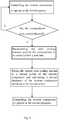
- the control method further comprises: after the first implementation, monitoring whether the compartment to be cooled has changed; if yes, then recalculating the total cooling amount needed by the compartment to be cooled within the unit time, taking the current total cooling amount as a second power of the inverter compressor, calculating a second frequency of the inverter compressor operating at the second power, and controlling the inverter compressor to operate at the second frequency; and if not, then controlling the inverter compressor to continue operating at the first frequency.
- Monitoring whether the compartment to be cooled has changed is to monitor whether a new cooling compartment is opened during the operation of the refrigerator and/or a cooling compartment is closed after reaching the target temperature, including but not limited to the following three situations: monitoring whether the state of the air door in the single-cooling system air-cooled refrigerator has changed; monitoring whether the cooling loop is shut down and/or started in a multi-cooling system air-cooled refrigerator and whether the state of the air door has changed; and monitoring whether the flow direction of the coolant in a multi-cooling system direct-cooling refrigerator has changed.
- the total cooling amount needed by the compartment to be cooled within a unit time is recalculated to control the inverter compressor to operate at the second frequency.
- the particular control method can be referred to the first implementation, which will not be described here anymore.
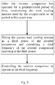
- Fig. 5 shows a control method of a refrigerator adopting a inverter compressor according to a second implementation of the present invention.
- the control method further comprises: after the inverter compressor has operated for a predetermined period of time, recalculating the total cooling amount needed by the compartment to be cooled within the unit time; taking the current total cooling amount as a third power of the inverter compressor and calculating a third frequency of the inverter compressor operating at the third power; and controlling the inverter compressor to operate at the third frequency.
- the temperature in the compartment of the refrigerator will gradually decrease. After the temperature of the compartment decreases, the total cooling amount of the refrigerator will decrease accordingly.
- the inverter compressor still operates at the first frequency, then it will cause the cooling amount generated by the compressor to be excessive, thus causing increased power consumption. Therefore, in this implementation, the total cooling amount needed by the compartment to be cooled within a unit time is recalculated after the inverter compressor has operated for a predetermined period of time. Then the frequency of the inverter compressor is controlled to be a third frequency according to the current total cooling amount, the third frequency being less than the first frequency.
- the "predetermined period of time” can be set according to different refrigerators and different operating environments, such as 30 min, 1h and so on.
- the refrigerator repeats the calculation of the total cooling amount every the predetermined period of time and updates the third frequency.
- the total cooling amount needed by the compartment to be cooled within the unit time can be calculated in real time so as to control the frequency of the inverter compressor to gradually decrease in real time.
- the present invention effectively controls the power consumption amount while satisfying the refrigerator cooling condition by calculating the total cooling amount needed by a refrigerator compartment within a unit time and adjusting the frequency of the inverter compressor.
Landscapes
- Engineering & Computer Science (AREA)
- Physics & Mathematics (AREA)
- Mechanical Engineering (AREA)
- Thermal Sciences (AREA)
- General Engineering & Computer Science (AREA)
- Chemical & Material Sciences (AREA)
- Combustion & Propulsion (AREA)
- Devices That Are Associated With Refrigeration Equipment (AREA)
Description
- The present invention relates to the technical field of refrigerator cooling control, and in particular to a refrigerator control method and control system with a inverter compressor.
- Refrigerators usually include multi-cooling system refrigerators (direct-cooling refrigerators) and single-cooling system refrigerators (air-cooled refrigerators). The multi-cooling system includes a plurality of cooling paths for the coolant to pass through and a inverter compressor connected to all cooling paths, each cooling path being provided with an evaporator. The single-cooling system includes a cooling path for the coolant to pass through and a inverter compressor connected to the cooling path, the cooling path being provided with an evaporator.
- In a multi-cooling system refrigerator applying multi-evaporator, the heating loads needed by the coolant when passing through different cooling paths are different, thus the needed cooling amount is different. In the prior art, the inverter compressor adopts the same input frequency despite the inverter compressor controls the coolant to pass through which path, which inevitably causes the cooling amount generated by the inverter compressor to be excessive when the coolant passes through some cooling paths, thus causing increased power consumption.
- In a single-cooling system air-cooled refrigerator applying a single evaporator, there is usually a through air door between the refrigeration compartment and the freezing compartment. When the refrigeration compartment needs to perform cooling, the air door will be opened. When the refrigeration compartment does not need to perform cooling, the air door will be closed. When the refrigeration air door is opened, the cooling amount provided by the inverter compressor needs to satisfy the cooling requirements of refrigeration and freezing. When the air door is closed, the cooling amount provided by the inverter compressor merely needs to satisfy the cooling requirements of the freezing compartment. In the prior art, despite the inverter compressor controls the air door to open or close, the inverter compressor adopts the same input frequency, which inevitably causes the cooling amount generated by the inverter compressor to be excessive when the coolant passes through some cooling paths, thus causing increased power consumption.
- Document
JP 2000 356447 - Document Brian Boughton et al. "An investigation of household refrigerator cabinet thermal loads", HVAC&R Research, vol. 2, no. 2, 1 April 1996, pages 135-147, XP055582841 discloses an analysis of cabinet loads for household refrigerator/freezer wherein the thermal load on the cabinet during closed door conditions is investigated.
- With respect to the defects in the prior art, the technical problem to be solved by the present invention is to provide a control method of a refrigerator with a inverter compressor to control the frequency of the inverter compressor.
- In order to solve the above technical problem, the technical solution of the present invention is implemented as follows.
- A control method of a refrigerator with a inverter compressor according to claim 1 is provided.
- Preferred embodiments of the invention are the subject matter of the dependent claims, whose content is to be understood as forming an integral part of the present description.
- The beneficial effects of the present invention are as follows: the present invention effectively controls the power consumption amount while satisfying the refrigerator cooling condition by calculating the total cooling amount needed by a refrigerator compartment within a unit time and adjusting the frequency of the inverter compressor.
-
-
Fig. 1 is a flowchart of a control method of a refrigerator adopting a inverter compressor according to a first implementation of the present invention. -
Fig. 2 is a modular diagram of a control system of a refrigerator adopting a inverter compressor according to a first implementation of the present invention. -
Fig. 3 is a flowchart of a method for determining a compartment to be cooled according to a first implementation of the present invention. -
Fig. 4 is a flowchart of a control method of a refrigerator adopting a inverter compressor according to a second implementation of the present invention. -
Fig. 5 is a flowchart of a control method of a refrigerator adopting a inverter compressor according to a third implementation of the present invention. - In order to make the purposes, technical solutions and advantages of the invention more clear, specific implementations of this invention are described in accompany with the drawings as follows. These preferred implementations are exemplified in the drawings. Implementations of this invention as illustrated in the drawings and described in accordance with the drawings are merely illustrative, and this invention is not limited to these implementations.
- It is to be noted that, in order to avoid blurring the invention because of unnecessary details, the drawings only show the structures and/or processing steps which are closely related to the solutions of this invention, but omit the other details with little relationship with this invention.
- In addition, it is also to be noted that, the terms "comprise" and "include" or any of their other variants aim to cover non-exclusive containing relationships, so that the processes, methods, articles or equipment including a series of elements not only include those elements, but also include other elements not explicitly listed, or also include elements inherent in these processes, methods, articles or equipment.
-
Fig. 1 shows a control method of a refrigerator adopting a inverter compressor according to a first implementation of the present invention. The control method comprises: calculating the total cooling amount needed by a compartment to be cooled within a unit time; taking the total cooling amount as a first power of the inverter compressor and calculating a first frequency of the inverter compressor operating at the first power; and controlling the inverter compressor to operate at the first frequency. - Accordingly,
Fig. 2 shows a control system of a refrigerator adopting a inverter compressor in this implementation. The control system comprises: atemperature monitoring device 100 and amain control board 200 connected to thetemperature monitoring device 100. Thetemperature monitoring device 100 comprises a first temperature monitoring device provided external to the refrigerator for monitoring the operating ambient temperature of the refrigerator and a plurality of second temperature monitoring devices respectively provided in the compartments of the refrigerator for monitoring the compartment temperature in the compartments. Themain control board 200 is configured for: calculating the total cooling amount needed by a compartment to be cooled within a unit time; taking the total cooling amount as a first power of the inverter compressor and calculating a first frequency of the inverter compressor operating at the first power; and controlling the inverter compressor to operate at the first frequency. - In the present invention, the heating load of the refrigerator is equal to the total cooling amount required by the compartments. As the compartments of the refrigerator are formed by the enclosure of heat conduction walls (foaming layers), the total cooling amount required by the compartments is the total heat conducted by the heat conduction walls. In order to maintain that the inverter compressor can satisfy the cooling condition of the refrigerator during operation and will not cause cooling amount waste, in this implementation, the total cooling amount of the compartments within a unit time is maintained to be equal to the instantaneous power of the inverter compressor.
- The calculation of the total cooling amount within the unit time includes the following steps: calculating the heat conducted by the heat conduction walls of each compartment to be cooled within a unit time, the calculation formula of the heat conducted by each heat conduction wall being: Φ=λAΔT/δ, where Φ is the heat conducted by the heat conduction wall within a unit time, A is the area of the heat conduction wall (m2), λ is the heat conduction rate of the heat conduction wall [w / (m•K)], δ is the thickness of the heat conduction wall (m), and ΔT is the temperature difference between two surfaces of the heat conduction wall (°C), that is, the difference between the ambient temperature and the compartment temperature; calculating the sum of the heat conducted by the heat conduction walls of each compartment to be cooled to obtain the cooling amount needed by the compartments to be cooled; and calculating the sum of the cooling amounts needed by the compartments to be cooled to obtain the total cooling amount.
- In this implementation, the heat conduction wall being a flat wall is taken as an example. With the above equation Φ=λAΔT/δ, the heat conducted by the heat conduction walls of each compartment within a unit time can be calculated. The sum of the heat conducted by all heat conduction walls within a unit time is the cooling amount of this compartment within a unit time. Each compartment usually includes 6 heat conduction walls, namely, the upper, lower, left, right, front and back heat conduction walls. The sum of the heat conduction by the 6 heat conduction walls is the cooling amount of this cooling compartment.
- It should be understood that in this implementation, each compartment having 6 heat conduction walls is taken as an example for description, and in other implementations, other number of heat conduction walls can also be set, which will be not be described here.
- Furthermore, as shown in
Fig. 3 , the method for determining the compartment to be cooled is: monitoring the compartment temperature T in each compartment; comparing the compartment temperature in the compartment to a preset compartment temperature threshold T0 corresponding to each compartment; and if the compartment temperature T is greater than the corresponding preset compartment temperature threshold T0, then deeming that the compartment needs to be cooled; and if the compartment temperature T is less than or equal to the corresponding preset compartment temperature threshold T0, then deeming that the compartment does not need to be cooled. - The present invention can be applied to various types of refrigerators, such as single-cooling system air-cooled refrigerators, multi-cooling system air-cooled refrigerators, multi-cooling system direct-cooling refrigerators and so on. Hereinafter, this implementation will be described further in conjunction with particular embodiments.
- In a first embodiment of the present invention, a single-cooling system air-cooled refrigerator is taken as an example for description. This refrigerator includes two compartments, i.e., a refrigeration compartment and a freezing compartment. An air door for controlling the cooling of the refrigeration compartment is provided between the refrigeration compartment and the freezing compartment. A first temperature monitoring device is provided external to the refrigerator for monitoring the operating ambient temperature of the refrigerator. A plurality of second temperature monitoring devices are provided in the refrigeration compartment and the freezing compartment of the refrigerator respectively for monitoring the compartment temperature in the compartment.
- The state of an air door in a cooling loop is determined according to the comparison of the compartment temperature detected by the second temperature monitoring device and a preset compartment temperature threshold. For example, in this embodiment, the preset temperature threshold T01 of the refrigeration compartment is 0°C, and the preset temperature threshold T02 of the freezing compartment is -15°C.
- If it is monitored that the compartment temperature of the freezing compartment is less than or equal to -15°C, it indicates that the freezing compartment does not need cooling. Then the inverter compressor will be shut down. If it is monitored that the compartment temperature of the freezing compartment is greater than -15°C, it indicates that the freezing compartment needs cooling. The compartment temperature of the refrigeration compartment will be further monitored. The following two situations are included.
- 1. If it is monitored that the compartment temperature of the refrigeration compartment is greater than 0°C, then the air door will be opened and the freezing compartment and the refrigeration compartment will be cooled simultaneously. At this moment: the total cooling amount needed by the refrigeration compartment and the freezing compartment within a unit time is calculated; the total cooling amount is taken as a first power of the inverter compressor and a first frequency of the inverter compressor operating at the first power is calculated; and the inverter compressor is controlled to operate at the first frequency.
- 2. If it is monitored that the compartment temperature of the refrigeration compartment is less than or equal to 0°C, then the air door will be closed and merely the freezing compartment will be cooled. At this moment: the total cooling amount needed by the freezing compartment within a unit time is calculated; the total cooling amount is taken as a first power of the inverter compressor and a first frequency of the inverter compressor operating at the first power is calculated; and the inverter compressor is controlled to operate at the first frequency.
- In a second embodiment of the present invention, a multi-cooling system air-cooled refrigerator is taken as an example for description. This refrigerator includes a plurality of cooling systems. Each cooling system includes two compartments, i.e., a refrigeration compartment and a freezing compartment. An air door for controlling the cooling of the refrigeration compartment is provided between each refrigeration compartment and each freezing compartment. A first temperature monitoring device is provided external to the refrigerator for monitoring the operating ambient temperature of the refrigerator. A plurality of second temperature monitoring devices is provided in the refrigeration compartment and the freezing compartment respectively for monitoring the compartment temperatures in the compartments.
- The cooling system to be cooled is determined according to the compartment temperature in the freezing compartments. The state of the air door in the corresponding cooling system is determined according to the compartment temperature of the refrigeration compartment in the cooling system to be cooled. Finally, the total cooling amount within a unit time is calculated to control the frequency of the inverter compressor. The control method of each cooling system is the same as the first embodiment, which will not be described here anymore.
- In a third embodiment of the present invention, a multi-cooling system direct-cooling refrigerator is taken as an example for description. For example, this refrigerator includes two compartments, i.e., a refrigeration compartment and a freezing compartment. The coolant flows to the refrigeration compartment and the freezing compartment respectively. A first temperature monitoring device is provided external to the refrigerator for monitoring the operating ambient temperature of the refrigerator. A plurality of second temperature monitoring devices are provided in the refrigeration compartment and the freezing compartment of the refrigerator respectively for monitoring the compartment temperatures in the compartments.
- The flow direction of the coolant is determined according to the comparison of the compartment temperature detected by the second temperature monitoring device and a preset compartment temperature threshold. For example, in this embodiment, the preset temperature threshold T01 of the refrigeration compartment is 0°C, and the preset temperature threshold T02 of the freezing compartment is -15°C.
- If it is monitored that the compartment temperature of the freezing compartment is less than or equal to -15°C, it indicates that the freezing compartment does not need cooling, otherwise, the freezing compartment needs cooling. If it is monitored that the compartment temperature of the refrigeration compartment is less than or equal to 0°C, it indicates that the refrigeration compartment does not need cooling. Otherwise, the refrigeration compartment needs cooling.
- The control method includes: after the compartment to be cooled and the flow direction of the coolant are determined, calculating the total cooling amount needed by the refrigeration compartment and/or the freezing compartment within the unit time; taking the total cooling amount as a first power of the inverter compressor and calculating a first frequency of the inverter compressor operating at the first power; and controlling the inverter compressor to operate at the first frequency.
-
Fig. 4 shows a control method of a refrigerator adopting a inverter compressor according to a second implementation of the present invention. The control method further comprises: after the first implementation, monitoring whether the compartment to be cooled has changed; if yes, then recalculating the total cooling amount needed by the compartment to be cooled within the unit time, taking the current total cooling amount as a second power of the inverter compressor, calculating a second frequency of the inverter compressor operating at the second power, and controlling the inverter compressor to operate at the second frequency; and if not, then controlling the inverter compressor to continue operating at the first frequency. - "Monitoring whether the compartment to be cooled has changed" is to monitor whether a new cooling compartment is opened during the operation of the refrigerator and/or a cooling compartment is closed after reaching the target temperature, including but not limited to the following three situations: monitoring whether the state of the air door in the single-cooling system air-cooled refrigerator has changed; monitoring whether the cooling loop is shut down and/or started in a multi-cooling system air-cooled refrigerator and whether the state of the air door has changed; and monitoring whether the flow direction of the coolant in a multi-cooling system direct-cooling refrigerator has changed.
- In the first to the third implementations, if there is a new cooling compartment opened and/or a cooling compartment is closed after reaching the target temperature, then the total cooling amount needed by the compartment to be cooled within a unit time is recalculated to control the inverter compressor to operate at the second frequency. The particular control method can be referred to the first implementation, which will not be described here anymore.
-
Fig. 5 shows a control method of a refrigerator adopting a inverter compressor according to a second implementation of the present invention. After the first implementation, the control method further comprises: after the inverter compressor has operated for a predetermined period of time, recalculating the total cooling amount needed by the compartment to be cooled within the unit time; taking the current total cooling amount as a third power of the inverter compressor and calculating a third frequency of the inverter compressor operating at the third power; and controlling the inverter compressor to operate at the third frequency. - In particular, when the refrigerator operates, the temperature in the compartment of the refrigerator will gradually decrease. After the temperature of the compartment decreases, the total cooling amount of the refrigerator will decrease accordingly. At this moment, if the inverter compressor still operates at the first frequency, then it will cause the cooling amount generated by the compressor to be excessive, thus causing increased power consumption. Therefore, in this implementation, the total cooling amount needed by the compartment to be cooled within a unit time is recalculated after the inverter compressor has operated for a predetermined period of time. Then the frequency of the inverter compressor is controlled to be a third frequency according to the current total cooling amount, the third frequency being less than the first frequency.
- In addition, in this implementation, the "predetermined period of time" can be set according to different refrigerators and different operating environments, such as 30 min, 1h and so on. The refrigerator repeats the calculation of the total cooling amount every the predetermined period of time and updates the third frequency.
- It should be understood that in other implementations of the present invention, the total cooling amount needed by the compartment to be cooled within the unit time can be calculated in real time so as to control the frequency of the inverter compressor to gradually decrease in real time.
- It can be seen from the above technical solutions that the present invention effectively controls the power consumption amount while satisfying the refrigerator cooling condition by calculating the total cooling amount needed by a refrigerator compartment within a unit time and adjusting the frequency of the inverter compressor.
- It should be understood that, although the specification is described in accordance with implementations, not every implementation only contains a separate technical solution. This sort of narrative description manner in the specification is just for the sake of clarity. Those skilled in the art should take the specification as a whole. The technical solution in each implementation can also be combined to form other implementations which those skilled in the art can understand.
- The above detailed descriptions are only specific for the feasible implementations of the present application. They are not used to limit the protection scope of the present invention, which is to be limited only by the scope of the claims.
Claims (4)
- A control method of a refrigerator adopting a inverter compressor, the refrigerator is configured as a multi-cooling system air-cooled refrigerator, the multi-cooling system air-cooled refrigerator comprising a plurality of cooling systems, each cooling system comprising a refrigeration compartment and a freezing compartment, an air door for controlling the cooling of the refrigeration compartment being provided between each refrigeration compartment and each freezing compartment, the control method comprising:calculating the total cooling amount needed by a compartment to be cooled within a unit time;taking the total cooling amount as a first power of the inverter compressor and calculating a first frequency of the inverter compressor operating at the first power; andcontrolling the inverter compressor to operate at the first frequency; characterized in that, .the method for determining the compartment to be cooled is:monitoring the compartment temperature (T) in each compartment;comparing the compartment temperature in the compartment to a preset compartment temperature threshold (TO) corresponding to each compartment; andif the compartment temperature (T) is greater than the corresponding preset compartment temperature threshold (TO), then deeming that the compartment needs to be cooled; and if the compartment temperature (T) is less than or equal to the corresponding preset compartment temperature threshold (TO), then deeming that the compartment does not need to be cooled;monitoring whether the compartment to be cooled has changed; andif yes, then recalculating the total cooling amount needed by the compartment to be cooled within the unit time, taking the current total cooling amount as a second power of the inverter compressor, calculating a second frequency of the inverter compressor operating at the second power, and controlling the inverter compressor to operate at the second frequency; and if not, then controlling the inverter compressor to continue operating at the first frequency;monitoring whether the compartment to be cooled has changed comprises:
monitoring whether at least one of the states of the air doors in the cooling loops of the multi-cooling system air-cooled refrigerator has changed. - A control method of a refrigerator adopting a inverter compressor, the refrigerator is configured as a single-cooling system air-cooled refrigerator, the single-cooling system air-cooled refrigerator comprising a refrigeration compartment and a freezing compartment, an air door for controlling the cooling of the refrigeration compartment being provided between the refrigeration compartment and the freezing compartment, the control method comprising:calculating the total cooling amount needed by a compartment to be cooled within a unit time;taking the total cooling amount as a first power of the inverter compressor and calculating a first frequency of the inverter compressor operating at the first power; andcontrolling the inverter compressor to operate at the first frequency; characterized in that, .the method for determining the compartment to be cooled is:monitoring the compartment temperature (T) in each compartment;comparing the compartment temperature in the compartment to a preset compartment temperature threshold (TO) corresponding to each compartment; andif the compartment temperature (T) is greater than the corresponding preset compartment temperature threshold (TO), then deeming that the compartment needs to be cooled; and if the compartment temperature (T) is less than or equal to the corresponding preset compartment temperature threshold (TO), then deeming that the compartment does not need to be cooled;monitoring whether the compartment to be cooled has changed; andif yes, then recalculating the total cooling amount needed by the compartment to be cooled within the unit time, taking the current total cooling amount as a second power of the inverter compressor, calculating a second frequency of the inverter compressor operating at the second power, and controlling the inverter compressor to operate at the second frequency; and if not, then controlling the inverter compressor to continue operating at the first frequency;monitoring whether the compartment to be cooled has changed comprises:
monitoring whether the state of an air door in a cooling loop of the single-cooling system air-cooled refrigerator has changed. - The control method according to claim 1 or 2, wherein calculating the total cooling amount needed by the compartment to be cooled within the unit time comprises:calculating the heat conducted by the heat conduction walls of each compartment to be cooled within the unit time, the calculation formula of the heat conducted by each heat conduction wall being:
 where Φ is the heat conducted by the heat conduction wall within the unit time, A is the area of the heat conduction wall, λ is the heat conduction rate of the heat conduction wall, δ is the thickness of the heat conduction wall, and ΔT is the temperature difference between two surfaces of the heat conduction wall, that is, the difference between the ambient temperature and the compartment temperature;calculating the sum of the heat conducted by the heat conduction walls of each compartment to be cooled to obtain the cooling amount needed by the compartments to be cooled; and
calculating the sum of the cooling amounts needed by the compartments to be cooled to obtain the total cooling amount. - The control method according to claim 1 or 2, further comprising:after the inverter compressor has operated for a predetermined period of time, recalculating the total cooling amount needed by the compartment to be cooled within the unit time;taking the current total cooling amount as a third power of the inverter compressor and calculating a third frequency of the inverter compressor operating at the third power; andcontrolling the inverter compressor to operate at the third frequency.
Applications Claiming Priority (2)
| Application Number | Priority Date | Filing Date | Title |
|---|---|---|---|
| CN201510746342.2A CN105258445B (en) | 2015-11-05 | 2015-11-05 | Using the controlling method for refrigerator and control system of frequency-changeable compressor |
| PCT/CN2016/086166 WO2017076001A1 (en) | 2015-11-05 | 2016-06-17 | Refrigerator control method and control system adopting variable frequency compressor |
Publications (3)
| Publication Number | Publication Date |
|---|---|
| EP3372931A1 EP3372931A1 (en) | 2018-09-12 |
| EP3372931A4 EP3372931A4 (en) | 2019-05-29 |
| EP3372931B1 true EP3372931B1 (en) | 2021-03-17 |
Family
ID=55098235
Family Applications (1)
| Application Number | Title | Priority Date | Filing Date |
|---|---|---|---|
| EP16861271.1A Active EP3372931B1 (en) | 2015-11-05 | 2016-06-17 | Refrigerator control method adopting variable frequency compressor |
Country Status (4)
| Country | Link |
|---|---|
| US (1) | US10739066B2 (en) |
| EP (1) | EP3372931B1 (en) |
| CN (1) | CN105258445B (en) |
| WO (1) | WO2017076001A1 (en) |
Families Citing this family (16)
| Publication number | Priority date | Publication date | Assignee | Title |
|---|---|---|---|---|
| CN105258445B (en) * | 2015-11-05 | 2018-02-02 | 青岛海尔股份有限公司 | Using the controlling method for refrigerator and control system of frequency-changeable compressor |
| CN108302895A (en) * | 2018-01-08 | 2018-07-20 | 合肥华凌股份有限公司 | The energy-saving control method and refrigerator of refrigerator |
| CN108759290B (en) * | 2018-06-07 | 2020-06-09 | 长虹美菱股份有限公司 | A frequency control method of frequency conversion refrigerator compressor |
| CN109827379A (en) * | 2019-01-29 | 2019-05-31 | 长虹美菱股份有限公司 | A kind of wide revolving speed motor control method applied to refrigerator |
| CN110953775B (en) * | 2019-11-21 | 2021-08-17 | 海信(山东)冰箱有限公司 | A kind of refrigeration equipment and refrigeration equipment control method |
| CN113280561B (en) * | 2020-02-20 | 2022-12-13 | 佛山市云米电器科技有限公司 | Refrigerator control method, refrigerator and computer-readable storage medium |
| CN111156769A (en) * | 2020-03-04 | 2020-05-15 | 江苏元隆电器有限公司 | Intelligent control method of variable frequency refrigerator |
| CN111442479A (en) * | 2020-04-02 | 2020-07-24 | 青岛海尔空调器有限总公司 | Method and air conditioner for controlling air conditioner |
| CN111854317A (en) * | 2020-06-29 | 2020-10-30 | 珠海格力电器股份有限公司 | Refrigerator control method and device for effectively improving temperature control precision and refrigerator |
| CN113915849B (en) * | 2020-07-09 | 2023-06-16 | 海信冰箱有限公司 | Refrigerator energy-saving control method |
| CN114061253B (en) * | 2020-08-04 | 2023-01-20 | 青岛海尔电冰箱有限公司 | Control method of single-system refrigerator |
| CN112413973B (en) * | 2020-11-25 | 2021-10-08 | 珠海格力电器股份有限公司 | Control method of refrigerated cabinet and refrigerating system |
| CN112460910B (en) * | 2020-12-07 | 2021-11-12 | 珠海格力电器股份有限公司 | Control method of refrigerator compressor and refrigerator |
| CN112682989B (en) * | 2020-12-29 | 2021-12-03 | 珠海格力电器股份有限公司 | Compressor rotating speed control method, device and equipment and refrigerator |
| CN115435543B (en) * | 2021-06-02 | 2023-07-21 | 青岛海尔生物医疗股份有限公司 | Method and device for controlling variable frequency compressor of refrigerator and refrigerator |
| CN116067062B (en) * | 2021-11-02 | 2025-08-12 | 海信容声(广东)冰箱有限公司 | Refrigerator, variable frequency compressor system and control method of variable frequency compressor system |
Family Cites Families (19)
| Publication number | Priority date | Publication date | Assignee | Title |
|---|---|---|---|---|
| US5711159A (en) * | 1994-09-07 | 1998-01-27 | General Electric Company | Energy-efficient refrigerator control system |
| JP2000356447A (en) * | 1999-06-14 | 2000-12-26 | Matsushita Refrig Co Ltd | Inverter for refrigerating system |
| US7984617B2 (en) * | 2003-10-29 | 2011-07-26 | Lg Electronics Inc. | Method of controlling compressor for refrigerator and apparatus thereof |
| KR100579564B1 (en) * | 2004-04-12 | 2006-05-15 | 엘지전자 주식회사 | Control method of electronic expansion valve of refrigeration cycle unit |
| JP2005300098A (en) * | 2004-04-15 | 2005-10-27 | Matsushita Electric Ind Co Ltd | refrigerator |
| US8136365B2 (en) * | 2007-07-02 | 2012-03-20 | Hoshizaki Denki Kabushiki Kaisha | Cooling apparatus having a variable speed compressor with speed limited on the basis of a sensed performance parameter |
| US8539786B2 (en) | 2007-10-08 | 2013-09-24 | Emerson Climate Technologies, Inc. | System and method for monitoring overheat of a compressor |
| KR101436642B1 (en) * | 2008-02-20 | 2014-09-02 | 엘지전자 주식회사 | Motor control apparatus and linear compressor using the same |
| CN101363653A (en) * | 2008-08-22 | 2009-02-11 | 日滔贸易(上海)有限公司 | Energy consumption control method and device of central air-conditioning refrigeration system |
| CN101603751B (en) * | 2009-07-15 | 2013-07-10 | 北京科技大学 | Variable frequency energy-saving control method for refrigeration system |
| CN102128481B (en) * | 2010-01-20 | 2013-03-20 | 珠海格力电器股份有限公司 | Air conditioner and control method and device thereof |
| EP2833082A4 (en) * | 2012-03-29 | 2016-01-06 | Mitsubishi Electric Corp | AIR CONDITIONING DEVICE |
| CN102735018B (en) * | 2012-06-26 | 2014-09-10 | 四川长虹电器股份有限公司 | Method for controlling temperature of mechanical refrigerator in frequency conversion mode |
| CN202709632U (en) * | 2012-06-26 | 2013-01-30 | 四川长虹电器股份有限公司 | Mechanical refrigerator frequency conversion temperature regulating device |
| US9453661B2 (en) * | 2013-03-12 | 2016-09-27 | Haier US Appliance Solutions, Inc | Control system for a dual evaporator refrigeration system |
| CN104515245B (en) * | 2013-09-26 | 2017-06-30 | 珠海格力电器股份有限公司 | control method and device of air conditioning system |
| CN104279836B (en) * | 2014-10-29 | 2017-05-17 | 珠海格力电器股份有限公司 | Control method and device and refrigeration equipment |
| CN104990222B (en) * | 2015-07-15 | 2017-10-27 | 广东美的暖通设备有限公司 | Air conditioning control method and device |
| CN105258445B (en) | 2015-11-05 | 2018-02-02 | 青岛海尔股份有限公司 | Using the controlling method for refrigerator and control system of frequency-changeable compressor |
-
2015
- 2015-11-05 CN CN201510746342.2A patent/CN105258445B/en active Active
-
2016
- 2016-06-17 EP EP16861271.1A patent/EP3372931B1/en active Active
- 2016-06-17 WO PCT/CN2016/086166 patent/WO2017076001A1/en not_active Ceased
- 2016-06-17 US US15/770,202 patent/US10739066B2/en active Active
Non-Patent Citations (1)
| Title |
|---|
| None * |
Also Published As
| Publication number | Publication date |
|---|---|
| CN105258445A (en) | 2016-01-20 |
| EP3372931A4 (en) | 2019-05-29 |
| US20180266755A1 (en) | 2018-09-20 |
| EP3372931A1 (en) | 2018-09-12 |
| WO2017076001A1 (en) | 2017-05-11 |
| CN105258445B (en) | 2018-02-02 |
| US10739066B2 (en) | 2020-08-11 |
Similar Documents
| Publication | Publication Date | Title |
|---|---|---|
| EP3372931A1 (en) | Refrigerator control method and control system adopting variable frequency compressor | |
| US9140479B2 (en) | Synchronous temperature rate control and apparatus for refrigeration with reduced energy consumption | |
| US9810472B2 (en) | Synchronous temperature rate control for refrigeration with reduced energy consumption | |
| EP3306241A1 (en) | Refrigerator | |
| US9140477B2 (en) | Synchronous compartment temperature control and apparatus for refrigeration with reduced energy consumption | |
| KR20180055242A (en) | Refrigerator and control method of the same | |
| EP2124000A1 (en) | Cooling storage building and method of operating the same | |
| US20170038129A1 (en) | Refrigerator and method of controlling the same | |
| WO2014163831A1 (en) | Dual evaporator refrigerator appliance and method of operating the same | |
| US11578911B2 (en) | Freezer case with variable superheat setpoints | |
| CN113503673A (en) | Control method of refrigeration storage equipment and refrigeration storage equipment | |
| JP2000146398A (en) | Refrigerator control device | |
| JP6502773B2 (en) | Cold storage device | |
| CN115479446B (en) | Temperature control methods, electronic equipment and direct cooling refrigeration devices | |
| JP2009236347A (en) | Cooling storage cabinet | |
| WO2023006489A1 (en) | Refrigerator and method therefor | |
| JP2019191841A (en) | Temperature controller for warm/cold storage | |
| CN112815617A (en) | Control method and device of single-system refrigerator, single-system refrigerator and storage medium | |
| JP2014055703A (en) | Refrigerator | |
| JP7780736B2 (en) | Cooling time prediction system | |
| JP7780737B2 (en) | Cooling time prediction system | |
| CN115479445B (en) | Temperature control method, electronic equipment and direct-cooling type refrigerating device | |
| EP2806237B1 (en) | Method for cooling a refrigerated system and refrigerator. | |
| TR2022018926A2 (en) | A refrigerating device and its method of operation. | |
| CN120777833A (en) | Control method and device for refrigerator, refrigerator and computer-readable storage medium |
Legal Events
| Date | Code | Title | Description |
|---|---|---|---|
| STAA | Information on the status of an ep patent application or granted ep patent |
Free format text: STATUS: THE INTERNATIONAL PUBLICATION HAS BEEN MADE |
|
| PUAI | Public reference made under article 153(3) epc to a published international application that has entered the european phase |
Free format text: ORIGINAL CODE: 0009012 |
|
| STAA | Information on the status of an ep patent application or granted ep patent |
Free format text: STATUS: REQUEST FOR EXAMINATION WAS MADE |
|
| 17P | Request for examination filed |
Effective date: 20180504 |
|
| AK | Designated contracting states |
Kind code of ref document: A1 Designated state(s): AL AT BE BG CH CY CZ DE DK EE ES FI FR GB GR HR HU IE IS IT LI LT LU LV MC MK MT NL NO PL PT RO RS SE SI SK SM TR |
|
| AX | Request for extension of the european patent |
Extension state: BA ME |
|
| DAV | Request for validation of the european patent (deleted) | ||
| DAX | Request for extension of the european patent (deleted) | ||
| A4 | Supplementary search report drawn up and despatched |
Effective date: 20190502 |
|
| RIC1 | Information provided on ipc code assigned before grant |
Ipc: F25D 29/00 20060101AFI20190425BHEP |
|
| GRAP | Despatch of communication of intention to grant a patent |
Free format text: ORIGINAL CODE: EPIDOSNIGR1 |
|
| STAA | Information on the status of an ep patent application or granted ep patent |
Free format text: STATUS: GRANT OF PATENT IS INTENDED |
|
| INTG | Intention to grant announced |
Effective date: 20200619 |
|
| GRAS | Grant fee paid |
Free format text: ORIGINAL CODE: EPIDOSNIGR3 |
|
| GRAJ | Information related to disapproval of communication of intention to grant by the applicant or resumption of examination proceedings by the epo deleted |
Free format text: ORIGINAL CODE: EPIDOSDIGR1 |
|
| GRAL | Information related to payment of fee for publishing/printing deleted |
Free format text: ORIGINAL CODE: EPIDOSDIGR3 |
|
| STAA | Information on the status of an ep patent application or granted ep patent |
Free format text: STATUS: REQUEST FOR EXAMINATION WAS MADE |
|
| INTC | Intention to grant announced (deleted) | ||
| GRAP | Despatch of communication of intention to grant a patent |
Free format text: ORIGINAL CODE: EPIDOSNIGR1 |
|
| STAA | Information on the status of an ep patent application or granted ep patent |
Free format text: STATUS: GRANT OF PATENT IS INTENDED |
|
| INTG | Intention to grant announced |
Effective date: 20201130 |
|
| GRAA | (expected) grant |
Free format text: ORIGINAL CODE: 0009210 |
|
| STAA | Information on the status of an ep patent application or granted ep patent |
Free format text: STATUS: THE PATENT HAS BEEN GRANTED |
|
| AK | Designated contracting states |
Kind code of ref document: B1 Designated state(s): AL AT BE BG CH CY CZ DE DK EE ES FI FR GB GR HR HU IE IS IT LI LT LU LV MC MK MT NL NO PL PT RO RS SE SI SK SM TR |
|
| REG | Reference to a national code |
Ref country code: GB Ref legal event code: FG4D |
|
| REG | Reference to a national code |
Ref country code: CH Ref legal event code: EP |
|
| REG | Reference to a national code |
Ref country code: DE Ref legal event code: R096 Ref document number: 602016054599 Country of ref document: DE |
|
| REG | Reference to a national code |
Ref country code: IE Ref legal event code: FG4D |
|
| REG | Reference to a national code |
Ref country code: AT Ref legal event code: REF Ref document number: 1372623 Country of ref document: AT Kind code of ref document: T Effective date: 20210415 |
|
| REG | Reference to a national code |
Ref country code: LT Ref legal event code: MG9D |
|
| PG25 | Lapsed in a contracting state [announced via postgrant information from national office to epo] |
Ref country code: FI Free format text: LAPSE BECAUSE OF FAILURE TO SUBMIT A TRANSLATION OF THE DESCRIPTION OR TO PAY THE FEE WITHIN THE PRESCRIBED TIME-LIMIT Effective date: 20210317 Ref country code: GR Free format text: LAPSE BECAUSE OF FAILURE TO SUBMIT A TRANSLATION OF THE DESCRIPTION OR TO PAY THE FEE WITHIN THE PRESCRIBED TIME-LIMIT Effective date: 20210618 Ref country code: HR Free format text: LAPSE BECAUSE OF FAILURE TO SUBMIT A TRANSLATION OF THE DESCRIPTION OR TO PAY THE FEE WITHIN THE PRESCRIBED TIME-LIMIT Effective date: 20210317 Ref country code: NO Free format text: LAPSE BECAUSE OF FAILURE TO SUBMIT A TRANSLATION OF THE DESCRIPTION OR TO PAY THE FEE WITHIN THE PRESCRIBED TIME-LIMIT Effective date: 20210617 Ref country code: BG Free format text: LAPSE BECAUSE OF FAILURE TO SUBMIT A TRANSLATION OF THE DESCRIPTION OR TO PAY THE FEE WITHIN THE PRESCRIBED TIME-LIMIT Effective date: 20210617 |
|
| REG | Reference to a national code |
Ref country code: AT Ref legal event code: MK05 Ref document number: 1372623 Country of ref document: AT Kind code of ref document: T Effective date: 20210317 |
|
| REG | Reference to a national code |
Ref country code: NL Ref legal event code: MP Effective date: 20210317 |
|
| PG25 | Lapsed in a contracting state [announced via postgrant information from national office to epo] |
Ref country code: SE Free format text: LAPSE BECAUSE OF FAILURE TO SUBMIT A TRANSLATION OF THE DESCRIPTION OR TO PAY THE FEE WITHIN THE PRESCRIBED TIME-LIMIT Effective date: 20210317 Ref country code: RS Free format text: LAPSE BECAUSE OF FAILURE TO SUBMIT A TRANSLATION OF THE DESCRIPTION OR TO PAY THE FEE WITHIN THE PRESCRIBED TIME-LIMIT Effective date: 20210317 Ref country code: LV Free format text: LAPSE BECAUSE OF FAILURE TO SUBMIT A TRANSLATION OF THE DESCRIPTION OR TO PAY THE FEE WITHIN THE PRESCRIBED TIME-LIMIT Effective date: 20210317 |
|
| PG25 | Lapsed in a contracting state [announced via postgrant information from national office to epo] |
Ref country code: NL Free format text: LAPSE BECAUSE OF FAILURE TO SUBMIT A TRANSLATION OF THE DESCRIPTION OR TO PAY THE FEE WITHIN THE PRESCRIBED TIME-LIMIT Effective date: 20210317 |
|
| PG25 | Lapsed in a contracting state [announced via postgrant information from national office to epo] |
Ref country code: LT Free format text: LAPSE BECAUSE OF FAILURE TO SUBMIT A TRANSLATION OF THE DESCRIPTION OR TO PAY THE FEE WITHIN THE PRESCRIBED TIME-LIMIT Effective date: 20210317 Ref country code: CZ Free format text: LAPSE BECAUSE OF FAILURE TO SUBMIT A TRANSLATION OF THE DESCRIPTION OR TO PAY THE FEE WITHIN THE PRESCRIBED TIME-LIMIT Effective date: 20210317 Ref country code: EE Free format text: LAPSE BECAUSE OF FAILURE TO SUBMIT A TRANSLATION OF THE DESCRIPTION OR TO PAY THE FEE WITHIN THE PRESCRIBED TIME-LIMIT Effective date: 20210317 Ref country code: AT Free format text: LAPSE BECAUSE OF FAILURE TO SUBMIT A TRANSLATION OF THE DESCRIPTION OR TO PAY THE FEE WITHIN THE PRESCRIBED TIME-LIMIT Effective date: 20210317 Ref country code: SM Free format text: LAPSE BECAUSE OF FAILURE TO SUBMIT A TRANSLATION OF THE DESCRIPTION OR TO PAY THE FEE WITHIN THE PRESCRIBED TIME-LIMIT Effective date: 20210317 |
|
| PG25 | Lapsed in a contracting state [announced via postgrant information from national office to epo] |
Ref country code: IS Free format text: LAPSE BECAUSE OF FAILURE TO SUBMIT A TRANSLATION OF THE DESCRIPTION OR TO PAY THE FEE WITHIN THE PRESCRIBED TIME-LIMIT Effective date: 20210717 Ref country code: PT Free format text: LAPSE BECAUSE OF FAILURE TO SUBMIT A TRANSLATION OF THE DESCRIPTION OR TO PAY THE FEE WITHIN THE PRESCRIBED TIME-LIMIT Effective date: 20210719 Ref country code: PL Free format text: LAPSE BECAUSE OF FAILURE TO SUBMIT A TRANSLATION OF THE DESCRIPTION OR TO PAY THE FEE WITHIN THE PRESCRIBED TIME-LIMIT Effective date: 20210317 Ref country code: SK Free format text: LAPSE BECAUSE OF FAILURE TO SUBMIT A TRANSLATION OF THE DESCRIPTION OR TO PAY THE FEE WITHIN THE PRESCRIBED TIME-LIMIT Effective date: 20210317 Ref country code: RO Free format text: LAPSE BECAUSE OF FAILURE TO SUBMIT A TRANSLATION OF THE DESCRIPTION OR TO PAY THE FEE WITHIN THE PRESCRIBED TIME-LIMIT Effective date: 20210317 |
|
| REG | Reference to a national code |
Ref country code: DE Ref legal event code: R097 Ref document number: 602016054599 Country of ref document: DE |
|
| PLBE | No opposition filed within time limit |
Free format text: ORIGINAL CODE: 0009261 |
|
| STAA | Information on the status of an ep patent application or granted ep patent |
Free format text: STATUS: NO OPPOSITION FILED WITHIN TIME LIMIT |
|
| PG25 | Lapsed in a contracting state [announced via postgrant information from national office to epo] |
Ref country code: DK Free format text: LAPSE BECAUSE OF FAILURE TO SUBMIT A TRANSLATION OF THE DESCRIPTION OR TO PAY THE FEE WITHIN THE PRESCRIBED TIME-LIMIT Effective date: 20210317 Ref country code: AL Free format text: LAPSE BECAUSE OF FAILURE TO SUBMIT A TRANSLATION OF THE DESCRIPTION OR TO PAY THE FEE WITHIN THE PRESCRIBED TIME-LIMIT Effective date: 20210317 Ref country code: MC Free format text: LAPSE BECAUSE OF FAILURE TO SUBMIT A TRANSLATION OF THE DESCRIPTION OR TO PAY THE FEE WITHIN THE PRESCRIBED TIME-LIMIT Effective date: 20210317 Ref country code: ES Free format text: LAPSE BECAUSE OF FAILURE TO SUBMIT A TRANSLATION OF THE DESCRIPTION OR TO PAY THE FEE WITHIN THE PRESCRIBED TIME-LIMIT Effective date: 20210317 |
|
| REG | Reference to a national code |
Ref country code: CH Ref legal event code: PL |
|
| 26N | No opposition filed |
Effective date: 20211220 |
|
| PG25 | Lapsed in a contracting state [announced via postgrant information from national office to epo] |
Ref country code: SI Free format text: LAPSE BECAUSE OF FAILURE TO SUBMIT A TRANSLATION OF THE DESCRIPTION OR TO PAY THE FEE WITHIN THE PRESCRIBED TIME-LIMIT Effective date: 20210317 |
|
| REG | Reference to a national code |
Ref country code: BE Ref legal event code: MM Effective date: 20210630 |
|
| PG25 | Lapsed in a contracting state [announced via postgrant information from national office to epo] |
Ref country code: LU Free format text: LAPSE BECAUSE OF NON-PAYMENT OF DUE FEES Effective date: 20210617 |
|
| PG25 | Lapsed in a contracting state [announced via postgrant information from national office to epo] |
Ref country code: LI Free format text: LAPSE BECAUSE OF NON-PAYMENT OF DUE FEES Effective date: 20210630 Ref country code: IT Free format text: LAPSE BECAUSE OF FAILURE TO SUBMIT A TRANSLATION OF THE DESCRIPTION OR TO PAY THE FEE WITHIN THE PRESCRIBED TIME-LIMIT Effective date: 20210317 Ref country code: IE Free format text: LAPSE BECAUSE OF NON-PAYMENT OF DUE FEES Effective date: 20210617 Ref country code: CH Free format text: LAPSE BECAUSE OF NON-PAYMENT OF DUE FEES Effective date: 20210630 |
|
| PG25 | Lapsed in a contracting state [announced via postgrant information from national office to epo] |
Ref country code: IS Free format text: LAPSE BECAUSE OF FAILURE TO SUBMIT A TRANSLATION OF THE DESCRIPTION OR TO PAY THE FEE WITHIN THE PRESCRIBED TIME-LIMIT Effective date: 20210717 |
|
| PG25 | Lapsed in a contracting state [announced via postgrant information from national office to epo] |
Ref country code: BE Free format text: LAPSE BECAUSE OF NON-PAYMENT OF DUE FEES Effective date: 20210630 |
|
| PG25 | Lapsed in a contracting state [announced via postgrant information from national office to epo] |
Ref country code: CY Free format text: LAPSE BECAUSE OF FAILURE TO SUBMIT A TRANSLATION OF THE DESCRIPTION OR TO PAY THE FEE WITHIN THE PRESCRIBED TIME-LIMIT Effective date: 20210317 |
|
| PG25 | Lapsed in a contracting state [announced via postgrant information from national office to epo] |
Ref country code: HU Free format text: LAPSE BECAUSE OF FAILURE TO SUBMIT A TRANSLATION OF THE DESCRIPTION OR TO PAY THE FEE WITHIN THE PRESCRIBED TIME-LIMIT; INVALID AB INITIO Effective date: 20160617 |
|
| PG25 | Lapsed in a contracting state [announced via postgrant information from national office to epo] |
Ref country code: MK Free format text: LAPSE BECAUSE OF FAILURE TO SUBMIT A TRANSLATION OF THE DESCRIPTION OR TO PAY THE FEE WITHIN THE PRESCRIBED TIME-LIMIT Effective date: 20210317 |
|
| PG25 | Lapsed in a contracting state [announced via postgrant information from national office to epo] |
Ref country code: TR Free format text: LAPSE BECAUSE OF FAILURE TO SUBMIT A TRANSLATION OF THE DESCRIPTION OR TO PAY THE FEE WITHIN THE PRESCRIBED TIME-LIMIT Effective date: 20210317 |
|
| PG25 | Lapsed in a contracting state [announced via postgrant information from national office to epo] |
Ref country code: MT Free format text: LAPSE BECAUSE OF FAILURE TO SUBMIT A TRANSLATION OF THE DESCRIPTION OR TO PAY THE FEE WITHIN THE PRESCRIBED TIME-LIMIT Effective date: 20210317 |
|
| PGFP | Annual fee paid to national office [announced via postgrant information from national office to epo] |
Ref country code: DE Payment date: 20250617 Year of fee payment: 10 |
|
| PGFP | Annual fee paid to national office [announced via postgrant information from national office to epo] |
Ref country code: GB Payment date: 20250625 Year of fee payment: 10 |
|
| PGFP | Annual fee paid to national office [announced via postgrant information from national office to epo] |
Ref country code: FR Payment date: 20250630 Year of fee payment: 10 |