EP3372874A1 - Rotary seal - Google Patents
Rotary seal Download PDFInfo
- Publication number
- EP3372874A1 EP3372874A1 EP18159693.3A EP18159693A EP3372874A1 EP 3372874 A1 EP3372874 A1 EP 3372874A1 EP 18159693 A EP18159693 A EP 18159693A EP 3372874 A1 EP3372874 A1 EP 3372874A1
- Authority
- EP
- European Patent Office
- Prior art keywords
- sliding contact
- slinger
- seal
- core metal
- rsk
- Prior art date
- Legal status (The legal status is an assumption and is not a legal conclusion. Google has not performed a legal analysis and makes no representation as to the accuracy of the status listed.)
- Granted
Links
Images


Classifications
-
- F—MECHANICAL ENGINEERING; LIGHTING; HEATING; WEAPONS; BLASTING
- F16—ENGINEERING ELEMENTS AND UNITS; GENERAL MEASURES FOR PRODUCING AND MAINTAINING EFFECTIVE FUNCTIONING OF MACHINES OR INSTALLATIONS; THERMAL INSULATION IN GENERAL
- F16C—SHAFTS; FLEXIBLE SHAFTS; ELEMENTS OR CRANKSHAFT MECHANISMS; ROTARY BODIES OTHER THAN GEARING ELEMENTS; BEARINGS
- F16C33/00—Parts of bearings; Special methods for making bearings or parts thereof
- F16C33/72—Sealings
- F16C33/76—Sealings of ball or roller bearings
- F16C33/78—Sealings of ball or roller bearings with a diaphragm, disc, or ring, with or without resilient members
- F16C33/7889—Sealings of ball or roller bearings with a diaphragm, disc, or ring, with or without resilient members mounted to an inner race and extending toward the outer race
-
- F—MECHANICAL ENGINEERING; LIGHTING; HEATING; WEAPONS; BLASTING
- F16—ENGINEERING ELEMENTS AND UNITS; GENERAL MEASURES FOR PRODUCING AND MAINTAINING EFFECTIVE FUNCTIONING OF MACHINES OR INSTALLATIONS; THERMAL INSULATION IN GENERAL
- F16C—SHAFTS; FLEXIBLE SHAFTS; ELEMENTS OR CRANKSHAFT MECHANISMS; ROTARY BODIES OTHER THAN GEARING ELEMENTS; BEARINGS
- F16C33/00—Parts of bearings; Special methods for making bearings or parts thereof
- F16C33/72—Sealings
- F16C33/76—Sealings of ball or roller bearings
- F16C33/78—Sealings of ball or roller bearings with a diaphragm, disc, or ring, with or without resilient members
- F16C33/7816—Details of the sealing or parts thereof, e.g. geometry, material
- F16C33/7833—Special methods of manufacture
-
- F—MECHANICAL ENGINEERING; LIGHTING; HEATING; WEAPONS; BLASTING
- F16—ENGINEERING ELEMENTS AND UNITS; GENERAL MEASURES FOR PRODUCING AND MAINTAINING EFFECTIVE FUNCTIONING OF MACHINES OR INSTALLATIONS; THERMAL INSULATION IN GENERAL
- F16C—SHAFTS; FLEXIBLE SHAFTS; ELEMENTS OR CRANKSHAFT MECHANISMS; ROTARY BODIES OTHER THAN GEARING ELEMENTS; BEARINGS
- F16C33/00—Parts of bearings; Special methods for making bearings or parts thereof
- F16C33/72—Sealings
- F16C33/76—Sealings of ball or roller bearings
- F16C33/78—Sealings of ball or roller bearings with a diaphragm, disc, or ring, with or without resilient members
- F16C33/7816—Details of the sealing or parts thereof, e.g. geometry, material
- F16C33/782—Details of the sealing or parts thereof, e.g. geometry, material of the sealing region
- F16C33/7826—Details of the sealing or parts thereof, e.g. geometry, material of the sealing region of the opposing surface cooperating with the seal, e.g. a shoulder surface of a bearing ring
-
- F—MECHANICAL ENGINEERING; LIGHTING; HEATING; WEAPONS; BLASTING
- F16—ENGINEERING ELEMENTS AND UNITS; GENERAL MEASURES FOR PRODUCING AND MAINTAINING EFFECTIVE FUNCTIONING OF MACHINES OR INSTALLATIONS; THERMAL INSULATION IN GENERAL
- F16C—SHAFTS; FLEXIBLE SHAFTS; ELEMENTS OR CRANKSHAFT MECHANISMS; ROTARY BODIES OTHER THAN GEARING ELEMENTS; BEARINGS
- F16C19/00—Bearings with rolling contact, for exclusively rotary movement
- F16C19/02—Bearings with rolling contact, for exclusively rotary movement with bearing balls essentially of the same size in one or more circular rows
- F16C19/14—Bearings with rolling contact, for exclusively rotary movement with bearing balls essentially of the same size in one or more circular rows for both radial and axial load
- F16C19/18—Bearings with rolling contact, for exclusively rotary movement with bearing balls essentially of the same size in one or more circular rows for both radial and axial load with two or more rows of balls
- F16C19/181—Bearings with rolling contact, for exclusively rotary movement with bearing balls essentially of the same size in one or more circular rows for both radial and axial load with two or more rows of balls with angular contact
- F16C19/183—Bearings with rolling contact, for exclusively rotary movement with bearing balls essentially of the same size in one or more circular rows for both radial and axial load with two or more rows of balls with angular contact with two rows at opposite angles
- F16C19/184—Bearings with rolling contact, for exclusively rotary movement with bearing balls essentially of the same size in one or more circular rows for both radial and axial load with two or more rows of balls with angular contact with two rows at opposite angles in O-arrangement
-
- F—MECHANICAL ENGINEERING; LIGHTING; HEATING; WEAPONS; BLASTING
- F16—ENGINEERING ELEMENTS AND UNITS; GENERAL MEASURES FOR PRODUCING AND MAINTAINING EFFECTIVE FUNCTIONING OF MACHINES OR INSTALLATIONS; THERMAL INSULATION IN GENERAL
- F16C—SHAFTS; FLEXIBLE SHAFTS; ELEMENTS OR CRANKSHAFT MECHANISMS; ROTARY BODIES OTHER THAN GEARING ELEMENTS; BEARINGS
- F16C19/00—Bearings with rolling contact, for exclusively rotary movement
- F16C19/02—Bearings with rolling contact, for exclusively rotary movement with bearing balls essentially of the same size in one or more circular rows
- F16C19/14—Bearings with rolling contact, for exclusively rotary movement with bearing balls essentially of the same size in one or more circular rows for both radial and axial load
- F16C19/18—Bearings with rolling contact, for exclusively rotary movement with bearing balls essentially of the same size in one or more circular rows for both radial and axial load with two or more rows of balls
- F16C19/181—Bearings with rolling contact, for exclusively rotary movement with bearing balls essentially of the same size in one or more circular rows for both radial and axial load with two or more rows of balls with angular contact
- F16C19/183—Bearings with rolling contact, for exclusively rotary movement with bearing balls essentially of the same size in one or more circular rows for both radial and axial load with two or more rows of balls with angular contact with two rows at opposite angles
- F16C19/184—Bearings with rolling contact, for exclusively rotary movement with bearing balls essentially of the same size in one or more circular rows for both radial and axial load with two or more rows of balls with angular contact with two rows at opposite angles in O-arrangement
- F16C19/186—Bearings with rolling contact, for exclusively rotary movement with bearing balls essentially of the same size in one or more circular rows for both radial and axial load with two or more rows of balls with angular contact with two rows at opposite angles in O-arrangement with three raceways provided integrally on parts other than race rings, e.g. third generation hubs
-
- F—MECHANICAL ENGINEERING; LIGHTING; HEATING; WEAPONS; BLASTING
- F16—ENGINEERING ELEMENTS AND UNITS; GENERAL MEASURES FOR PRODUCING AND MAINTAINING EFFECTIVE FUNCTIONING OF MACHINES OR INSTALLATIONS; THERMAL INSULATION IN GENERAL
- F16C—SHAFTS; FLEXIBLE SHAFTS; ELEMENTS OR CRANKSHAFT MECHANISMS; ROTARY BODIES OTHER THAN GEARING ELEMENTS; BEARINGS
- F16C33/00—Parts of bearings; Special methods for making bearings or parts thereof
- F16C33/72—Sealings
- F16C33/76—Sealings of ball or roller bearings
- F16C33/78—Sealings of ball or roller bearings with a diaphragm, disc, or ring, with or without resilient members
- F16C33/7816—Details of the sealing or parts thereof, e.g. geometry, material
-
- F—MECHANICAL ENGINEERING; LIGHTING; HEATING; WEAPONS; BLASTING
- F16—ENGINEERING ELEMENTS AND UNITS; GENERAL MEASURES FOR PRODUCING AND MAINTAINING EFFECTIVE FUNCTIONING OF MACHINES OR INSTALLATIONS; THERMAL INSULATION IN GENERAL
- F16C—SHAFTS; FLEXIBLE SHAFTS; ELEMENTS OR CRANKSHAFT MECHANISMS; ROTARY BODIES OTHER THAN GEARING ELEMENTS; BEARINGS
- F16C33/00—Parts of bearings; Special methods for making bearings or parts thereof
- F16C33/72—Sealings
- F16C33/76—Sealings of ball or roller bearings
- F16C33/78—Sealings of ball or roller bearings with a diaphragm, disc, or ring, with or without resilient members
- F16C33/7816—Details of the sealing or parts thereof, e.g. geometry, material
- F16C33/782—Details of the sealing or parts thereof, e.g. geometry, material of the sealing region
- F16C33/7823—Details of the sealing or parts thereof, e.g. geometry, material of the sealing region of sealing lips
-
- F—MECHANICAL ENGINEERING; LIGHTING; HEATING; WEAPONS; BLASTING
- F16—ENGINEERING ELEMENTS AND UNITS; GENERAL MEASURES FOR PRODUCING AND MAINTAINING EFFECTIVE FUNCTIONING OF MACHINES OR INSTALLATIONS; THERMAL INSULATION IN GENERAL
- F16C—SHAFTS; FLEXIBLE SHAFTS; ELEMENTS OR CRANKSHAFT MECHANISMS; ROTARY BODIES OTHER THAN GEARING ELEMENTS; BEARINGS
- F16C33/00—Parts of bearings; Special methods for making bearings or parts thereof
- F16C33/72—Sealings
- F16C33/76—Sealings of ball or roller bearings
- F16C33/78—Sealings of ball or roller bearings with a diaphragm, disc, or ring, with or without resilient members
- F16C33/7869—Sealings of ball or roller bearings with a diaphragm, disc, or ring, with or without resilient members mounted with a cylindrical portion to the inner surface of the outer race and having a radial portion extending inward
- F16C33/7879—Sealings of ball or roller bearings with a diaphragm, disc, or ring, with or without resilient members mounted with a cylindrical portion to the inner surface of the outer race and having a radial portion extending inward with a further sealing ring
- F16C33/7883—Sealings of ball or roller bearings with a diaphragm, disc, or ring, with or without resilient members mounted with a cylindrical portion to the inner surface of the outer race and having a radial portion extending inward with a further sealing ring mounted to the inner race and of generally L-shape, the two sealing rings defining a sealing with box-shaped cross-section
-
- F—MECHANICAL ENGINEERING; LIGHTING; HEATING; WEAPONS; BLASTING
- F16—ENGINEERING ELEMENTS AND UNITS; GENERAL MEASURES FOR PRODUCING AND MAINTAINING EFFECTIVE FUNCTIONING OF MACHINES OR INSTALLATIONS; THERMAL INSULATION IN GENERAL
- F16J—PISTONS; CYLINDERS; SEALINGS
- F16J15/00—Sealings
- F16J15/16—Sealings between relatively-moving surfaces
- F16J15/32—Sealings between relatively-moving surfaces with elastic sealings, e.g. O-rings
- F16J15/3204—Sealings between relatively-moving surfaces with elastic sealings, e.g. O-rings with at least one lip
- F16J15/3232—Sealings between relatively-moving surfaces with elastic sealings, e.g. O-rings with at least one lip having two or more lips
-
- F—MECHANICAL ENGINEERING; LIGHTING; HEATING; WEAPONS; BLASTING
- F16—ENGINEERING ELEMENTS AND UNITS; GENERAL MEASURES FOR PRODUCING AND MAINTAINING EFFECTIVE FUNCTIONING OF MACHINES OR INSTALLATIONS; THERMAL INSULATION IN GENERAL
- F16J—PISTONS; CYLINDERS; SEALINGS
- F16J15/00—Sealings
- F16J15/16—Sealings between relatively-moving surfaces
- F16J15/32—Sealings between relatively-moving surfaces with elastic sealings, e.g. O-rings
- F16J15/3248—Sealings between relatively-moving surfaces with elastic sealings, e.g. O-rings provided with casings or supports
- F16J15/3252—Sealings between relatively-moving surfaces with elastic sealings, e.g. O-rings provided with casings or supports with rigid casings or supports
- F16J15/3256—Sealings between relatively-moving surfaces with elastic sealings, e.g. O-rings provided with casings or supports with rigid casings or supports comprising two casing or support elements, one attached to each surface, e.g. cartridge or cassette seals
-
- F—MECHANICAL ENGINEERING; LIGHTING; HEATING; WEAPONS; BLASTING
- F16—ENGINEERING ELEMENTS AND UNITS; GENERAL MEASURES FOR PRODUCING AND MAINTAINING EFFECTIVE FUNCTIONING OF MACHINES OR INSTALLATIONS; THERMAL INSULATION IN GENERAL
- F16J—PISTONS; CYLINDERS; SEALINGS
- F16J15/00—Sealings
- F16J15/16—Sealings between relatively-moving surfaces
- F16J15/32—Sealings between relatively-moving surfaces with elastic sealings, e.g. O-rings
- F16J15/3248—Sealings between relatively-moving surfaces with elastic sealings, e.g. O-rings provided with casings or supports
- F16J15/3252—Sealings between relatively-moving surfaces with elastic sealings, e.g. O-rings provided with casings or supports with rigid casings or supports
- F16J15/3256—Sealings between relatively-moving surfaces with elastic sealings, e.g. O-rings provided with casings or supports with rigid casings or supports comprising two casing or support elements, one attached to each surface, e.g. cartridge or cassette seals
- F16J15/3264—Sealings between relatively-moving surfaces with elastic sealings, e.g. O-rings provided with casings or supports with rigid casings or supports comprising two casing or support elements, one attached to each surface, e.g. cartridge or cassette seals the elements being separable from each other
-
- B—PERFORMING OPERATIONS; TRANSPORTING
- B60—VEHICLES IN GENERAL
- B60B—VEHICLE WHEELS; CASTORS; AXLES FOR WHEELS OR CASTORS; INCREASING WHEEL ADHESION
- B60B27/00—Hubs
- B60B27/0073—Hubs characterised by sealing means
-
- F—MECHANICAL ENGINEERING; LIGHTING; HEATING; WEAPONS; BLASTING
- F16—ENGINEERING ELEMENTS AND UNITS; GENERAL MEASURES FOR PRODUCING AND MAINTAINING EFFECTIVE FUNCTIONING OF MACHINES OR INSTALLATIONS; THERMAL INSULATION IN GENERAL
- F16C—SHAFTS; FLEXIBLE SHAFTS; ELEMENTS OR CRANKSHAFT MECHANISMS; ROTARY BODIES OTHER THAN GEARING ELEMENTS; BEARINGS
- F16C2326/00—Articles relating to transporting
- F16C2326/01—Parts of vehicles in general
- F16C2326/02—Wheel hubs or castors
Definitions
- the present invention relates to a rotary seal formed by a core metal, a seal member having a base portion joined to the core metal and a seal lip portion, and a slinger having sliding contact surfaces with which the seal lip portion comes in sliding contact.
- a rotary seal used for a bearing device or the like for supporting a wheel of an automobile
- a rotary seal including a slinger formed by a cylindrical sleeve and a flange extending radially outward from one end in an axial direction of the sleeve, a core metal formed by a cylindrical core metal cylinder and a core metal flange extending radially inward from one end in an axial direction of the core metal cylinder, and a seal member formed by a base portion joined to the core metal and seal lip portions extending from the base portion (see Japanese Patent No. 4997532 and Japanese Patent No. 5234651 , for example).
- Such a rotary seal is used with the sleeve mounted to a radially inner member and the core metal cylinder mounted to a radially outer member and the seal lip portions come in sliding contact with sliding contact surfaces of the slinger.
- the uneven surfaces having a large number of dimples are formed on the sliding contact surfaces by shot peening in which ultrafine rigid particles hit the sliding contact surfaces.
- the uneven surfaces having fine-pitched roughness without edges are formed on the sliding contact surfaces by cutting, unevenness transfer machining, shot peening, or the like.
- the structure with the uneven surfaces formed on the sliding contact surfaces of the slinger is formed without consideration of wear of the seal lip portions of the seal member caused by sliding contact of the seal lip portions with the uneven surfaces and the wear of the seal lip portions may degrade reliability.
- grease dries out due to long-term use, which may promote the wear of the seal lip portions to degrade the reliability.
- an object of the present invention is to increase reliability by reducing wear of seal lip portions of a seal member in a rotary seal with an uneven surface formed on sliding contact surfaces of a slinger with which the seal lip portions come in contact.
- a rotary seal including: a core metal; a seal member having a base portion joined to the core metal and a seal lip portion; and a slinger having at least one sliding contact surface with which the seal lip portion comes in contact, in which the at least one sliding contact surface has a surface condition that an arithmetic average roughness Ra satisfies 0.3 ⁇ m ⁇ Ra ⁇ 1.0 ⁇ m, a skewness of roughness curve Rsk satisfies Rsk ⁇ -1, and an average length of roughness curve element RSm satisfies 100 ⁇ m ⁇ RSm, Ra, Rsk, and RSm defined by JIS B 0601:2013.
- the core metal is formed by a cylindrical core metal cylinder and a core metal flange extending radially inward from one end in an axial direction of the core metal cylinder
- the slinger is formed by a cylindrical sleeve and a flange extending radially outward from one end in the axial direction of the sleeve
- the at least one sliding contact surface includes a first sliding contact surface and a second sliding contact surface
- the seal lip portion of the seal member has an axial lip that comes in sliding contact with the first sliding contact surface on an inner surface of the flange of the slinger and a radial lip that comes in sliding contact with the second sliding contact surface of an outer peripheral surface of the sleeve of the slinger.
- the slinger is manufactured by press working on a dull-finished steel plate material.
- the rotary seal according to the present invention exerts the remarkable effects, i.e., reduction of the wear of the seal lip portion and increase of the reliability, in the rotary seal with the uneven surfaces formed on the sliding contact surfaces of the slinger with which the seal lip portion comes in contact.
- axial direction a direction of a rotating shaft of a radially inner member that is a member on a rotating side when a rotary seal is mounted
- radial direction a direction orthogonal to the axial direction
- outward direction A direction from a vehicle body of an automobile toward a wheel will be referred to as "outward direction” and an opposite direction will be referred to as "inward direction”.
- FIG. 1 A partial vertical sectional schematic view in FIG. 1 shows an example in which a rotary seal 1 according to the embodiment of the present invention is used for a bearing device 11 for supporting a wheel of an automobile.
- the bearing device 11 includes a bearing having an inner ring 12 that has inner ring track surfaces 12A on an outer peripheral surface and that rotates with the wheel, an outer ring 13 that has outer ring track surfaces 13A on an inner peripheral surface and that is integral with the vehicle body, balls 14, 14, ... that are rolling elements rolling between the inner ring track surface 12A and the outer ring track surface 13A, and the like.
- the bearing device 11 also includes the rotary seals 1 and 5 that prevent entry of mud water or the like and leakage of lubricating grease at inner and outer end portions between the inner ring 12 and the outer ring 13 (on an inner side of the inner balls 14, ... and an outer side of the outer balls 14, .
- each of the rotary seals 1 is formed by a core metal 3 manufactured by press working on a stainless steel plate, a seal member 4 that is an elastic body such as rubber having a base portion 4A joined to the core metal 3 and seal lip portions 4B, 4C, and 4D, a slinger 2 having sliding contact surfaces A and B with which the seal lip portions 4B, 4C, and 4D come in sliding contact and manufactured by press working on a stainless steel plate.
- the slinger 2 is manufactured by press working on a dull-finished ("dull finish" in JIS G 0203:2009 Glossary of terms used in iron and steel) material and uneven surfaces in required surface conditions are formed on the sliding contact surfaces A and B without performing surface machining such as shot peening treatment as in Japanese Patent No. 4997532 and Japanese Patent No. 5234651 .
- one of the following rubber materials with preferable oil resistance may be used or two or more of them may be properly blended with each other and used: nitrile-butadien rubber (NBR), hydrogenated nitrile-butadien rubber (HNBR), acrylic rubber (ACM), ethylene-acrylic rubber (AEM), fluoro rubber (FKM, FPM), silicone rubber (VQM), and the like.
- NBR nitrile-butadien rubber
- HNBR hydrogenated nitrile-butadien rubber
- ACM acrylic rubber
- AEM ethylene-acrylic rubber
- FKM fluoro rubber
- FPM fluoro rubber
- VQM silicone rubber
- the rubber material In consideration of ease of kneading, ease of vulcanization, and adhesiveness to the core metal 3 of the rubber material, it is also preferable to blend the rubber material with other kinds of rubber such as liquid NBR, ethylene-propylene rubber (EPDM), natural rubber (NR), isoprene rubber (IR), styrene-butadiene rubber (SBR), and butadiene rubber (BR).
- EPDM ethylene-propylene rubber
- NR natural rubber
- IR isoprene rubber
- SBR styrene-butadiene rubber
- BR butadiene rubber
- the core metal 3 is formed by a cylindrical core metal cylinder 3A and a core metal flange 3B extending radially inward from one end in an axial direction of the core metal cylinder 3A and the core metal 3 and the seal member 4 are fixed to the outer ring 13 by press-fitting the core metal cylinder 3A into the outer ring 13 that is a radially outer member.
- the slinger 2 is formed by a cylindrical sleeve 2A and a flange 2B extending radially outward from one end in the axial direction of the sleeve 2A and the slinger 2 is fixed to the inner ring 12 by press-fitting the sleeve 2A into the inner ring 12 that is a radially inner member.
- a tip end of the seal lip portion 4B that is an axial lip of the seal member 4 comes in sliding contact with the sliding contact surface A of an inner surface of the flange 2B of the slinger 2 and tip ends of seal lip portions 4C and 4D that are radial lips of the seal member 4 come in sliding contact with the sliding contact surface B of an outer peripheral surface of the sleeve 2A of the slinger 2.
- Each of the sliding contact surfaces A and B of the slinger 2 manufactured by press working on the dull-finished steel plate material is in such a surface condition that an arithmetic average roughness Ra satisfies 0.3 ⁇ m ⁇ Ra ⁇ 1.0 ⁇ m, a skewness of roughness curve Rsk satisfies Rsk ⁇ -1, and an average length of roughness curve element RSm satisfies 100 ⁇ m ⁇ RSm, Ra, Rsk, and RSm defined by JIS B 0601:2013.
- the skewness of the roughness curve Rsk represents symmetry of a peak and a valley of roughness.
- the skewness of the roughness curve Rsk is a positive value when the peak of the roughness is more acute while it is a negative value when the valley of the roughness is more acute.
- the average length of the roughness curve element RSm represents an average length of a contour curve element in a range of a standard length.
- Roughness parameters Ra, Rsk, and Rsm in each of Examples 1 to 3 and Comparative Examples 1 to 3 are as shown in Table 1.
- the arithmetic average roughness Ra in each of Examples 1 to 3 and Comparative Examples 1 to 3 is about 0.4 ⁇ m to 0.5 ⁇ m and in a range of 0.3 ⁇ m ⁇ Ra ⁇ 1.0 ⁇ m.
- the arithmetic average roughness Ra of the sliding contact surface needs to be 0.3 ⁇ m or greater in order to retain the grease and needs to be 1.0 ⁇ m or smaller in order to secure sealing performance at an initial stage of use of the seal.
- the skewness of the roughness curve Rsk of each of Examples 1 to 3 and Comparative Examples 1 to 3 is a negative value. However, the skewness of the roughness curve Rsk of each of Examples 1 to 3 is smaller than -1.1 while Rsk of each of Comparative Examples 1 to 3 having rough surfaces finely formed by the shot blasting treatment is greater than -0.8.
- the skewness of the roughness curve Rsk is the best preferably smaller than -1.1 and preferably equal to or smaller than -1 as in Examples 1 to 3 for the purpose of further reducing wear amounts of the lips.
- the average length of the roughness curve element RSm in each of Examples 1 to 3 is equal to or longer than 100 ⁇ m while RSm in each of Comparative Examples 1 to 3 is shorter than 100 ⁇ m.
- the average length of the roughness curve element RSm is equal to or longer than 100 ⁇ m which is longer than in each of the comparative examples and therefore a pitch of repetition of the peak and the valley in the roughness curve is larger. In this way, the number of vibrations (chances of wear) per rotation reduces, which greatly reduces the wear amounts of the lips.
- the wear amount of the axial lip in Example 1 is about 55% of that in Comparative Example 1
- the wear amount of the axial lip in Example 2 is about 39% of that in Comparative Example 2
- the wear amount of the axial lip in Example 3 is about 37% of that in Comparative Example 3.
- the wear amount of the radial lip in Example 1 is about 59% of that in Comparative Example 1
- the wear amount of the radial lip in Example 2 is about 30% of that in Comparative Example 2
- the wear amount of the radial lip in Example 3 is about 57% of that in Comparative Example 3.
- each of the sliding contact surfaces A and B of the slinger 2 is in such a surface condition that the arithmetic average roughness Ra satisfies 0.3 ⁇ m ⁇ Ra ⁇ 1.0 ⁇ m, the skewness of roughness curve Rsk satisfies Rsk ⁇ -1, and the average length of roughness curve element RSm satisfies 100 ⁇ m ⁇ RSm, Ra, Rsk, and RSm defined by JIS B 0601:2013.
- the slinger 2 is manufactured by press working on the dull-finished steel plate material, it is possible to reduce manufacturing cost as compared with the sliding contact surfaces on which the uneven surfaces are formed by the surface machining such as the shot peening treatment as in Japanese Patent No. 4997532 and Japanese Patent No. 5234651 .
Landscapes
- Engineering & Computer Science (AREA)
- General Engineering & Computer Science (AREA)
- Mechanical Engineering (AREA)
- Sealing With Elastic Sealing Lips (AREA)
- Sealing Of Bearings (AREA)
- Rolling Contact Bearings (AREA)
- Sealing Devices (AREA)
Abstract
Description
- The present invention relates to a rotary seal formed by a core metal, a seal member having a base portion joined to the core metal and a seal lip portion, and a slinger having sliding contact surfaces with which the seal lip portion comes in sliding contact.
- As a rotary seal used for a bearing device or the like for supporting a wheel of an automobile, there is a rotary seal including a slinger formed by a cylindrical sleeve and a flange extending radially outward from one end in an axial direction of the sleeve, a core metal formed by a cylindrical core metal cylinder and a core metal flange extending radially inward from one end in an axial direction of the core metal cylinder, and a seal member formed by a base portion joined to the core metal and seal lip portions extending from the base portion (see Japanese Patent No.
4997532 5234651 - Such a rotary seal is used with the sleeve mounted to a radially inner member and the core metal cylinder mounted to a radially outer member and the seal lip portions come in sliding contact with sliding contact surfaces of the slinger.
- From perspectives of energy cost reduction and greenhouse gas reduction, there is a huge growing social demand for improvement in fuel economy of an automobile and the like.
- In view of such social demand, uneven surfaces are formed on the sliding surfaces of the slinger by surface machining in each of the rotary seals in Japanese Patent No.
4997532 5234651 - For example, in Japanese Patent No.
4997532 - In Japanese Patent No.
5234651 - In the rotary seal in each of Japanese Patent No.
4997532 5234651 - However, the structure with the uneven surfaces formed on the sliding contact surfaces of the slinger is formed without consideration of wear of the seal lip portions of the seal member caused by sliding contact of the seal lip portions with the uneven surfaces and the wear of the seal lip portions may degrade reliability. Moreover, grease dries out due to long-term use, which may promote the wear of the seal lip portions to degrade the reliability.
- With the above-described background in view, an object of the present invention is to increase reliability by reducing wear of seal lip portions of a seal member in a rotary seal with an uneven surface formed on sliding contact surfaces of a slinger with which the seal lip portions come in contact.
- To achieve the above-described object, according to the present invention, there is provided a rotary seal including: a core metal; a seal member having a base portion joined to the core metal and a seal lip portion; and a slinger having at least one sliding contact surface with which the seal lip portion comes in contact, in which
the at least one sliding contact surface has a surface condition that
an arithmetic average roughness Ra satisfies 0.3 µm ≤ Ra ≤ 1.0 µm,
a skewness of roughness curve Rsk satisfies Rsk ≤ -1, and
an average length of roughness curve element RSm satisfies 100 µm ≤ RSm, Ra, Rsk, and RSm defined by JIS B 0601:2013. - With this structure, because the values indicating the surface conditions of the sliding contact surfaces of the slinger with which the seal lip portion of the seal member comes in contact are in the above-described ranges, it is possible to greatly reduce a wear amount of the seal lip portion to thereby increase reliability as compared with the sliding contact surfaces on which the uneven surfaces are formed by the surface machining such as the shot peening treatment as in Japanese Patent No.
4997532 5234651 - Furthermore, even when the grease dries out due to long-term use, the wear of the seal lip portions can be suppressed and therefore it is possible to provide the rotary seal with higher reliability.
- Here, preferably, the core metal is formed by a cylindrical core metal cylinder and a core metal flange extending radially inward from one end in an axial direction of the core metal cylinder, the slinger is formed by a cylindrical sleeve and a flange extending radially outward from one end in the axial direction of the sleeve, the at least one sliding contact surface includes a first sliding contact surface and a second sliding contact surface, and the seal lip portion of the seal member has an axial lip that comes in sliding contact with the first sliding contact surface on an inner surface of the flange of the slinger and a radial lip that comes in sliding contact with the second sliding contact surface of an outer peripheral surface of the sleeve of the slinger.
- Because the wear amount of the seal lip portion of what is called a pack seal can be greatly reduced, this structure is suitable for the pack seal.
- Best preferably, the slinger is manufactured by press working on a dull-finished steel plate material.
- With this structure, because the slinger is manufactured simply by press working on the dull-finished steel plate material, it is possible to reduce manufacturing cost as compared with the sliding contact surfaces on which the uneven surfaces are formed by the surface machining such as the shot peening treatment as in Japanese Patent No.
4997532 5234651 - As described above, the rotary seal according to the present invention exerts the remarkable effects, i.e., reduction of the wear of the seal lip portion and increase of the reliability, in the rotary seal with the uneven surfaces formed on the sliding contact surfaces of the slinger with which the seal lip portion comes in contact.
-
-
FIG. 1 is a partial vertical sectional schematic view showing an example in which a rotary seal according to an embodiment of the present invention is used for a bearing device for supporting a wheel of an automobile; -
FIG. 2 is an enlarged vertical sectional view of a relevant part of the rotary seal according to the embodiment of the present invention; -
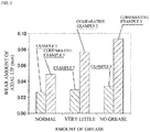
FIG. 3 is a bar graph for comparing wear amounts of axial lips between examples and comparative examples; and -
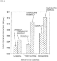
FIG. 4 is a bar graph for comparing wear amounts of radial lips between the examples and the comparative examples. - Next, an embodiment of the present invention will be described in detail based on the accompanying drawings. The present invention is not limited to the embodiment shown in the accompanying drawings and includes all the embodiments satisfying requirements described in the claims.
- In the present description, a direction of a rotating shaft of a radially inner member that is a member on a rotating side when a rotary seal is mounted will be referred to as "axial direction" and a direction orthogonal to the axial direction will be referred to as "radial direction".
- A direction from a vehicle body of an automobile toward a wheel will be referred to as "outward direction" and an opposite direction will be referred to as "inward direction".
- A partial vertical sectional schematic view in
FIG. 1 shows an example in which arotary seal 1 according to the embodiment of the present invention is used for a bearingdevice 11 for supporting a wheel of an automobile. - The
bearing device 11 includes a bearing having aninner ring 12 that has innerring track surfaces 12A on an outer peripheral surface and that rotates with the wheel, anouter ring 13 that has outerring track surfaces 13A on an inner peripheral surface and that is integral with the vehicle body,balls ring track surface 12A and the outerring track surface 13A, and the like. - The
bearing device 11 also includes therotary seals inner ring 12 and the outer ring 13 (on an inner side of theinner balls 14, ... and an outer side of theouter balls 14, ...). - As shown in an enlarged vertical sectional view of a relevant part in
FIG. 2 , each of therotary seals 1 according to the embodiment of the present invention is formed by acore metal 3 manufactured by press working on a stainless steel plate, a seal member 4 that is an elastic body such as rubber having abase portion 4A joined to thecore metal 3 andseal lip portions slinger 2 having sliding contact surfaces A and B with which theseal lip portions - The
slinger 2 is manufactured by press working on a dull-finished ("dull finish" in JIS G 0203:2009 Glossary of terms used in iron and steel) material and uneven surfaces in required surface conditions are formed on the sliding contact surfaces A and B without performing surface machining such as shot peening treatment as in Japanese Patent No.4997532 5234651 - As synthetic rubber material forming the seal member 4, one of the following rubber materials with preferable oil resistance may be used or two or more of them may be properly blended with each other and used: nitrile-butadien rubber (NBR), hydrogenated nitrile-butadien rubber (HNBR), acrylic rubber (ACM), ethylene-acrylic rubber (AEM), fluoro rubber (FKM, FPM), silicone rubber (VQM), and the like. In consideration of ease of kneading, ease of vulcanization, and adhesiveness to the
core metal 3 of the rubber material, it is also preferable to blend the rubber material with other kinds of rubber such as liquid NBR, ethylene-propylene rubber (EPDM), natural rubber (NR), isoprene rubber (IR), styrene-butadiene rubber (SBR), and butadiene rubber (BR). - The
core metal 3 is formed by a cylindricalcore metal cylinder 3A and acore metal flange 3B extending radially inward from one end in an axial direction of thecore metal cylinder 3A and thecore metal 3 and the seal member 4 are fixed to theouter ring 13 by press-fitting thecore metal cylinder 3A into theouter ring 13 that is a radially outer member. - The
slinger 2 is formed by acylindrical sleeve 2A and aflange 2B extending radially outward from one end in the axial direction of thesleeve 2A and theslinger 2 is fixed to theinner ring 12 by press-fitting thesleeve 2A into theinner ring 12 that is a radially inner member. - A tip end of the
seal lip portion 4B that is an axial lip of the seal member 4 comes in sliding contact with the sliding contact surface A of an inner surface of theflange 2B of theslinger 2 and tip ends ofseal lip portions sleeve 2A of theslinger 2. - Each of the sliding contact surfaces A and B of the
slinger 2 manufactured by press working on the dull-finished steel plate material is in such a surface condition that an arithmetic average roughness Ra satisfies 0.3 µm ≤ Ra ≤ 1.0 µm, a skewness of roughness curve Rsk satisfies Rsk ≤ -1, and an average length of roughness curve element RSm satisfies 100 µm ≤ RSm, Ra, Rsk, and RSm defined by JIS B 0601:2013. - Here, the skewness of the roughness curve Rsk represents symmetry of a peak and a valley of roughness. The skewness of the roughness curve Rsk is a positive value when the peak of the roughness is more acute while it is a negative value when the valley of the roughness is more acute.
- The average length of the roughness curve element RSm represents an average length of a contour curve element in a range of a standard length.
- Based on "7. Method and Procedure for Evaluation Using Stylus Surface Roughness Measuring Instrument" in JIS B 0633:2001 (ISO 4288:1996), a roughness curve in a circumferential direction perpendicular to a rolling direction of each of sliding contact surfaces of seal lips of the following examples and comparative examples was measured and an arithmetic average roughness Ra, a skewness of a roughness curve Rsk, and an average length of a roughness curve element RSm were measured with a standard length defined as 0.8 mm and an evaluation length defined as 4 mm and by using a stylus surface roughness measuring instrument (a surface roughness/contour shape measuring instrument manufactured by TOKYO SEIMITSU CO., LTD, model number: SURFCOM1800D).
- A wear amount measurement examination for measuring wear amounts of the seal lips after rotation for 60 hours at a rotation speed of 1000 rpm was conducted for each of rotary seals into which the slingers according to the examples and the comparative examples were mounted and which were filled with different amounts of grease (normal: 0.24 g and very little: 0.005 g) and not filled with grease (no grease).
- In the wear amount measurement examination, the wear amount of the
axial lip 4B inFIG. 2 and the wear amount of theradial lip 4C inFIG. 2 were measured. - Three test specimens which were the slingers formed by press working on the dull-finished steel plates were used as Examples 1 to 3.
- Three test specimens which were the slingers formed by press working on the dull-finished steel plates and shot blasting treatment on the sliding contact surfaces were used as Comparative Examples 1 to 3.
- Experimental Results are shown in Table 1 and
FIGS. 3 and4 . - Roughness parameters Ra, Rsk, and Rsm in each of Examples 1 to 3 and Comparative Examples 1 to 3 are as shown in Table 1.
- The arithmetic average roughness Ra in each of Examples 1 to 3 and Comparative Examples 1 to 3 is about 0.4 µm to 0.5 µm and in a range of 0.3 µm ≤ Ra ≤1.0 µm.
- This is because the arithmetic average roughness Ra of the sliding contact surface needs to be 0.3 µm or greater in order to retain the grease and needs to be 1.0 µm or smaller in order to secure sealing performance at an initial stage of use of the seal.
- The skewness of the roughness curve Rsk of each of Examples 1 to 3 and Comparative Examples 1 to 3 is a negative value. However, the skewness of the roughness curve Rsk of each of Examples 1 to 3 is smaller than -1.1 while Rsk of each of Comparative Examples 1 to 3 having rough surfaces finely formed by the shot blasting treatment is greater than -0.8.
- Here, when the skewness of the roughness curve Rsk is the negative value, tip ends of peak portions protruding from an outer surface of the slinger are obtuse and gentle. The smaller the skewness of the roughness curve Rsk which is the negative value, the gentler the peak portions protruding from the outer surface of the slinger become.
- The more acute the tip ends of the peak portions protruding from the outer surface of the slinger, the more likely plowing wear of rubber becomes to develop. The more obtuse the tip ends of the peak portions, the less likely the plowing wear of rubber becomes to develop. Therefore, the skewness of the roughness curve Rsk is the best preferably smaller than -1.1 and preferably equal to or smaller than -1 as in Examples 1 to 3 for the purpose of further reducing wear amounts of the lips.
- The average length of the roughness curve element RSm in each of Examples 1 to 3 is equal to or longer than 100 µm while RSm in each of Comparative Examples 1 to 3 is shorter than 100 µm.
- In each of the examples, the average length of the roughness curve element RSm is equal to or longer than 100 µm which is longer than in each of the comparative examples and therefore a pitch of repetition of the peak and the valley in the roughness curve is larger. In this way, the number of vibrations (chances of wear) per rotation reduces, which greatly reduces the wear amounts of the lips.
[Table 1] Examples/ Comparative Examples Example 1 Example 2 Example 3 Comparative Example 1 Comparative Example 2 Comparative Example 3 Slinger formed by press working on dull-finished material Slinger in left column with lip sliding contact surfaces subjected to shot blasting treatment Roughness parameters Ra(µm) 0.511 0.542 0.443 0.406 0.503 0.439 Rsk -1.183 -1.253 -1.567 -0.352 -0.619 -0.798 RSm (µm) 114.4 104.7 115.1 30.5 47.8 34.0 Amount of grease Normal Very little No grease Normal Very little No grease Wear amount of axial lip (mm) 0.027 0.030 0.034 0.049 0.077 0.093 Wear amount of radial lip (mm) 0.027 0.032 0.069 0.046 0.106 0.122 - As a result of the above-described differences in the roughness parameters between Examples 1 to 3 and Comparative Examples 1 to 3, as shown in Table 1 and
FIG. 3 , the wear amount of the axial lip in Example 1 is about 55% of that in Comparative Example 1, the wear amount of the axial lip in Example 2 is about 39% of that in Comparative Example 2, and the wear amount of the axial lip in Example 3 is about 37% of that in Comparative Example 3. - Moreover, as shown in Table 1 and
FIG. 4 , the wear amount of the radial lip in Example 1 is about 59% of that in Comparative Example 1, the wear amount of the radial lip in Example 2 is about 30% of that in Comparative Example 2, and the wear amount of the radial lip in Example 3 is about 57% of that in Comparative Example 3. - Therefore, in all of the cases in which the amount of grease is normal and very little and the case without grease, it can be seen that the wear amounts in the examples greatly reduced to about 1/2 to 1/3 those in the comparative examples.
- By this effect, it is possible to suppress the wear of the lips even when the grease dries out due to long-term use.
- According to the rotary seal in the present invention, each of the sliding contact surfaces A and B of the
slinger 2 is in such a surface condition that the arithmetic average roughness Ra satisfies 0.3 µm ≤ Ra ≤ 1.0 µm, the skewness of roughness curve Rsk satisfies Rsk ≤ -1, and the average length of roughness curve element RSm satisfies 100 µm ≤ RSm, Ra, Rsk, and RSm defined by JIS B 0601:2013.Therefore, it is possible to greatly reduce the wear amounts of the seal lip portions to thereby increase reliability as compared with the sliding contact surfaces on which the uneven surfaces are formed by the surface machining such as the shot peening treatment as in Japanese Patent No.4997532 5234651 - Furthermore, even when the grease dries out due to long-term use, the wear of the lips can be suppressed and therefore it is possible to provide the rotary seal with higher reliability.
- Because the
slinger 2 is manufactured by press working on the dull-finished steel plate material, it is possible to reduce manufacturing cost as compared with the sliding contact surfaces on which the uneven surfaces are formed by the surface machining such as the shot peening treatment as in Japanese Patent No.4997532 5234651
Claims (4)
- A rotary seal comprising:a core metal;a seal member having a base portion joined to the core metal and a seal lip portion; anda slinger having at least one sliding contact surface with which the seal lip portion comes in contact,whereinthe at least one sliding contact surface has a surface condition thatan arithmetic average roughness Ra satisfies 0.3 µm ≤ Ra ≤ 1.0 µm,a skewness of roughness curve Rsk satisfies Rsk ≤ -1, andan average length of roughness curve element RSm satisfies 100 µm ≤ RSm, Ra, Rsk, and RSm defined by JIS B 0601:2013.
- The rotary seal according to claim 1, wherein
the core metal is formed by a cylindrical core metal cylinder and a core metal flange extending radially inward from one end in an axial direction of the core metal cylinder,
the slinger is formed by a cylindrical sleeve and a flange extending radially outward from one end in the axial direction of the sleeve,
the at least one sliding contact surface includes a first sliding contact surface and a second sliding contact surface, and
the seal lip portion of the seal member has an axial lip that comes in sliding contact with the first sliding contact surface on an inner surface of the flange of the slinger and a radial lip that comes in sliding contact with the second sliding contact surface of an outer peripheral surface of the sleeve of the slinger. - The rotary seal according to claim 1, wherein the slinger is manufactured by press working on a dull-finished steel plate material.
- The rotary seal according to claim 2, wherein the slinger is manufactured by press working on a dull-finished steel plate material.
Applications Claiming Priority (1)
| Application Number | Priority Date | Filing Date | Title |
|---|---|---|---|
| JP2017045678A JP6874431B2 (en) | 2017-03-10 | 2017-03-10 | Rotating seal |
Publications (2)
| Publication Number | Publication Date |
|---|---|
| EP3372874A1 true EP3372874A1 (en) | 2018-09-12 |
| EP3372874B1 EP3372874B1 (en) | 2020-05-13 |
Family
ID=61557176
Family Applications (1)
| Application Number | Title | Priority Date | Filing Date |
|---|---|---|---|
| EP18159693.3A Active EP3372874B1 (en) | 2017-03-10 | 2018-03-02 | Rotary seal |
Country Status (4)
| Country | Link |
|---|---|
| US (1) | US10605308B2 (en) |
| EP (1) | EP3372874B1 (en) |
| JP (1) | JP6874431B2 (en) |
| CN (1) | CN108571522A (en) |
Families Citing this family (4)
| Publication number | Priority date | Publication date | Assignee | Title |
|---|---|---|---|---|
| JP2020122492A (en) * | 2019-01-29 | 2020-08-13 | 中西金属工業株式会社 | Manufacturing method of slinger for use in rotation seal and rotation seal |
| CN113931934A (en) * | 2021-11-25 | 2022-01-14 | 湖北新火炬科技有限公司 | Hub bearing unit with low-torque sealing structure |
| JP7135224B1 (en) * | 2022-01-12 | 2022-09-12 | Nok株式会社 | Hub seal manufacturing method |
| JP2025020953A (en) * | 2023-07-31 | 2025-02-13 | Ntn株式会社 | Conductively sealed rolling bearings |
Citations (4)
| Publication number | Priority date | Publication date | Assignee | Title |
|---|---|---|---|---|
| JPS5234651B2 (en) | 1974-04-08 | 1977-09-05 | ||
| JP2003184897A (en) * | 2001-12-18 | 2003-07-03 | Nsk Ltd | Sealing device |
| WO2010013439A1 (en) * | 2008-07-30 | 2010-02-04 | Ntn株式会社 | Wheel-bearing device |
| JP4997532B2 (en) | 2004-12-16 | 2012-08-08 | 内山工業株式会社 | Rotating member seal structure |
Family Cites Families (7)
| Publication number | Priority date | Publication date | Assignee | Title |
|---|---|---|---|---|
| JP4665905B2 (en) * | 2005-01-18 | 2011-04-06 | 日本精工株式会社 | Method for manufacturing rolling device |
| JP2007024295A (en) * | 2005-07-21 | 2007-02-01 | Ntn Corp | Cage for rolling bearing, and rolling bearing |
| JP5623010B2 (en) * | 2008-07-30 | 2014-11-12 | Ntn株式会社 | Constant velocity universal joint |
| JP5234651B2 (en) | 2008-08-29 | 2013-07-10 | 内山工業株式会社 | Sealing device |
| JP2014095469A (en) * | 2012-10-09 | 2014-05-22 | Nsk Ltd | Rolling bearing |
| JP2016050674A (en) * | 2014-08-28 | 2016-04-11 | 中西金属工業株式会社 | Protective cover and bearing device provided with protective cover |
| JP2016148420A (en) * | 2015-02-13 | 2016-08-18 | 内山工業株式会社 | Manufacturing method for rotation detection member of sealing device |
-
2017
- 2017-03-10 JP JP2017045678A patent/JP6874431B2/en active Active
-
2018
- 2018-01-18 CN CN201810047574.2A patent/CN108571522A/en active Pending
- 2018-02-28 US US15/907,553 patent/US10605308B2/en active Active
- 2018-03-02 EP EP18159693.3A patent/EP3372874B1/en active Active
Patent Citations (4)
| Publication number | Priority date | Publication date | Assignee | Title |
|---|---|---|---|---|
| JPS5234651B2 (en) | 1974-04-08 | 1977-09-05 | ||
| JP2003184897A (en) * | 2001-12-18 | 2003-07-03 | Nsk Ltd | Sealing device |
| JP4997532B2 (en) | 2004-12-16 | 2012-08-08 | 内山工業株式会社 | Rotating member seal structure |
| WO2010013439A1 (en) * | 2008-07-30 | 2010-02-04 | Ntn株式会社 | Wheel-bearing device |
Also Published As
| Publication number | Publication date |
|---|---|
| US10605308B2 (en) | 2020-03-31 |
| CN108571522A (en) | 2018-09-25 |
| US20180258996A1 (en) | 2018-09-13 |
| EP3372874B1 (en) | 2020-05-13 |
| JP2018150954A (en) | 2018-09-27 |
| JP6874431B2 (en) | 2021-05-19 |
Similar Documents
| Publication | Publication Date | Title |
|---|---|---|
| EP3372874B1 (en) | Rotary seal | |
| US8567789B2 (en) | Sealing device | |
| EP2187074B1 (en) | Method of manufacture of a rolling bearing | |
| US8905645B2 (en) | Wheel bearing apparatus | |
| US20150028663A1 (en) | Seal device for a wheel bearing | |
| JP2003314700A (en) | sticker | |
| CN102654163A (en) | Rolling bearing, throttle valve device and abs device | |
| EP3689488B1 (en) | Manufacturing method for slinger used in rotary seal | |
| EP3587867A1 (en) | Rotary seal | |
| US11215284B2 (en) | Sealing apparatus | |
| JP2004263738A (en) | Sealing device | |
| EP2312176B1 (en) | Sealed rolling bearing | |
| CN109340264A (en) | Double row tapered bearing T-seal structure | |
| JP2007002912A (en) | Rolling bearing | |
| CN107107660B (en) | Wheel bearing device | |
| JP4762576B2 (en) | Mud-water resistant rolling bearing | |
| US7497630B2 (en) | Sealed rolling bearing | |
| CN2888198Y (en) | Skeleton oil seal | |
| JP7051443B2 (en) | Sealing device | |
| CN210178766U (en) | Sealed rolling bearing for tension pulley | |
| EP4425005A1 (en) | Seal member for rolling bearing | |
| JP7835371B2 (en) | Contact seal | |
| JP2024038948A (en) | Bearing sealing device and vehicular bearing device | |
| CN115143191A (en) | Waterproof and oilproof sealed bearing | |
| JP2003113847A (en) | Rolling bearing seal |
Legal Events
| Date | Code | Title | Description |
|---|---|---|---|
| PUAI | Public reference made under article 153(3) epc to a published international application that has entered the european phase |
Free format text: ORIGINAL CODE: 0009012 |
|
| STAA | Information on the status of an ep patent application or granted ep patent |
Free format text: STATUS: THE APPLICATION HAS BEEN PUBLISHED |
|
| AK | Designated contracting states |
Kind code of ref document: A1 Designated state(s): AL AT BE BG CH CY CZ DE DK EE ES FI FR GB GR HR HU IE IS IT LI LT LU LV MC MK MT NL NO PL PT RO RS SE SI SK SM TR |
|
| AX | Request for extension of the european patent |
Extension state: BA ME |
|
| STAA | Information on the status of an ep patent application or granted ep patent |
Free format text: STATUS: REQUEST FOR EXAMINATION WAS MADE |
|
| 17P | Request for examination filed |
Effective date: 20190312 |
|
| RBV | Designated contracting states (corrected) |
Designated state(s): AL AT BE BG CH CY CZ DE DK EE ES FI FR GB GR HR HU IE IS IT LI LT LU LV MC MK MT NL NO PL PT RO RS SE SI SK SM TR |
|
| GRAP | Despatch of communication of intention to grant a patent |
Free format text: ORIGINAL CODE: EPIDOSNIGR1 |
|
| STAA | Information on the status of an ep patent application or granted ep patent |
Free format text: STATUS: GRANT OF PATENT IS INTENDED |
|
| RIC1 | Information provided on ipc code assigned before grant |
Ipc: F16J 15/3256 20160101ALI20190912BHEP Ipc: F16J 15/3264 20160101ALI20190912BHEP Ipc: B60B 27/00 20060101ALI20190912BHEP Ipc: F16J 15/3232 20160101AFI20190912BHEP Ipc: F16C 33/78 20060101ALI20190912BHEP Ipc: F16C 19/18 20060101ALI20190912BHEP |
|
| INTG | Intention to grant announced |
Effective date: 20191004 |
|
| RAP1 | Party data changed (applicant data changed or rights of an application transferred) |
Owner name: NAKANISHI METAL WORKS CO., LTD |
|
| GRAS | Grant fee paid |
Free format text: ORIGINAL CODE: EPIDOSNIGR3 |
|
| RIN1 | Information on inventor provided before grant (corrected) |
Inventor name: IIZAWA, YUSUKE Inventor name: SATO, TAKAHIKO Inventor name: AKASHI, SHINICHI |
|
| RIN1 | Information on inventor provided before grant (corrected) |
Inventor name: AKASHI, SHINICHI Inventor name: IIZAWA, YUSUKE Inventor name: SATO, TAKAHIKO |
|
| RIN1 | Information on inventor provided before grant (corrected) |
Inventor name: SATO, TAKAHIKO Inventor name: AKASHI, SHINICHI Inventor name: IIZAWA, YUSUKE |
|
| GRAA | (expected) grant |
Free format text: ORIGINAL CODE: 0009210 |
|
| STAA | Information on the status of an ep patent application or granted ep patent |
Free format text: STATUS: THE PATENT HAS BEEN GRANTED |
|
| AK | Designated contracting states |
Kind code of ref document: B1 Designated state(s): AL AT BE BG CH CY CZ DE DK EE ES FI FR GB GR HR HU IE IS IT LI LT LU LV MC MK MT NL NO PL PT RO RS SE SI SK SM TR |
|
| REG | Reference to a national code |
Ref country code: GB Ref legal event code: FG4D |
|
| REG | Reference to a national code |
Ref country code: CH Ref legal event code: EP |
|
| REG | Reference to a national code |
Ref country code: DE Ref legal event code: R096 Ref document number: 602018004300 Country of ref document: DE |
|
| REG | Reference to a national code |
Ref country code: AT Ref legal event code: REF Ref document number: 1270717 Country of ref document: AT Kind code of ref document: T Effective date: 20200615 |
|
| REG | Reference to a national code |
Ref country code: LT Ref legal event code: MG4D |
|
| REG | Reference to a national code |
Ref country code: NL Ref legal event code: MP Effective date: 20200513 |
|
| PG25 | Lapsed in a contracting state [announced via postgrant information from national office to epo] |
Ref country code: LT Free format text: LAPSE BECAUSE OF FAILURE TO SUBMIT A TRANSLATION OF THE DESCRIPTION OR TO PAY THE FEE WITHIN THE PRESCRIBED TIME-LIMIT Effective date: 20200513 Ref country code: GR Free format text: LAPSE BECAUSE OF FAILURE TO SUBMIT A TRANSLATION OF THE DESCRIPTION OR TO PAY THE FEE WITHIN THE PRESCRIBED TIME-LIMIT Effective date: 20200814 Ref country code: SE Free format text: LAPSE BECAUSE OF FAILURE TO SUBMIT A TRANSLATION OF THE DESCRIPTION OR TO PAY THE FEE WITHIN THE PRESCRIBED TIME-LIMIT Effective date: 20200513 Ref country code: NO Free format text: LAPSE BECAUSE OF FAILURE TO SUBMIT A TRANSLATION OF THE DESCRIPTION OR TO PAY THE FEE WITHIN THE PRESCRIBED TIME-LIMIT Effective date: 20200813 Ref country code: IS Free format text: LAPSE BECAUSE OF FAILURE TO SUBMIT A TRANSLATION OF THE DESCRIPTION OR TO PAY THE FEE WITHIN THE PRESCRIBED TIME-LIMIT Effective date: 20200913 Ref country code: FI Free format text: LAPSE BECAUSE OF FAILURE TO SUBMIT A TRANSLATION OF THE DESCRIPTION OR TO PAY THE FEE WITHIN THE PRESCRIBED TIME-LIMIT Effective date: 20200513 Ref country code: PT Free format text: LAPSE BECAUSE OF FAILURE TO SUBMIT A TRANSLATION OF THE DESCRIPTION OR TO PAY THE FEE WITHIN THE PRESCRIBED TIME-LIMIT Effective date: 20200914 |
|
| PG25 | Lapsed in a contracting state [announced via postgrant information from national office to epo] |
Ref country code: RS Free format text: LAPSE BECAUSE OF FAILURE TO SUBMIT A TRANSLATION OF THE DESCRIPTION OR TO PAY THE FEE WITHIN THE PRESCRIBED TIME-LIMIT Effective date: 20200513 Ref country code: HR Free format text: LAPSE BECAUSE OF FAILURE TO SUBMIT A TRANSLATION OF THE DESCRIPTION OR TO PAY THE FEE WITHIN THE PRESCRIBED TIME-LIMIT Effective date: 20200513 Ref country code: LV Free format text: LAPSE BECAUSE OF FAILURE TO SUBMIT A TRANSLATION OF THE DESCRIPTION OR TO PAY THE FEE WITHIN THE PRESCRIBED TIME-LIMIT Effective date: 20200513 Ref country code: BG Free format text: LAPSE BECAUSE OF FAILURE TO SUBMIT A TRANSLATION OF THE DESCRIPTION OR TO PAY THE FEE WITHIN THE PRESCRIBED TIME-LIMIT Effective date: 20200813 |
|
| REG | Reference to a national code |
Ref country code: AT Ref legal event code: MK05 Ref document number: 1270717 Country of ref document: AT Kind code of ref document: T Effective date: 20200513 |
|
| PG25 | Lapsed in a contracting state [announced via postgrant information from national office to epo] |
Ref country code: AL Free format text: LAPSE BECAUSE OF FAILURE TO SUBMIT A TRANSLATION OF THE DESCRIPTION OR TO PAY THE FEE WITHIN THE PRESCRIBED TIME-LIMIT Effective date: 20200513 Ref country code: NL Free format text: LAPSE BECAUSE OF FAILURE TO SUBMIT A TRANSLATION OF THE DESCRIPTION OR TO PAY THE FEE WITHIN THE PRESCRIBED TIME-LIMIT Effective date: 20200513 |
|
| PG25 | Lapsed in a contracting state [announced via postgrant information from national office to epo] |
Ref country code: CZ Free format text: LAPSE BECAUSE OF FAILURE TO SUBMIT A TRANSLATION OF THE DESCRIPTION OR TO PAY THE FEE WITHIN THE PRESCRIBED TIME-LIMIT Effective date: 20200513 Ref country code: RO Free format text: LAPSE BECAUSE OF FAILURE TO SUBMIT A TRANSLATION OF THE DESCRIPTION OR TO PAY THE FEE WITHIN THE PRESCRIBED TIME-LIMIT Effective date: 20200513 Ref country code: ES Free format text: LAPSE BECAUSE OF FAILURE TO SUBMIT A TRANSLATION OF THE DESCRIPTION OR TO PAY THE FEE WITHIN THE PRESCRIBED TIME-LIMIT Effective date: 20200513 Ref country code: EE Free format text: LAPSE BECAUSE OF FAILURE TO SUBMIT A TRANSLATION OF THE DESCRIPTION OR TO PAY THE FEE WITHIN THE PRESCRIBED TIME-LIMIT Effective date: 20200513 Ref country code: DK Free format text: LAPSE BECAUSE OF FAILURE TO SUBMIT A TRANSLATION OF THE DESCRIPTION OR TO PAY THE FEE WITHIN THE PRESCRIBED TIME-LIMIT Effective date: 20200513 Ref country code: AT Free format text: LAPSE BECAUSE OF FAILURE TO SUBMIT A TRANSLATION OF THE DESCRIPTION OR TO PAY THE FEE WITHIN THE PRESCRIBED TIME-LIMIT Effective date: 20200513 Ref country code: SM Free format text: LAPSE BECAUSE OF FAILURE TO SUBMIT A TRANSLATION OF THE DESCRIPTION OR TO PAY THE FEE WITHIN THE PRESCRIBED TIME-LIMIT Effective date: 20200513 |
|
| REG | Reference to a national code |
Ref country code: DE Ref legal event code: R097 Ref document number: 602018004300 Country of ref document: DE |
|
| PG25 | Lapsed in a contracting state [announced via postgrant information from national office to epo] |
Ref country code: PL Free format text: LAPSE BECAUSE OF FAILURE TO SUBMIT A TRANSLATION OF THE DESCRIPTION OR TO PAY THE FEE WITHIN THE PRESCRIBED TIME-LIMIT Effective date: 20200513 Ref country code: SK Free format text: LAPSE BECAUSE OF FAILURE TO SUBMIT A TRANSLATION OF THE DESCRIPTION OR TO PAY THE FEE WITHIN THE PRESCRIBED TIME-LIMIT Effective date: 20200513 |
|
| PLBE | No opposition filed within time limit |
Free format text: ORIGINAL CODE: 0009261 |
|
| STAA | Information on the status of an ep patent application or granted ep patent |
Free format text: STATUS: NO OPPOSITION FILED WITHIN TIME LIMIT |
|
| 26N | No opposition filed |
Effective date: 20210216 |
|
| PG25 | Lapsed in a contracting state [announced via postgrant information from national office to epo] |
Ref country code: SI Free format text: LAPSE BECAUSE OF FAILURE TO SUBMIT A TRANSLATION OF THE DESCRIPTION OR TO PAY THE FEE WITHIN THE PRESCRIBED TIME-LIMIT Effective date: 20200513 |
|
| PG25 | Lapsed in a contracting state [announced via postgrant information from national office to epo] |
Ref country code: MC Free format text: LAPSE BECAUSE OF FAILURE TO SUBMIT A TRANSLATION OF THE DESCRIPTION OR TO PAY THE FEE WITHIN THE PRESCRIBED TIME-LIMIT Effective date: 20200513 |
|
| REG | Reference to a national code |
Ref country code: CH Ref legal event code: PL |
|
| REG | Reference to a national code |
Ref country code: BE Ref legal event code: MM Effective date: 20210331 |
|
| PG25 | Lapsed in a contracting state [announced via postgrant information from national office to epo] |
Ref country code: LI Free format text: LAPSE BECAUSE OF NON-PAYMENT OF DUE FEES Effective date: 20210331 Ref country code: LU Free format text: LAPSE BECAUSE OF NON-PAYMENT OF DUE FEES Effective date: 20210302 Ref country code: CH Free format text: LAPSE BECAUSE OF NON-PAYMENT OF DUE FEES Effective date: 20210331 Ref country code: IE Free format text: LAPSE BECAUSE OF NON-PAYMENT OF DUE FEES Effective date: 20210302 |
|
| PG25 | Lapsed in a contracting state [announced via postgrant information from national office to epo] |
Ref country code: BE Free format text: LAPSE BECAUSE OF NON-PAYMENT OF DUE FEES Effective date: 20210331 |
|
| GBPC | Gb: european patent ceased through non-payment of renewal fee |
Effective date: 20220302 |
|
| PG25 | Lapsed in a contracting state [announced via postgrant information from national office to epo] |
Ref country code: GB Free format text: LAPSE BECAUSE OF NON-PAYMENT OF DUE FEES Effective date: 20220302 |
|
| PG25 | Lapsed in a contracting state [announced via postgrant information from national office to epo] |
Ref country code: CY Free format text: LAPSE BECAUSE OF FAILURE TO SUBMIT A TRANSLATION OF THE DESCRIPTION OR TO PAY THE FEE WITHIN THE PRESCRIBED TIME-LIMIT Effective date: 20200513 |
|
| PG25 | Lapsed in a contracting state [announced via postgrant information from national office to epo] |
Ref country code: HU Free format text: LAPSE BECAUSE OF FAILURE TO SUBMIT A TRANSLATION OF THE DESCRIPTION OR TO PAY THE FEE WITHIN THE PRESCRIBED TIME-LIMIT; INVALID AB INITIO Effective date: 20180302 |
|
| PG25 | Lapsed in a contracting state [announced via postgrant information from national office to epo] |
Ref country code: MK Free format text: LAPSE BECAUSE OF FAILURE TO SUBMIT A TRANSLATION OF THE DESCRIPTION OR TO PAY THE FEE WITHIN THE PRESCRIBED TIME-LIMIT Effective date: 20200513 |
|
| PG25 | Lapsed in a contracting state [announced via postgrant information from national office to epo] |
Ref country code: TR Free format text: LAPSE BECAUSE OF FAILURE TO SUBMIT A TRANSLATION OF THE DESCRIPTION OR TO PAY THE FEE WITHIN THE PRESCRIBED TIME-LIMIT Effective date: 20200513 |
|
| PG25 | Lapsed in a contracting state [announced via postgrant information from national office to epo] |
Ref country code: MT Free format text: LAPSE BECAUSE OF FAILURE TO SUBMIT A TRANSLATION OF THE DESCRIPTION OR TO PAY THE FEE WITHIN THE PRESCRIBED TIME-LIMIT Effective date: 20200513 |
|
| PGFP | Annual fee paid to national office [announced via postgrant information from national office to epo] |
Ref country code: DE Payment date: 20250331 Year of fee payment: 8 |
|
| PGFP | Annual fee paid to national office [announced via postgrant information from national office to epo] |
Ref country code: IT Payment date: 20250331 Year of fee payment: 8 |
|
| PGFP | Annual fee paid to national office [announced via postgrant information from national office to epo] |
Ref country code: FR Payment date: 20260324 Year of fee payment: 9 |