EP3372813A1 - Multi degree of freedom flutter damper - Google Patents
Multi degree of freedom flutter damper Download PDFInfo
- Publication number
- EP3372813A1 EP3372813A1 EP18160541.1A EP18160541A EP3372813A1 EP 3372813 A1 EP3372813 A1 EP 3372813A1 EP 18160541 A EP18160541 A EP 18160541A EP 3372813 A1 EP3372813 A1 EP 3372813A1
- Authority
- EP
- European Patent Office
- Prior art keywords
- flutter
- modular chambers
- chambers
- fan
- modular
- Prior art date
- Legal status (The legal status is an assumption and is not a legal conclusion. Google has not performed a legal analysis and makes no representation as to the accuracy of the status listed.)
- Granted
Links
Images


Classifications
-
- F—MECHANICAL ENGINEERING; LIGHTING; HEATING; WEAPONS; BLASTING
- F02—COMBUSTION ENGINES; HOT-GAS OR COMBUSTION-PRODUCT ENGINE PLANTS
- F02C—GAS-TURBINE PLANTS; AIR INTAKES FOR JET-PROPULSION PLANTS; CONTROLLING FUEL SUPPLY IN AIR-BREATHING JET-PROPULSION PLANTS
- F02C7/00—Features, components parts, details or accessories, not provided for in, or of interest apart form groups F02C1/00 - F02C6/00; Air intakes for jet-propulsion plants
- F02C7/04—Air intakes for gas-turbine plants or jet-propulsion plants
- F02C7/045—Air intakes for gas-turbine plants or jet-propulsion plants having provisions for noise suppression
-
- F—MECHANICAL ENGINEERING; LIGHTING; HEATING; WEAPONS; BLASTING
- F02—COMBUSTION ENGINES; HOT-GAS OR COMBUSTION-PRODUCT ENGINE PLANTS
- F02K—JET-PROPULSION PLANTS
- F02K1/00—Plants characterised by the form or arrangement of the jet pipe or nozzle; Jet pipes or nozzles peculiar thereto
- F02K1/78—Other construction of jet pipes
- F02K1/82—Jet pipe walls, e.g. liners
- F02K1/827—Sound absorbing structures or liners
-
- F—MECHANICAL ENGINEERING; LIGHTING; HEATING; WEAPONS; BLASTING
- F05—INDEXING SCHEMES RELATING TO ENGINES OR PUMPS IN VARIOUS SUBCLASSES OF CLASSES F01-F04
- F05D—INDEXING SCHEME FOR ASPECTS RELATING TO NON-POSITIVE-DISPLACEMENT MACHINES OR ENGINES, GAS-TURBINES OR JET-PROPULSION PLANTS
- F05D2260/00—Function
- F05D2260/96—Preventing, counteracting or reducing vibration or noise
-
- Y—GENERAL TAGGING OF NEW TECHNOLOGICAL DEVELOPMENTS; GENERAL TAGGING OF CROSS-SECTIONAL TECHNOLOGIES SPANNING OVER SEVERAL SECTIONS OF THE IPC; TECHNICAL SUBJECTS COVERED BY FORMER USPC CROSS-REFERENCE ART COLLECTIONS [XRACs] AND DIGESTS
- Y02—TECHNOLOGIES OR APPLICATIONS FOR MITIGATION OR ADAPTATION AGAINST CLIMATE CHANGE
- Y02T—CLIMATE CHANGE MITIGATION TECHNOLOGIES RELATED TO TRANSPORTATION
- Y02T50/00—Aeronautics or air transport
- Y02T50/60—Efficient propulsion technologies, e.g. for aircraft
Definitions
- Exemplary embodiments pertain to flutter dampers in gas turbine propulsion systems and, more particularly, to flutter dampers in nacelle inlet structures.
- Geared turbofan architectures allow for high bypass ratio turbofans, enabling the use of low pressure ratio fans, which may be more susceptible to fan flutter than high pressure ratio fans.
- Fan flutter is an aeromechanical instability detrimental to the life of a fan blade.
- a flutter damper which, by absorbing the acoustic energy associated with the flutter structural mode, may prevent the fan from fluttering, and which may be integrated into the reduced available space in an optimized propulsion system.
- a flutter damper including an acoustic liner in fluid communication with a fluid flow, the acoustic liner being configured for peak acoustical energy absorption at a frequency range that is greater than a frequency range associated with fan flutter, and a plurality of modular chambers, each of the plurality of modular chambers being configured for peak acoustical energy absorption at a frequency range that is associated with one or more fan flutter modes, and the plurality of modular chambers being disposed radially outside of the acoustic liner, and the plurality of modular chambers including a circumferential gap between proximate circumferential ends of at least one adjacent pair of modular chambers, wherein, the plurality of modular chambers each include a plurality of circumferentially aligned and connected chamber segments.
- further embodiments may include that circumferentially adjacent chamber segments in each of the modular chambers are acoustically insulated.
- further embodiments may include that at least two of the plurality of modular chambers are configured for peak acoustical energy absorption at a frequency range that is associated with mutually distinct fan flutter modes.
- further embodiments may include a plurality of circumferential gaps respectively disposed between each pair of proximate circumferential ends of the modular chambers.
- further embodiments may include that circumferential ends of the modular chambers are beveled.
- further embodiments may include a cover sheet disposed on the acoustic liner perforated only in areas between the acoustic liner and the plurality of modular chambers.
- further embodiments may include that the chamber segments are box or rectangular shaped.
- further embodiments may include that the chamber segments not box shape (e.g., may be elliptically shaped).
- each of the box or elliptical shaped chambers may have a different external dimension while maintaining a desired volume.
- the modular chambers are a metallic material, including aluminum, or a plastic or a composite, or a hybrid metallic and non-metallic material.
- a method of providing flutter damping in a gas turbine engine including absorbing acoustic energy with an acoustic liner configured for peak acoustical energy absorption at a frequency range that is greater than a frequency range associated with fan flutter, and absorbing acoustic energy with a plurality of modular chambers, each of the plurality of modular chambers being configured for peak acoustical energy absorption at a frequency range that is associated with one or more fan flutter modes wherein the plurality of modular chambers are disposed radially outside of the acoustic liner and separated by a circumferential gap between proximate circumferential ends of at least one adjacent pair of modular chambers, and wherein the plurality of modular chambers each including a plurality of circumferentially aligned and connected chamber segments.
- the modular chambers may include one or more of the above disclosed features.
- the exemplary engine 20 generally includes a low speed spool 30 and a high speed spool 32 mounted for rotation about an engine central longitudinal axis A relative to an engine static structure 36 via multiple bearing systems 38. It should be understood that various bearing systems 38 at various locations may alternatively or additionally be provided, and the location of bearing systems 38 may be varied as appropriate to the application.
- the low speed spool 30 generally includes an inner shaft 40 that interconnects a fan 42, a low pressure compressor 44 and a low pressure turbine 46.
- the inner shaft 40 is connected to the fan 42 through a speed change mechanism, which in exemplary gas turbine engine 20 is illustrated as a geared architecture 48 to drive the fan 42 at a lower speed than the low speed spool 30.
- the high speed spool 32 includes an outer shaft 50 that interconnects a high pressure compressor 52 and high pressure turbine 54.
- a combustor 56 is arranged in exemplary gas turbine 20 between the high pressure compressor 52 and the high pressure turbine 54.
- An engine static structure 36 is arranged generally between the high pressure turbine 54 and the low pressure turbine 46.
- the engine static structure 36 further supports bearing systems 38 in the turbine section 28.
- the inner shaft 40 and the outer shaft 50 are concentric and rotate via bearing systems 38 about the engine central longitudinal axis A which is collinear with their longitudinal axes.
- each of the positions of the fan section 22, compressor section 24, combustor section 26, turbine section 28, and fan drive gear system 48 may be varied.
- gear system 48 may be located aft of combustor section 26 or even aft of turbine section 28, and fan section 22 may be positioned forward or aft of the location of gear system 48.
- the fan section 22 of the engine 20 is designed for a particular flight condition--typically cruise at about 0.8Mach and about 35,000 feet (10,688 meters).
- 'TSFC' Thrust Specific Fuel Consumption
- Low fan pressure ratio is the pressure ratio across the fan blade alone, without a Fan Exit Guide Vane (“FEGV”) system.
- the low fan pressure ratio as disclosed herein according to one non-limiting embodiment is less than about 1.45.
- Low corrected fan tip speed is the actual fan tip speed in ft/sec divided by an industry standard temperature correction of [(Tram °R)/(518.7 °R)] 0.5 .
- the "Low corrected fan tip speed” as disclosed herein according to one non-limiting embodiment is less than about 1150 ft/second (350.5 m/sec).
- the engine 20 may include a nacelle 100 with acoustic liner 101 at the radial inside of the nacelle inlet skin 106.
- the acoustic liner 101 may have a perforated radial inner face sheet 108, i.e., facing a radial inside of a nacelle inlet 103, illustrated in FIG. 2 , and a radial outer back sheet 110.
- the acoustic liner 101 is designed to absorb energy that tends to produce community noise.
- the acoustic liner 101 typically provides for peak energy absorption in the acoustic frequency range of about between 500 and 2000 Hz, and is less effective outside this range.
- Fan flutter for such propulsion systems typically occurs at a lower frequency, depending on the frequency and nodal diameter count of the critical structural mode.
- the structural frequency largely depends on the size of the fan, among other design parameters. Large fans tend to flutter at smaller frequencies than small fans. Torsion modes tend to have higher frequency than bending modes on any given fan, and either can be critical.
- the materials and construction techniques used to make the fan blades also have a significant influence on the frequency.
- the flutter frequency will typically occur at a frequency range of less than but not equal to 500 Hz, and more specifically between 50 and 400 Hz, yet more specifically between 50 and 300 Hz, and yet more specifically between 50 and 200 Hz.
- variable f S,ND is the frequency, which is measured in units of Hertz, and which corresponds to a resonance frequency of a structural mode of the fan blade, which typically may be a first or second bending mode with a certain nodal diameter count, ND.
- the variable ND is the nodal diameter count of the circumferential pattern of the structural mode of the fan blade.
- the variable ⁇ is the rotational speed of the fan, which is measured in the units of revolutions per second.
- variable ⁇ may be chosen to correspond to conditions where fan flutter may typically occur, for example, when the tip relative Mach number of the fan is between 0.85 and 1.2 during standard-day, sea-level-static operation.
- the disclosed embodiments may provide for improved community noise as a result of less interference with the outer edges of each chamber.
- the disclosed embodiments may also increase fan flutter margin and fan flutter capability.
Landscapes
- Engineering & Computer Science (AREA)
- Chemical & Material Sciences (AREA)
- Combustion & Propulsion (AREA)
- Mechanical Engineering (AREA)
- General Engineering & Computer Science (AREA)
- Structures Of Non-Positive Displacement Pumps (AREA)
Abstract
Description
- Exemplary embodiments pertain to flutter dampers in gas turbine propulsion systems and, more particularly, to flutter dampers in nacelle inlet structures.
- Geared turbofan architectures, allow for high bypass ratio turbofans, enabling the use of low pressure ratio fans, which may be more susceptible to fan flutter than high pressure ratio fans. Fan flutter is an aeromechanical instability detrimental to the life of a fan blade.
- Accordingly, there is a need for a flutter damper which, by absorbing the acoustic energy associated with the flutter structural mode, may prevent the fan from fluttering, and which may be integrated into the reduced available space in an optimized propulsion system.
- Disclosed is a flutter damper, including an acoustic liner in fluid communication with a fluid flow, the acoustic liner being configured for peak acoustical energy absorption at a frequency range that is greater than a frequency range associated with fan flutter, and a plurality of modular chambers, each of the plurality of modular chambers being configured for peak acoustical energy absorption at a frequency range that is associated with one or more fan flutter modes, and the plurality of modular chambers being disposed radially outside of the acoustic liner, and the plurality of modular chambers including a circumferential gap between proximate circumferential ends of at least one adjacent pair of modular chambers, wherein, the plurality of modular chambers each include a plurality of circumferentially aligned and connected chamber segments.
- In addition to one or more of the features described above, or as an alternative, further embodiments may include that circumferentially adjacent chamber segments in each of the modular chambers are acoustically insulated.
- In addition to one or more of the features described above, or as an alternative, further embodiments may include that at least two of the plurality of modular chambers are configured for peak acoustical energy absorption at a frequency range that is associated with mutually distinct fan flutter modes.
- In addition to one or more of the features described above, or as an alternative, further embodiments may include a plurality of circumferential gaps respectively disposed between each pair of proximate circumferential ends of the modular chambers.
- In addition to one or more of the features described above, or as an alternative, further embodiments may include that circumferential ends of the modular chambers are beveled.
- In addition to one or more of the features described above, or as an alternative, further embodiments may include a cover sheet disposed on the acoustic liner perforated only in areas between the acoustic liner and the plurality of modular chambers.
- In addition to one or more of the features described above, or as an alternative, further embodiments may include that the chamber segments are box or rectangular shaped.
- In addition to one or more of the features described above or as an alternative, further embodiments may include that the chamber segments not box shape (e.g., may be elliptically shaped).
- In addition to one or more of the features described above or as an alternative, each of the box or elliptical shaped chambers may have a different external dimension while maintaining a desired volume.
- In addition to one or more of the features described above or as an alternative, the modular chambers are a metallic material, including aluminum, or a plastic or a composite, or a hybrid metallic and non-metallic material.
- Further disclosed is a gas turbine engine system, including a nacelle, and a flutter damper disposed within the nacelle. The flutter damper may include one or more of the above disclosed features.
- Further disclosed is a method of providing flutter damping in a gas turbine engine, including absorbing acoustic energy with an acoustic liner configured for peak acoustical energy absorption at a frequency range that is greater than a frequency range associated with fan flutter, and absorbing acoustic energy with a plurality of modular chambers, each of the plurality of modular chambers being configured for peak acoustical energy absorption at a frequency range that is associated with one or more fan flutter modes wherein the plurality of modular chambers are disposed radially outside of the acoustic liner and separated by a circumferential gap between proximate circumferential ends of at least one adjacent pair of modular chambers, and wherein the plurality of modular chambers each including a plurality of circumferentially aligned and connected chamber segments. The modular chambers may include one or more of the above disclosed features.
- The following descriptions should not be considered limiting in any way. With reference to the accompanying drawings, like elements are numbered alike:
-
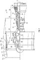
FIG. 1 is a schematic view of a gas turbine propulsion system; -
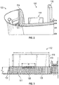
FIG. 2 illustrates a perspective cross sectional view of an exemplary flutter damper in a nacelle inlet; -
FIG. 3 is a schematic view of a flutter damper in accordance with one embodiment of the disclosure; -
FIGS. 4A and 4B illustrate perspective views of one chamber of a flutter damper in accordance with one embodiment of the disclosure; -
FIG. 5 illustrates an array of chambers of flutter dampers integrated into the nacelle inlet; -
FIG. 6 is a perspective view of a portion of the nacelle inlet; -
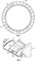
FIGS. 7A, 7B, and 7C each illustrate an array of chambers integrated into the nacelle inlet according to one embodiment of the disclosure; -
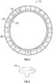
FIG. 8 illustrates an array of chambers integrated into the nacelle inlet according to one embodiment of the disclosure; and -
FIG. 9 illustrates a chamber according to one embodiment of the disclosure. - A detailed description of one or more embodiments of the disclosed apparatus and method are presented herein by way of exemplification and not limitation with reference to the Figures.
-
FIG. 1 schematically illustrates agas turbine engine 20. Thegas turbine engine 20 is disclosed herein as a two-spool turbofan that generally incorporates afan section 22, acompressor section 24, acombustor section 26 and aturbine section 28. Alternative engines might include an augmentor section (not shown) among other systems or features. Thefan section 22 drives air along a bypass flow path B in a bypass duct, while thecompressor section 24 drives air along a core flow path C for compression and communication into thecombustor section 26 then expansion through theturbine section 28. Although depicted as a two-spool turbofan gas turbine engine in the disclosed non-limiting embodiment, it should be understood that the concepts described herein are not limited to use with two-spool turbofans as the teachings may be applied to other types of turbine engines including three-spool architectures. - The
exemplary engine 20 generally includes alow speed spool 30 and ahigh speed spool 32 mounted for rotation about an engine central longitudinal axis A relative to an enginestatic structure 36 viamultiple bearing systems 38. It should be understood thatvarious bearing systems 38 at various locations may alternatively or additionally be provided, and the location ofbearing systems 38 may be varied as appropriate to the application. - The
low speed spool 30 generally includes aninner shaft 40 that interconnects afan 42, alow pressure compressor 44 and alow pressure turbine 46. Theinner shaft 40 is connected to thefan 42 through a speed change mechanism, which in exemplarygas turbine engine 20 is illustrated as a gearedarchitecture 48 to drive thefan 42 at a lower speed than thelow speed spool 30. Thehigh speed spool 32 includes anouter shaft 50 that interconnects ahigh pressure compressor 52 andhigh pressure turbine 54. Acombustor 56 is arranged inexemplary gas turbine 20 between thehigh pressure compressor 52 and thehigh pressure turbine 54. An enginestatic structure 36 is arranged generally between thehigh pressure turbine 54 and thelow pressure turbine 46. The enginestatic structure 36 further supports bearingsystems 38 in theturbine section 28. Theinner shaft 40 and theouter shaft 50 are concentric and rotate viabearing systems 38 about the engine central longitudinal axis A which is collinear with their longitudinal axes. - The core airflow is compressed by the
low pressure compressor 44 then thehigh pressure compressor 52, mixed and burned with fuel in thecombustor 56, then expanded over thehigh pressure turbine 54 andlow pressure turbine 46. Theturbines low speed spool 30 andhigh speed spool 32 in response to the expansion. It will be appreciated that each of the positions of thefan section 22,compressor section 24,combustor section 26,turbine section 28, and fandrive gear system 48 may be varied. For example,gear system 48 may be located aft ofcombustor section 26 or even aft ofturbine section 28, andfan section 22 may be positioned forward or aft of the location ofgear system 48. - The
engine 20 in one example is a high-bypass geared aircraft engine. In a further example, theengine 20 bypass ratio is greater than about six (6), with an example embodiment being greater than about ten (10), the gearedarchitecture 48 is an epicyclic gear train, such as a planetary gear system or other gear system, with a gear reduction ratio of greater than about 2.3 and thelow pressure turbine 46 has a pressure ratio that is greater than about five. In one disclosed embodiment, theengine 20 bypass ratio is greater than about ten (10:1), the fan diameter is significantly larger than that of thelow pressure compressor 44, and thelow pressure turbine 46 has a pressure ratio that is greater than about five 5:1.Low pressure turbine 46 pressure ratio is pressure measured prior to inlet oflow pressure turbine 46 as related to the pressure at the outlet of thelow pressure turbine 46 prior to an exhaust nozzle. The gearedarchitecture 48 may be an epicycle gear train, such as a planetary gear system or other gear system, with a gear reduction ratio of greater than about 2.3:1. It should be understood, however, that the above parameters are only exemplary of one embodiment of a geared architecture engine and that the present disclosure is applicable to other gas turbine engines including direct drive turbofans. - A significant amount of thrust is provided by the bypass flow B due to the high bypass ratio. The
fan section 22 of theengine 20 is designed for a particular flight condition--typically cruise at about 0.8Mach and about 35,000 feet (10,688 meters). The flight condition of 0.8 Mach and 35,000 ft (10,688 meters), with the engine at its best fuel consumption--also known as "bucket cruise Thrust Specific Fuel Consumption ('TSFC')"--is the industry standard parameter of lbm of fuel being burned divided by lbf of thrust the engine produces at that minimum point. "Low fan pressure ratio" is the pressure ratio across the fan blade alone, without a Fan Exit Guide Vane ("FEGV") system. The low fan pressure ratio as disclosed herein according to one non-limiting embodiment is less than about 1.45. "Low corrected fan tip speed" is the actual fan tip speed in ft/sec divided by an industry standard temperature correction of [(Tram °R)/(518.7 °R)]0.5. The "Low corrected fan tip speed" as disclosed herein according to one non-limiting embodiment is less than about 1150 ft/second (350.5 m/sec). - As illustrated in
FIGS. 1 through 3 , theengine 20 may include anacelle 100 withacoustic liner 101 at the radial inside of thenacelle inlet skin 106. Theacoustic liner 101 may have a perforated radialinner face sheet 108, i.e., facing a radial inside of anacelle inlet 103, illustrated inFIG. 2 , and a radialouter back sheet 110. - The
acoustic liner 101 is designed to absorb energy that tends to produce community noise. As such, for contemporary high bypass ratio propulsion systems, theacoustic liner 101 typically provides for peak energy absorption in the acoustic frequency range of about between 500 and 2000 Hz, and is less effective outside this range. Fan flutter for such propulsion systems, however, typically occurs at a lower frequency, depending on the frequency and nodal diameter count of the critical structural mode. The structural frequency largely depends on the size of the fan, among other design parameters. Large fans tend to flutter at smaller frequencies than small fans. Torsion modes tend to have higher frequency than bending modes on any given fan, and either can be critical. The materials and construction techniques used to make the fan blades also have a significant influence on the frequency. Given the range of sizes, materials, and flutter critical modes in fans of modern gas turbine engines, the flutter frequency will typically occur at a frequency range of less than but not equal to 500 Hz, and more specifically between 50 and 400 Hz, yet more specifically between 50 and 300 Hz, and yet more specifically between 50 and 200 Hz. - In one embodiment, a
flutter damper 102 is provided which may include theacoustic liner 101 and achamber 118 disposed radially exterior to and in acoustic communication with theacoustic liner 101. Also aflutter damper 102 without theacoustic liner 101 is considered part of the scope of this disclosure. As used herein, radially refers to the axis A of theengine 20. Acoustic communication is provided through aperforation section 120 in theouter back sheet 110. InFIG. 2 , theflutter damper 102 is illustrated as being disposed between a first axialforward nacelle bulkhead 114 and a second axialforward nacelle bulkhead 116. Theflutter damper 102, however, may be disposed anywhere between aleading edge 111 of thefan 42 and anacelle hilite 113, such asflutter damper 102A disposed on thefan case 115 illustrated inFIG. 1 . - The
flutter damper 102 may be configured to mitigate fan flutter by providing peak energy absorption in the acoustic frequency range associated with fan flutter modes, where such frequency range is referred to herein as a flutter frequency range. The flutter damper may have desirable impedance characteristics at certain targeted flutter frequencies, which may be defined as:
- In the equation above, the variable fS,ND is the frequency, which is measured in units of Hertz, and which corresponds to a resonance frequency of a structural mode of the fan blade, which typically may be a first or second bending mode with a certain nodal diameter count, ND. The variable ND is the nodal diameter count of the circumferential pattern of the structural mode of the fan blade. The variable Ω is the rotational speed of the fan, which is measured in the units of revolutions per second.
- The values for variable Ω may be chosen to correspond to conditions where fan flutter may typically occur, for example, when the tip relative Mach number of the fan is between 0.85 and 1.2 during standard-day, sea-level-static operation.
- From the above equation, considering the nodal diameter constraints, the targeted flutter frequency ranges may be defined to be:



- In the above equation, Mreltip is the tip relative Mach number for a radial outer tip of the fan blade, and the bending mode is a vibrational mode of the fan blade. The symbol Ω Mreltip=0.85 denotes the rotational speed where the tip relative Mach number is equal to 0.85; likewise, Ω Mreltip=1.2 denotes the rotational speed where the tip relative Mach number is equal to 1.2, Of course, values greater or lesser than the aforementioned values are considered to be within the scope of the present disclosure.
- Within the flutter frequency ranges associated with the first and second bending mode, and more specifically at the targeted frequencies, the flutter damper may have the following impedance characteristics:


- Again, these values may vary and fall within the scope of the present disclosure. The above equation references the impedance of the flutter damper, defined as the complex ratio of the amplitude and phase of pressure oscillations over the amplitude and phase of the acoustic velocity as a function of frequency. In addition, the equation references the real part of impedance is the resistance, which is variable R, and the imaginary part of impedance is the reactance, which is variable X. The variable ρ is the air density, and the variable c is the sound speed, both being at the entrance to the flutter damper. The resistance constraint on R may facilitate integration of the flutter damper into acoustic liners, which typically have R values greater than 2ρc in locations forward of the fan. The reactance constraint on X optimizes the flutter inhibiting capability of the device at operating conditions typically encountered in commercial aircraft applications. At certain target frequencies, the flutter damper may satisfy the following additional constraint:

- Again, these values may vary and fall within the scope of the present disclosure. As illustrated in
FIGS. 3 ,4A and 4B , discussed in greater detail below, thechamber 118 has a width W, a height H, and a length L. In addition, theperforated section 120 disposed under thechamber 118 has a width Wp and a length Lp, and theacoustic liner 101 has a height HLi. Thus, in the above equation, the volume of theflutter damper 102, which includes the volume (W x H x L) ofchamber 118 and the volume (Wp x HLi x Lp) of theacoustic liner 101 is variable V. The area of the perforated section 120 (Wp x Lp) disposed under thechamber 118 is variable S. The units of V, S, c and ftarget are chosen such that
- Moreover, in one embodiment, a downstream edge of the
chamber 118 may be located at B/D ≤ 0.35. In this equation, the variable B is the distance between the downstream edge of thechamber 118 and the fan tip leading edge, and the variable D is the fan tip diameter at the leading edge of the fan blade. - Remaining with
FIGS. 1-3 , the illustratedflutter damper 102 designed according to the above constraints, has the benefit of being able to fit within smaller footprints of sized-optimized propulsion systems, providing a retrofittable solution to an existing engine inlet. Thus the disclosedflutter damper 102 may help boost fan flutter margin without requiring an inlet redesign. In addition, theflutter damper 102 may provide a relatively lightweight solution, that is, the low temperatures of the inlet area may allow for the use of a metallic material, including aluminum, or a plastic or a composite, or a hybrid metallic and non-metallic material. Moreover, theflutter damper 102 may have a scalable design which can be oriented in an array of chambers, discussed in detail, below, and as illustrated in at leastFIG. 5 . For example, the array of chambers and may be placed around an engine inlet circumference to achieve a desired amount of flutter dampening volume. - As illustrated in
FIG. 4A and 4B , theperforation section 120 in theouter back sheet 110 may be rectangular in shape with length Lp and width Wp, where the length direction Lp corresponds to the engine axial direction, and the width direction Wp corresponds to the engine circumferential direction. For a contemporary high bypass ratio propulsion system, which may have a fan diameter of about 80 inches (about 2 metres), and a fan rotor hub-to-tip ratio of about 0.3, the length Lp may be about four and half (4.5) inches (115 mm) for thechamber 118, and the width Wp may be about twelve (12) inches (305 mm) forchamber 118. Eachperforation section 120 may have a hole-diameter of about thirty thousandths (0.030) of an inch (0.76 mm). Of course, dimensions greater or lesser than the aforementioned dimensions, and non-rectangular shapes are considered to be within the scope of the present disclosure. This perforation geometry provides an open area that may be about four and half (4.5) percent of the surface area (Lp x Wp) of thechamber 118 against theouter back sheet 110, which may be the same open area as a perforation section (not illustrated) in theinner face sheet 108. Again, these dimensions may vary and remain within the scope of the present disclosure. - The
chamber 118 may be sized to optimally dampen fan flutter at a specific fan flutter frequency and nodal diameter. The nodal diameter count represents the nodal lines of vibrational modes observed for the fan blade, which typically may be between 1 and 3. Thechamber 118 inFIG. 2 , for example, is shaped as a rectangular box, and non-rectangular shapes are also within the scope of this disclosure, and may be sized based on an observed flutter frequencies and nodal diameters for a given engine. For example, if an engine has an observable flutter mode at a frequency of about 150 Hz with nodal diameter 2, thechamber 118 may be sized according to that flutter mode and nodal diameter. - The box shape, as illustrated in
FIG. 4A , may have atop surface 122 roughly defined by a width-length (W x L) area, where the length direction L corresponds to the engine axial direction, and the width direction W corresponds to the engine circumferential direction. The box shape may also have afront surface 124 and aback surface 125, each roughly defined by a height-width (H x W) area, where the height direction H for thechamber 118 may correspond to an engine radial direction. The box shape may further have aside surface 126 roughly defined by a height-length (H x L) area. Again, these dimensions may vary and remain within the scope of the present disclosure. - For the exemplary embodiment, the
chamber 118 is twelve (12) inches (305 mm) wide, as referenced above, and the chamber width-height-length (W x H x L) volume may be three hundred twenty four (324) cubic inches (5.3 x 10⁻³ m3), and the height H may be equal to, or less than, six (6) inches (152 mm). - Turning now to
FIGS. 4A and 4B , the box shapedchamber 118 may have abottom edge 128 that geometrically conforms to the annular and axial profile shape of thenacelle inlet 103. Extending axially and circumferentially outwardly from thebottom edge 128 of thechamber 118 is a mountingflange 130 for affixing thechamber 118 to an existingnacelle inlet 103. As such, thebottom face 131 of thechamber 118 may be formed by the radialouter back sheet 110 of theacoustic liner 101. - The
chamber 118 may also include first andsecond stiffening structures structures side surface 126 of thechamber 118, which protrudes outwardly from the top 122,front 124 and back 125 surfaces of thechamber 118. The stiffeningstructures top surface 122 of thechamber 118 in substantially equal portions in the width direction W. The stiffeningstructures chamber 118 away from the fan flutter frequencies to avoid fan flutter inducing resonance in thechamber 118. For example, the stiffeningstructures top surface 122 of thechamber 118 out of the targeted flutter frequency range. In addition, the stiffeningstructures chamber 118. - One or more weep
holes 136 may be provided to allow for water or fluid egress. The placement of the weepholes 136 is selected to be below the engine centerline - Turning now to
FIGS. 5 and 6 acircumferential array 138 ofchambers 118, including fourteen (14)chambers 118, is disposed about thenacelle inlet 103, with each of thechambers 118 having a perforated section. Disposing thechambers 118 in this type ofcircumferential array 138 achieves a desired damping volume. - Turning now to
FIGS. 7A-7C , the illustrated embodiments utilize a plurality ofchambers 202, which may be modular, and which may be designed to provide multiple degrees of freedom damping. Thechambers 202 may be provided in anacelle 204, proximate aninlet flow surface 206. - In
FIG. 7A , thechambers 202 may include afirst chamber 208 and asecond chamber 210, which may be configured to provide multiple degree of freedom damping. Thechambers 202 may be provided in clamshell design, against theflow facing surface 206. Thechambers 202 may be circumferentially spaced on opposing circumferential ends to provide acircumferential gap 212 between each of the opposing circumferential ends 214, 216. Eachgap 212 may be a location of engine components, such as structural supports, probes, service conduits, or the like. - Each of the
chambers 202 may include a plurality ofinternal chamber segments 217, including at least afirst chamber segment 218 and asecond chamber segment 220. Each of thechambers 202 may include anacoustic separation 222, e.g., insulation, to prevent acoustic crosstalk. -
FIG. 7B illustrateschambers 202 that may include fourmodular chambers FIG. 7A . The chambers inFIG. 7B may be desirable where are additional engine component may require a greater plurality circumferential gaps, such asgap 232. -
FIG. 7C illustrates that edges 234, 236 in circumferentialend chamber segments modular chamber chambers 202 during installation in to a fabricatednacelle 204. - In each embodiment in
FIGS. 7A, 7B and 7C , the porous section of the cover sheet separating each of thechambers 202 from the acoustic liners, such asporous section 120 inFIG. 3 , does not extend circumferentially to thegaps - In an embodiment, illustrated in
FIG. 8 , each of thechambers 202, includingchambers gap 250, of various sizes therebetween. Alternatively, thechambers 202 may include a plurality of similarity shaped and sized chambers and at least one differently shaped and sized chamber. For example, as illustrated inFIG. 9 , elliptically shaped 252 may utilized in place ofchamber 248. Each of the chambers may have a same volume to provide damping to the same mode(s) of fan flutter oscillation. - The above illustrated embodiments provide
various chambers 202, which may be modular, and segmented, to achieve multi degree of freedom damping. Thesechambers 202 may be designed with predetermined volume to increase a flutter margin and reduce noise for fans in turbine engines. - The disclosed embodiments may provide for improved community noise as a result of less interference with the outer edges of each chamber. The disclosed embodiments may also increase fan flutter margin and fan flutter capability.
- The term "about" is intended to include the degree of error associated with measurement of the particular quantity based upon the equipment available at the time of filing the application. For example, "about" can include a range of ± 8% or 5%, or 2% of a given value.
- The terminology used herein is for the purpose of describing particular embodiments only and is not intended to be limiting of the present disclosure. As used herein, the singular forms "a", "an" and "the" are intended to include the plural forms as well, unless the context clearly indicates otherwise. It will be further understood that the terms "comprises" and/or "comprising," when used in this specification, specify the presence of stated features, integers, steps, operations, elements, and/or components, but do not preclude the presence or addition of one or more other features, integers, steps, operations, element components, and/or groups thereof.
- While the present disclosure has been described with reference to an exemplary embodiment or embodiments, it will be understood by those skilled in the art that various changes may be made and equivalents may be substituted for elements thereof without departing from the scope of the present disclosure. In addition, many modifications may be made to adapt a particular situation or material to the teachings of the present disclosure without departing from the essential scope thereof. Therefore, it is intended that the present disclosure not be limited to the particular embodiment disclosed as the best mode contemplated for carrying out this present disclosure, but that the present disclosure will include all embodiments falling within the scope of the claims.
Claims (15)
- A flutter damper (102), comprising:an acoustic liner (101) in fluid communication with a fluid flow, the acoustic liner being configured for peak acoustical energy absorption at a frequency range that is greater than a frequency range associated with fan flutter; anda plurality of modular chambers (202), each of the plurality of modular chambers being configured for peak acoustical energy absorption at a frequency range that is associated with one or more fan flutter modes; andthe plurality of modular chambers being disposed radially outside of the acoustic liner, and the plurality of modular chambers including a circumferential gap (212; 232; 250) between proximate circumferential ends (214; 216) of at least one adjacent pair of modular chambers;wherein, the plurality of modular chambers each include a plurality of circumferentially aligned and connected chamber segments (217).
- The flutter damper of claim 1, wherein the chamber segments have the same volume and mutually common length, width and/or height, or shape.
- The flutter damper of claim 1 or 2, wherein circumferentially adjacent acoustic chamber segments in each of the modular chambers are acoustically insulated.
- The flutter damper of any preceding claim, wherein at least two of the plurality of modular chambers are configured for peak acoustical energy absorption at a frequency range that is associated with mutually distinct fan flutter modes.
- The flutter damper of any preceding claim, comprising a plurality of circumferential gaps respectively disposed between each pair of proximate circumferential ends of the modular chambers.
- The flutter damper of any preceding claim, wherein circumferential ends of the modular chambers are beveled.
- The flutter damper of any preceding claim, including a cover sheet disposed on the acoustic liner perforated only in areas between the acoustic liner and the plurality of modular chambers.
- The flutter damper of any preceding claim, wherein the chamber segments are box or rectangular shaped.
- The flutter damper of any of claims 1 to 7, wherein the chamber segments are elliptical.
- The flutter damper of any preceding claim, wherein the modular chambers are a metallic material, including aluminum, or a plastic or a composite, or a hybrid metallic and non-metallic material.
- A gas turbine engine (20) comprising:a nacelle (100; 204);the flutter damper of any preceding claim disposed within the nacelle.
- A method of providing flutter damping in a gas turbine engine, comprising:absorbing acoustic energy with an acoustic liner (101) configured for peak acoustical energy absorption at a frequency range that is greater than a frequency range associated with fan flutter; andabsorbing acoustic energy with a plurality of modular chambers (202), each of the plurality of modular chambers being configured for peak acoustical energy absorption at a frequency range that is associated with one or more fan flutter modes;wherein the plurality of modular chambers are disposed radially outside of the acoustic liner and separated by a circumferential gap (212; 232; 250) between proximate circumferential ends (214; 216) of at least one adjacent pair of modular chambers, and wherein the plurality of modular chambers each including a plurality of circumferentially aligned and connected chamber segments (217).
- The method of claim 12, wherein the chamber segments have the same volume and mutually common length, width and/or height, or shape.
- The method of claim 12 or 13, wherein circumferentially adjacent chamber segments in the modular chambers are acoustically insulated from each other.
- The method of any of claims 12 to 14, wherein at least two of the plurality of modular chambers are configured for peak acoustical energy absorption at a frequency range that is associated with mutually distinct fan flutter modes, and/or optionally comprising a plurality of circumferential gaps respectively disposed between each pair of proximate circumferential ends of the modular chambers.
Applications Claiming Priority (1)
| Application Number | Priority Date | Filing Date | Title |
|---|---|---|---|
| US201515452622A | 2017-03-07 | 2017-03-07 |
Publications (3)
| Publication Number | Publication Date |
|---|---|
| EP3372813A1 true EP3372813A1 (en) | 2018-09-12 |
| EP3372813B1 EP3372813B1 (en) | 2020-12-30 |
| EP3372813B8 EP3372813B8 (en) | 2021-04-07 |
Family
ID=61598963
Family Applications (1)
| Application Number | Title | Priority Date | Filing Date |
|---|---|---|---|
| EP18160541.1A Active EP3372813B8 (en) | 2017-03-07 | 2018-03-07 | Multi degree of freedom flutter damper |
Country Status (1)
| Country | Link |
|---|---|
| EP (1) | EP3372813B8 (en) |
Cited By (6)
| Publication number | Priority date | Publication date | Assignee | Title |
|---|---|---|---|---|
| US10704021B2 (en) | 2012-03-15 | 2020-07-07 | Flodesign Sonics, Inc. | Acoustic perfusion devices |
| US10785574B2 (en) | 2017-12-14 | 2020-09-22 | Flodesign Sonics, Inc. | Acoustic transducer driver and controller |
| US10975368B2 (en) | 2014-01-08 | 2021-04-13 | Flodesign Sonics, Inc. | Acoustophoresis device with dual acoustophoretic chamber |
| US11214789B2 (en) | 2016-05-03 | 2022-01-04 | Flodesign Sonics, Inc. | Concentration and washing of particles with acoustics |
| US11377651B2 (en) | 2016-10-19 | 2022-07-05 | Flodesign Sonics, Inc. | Cell therapy processes utilizing acoustophoresis |
| US11708572B2 (en) | 2015-04-29 | 2023-07-25 | Flodesign Sonics, Inc. | Acoustic cell separation techniques and processes |
Families Citing this family (1)
| Publication number | Priority date | Publication date | Assignee | Title |
|---|---|---|---|---|
| US11959395B2 (en) | 2022-05-03 | 2024-04-16 | General Electric Company | Rotor blade system of turbine engines |
Citations (4)
| Publication number | Priority date | Publication date | Assignee | Title |
|---|---|---|---|---|
| GB2090334A (en) * | 1980-12-29 | 1982-07-07 | Rolls Royce | Damping flutter of ducted fans |
| EP2251535A2 (en) * | 2009-05-05 | 2010-11-17 | Rolls-Royce plc | A damping assembly |
| EP2256302A1 (en) * | 2009-05-05 | 2010-12-01 | Rolls-Royce plc | A duct wall for a fan of a gas turbine engine |
| US20160076453A1 (en) * | 2014-09-12 | 2016-03-17 | Rolls-Royce Deutschland Ltd & Co Kg | Sound-damping arrangement for an engine nacelle and engine nacelle comprising such an arrangement |
-
2018
- 2018-03-07 EP EP18160541.1A patent/EP3372813B8/en active Active
Patent Citations (4)
| Publication number | Priority date | Publication date | Assignee | Title |
|---|---|---|---|---|
| GB2090334A (en) * | 1980-12-29 | 1982-07-07 | Rolls Royce | Damping flutter of ducted fans |
| EP2251535A2 (en) * | 2009-05-05 | 2010-11-17 | Rolls-Royce plc | A damping assembly |
| EP2256302A1 (en) * | 2009-05-05 | 2010-12-01 | Rolls-Royce plc | A duct wall for a fan of a gas turbine engine |
| US20160076453A1 (en) * | 2014-09-12 | 2016-03-17 | Rolls-Royce Deutschland Ltd & Co Kg | Sound-damping arrangement for an engine nacelle and engine nacelle comprising such an arrangement |
Cited By (6)
| Publication number | Priority date | Publication date | Assignee | Title |
|---|---|---|---|---|
| US10704021B2 (en) | 2012-03-15 | 2020-07-07 | Flodesign Sonics, Inc. | Acoustic perfusion devices |
| US10975368B2 (en) | 2014-01-08 | 2021-04-13 | Flodesign Sonics, Inc. | Acoustophoresis device with dual acoustophoretic chamber |
| US11708572B2 (en) | 2015-04-29 | 2023-07-25 | Flodesign Sonics, Inc. | Acoustic cell separation techniques and processes |
| US11214789B2 (en) | 2016-05-03 | 2022-01-04 | Flodesign Sonics, Inc. | Concentration and washing of particles with acoustics |
| US11377651B2 (en) | 2016-10-19 | 2022-07-05 | Flodesign Sonics, Inc. | Cell therapy processes utilizing acoustophoresis |
| US10785574B2 (en) | 2017-12-14 | 2020-09-22 | Flodesign Sonics, Inc. | Acoustic transducer driver and controller |
Also Published As
| Publication number | Publication date |
|---|---|
| EP3372813B1 (en) | 2020-12-30 |
| EP3372813B8 (en) | 2021-04-07 |
Similar Documents
| Publication | Publication Date | Title |
|---|---|---|
| US10415506B2 (en) | Multi degree of freedom flutter damper | |
| EP3372807B1 (en) | Flutter dampening acoustic liner for a turbofan engine | |
| EP3372813B1 (en) | Multi degree of freedom flutter damper | |
| EP3372788B1 (en) | Acoustically damped gas turbine engine | |
| EP3372817B1 (en) | Flutter inhibiting intake for gas turbine propulsion system | |
| EP3372814B1 (en) | Asymmetric multi degree of freedom flutter damper | |
| EP3372816B1 (en) | Flutter inhibiting intake for gas turbine propulsion system | |
| EP3372815B1 (en) | Fan flutter suppression system | |
| US10428765B2 (en) | Asymmetric multi degree of freedom flutter damper | |
| EP3372789B1 (en) | Flutter damper for a turbofan engine and a corresponding method | |
| EP3372818B1 (en) | Variable displacement flutter damper for a turbofan engine | |
| EP3869499B1 (en) | Acoustic liner with non-uniform volumetric distribution | |
| US10371173B2 (en) | Liner for a gas turbine engine | |
| US20130283821A1 (en) | Gas turbine engine and nacelle noise attenuation structure | |
| EP2961959B1 (en) | Acoustic treatment to mitigate fan noise | |
| EP3473807B1 (en) | Fan blade having a damping system, corresponding method of manufacturing and gas turbine engine | |
| US12297750B2 (en) | Fluid ducts including a rib |
Legal Events
| Date | Code | Title | Description |
|---|---|---|---|
| PUAI | Public reference made under article 153(3) epc to a published international application that has entered the european phase |
Free format text: ORIGINAL CODE: 0009012 |
|
| STAA | Information on the status of an ep patent application or granted ep patent |
Free format text: STATUS: THE APPLICATION HAS BEEN PUBLISHED |
|
| AK | Designated contracting states |
Kind code of ref document: A1 Designated state(s): AL AT BE BG CH CY CZ DE DK EE ES FI FR GB GR HR HU IE IS IT LI LT LU LV MC MK MT NL NO PL PT RO RS SE SI SK SM TR |
|
| AX | Request for extension of the european patent |
Extension state: BA ME |
|
| STAA | Information on the status of an ep patent application or granted ep patent |
Free format text: STATUS: REQUEST FOR EXAMINATION WAS MADE |
|
| 17P | Request for examination filed |
Effective date: 20190312 |
|
| RBV | Designated contracting states (corrected) |
Designated state(s): AL AT BE BG CH CY CZ DE DK EE ES FI FR GB GR HR HU IE IS IT LI LT LU LV MC MK MT NL NO PL PT RO RS SE SI SK SM TR |
|
| GRAP | Despatch of communication of intention to grant a patent |
Free format text: ORIGINAL CODE: EPIDOSNIGR1 |
|
| STAA | Information on the status of an ep patent application or granted ep patent |
Free format text: STATUS: GRANT OF PATENT IS INTENDED |
|
| INTG | Intention to grant announced |
Effective date: 20200213 |
|
| GRAJ | Information related to disapproval of communication of intention to grant by the applicant or resumption of examination proceedings by the epo deleted |
Free format text: ORIGINAL CODE: EPIDOSDIGR1 |
|
| STAA | Information on the status of an ep patent application or granted ep patent |
Free format text: STATUS: REQUEST FOR EXAMINATION WAS MADE |
|
| GRAP | Despatch of communication of intention to grant a patent |
Free format text: ORIGINAL CODE: EPIDOSNIGR1 |
|
| STAA | Information on the status of an ep patent application or granted ep patent |
Free format text: STATUS: GRANT OF PATENT IS INTENDED |
|
| INTC | Intention to grant announced (deleted) | ||
| INTG | Intention to grant announced |
Effective date: 20200716 |
|
| GRAS | Grant fee paid |
Free format text: ORIGINAL CODE: EPIDOSNIGR3 |
|
| GRAA | (expected) grant |
Free format text: ORIGINAL CODE: 0009210 |
|
| STAA | Information on the status of an ep patent application or granted ep patent |
Free format text: STATUS: THE PATENT HAS BEEN GRANTED |
|
| AK | Designated contracting states |
Kind code of ref document: B1 Designated state(s): AL AT BE BG CH CY CZ DE DK EE ES FI FR GB GR HR HU IE IS IT LI LT LU LV MC MK MT NL NO PL PT RO RS SE SI SK SM TR |
|
| REG | Reference to a national code |
Ref country code: GB Ref legal event code: FG4D |
|
| REG | Reference to a national code |
Ref country code: DE Ref legal event code: R096 Ref document number: 602018011203 Country of ref document: DE |
|
| REG | Reference to a national code |
Ref country code: AT Ref legal event code: REF Ref document number: 1350157 Country of ref document: AT Kind code of ref document: T Effective date: 20210115 |
|
| REG | Reference to a national code |
Ref country code: IE Ref legal event code: FG4D |
|
| REG | Reference to a national code |
Ref country code: DE Ref legal event code: R081 Ref document number: 602018011203 Country of ref document: DE Owner name: RAYTHEON TECHNOLOGIES CORPORATION, FARMINGTON, US Free format text: FORMER OWNER: UNITED TECHNOLOGIES CORPORATION, FARMINGTON, CONN., US Ref country code: DE Ref legal event code: R081 Ref document number: 602018011203 Country of ref document: DE Owner name: RTX CORPORATION (N.D.GES.D. STAATES DELAWARE),, US Free format text: FORMER OWNER: UNITED TECHNOLOGIES CORPORATION, FARMINGTON, CONN., US |
|
| REG | Reference to a national code |
Ref country code: CH Ref legal event code: PK Free format text: BERICHTIGUNG B8 |
|
| RAP2 | Party data changed (patent owner data changed or rights of a patent transferred) |
Owner name: RAYTHEON TECHNOLOGIES CORPORATION |
|
| PG25 | Lapsed in a contracting state [announced via postgrant information from national office to epo] |
Ref country code: GR Free format text: LAPSE BECAUSE OF FAILURE TO SUBMIT A TRANSLATION OF THE DESCRIPTION OR TO PAY THE FEE WITHIN THE PRESCRIBED TIME-LIMIT Effective date: 20210331 Ref country code: NO Free format text: LAPSE BECAUSE OF FAILURE TO SUBMIT A TRANSLATION OF THE DESCRIPTION OR TO PAY THE FEE WITHIN THE PRESCRIBED TIME-LIMIT Effective date: 20210330 Ref country code: RS Free format text: LAPSE BECAUSE OF FAILURE TO SUBMIT A TRANSLATION OF THE DESCRIPTION OR TO PAY THE FEE WITHIN THE PRESCRIBED TIME-LIMIT Effective date: 20201230 Ref country code: FI Free format text: LAPSE BECAUSE OF FAILURE TO SUBMIT A TRANSLATION OF THE DESCRIPTION OR TO PAY THE FEE WITHIN THE PRESCRIBED TIME-LIMIT Effective date: 20201230 |
|
| REG | Reference to a national code |
Ref country code: AT Ref legal event code: MK05 Ref document number: 1350157 Country of ref document: AT Kind code of ref document: T Effective date: 20201230 |
|
| PG25 | Lapsed in a contracting state [announced via postgrant information from national office to epo] |
Ref country code: BG Free format text: LAPSE BECAUSE OF FAILURE TO SUBMIT A TRANSLATION OF THE DESCRIPTION OR TO PAY THE FEE WITHIN THE PRESCRIBED TIME-LIMIT Effective date: 20210330 Ref country code: LV Free format text: LAPSE BECAUSE OF FAILURE TO SUBMIT A TRANSLATION OF THE DESCRIPTION OR TO PAY THE FEE WITHIN THE PRESCRIBED TIME-LIMIT Effective date: 20201230 Ref country code: SE Free format text: LAPSE BECAUSE OF FAILURE TO SUBMIT A TRANSLATION OF THE DESCRIPTION OR TO PAY THE FEE WITHIN THE PRESCRIBED TIME-LIMIT Effective date: 20201230 |
|
| REG | Reference to a national code |
Ref country code: NL Ref legal event code: MP Effective date: 20201230 |
|
| PG25 | Lapsed in a contracting state [announced via postgrant information from national office to epo] |
Ref country code: HR Free format text: LAPSE BECAUSE OF FAILURE TO SUBMIT A TRANSLATION OF THE DESCRIPTION OR TO PAY THE FEE WITHIN THE PRESCRIBED TIME-LIMIT Effective date: 20201230 |
|
| REG | Reference to a national code |
Ref country code: LT Ref legal event code: MG9D |
|
| PG25 | Lapsed in a contracting state [announced via postgrant information from national office to epo] |
Ref country code: SK Free format text: LAPSE BECAUSE OF FAILURE TO SUBMIT A TRANSLATION OF THE DESCRIPTION OR TO PAY THE FEE WITHIN THE PRESCRIBED TIME-LIMIT Effective date: 20201230 Ref country code: PT Free format text: LAPSE BECAUSE OF FAILURE TO SUBMIT A TRANSLATION OF THE DESCRIPTION OR TO PAY THE FEE WITHIN THE PRESCRIBED TIME-LIMIT Effective date: 20210430 Ref country code: RO Free format text: LAPSE BECAUSE OF FAILURE TO SUBMIT A TRANSLATION OF THE DESCRIPTION OR TO PAY THE FEE WITHIN THE PRESCRIBED TIME-LIMIT Effective date: 20201230 Ref country code: EE Free format text: LAPSE BECAUSE OF FAILURE TO SUBMIT A TRANSLATION OF THE DESCRIPTION OR TO PAY THE FEE WITHIN THE PRESCRIBED TIME-LIMIT Effective date: 20201230 Ref country code: LT Free format text: LAPSE BECAUSE OF FAILURE TO SUBMIT A TRANSLATION OF THE DESCRIPTION OR TO PAY THE FEE WITHIN THE PRESCRIBED TIME-LIMIT Effective date: 20201230 |
|
| PG25 | Lapsed in a contracting state [announced via postgrant information from national office to epo] |
Ref country code: PL Free format text: LAPSE BECAUSE OF FAILURE TO SUBMIT A TRANSLATION OF THE DESCRIPTION OR TO PAY THE FEE WITHIN THE PRESCRIBED TIME-LIMIT Effective date: 20201230 Ref country code: AT Free format text: LAPSE BECAUSE OF FAILURE TO SUBMIT A TRANSLATION OF THE DESCRIPTION OR TO PAY THE FEE WITHIN THE PRESCRIBED TIME-LIMIT Effective date: 20201230 |
|
| PG25 | Lapsed in a contracting state [announced via postgrant information from national office to epo] |
Ref country code: IS Free format text: LAPSE BECAUSE OF FAILURE TO SUBMIT A TRANSLATION OF THE DESCRIPTION OR TO PAY THE FEE WITHIN THE PRESCRIBED TIME-LIMIT Effective date: 20210430 |
|
| REG | Reference to a national code |
Ref country code: DE Ref legal event code: R097 Ref document number: 602018011203 Country of ref document: DE |
|
| PG25 | Lapsed in a contracting state [announced via postgrant information from national office to epo] |
Ref country code: AL Free format text: LAPSE BECAUSE OF FAILURE TO SUBMIT A TRANSLATION OF THE DESCRIPTION OR TO PAY THE FEE WITHIN THE PRESCRIBED TIME-LIMIT Effective date: 20201230 Ref country code: CZ Free format text: LAPSE BECAUSE OF FAILURE TO SUBMIT A TRANSLATION OF THE DESCRIPTION OR TO PAY THE FEE WITHIN THE PRESCRIBED TIME-LIMIT Effective date: 20201230 Ref country code: MC Free format text: LAPSE BECAUSE OF FAILURE TO SUBMIT A TRANSLATION OF THE DESCRIPTION OR TO PAY THE FEE WITHIN THE PRESCRIBED TIME-LIMIT Effective date: 20201230 Ref country code: IT Free format text: LAPSE BECAUSE OF FAILURE TO SUBMIT A TRANSLATION OF THE DESCRIPTION OR TO PAY THE FEE WITHIN THE PRESCRIBED TIME-LIMIT Effective date: 20201230 |
|
| REG | Reference to a national code |
Ref country code: CH Ref legal event code: PL |
|
| PLBE | No opposition filed within time limit |
Free format text: ORIGINAL CODE: 0009261 |
|
| STAA | Information on the status of an ep patent application or granted ep patent |
Free format text: STATUS: NO OPPOSITION FILED WITHIN TIME LIMIT |
|
| PG25 | Lapsed in a contracting state [announced via postgrant information from national office to epo] |
Ref country code: DK Free format text: LAPSE BECAUSE OF FAILURE TO SUBMIT A TRANSLATION OF THE DESCRIPTION OR TO PAY THE FEE WITHIN THE PRESCRIBED TIME-LIMIT Effective date: 20201230 |
|
| 26N | No opposition filed |
Effective date: 20211001 |
|
| REG | Reference to a national code |
Ref country code: BE Ref legal event code: MM Effective date: 20210331 |
|
| PG25 | Lapsed in a contracting state [announced via postgrant information from national office to epo] |
Ref country code: LI Free format text: LAPSE BECAUSE OF NON-PAYMENT OF DUE FEES Effective date: 20210331 Ref country code: LU Free format text: LAPSE BECAUSE OF NON-PAYMENT OF DUE FEES Effective date: 20210307 Ref country code: CH Free format text: LAPSE BECAUSE OF NON-PAYMENT OF DUE FEES Effective date: 20210331 Ref country code: ES Free format text: LAPSE BECAUSE OF FAILURE TO SUBMIT A TRANSLATION OF THE DESCRIPTION OR TO PAY THE FEE WITHIN THE PRESCRIBED TIME-LIMIT Effective date: 20201230 Ref country code: IE Free format text: LAPSE BECAUSE OF NON-PAYMENT OF DUE FEES Effective date: 20210307 |
|
| PG25 | Lapsed in a contracting state [announced via postgrant information from national office to epo] |
Ref country code: SI Free format text: LAPSE BECAUSE OF FAILURE TO SUBMIT A TRANSLATION OF THE DESCRIPTION OR TO PAY THE FEE WITHIN THE PRESCRIBED TIME-LIMIT Effective date: 20201230 |
|
| PG25 | Lapsed in a contracting state [announced via postgrant information from national office to epo] |
Ref country code: IS Free format text: LAPSE BECAUSE OF FAILURE TO SUBMIT A TRANSLATION OF THE DESCRIPTION OR TO PAY THE FEE WITHIN THE PRESCRIBED TIME-LIMIT Effective date: 20210430 |
|
| PG25 | Lapsed in a contracting state [announced via postgrant information from national office to epo] |
Ref country code: BE Free format text: LAPSE BECAUSE OF NON-PAYMENT OF DUE FEES Effective date: 20210331 |
|
| P01 | Opt-out of the competence of the unified patent court (upc) registered |
Effective date: 20230520 |
|
| PG25 | Lapsed in a contracting state [announced via postgrant information from national office to epo] |
Ref country code: NL Free format text: LAPSE BECAUSE OF NON-PAYMENT OF DUE FEES Effective date: 20201230 Ref country code: CY Free format text: LAPSE BECAUSE OF FAILURE TO SUBMIT A TRANSLATION OF THE DESCRIPTION OR TO PAY THE FEE WITHIN THE PRESCRIBED TIME-LIMIT Effective date: 20201230 |
|
| PG25 | Lapsed in a contracting state [announced via postgrant information from national office to epo] |
Ref country code: SM Free format text: LAPSE BECAUSE OF FAILURE TO SUBMIT A TRANSLATION OF THE DESCRIPTION OR TO PAY THE FEE WITHIN THE PRESCRIBED TIME-LIMIT Effective date: 20201230 Ref country code: HU Free format text: LAPSE BECAUSE OF FAILURE TO SUBMIT A TRANSLATION OF THE DESCRIPTION OR TO PAY THE FEE WITHIN THE PRESCRIBED TIME-LIMIT; INVALID AB INITIO Effective date: 20180307 |
|
| PG25 | Lapsed in a contracting state [announced via postgrant information from national office to epo] |
Ref country code: MK Free format text: LAPSE BECAUSE OF FAILURE TO SUBMIT A TRANSLATION OF THE DESCRIPTION OR TO PAY THE FEE WITHIN THE PRESCRIBED TIME-LIMIT Effective date: 20201230 |
|
| PG25 | Lapsed in a contracting state [announced via postgrant information from national office to epo] |
Ref country code: MT Free format text: LAPSE BECAUSE OF FAILURE TO SUBMIT A TRANSLATION OF THE DESCRIPTION OR TO PAY THE FEE WITHIN THE PRESCRIBED TIME-LIMIT Effective date: 20201230 |
|
| REG | Reference to a national code |
Ref country code: DE Ref legal event code: R081 Ref document number: 602018011203 Country of ref document: DE Owner name: RTX CORPORATION (N.D.GES.D. STAATES DELAWARE),, US Free format text: FORMER OWNER: RAYTHEON TECHNOLOGIES CORPORATION, FARMINGTON, CT, US |
|
| PG25 | Lapsed in a contracting state [announced via postgrant information from national office to epo] |
Ref country code: TR Free format text: LAPSE BECAUSE OF FAILURE TO SUBMIT A TRANSLATION OF THE DESCRIPTION OR TO PAY THE FEE WITHIN THE PRESCRIBED TIME-LIMIT Effective date: 20201230 |
|
| PGFP | Annual fee paid to national office [announced via postgrant information from national office to epo] |
Ref country code: GB Payment date: 20260219 Year of fee payment: 9 |
|
| PGFP | Annual fee paid to national office [announced via postgrant information from national office to epo] |
Ref country code: DE Payment date: 20260219 Year of fee payment: 9 |
|
| PGFP | Annual fee paid to national office [announced via postgrant information from national office to epo] |
Ref country code: FR Payment date: 20260219 Year of fee payment: 9 |