EP3372798A1 - A compact selective catalytic reduction system - Google Patents
A compact selective catalytic reduction system Download PDFInfo
- Publication number
- EP3372798A1 EP3372798A1 EP17159838.6A EP17159838A EP3372798A1 EP 3372798 A1 EP3372798 A1 EP 3372798A1 EP 17159838 A EP17159838 A EP 17159838A EP 3372798 A1 EP3372798 A1 EP 3372798A1
- Authority
- EP
- European Patent Office
- Prior art keywords
- scr
- canister
- end cap
- catalyst
- frame
- Prior art date
- Legal status (The legal status is an assumption and is not a legal conclusion. Google has not performed a legal analysis and makes no representation as to the accuracy of the status listed.)
- Granted
Links
Images

Classifications
-
- F—MECHANICAL ENGINEERING; LIGHTING; HEATING; WEAPONS; BLASTING
- F01—MACHINES OR ENGINES IN GENERAL; ENGINE PLANTS IN GENERAL; STEAM ENGINES
- F01N—GAS-FLOW SILENCERS OR EXHAUST APPARATUS FOR MACHINES OR ENGINES IN GENERAL; GAS-FLOW SILENCERS OR EXHAUST APPARATUS FOR INTERNAL-COMBUSTION ENGINES
- F01N3/00—Exhaust or silencing apparatus having means for purifying, rendering innocuous, or otherwise treating exhaust
- F01N3/08—Exhaust or silencing apparatus having means for purifying, rendering innocuous, or otherwise treating exhaust for rendering innocuous
- F01N3/10—Exhaust or silencing apparatus having means for purifying, rendering innocuous, or otherwise treating exhaust for rendering innocuous by thermal or catalytic conversion of noxious components of exhaust
- F01N3/18—Exhaust or silencing apparatus having means for purifying, rendering innocuous, or otherwise treating exhaust for rendering innocuous by thermal or catalytic conversion of noxious components of exhaust characterised by methods of operation; Control
- F01N3/20—Exhaust or silencing apparatus having means for purifying, rendering innocuous, or otherwise treating exhaust for rendering innocuous by thermal or catalytic conversion of noxious components of exhaust characterised by methods of operation; Control specially adapted for catalytic conversion
- F01N3/206—Adding periodically or continuously substances to exhaust gases for promoting purification, e.g. catalytic material in liquid form, NOx reducing agents
- F01N3/208—Control of selective catalytic reduction [SCR], e.g. by adjusting the dosing of reducing agent
-
- F—MECHANICAL ENGINEERING; LIGHTING; HEATING; WEAPONS; BLASTING
- F01—MACHINES OR ENGINES IN GENERAL; ENGINE PLANTS IN GENERAL; STEAM ENGINES
- F01N—GAS-FLOW SILENCERS OR EXHAUST APPARATUS FOR MACHINES OR ENGINES IN GENERAL; GAS-FLOW SILENCERS OR EXHAUST APPARATUS FOR INTERNAL-COMBUSTION ENGINES
- F01N3/00—Exhaust or silencing apparatus having means for purifying, rendering innocuous, or otherwise treating exhaust
- F01N3/08—Exhaust or silencing apparatus having means for purifying, rendering innocuous, or otherwise treating exhaust for rendering innocuous
- F01N3/10—Exhaust or silencing apparatus having means for purifying, rendering innocuous, or otherwise treating exhaust for rendering innocuous by thermal or catalytic conversion of noxious components of exhaust
- F01N3/18—Exhaust or silencing apparatus having means for purifying, rendering innocuous, or otherwise treating exhaust for rendering innocuous by thermal or catalytic conversion of noxious components of exhaust characterised by methods of operation; Control
- F01N3/20—Exhaust or silencing apparatus having means for purifying, rendering innocuous, or otherwise treating exhaust for rendering innocuous by thermal or catalytic conversion of noxious components of exhaust characterised by methods of operation; Control specially adapted for catalytic conversion
- F01N3/206—Adding periodically or continuously substances to exhaust gases for promoting purification, e.g. catalytic material in liquid form, NOx reducing agents
- F01N3/2066—Selective catalytic reduction [SCR]
-
- F—MECHANICAL ENGINEERING; LIGHTING; HEATING; WEAPONS; BLASTING
- F01—MACHINES OR ENGINES IN GENERAL; ENGINE PLANTS IN GENERAL; STEAM ENGINES
- F01N—GAS-FLOW SILENCERS OR EXHAUST APPARATUS FOR MACHINES OR ENGINES IN GENERAL; GAS-FLOW SILENCERS OR EXHAUST APPARATUS FOR INTERNAL-COMBUSTION ENGINES
- F01N13/00—Exhaust or silencing apparatus characterised by constructional features
- F01N13/009—Exhaust or silencing apparatus characterised by constructional features having two or more separate purifying devices arranged in series
-
- F—MECHANICAL ENGINEERING; LIGHTING; HEATING; WEAPONS; BLASTING
- F01—MACHINES OR ENGINES IN GENERAL; ENGINE PLANTS IN GENERAL; STEAM ENGINES
- F01N—GAS-FLOW SILENCERS OR EXHAUST APPARATUS FOR MACHINES OR ENGINES IN GENERAL; GAS-FLOW SILENCERS OR EXHAUST APPARATUS FOR INTERNAL-COMBUSTION ENGINES
- F01N13/00—Exhaust or silencing apparatus characterised by constructional features
- F01N13/18—Construction facilitating manufacture, assembly, or disassembly
- F01N13/1805—Fixing exhaust manifolds, exhaust pipes or pipe sections to each other, to engine or to vehicle body
-
- F—MECHANICAL ENGINEERING; LIGHTING; HEATING; WEAPONS; BLASTING
- F01—MACHINES OR ENGINES IN GENERAL; ENGINE PLANTS IN GENERAL; STEAM ENGINES
- F01N—GAS-FLOW SILENCERS OR EXHAUST APPARATUS FOR MACHINES OR ENGINES IN GENERAL; GAS-FLOW SILENCERS OR EXHAUST APPARATUS FOR INTERNAL-COMBUSTION ENGINES
- F01N13/00—Exhaust or silencing apparatus characterised by constructional features
- F01N13/18—Construction facilitating manufacture, assembly, or disassembly
- F01N13/1805—Fixing exhaust manifolds, exhaust pipes or pipe sections to each other, to engine or to vehicle body
- F01N13/1811—Fixing exhaust manifolds, exhaust pipes or pipe sections to each other, to engine or to vehicle body with means permitting relative movement, e.g. compensation of thermal expansion or vibration
- F01N13/1822—Fixing exhaust manifolds, exhaust pipes or pipe sections to each other, to engine or to vehicle body with means permitting relative movement, e.g. compensation of thermal expansion or vibration for fixing exhaust pipes or devices to vehicle body
-
- F—MECHANICAL ENGINEERING; LIGHTING; HEATING; WEAPONS; BLASTING
- F01—MACHINES OR ENGINES IN GENERAL; ENGINE PLANTS IN GENERAL; STEAM ENGINES
- F01N—GAS-FLOW SILENCERS OR EXHAUST APPARATUS FOR MACHINES OR ENGINES IN GENERAL; GAS-FLOW SILENCERS OR EXHAUST APPARATUS FOR INTERNAL-COMBUSTION ENGINES
- F01N3/00—Exhaust or silencing apparatus having means for purifying, rendering innocuous, or otherwise treating exhaust
- F01N3/02—Exhaust or silencing apparatus having means for purifying, rendering innocuous, or otherwise treating exhaust for cooling, or for removing solid constituents of, exhaust
- F01N3/021—Exhaust or silencing apparatus having means for purifying, rendering innocuous, or otherwise treating exhaust for cooling, or for removing solid constituents of, exhaust by means of filters
- F01N3/033—Exhaust or silencing apparatus having means for purifying, rendering innocuous, or otherwise treating exhaust for cooling, or for removing solid constituents of, exhaust by means of filters in combination with other devices
- F01N3/035—Exhaust or silencing apparatus having means for purifying, rendering innocuous, or otherwise treating exhaust for cooling, or for removing solid constituents of, exhaust by means of filters in combination with other devices with catalytic reactors
-
- F—MECHANICAL ENGINEERING; LIGHTING; HEATING; WEAPONS; BLASTING
- F01—MACHINES OR ENGINES IN GENERAL; ENGINE PLANTS IN GENERAL; STEAM ENGINES
- F01N—GAS-FLOW SILENCERS OR EXHAUST APPARATUS FOR MACHINES OR ENGINES IN GENERAL; GAS-FLOW SILENCERS OR EXHAUST APPARATUS FOR INTERNAL-COMBUSTION ENGINES
- F01N3/00—Exhaust or silencing apparatus having means for purifying, rendering innocuous, or otherwise treating exhaust
- F01N3/08—Exhaust or silencing apparatus having means for purifying, rendering innocuous, or otherwise treating exhaust for rendering innocuous
- F01N3/10—Exhaust or silencing apparatus having means for purifying, rendering innocuous, or otherwise treating exhaust for rendering innocuous by thermal or catalytic conversion of noxious components of exhaust
- F01N3/18—Exhaust or silencing apparatus having means for purifying, rendering innocuous, or otherwise treating exhaust for rendering innocuous by thermal or catalytic conversion of noxious components of exhaust characterised by methods of operation; Control
- F01N3/20—Exhaust or silencing apparatus having means for purifying, rendering innocuous, or otherwise treating exhaust for rendering innocuous by thermal or catalytic conversion of noxious components of exhaust characterised by methods of operation; Control specially adapted for catalytic conversion
-
- F—MECHANICAL ENGINEERING; LIGHTING; HEATING; WEAPONS; BLASTING
- F01—MACHINES OR ENGINES IN GENERAL; ENGINE PLANTS IN GENERAL; STEAM ENGINES
- F01N—GAS-FLOW SILENCERS OR EXHAUST APPARATUS FOR MACHINES OR ENGINES IN GENERAL; GAS-FLOW SILENCERS OR EXHAUST APPARATUS FOR INTERNAL-COMBUSTION ENGINES
- F01N3/00—Exhaust or silencing apparatus having means for purifying, rendering innocuous, or otherwise treating exhaust
- F01N3/08—Exhaust or silencing apparatus having means for purifying, rendering innocuous, or otherwise treating exhaust for rendering innocuous
- F01N3/10—Exhaust or silencing apparatus having means for purifying, rendering innocuous, or otherwise treating exhaust for rendering innocuous by thermal or catalytic conversion of noxious components of exhaust
- F01N3/24—Exhaust or silencing apparatus having means for purifying, rendering innocuous, or otherwise treating exhaust for rendering innocuous by thermal or catalytic conversion of noxious components of exhaust characterised by constructional aspects of converting apparatus
- F01N3/28—Construction of catalytic reactors
-
- F—MECHANICAL ENGINEERING; LIGHTING; HEATING; WEAPONS; BLASTING
- F01—MACHINES OR ENGINES IN GENERAL; ENGINE PLANTS IN GENERAL; STEAM ENGINES
- F01N—GAS-FLOW SILENCERS OR EXHAUST APPARATUS FOR MACHINES OR ENGINES IN GENERAL; GAS-FLOW SILENCERS OR EXHAUST APPARATUS FOR INTERNAL-COMBUSTION ENGINES
- F01N3/00—Exhaust or silencing apparatus having means for purifying, rendering innocuous, or otherwise treating exhaust
- F01N3/08—Exhaust or silencing apparatus having means for purifying, rendering innocuous, or otherwise treating exhaust for rendering innocuous
- F01N3/10—Exhaust or silencing apparatus having means for purifying, rendering innocuous, or otherwise treating exhaust for rendering innocuous by thermal or catalytic conversion of noxious components of exhaust
- F01N3/24—Exhaust or silencing apparatus having means for purifying, rendering innocuous, or otherwise treating exhaust for rendering innocuous by thermal or catalytic conversion of noxious components of exhaust characterised by constructional aspects of converting apparatus
- F01N3/28—Construction of catalytic reactors
- F01N3/2803—Construction of catalytic reactors characterised by structure, by material or by manufacturing of catalyst support
-
- F—MECHANICAL ENGINEERING; LIGHTING; HEATING; WEAPONS; BLASTING
- F01—MACHINES OR ENGINES IN GENERAL; ENGINE PLANTS IN GENERAL; STEAM ENGINES
- F01N—GAS-FLOW SILENCERS OR EXHAUST APPARATUS FOR MACHINES OR ENGINES IN GENERAL; GAS-FLOW SILENCERS OR EXHAUST APPARATUS FOR INTERNAL-COMBUSTION ENGINES
- F01N13/00—Exhaust or silencing apparatus characterised by constructional features
- F01N13/18—Construction facilitating manufacture, assembly, or disassembly
- F01N13/1838—Construction facilitating manufacture, assembly, or disassembly characterised by the type of connection between parts of exhaust or silencing apparatus, e.g. between housing and tubes, between tubes and baffles
- F01N13/1844—Mechanical joints
- F01N13/1855—Mechanical joints the connection being realised by using bolts, screws, rivets or the like
-
- F—MECHANICAL ENGINEERING; LIGHTING; HEATING; WEAPONS; BLASTING
- F01—MACHINES OR ENGINES IN GENERAL; ENGINE PLANTS IN GENERAL; STEAM ENGINES
- F01N—GAS-FLOW SILENCERS OR EXHAUST APPARATUS FOR MACHINES OR ENGINES IN GENERAL; GAS-FLOW SILENCERS OR EXHAUST APPARATUS FOR INTERNAL-COMBUSTION ENGINES
- F01N2240/00—Combination or association of two or more different exhaust treating devices, or of at least one such device with an auxiliary device, not covered by indexing codes F01N2230/00 or F01N2250/00, one of the devices being
- F01N2240/20—Combination or association of two or more different exhaust treating devices, or of at least one such device with an auxiliary device, not covered by indexing codes F01N2230/00 or F01N2250/00, one of the devices being a flow director or deflector
-
- F—MECHANICAL ENGINEERING; LIGHTING; HEATING; WEAPONS; BLASTING
- F01—MACHINES OR ENGINES IN GENERAL; ENGINE PLANTS IN GENERAL; STEAM ENGINES
- F01N—GAS-FLOW SILENCERS OR EXHAUST APPARATUS FOR MACHINES OR ENGINES IN GENERAL; GAS-FLOW SILENCERS OR EXHAUST APPARATUS FOR INTERNAL-COMBUSTION ENGINES
- F01N2240/00—Combination or association of two or more different exhaust treating devices, or of at least one such device with an auxiliary device, not covered by indexing codes F01N2230/00 or F01N2250/00, one of the devices being
- F01N2240/40—Combination or association of two or more different exhaust treating devices, or of at least one such device with an auxiliary device, not covered by indexing codes F01N2230/00 or F01N2250/00, one of the devices being a hydrolysis catalyst
-
- F—MECHANICAL ENGINEERING; LIGHTING; HEATING; WEAPONS; BLASTING
- F01—MACHINES OR ENGINES IN GENERAL; ENGINE PLANTS IN GENERAL; STEAM ENGINES
- F01N—GAS-FLOW SILENCERS OR EXHAUST APPARATUS FOR MACHINES OR ENGINES IN GENERAL; GAS-FLOW SILENCERS OR EXHAUST APPARATUS FOR INTERNAL-COMBUSTION ENGINES
- F01N2450/00—Methods or apparatus for fitting, inserting or repairing different elements
- F01N2450/18—Methods or apparatus for fitting, inserting or repairing different elements by using quick-active type locking mechanisms, e.g. clips
-
- F—MECHANICAL ENGINEERING; LIGHTING; HEATING; WEAPONS; BLASTING
- F01—MACHINES OR ENGINES IN GENERAL; ENGINE PLANTS IN GENERAL; STEAM ENGINES
- F01N—GAS-FLOW SILENCERS OR EXHAUST APPARATUS FOR MACHINES OR ENGINES IN GENERAL; GAS-FLOW SILENCERS OR EXHAUST APPARATUS FOR INTERNAL-COMBUSTION ENGINES
- F01N2450/00—Methods or apparatus for fitting, inserting or repairing different elements
- F01N2450/24—Methods or apparatus for fitting, inserting or repairing different elements by bolts, screws, rivets or the like
-
- F—MECHANICAL ENGINEERING; LIGHTING; HEATING; WEAPONS; BLASTING
- F01—MACHINES OR ENGINES IN GENERAL; ENGINE PLANTS IN GENERAL; STEAM ENGINES
- F01N—GAS-FLOW SILENCERS OR EXHAUST APPARATUS FOR MACHINES OR ENGINES IN GENERAL; GAS-FLOW SILENCERS OR EXHAUST APPARATUS FOR INTERNAL-COMBUSTION ENGINES
- F01N2490/00—Structure, disposition or shape of gas-chambers
- F01N2490/16—Chambers with particular shapes, e.g. spherical
-
- F—MECHANICAL ENGINEERING; LIGHTING; HEATING; WEAPONS; BLASTING
- F01—MACHINES OR ENGINES IN GENERAL; ENGINE PLANTS IN GENERAL; STEAM ENGINES
- F01N—GAS-FLOW SILENCERS OR EXHAUST APPARATUS FOR MACHINES OR ENGINES IN GENERAL; GAS-FLOW SILENCERS OR EXHAUST APPARATUS FOR INTERNAL-COMBUSTION ENGINES
- F01N2590/00—Exhaust or silencing apparatus adapted to particular use, e.g. for military applications, airplanes, submarines
- F01N2590/08—Exhaust or silencing apparatus adapted to particular use, e.g. for military applications, airplanes, submarines for heavy duty applications, e.g. trucks, buses, tractors, locomotives
-
- F—MECHANICAL ENGINEERING; LIGHTING; HEATING; WEAPONS; BLASTING
- F01—MACHINES OR ENGINES IN GENERAL; ENGINE PLANTS IN GENERAL; STEAM ENGINES
- F01N—GAS-FLOW SILENCERS OR EXHAUST APPARATUS FOR MACHINES OR ENGINES IN GENERAL; GAS-FLOW SILENCERS OR EXHAUST APPARATUS FOR INTERNAL-COMBUSTION ENGINES
- F01N2610/00—Adding substances to exhaust gases
- F01N2610/02—Adding substances to exhaust gases the substance being ammonia or urea
-
- F—MECHANICAL ENGINEERING; LIGHTING; HEATING; WEAPONS; BLASTING
- F01—MACHINES OR ENGINES IN GENERAL; ENGINE PLANTS IN GENERAL; STEAM ENGINES
- F01N—GAS-FLOW SILENCERS OR EXHAUST APPARATUS FOR MACHINES OR ENGINES IN GENERAL; GAS-FLOW SILENCERS OR EXHAUST APPARATUS FOR INTERNAL-COMBUSTION ENGINES
- F01N2900/00—Details of electrical control or of the monitoring of the exhaust gas treating apparatus
- F01N2900/06—Parameters used for exhaust control or diagnosing
- F01N2900/16—Parameters used for exhaust control or diagnosing said parameters being related to the exhaust apparatus, e.g. particulate filter or catalyst
- F01N2900/1616—NH3-slip from catalyst
-
- F—MECHANICAL ENGINEERING; LIGHTING; HEATING; WEAPONS; BLASTING
- F01—MACHINES OR ENGINES IN GENERAL; ENGINE PLANTS IN GENERAL; STEAM ENGINES
- F01N—GAS-FLOW SILENCERS OR EXHAUST APPARATUS FOR MACHINES OR ENGINES IN GENERAL; GAS-FLOW SILENCERS OR EXHAUST APPARATUS FOR INTERNAL-COMBUSTION ENGINES
- F01N3/00—Exhaust or silencing apparatus having means for purifying, rendering innocuous, or otherwise treating exhaust
- F01N3/08—Exhaust or silencing apparatus having means for purifying, rendering innocuous, or otherwise treating exhaust for rendering innocuous
- F01N3/10—Exhaust or silencing apparatus having means for purifying, rendering innocuous, or otherwise treating exhaust for rendering innocuous by thermal or catalytic conversion of noxious components of exhaust
- F01N3/105—General auxiliary catalysts, e.g. upstream or downstream of the main catalyst
- F01N3/106—Auxiliary oxidation catalysts
-
- Y—GENERAL TAGGING OF NEW TECHNOLOGICAL DEVELOPMENTS; GENERAL TAGGING OF CROSS-SECTIONAL TECHNOLOGIES SPANNING OVER SEVERAL SECTIONS OF THE IPC; TECHNICAL SUBJECTS COVERED BY FORMER USPC CROSS-REFERENCE ART COLLECTIONS [XRACs] AND DIGESTS
- Y02—TECHNOLOGIES OR APPLICATIONS FOR MITIGATION OR ADAPTATION AGAINST CLIMATE CHANGE
- Y02A—TECHNOLOGIES FOR ADAPTATION TO CLIMATE CHANGE
- Y02A50/00—TECHNOLOGIES FOR ADAPTATION TO CLIMATE CHANGE in human health protection, e.g. against extreme weather
- Y02A50/20—Air quality improvement or preservation, e.g. vehicle emission control or emission reduction by using catalytic converters
-
- Y—GENERAL TAGGING OF NEW TECHNOLOGICAL DEVELOPMENTS; GENERAL TAGGING OF CROSS-SECTIONAL TECHNOLOGIES SPANNING OVER SEVERAL SECTIONS OF THE IPC; TECHNICAL SUBJECTS COVERED BY FORMER USPC CROSS-REFERENCE ART COLLECTIONS [XRACs] AND DIGESTS
- Y02—TECHNOLOGIES OR APPLICATIONS FOR MITIGATION OR ADAPTATION AGAINST CLIMATE CHANGE
- Y02T—CLIMATE CHANGE MITIGATION TECHNOLOGIES RELATED TO TRANSPORTATION
- Y02T10/00—Road transport of goods or passengers
- Y02T10/10—Internal combustion engine [ICE] based vehicles
- Y02T10/12—Improving ICE efficiencies
Definitions
- the present invention relates to selective catalytic reduction (SCR) systems which treat nitrogen oxides in the exhaust gases of diesel engines. More specifically, the present invention is a compact SCR system for use in vehicular applications in particular.
- SCR selective catalytic reduction
- SCR systems are known and are generally included in the exhaust systems of diesel engines in order to treat the exhaust gases of such engines.
- Such systems involve the introduction of diesel exhaust fluid (DEF) into exhaust gas flowing in an exhaust passage of an engine.
- DEF diesel exhaust fluid
- the DEF contains urea which undergoes a hydrolysis and/or thermolysis within the exhaust passage whereby ammonia is produced.
- the ammonia passes into a SCR catalyst where it reacts with the exhaust gas. In this reaction any nitrogen oxides (NOx) present in the exhaust gas are converted to nitrogen and water before passing out of the exhaust into the atmosphere.
- NOx nitrogen oxides
- a SCR system can include the following components:
- a SCR system will include some, if not all, of the other components listed above. In automotive applications, this can cause problems as the size of the components and the exhaust passage(s) connecting them can be difficult to package within the confines of a vehicle body (e.g. the engine bay/compartment) where space is at a premium. In addition, these components will need to be serviced and/or replaced during the lifespan of the vehicle, and this can increase maintenance time and associated cost if the components are not relatively easy to access and remove.
- a selective catalytic reduction (SCR) system for treating exhaust gas from a diesel engine.
- the system comprises a frame, a SCR catalyst contained within a SCR canister, and an ammonia oxidation catalyst contained within an ammonia oxidation canister.
- SCR selective catalytic reduction
- ammonia oxidation catalyst contained within an ammonia oxidation canister.
- Each of the SCR and ammonia oxidation canisters is removably attached to the frame.
- a method of assembling a SCR system for treating exhaust gas from a diesel engine of a vehicle comprises the steps of providing a frame, and attaching the frame to the vehicle.
- a SCR canister containing a SCR catalyst is removably attached to the frame, and fluidly connected to an exhaust inlet.
- An ammonia oxidation canister containing an ammonia oxidation catalyst is removably attached to the frame.
- the ammonia oxidation canister is fluidly connected to the SCR canister and an exhaust outlet.
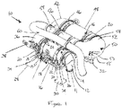
- a selective catalytic reduction (SCR) system suitable for automotive applications such as on a vehicle or work machine is shown in Figures 1-5 .
- the system generally designated 10, comprises an exhaust cap 12 which has a cap inlet 11 which in use will be connected to a diesel engine exhaust, and most likely a turbocharger outlet of the engine exhaust.
- the exhaust cap 12 also includes a cap outlet 14, which is substantially 90 degrees to the cap inlet 11 such that the cap 12 turns the exhaust flow through substantially 90 degrees so that it then proceeds in a generally horizontal direction.
- the cap outlet 14 has a cross sectional area which is greater than that of the cap inlet 11, so that the exhaust flow is expanding as it leaves the cap 12.
- DOC diesel oxidation catalyst
- the DOC canister 16 is supported by a cradle, or frame, 18 and is attached to the cradle by retaining straps 20.
- Each strap 20 in a pair has one end 22 fixed to the cradle 18 and a free looped end 24 connected to the free end of the other strap making up that pair.
- the looped ends 24 of each pair of straps 20 are connected to one another using a known threaded fixing arrangement 26 which allows the straps to be tightened around the canister to secure it to the cradle 18, and can also be disconnected to open the straps and allow the canister to be removed when necessary.
- the cradle 18 is supported on a pair of rear legs or supports 28,30 and a front leg or support 32. Each of the legs or supports 28,30,32 is connected to the cradle 18 using elastomeric top mounts 34 in order to isolate the cradle from unwanted vibration.
- an elbow 36 Downstream of the DOC canister 16 is an elbow 36 which turns the exhaust flow substantially through 90 degrees whilst maintaining the generally horizontal flow path.
- Attached to the elbow 36 is a diesel exhaust fluid (DEF) dosing unit 38, which has an injector (not shown) and is connectable to a source of DEF so that it may inject the DEF into the exhaust flow as it passes through the elbow.
- the DEF injector extends into the interior of the elbow.
- hydcat hydrolysis catalyst
- hydcat canister 40 Downstream of the elbow 36 is a hydrolysis catalyst (“hydcat") contained within a hydcat canister 40, which is best seen in Figure 3 .
- the hydcat canister 40 is releasably attached to the cradle 18 in the same manner as the DOC canister 16.
- the hydcat canister 40 is fixed to the elbow 36, whereby the hydcat canister, elbow and DEF dosing unit 38 are attached and detached from the cradle 18 as a single component.
- a mixer plate (not shown) may be placed in the hydcat canister 40 downstream of the hydcat so as to ensure homogenous mixing of the exhaust gas and ammonia released from the hydcat.
- a first, or upstream, end cap 42 receives the exhaust flow from the hydcat and turns it substantially through a further 90 degrees, so that the exhaust flow is now in the opposite direction to that in which it passes through the DOC canister 16.
- the first end cap 42 has a first end cap inlet 44 and a first end cap outlet 46 which define respective flow paths that lie at substantially 90 degrees to one another.
- the first end cap outlet 46 may have a cross sectional area which is larger than that of the first end cap inlet 44.
- SCR canister 48 Connected to the first end cap outlet 46 is a SCR canister 48 which contains an SCR coated-on filter (SCRF), which can also be referred to as a diesel particulate filter (DPF), and a SCR catalyst of a known type downstream of the SCRF.
- SCRF SCR coated-on filter
- DPF diesel particulate filter
- SCR catalyst of a known type downstream of the SCRF.
- the SCR canister 48 lies on the cradle 18 and is substantially parallel with the DOC canister 16.
- the SCR canister 48 is removably attached to the cradle 18 by straps 20 and fixing arrangements 26 in the same way as the DOC canister 16.
- a second, or downstream, end cap 50 is connected to the downstream end of the SCR canister 48.
- the second end cap 50 has a second end cap inlet 52 and a second end cap outlet 54 which define respective flow paths which are substantially parallel to one another. In other words, the second end cap 50 turns the exhaust flow through substantially 180 degrees after it has exited the SCR canister 48.
- the second end cap inlet 52 may have a cross sectional area which is greater than the second end cap outlet 54 so as to reduce the diameter of the flow path at this point.
- the second end cap 50 may also house NOx and ammonia sensors 55,57 which are used by a SCR controller (not shown) to monitor the performance of the SCR catalyst.
- An ammonia oxidation (AMOx) canister 56 lies downstream of the second end cap 50 and houses an AMOx catalyst of a known type.
- the AMOx canister 56 is mounted on the cradle 18 between the DOC and SCR canisters 16,48 and lies substantially parallel to those canisters. As with the previous canisters 16,48 the AMOx canister 56 is removably attached to the cradle 18 using the same type of straps 20 and fixing arrangements 26.
- the AMOx canister 56 has an exhaust outlet 58 which is in fluid communication with an exhaust pipe 60, which directs the exhaust gas flow to a tailpipe (not shown) and hence to atmosphere.
- the exhaust flow proceeds into the elbow 36.
- the DEF dosing unit 38 injects DEF into the exhaust flow at a controlled rate dictated by a SCR controller and various sensors communicating with the controller.
- the injector of the DEF dosing unit 38 may be positioned so that it injects DEF directly onto the hydrolysis catalyst contained within the hydcat canister 40 downstream of the elbow 36.
- a thermolysis reaction takes place caused by the heat of the exhaust gas, whereby the DEF is converted into ammonia, isocyanic acid and water vapour.
- the presence of the water vapour then permits the hydcat to convert the isocyanic acid into additional ammonia and carbon dioxide.
- the optional mixer plate ensures homogenous mixing of the ammonia and exhaust gas as the exhaust flow leaves the hydcat canister 40 and enters the first end cap 42.
- the first end cap 42 turns the flow through substantially 90 degrees and expands the flow as it enters the SCR canister 48.
- the exhaust flow first passes through the SCRF, where particulate matter is trapped by the SCRF.
- the SCRF is regenerated in a known manner in order to remove the trapped matter.
- the NOx present in the flow reacts with the ammonia, thereby converting the NOx to nitrogen, water and a small amount of carbon dioxide.
- the exhaust flow then enters the second end cap 50, where the relative orientation and variation in cross sectional area of the second end cap inlet 52 and the second end cap outlet 54 turns the flow through substantially 180 degrees and tapers or shrinks the flow diameter.
- the flow then enters the AMOx canister 56 where the AMOx catalyst oxidises ammonia remaining within the exhaust flow to limit the amount of ammonia slipping through the system to atmosphere.
- the present invention By providing a SCR system whose principal components are arranged on a support frame the present invention ensures that the system is as compact as possible whilst being readily accessible for maintenance. Furthermore, by fluidly connecting the various canisters of the SCR system by exhaust passage elbows and/or end caps the present invention provides a compact SCR system in which optimal mixing of exhaust gas and DEF/ammonia is achieved without any detrimental increases in back pressure within the system.
Landscapes
- Engineering & Computer Science (AREA)
- Chemical & Material Sciences (AREA)
- Chemical Kinetics & Catalysis (AREA)
- Combustion & Propulsion (AREA)
- Mechanical Engineering (AREA)
- General Engineering & Computer Science (AREA)
- Health & Medical Sciences (AREA)
- Toxicology (AREA)
- Exhaust Gas After Treatment (AREA)
Abstract
Description
- The present invention relates to selective catalytic reduction (SCR) systems which treat nitrogen oxides in the exhaust gases of diesel engines. More specifically, the present invention is a compact SCR system for use in vehicular applications in particular.
- SCR systems are known and are generally included in the exhaust systems of diesel engines in order to treat the exhaust gases of such engines. Such systems involve the introduction of diesel exhaust fluid (DEF) into exhaust gas flowing in an exhaust passage of an engine. The DEF contains urea which undergoes a hydrolysis and/or thermolysis within the exhaust passage whereby ammonia is produced. The ammonia passes into a SCR catalyst where it reacts with the exhaust gas. In this reaction any nitrogen oxides (NOx) present in the exhaust gas are converted to nitrogen and water before passing out of the exhaust into the atmosphere.
- A SCR system can include the following components:
- A diesel oxidation catalyst (DOC), which oxidises any hydrocarbons and carbon monoxide to produce carbon dioxide and water, and oxidises nitrogen oxide to produce nitrogen dioxide;
- A DEF dosing unit and injector, which injects the DEF into the exhaust passage;
- A hydrolysis catalyst, which hydrolyses the urea in the DEF in order to convert it to ammonia as efficiently as possible;
- An SCR coated-on filter, or diesel particulate filter (DPF), which traps particulate matter in the exhaust flow;
- A SCR catalyst, which catalyses the reaction between the NOx and ammonia now in the exhaust passage to produce nitrogen and water; and
- An ammonia oxidation (AMOx) catalyst, which oxidises any ammonia remaining in the exhaust gas downstream of the SCR to ensure that significant amounts of ammonia do not "slip" out into the atmosphere.
- Along with the SCR catalyst and DEF dosing unit a SCR system will include some, if not all, of the other components listed above. In automotive applications, this can cause problems as the size of the components and the exhaust passage(s) connecting them can be difficult to package within the confines of a vehicle body (e.g. the engine bay/compartment) where space is at a premium. In addition, these components will need to be serviced and/or replaced during the lifespan of the vehicle, and this can increase maintenance time and associated cost if the components are not relatively easy to access and remove.
- One solution to the packaging issue has been proposed is
US8820059 , in which a DOC and a DPF are arranged in parallel with a SCR catalyst, with the components lying on a mount. A DEF dosing unit is provided in a passage which connects opposing ends of these two components. In this arrangement an AMOx catalyst may be present but is not packaged with the aforementioned components. - It is an aim of the present invention to provide a SCR system which is as compact as possible whilst being readily accessible for maintenance. It is a further aim of the present invention to provide a SCR system in which optimal mixing of exhaust gas and DEF/ammonia is achieved without any detrimental increases in back pressure within the system.
- According to a first aspect of the invention there is provided a selective catalytic reduction (SCR) system for treating exhaust gas from a diesel engine. The system comprises a frame, a SCR catalyst contained within a SCR canister, and an ammonia oxidation catalyst contained within an ammonia oxidation canister. Each of the SCR and ammonia oxidation canisters is removably attached to the frame.
- According to a second aspect of the invention there is provided a method of assembling a SCR system for treating exhaust gas from a diesel engine of a vehicle. The method comprises the steps of providing a frame, and attaching the frame to the vehicle. A SCR canister containing a SCR catalyst is removably attached to the frame, and fluidly connected to an exhaust inlet. An ammonia oxidation canister containing an ammonia oxidation catalyst is removably attached to the frame. The ammonia oxidation canister is fluidly connected to the SCR canister and an exhaust outlet.
- A preferred embodiment of the present invention will now be described, by way of example only, with reference to the following drawings, in which:
-
Figure 1 is a perspective view of a selective catalytic reduction (SCR) system; -
Figure 2 is a top view of the SCR system; -
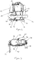
Figure 3 is a left side view of the SCR system; -
Figure 4 is a right side view of the SCR system; and -
Figure 5 is a front view of the SCR system. - A selective catalytic reduction (SCR) system suitable for automotive applications such as on a vehicle or work machine is shown in
Figures 1-5 . The system, generally designated 10, comprises anexhaust cap 12 which has a cap inlet 11 which in use will be connected to a diesel engine exhaust, and most likely a turbocharger outlet of the engine exhaust. Theexhaust cap 12 also includes acap outlet 14, which is substantially 90 degrees to the cap inlet 11 such that thecap 12 turns the exhaust flow through substantially 90 degrees so that it then proceeds in a generally horizontal direction. Thecap outlet 14 has a cross sectional area which is greater than that of the cap inlet 11, so that the exhaust flow is expanding as it leaves thecap 12. - Immediately downstream of the
exhaust cap 12 is a diesel oxidation catalyst (DOC) of a known type, which is housed within aremovable DOC canister 16. TheDOC canister 16 is supported by a cradle, or frame, 18 and is attached to the cradle by retainingstraps 20. It should be noted that any references to the SCR system components or exhaust flow being "horizontal" in this description relate to an arrangement in which the cradle lies substantially horizontal in use. Therefore, for other applications in which the cradle does not lie substantially horizontal then "horizontal" should be interpreted as being substantially parallel to the plane of the cradle. - There are two pairs of
straps 20 holding theDOC canister 16. Eachstrap 20 in a pair has oneend 22 fixed to thecradle 18 and a free looped end 24 connected to the free end of the other strap making up that pair. The looped ends 24 of each pair ofstraps 20 are connected to one another using a known threadedfixing arrangement 26 which allows the straps to be tightened around the canister to secure it to thecradle 18, and can also be disconnected to open the straps and allow the canister to be removed when necessary. - The
cradle 18 is supported on a pair of rear legs or supports 28,30 and a front leg or support 32. Each of the legs or supports 28,30,32 is connected to thecradle 18 usingelastomeric top mounts 34 in order to isolate the cradle from unwanted vibration. - Downstream of the
DOC canister 16 is anelbow 36 which turns the exhaust flow substantially through 90 degrees whilst maintaining the generally horizontal flow path. Attached to theelbow 36 is a diesel exhaust fluid (DEF)dosing unit 38, which has an injector (not shown) and is connectable to a source of DEF so that it may inject the DEF into the exhaust flow as it passes through the elbow. The DEF injector extends into the interior of the elbow. - Downstream of the
elbow 36 is a hydrolysis catalyst ("hydcat") contained within ahydcat canister 40, which is best seen inFigure 3 . Thehydcat canister 40 is releasably attached to thecradle 18 in the same manner as theDOC canister 16. In this preferred embodiment, thehydcat canister 40 is fixed to theelbow 36, whereby the hydcat canister, elbow andDEF dosing unit 38 are attached and detached from thecradle 18 as a single component. A mixer plate (not shown) may be placed in thehydcat canister 40 downstream of the hydcat so as to ensure homogenous mixing of the exhaust gas and ammonia released from the hydcat. A first, or upstream,end cap 42 receives the exhaust flow from the hydcat and turns it substantially through a further 90 degrees, so that the exhaust flow is now in the opposite direction to that in which it passes through theDOC canister 16. Thefirst end cap 42 has a firstend cap inlet 44 and a firstend cap outlet 46 which define respective flow paths that lie at substantially 90 degrees to one another. The firstend cap outlet 46 may have a cross sectional area which is larger than that of the firstend cap inlet 44. - Connected to the first
end cap outlet 46 is aSCR canister 48 which contains an SCR coated-on filter (SCRF), which can also be referred to as a diesel particulate filter (DPF), and a SCR catalyst of a known type downstream of the SCRF. TheSCR canister 48 lies on thecradle 18 and is substantially parallel with theDOC canister 16. TheSCR canister 48 is removably attached to thecradle 18 bystraps 20 and fixingarrangements 26 in the same way as theDOC canister 16. - A second, or downstream,
end cap 50 is connected to the downstream end of theSCR canister 48. Thesecond end cap 50 has a secondend cap inlet 52 and a secondend cap outlet 54 which define respective flow paths which are substantially parallel to one another. In other words, thesecond end cap 50 turns the exhaust flow through substantially 180 degrees after it has exited theSCR canister 48. The secondend cap inlet 52 may have a cross sectional area which is greater than the secondend cap outlet 54 so as to reduce the diameter of the flow path at this point. Thesecond end cap 50 may also house NOx andammonia sensors - An ammonia oxidation (AMOx)
canister 56 lies downstream of thesecond end cap 50 and houses an AMOx catalyst of a known type. TheAMOx canister 56 is mounted on thecradle 18 between the DOC andSCR canisters previous canisters AMOx canister 56 is removably attached to thecradle 18 using the same type ofstraps 20 and fixingarrangements 26. TheAMOx canister 56 has anexhaust outlet 58 which is in fluid communication with anexhaust pipe 60, which directs the exhaust gas flow to a tailpipe (not shown) and hence to atmosphere. - The manner in which the SCR system 10 operates after installation on a diesel engined vehicle will now be described. Exhaust gas exiting the turbocharger outlet of the diesel engine flows into the
exhaust cap 12 via cap inlet 11. The shape of theexhaust cap 12 and the aforementioned increase in cross sectional area of the exhaust flow path between the cap inlet 11 andcap outlet 14 serves to turn the flow 90 degrees to a generally horizontal orientation and also expands the exhaust flow as it flows towards theDOC canister 16. As the exhaust gases flow through the DOC catalyst contained within theDOC canister 16 the DOC catalyst coverts carbon monoxide and hydrocarbons within the exhaust gas into carbon dioxide and water vapour, and some of the nitrogen oxide into nitrogen dioxide. - After flowing through the
DOC canister 16, the exhaust flow proceeds into theelbow 36. As the flow turns substantially 90 degrees around the elbow theDEF dosing unit 38 injects DEF into the exhaust flow at a controlled rate dictated by a SCR controller and various sensors communicating with the controller. The injector of theDEF dosing unit 38 may be positioned so that it injects DEF directly onto the hydrolysis catalyst contained within thehydcat canister 40 downstream of theelbow 36. Following the injection of the aqueous urea DEF a thermolysis reaction takes place caused by the heat of the exhaust gas, whereby the DEF is converted into ammonia, isocyanic acid and water vapour. The presence of the water vapour then permits the hydcat to convert the isocyanic acid into additional ammonia and carbon dioxide. The optional mixer plate ensures homogenous mixing of the ammonia and exhaust gas as the exhaust flow leaves thehydcat canister 40 and enters thefirst end cap 42. - Due to the relative orientation and variation in cross sectional area of the first
end cap inlet 44 and the firstend cap outlet 46, thefirst end cap 42 turns the flow through substantially 90 degrees and expands the flow as it enters theSCR canister 48. In theSCR canister 48 the exhaust flow first passes through the SCRF, where particulate matter is trapped by the SCRF. When it is determined that the level of particulate matter trapped in the SCRF has exceeded a certain value, the SCRF is regenerated in a known manner in order to remove the trapped matter. - As the exhaust gases flow through the SCR catalyst the NOx present in the flow reacts with the ammonia, thereby converting the NOx to nitrogen, water and a small amount of carbon dioxide. The exhaust flow then enters the
second end cap 50, where the relative orientation and variation in cross sectional area of the secondend cap inlet 52 and the secondend cap outlet 54 turns the flow through substantially 180 degrees and tapers or shrinks the flow diameter. The flow then enters theAMOx canister 56 where the AMOx catalyst oxidises ammonia remaining within the exhaust flow to limit the amount of ammonia slipping through the system to atmosphere. - By providing a SCR system whose principal components are arranged on a support frame the present invention ensures that the system is as compact as possible whilst being readily accessible for maintenance. Furthermore, by fluidly connecting the various canisters of the SCR system by exhaust passage elbows and/or end caps the present invention provides a compact SCR system in which optimal mixing of exhaust gas and DEF/ammonia is achieved without any detrimental increases in back pressure within the system.
- Modifications and improvements may be incorporated without departing from the scope of the present invention.
Claims (14)
- A selective catalytic reduction (SCR) system for treating exhaust gas from a diesel engine, the system comprising:a frame;a SCR catalyst contained within a SCR canister; andan ammonia oxidation catalyst contained within an ammonia oxidation canister;wherein each of the SCR and ammonia oxidation canisters is removably attached to the frame.
- The system of claim 1, wherein the SCR and ammonia oxidation canisters are substantially parallel to one another on the frame.
- The system of either preceding claim, wherein the SCR canister includes a SCR coated-on particulate filter located upstream of the SCR catalyst.
- The system of any preceding claim, further comprising a diesel oxidation catalyst contained within a diesel oxidation canister located upstream of the SCR canister, wherein the diesel oxidation canister is removably attached to the frame.
- The system of claim 4, wherein all three canisters are substantially parallel to one another, and the ammonia oxidation canister is located between the diesel oxidation and SCR canisters.
- The system of either claim 4 or claim 5, further comprising an exhaust cap located upstream of the diesel oxidation catalyst and connectable to an outlet of the diesel engine, wherein the exhaust cap has a cap inlet and a cap outlet and the cap outlet has a greater cross sectional area than that of the cap inlet.
- The system of any preceding claim, further comprising:a diesel exhaust fluid (DEF) dosing unit having an injector; andan exhaust passage elbow which turns the exhaust gas through substantially 90 degrees upstream of the SCR catalyst;wherein the injector is arranged to inject DEF into the exhaust passage elbow.
- The system of any preceding claim, further comprising a hydrolysis catalyst upstream of the SCR catalyst, wherein the hydrolysis catalyst is contained within a hydrolysis catalyst canister which is removably attached to the frame.
- The system of claim 8, wherein the hydrolysis canister also contains a mixer plate downstream of the hydrolysis catalyst.
- The system of claim 8 or claim 9, wherein the hydrolysis catalyst canister lies substantially at right angles to the SCR and ammonia oxidation canisters.
- The system of any of claims 8 to 10, further comprising an upstream end cap upstream of the SCR canister, wherein the upstream end cap turns the exhaust gas through substantially 90 degrees between the hydrolysis canister and the SCR canister, the upstream end cap having an upstream end cap inlet and an upstream end cap outlet, and wherein the upstream end cap outlet has a cross sectional area which is greater than that of the upstream end cap inlet.
- The system of any preceding claim, further comprising a downstream end cap downstream of the SCR canister, wherein the downstream end cap turns the exhaust gas through substantially 180 degrees between the SCR canister and the ammonia oxidation canister, the downstream end cap having a downstream end cap inlet and a downstream end cap outlet, and wherein the downstream end cap inlet has a cross sectional area which is greater than that of the downstream end cap outlet.
- The system of any preceding claim, wherein the frame is supported by a plurality of legs or supports, and each leg or support is secured to the frame by an elastomeric vibration isolating member.
- A method of assembling a selective catalytic reduction (SCR) system for treating exhaust gas from a diesel engine of a vehicle, the method comprising the steps of:providing a frame;attaching the frame to the vehicle;removably attaching a SCR canister containing a SCR catalyst to the frame, and fluidly connecting the SCR canister to an exhaust inlet;removably attaching an ammonia oxidation canister containing an ammonia oxidation catalyst to the frame; andfluidly connecting the ammonia oxidation canister to the SCR canister and an exhaust outlet.
Priority Applications (5)
| Application Number | Priority Date | Filing Date | Title |
|---|---|---|---|
| EP17159838.6A EP3372798B1 (en) | 2017-03-08 | 2017-03-08 | A compact selective catalytic reduction system |
| PCT/EP2018/055826 WO2018162673A1 (en) | 2017-03-08 | 2018-03-08 | A compact selective catalytic reduction system |
| CN201880015109.9A CN110382833B (en) | 2017-03-08 | 2018-03-08 | Compact Selective Catalytic Reduction System |
| JP2019543011A JP2020510151A (en) | 2017-03-08 | 2018-03-08 | Compact selective catalytic reduction system |
| US16/490,857 US11225893B2 (en) | 2017-03-08 | 2018-03-08 | Compact selective catalytic reduction system |
Applications Claiming Priority (1)
| Application Number | Priority Date | Filing Date | Title |
|---|---|---|---|
| EP17159838.6A EP3372798B1 (en) | 2017-03-08 | 2017-03-08 | A compact selective catalytic reduction system |
Publications (2)
| Publication Number | Publication Date |
|---|---|
| EP3372798A1 true EP3372798A1 (en) | 2018-09-12 |
| EP3372798B1 EP3372798B1 (en) | 2020-03-04 |
Family
ID=58266893
Family Applications (1)
| Application Number | Title | Priority Date | Filing Date |
|---|---|---|---|
| EP17159838.6A Active EP3372798B1 (en) | 2017-03-08 | 2017-03-08 | A compact selective catalytic reduction system |
Country Status (5)
| Country | Link |
|---|---|
| US (1) | US11225893B2 (en) |
| EP (1) | EP3372798B1 (en) |
| JP (1) | JP2020510151A (en) |
| CN (1) | CN110382833B (en) |
| WO (1) | WO2018162673A1 (en) |
Families Citing this family (1)
| Publication number | Priority date | Publication date | Assignee | Title |
|---|---|---|---|---|
| US11286828B1 (en) * | 2020-09-25 | 2022-03-29 | Dinex A/S | Diesel exhaust treatment apparatus and methods |
Citations (5)
| Publication number | Priority date | Publication date | Assignee | Title |
|---|---|---|---|---|
| US20100236224A1 (en) * | 2009-03-20 | 2010-09-23 | Basf Catalysts Llc | Emissions Treatment System With Lean NOx Trap |
| WO2013160657A1 (en) * | 2012-04-24 | 2013-10-31 | Perkins Engines Company Limited | Emissions cleaning module for an engine |
| US20140237998A1 (en) * | 2013-02-22 | 2014-08-28 | Caterpillar Inc. | Mounting assembly for reductant injector with thermal isolation and sealing gasket |
| WO2014167351A2 (en) * | 2013-04-11 | 2014-10-16 | Perkins Engines Company Limited | Emissions cleaning module |
| EP3121404A1 (en) * | 2014-03-20 | 2017-01-25 | Yanmar Co., Ltd. | Engine device |
Family Cites Families (17)
| Publication number | Priority date | Publication date | Assignee | Title |
|---|---|---|---|---|
| JP2005155404A (en) * | 2003-11-25 | 2005-06-16 | Komatsu Ltd | Exhaust gas purification device for internal combustion engine |
| DE102006038288A1 (en) * | 2006-08-16 | 2008-02-21 | Man Nutzfahrzeuge Aktiengesellschaft | aftertreatment system |
| JP5066400B2 (en) * | 2007-07-13 | 2012-11-07 | 日野自動車株式会社 | Exhaust purification device |
| JP4995689B2 (en) * | 2007-10-26 | 2012-08-08 | 日野自動車株式会社 | Exhaust purification device |
| DE102008010071A1 (en) * | 2008-02-19 | 2009-08-20 | Man Nutzfahrzeuge Ag | Compact exhaust aftertreatment system |
| EP2110528B2 (en) * | 2008-04-18 | 2017-04-19 | Daimler AG | Apparatus for treating an exhaust gas stream with removable module |
| US8191668B2 (en) * | 2008-08-07 | 2012-06-05 | Caterpillar Inc. | Mounting assembly for emissions control system |
| JP5179286B2 (en) * | 2008-08-11 | 2013-04-10 | 日立建機株式会社 | Exhaust gas purification device |
| JP5319325B2 (en) * | 2009-02-24 | 2013-10-16 | 日野自動車株式会社 | Support structure for exhaust purification system |
| DE102010014037A1 (en) * | 2009-04-02 | 2010-11-04 | Cummins Filtration IP, Inc., Minneapolis | Reducing agent i.e. urea, decomposition system, has reducing agent injector coupled with exhaust chamber, where reducing agent injector is fixed in reducing agent injection connection part with exhaust gas in exhaust chamber |
| US20120017574A1 (en) * | 2010-07-20 | 2012-01-26 | Saad Hasan | Strap for securing exhaust treatment device |
| CN104040125A (en) * | 2012-01-06 | 2014-09-10 | 沃尔沃建造设备有限公司 | Exhaust gas reduction device for heavy equipment |
| DE102012009940A1 (en) * | 2012-05-18 | 2013-11-21 | Daimler Ag | Crash-tolerant system arrangement in a motor vehicle engine compartment |
| US9016050B2 (en) * | 2012-12-19 | 2015-04-28 | Caterpillar Inc. | Aftertreatment system incorporating hydrolysis catalyst with particulate filtration and SCR |
| JP6087804B2 (en) * | 2013-12-26 | 2017-03-01 | 株式会社クボタ | diesel engine |
| CN207363741U (en) * | 2014-06-30 | 2018-05-15 | 优美科两合公司 | Exhaust aftertreatment systems for diesel engines |
| CA2898553C (en) * | 2014-12-01 | 2016-08-09 | Hirokazu Ashikawa | Dump truck |
-
2017
- 2017-03-08 EP EP17159838.6A patent/EP3372798B1/en active Active
-
2018
- 2018-03-08 CN CN201880015109.9A patent/CN110382833B/en active Active
- 2018-03-08 WO PCT/EP2018/055826 patent/WO2018162673A1/en not_active Ceased
- 2018-03-08 JP JP2019543011A patent/JP2020510151A/en active Pending
- 2018-03-08 US US16/490,857 patent/US11225893B2/en active Active
Patent Citations (6)
| Publication number | Priority date | Publication date | Assignee | Title |
|---|---|---|---|---|
| US20100236224A1 (en) * | 2009-03-20 | 2010-09-23 | Basf Catalysts Llc | Emissions Treatment System With Lean NOx Trap |
| WO2013160657A1 (en) * | 2012-04-24 | 2013-10-31 | Perkins Engines Company Limited | Emissions cleaning module for an engine |
| US20140237998A1 (en) * | 2013-02-22 | 2014-08-28 | Caterpillar Inc. | Mounting assembly for reductant injector with thermal isolation and sealing gasket |
| US8820059B1 (en) | 2013-02-22 | 2014-09-02 | Caterpillar Inc. | Mounting assembly for reductant injector with thermal isolation and sealing gasket |
| WO2014167351A2 (en) * | 2013-04-11 | 2014-10-16 | Perkins Engines Company Limited | Emissions cleaning module |
| EP3121404A1 (en) * | 2014-03-20 | 2017-01-25 | Yanmar Co., Ltd. | Engine device |
Also Published As
| Publication number | Publication date |
|---|---|
| US11225893B2 (en) | 2022-01-18 |
| CN110382833A (en) | 2019-10-25 |
| JP2020510151A (en) | 2020-04-02 |
| CN110382833B (en) | 2022-03-01 |
| WO2018162673A1 (en) | 2018-09-13 |
| EP3372798B1 (en) | 2020-03-04 |
| US20200003099A1 (en) | 2020-01-02 |
Similar Documents
| Publication | Publication Date | Title |
|---|---|---|
| EP2984312B1 (en) | Emissions cleaning module | |
| US11141696B2 (en) | Single module integrated aftertreatment module | |
| US9528411B2 (en) | Emissions cleaning module | |
| EP4579067A3 (en) | Exhaust gas treatment system with upstream scr catalyst | |
| EP2199554A1 (en) | Exhaust gas purifier | |
| CA2847035A1 (en) | Passenger service vehicle | |
| KR20140005295A (en) | Poka-yoke mounting system for an exhaust treatment device | |
| GB2465151A (en) | Engine exhaust treatment unit | |
| US11225893B2 (en) | Compact selective catalytic reduction system | |
| GB2531639A (en) | Adjustable mounting system for aftertreatment or exhaust components | |
| EP3150812A1 (en) | A method for injecting reductant into an exhaust gas of a power system | |
| WO2014040701A8 (en) | Scr module | |
| KR100980631B1 (en) | Element storage tank of SCC system and heating device of urea supply line | |
| KR100820685B1 (en) | SCC R Purifier | |
| WO2008043937A3 (en) | System for treating nitrogen oxides while limiting ammonia emissions |
Legal Events
| Date | Code | Title | Description |
|---|---|---|---|
| PUAI | Public reference made under article 153(3) epc to a published international application that has entered the european phase |
Free format text: ORIGINAL CODE: 0009012 |
|
| STAA | Information on the status of an ep patent application or granted ep patent |
Free format text: STATUS: THE APPLICATION HAS BEEN PUBLISHED |
|
| AK | Designated contracting states |
Kind code of ref document: A1 Designated state(s): AL AT BE BG CH CY CZ DE DK EE ES FI FR GB GR HR HU IE IS IT LI LT LU LV MC MK MT NL NO PL PT RO RS SE SI SK SM TR |
|
| AX | Request for extension of the european patent |
Extension state: BA ME |
|
| STAA | Information on the status of an ep patent application or granted ep patent |
Free format text: STATUS: REQUEST FOR EXAMINATION WAS MADE |
|
| 17P | Request for examination filed |
Effective date: 20190301 |
|
| RBV | Designated contracting states (corrected) |
Designated state(s): AL AT BE BG CH CY CZ DE DK EE ES FI FR GB GR HR HU IE IS IT LI LT LU LV MC MK MT NL NO PL PT RO RS SE SI SK SM TR |
|
| STAA | Information on the status of an ep patent application or granted ep patent |
Free format text: STATUS: EXAMINATION IS IN PROGRESS |
|
| 17Q | First examination report despatched |
Effective date: 20190510 |
|
| GRAP | Despatch of communication of intention to grant a patent |
Free format text: ORIGINAL CODE: EPIDOSNIGR1 |
|
| STAA | Information on the status of an ep patent application or granted ep patent |
Free format text: STATUS: GRANT OF PATENT IS INTENDED |
|
| INTG | Intention to grant announced |
Effective date: 20191001 |
|
| RIN1 | Information on inventor provided before grant (corrected) |
Inventor name: SILVER, RONALD Inventor name: KENNEDY, MARK Inventor name: PETTO, HANNAH Inventor name: EDEN, ALEX Inventor name: REID, BEN Inventor name: PIERCE, DAN Inventor name: KUREEMUN, RIDWAN Inventor name: SHEAD, LEO |
|
| GRAS | Grant fee paid |
Free format text: ORIGINAL CODE: EPIDOSNIGR3 |
|
| GRAA | (expected) grant |
Free format text: ORIGINAL CODE: 0009210 |
|
| STAA | Information on the status of an ep patent application or granted ep patent |
Free format text: STATUS: THE PATENT HAS BEEN GRANTED |
|
| AK | Designated contracting states |
Kind code of ref document: B1 Designated state(s): AL AT BE BG CH CY CZ DE DK EE ES FI FR GB GR HR HU IE IS IT LI LT LU LV MC MK MT NL NO PL PT RO RS SE SI SK SM TR |
|
| REG | Reference to a national code |
Ref country code: GB Ref legal event code: FG4D |
|
| REG | Reference to a national code |
Ref country code: CH Ref legal event code: EP |
|
| REG | Reference to a national code |
Ref country code: AT Ref legal event code: REF Ref document number: 1240610 Country of ref document: AT Kind code of ref document: T Effective date: 20200315 |
|
| REG | Reference to a national code |
Ref country code: DE Ref legal event code: R096 Ref document number: 602017012437 Country of ref document: DE |
|
| REG | Reference to a national code |
Ref country code: IE Ref legal event code: FG4D |
|
| PG25 | Lapsed in a contracting state [announced via postgrant information from national office to epo] |
Ref country code: NO Free format text: LAPSE BECAUSE OF FAILURE TO SUBMIT A TRANSLATION OF THE DESCRIPTION OR TO PAY THE FEE WITHIN THE PRESCRIBED TIME-LIMIT Effective date: 20200604 Ref country code: RS Free format text: LAPSE BECAUSE OF FAILURE TO SUBMIT A TRANSLATION OF THE DESCRIPTION OR TO PAY THE FEE WITHIN THE PRESCRIBED TIME-LIMIT Effective date: 20200304 Ref country code: FI Free format text: LAPSE BECAUSE OF FAILURE TO SUBMIT A TRANSLATION OF THE DESCRIPTION OR TO PAY THE FEE WITHIN THE PRESCRIBED TIME-LIMIT Effective date: 20200304 |
|
| REG | Reference to a national code |
Ref country code: NL Ref legal event code: MP Effective date: 20200304 |
|
| PG25 | Lapsed in a contracting state [announced via postgrant information from national office to epo] |
Ref country code: SE Free format text: LAPSE BECAUSE OF FAILURE TO SUBMIT A TRANSLATION OF THE DESCRIPTION OR TO PAY THE FEE WITHIN THE PRESCRIBED TIME-LIMIT Effective date: 20200304 Ref country code: LV Free format text: LAPSE BECAUSE OF FAILURE TO SUBMIT A TRANSLATION OF THE DESCRIPTION OR TO PAY THE FEE WITHIN THE PRESCRIBED TIME-LIMIT Effective date: 20200304 Ref country code: HR Free format text: LAPSE BECAUSE OF FAILURE TO SUBMIT A TRANSLATION OF THE DESCRIPTION OR TO PAY THE FEE WITHIN THE PRESCRIBED TIME-LIMIT Effective date: 20200304 Ref country code: BG Free format text: LAPSE BECAUSE OF FAILURE TO SUBMIT A TRANSLATION OF THE DESCRIPTION OR TO PAY THE FEE WITHIN THE PRESCRIBED TIME-LIMIT Effective date: 20200604 Ref country code: GR Free format text: LAPSE BECAUSE OF FAILURE TO SUBMIT A TRANSLATION OF THE DESCRIPTION OR TO PAY THE FEE WITHIN THE PRESCRIBED TIME-LIMIT Effective date: 20200605 |
|
| REG | Reference to a national code |
Ref country code: LT Ref legal event code: MG4D |
|
| PG25 | Lapsed in a contracting state [announced via postgrant information from national office to epo] |
Ref country code: NL Free format text: LAPSE BECAUSE OF FAILURE TO SUBMIT A TRANSLATION OF THE DESCRIPTION OR TO PAY THE FEE WITHIN THE PRESCRIBED TIME-LIMIT Effective date: 20200304 |
|
| PG25 | Lapsed in a contracting state [announced via postgrant information from national office to epo] |
Ref country code: SM Free format text: LAPSE BECAUSE OF FAILURE TO SUBMIT A TRANSLATION OF THE DESCRIPTION OR TO PAY THE FEE WITHIN THE PRESCRIBED TIME-LIMIT Effective date: 20200304 Ref country code: LT Free format text: LAPSE BECAUSE OF FAILURE TO SUBMIT A TRANSLATION OF THE DESCRIPTION OR TO PAY THE FEE WITHIN THE PRESCRIBED TIME-LIMIT Effective date: 20200304 Ref country code: CZ Free format text: LAPSE BECAUSE OF FAILURE TO SUBMIT A TRANSLATION OF THE DESCRIPTION OR TO PAY THE FEE WITHIN THE PRESCRIBED TIME-LIMIT Effective date: 20200304 Ref country code: EE Free format text: LAPSE BECAUSE OF FAILURE TO SUBMIT A TRANSLATION OF THE DESCRIPTION OR TO PAY THE FEE WITHIN THE PRESCRIBED TIME-LIMIT Effective date: 20200304 Ref country code: RO Free format text: LAPSE BECAUSE OF FAILURE TO SUBMIT A TRANSLATION OF THE DESCRIPTION OR TO PAY THE FEE WITHIN THE PRESCRIBED TIME-LIMIT Effective date: 20200304 Ref country code: PT Free format text: LAPSE BECAUSE OF FAILURE TO SUBMIT A TRANSLATION OF THE DESCRIPTION OR TO PAY THE FEE WITHIN THE PRESCRIBED TIME-LIMIT Effective date: 20200729 Ref country code: ES Free format text: LAPSE BECAUSE OF FAILURE TO SUBMIT A TRANSLATION OF THE DESCRIPTION OR TO PAY THE FEE WITHIN THE PRESCRIBED TIME-LIMIT Effective date: 20200304 Ref country code: IS Free format text: LAPSE BECAUSE OF FAILURE TO SUBMIT A TRANSLATION OF THE DESCRIPTION OR TO PAY THE FEE WITHIN THE PRESCRIBED TIME-LIMIT Effective date: 20200704 Ref country code: SK Free format text: LAPSE BECAUSE OF FAILURE TO SUBMIT A TRANSLATION OF THE DESCRIPTION OR TO PAY THE FEE WITHIN THE PRESCRIBED TIME-LIMIT Effective date: 20200304 |
|
| REG | Reference to a national code |
Ref country code: CH Ref legal event code: PL |
|
| REG | Reference to a national code |
Ref country code: AT Ref legal event code: MK05 Ref document number: 1240610 Country of ref document: AT Kind code of ref document: T Effective date: 20200304 |
|
| REG | Reference to a national code |
Ref country code: DE Ref legal event code: R097 Ref document number: 602017012437 Country of ref document: DE |
|
| REG | Reference to a national code |
Ref country code: BE Ref legal event code: MM Effective date: 20200331 |
|
| PG25 | Lapsed in a contracting state [announced via postgrant information from national office to epo] |
Ref country code: MC Free format text: LAPSE BECAUSE OF FAILURE TO SUBMIT A TRANSLATION OF THE DESCRIPTION OR TO PAY THE FEE WITHIN THE PRESCRIBED TIME-LIMIT Effective date: 20200304 Ref country code: LU Free format text: LAPSE BECAUSE OF NON-PAYMENT OF DUE FEES Effective date: 20200308 |
|
| PLBE | No opposition filed within time limit |
Free format text: ORIGINAL CODE: 0009261 |
|
| STAA | Information on the status of an ep patent application or granted ep patent |
Free format text: STATUS: NO OPPOSITION FILED WITHIN TIME LIMIT |
|
| PG25 | Lapsed in a contracting state [announced via postgrant information from national office to epo] |
Ref country code: LI Free format text: LAPSE BECAUSE OF NON-PAYMENT OF DUE FEES Effective date: 20200331 Ref country code: AT Free format text: LAPSE BECAUSE OF FAILURE TO SUBMIT A TRANSLATION OF THE DESCRIPTION OR TO PAY THE FEE WITHIN THE PRESCRIBED TIME-LIMIT Effective date: 20200304 Ref country code: IE Free format text: LAPSE BECAUSE OF NON-PAYMENT OF DUE FEES Effective date: 20200308 Ref country code: IT Free format text: LAPSE BECAUSE OF FAILURE TO SUBMIT A TRANSLATION OF THE DESCRIPTION OR TO PAY THE FEE WITHIN THE PRESCRIBED TIME-LIMIT Effective date: 20200304 Ref country code: DK Free format text: LAPSE BECAUSE OF FAILURE TO SUBMIT A TRANSLATION OF THE DESCRIPTION OR TO PAY THE FEE WITHIN THE PRESCRIBED TIME-LIMIT Effective date: 20200304 Ref country code: CH Free format text: LAPSE BECAUSE OF NON-PAYMENT OF DUE FEES Effective date: 20200331 |
|
| 26N | No opposition filed |
Effective date: 20201207 |
|
| PG25 | Lapsed in a contracting state [announced via postgrant information from national office to epo] |
Ref country code: PL Free format text: LAPSE BECAUSE OF FAILURE TO SUBMIT A TRANSLATION OF THE DESCRIPTION OR TO PAY THE FEE WITHIN THE PRESCRIBED TIME-LIMIT Effective date: 20200304 Ref country code: SI Free format text: LAPSE BECAUSE OF FAILURE TO SUBMIT A TRANSLATION OF THE DESCRIPTION OR TO PAY THE FEE WITHIN THE PRESCRIBED TIME-LIMIT Effective date: 20200304 Ref country code: BE Free format text: LAPSE BECAUSE OF NON-PAYMENT OF DUE FEES Effective date: 20200331 |
|
| PG25 | Lapsed in a contracting state [announced via postgrant information from national office to epo] |
Ref country code: TR Free format text: LAPSE BECAUSE OF FAILURE TO SUBMIT A TRANSLATION OF THE DESCRIPTION OR TO PAY THE FEE WITHIN THE PRESCRIBED TIME-LIMIT Effective date: 20200304 Ref country code: MT Free format text: LAPSE BECAUSE OF FAILURE TO SUBMIT A TRANSLATION OF THE DESCRIPTION OR TO PAY THE FEE WITHIN THE PRESCRIBED TIME-LIMIT Effective date: 20200304 Ref country code: CY Free format text: LAPSE BECAUSE OF FAILURE TO SUBMIT A TRANSLATION OF THE DESCRIPTION OR TO PAY THE FEE WITHIN THE PRESCRIBED TIME-LIMIT Effective date: 20200304 |
|
| PG25 | Lapsed in a contracting state [announced via postgrant information from national office to epo] |
Ref country code: MK Free format text: LAPSE BECAUSE OF FAILURE TO SUBMIT A TRANSLATION OF THE DESCRIPTION OR TO PAY THE FEE WITHIN THE PRESCRIBED TIME-LIMIT Effective date: 20200304 Ref country code: AL Free format text: LAPSE BECAUSE OF FAILURE TO SUBMIT A TRANSLATION OF THE DESCRIPTION OR TO PAY THE FEE WITHIN THE PRESCRIBED TIME-LIMIT Effective date: 20200304 |
|
| P01 | Opt-out of the competence of the unified patent court (upc) registered |
Effective date: 20230517 |
|
| PGFP | Annual fee paid to national office [announced via postgrant information from national office to epo] |
Ref country code: DE Payment date: 20250218 Year of fee payment: 9 |
|
| PGFP | Annual fee paid to national office [announced via postgrant information from national office to epo] |
Ref country code: FR Payment date: 20250219 Year of fee payment: 9 |
|
| PGFP | Annual fee paid to national office [announced via postgrant information from national office to epo] |
Ref country code: GB Payment date: 20250221 Year of fee payment: 9 |