EP3372794A1 - Wear indicator for gas turbine engine - Google Patents
Wear indicator for gas turbine engine Download PDFInfo
- Publication number
- EP3372794A1 EP3372794A1 EP18160341.6A EP18160341A EP3372794A1 EP 3372794 A1 EP3372794 A1 EP 3372794A1 EP 18160341 A EP18160341 A EP 18160341A EP 3372794 A1 EP3372794 A1 EP 3372794A1
- Authority
- EP
- European Patent Office
- Prior art keywords
- wear indicator
- gas turbine
- turbine engine
- component
- combination
- Prior art date
- Legal status (The legal status is an assumption and is not a legal conclusion. Google has not performed a legal analysis and makes no representation as to the accuracy of the status listed.)
- Granted
Links
Images




Classifications
-
- F—MECHANICAL ENGINEERING; LIGHTING; HEATING; WEAPONS; BLASTING
- F01—MACHINES OR ENGINES IN GENERAL; ENGINE PLANTS IN GENERAL; STEAM ENGINES
- F01D—NON-POSITIVE DISPLACEMENT MACHINES OR ENGINES, e.g. STEAM TURBINES
- F01D21/00—Shutting-down of machines or engines, e.g. in emergency; Regulating, controlling, or safety means not otherwise provided for
- F01D21/003—Arrangements for testing or measuring
-
- F—MECHANICAL ENGINEERING; LIGHTING; HEATING; WEAPONS; BLASTING
- F01—MACHINES OR ENGINES IN GENERAL; ENGINE PLANTS IN GENERAL; STEAM ENGINES
- F01D—NON-POSITIVE DISPLACEMENT MACHINES OR ENGINES, e.g. STEAM TURBINES
- F01D11/00—Preventing or minimising internal leakage of working-fluid, e.g. between stages
- F01D11/02—Preventing or minimising internal leakage of working-fluid, e.g. between stages by non-contact sealings, e.g. of labyrinth type
- F01D11/025—Seal clearance control; Floating assembly; Adaptation means to differential thermal dilatations
-
- F—MECHANICAL ENGINEERING; LIGHTING; HEATING; WEAPONS; BLASTING
- F01—MACHINES OR ENGINES IN GENERAL; ENGINE PLANTS IN GENERAL; STEAM ENGINES
- F01D—NON-POSITIVE DISPLACEMENT MACHINES OR ENGINES, e.g. STEAM TURBINES
- F01D11/00—Preventing or minimising internal leakage of working-fluid, e.g. between stages
- F01D11/08—Preventing or minimising internal leakage of working-fluid, e.g. between stages for sealing space between rotor blade tips and stator
- F01D11/12—Preventing or minimising internal leakage of working-fluid, e.g. between stages for sealing space between rotor blade tips and stator using a rubstrip, e.g. erodible. deformable or resiliently-biased part
-
- F—MECHANICAL ENGINEERING; LIGHTING; HEATING; WEAPONS; BLASTING
- F01—MACHINES OR ENGINES IN GENERAL; ENGINE PLANTS IN GENERAL; STEAM ENGINES
- F01D—NON-POSITIVE DISPLACEMENT MACHINES OR ENGINES, e.g. STEAM TURBINES
- F01D17/00—Regulating or controlling by varying flow
- F01D17/02—Arrangement of sensing elements
-
- G—PHYSICS
- G01—MEASURING; TESTING
- G01B—MEASURING LENGTH, THICKNESS OR SIMILAR LINEAR DIMENSIONS; MEASURING ANGLES; MEASURING AREAS; MEASURING IRREGULARITIES OF SURFACES OR CONTOURS
- G01B21/00—Measuring arrangements or details thereof, where the measuring technique is not covered by the other groups of this subclass, unspecified or not relevant
- G01B21/16—Measuring arrangements or details thereof, where the measuring technique is not covered by the other groups of this subclass, unspecified or not relevant for measuring distance of clearance between spaced objects
-
- F—MECHANICAL ENGINEERING; LIGHTING; HEATING; WEAPONS; BLASTING
- F05—INDEXING SCHEMES RELATING TO ENGINES OR PUMPS IN VARIOUS SUBCLASSES OF CLASSES F01-F04
- F05D—INDEXING SCHEME FOR ASPECTS RELATING TO NON-POSITIVE-DISPLACEMENT MACHINES OR ENGINES, GAS-TURBINES OR JET-PROPULSION PLANTS
- F05D2250/00—Geometry
- F05D2250/20—Three-dimensional
- F05D2250/23—Three-dimensional prismatic
- F05D2250/232—Three-dimensional prismatic conical
-
- F—MECHANICAL ENGINEERING; LIGHTING; HEATING; WEAPONS; BLASTING
- F05—INDEXING SCHEMES RELATING TO ENGINES OR PUMPS IN VARIOUS SUBCLASSES OF CLASSES F01-F04
- F05D—INDEXING SCHEME FOR ASPECTS RELATING TO NON-POSITIVE-DISPLACEMENT MACHINES OR ENGINES, GAS-TURBINES OR JET-PROPULSION PLANTS
- F05D2260/00—Function
- F05D2260/80—Diagnostics
Definitions
- the subject matter disclosed herein generally relates to gas turbine engines and, more particularly, to a method and an apparatus for detecting blade tip clearance for a gas turbine engine.
- Gas turbine engines are used in numerous applications, one of which is for providing thrust to an airplane.
- Gas turbines comprise a number of blades in different sections that rotate in order to generate thrust.
- designers have reduced the clearance between blades and inner surfaces of the gas turbine engine. This reduced clearance leads to less room for blade rotation and thus the blade clearance must be accurately monitored.
- a wear indicator and a component of a gas turbine engine is provided.
- the wear indicator is secured to a surface of the component of the gas turbine engine.
- the wear indicator comprising: a first side delaminates when impacted by a blade of the gas turbine engine; a second side parallel to the first side, the second side being secured to a surface of the component of the gas turbine engine; a mid-section interposed between the first side and the second side; and a reference dimension remains constant when the first side delaminates.
- further embodiments of the combination of the wear indicator and the component of the gas turbine engine may include where the reference dimension remains constant throughout the midsection from the first side to the second side.
- further embodiments of the combination of the wear indicator and the component of the gas turbine engine may include where the wear indicator further comprises an orifice initiating at the first side and extending through the midsection to the second side.
- further embodiments of the combination of the wear indicator and the component of the gas turbine engine may include where the first side has a first surface area and the second side has a second surface area larger than the first surface area.
- further embodiments of the combination of the wear indicator and the component of the gas turbine engine may include where the wear indicator has a conical frustum shape.
- further embodiments of the combination of the wear indicator and the component of the gas turbine engine may include where the midsection includes one outer surface between the first side and the second side.
- further embodiments of the combination of the wear indicator and the component of the gas turbine engine may include where the midsection includes at least one outer surface between the first side and the second side; and the at least one outer surface includes an inscribed measurement scale.
- further embodiments of the combination of the wear indicator and the component of the gas turbine engine may include where the orifice has a circular shape.
- further embodiments of the combination of the wear indicator and the component of the gas turbine engine may include where the at least one selected reference dimension includes a diameter of the orifice.
- further embodiments of the combination of the wear indicator and the component of the gas turbine engine may include where the orifice is perpendicular to the first side and the second side.
- further embodiments of the combination of the wear indicator and the component of the gas turbine engine may include where the at least one reference dimension includes an outer diameter of the second side.
- further embodiments of the combination of the wear indicator and the component of the gas turbine engine may include where the orifice includes an inner diameter that varies in size from the first side to the second side.
- further embodiments of the combination of the wear indicator and the component of the gas turbine engine may include where the inner diameter at the first side is greater in size than the inner diameter at the second side.
- further embodiments of the combination of the wear indicator and the component of the gas turbine engine may include where the inner diameter at the second side is greater in size than the inner diameter at the first side.
- further embodiments of the combination of the wear indicator and the component of the gas turbine engine may include where the wear indicator includes a plurality of blind holes originating from the second side and each terminating within the midsection.
- further embodiments of the combination of the wear indicator and the component of the gas turbine engine may include where each blind hole terminates at a different depth dimension within the midsection.
- a method of detecting blade clearance in a gas turbine engine comprising: attaching one or more wear indicators to an inner surface of a gas turbine engine opposite a blade of the gas turbine engine; capturing a baseline set of measurements of each wear indicator; operating the gas turbine engine at a first selected speed for a first period of time; shutting down the gas turbine engine to allow for cooling when the first period of time has ended; and capturing a first set of measurements of each wear indicator.
- further embodiments of the method may include operating the gas turbine engine at a second selected speed for a second period of time; shutting down the gas turbine engine to allow for cooling when the second period of time has ended; and capturing a second set of measurements of each wear indicator.
- further embodiments of the combination of the wear indicator and the component of the gas turbine engine may include where capturing a first set of measurements of each wear indicator includes capturing photographs of each wear indicator.
- further embodiments of the combination of the wear indicator and the component of the gas turbine engine may include inscribing a measurement scale on the wear indicator prior to attaching each wear indicator to the inner surface of the gas turbine engine.
- FIG. 1 schematically illustrates a gas turbine engine 20.
- the gas turbine engine 20 is disclosed herein as a two-spool turbofan that generally incorporates a fan section 22, a compressor section 24, a combustor section 26 and a turbine section 28.
- Alternative engines might include an augmentor section (not shown) among other systems or features.
- the fan section 22 drives air along a bypass flow path B in a bypass duct, while the compressor section 24 drives air along a core flow path C for compression and communication into the combustor section 26 then expansion through the turbine section 28.
- the exemplary engine 20 generally includes a low speed spool 30 and a high speed spool 32 mounted for rotation about an engine central longitudinal axis A relative to an engine static structure 36 via several bearing systems 38. It should be understood that various bearing systems 38 at various locations may alternatively or additionally be provided, and the location of bearing systems 38 may be varied as appropriate to the application.
- the low speed spool 30 generally includes an inner shaft 40 that interconnects a fan 42, a low pressure compressor 44 and a low pressure turbine 46.
- the inner shaft 40 is connected to the fan 42 through a speed change mechanism, which in exemplary gas turbine engine 20 is illustrated as a geared architecture 48 to drive the fan 42 at a lower speed than the low speed spool 30.
- the high speed spool 32 includes an outer shaft 50 that interconnects a high pressure compressor 52 and high pressure turbine 54.
- a combustor 56 is arranged in exemplary gas turbine 20 between the high pressure compressor 52 and the high pressure turbine 54.
- An engine static structure 36 is arranged generally between the high pressure turbine 54 and the low pressure turbine 46.
- the engine static structure 36 further supports bearing systems 38 in the turbine section 28.
- the inner shaft 40 and the outer shaft 50 are concentric and rotate via bearing systems 38 about the engine central longitudinal axis A which is collinear with their longitudinal axes.
- each of the positions of the fan section 22, compressor section 24, combustor section 26, turbine section 28, and fan drive gear system 48 may be varied.
- gear system 48 may be located aft of combustor section 26 or even aft of turbine section 28, and fan section 22 may be positioned forward or aft of the location of gear system 48.
- the engine 20 in one example is a high-bypass geared aircraft engine.
- the engine 20 bypass ratio is greater than about six (6), with an example embodiment being greater than about ten (10)
- the geared architecture 48 is an epicyclic gear train, such as a planetary gear system or other gear system, with a gear reduction ratio of greater than about 2.3
- the low pressure turbine 46 has a pressure ratio that is greater than about five.
- the engine 20 bypass ratio is greater than about ten (10:1)
- the fan diameter is significantly larger than that of the low pressure compressor 44
- the low pressure turbine 46 has a pressure ratio that is greater than about five 5:1.
- Low pressure turbine 46 pressure ratio is pressure measured prior to inlet of low pressure turbine 46 as related to the pressure at the outlet of the low pressure turbine 46 prior to an exhaust nozzle.
- the geared architecture 48 may be an epicycle gear train, such as a planetary gear system or other gear system, with a gear reduction ratio of greater than about 2.3:1. It should be understood, however, that the above parameters are only exemplary of one embodiment of a geared architecture engine and that the present disclosure is applicable to other gas turbine engines including direct drive turbofans.
- the fan section 22 of the engine 20 is designed for a particular flight condition--typically cruise at about 0.8Mach and about 35,000 feet (10,688 meters).
- 'TSFC' Thrust Specific Fuel Consumption
- Low fan pressure ratio is the pressure ratio across the fan blade alone, without a Fan Exit Guide Vane (“FEGV”) system.
- the low fan pressure ratio as disclosed herein according to one non-limiting embodiment is less than about 1.45.
- Low corrected fan tip speed is the actual fan tip speed in ft/sec divided by an industry standard temperature correction of [(Tram °R)/(518.7 °R)]0.5.
- the "Low corrected fan tip speed” as disclosed herein according to one non-limiting embodiment is less than about 1150 ft/second (350.5 m/sec).
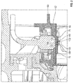
- FIG. 2 shows a cross-sectional view of a rub button or wear indicator 100 installed in a gas turbine engine 20, in accordance with an embodiment of the disclosure.
- the wear indicator 100 is attached to an inner surface 72 of the gas turbine engine 20 opposite a blade 55 of the gas turbine engine 20.
- One or more wear indicators 100 may be affixed to the inner surface 72 of the gas turbine engine 20 in order to monitor the clearance between the blade 55 and the inner surface 72, a method discussed further below in FIG. 7 .
- the wear indicator 100 has been installed in the high pressure turbine 54 of the gas turbine engine 20.
- An abradable coating 74 may be applied on the inner surface 72 of the gas turbine engine 20 and the wear indicator 100 may be attached to the abradable coating 74 on the inner surface 72.
- the abradable coating 74 is designed to provide protection for the inner surface 72 against a blade 55 strike. If a blade 55 were to extend towards the inner surface 72 then the abradable coating 74 shall be struck first and absorb the impact of the blade 55 to prevent damage to the inner surface 72.
- the wear indicator 100 may be attached to the inner surface 72 using an adhesive (not shown) that may or may not need a curing to adhere the wear indicator 100 to the inner surface 72.
- the wear indicator 100 may be affixed to the inner surface 72 proximate a blade monitoring probe 60.
- the blade monitoring probe 60 may be configured to measure various performance parameters of the blade 55 including but not limited to blade timing and blade clearance.
- the blade monitoring probe 60 may capture these various performance parameters wirelessly. Data captured using the wear indicator 100 may then later be compared to data captured by the blade monitoring probe 60 in order to adjust the operation of the blade monitoring probe 60 to improve the performance of the blade monitoring probe 60.
- the blade monitoring probe 60 may be a Pentair CapaciSense system.
- the blade monitoring probe 60 may be secured in place by a blade outer air seal 62.
- the wear indicator 100 may comprise a first side 120 having a first surface area 122 and a second side 130 parallel to the first side 120.
- the second side 130 has a second surface area 132.
- the wear indicator 100 also comprises a mid-section 140 interposed between the first side 120 and the second side 130.
- the second surface area 132 may be larger than the first surface area 122.
- the second side of the wear indicator 100 is affixed to the inner surface 72 of the gas turbine engine 20. If the blade 55 strikes the wear indicator 100 then a layer of the wear indicator 100 will be removed from the first side 120. Thus, the first side 120 delaminates when impacted by a blade 55 of the gas turbine engine 20.
- Delaminate may be understood to mean the removal of material from the wear indicator 100 in layers 170.
- the wear indicator 100 further comprises an orifice 150 initiating at the first side 120 and extending through a midsection 140 to the second side 130.
- the mid-section 140 includes at least one reference dimension.
- the reference dimension may be a single dimension on the wear indicator 100, such as for example an inner diameter (e.g. ID1) of the wear indicator 100, an outer diameter (e.g. OD3) of the wear indicator 100, or an angle ⁇ of the wear indicator 100.
- the wear indicator 100 may remain constant throughout the midsection 140 from the first side 120 to the second side 130.
- the orifice 150 may have a circular shape.
- the orifice 150 includes at least one reference dimension that remains constant throughout the orifice 150 from the first side 120 to the second side 130.
- the inner diameter ID1 (see FIGs. 4-6 ) of the orifice 150 may serve as the reference dimension.
- the reference dimension may also be a third outer diameter OD3 on the second side 130. As the blade 55 removes layers of the first side 120, the third outer diameter OD3 will stay the same and may serve as a reference dimension for detecting how much of the wear indicator 100 was removed.
- the wear indicator 100 may include various shapes, sizes and reference dimensions not disclosed herein.
- the wear indicator 100 may have various shapes.
- the first side 120 and the second side 130 are both round in shape, which creates one outer surface 142 for the midsection 140 and a conical frustum shape for the wear indicator 100. If the first side 120 and second side 130 had different shapes then the midsection 140 would have more outer surfaces 142. For example, if the first side 130 and the second side 130 were both square then the midsection 140 would have four outer surfaces 142. In an embodiment, the midsection 140 has one outer surface 142. In another embodiment, the wear indicator 100 has a conical frustum shape, as seen in FIG. 3 .
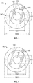
- FIGs. 4-6 in an example show the removal of a layer 170 of material from the wear indicator 100.
- the wear indicator 100 is utilized to measure the clearance between blades 55 and the inner surface 72.
- Various amounts of material may be removed from the wear indicator 100 based upon the various operating parameters of the gas turbine engine 20, such as for example, engine speed, operation duration, and engine internal temperature.
- FIG. 5 shows a view of the first side 120 prior to any material removal
- FIG. 6 shows a view of the first side 120 after material removal by the blade 55.
- the first side 120 Prior to material removal, the first side 120 has a first outer diameter OD1 and the second side 130 has a third outer diameter OD3.
- the height of the wear indicator 100 is reduced from a first height HI to a second height H2, which expands the outer diameter of the first side 120 from the first outer diameter OD1 to the second outer diameter OD2.
- the inner diameter ID1 of the orifice 150 remains unchanged and thus may be used as a reference measurement. For instance, an image may be taken of the first side 120 prior to material removal ( FIG. 5 ) and after material ( FIG. 6 ). In an example, the image may be taken by borescope. Then the images may be compared to each other to determine the amount of material removed. In an example, the inner diameter ID1 remains unchanged after material is removed, thus an image of the first side 120 after material removal ( FIG.
- the second outer diameter OD2 may be analyzed to determine the second outer diameter OD2 using the inner diameter ID1 as a reference.
- the height (H1-H2) of the layer 170 removed may be determined using equations and other known values, such as, for example the angle ⁇ between the second side 130 and the outer surface 142 of the midsection 140, the initial height HI of the wear indicator 100, and the third outer diameter OD3.
- H 1 ⁇ H 2 H 1 ⁇ OD 3 ⁇ OD 2 2 tan ⁇
- the angle ⁇ may be considered a reference dimension.
- the outer surface 142 may also include an inscribed measurement scale 180 as seen in FIGs. 5 and 6 .
- the measurement scale may be a series of numbers and/or shading to help gage how much material has been removed.
- FIGs. 7a and 7b show different possible configurations for the wear indicators 100a-b.
- the wear indicator 100a may be composed of a first side 120a, a second side 130a parallel to the first side 120a and a mid-section 140a interposed between the first side 120a and the second side 130a.
- the wear indicator 100a may include a plurality of blind holes 191-196 originating from the second side 130a and each terminating within the midsection 140a.
- Each of the blind holes 191-196 has depth dimension D1-D6 and each depth dimension D1-D6 may be different.
- each blind hole 191-196 may terminate at a different depth dimension D1-D6 within the midsection 140a.
- each blind hole 191-196 may be exposed indicating the depth of the blade strike.
- the depth dimension D1-D6 of each blind hole 191-196 may be known and thus serve as reference dimensions.
- the wear indicator 100b may be composed of a first side 120b, a second side 130b parallel to the first side 120b and a mid-section 140b interposed between the first side 120b and the second side 130b.
- the wear indicator 100b may include an orifice 150b initiating at the first side 120b and extending through the midsection 140b to the second side 130b.
- the orifice 150b may be circular and may include an internal diameter ID2 that varies in size from the first side 120b to the second side 130b.
- the angle ⁇ 2 that the inner diameter ID2 changes may be known and thus the amount of material removed from first side 120b may be determined similar to the method above in reference to FIGs. 4-6 .
- the angle ⁇ 2 may be considered a reference dimension.
- a fifth outer diameter OD5 of the second side 130b may serve as a reference dimension as layers 170b are removed (delaminated) by a blade from the first side 120b.
- a fourth outer diameter OD4 of the first side 120b may also serve as a reference dimension as layers 170b are removed by a blade from the first side 120b.
- FIG. 8 is a flow chart illustrating a method 800 for detecting blade clearance in a gas turbine engine, in accordance with an embodiment.
- the method 800 of FIG. 8 is described in reference to FIGS. 1-7 and may be performed with an alternate order and include additional steps.
- one or more wear indicators 100 are attached to an inner surface 72 of a gas turbine engine 20 opposite a blade 55 of the gas turbine engine 20.
- the wear indicators 100 may be attached using an adhesive that may require a curing step. Following the use of the adhesive, excessive adhesive may need to be removed from the orifice 150 in the wear indicator 100 to ensure proper reference dimensions.
- the method 800 may also include inscribing a measurement scale 180 on the wear indicator 100 prior to attaching the wear indicator 100 to the inner surface 72.
- a baseline set of measurements of each wear indicator is captured.
- initial dimensions of each wear indicator 100 are captured before any material removal.
- a coordinate measuring machine (CMM) may be used to capture the baseline set of measurements.
- a borescope may be used to take photos and capture the baseline set of measurements.
- the gas turbine engine 20 is operated at a first selected speed for a first period of time. While the engine 20 is operating, a blade monitoring probe 60 may also capture a first set of data during the first time period. The first set of data may include blade clearance measurements.
- the gas turbine engine 20 is shut down to allow for cooling when the first period of time has ended.
- a first set of measurements of each wear indicator 100 is captured.
- a coordinate measuring machine (CMM) may be used to capture the first set of measurements. Additionally, a borescope may be used to take photos and capture the first set of measurements.
- the amount of material removed from the wear indicator 100 may be determined in response to the baseline set of measurements and the first data set, as described above.
- the method 800 may be repeated for a second engine speed, a third engine speed,...etc.
- the engine speeds tested may represent different flight conditions experienced by the engine including but not limited to ground idle, flight idle, max cruise, take-off, max power, and any other flight condition known to one of skill in the art.
Landscapes
- Engineering & Computer Science (AREA)
- Mechanical Engineering (AREA)
- General Engineering & Computer Science (AREA)
- Physics & Mathematics (AREA)
- General Physics & Mathematics (AREA)
- Turbine Rotor Nozzle Sealing (AREA)
- Rolling Contact Bearings (AREA)
Abstract
Description
- The subject matter disclosed herein generally relates to gas turbine engines and, more particularly, to a method and an apparatus for detecting blade tip clearance for a gas turbine engine.
- Gas turbine engines are used in numerous applications, one of which is for providing thrust to an airplane. Gas turbines comprise a number of blades in different sections that rotate in order to generate thrust. In order to improve performance, designers have reduced the clearance between blades and inner surfaces of the gas turbine engine. This reduced clearance leads to less room for blade rotation and thus the blade clearance must be accurately monitored.
- According to one embodiment, in combination a wear indicator and a component of a gas turbine engine is provided. The wear indicator is secured to a surface of the component of the gas turbine engine. The wear indicator comprising: a first side delaminates when impacted by a blade of the gas turbine engine; a second side parallel to the first side, the second side being secured to a surface of the component of the gas turbine engine; a mid-section interposed between the first side and the second side; and a reference dimension remains constant when the first side delaminates.
- In addition to one or more of the features described above, or as an alternative, further embodiments of the combination of the wear indicator and the component of the gas turbine engine may include where the reference dimension remains constant throughout the midsection from the first side to the second side.
- In addition to one or more of the features described above, or as an alternative, further embodiments of the combination of the wear indicator and the component of the gas turbine engine may include where the wear indicator further comprises an orifice initiating at the first side and extending through the midsection to the second side.
- In addition to one or more of the features described above, or as an alternative, further embodiments of the combination of the wear indicator and the component of the gas turbine engine may include where the first side has a first surface area and the second side has a second surface area larger than the first surface area.
- In addition to one or more of the features described above, or as an alternative, further embodiments of the combination of the wear indicator and the component of the gas turbine engine may include where the wear indicator has a conical frustum shape.
- In addition to one or more of the features described above, or as an alternative, further embodiments of the combination of the wear indicator and the component of the gas turbine engine may include where the midsection includes one outer surface between the first side and the second side.
- In addition to one or more of the features described above, or as an alternative, further embodiments of the combination of the wear indicator and the component of the gas turbine engine may include where the midsection includes at least one outer surface between the first side and the second side; and the at least one outer surface includes an inscribed measurement scale.
- In addition to one or more of the features described above, or as an alternative, further embodiments of the combination of the wear indicator and the component of the gas turbine engine may include where the orifice has a circular shape.
- In addition to one or more of the features described above, or as an alternative, further embodiments of the combination of the wear indicator and the component of the gas turbine engine may include where the at least one selected reference dimension includes a diameter of the orifice.
- In addition to one or more of the features described above, or as an alternative, further embodiments of the combination of the wear indicator and the component of the gas turbine engine may include where the orifice is perpendicular to the first side and the second side.
- In addition to one or more of the features described above, or as an alternative, further embodiments of the combination of the wear indicator and the component of the gas turbine engine may include where the at least one reference dimension includes an outer diameter of the second side.
- In addition to one or more of the features described above, or as an alternative, further embodiments of the combination of the wear indicator and the component of the gas turbine engine may include where the orifice includes an inner diameter that varies in size from the first side to the second side.
- In addition to one or more of the features described above, or as an alternative, further embodiments of the combination of the wear indicator and the component of the gas turbine engine may include where the inner diameter at the first side is greater in size than the inner diameter at the second side.
- In addition to one or more of the features described above, or as an alternative, further embodiments of the combination of the wear indicator and the component of the gas turbine engine may include where the inner diameter at the second side is greater in size than the inner diameter at the first side.
- In addition to one or more of the features described above, or as an alternative, further embodiments of the combination of the wear indicator and the component of the gas turbine engine may include where the wear indicator includes a plurality of blind holes originating from the second side and each terminating within the midsection.
- In addition to one or more of the features described above, or as an alternative, further embodiments of the combination of the wear indicator and the component of the gas turbine engine may include where each blind hole terminates at a different depth dimension within the midsection.
- According to another embodiment, a method of detecting blade clearance in a gas turbine engine is provided. The method comprising: attaching one or more wear indicators to an inner surface of a gas turbine engine opposite a blade of the gas turbine engine; capturing a baseline set of measurements of each wear indicator; operating the gas turbine engine at a first selected speed for a first period of time; shutting down the gas turbine engine to allow for cooling when the first period of time has ended; and capturing a first set of measurements of each wear indicator.
- In addition to one or more of the features described above, or as an alternative, further embodiments of the method may include operating the gas turbine engine at a second selected speed for a second period of time; shutting down the gas turbine engine to allow for cooling when the second period of time has ended; and capturing a second set of measurements of each wear indicator.
- In addition to one or more of the features described above, or as an alternative, further embodiments of the combination of the wear indicator and the component of the gas turbine engine may include where capturing a first set of measurements of each wear indicator includes capturing photographs of each wear indicator.
- In addition to one or more of the features described above, or as an alternative, further embodiments of the combination of the wear indicator and the component of the gas turbine engine may include inscribing a measurement scale on the wear indicator prior to attaching each wear indicator to the inner surface of the gas turbine engine.
- The foregoing features and elements may be combined in various combinations without exclusivity, unless expressly indicated otherwise. These features and elements as well as the operation thereof will become more apparent in light of the following description and the accompanying drawings. It should be understood, however, that the following description and drawings are intended to be illustrative and explanatory in nature and non-limiting.
- The following descriptions should not be considered limiting in any way. With reference to the accompanying drawings, like elements are numbered alike:
-
FIG. 1 is a cross-sectional illustration of an aircraft engine, in accordance with an embodiment of the disclosure -
FIG. 2 is a schematic cross-sectional illustration of a wear indicator attached to the inner surface of a gas turbine engine, in accordance with an embodiment of the disclosure; -
FIG. 3 is a schematic isometric illustration of the wear indicator ofFIG. 2 , in accordance with an embodiment of the disclosure; -
FIG. 4 is a schematic cross-sectional illustration of the wear indicator ofFIG. 2 , in accordance with an embodiment of the disclosure; -
FIG. 5 is a schematic illustration of a first side of a wear indicator ofFIG. 2 prior to material removal, in accordance with an embodiment of the disclosure; -
FIG. 6 is a schematic illustration of a first side of a wear indicator ofFIG. 2 post material removal, in accordance with an embodiment of the disclosure; -
FIG. 7a is a schematic cross-sectional illustration of the wear indicator, in accordance with an embodiment of the disclosure; -
FIG. 7b is a schematic cross-sectional illustration of the wear indicator, in accordance with an embodiment of the disclosure; and -
FIG. 8 is a flow process illustrating a method of detecting blade clearance within a gas turbine engine, in accordance with an embodiment of the disclosure. - The detailed description explains embodiments of the present disclosure, together with advantages and features, by way of example with reference to the drawings.
- A detailed description of one or more embodiments of the disclosed apparatus and method are presented herein by way of exemplification and not limitation with reference to the Figures.
-
FIG. 1 schematically illustrates agas turbine engine 20. Thegas turbine engine 20 is disclosed herein as a two-spool turbofan that generally incorporates afan section 22, acompressor section 24, acombustor section 26 and aturbine section 28. Alternative engines might include an augmentor section (not shown) among other systems or features. Thefan section 22 drives air along a bypass flow path B in a bypass duct, while thecompressor section 24 drives air along a core flow path C for compression and communication into thecombustor section 26 then expansion through theturbine section 28. Although depicted as a two-spool turbofan gas turbine engine in the disclosed non-limiting embodiment, it should be understood that the concepts described herein are not limited to use with two-spool turbofans as the teachings may be applied to other types of turbine engines including three-spool architectures. - The
exemplary engine 20 generally includes alow speed spool 30 and ahigh speed spool 32 mounted for rotation about an engine central longitudinal axis A relative to an enginestatic structure 36 viaseveral bearing systems 38. It should be understood thatvarious bearing systems 38 at various locations may alternatively or additionally be provided, and the location ofbearing systems 38 may be varied as appropriate to the application. - The
low speed spool 30 generally includes aninner shaft 40 that interconnects afan 42, alow pressure compressor 44 and alow pressure turbine 46. Theinner shaft 40 is connected to thefan 42 through a speed change mechanism, which in exemplarygas turbine engine 20 is illustrated as a gearedarchitecture 48 to drive thefan 42 at a lower speed than thelow speed spool 30. Thehigh speed spool 32 includes anouter shaft 50 that interconnects ahigh pressure compressor 52 andhigh pressure turbine 54. Acombustor 56 is arranged inexemplary gas turbine 20 between thehigh pressure compressor 52 and thehigh pressure turbine 54. An enginestatic structure 36 is arranged generally between thehigh pressure turbine 54 and thelow pressure turbine 46. The enginestatic structure 36 further supports bearingsystems 38 in theturbine section 28. Theinner shaft 40 and theouter shaft 50 are concentric and rotate viabearing systems 38 about the engine central longitudinal axis A which is collinear with their longitudinal axes. - The core airflow is compressed by the
low pressure compressor 44 then thehigh pressure compressor 52, mixed and burned with fuel in thecombustor 56, then expanded over thehigh pressure turbine 54 andlow pressure turbine 46. Theturbines low speed spool 30 andhigh speed spool 32 in response to the expansion. It will be appreciated that each of the positions of thefan section 22,compressor section 24,combustor section 26,turbine section 28, and fandrive gear system 48 may be varied. For example,gear system 48 may be located aft ofcombustor section 26 or even aft ofturbine section 28, andfan section 22 may be positioned forward or aft of the location ofgear system 48. - The
engine 20 in one example is a high-bypass geared aircraft engine. In a further example, theengine 20 bypass ratio is greater than about six (6), with an example embodiment being greater than about ten (10), the gearedarchitecture 48 is an epicyclic gear train, such as a planetary gear system or other gear system, with a gear reduction ratio of greater than about 2.3 and thelow pressure turbine 46 has a pressure ratio that is greater than about five. In one disclosed embodiment, theengine 20 bypass ratio is greater than about ten (10:1), the fan diameter is significantly larger than that of thelow pressure compressor 44, and thelow pressure turbine 46 has a pressure ratio that is greater than about five 5:1.Low pressure turbine 46 pressure ratio is pressure measured prior to inlet oflow pressure turbine 46 as related to the pressure at the outlet of thelow pressure turbine 46 prior to an exhaust nozzle. The gearedarchitecture 48 may be an epicycle gear train, such as a planetary gear system or other gear system, with a gear reduction ratio of greater than about 2.3:1. It should be understood, however, that the above parameters are only exemplary of one embodiment of a geared architecture engine and that the present disclosure is applicable to other gas turbine engines including direct drive turbofans. - A significant amount of thrust is provided by the bypass flow B due to the high bypass ratio. The
fan section 22 of theengine 20 is designed for a particular flight condition--typically cruise at about 0.8Mach and about 35,000 feet (10,688 meters). The flight condition of 0.8 Mach and 35,000 ft (10,688 meters), with the engine at its best fuel consumption--also known as "bucket cruise Thrust Specific Fuel Consumption ('TSFC')"--is the industry standard parameter of Ibm of fuel being burned divided by lbf of thrust the engine produces at that minimum point. "Low fan pressure ratio" is the pressure ratio across the fan blade alone, without a Fan Exit Guide Vane ("FEGV") system. The low fan pressure ratio as disclosed herein according to one non-limiting embodiment is less than about 1.45. "Low corrected fan tip speed" is the actual fan tip speed in ft/sec divided by an industry standard temperature correction of [(Tram °R)/(518.7 °R)]0.5. The "Low corrected fan tip speed" as disclosed herein according to one non-limiting embodiment is less than about 1150 ft/second (350.5 m/sec). - Referring now to
FIG. 2 , which shows a cross-sectional view of a rub button or wearindicator 100 installed in agas turbine engine 20, in accordance with an embodiment of the disclosure. As seen inFIG. 2 , thewear indicator 100 is attached to aninner surface 72 of thegas turbine engine 20 opposite ablade 55 of thegas turbine engine 20. One ormore wear indicators 100 may be affixed to theinner surface 72 of thegas turbine engine 20 in order to monitor the clearance between theblade 55 and theinner surface 72, a method discussed further below inFIG. 7 . In the embodiment ofFIG. 2 , thewear indicator 100 has been installed in thehigh pressure turbine 54 of thegas turbine engine 20. Anabradable coating 74 may be applied on theinner surface 72 of thegas turbine engine 20 and thewear indicator 100 may be attached to theabradable coating 74 on theinner surface 72. Theabradable coating 74 is designed to provide protection for theinner surface 72 against ablade 55 strike. If ablade 55 were to extend towards theinner surface 72 then theabradable coating 74 shall be struck first and absorb the impact of theblade 55 to prevent damage to theinner surface 72. Thewear indicator 100 may be attached to theinner surface 72 using an adhesive (not shown) that may or may not need a curing to adhere thewear indicator 100 to theinner surface 72. Thewear indicator 100 may be affixed to theinner surface 72 proximate ablade monitoring probe 60. Theblade monitoring probe 60 may be configured to measure various performance parameters of theblade 55 including but not limited to blade timing and blade clearance. Theblade monitoring probe 60 may capture these various performance parameters wirelessly. Data captured using thewear indicator 100 may then later be compared to data captured by theblade monitoring probe 60 in order to adjust the operation of theblade monitoring probe 60 to improve the performance of theblade monitoring probe 60. In one example, theblade monitoring probe 60 may be a Pentair CapaciSense system. Theblade monitoring probe 60 may be secured in place by a bladeouter air seal 62. - As seen in
FIG. 2 , thewear indicator 100 may comprise afirst side 120 having afirst surface area 122 and asecond side 130 parallel to thefirst side 120. Thesecond side 130 has asecond surface area 132. Thewear indicator 100 also comprises a mid-section 140 interposed between thefirst side 120 and thesecond side 130. In an embodiment, thesecond surface area 132 may be larger than thefirst surface area 122. The second side of thewear indicator 100 is affixed to theinner surface 72 of thegas turbine engine 20. If theblade 55 strikes thewear indicator 100 then a layer of thewear indicator 100 will be removed from thefirst side 120. Thus, thefirst side 120 delaminates when impacted by ablade 55 of thegas turbine engine 20. Delaminate may be understood to mean the removal of material from thewear indicator 100 inlayers 170. Thewear indicator 100 further comprises anorifice 150 initiating at thefirst side 120 and extending through amidsection 140 to thesecond side 130. In an embodiment, the mid-section 140 includes at least one reference dimension. The reference dimension may be a single dimension on thewear indicator 100, such as for example an inner diameter (e.g. ID1) of thewear indicator 100, an outer diameter (e.g. OD3) of thewear indicator 100, or an angle α of thewear indicator 100. Thewear indicator 100 may remain constant throughout themidsection 140 from thefirst side 120 to thesecond side 130. In an embodiment, theorifice 150 may have a circular shape. In another embodiment, theorifice 150 includes at least one reference dimension that remains constant throughout theorifice 150 from thefirst side 120 to thesecond side 130. For example, the inner diameter ID1 (seeFIGs. 4-6 ) of theorifice 150 may serve as the reference dimension. Thus, as theblade 55 removes layers of thefirst side 120, the inner diameter ID1 of theorifice 150 may serve as a reference dimension for detecting how much of thewear indicator 100 was removed, which is discussed further below. In another example, the reference dimension may also be a third outer diameter OD3 on thesecond side 130. As theblade 55 removes layers of thefirst side 120, the third outer diameter OD3 will stay the same and may serve as a reference dimension for detecting how much of thewear indicator 100 was removed. As may be appreciated by one of skill in the art, thewear indicator 100 may include various shapes, sizes and reference dimensions not disclosed herein. - Referring now to
FIG. 3 , which shows an isometric view of thewear indicator 100. Thewear indicator 100 may have various shapes. In the illustrated embodiment ofFIG. 3 , thefirst side 120 and thesecond side 130 are both round in shape, which creates oneouter surface 142 for themidsection 140 and a conical frustum shape for thewear indicator 100. If thefirst side 120 andsecond side 130 had different shapes then themidsection 140 would have moreouter surfaces 142. For example, if thefirst side 130 and thesecond side 130 were both square then themidsection 140 would have fourouter surfaces 142. In an embodiment, themidsection 140 has oneouter surface 142. In another embodiment, thewear indicator 100 has a conical frustum shape, as seen inFIG. 3 . - Referring now to
FIGs. 4-6 while continuing to referenceFIGS. 1-3 .FIGs. 4-6 in an example show the removal of alayer 170 of material from thewear indicator 100. As the mentioned above, thewear indicator 100 is utilized to measure the clearance betweenblades 55 and theinner surface 72. Various amounts of material may be removed from thewear indicator 100 based upon the various operating parameters of thegas turbine engine 20, such as for example, engine speed, operation duration, and engine internal temperature.FIG. 5 shows a view of thefirst side 120 prior to any material removal andFIG. 6 shows a view of thefirst side 120 after material removal by theblade 55. Prior to material removal, thefirst side 120 has a first outer diameter OD1 and thesecond side 130 has a third outer diameter OD3. As theblade 55 removes alayer 170 of material, the height of thewear indicator 100 is reduced from a first height HI to a second height H2, which expands the outer diameter of thefirst side 120 from the first outer diameter OD1 to the second outer diameter OD2. Before and after the material removal, the inner diameter ID1 of theorifice 150 remains unchanged and thus may be used as a reference measurement. For instance, an image may be taken of thefirst side 120 prior to material removal (FIG. 5 ) and after material (FIG. 6 ). In an example, the image may be taken by borescope. Then the images may be compared to each other to determine the amount of material removed. In an example, the inner diameter ID1 remains unchanged after material is removed, thus an image of thefirst side 120 after material removal (FIG. 6 ) may be analyzed to determine the second outer diameter OD2 using the inner diameter ID1 as a reference. Once the second outer diameter OD2 is determined then the height (H1-H2) of thelayer 170 removed may be determined using equations and other known values, such as, for example the angle α between thesecond side 130 and theouter surface 142 of themidsection 140, the initial height HI of thewear indicator 100, and the third outer diameter OD3. For instance, the following equation may be used.
- The angle α may be considered a reference dimension. In order to help determine how much material was removed when the
layer 170 is taken off by theblade 55, theouter surface 142 may also include an inscribedmeasurement scale 180 as seen inFIGs. 5 and 6 . For instance, the measurement scale may be a series of numbers and/or shading to help gage how much material has been removed. -
FIGs. 7a and 7b show different possible configurations for thewear indicators 100a-b. As seen inFIG. 7a , thewear indicator 100a may be composed of afirst side 120a, asecond side 130a parallel to thefirst side 120a and amid-section 140a interposed between thefirst side 120a and thesecond side 130a. Thewear indicator 100a may include a plurality of blind holes 191-196 originating from thesecond side 130a and each terminating within themidsection 140a. Each of the blind holes 191-196 has depth dimension D1-D6 and each depth dimension D1-D6 may be different. In an embodiment, each blind hole 191-196 may terminate at a different depth dimension D1-D6 within themidsection 140a. Aslayers 170a delaminate from thefirst side 120a, when a blade strikes, different blind holes 191-196 may be exposed indicating the depth of the blade strike. The depth dimension D1-D6 of each blind hole 191-196 may be known and thus serve as reference dimensions. - As seen in
FIG. 7b , thewear indicator 100b may be composed of afirst side 120b, asecond side 130b parallel to thefirst side 120b and a mid-section 140b interposed between thefirst side 120b and thesecond side 130b. Thewear indicator 100b may include anorifice 150b initiating at thefirst side 120b and extending through themidsection 140b to thesecond side 130b. Theorifice 150b may be circular and may include an internal diameter ID2 that varies in size from thefirst side 120b to thesecond side 130b. The angle α2 that the inner diameter ID2 changes may be known and thus the amount of material removed fromfirst side 120b may be determined similar to the method above in reference toFIGs. 4-6 . The angle α2 may be considered a reference dimension. A fifth outer diameter OD5 of thesecond side 130b may serve as a reference dimension aslayers 170b are removed (delaminated) by a blade from thefirst side 120b. A fourth outer diameter OD4 of thefirst side 120b may also serve as a reference dimension aslayers 170b are removed by a blade from thefirst side 120b. -
FIG. 8 is a flow chart illustrating amethod 800 for detecting blade clearance in a gas turbine engine, in accordance with an embodiment. Themethod 800 ofFIG. 8 is described in reference toFIGS. 1-7 and may be performed with an alternate order and include additional steps. Atblock 804, one ormore wear indicators 100 are attached to aninner surface 72 of agas turbine engine 20 opposite ablade 55 of thegas turbine engine 20. As mentioned above, thewear indicators 100 may be attached using an adhesive that may require a curing step. Following the use of the adhesive, excessive adhesive may need to be removed from theorifice 150 in thewear indicator 100 to ensure proper reference dimensions. Themethod 800 may also include inscribing ameasurement scale 180 on thewear indicator 100 prior to attaching thewear indicator 100 to theinner surface 72. Atblock 806, a baseline set of measurements of each wear indicator is captured. Thus, initial dimensions of eachwear indicator 100 are captured before any material removal. A coordinate measuring machine (CMM) may be used to capture the baseline set of measurements. Additionally, a borescope may be used to take photos and capture the baseline set of measurements. Atblock 808, thegas turbine engine 20 is operated at a first selected speed for a first period of time. While theengine 20 is operating, ablade monitoring probe 60 may also capture a first set of data during the first time period. The first set of data may include blade clearance measurements. Atblock 810, thegas turbine engine 20 is shut down to allow for cooling when the first period of time has ended. Atblock 812, a first set of measurements of eachwear indicator 100 is captured. A coordinate measuring machine (CMM) may be used to capture the first set of measurements. Additionally, a borescope may be used to take photos and capture the first set of measurements. - The amount of material removed from the
wear indicator 100 may be determined in response to the baseline set of measurements and the first data set, as described above. Themethod 800 may be repeated for a second engine speed, a third engine speed,...etc. The engine speeds tested (first engine speed, second engine speed..etc) may represent different flight conditions experienced by the engine including but not limited to ground idle, flight idle, max cruise, take-off, max power, and any other flight condition known to one of skill in the art. - While the above description has described the flow process of
FIG. 8 in a particular order, it should be appreciated that unless otherwise specifically required in the attached claims that the ordering of the steps may be varied. - Technical effects of embodiments of the present disclosure include using a wear indicator to determine blade tip clearance.
- The term "about" is intended to include the degree of error associated with measurement of the particular quantity based upon the equipment available at the time of filing the application. For example, "about" can include a range of ± 8% or 5%, or 2% of a given value.
- The terminology used herein is for the purpose of describing particular embodiments only and is not intended to be limiting of the present disclosure. As used herein, the singular forms "a", "an" and "the" are intended to include the plural forms as well, unless the context clearly indicates otherwise. It will be further understood that the terms "comprises" and/or "comprising," when used in this specification, specify the presence of stated features, integers, steps, operations, elements, and/or components, but do not preclude the presence or addition of one or more other features, integers, steps, operations, element components, and/or groups thereof.
- While the present disclosure has been described with reference to an exemplary embodiment or embodiments, it will be understood by those skilled in the art that various changes may be made and equivalents may be substituted for elements thereof without departing from the scope of the present disclosure. In addition, many modifications may be made to adapt a particular situation or material to the teachings of the present disclosure without departing from the essential scope thereof. Therefore, it is intended that the present disclosure not be limited to the particular embodiment disclosed as the best mode contemplated for carrying out this present disclosure, but that the present disclosure will include all embodiments falling within the scope of the claims.
Claims (15)
- In combination a wear indicator (100; 100a; 100b) and a component of a gas turbine engine (20), wherein the wear indicator (100; 100a; 100b) is secured to a surface (72) of the component of the gas turbine engine, the wear indicator (100; 100a; 100b) comprising:a first side (120; 120a; 120b) which delaminates when impacted by a blade of the gas turbine engine;a second side (130; 130a; 130b) parallel to the first side (120; 120a; 120b), the second side (130; 130a; 130b) being secured to a surface (72) of the component of the gas turbine engine;a mid-section (140; 140a; 140b) interposed between the first side (120; 120a; 120b) and the second side (130; 130a; 130b); anda reference dimension (ID1, OD3, α; D1-D6; OD4, OD5, α2) which remains constant when the first side (120; 120a; 120b) delaminates.
- The combination of the wear indicator (100; 100a; 100b) and the component of the gas turbine engine of claim 1, wherein the reference dimension (ID1, OD3, α; D1-D6; OD4, OD5, α2) remains constant throughout the midsection (140; 140a; 140b) from the first side (120; 120a; 120b) to the second side (130; 130a; 130b).
- The combination of the wear indicator (100; 100b) and the component of the gas turbine engine of claim 1, wherein the wear indicator (100; 100b) further comprises an orifice (150; 150b) initiating at the first side (120; 120b) and extending through the midsection (140; 140b) to the second side (130; 130b).
- The combination of the wear indicator (100) and the component of the gas turbine engine of claim 1, wherein the first side (120) has a first surface area (122) and the second side (130) has a second surface area (132) larger than the first surface area (122); and/or wherein the wear indicator (100) has a conical frustum shape.
- The combination of the wear indicator (100) and the component of the gas turbine engine of claim 1, wherein the midsection (140) includes one outer surface (142) between the first side (120) and the second side (130); or wherein the midsection (140) includes at least one outer surface (142) between the first side (120) and the second side (130) and the at least one outer surface (142) includes an inscribed measurement scale (180).
- The combination of the wear indicator (100; 100b) and the component of the gas turbine engine of claim 3, wherein the orifice (150; 150b) has a circular shape.
- The combination of the wear indicator (100) and the component of the gas turbine engine of claim 6, wherein the at least one selected reference dimension includes a diameter (ID1) of the orifice (150).
- The combination of the wear indicator (100; 100b) and the component of the gas turbine engine of claim 3, wherein the orifice (150) is perpendicular to the first side (120) and the second side (130); and/or wherein the at least one reference dimension includes an outer diameter (OD3; OD5) of the second side (130; 130b).
- The combination of the wear indicator (100b) and the component of the gas turbine engine of claim 6, wherein the orifice (150b) includes an inner diameter (ID2) that varies in size from the first side (120b) to the second side (130b).
- The combination of the wear indicator and the component of the gas turbine engine of claim 9, wherein the inner diameter (ID2) at the first side (120b) is greater in size than the inner diameter at the second side (130b); or wherein the inner diameter at the second side is greater in size than the inner diameter at the first side.
- The combination of the wear indicator (100a) and the component of the gas turbine engine of claim 1, wherein the wear indicator (100a) includes a plurality of blind holes (191-196) originating from the second side (130a) and each terminating within the midsection (140a).
- The combination of the wear indicator (100a) and the component of the gas turbine engine of claim 11, wherein each blind hole (191-196) terminates at a different depth dimension (D1-D6) within the midsection (140a).
- A method of detecting blade clearance in a gas turbine engine, the method comprising:attaching one or more wear indicators (100; 100a; 100b) to an inner surface (72) of a gas turbine engine opposite a blade (55) of the gas turbine engine;capturing a baseline set of measurements of each wear indicator (100; 100a; 100b);operating the gas turbine engine at a first selected speed for a first period of time;shutting down the gas turbine engine to allow for cooling when the first period of time has ended; andcapturing a first set of measurements of each wear indicator (100; 100a; 100b).
- The method of claim 13, further comprising:operating the gas turbine engine at a second selected speed for a second period of time;shutting down the gas turbine engine to allow for cooling when the second period of time has ended; andcapturing a second set of measurements of each wear indicator (100; 100a; 100b).
- The method of claim 13, wherein capturing a first set of measurements of each wear indicator (100; 100a; 100b) includes capturing photographs of each wear indicator; and/or the method further comprising inscribing a measurement scale (180) on the wear indicator prior to attaching each wear indicator to the inner surface (72) of the gas turbine engine.
Applications Claiming Priority (1)
| Application Number | Priority Date | Filing Date | Title |
|---|---|---|---|
| US15/450,939 US10612413B2 (en) | 2017-03-06 | 2017-03-06 | Wear indicator for determining wear on a component of a gas turbine engine |
Publications (2)
| Publication Number | Publication Date |
|---|---|
| EP3372794A1 true EP3372794A1 (en) | 2018-09-12 |
| EP3372794B1 EP3372794B1 (en) | 2021-06-09 |
Family
ID=61581061
Family Applications (1)
| Application Number | Title | Priority Date | Filing Date |
|---|---|---|---|
| EP18160341.6A Active EP3372794B1 (en) | 2017-03-06 | 2018-03-06 | Wear indicator for gas turbine engine |
Country Status (2)
| Country | Link |
|---|---|
| US (1) | US10612413B2 (en) |
| EP (1) | EP3372794B1 (en) |
Families Citing this family (5)
| Publication number | Priority date | Publication date | Assignee | Title |
|---|---|---|---|---|
| US10428674B2 (en) * | 2017-01-31 | 2019-10-01 | Rolls-Royce North American Technologies Inc. | Gas turbine engine features for tip clearance inspection |
| CN110159580A (en) * | 2019-05-22 | 2019-08-23 | 沈阳透平机械股份有限公司 | The dynamic clearance detection device and detection method of centrifugal compressor stator elements and impeller |
| US12203375B2 (en) * | 2022-07-22 | 2025-01-21 | General Electric Company | Seal assemblies for turbine engines having wear detection features |
| US12510004B2 (en) | 2024-06-14 | 2025-12-30 | General Electric Company | Outward facing load reacting bodies for use with unison rings |
| FR3165615A1 (en) * | 2024-08-13 | 2026-02-20 | Safran Aircraft Engines | AXIAL DISPLACEMENT MEASUREMENT SYSTEM IN AN AIRCRAFT TURBOMACHINE |
Citations (6)
| Publication number | Priority date | Publication date | Assignee | Title |
|---|---|---|---|---|
| US20120207586A1 (en) * | 2011-02-15 | 2012-08-16 | Chehab Abdullatif M | Turbine tip clearance measurement |
| WO2012162016A1 (en) * | 2011-05-23 | 2012-11-29 | Siemens Energy, Inc. | Wear pin gap closure detection system for gas turbine engine |
| US20130084163A1 (en) * | 2011-10-04 | 2013-04-04 | David J. Wiebe | Wear indication system for compressor diaphragms of gas turbine engines |
| US20150252686A1 (en) * | 2013-10-03 | 2015-09-10 | United Technologies Corporation | Rotor blade tip clearance |
| DE102015224454A1 (en) * | 2015-12-07 | 2017-06-08 | Rolls-Royce Deutschland Ltd & Co Kg | Tarpaulin, process for producing a squat lining and aircraft engine with tarnish |
| US20170343334A1 (en) * | 2016-05-26 | 2017-11-30 | Rolls-Royce Corporation | Method of measuring clearance between rotating and static components |
Family Cites Families (17)
| Publication number | Priority date | Publication date | Assignee | Title |
|---|---|---|---|---|
| US77992A (en) * | 1868-05-19 | Improved fibrous compound for roofing and other purposes | ||
| US5823739A (en) * | 1996-07-03 | 1998-10-20 | United Technologies Corporation | Containment case for a turbine engine |
| US6059524A (en) * | 1998-04-20 | 2000-05-09 | United Technologies Corporation | Penetration resistant fan casing for a turbine engine |
| GB9812992D0 (en) * | 1998-06-17 | 1998-08-12 | Rolls Royce Plc | A gas turbine engine containment casing |
| US6227794B1 (en) * | 1999-12-16 | 2001-05-08 | Pratt & Whitney Canada Corp. | Fan case with flexible conical ring |
| US7409319B2 (en) * | 2003-11-24 | 2008-08-05 | General Electric Company | Method and apparatus for detecting rub in a turbomachine |
| US7975354B2 (en) * | 2007-02-08 | 2011-07-12 | United Technologies Corporation | Bladed disk assembly method and impact device |
| FR2937094B1 (en) * | 2008-10-10 | 2010-12-17 | Enria | SYSTEM AND METHOD FOR COUNTING AND ANALYZING ANIMAL IMPACTS ON A WINDBREAD BLADE. |
| FR2973110B1 (en) * | 2011-03-25 | 2013-04-26 | Snecma | METHOD FOR INSPECTING IMPACTS OBSERVED IN BLOWER CONTAINERS |
| FR2986269B1 (en) * | 2012-01-30 | 2015-08-07 | Snecma | SYSTEM FOR DETECTING AN IMPACT ON AN AIRCRAFT ENGINE BEARING WHEEL |
| US20140064924A1 (en) * | 2012-08-30 | 2014-03-06 | Eli Cole Warren | Tip clearance probe for turbine applications |
| US10077992B2 (en) * | 2012-08-31 | 2018-09-18 | United Technologies Corporation | Tip clearance probe including anti-rotation feature |
| US9316479B2 (en) * | 2012-09-20 | 2016-04-19 | United Technologies Corporation | Capacitance based clearance probe and housing |
| US9068906B2 (en) * | 2013-10-02 | 2015-06-30 | Siemens Energy, Inc. | Turbine blade-mounted sensor fixture for tip gap measurement |
| GB201415201D0 (en) * | 2014-08-28 | 2014-10-15 | Rolls Royce Plc | A wear monitor for a gas turbine engine fan |
| US10428674B2 (en) * | 2017-01-31 | 2019-10-01 | Rolls-Royce North American Technologies Inc. | Gas turbine engine features for tip clearance inspection |
| US10760445B2 (en) * | 2017-08-03 | 2020-09-01 | Raytheon Technologies Corporation | Electrical resistance wear indicator |
-
2017
- 2017-03-06 US US15/450,939 patent/US10612413B2/en active Active
-
2018
- 2018-03-06 EP EP18160341.6A patent/EP3372794B1/en active Active
Patent Citations (6)
| Publication number | Priority date | Publication date | Assignee | Title |
|---|---|---|---|---|
| US20120207586A1 (en) * | 2011-02-15 | 2012-08-16 | Chehab Abdullatif M | Turbine tip clearance measurement |
| WO2012162016A1 (en) * | 2011-05-23 | 2012-11-29 | Siemens Energy, Inc. | Wear pin gap closure detection system for gas turbine engine |
| US20130084163A1 (en) * | 2011-10-04 | 2013-04-04 | David J. Wiebe | Wear indication system for compressor diaphragms of gas turbine engines |
| US20150252686A1 (en) * | 2013-10-03 | 2015-09-10 | United Technologies Corporation | Rotor blade tip clearance |
| DE102015224454A1 (en) * | 2015-12-07 | 2017-06-08 | Rolls-Royce Deutschland Ltd & Co Kg | Tarpaulin, process for producing a squat lining and aircraft engine with tarnish |
| US20170343334A1 (en) * | 2016-05-26 | 2017-11-30 | Rolls-Royce Corporation | Method of measuring clearance between rotating and static components |
Also Published As
| Publication number | Publication date |
|---|---|
| US10612413B2 (en) | 2020-04-07 |
| US20180252117A1 (en) | 2018-09-06 |
| EP3372794B1 (en) | 2021-06-09 |
Similar Documents
| Publication | Publication Date | Title |
|---|---|---|
| EP3372794B1 (en) | Wear indicator for gas turbine engine | |
| US11939875B2 (en) | Gas turbine engine drive system health monitor | |
| EP2925972B1 (en) | Turbofan with optical diagnostic capabilities | |
| US10775269B2 (en) | Blade health inspection using an excitation actuator and vibration sensor | |
| EP3431706B1 (en) | Wear indication sensor design and method of detecting blade clearance | |
| EP3454033A1 (en) | Near full hoop electrical axial shift wear indication sensor | |
| EP3438636B1 (en) | Electrical resistance wear indicator | |
| EP3014089B1 (en) | Excessive deformation monitoring using a fan drive gear system | |
| EP3315941A1 (en) | Method of inspecting component abrasive surface with marking media | |
| EP4484715A2 (en) | Method of inlet distortion prediction and monitoring | |
| EP3712388B1 (en) | Apparatus and method and system for inspecting a component of a gas turbine engine | |
| EP3722739B1 (en) | Apparatus and method for inspecting an airfoil profile | |
| Scala et al. | Predicting the performance of a gas turbine engine undergoing compressor blade erosion | |
| EP3712389B1 (en) | Thermochromatic test device for gas turbine engine | |
| US12385808B2 (en) | Accretion detection systems and associated methods for gas turbine engines | |
| US20140219793A1 (en) | Health monitoring for hollow blades | |
| US20150122031A1 (en) | Transducer position guide |
Legal Events
| Date | Code | Title | Description |
|---|---|---|---|
| PUAI | Public reference made under article 153(3) epc to a published international application that has entered the european phase |
Free format text: ORIGINAL CODE: 0009012 |
|
| STAA | Information on the status of an ep patent application or granted ep patent |
Free format text: STATUS: THE APPLICATION HAS BEEN PUBLISHED |
|
| AK | Designated contracting states |
Kind code of ref document: A1 Designated state(s): AL AT BE BG CH CY CZ DE DK EE ES FI FR GB GR HR HU IE IS IT LI LT LU LV MC MK MT NL NO PL PT RO RS SE SI SK SM TR |
|
| AX | Request for extension of the european patent |
Extension state: BA ME |
|
| STAA | Information on the status of an ep patent application or granted ep patent |
Free format text: STATUS: REQUEST FOR EXAMINATION WAS MADE |
|
| 17P | Request for examination filed |
Effective date: 20190312 |
|
| RBV | Designated contracting states (corrected) |
Designated state(s): AL AT BE BG CH CY CZ DE DK EE ES FI FR GB GR HR HU IE IS IT LI LT LU LV MC MK MT NL NO PL PT RO RS SE SI SK SM TR |
|
| STAA | Information on the status of an ep patent application or granted ep patent |
Free format text: STATUS: EXAMINATION IS IN PROGRESS |
|
| 17Q | First examination report despatched |
Effective date: 20191029 |
|
| GRAP | Despatch of communication of intention to grant a patent |
Free format text: ORIGINAL CODE: EPIDOSNIGR1 |
|
| STAA | Information on the status of an ep patent application or granted ep patent |
Free format text: STATUS: GRANT OF PATENT IS INTENDED |
|
| INTG | Intention to grant announced |
Effective date: 20200731 |
|
| RIN1 | Information on inventor provided before grant (corrected) |
Inventor name: AGOOS, IAN F. Inventor name: WARREN, ELI COLE Inventor name: WIND, DARREN M. |
|
| GRAJ | Information related to disapproval of communication of intention to grant by the applicant or resumption of examination proceedings by the epo deleted |
Free format text: ORIGINAL CODE: EPIDOSDIGR1 |
|
| STAA | Information on the status of an ep patent application or granted ep patent |
Free format text: STATUS: EXAMINATION IS IN PROGRESS |
|
| INTC | Intention to grant announced (deleted) | ||
| GRAP | Despatch of communication of intention to grant a patent |
Free format text: ORIGINAL CODE: EPIDOSNIGR1 |
|
| STAA | Information on the status of an ep patent application or granted ep patent |
Free format text: STATUS: GRANT OF PATENT IS INTENDED |
|
| INTG | Intention to grant announced |
Effective date: 20210118 |
|
| RAP1 | Party data changed (applicant data changed or rights of an application transferred) |
Owner name: RAYTHEON TECHNOLOGIES CORPORATION |
|
| GRAS | Grant fee paid |
Free format text: ORIGINAL CODE: EPIDOSNIGR3 |
|
| GRAA | (expected) grant |
Free format text: ORIGINAL CODE: 0009210 |
|
| STAA | Information on the status of an ep patent application or granted ep patent |
Free format text: STATUS: THE PATENT HAS BEEN GRANTED |
|
| AK | Designated contracting states |
Kind code of ref document: B1 Designated state(s): AL AT BE BG CH CY CZ DE DK EE ES FI FR GB GR HR HU IE IS IT LI LT LU LV MC MK MT NL NO PL PT RO RS SE SI SK SM TR |
|
| REG | Reference to a national code |
Ref country code: GB Ref legal event code: FG4D |
|
| REG | Reference to a national code |
Ref country code: CH Ref legal event code: EP Ref country code: AT Ref legal event code: REF Ref document number: 1400680 Country of ref document: AT Kind code of ref document: T Effective date: 20210615 |
|
| REG | Reference to a national code |
Ref country code: DE Ref legal event code: R096 Ref document number: 602018018222 Country of ref document: DE |
|
| REG | Reference to a national code |
Ref country code: IE Ref legal event code: FG4D |
|
| REG | Reference to a national code |
Ref country code: LT Ref legal event code: MG9D |
|
| PG25 | Lapsed in a contracting state [announced via postgrant information from national office to epo] |
Ref country code: FI Free format text: LAPSE BECAUSE OF FAILURE TO SUBMIT A TRANSLATION OF THE DESCRIPTION OR TO PAY THE FEE WITHIN THE PRESCRIBED TIME-LIMIT Effective date: 20210609 Ref country code: LT Free format text: LAPSE BECAUSE OF FAILURE TO SUBMIT A TRANSLATION OF THE DESCRIPTION OR TO PAY THE FEE WITHIN THE PRESCRIBED TIME-LIMIT Effective date: 20210609 Ref country code: HR Free format text: LAPSE BECAUSE OF FAILURE TO SUBMIT A TRANSLATION OF THE DESCRIPTION OR TO PAY THE FEE WITHIN THE PRESCRIBED TIME-LIMIT Effective date: 20210609 Ref country code: BG Free format text: LAPSE BECAUSE OF FAILURE TO SUBMIT A TRANSLATION OF THE DESCRIPTION OR TO PAY THE FEE WITHIN THE PRESCRIBED TIME-LIMIT Effective date: 20210909 |
|
| REG | Reference to a national code |
Ref country code: AT Ref legal event code: MK05 Ref document number: 1400680 Country of ref document: AT Kind code of ref document: T Effective date: 20210609 |
|
| REG | Reference to a national code |
Ref country code: NL Ref legal event code: MP Effective date: 20210609 |
|
| PG25 | Lapsed in a contracting state [announced via postgrant information from national office to epo] |
Ref country code: RS Free format text: LAPSE BECAUSE OF FAILURE TO SUBMIT A TRANSLATION OF THE DESCRIPTION OR TO PAY THE FEE WITHIN THE PRESCRIBED TIME-LIMIT Effective date: 20210609 Ref country code: SE Free format text: LAPSE BECAUSE OF FAILURE TO SUBMIT A TRANSLATION OF THE DESCRIPTION OR TO PAY THE FEE WITHIN THE PRESCRIBED TIME-LIMIT Effective date: 20210609 Ref country code: NO Free format text: LAPSE BECAUSE OF FAILURE TO SUBMIT A TRANSLATION OF THE DESCRIPTION OR TO PAY THE FEE WITHIN THE PRESCRIBED TIME-LIMIT Effective date: 20210909 Ref country code: LV Free format text: LAPSE BECAUSE OF FAILURE TO SUBMIT A TRANSLATION OF THE DESCRIPTION OR TO PAY THE FEE WITHIN THE PRESCRIBED TIME-LIMIT Effective date: 20210609 Ref country code: GR Free format text: LAPSE BECAUSE OF FAILURE TO SUBMIT A TRANSLATION OF THE DESCRIPTION OR TO PAY THE FEE WITHIN THE PRESCRIBED TIME-LIMIT Effective date: 20210910 |
|
| PG25 | Lapsed in a contracting state [announced via postgrant information from national office to epo] |
Ref country code: ES Free format text: LAPSE BECAUSE OF FAILURE TO SUBMIT A TRANSLATION OF THE DESCRIPTION OR TO PAY THE FEE WITHIN THE PRESCRIBED TIME-LIMIT Effective date: 20210609 Ref country code: EE Free format text: LAPSE BECAUSE OF FAILURE TO SUBMIT A TRANSLATION OF THE DESCRIPTION OR TO PAY THE FEE WITHIN THE PRESCRIBED TIME-LIMIT Effective date: 20210609 Ref country code: SK Free format text: LAPSE BECAUSE OF FAILURE TO SUBMIT A TRANSLATION OF THE DESCRIPTION OR TO PAY THE FEE WITHIN THE PRESCRIBED TIME-LIMIT Effective date: 20210609 Ref country code: SM Free format text: LAPSE BECAUSE OF FAILURE TO SUBMIT A TRANSLATION OF THE DESCRIPTION OR TO PAY THE FEE WITHIN THE PRESCRIBED TIME-LIMIT Effective date: 20210609 Ref country code: AT Free format text: LAPSE BECAUSE OF FAILURE TO SUBMIT A TRANSLATION OF THE DESCRIPTION OR TO PAY THE FEE WITHIN THE PRESCRIBED TIME-LIMIT Effective date: 20210609 Ref country code: CZ Free format text: LAPSE BECAUSE OF FAILURE TO SUBMIT A TRANSLATION OF THE DESCRIPTION OR TO PAY THE FEE WITHIN THE PRESCRIBED TIME-LIMIT Effective date: 20210609 Ref country code: NL Free format text: LAPSE BECAUSE OF FAILURE TO SUBMIT A TRANSLATION OF THE DESCRIPTION OR TO PAY THE FEE WITHIN THE PRESCRIBED TIME-LIMIT Effective date: 20210609 Ref country code: RO Free format text: LAPSE BECAUSE OF FAILURE TO SUBMIT A TRANSLATION OF THE DESCRIPTION OR TO PAY THE FEE WITHIN THE PRESCRIBED TIME-LIMIT Effective date: 20210609 Ref country code: PT Free format text: LAPSE BECAUSE OF FAILURE TO SUBMIT A TRANSLATION OF THE DESCRIPTION OR TO PAY THE FEE WITHIN THE PRESCRIBED TIME-LIMIT Effective date: 20211011 |
|
| PG25 | Lapsed in a contracting state [announced via postgrant information from national office to epo] |
Ref country code: PL Free format text: LAPSE BECAUSE OF FAILURE TO SUBMIT A TRANSLATION OF THE DESCRIPTION OR TO PAY THE FEE WITHIN THE PRESCRIBED TIME-LIMIT Effective date: 20210609 |
|
| REG | Reference to a national code |
Ref country code: DE Ref legal event code: R097 Ref document number: 602018018222 Country of ref document: DE |
|
| PLBE | No opposition filed within time limit |
Free format text: ORIGINAL CODE: 0009261 |
|
| STAA | Information on the status of an ep patent application or granted ep patent |
Free format text: STATUS: NO OPPOSITION FILED WITHIN TIME LIMIT |
|
| PG25 | Lapsed in a contracting state [announced via postgrant information from national office to epo] |
Ref country code: DK Free format text: LAPSE BECAUSE OF FAILURE TO SUBMIT A TRANSLATION OF THE DESCRIPTION OR TO PAY THE FEE WITHIN THE PRESCRIBED TIME-LIMIT Effective date: 20210609 |
|
| 26N | No opposition filed |
Effective date: 20220310 |
|
| PG25 | Lapsed in a contracting state [announced via postgrant information from national office to epo] |
Ref country code: AL Free format text: LAPSE BECAUSE OF FAILURE TO SUBMIT A TRANSLATION OF THE DESCRIPTION OR TO PAY THE FEE WITHIN THE PRESCRIBED TIME-LIMIT Effective date: 20210609 |
|
| PG25 | Lapsed in a contracting state [announced via postgrant information from national office to epo] |
Ref country code: IT Free format text: LAPSE BECAUSE OF FAILURE TO SUBMIT A TRANSLATION OF THE DESCRIPTION OR TO PAY THE FEE WITHIN THE PRESCRIBED TIME-LIMIT Effective date: 20210609 |
|
| PG25 | Lapsed in a contracting state [announced via postgrant information from national office to epo] |
Ref country code: MC Free format text: LAPSE BECAUSE OF FAILURE TO SUBMIT A TRANSLATION OF THE DESCRIPTION OR TO PAY THE FEE WITHIN THE PRESCRIBED TIME-LIMIT Effective date: 20210609 |
|
| REG | Reference to a national code |
Ref country code: CH Ref legal event code: PL |
|
| REG | Reference to a national code |
Ref country code: BE Ref legal event code: MM Effective date: 20220331 |
|
| PG25 | Lapsed in a contracting state [announced via postgrant information from national office to epo] |
Ref country code: LU Free format text: LAPSE BECAUSE OF NON-PAYMENT OF DUE FEES Effective date: 20220306 Ref country code: LI Free format text: LAPSE BECAUSE OF NON-PAYMENT OF DUE FEES Effective date: 20220331 Ref country code: IE Free format text: LAPSE BECAUSE OF NON-PAYMENT OF DUE FEES Effective date: 20220306 Ref country code: CH Free format text: LAPSE BECAUSE OF NON-PAYMENT OF DUE FEES Effective date: 20220331 |
|
| PG25 | Lapsed in a contracting state [announced via postgrant information from national office to epo] |
Ref country code: BE Free format text: LAPSE BECAUSE OF NON-PAYMENT OF DUE FEES Effective date: 20220331 |
|
| P01 | Opt-out of the competence of the unified patent court (upc) registered |
Effective date: 20230520 |
|
| PG25 | Lapsed in a contracting state [announced via postgrant information from national office to epo] |
Ref country code: HU Free format text: LAPSE BECAUSE OF FAILURE TO SUBMIT A TRANSLATION OF THE DESCRIPTION OR TO PAY THE FEE WITHIN THE PRESCRIBED TIME-LIMIT; INVALID AB INITIO Effective date: 20180306 |
|
| PG25 | Lapsed in a contracting state [announced via postgrant information from national office to epo] |
Ref country code: MK Free format text: LAPSE BECAUSE OF FAILURE TO SUBMIT A TRANSLATION OF THE DESCRIPTION OR TO PAY THE FEE WITHIN THE PRESCRIBED TIME-LIMIT Effective date: 20210609 Ref country code: CY Free format text: LAPSE BECAUSE OF FAILURE TO SUBMIT A TRANSLATION OF THE DESCRIPTION OR TO PAY THE FEE WITHIN THE PRESCRIBED TIME-LIMIT Effective date: 20210609 |
|
| PG25 | Lapsed in a contracting state [announced via postgrant information from national office to epo] |
Ref country code: MT Free format text: LAPSE BECAUSE OF FAILURE TO SUBMIT A TRANSLATION OF THE DESCRIPTION OR TO PAY THE FEE WITHIN THE PRESCRIBED TIME-LIMIT Effective date: 20210609 |
|
| REG | Reference to a national code |
Ref country code: DE Ref legal event code: R081 Ref document number: 602018018222 Country of ref document: DE Owner name: RTX CORPORATION (N.D.GES.D. STAATES DELAWARE),, US Free format text: FORMER OWNER: RAYTHEON TECHNOLOGIES CORPORATION, FARMINGTON, CT, US |
|
| PG25 | Lapsed in a contracting state [announced via postgrant information from national office to epo] |
Ref country code: TR Free format text: LAPSE BECAUSE OF FAILURE TO SUBMIT A TRANSLATION OF THE DESCRIPTION OR TO PAY THE FEE WITHIN THE PRESCRIBED TIME-LIMIT Effective date: 20210609 |
|
| PGFP | Annual fee paid to national office [announced via postgrant information from national office to epo] |
Ref country code: GB Payment date: 20260219 Year of fee payment: 9 |
|
| PGFP | Annual fee paid to national office [announced via postgrant information from national office to epo] |
Ref country code: DE Payment date: 20260219 Year of fee payment: 9 |
|
| PGFP | Annual fee paid to national office [announced via postgrant information from national office to epo] |
Ref country code: FR Payment date: 20260219 Year of fee payment: 9 |