EP3372701A1 - Hard alloy and cutting tool - Google Patents
Hard alloy and cutting tool Download PDFInfo
- Publication number
- EP3372701A1 EP3372701A1 EP16861947.6A EP16861947A EP3372701A1 EP 3372701 A1 EP3372701 A1 EP 3372701A1 EP 16861947 A EP16861947 A EP 16861947A EP 3372701 A1 EP3372701 A1 EP 3372701A1
- Authority
- EP
- European Patent Office
- Prior art keywords
- hard
- equal
- complex carbonitride
- hard phases
- phases
- Prior art date
- Legal status (The legal status is an assumption and is not a legal conclusion. Google has not performed a legal analysis and makes no representation as to the accuracy of the status listed.)
- Withdrawn
Links
Images





Classifications
-
- B—PERFORMING OPERATIONS; TRANSPORTING
- B22—CASTING; POWDER METALLURGY
- B22F—WORKING METALLIC POWDER; MANUFACTURE OF ARTICLES FROM METALLIC POWDER; MAKING METALLIC POWDER; APPARATUS OR DEVICES SPECIALLY ADAPTED FOR METALLIC POWDER
- B22F3/00—Manufacture of workpieces or articles from metallic powder characterised by the manner of compacting or sintering; Apparatus specially adapted therefor ; Presses and furnaces
- B22F3/24—After-treatment of workpieces or articles
-
- B—PERFORMING OPERATIONS; TRANSPORTING
- B23—MACHINE TOOLS; METAL-WORKING NOT OTHERWISE PROVIDED FOR
- B23B—TURNING; BORING
- B23B27/00—Tools for turning or boring machines; Tools of a similar kind in general; Accessories therefor
- B23B27/14—Cutting tools of which the bits or tips or cutting inserts are of special material
- B23B27/148—Composition of the cutting inserts
-
- B—PERFORMING OPERATIONS; TRANSPORTING
- B32—LAYERED PRODUCTS
- B32B—LAYERED PRODUCTS, i.e. PRODUCTS BUILT-UP OF STRATA OF FLAT OR NON-FLAT, e.g. CELLULAR OR HONEYCOMB, FORM
- B32B27/00—Layered products comprising a layer of synthetic resin
- B32B27/14—Layered products comprising a layer of synthetic resin next to a particulate layer
-
- C—CHEMISTRY; METALLURGY
- C01—INORGANIC CHEMISTRY
- C01B—NON-METALLIC ELEMENTS; COMPOUNDS THEREOF; METALLOIDS OR COMPOUNDS THEREOF NOT COVERED BY SUBCLASS C01C
- C01B21/00—Nitrogen; Compounds thereof
- C01B21/082—Compounds containing nitrogen and non-metals and optionally metals
-
- C—CHEMISTRY; METALLURGY
- C01—INORGANIC CHEMISTRY
- C01B—NON-METALLIC ELEMENTS; COMPOUNDS THEREOF; METALLOIDS OR COMPOUNDS THEREOF NOT COVERED BY SUBCLASS C01C
- C01B21/00—Nitrogen; Compounds thereof
- C01B21/082—Compounds containing nitrogen and non-metals and optionally metals
- C01B21/0828—Carbonitrides or oxycarbonitrides of metals, boron or silicon
-
- C—CHEMISTRY; METALLURGY
- C22—METALLURGY; FERROUS OR NON-FERROUS ALLOYS; TREATMENT OF ALLOYS OR NON-FERROUS METALS
- C22C—ALLOYS
- C22C29/00—Alloys based on carbides, oxides, nitrides, borides, or silicides, e.g. cermets, or other metal compounds, e.g. oxynitrides, sulfides
- C22C29/02—Alloys based on carbides, oxides, nitrides, borides, or silicides, e.g. cermets, or other metal compounds, e.g. oxynitrides, sulfides based on carbides or carbonitrides
- C22C29/04—Alloys based on carbides, oxides, nitrides, borides, or silicides, e.g. cermets, or other metal compounds, e.g. oxynitrides, sulfides based on carbides or carbonitrides based on carbonitrides
-
- B—PERFORMING OPERATIONS; TRANSPORTING
- B22—CASTING; POWDER METALLURGY
- B22F—WORKING METALLIC POWDER; MANUFACTURE OF ARTICLES FROM METALLIC POWDER; MAKING METALLIC POWDER; APPARATUS OR DEVICES SPECIALLY ADAPTED FOR METALLIC POWDER
- B22F5/00—Manufacture of workpieces or articles from metallic powder characterised by the special shape of the product
- B22F2005/001—Cutting tools, earth boring or grinding tool other than table ware
-
- B—PERFORMING OPERATIONS; TRANSPORTING
- B22—CASTING; POWDER METALLURGY
- B22F—WORKING METALLIC POWDER; MANUFACTURE OF ARTICLES FROM METALLIC POWDER; MAKING METALLIC POWDER; APPARATUS OR DEVICES SPECIALLY ADAPTED FOR METALLIC POWDER
- B22F2998/00—Supplementary information concerning processes or compositions relating to powder metallurgy
- B22F2998/10—Processes characterised by the sequence of their steps
-
- C—CHEMISTRY; METALLURGY
- C01—INORGANIC CHEMISTRY
- C01P—INDEXING SCHEME RELATING TO STRUCTURAL AND PHYSICAL ASPECTS OF SOLID INORGANIC COMPOUNDS
- C01P2004/00—Particle morphology
- C01P2004/01—Particle morphology depicted by an image
- C01P2004/03—Particle morphology depicted by an image obtained by SEM
-
- C—CHEMISTRY; METALLURGY
- C04—CEMENTS; CONCRETE; ARTIFICIAL STONE; CERAMICS; REFRACTORIES
- C04B—LIME, MAGNESIA; SLAG; CEMENTS; COMPOSITIONS THEREOF, e.g. MORTARS, CONCRETE OR LIKE BUILDING MATERIALS; ARTIFICIAL STONE; CERAMICS; REFRACTORIES; TREATMENT OF NATURAL STONE
- C04B2235/00—Aspects relating to ceramic starting mixtures or sintered ceramic products
- C04B2235/02—Composition of constituents of the starting material or of secondary phases of the final product
- C04B2235/50—Constituents or additives of the starting mixture chosen for their shape or used because of their shape or their physical appearance
- C04B2235/54—Particle size related information
- C04B2235/5418—Particle size related information expressed by the size of the particles or aggregates thereof
- C04B2235/5436—Particle size related information expressed by the size of the particles or aggregates thereof micrometer sized, i.e. from 1 to 100 micron
-
- C—CHEMISTRY; METALLURGY
- C04—CEMENTS; CONCRETE; ARTIFICIAL STONE; CERAMICS; REFRACTORIES
- C04B—LIME, MAGNESIA; SLAG; CEMENTS; COMPOSITIONS THEREOF, e.g. MORTARS, CONCRETE OR LIKE BUILDING MATERIALS; ARTIFICIAL STONE; CERAMICS; REFRACTORIES; TREATMENT OF NATURAL STONE
- C04B35/00—Shaped ceramic products characterised by their composition; Ceramics compositions; Processing powders of inorganic compounds preparatory to the manufacturing of ceramic products
- C04B35/515—Shaped ceramic products characterised by their composition; Ceramics compositions; Processing powders of inorganic compounds preparatory to the manufacturing of ceramic products based on non-oxide ceramics
- C04B35/58—Shaped ceramic products characterised by their composition; Ceramics compositions; Processing powders of inorganic compounds preparatory to the manufacturing of ceramic products based on non-oxide ceramics based on borides, nitrides, i.e. nitrides, oxynitrides, carbonitrides or oxycarbonitrides or silicides
- C04B35/58007—Shaped ceramic products characterised by their composition; Ceramics compositions; Processing powders of inorganic compounds preparatory to the manufacturing of ceramic products based on non-oxide ceramics based on borides, nitrides, i.e. nitrides, oxynitrides, carbonitrides or oxycarbonitrides or silicides based on refractory metal nitrides
- C04B35/58014—Shaped ceramic products characterised by their composition; Ceramics compositions; Processing powders of inorganic compounds preparatory to the manufacturing of ceramic products based on non-oxide ceramics based on borides, nitrides, i.e. nitrides, oxynitrides, carbonitrides or oxycarbonitrides or silicides based on refractory metal nitrides based on titanium nitrides, e.g. TiAlON
- C04B35/58021—Shaped ceramic products characterised by their composition; Ceramics compositions; Processing powders of inorganic compounds preparatory to the manufacturing of ceramic products based on non-oxide ceramics based on borides, nitrides, i.e. nitrides, oxynitrides, carbonitrides or oxycarbonitrides or silicides based on refractory metal nitrides based on titanium nitrides, e.g. TiAlON based on titanium carbonitrides
Definitions
- the present invention relates to a hard alloy and a cutting tool.
- the present application claims priority based on Japanese Patent Application No. 2015-215726 filed on November 2, 2015 and all the contents described in the Japanese application is incorporated herein by reference.
- a cermet that is a hard alloy containing Ti as a main component element is excellent in wear resistance and therefore has been suitably used for, for example, cutting tools and wear resistance tools.
- Japanese Patent Laying-Open No. 02-190438 discloses a cermet for tools that includes 70 to 95 vol% of a hard dispersed phase and 5 to 30 vol% of a binder phase containing at least one iron group metal and that includes, as a composition structure, single phase particles, i.e., I particles, and II particles having a core portion and a peripheral portion.
- Japanese Patent Laying-Open No. 2004-292842 discloses a cermet that includes a hard phase and a binder phase, the hard phase including a first hard phase that has a core portion of titanium carbonitride and a peripheral portion of a complex carbonitride solid solution of at least one metal other than titanium and titanium, and a second hard phase containing a complex carbonitride solid solution of at least one metal other than titanium and titanium.
- Japanese Patent Laying-Open No. 2006-131975 discloses a cermet for saw blades that includes a binder phase containing iron group metals, mainly Co and Ni and a hard phase mainly containing a carbonitride of essential Ti and W and at least one other metal component, the hard phase having a core structure that includes a black core particle and a peripheral component.
- WO 2010/008004 A discloses a hard powder containing greater than or equal to 90 vol% of a complex carbonitride solid solution represented by (Ti 1-x ,M x )(C 1-y ,N y ), a method of manufacturing the hard powder, and a sintered hard alloy consisting of a hard phase that contains the complex carbonitride solid solution represented by (Ti 1-x ,M x )(C 1-y ,N y ) in an amount of greater than or equal to 90 vol% of the whole hard phase, and a binder phase.
- a hard alloy according to the present disclosure includes a plurality of complex carbonitride hard phases that contain titanium as a main component element and at least one additional element selected from the group consisting of zirconium, hafnium, vanadium, niobium, tantalum, chromium, molybdenum, tungsten, aluminum, and silicon, and a metal binder phase containing an iron group element as a main component element.
- the plurality of complex carbonitride hard phases include a plurality of homogeneous composition hard phases where in-complex carbonitride hard phase average concentrations of titanium and the additional element have a difference in the range of greater than or equal to -5 atom% and less than or equal to 5 atom% from average concentrations of titanium and the additional element in all the complex carbonitride hard phases.
- a cross-sectional area of the homogeneous composition hard phases accounts for greater than or equal to 80% of a cross-sectional area of the complex carbonitride hard phases, and the homogeneous composition hard phases account for greater than or equal to 80% of the complex carbonitride hard phases in number.
- a cutting tool according to the present disclosure includes a base material formed of the hard alloy described above.
- All the cermets disclosed in Japanese Patent Laying-Open No. 02-190438 (PTD 1), Japanese Patent Laying-Open No. 2004-292842 (PTD 2), and Japanese Patent Laying-Open No. 2006-131975 (PTD 3) include a hard phase having a core structure that includes a core portion and a peripheral portion surrounding the core portion, resulting in different types of composition in the core portion and the peripheral portion, so that there has been a problem that it is difficult to increase the strength and the fracture toughness of the cermets.
- WO 2010/0080004 A describes that a complex carbonitride solid solution contained in a hard powder has uniform composition where metal elements contained in the complex carbonitride solid solution are each in the range of less than or equal to plus/minus 5 atom% from the average composition of each of the metal elements.
- Such a hard powder includes a carbonitride containing Ti as at least a part of a raw material, and such a carbonitride containing Ti is very chemically stable and is therefore unlikely to be integrated with another raw material even when subjected to a heat treatment at a high temperature of 2200°C, providing a large amount of residual unreacted carbonitrides containing Ti that act as a nucleus of dissolution and reprecipitation during sintering, to end up forming a hard phase having a core structure.
- WO 2010/0080004 A PTD 4
- an object of the present invention is to solve the problems described above and provide a hard alloy that includes a complex carbonitride hard phase having homogeneous composition and that is high in hardness and fracture toughness and provide a cutting tool high in wear resistance and chipping resistance.
- a hard alloy that includes a complex carbonitride hard phase having homogeneous composition and that is high in hardness and fracture toughness and provide a cutting tool high in wear resistance and chipping resistance
- a hard alloy 10 according to Embodiment 1 includes a plurality of complex carbonitride hard phases 11 that contain titanium (Ti) as a main component element and at least one additional element selected from the group consisting of zirconium (Zr), hafnium (Hf), vanadium (V), niobium (Nb), tantalum (Ta), chromium (Cr), molybdenum (Mo), tungsten (W), aluminum (Al), and silicon (Si), and a metal binder phase 12 containing an iron group element as a main component element.
- Zr zirconium
- Hf hafnium
- V vanadium
- Nb niobium
- Ta tantalum
- Cr chromium
- Mo molybdenum
- W aluminum
- Al aluminum
- Si silicon
- the plurality of complex carbonitride hard phases 11 include a plurality of homogeneous composition hard phases 11h where in-complex carbonitride hard phase average concentrations of Ti and the additional element have a difference in the range of greater than or equal to -5 atom% and less than or equal to 5 atom% from average concentrations of Ti and the additional element in all complex carbonitride hard phases 11.
- a cross-sectional area of homogeneous composition hard phases 11h accounts for greater than or equal to 80% of a cross-sectional area of complex carbonitride hard phases 11, and homogeneous composition hard phases 11h account for greater than or equal to 80% of complex carbonitride hard phases 11 in number.
- complex carbonitride hard phases 11 included in hard alloy 10 according to the present embodiment are homogeneous composition hard phases 11h that are uniform and have little variation in composition of Ti and the additional element in the phases, so that the hard alloy is high in both hardness and fracture toughness.
- Concentration distributions of carbon (C) and nitrogen (N) in complex carbonitride hard phases 11 are not particularly limited.
- Ti contained in complex carbonitride hard phases 11 is a main component element, and the average concentration of Ti is greater than 50 atom% relative to the total of Ti and the additional element. Further, the average concentration of Ti is preferably greater than or equal to 60 atom% and less than or equal to 95 atom%, more preferably greater than or equal to 75 atom% and less than or equal to 90 atom%, from the viewpoint that the addition amount of the additional element is set to less than or equal to a solid solubility limit and an effect of the additional element is sufficiently drawn.
- the additional element contained in complex carbonitride hard phases 11 is at least one element selected from the group consisting of Zr, Hf, V, Nb, Ta, Cr, Mo, W, Al, and Si, the average concentration of the additional element is less than 50 atom% relative to the total of Ti and the additional element. Further, the average concentration of the additional element is preferably greater than or equal to 5 atom% and less than or equal to 40 atom%, more preferably greater than or equal to 10 atom% and less than or equal to 25 atom%, from the viewpoint that an effect of the additional element is sufficiently drawn and the addition amount of the additional element is set to less than or equal to a solid solubility limit.
- Metal binder phase 12 contains the iron group element as a main component element and, in addition to the iron group element, an inevitable element mixed from the complex carbonitride hard phases (i.e., at least a part of the additional element) and a slight amount of an impurity element.
- the average concentration of the iron group element is preferably greater than or equal to 90 atom%, more preferably greater than or equal to 95 atom%, from the viewpoint that the iron group element keeps a state of a metal and formation of a brittle intermediate compound is avoided.
- the iron group element refers to the elements of Groups 8, 9, and 10 in Period 4, i.e., iron (Fe), cobalt (Co), and nickel (Ni).
- the element other than the iron group element contained in metal binder phase 12 include titanium (Ti) and tungsten (W).
- the identification of types of Ti and the additional element in complex carbonitride hard phases 11 and the iron group element and a metal element other than the iron group element in metal binder phase 12 and the measurement of the average concentrations of these elements are performed for a wrapped cut surface obtained by cutting hard alloy 10 along any specified surface and wrapping the cut surface, by SEM (scanning electron microscope)/EDX (energy dispersive X-ray spectroscopy) and/or EPMA (electron probe microanalyzer).
- SEM scanning electron microscope
- EDX energy dispersive X-ray spectroscopy
- EPMA electron probe microanalyzer
- the plurality of complex carbonitride hard phases 11 contain Ti and the additional element.
- the plurality of complex carbonitride hard phases 11 include the plurality of homogeneous composition hard phases 11h where in-complex carbonitride hard phase 11 average concentrations C ⁇ Ti and C ⁇ A (atom%) of Ti and the additional element have differences C ⁇ Ti - C ⁇ Ti0 and C ⁇ A - C ⁇ A0 (atom%) in the range of greater than or equal to -5 atom% and less than or equal to 5 atom% from average concentrations C ⁇ Ti0 and C ⁇ A0 (atom%) of Ti and the additional element in all the plurality of complex carbonitride hard phases 11, from the viewpoint that the composition of Ti and the additional element is made uniform and small in variation (specifically to homogenize the composition) in complex carbonitride hard phases 11. From the viewpoint as described above, at least one of the differences C ⁇ Ti - C ⁇ Ti0 and C ⁇ A - C ⁇ A0 is preferably greater than or equal to -3 atom% and less than or equal to 3 atom
- the cross-sectional area of homogeneous composition hard phases 11h accounts for greater than or equal to 80% of the cross-sectional area of complex carbonitride hard phases 11, and homogeneous composition hard phases 11h account for greater than or equal to 80% of complex carbonitride hard phases 11 in number, from the viewpoint that the composition of Ti and the additional element of complex carbonitride hard phases 11 is made uniform and small in variation (specifically to homogenize the composition) in complex carbonitride hard phases 11.
- the cross-sectional area of homogeneous composition hard phases 11h accounts for preferably greater than or equal to 85%, more preferably greater than or equal to 90% of the cross-sectional area of complex carbonitride hard phases 11.
- homogeneous composition hard phases 11h account for preferably greater than or equal to 85%, more preferably greater than or equal to 90% of complex carbonitride hard phases 11 in number.
- concentration distributions of titanium and the additional element in each of homogeneous composition hard phases 11h are preferably in the range of greater than or equal to -5 atom% and less than or equal to 5 atom%, more preferably greater than or equal to -3 atom% and less than or equal to 3 atom% from the average concentrations of titanium and the additional element in all complex carbonitride hard phases 11.
- Such hard alloy 10 has small concentration distributions of titanium and the additional element in each of homogeneous composition hard phases 11h, that is, the composition of titanium and the additional element in each of homogeneous composition hard phases 11h is uniform and has little variation, so that both the hardness and the fracture toughness are high.
- a concentration distribution of titanium in each of homogeneous composition hard phases 11h is in the range of greater than or equal to -5 atom% and less than or equal to 5 atom% or in the range of greater than or equal to -3 atom% and less than or equal to 3 atom% from the average concentration of titanium in all complex carbonitride hard phases 11" refers to that, as for a minimum concentration C ⁇ Ti-Min (atom%) and a maximum concentration C ⁇ Ti-Max (atom%) of titanium in each of homogeneous composition hard phases 11h and an average concentration C ⁇ Ti0 (atom%) of titanium in all complex carbonitride hard phases 11, C ⁇ Ti-Min - C ⁇ Ti0 is greater than or equal to -5 atom% and C ⁇ Ti-Max - C ⁇ Ti0 is less than or equal to 5 atom%, or C ⁇ Ti-Min - C ⁇ Ti0 is greater than or equal to -3 atom% and C ⁇ Ti-Max - C ⁇ Ti0 is less than or equal
- a concentration distribution of the additional element in each of homogeneous composition hard phases 11h is in the range of greater than or equal to -5 atom% and less than or equal to 5 atom% or in the range of greater than or equal to -3 atom% and less than or equal to 3 atom% from the average concentration of the additional element in all complex carbonitride hard phases 11" refers to that, as for a minimum concentration C ⁇ A-Min (atom%) and a maximum concentration C ⁇ A-Max (atom%) of the additional element in each of homogeneous composition hard phases 11h and an average concentration C ⁇ A0 (atom%) of the additional element in all complex carbonitride hard phases 11, C ⁇ A-Min - C ⁇ A0 is greater than or equal to -5 atom% and C ⁇ A-Max - C ⁇ A0 is less than or equal to 5 atom%, or C ⁇ A-Min - C ⁇ A0 is greater than or equal to -3 atom% and C ⁇ A-Max - C
- the cross-sectional area of complex carbonitride hard phases 11 accounts for preferably greater than or equal to 80% and less than or equal to 97%, more preferably greater than or equal to 84% and less than or equal to 92% of a cross-sectional area of hard alloy 10, from the viewpoint of hard alloy 10 high in both hardness and fracture toughness. That is, a cross-sectional area of the metal binder phase accounts for preferably greater than or equal to 3% and less than or equal to 20%, more preferably greater than or equal to 8% and less than or equal to 16% of the sectional area of hard alloy 10.
- a crystal particle size D 50 of complex carbonitride hard phases 11 at 50% in a number-based cumulative particle size distribution is preferably greater than or equal to 0.5 ⁇ m and less than or equal to 3.0 ⁇ m, more preferably greater than or equal to 0.6 ⁇ m and less than or equal to 2.0 ⁇ m, from the viewpoint of hard alloy 10 high in both hardness and high fracture toughness.
- a ratio D 10 /D 90 of a crystal particle size D 10 to a crystal particle size D 90 of complex carbonitride hard phases 11 at 10% and 90% in a number-based cumulative particle size distribution is preferably greater than or equal to 0.25, more preferably greater than or equal to 0.30, from the viewpoint of complex carbonitride hard phases 11 having a sharp particle size distribution and the hard alloy particularly high in chipping resistance.
- a content of an iron group element except Co in the metal binder phase is preferably less than 1 vol%, more preferably less than 0.5 vol%, from the viewpoint that hard alloy 10 is high in both hardness and fracture toughness due to the characteristics of Co itself when the main component of the metal binder phase is Co.
- hard alloy 10 includes a plurality of complex carbonitride hard phases 11 that contain Ti as a main component element and at least one additional element selected from the group consisting of Zr, Hf, V, Nb, Ta, Cr, Mo, W, Al, and Si, and a metal binder phase 12 containing an iron group element as a main component element;
- the plurality of complex carbonitride hard phases 11 include a plurality of homogeneous composition hard phases 11h where in-complex carbonitride hard phase 11 average concentrations of Ti and the additional element have a difference in the range of greater than or equal to -5 atom% and less than or equal to 5 atom% from average concentrations of Ti and the additional element in all complex carbonitride hard phases 11; in homogeneous composition hard phases 11h, concentration distributions of Ti and the additional element in each of homogeneous composition hard phases 11h are set to a range of greater than or equal to -5 atom% and less than or equal to 5 atom% from the average concentrations of Ti
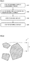
- a method of manufacturing hard alloy 10 according to the present embodiment is not particularly limited; however, the method is preferably a powder metallurgy technique including step S10 of preparing a complex carbonitride powder, step S20 of mixing the complex carbonitride powder with a metal powder, step S30 of molding the mixture, and step S40 of sintering the molded product as illustrated in Figs. 1 , 3, and 4 , from the viewpoint that hard alloy 10 is efficiently manufactured that includes complex carbonitride hard phases 11 including many homogeneous composition hard phases 11h uniform and having little variation in composition of Ti and the additional element in the phases, and that is high in hardness and fracture toughness.
- a complex carbonitride powder 1 prepared in step S10 of preparing a complex carbonitride powder is not particularly limited; however, the complex carbonitride powder preferably contains Ti as a main component element and at least one additional element selected from the group consisting of Zr, Hf, V, Nb, Ta, Cr, Mo, W, Al, and Si, from the viewpoint of efficiently manufacturing hard alloy 10 according to the present embodiment.
- Complex carbonitride powder 1 preferably includes a plurality of complex carbonitride particles 1p containing Ti and the additional element.
- the plurality of complex carbonitride particles 1p preferably include a plurality of homogeneous composition particles 1ph where in-complex carbonitride particle 1p average concentrations of Ti and the additional element have a difference in the range of greater than or equal to -5 atom% and less than or equal to 5 atom% from average concentrations of Ti and the additional element in whole complex carbonitride powder.
- a cross-sectional area of homogeneous composition particles 1ph preferably accounts for greater than or equal to 90% of a cross-sectional area of complex carbonitride particles 1p, and homogeneous composition particles 1ph preferably account for greater than or equal to 90% of complex carbonitride particles 1p in number.
- Ti contained in complex carbonitride powder 1 is a main component element, and the average concentration of Ti is greater than 50 atom% relative to the total of Ti and the additional element. Further, the average concentration of Ti is preferably greater than or equal to 60 atom% and less than or equal to 95 atom%, more preferably greater than or equal to 75 atom% and less than or equal to 90 atom%, from the viewpoint that the addition amount of the additional element is set to less than or equal to a solid solubility limit and an effect of the additional element is sufficiently drawn.
- the additional element contained in complex carbonitride powder 1 is at least one element selected from the group consisting of Zr, Hf, V, Nb, Ta, Cr, Mo, W, Al, and Si, and the average concentration of the additional element is less than 50 atom% relative to the total of Ti and the additional element.
- the average concentration of the additional element is preferably greater than or equal to 5 atom% and less than or equal to 40 atom%, more preferably greater than or equal to 10 atom% and less than or equal to 25 atom%, from the viewpoint that an effect of the additional element is sufficiently drawn and the addition amount of the additional element is set to less than or equal to a solid solubility limit.
- the identification of Ti and a type of the additional element in complex carbonitride powder 1 and complex carbonitride particles 1p and the measurement of the average concentrations of these elements are performed for a wrapped cut surface obtained by cutting a product, which is obtained through embedding of complex carbonitride powder 1 in a binder, along any specified surface together with the binder and wrapping the cut surface (that is, any cross section specified in complex carbonitride powder 1 fixed with a binder), by SEM (scanning electron microscope)/EDX (energy dispersive X-ray spectrometry) and/or EPMA (electron probe microanalyzer).
- SEM scanning electron microscope
- EDX energy dispersive X-ray spectrometry
- EPMA electron probe microanalyzer
- Suitable examples of the binder for embedding complex carbonitride powder 1 therein include an epoxy resin, a polyester resin, a phenol resin, and an acrylic resin.
- a complex carbonitride particle 1p having clear contrast in the particle is understood not to be a homogeneous composition particle without the analyses described above.
- Complex carbonitride particles 1p included in complex carbonitride powder 1 contain Ti and the additional element.
- Complex carbonitride particles 1p include a plurality of homogeneous composition particles 1ph where in-complex carbonitride particle 1p average concentrations C ⁇ Ti and C ⁇ A (atom%) of Ti and the additional element have differences C ⁇ Ti - C ⁇ Ti0 and C ⁇ A - C ⁇ A0 (atom%) in the range of greater than or equal to -5 atom% and less than or equal to 5 atom% from average concentrations C ⁇ Ti0 and C ⁇ A0 (atom%) of Ti and the additional element in whole complex carbonitride powder 1, from the viewpoint that the composition of Ti and the additional element is made uniform and small in variation (specifically to homogenize the composition) in complex carbonitride particles 1p. From the viewpoint as described above, at least one of the differences C ⁇ Ti - C ⁇ Ti0 and C ⁇ A - C ⁇ A0 is preferably greater than or equal to -3 atom% and less than or equal to 3 atom%.
- the cross-sectional area of homogeneous composition particles 1ph accounts for greater than or equal to 90% of the cross-sectional area of complex carbonitride particles 1p, and homogeneous composition particles 1ph account for greater than or equal to 90% of complex carbonitride particles 1p in number, from the viewpoint that the composition of Ti and the additional element is made uniform and small in variation (specifically to homogenize the composition) in complex carbonitride powder 1.
- the cross-sectional area of homogeneous composition particles 1ph accounts for preferably greater than or equal to 92%, more preferably greater than or equal to 94% of the cross-sectional area of complex carbonitride particles 1p.
- homogeneous composition particles 1ph account for preferably greater than or equal to 92%, more preferably greater than or equal to 94% of complex carbonitride particles 1p in number.
- a crystal particle size D 50 of complex carbonitride particles 1p at 50% in a number-based cumulative particle size distribution is preferably greater than or equal to 0.3 ⁇ m and less than or equal to 5.0 ⁇ m, from the viewpoint that the volume of the powder is reduced for easy handling and excessive pulverization of the powder that is used as a raw material powder of the hard alloy is made unnecessary, and further, the crystal particle size D 50 is more preferably greater than or equal to 0.5 ⁇ m and less than or equal to 3.0 ⁇ m, from the viewpoint of improving both the hardness and the fracture toughness of a cutting tool.
- the crystal particle size D 50 of complex carbonitride particles 1p at 50% in a number-based cumulative particle size distribution is calculated from a volume-based cumulative particle size distribution of particles measured by a laser diffraction particle size distribution analyzer.
- step S10 of preparing a complex carbonitride powder includes a mixing sub step S11 of mixing a Ti-containing oxide powder, an oxide powder containing at least one additional element selected from the group consisting of Zr, Hf, V, Nb, Ta, Cr, Mo, W, Al, and Si, and a carbon (C)-containing carbon source powder to form a mixed powder; a granulating sub step S12 of granulating the mixed powder to form granules; and a heat treatment sub step S13 of subjecting the granules to a heat treatment at a temperature of greater than or equal to 1800°C in a nitrogen gas-containing nitrogen atmosphere gas to form complex carbonitride powder 1, from the viewpoint of efficiently manufacturing complex carbonitride powder 1 that includes complex carbonitride particles 1p including homogeneous composition particles 1ph homogeneous in composition in the particles.
- the Ti-containing oxide powder, the additional element-containing oxide powder, and the C-containing carbon source powder are used as starting raw materials to substantially simultaneously and continuously cause, in heat treatment sub step S13, a reduction reaction of the oxide powders, a solid solution reaction resulting from mutual dispersion between active Ti and additional element of the reduced oxide powders, and a carbonitriding reaction of the powders that have been made into a solid solution, in particular, to remarkably promote the solid solution reaction by retention of the active Ti and additional element immediately after reduction, so that complex carbonitride powder 1 according to Embodiment 1 can be obtained that includes complex carbonitride particles 1p including homogeneous composition particles 1ph homogeneous in composition in the particles.
- the Ti-containing oxide used as a starting raw material in mixing sub step S11 is not particularly limited, and examples of the Ti-containing oxide include TiO 2 .
- a crystal structure of TiO 2 is not particularly limited and may be any of a rutile type, an anatase type, and a brookite type.
- the additional element-containing oxide is not particularly limited, and examples thereof include oxide powders of Zr, Hf, V, Nb, Ta, Cr, Mo, W, Al, and Si, namely, ZrO 2 , HfO 2 , V 2 O 5 , Nb 2 O 5 , Ta 2 O 5 , Cr 2 O 3 , MoO 3 , WO 3 , Al 2 O 3 , and SiO 2 , respectively.
- the oxidation number of each element and a content of impurities can be changed as long as the change is not against the object.
- the C-containing carbon source is not particularly limited, and graphite and polysaccharides can be also used, for example.
- the Ti-containing oxide and the additional element-containing oxide is preferably a complex oxide containing Ti and the additional element.
- the composition in complex carbonitride particles 1p can be homogenized while the powder particle size of complex carbonitride particles 1p in complex carbonitride powder 1 is kept small at 50% in a number-based cumulative particle size distribution.
- the complex oxide containing Ti and the additional element is not particularly limited, and examples of the complex oxide include Ti 0.9 Zr 0.1 O 2 and Ti 0.9 W 0.1 O 2 .
- the mixing method in mixing sub step S11 is not particularly limited; however, suitable examples of the mixing method include mixing by a dry ball mill and mixing by a wet ball mill that have a high pulverization action, from the viewpoint of reducing the powder particle size of the mixed powder (referring to the powder obtained through mixture of powders, the same applies hereinafter) at 50% in a number-based cumulative particle size distribution.
- suitable examples of the mixing method include mixing by a dry ball mill and mixing by a wet ball mill that have a high pulverization action, from the viewpoint of reducing the powder particle size of the mixed powder (referring to the powder obtained through mixture of powders, the same applies hereinafter) at 50% in a number-based cumulative particle size distribution.
- mixing with use of, for example, a rotary blade fluidized mixer having a low pulverization action can be applied if primary particles of the starting raw materials have a powder particle size of less than or equal to 0.5 ⁇ m at 50% in a number-based cumulative particle size distribution and aggregation of secondary particles
- the powder particle size of the mixed powder (referring to the power obtained through mixture of powders, the same applies hereinafter) at 50% in a number-based cumulative particle size distribution can be measured by calculating, with image analysis software, an equivalent circle diameter from an external observation image obtained by an SEM (scanning electron microscope).
- the granulating method in granulating sub step S12 is not particularly limited, and applicable examples of the granulating method include use of known devices such as a spray drier and an extrusion granulation machine.
- binder components such as a wax material may be appropriately used as a binder material.
- the shape and dimension of the granules are not particularly limited.
- the granules can be made as a circular column shape having a diameter of 0.5 mm to 5.0 mm and a length of about 5 mm to 20 mm.
- oxygen (O) in the Ti-containing oxide powder and the additional element-containing oxide powder first reacts with carbon (C) in the carbon source powder to cause a reduction reaction where the oxide powders are reduced to provide Ti and the additional element.
- C carbon
- Ti and the additional element in the oxide powders, which have been provided through the reduction, are in a state of being likely to cause a solid solution reaction where Ti and the additional element are made into a solid solution by mutual dispersion.
- Ti and the additional element in the oxide powders which have been provided through the reduction, cause a carbonitriding reaction of reacting with nitrogen (N) in the nitrogen atmosphere gas and C in the carbon source powder almost at the same time as the solid solution reaction proceeds, to form complex carbonitride powder 1 that includes complex carbonitride particles 1p including homogeneous composition particles that contain Ti and the additional element in homogeneous composition.
- metal powders specifically, a Ti-containing metal powder and an additional element-containing metal powder
- carbonitride powders specifically, a Ti-containing carbonitride powder and an additional element-containing carbonitride powder
- a complex carbonitride powder that includes complex carbonitride particles including many homogeneous composition particles homogeneous in composition in the particles.
- the reason why such a complex carbonitride powder cannot be obtained when the metal powders are used as starting raw materials is that the heat treatment causes the carbonitriding reaction earlier, so that the solid solution reaction resulting from mutual dispersion between Ti and the additional element does not proceed.
- the atmosphere in the heat treatment of heat treatment sub step S13 is a nitrogen gas (N 2 gas)-containing nitrogen atmosphere gas, from the viewpoint of forming the complex carbonitride powder from the oxide powders together with the carbon source powder.
- the nitrogen atmosphere gas may be a pure N 2 gas or a mixed gas obtained by mixing a N 2 gas with a hydrogen gas (H 2 gas), an argon gas (Ar gas), a helium gas (He gas), or a carbon monoxide gas (CO gas).
- a temperature in the heat treatment of heat treatment sub step S13 is greater than or equal to 1800°C, preferably greater than or equal to 2000°C, from the viewpoint of allowing the reduction reaction, the solid solution reaction, and the carbonitriding reaction of the oxide powders to proceed and promoting these reactions.
- the temperature needs to be greater than or equal to 1800°C from the viewpoint of sufficiently reducing, forming a solid solution from, and carbonitriding the Ti-containing oxide powder, and the temperature is preferably greater than or equal to 2000°C from the viewpoint of sufficiently reducing, forming a solid solution from, and carbonitriding an oxide powder containing Al, Zr, and/or Hf as the additional element.
- the temperature is preferably less than or equal to 2400°C from the viewpoint of preventing excessive aggregation of fired powders.
- a heat treatment time in heat treatment sub step S13 varies according to the powder particle size of the mixed powder of the oxide powders and the carbon source powder as starting raw materials at 50% in a number-based cumulative particle size distribution.
- the time is suitably about 15 minutes to 60 minutes.
- a rotary continuous heat treatment device 100 such as a rotary kiln is used in heat treatment sub step S13.
- An inclined rotary reaction tube 110 is heated to greater than or equal to 1800°C, a nitrogen atmosphere gas is flown through rotary reaction tube 110, granules are continuously supplied from an upper portion of rotary reaction tube 110, and rotary reaction tube 110 is rotated, to perform a heat treatment while the granules move in rotary reaction tube 110, so that complex carbonitride powder 1 is formed and can be extracted from a lower portion of rotary reaction tube 110.
- Such a method of manufacturing complex carbonitride powder 1 can continuously and efficiently give stable-quality complex carbonitride powder 1 according to Embodiment 1 that includes complex carbonitride particles 1p including many homogeneous composition particles 1ph homogeneous in composition in the particles.
- Heat treatment device 100 illustrated in Fig. 6 includes rotary reaction tube 110 that rotates around a long axis and is cylindrical; a rotary mechanism 120 for rotating rotary reaction tube 110; a heating mechanism 130 for heating rotary reaction tube 110; and a casing 140 that stores the heating mechanism.
- Rotary reaction tube 110 is provided with a gas inlet 110i for introducing the nitrogen atmosphere gas into rotary reaction tube 110; a gas outlet 110e for discharging the nitrogen atmosphere gas from rotary reaction tube 110; a raw material inlet 110s for charging starting raw materials into rotary reaction tube 110; and a heat-treated product outlet 110t for extracting the complex carbonitride powder as a heat treated product from rotary reaction tube 110.
- Rotary reaction tube 110 rotates around the long axis.
- gas inlet 110i is provided in the lower portion of rotary reaction tube 110 while gas outlet 110e is provided in the upper portion of rotary reaction tube 110 to give a configuration where the nitrogen atmosphere gas passes from the lower portion toward the upper portion of rotary reaction tube 110.
- the configuration may be the other way around so that the nitrogen atmosphere gas passes from the upper portion toward the lower portion of rotary reaction tube 110.
- heat treatment device 100 illustrated in Fig. 6 operates as follows.
- Rotary reaction tube 110 is heated in advance to greater than or equal to 1800°C by heating mechanism 130 of heat treatment device 100, while the nitrogen atmosphere gas is introduced into rotary reaction tube 110 from gas inlet 110i.
- Rotary reaction tube 110 is heated to a predetermined heat treatment temperature of greater than or equal to 1800°C, and then granules are supplied from raw material inlet 110s into rotary reaction tube 110 while rotary reaction tube 110 is rotated by rotary mechanism 120.
- the granules that have been supplied into rotary reaction tube 110 move from the upper portion toward the lower portion of rotary reaction tube 110 through rotary reaction tube 110 by rotation of rotary reaction tube 110 while heated to the above-mentioned heat treatment temperature by heat transferred from an inner wall of rotary reaction tube 110 and radiant heat.
- a reduction reaction of the oxide powders (the Ti-containing oxide powder and the additional element-containing oxide powder (including the cases where at least a part of the oxide powders is a complex oxide powder containing Ti and the additional element) in the granules.
- Active Ti and additional element in the oxide powders which have been provided through the reduction, promote formation of a solid solution by mutual dispersion between Ti and the additional element.
- Ti and the additional element react with nitrogen (N) supplied from the gas inlet and carbon (C) in the carbon source powder in the granules, so that a carbonitriding reaction proceeds almost at the same time as the formation of a solid solution.
- the thus carbonitrided granules reach the lower portion of rotary reaction tube 110 and are extracted from heat-treated product outlet 110t provided in the lower portion.
- the extracted granules are pulverized by a known pulverizing method appropriately selected by a person skilled in the art to give a complex carbonitride powder.
- Heat treatment device 100 having the configuration described above can substantially fix heat treatment conditions (heat treatment atmosphere, heat treatment temperature, and heat treatment time) for granules to continuously and efficiently manufacture a complex carbonitride powder stable in quality.
- step S20 of mixing the complex carbonitride powder with a metal powder is not particularly limited and can be appropriately selected according to an object of a person skilled in the art. There can be applied, for example, mixing by a dry ball mill and mixing by a wet ball mill that have a high pulverization action, or mixing with use of a rotary blade fluidized mixer or the like having a low pulverization action if aggregation of the powders is weak.
- step S30 of molding a mixture is not particularly limited; however, it is preferable to fill a mold with a mixed powder and mold the mixed powder into a predetermined shape under a predetermined pressure.
- the molding method include dry pressure molding, cold isostatic molding, injection molding, and extrusion molding.
- the pressure during the molding is preferably greater than or equal to about 0.5 ton weight/cm 2 (about 50 MPa) and less than or equal to about 2.0 ton weight/cm 2 (about 200 Mpa).
- a shape of a compact is appropriately selected according to the shape of a desired product so as to avoid an excessively complicated shape.
- the compact may be formed into a final form by appropriate machine processing required as necessary after calcining or sintering.
- the sintering method in step S40 of sintering a compact is suitably performed by retaining the compact in a temperature range where a liquid phase occurs, for a predetermined time.
- a sintering temperature is, for example, greater than or equal to about 1300°C and less than or equal to about 1600°C.
- An excessively high sintering temperature helps growth of particles constituting a hard phase.
- a retention time is greater than or equal to about 0.5 hours and less than or equal to about 2.0 hours, preferably greater than or equal to about 1.0 hour and less than or equal to about 1.5 hours, in particular.
- An atmosphere during heating is preferably an inert gas atmosphere of, for example, nitrogen or argon, or a vacuum (less than or equal to about 0.5 Pa).
- complex carbonitride powder 1 that includes complex carbonitride particles 1p including many homogeneous composition particles 1ph homogeneous in composition of Ti and the additional element in the particles, as illustrated in Fig. 4 , can efficiently give hard alloy 10 according to the present embodiment that includes complex carbonitride hard phases 11 including many homogeneous composition hard phases 11h homogeneous in composition of Ti and the additional element in the phases, as illustrated in Fig. 1 , and that is high both in hardness and fracture toughness.
- a conventional complex carbonitride powder that includes conventional complex carbonitride particles hardly including homogeneous composition particles causes a dissolution reprecipitation reaction during sintering of a compact, forming in complex carbonitride hard phases 11 many core structures that include a core phase 11p or 11q, and a peripheral phase 11s that are different from each other in composition of Ti and the additional element, as illustrated in Fig. 2 , so that the hard alloy according to the present embodiment cannot be obtained that includes complex carbonitride hard phases including many homogeneous composition hard phases.
- a cutting tool according to Embodiment 2 includes a base material formed of the hard alloy according to Embodiment 1.
- the cutting tool according to the present embodiment includes a base material formed of the hard alloy according to Embodiment 1 that is high in both hardness and fracture toughness, so that both the wear resistance and the chipping resistance are high.
- the cutting tool according to the present embodiment can further include a hard film formed on at least a part of a surface of the base material. Such a cutting tool further includes the hard film, so that both the wear resistance and the chipping resistance are high.
- the cutting tool according to the present embodiment can include the base material formed of the hard alloy according to Embodiment 1 and a hard film formed on at least a part of a surface of the base material by physical vapor deposition (PVD).
- PVD physical vapor deposition
- Such a cutting tool includes the hard film formed on at least a part of the surface of the hard alloy by PVD, so that both the wear resistance and the chipping resistance are high.
- the PVD include resistive heating vapor deposition, electron beam (EB) vapor deposition, molecular beam epitaxy (MBE), ion plating, ion beam deposition, and sputtering.
- the cutting tool according to the present embodiment can include the base material formed of, among the hard alloys according to the embodiments described above, the hard alloy where the content of an iron group element except cobalt (Co) in the metal binder phase is less than 1 vol%, and a hard film formed on at least a part of the surface of the base material by chemical vapor deposition (CVD).
- the content of an iron group element except Co in the metal binder phase of the hard alloy that forms the base material is less than 1 vol%, that is, the content of nickel (Ni) is less than 1 vol%, so that the hard film can be formed on at least a part of the surface of the base material by CVD without forming a harmful phase that deteriorates the characteristics of the base material.
- Representative hard films obtained by such CVD e.g., an Al 2 O 3 film, a TiCN film, and a TiN film have the same or an approximate linear thermal expansion coefficient to that of the hard alloy, so that the generation of thermal cracking can be suppressed in such a hard film. That is, in such a cutting tool, the hard film can be formed on at least a part of the surface of the base material by chemical vapor deposition without forming a harmful phase, both the wear resistance and the chipping resistance are high, and the generation of thermal cracking can be suppressed.
- examples of the CVD include thermal CVD, plasma CVD, and MOCVD (metal organic chemical vapor deposition).
- Examples 1 to 10 are examples relating to the hard alloy according to Embodiment 1. As described below, hard alloys were produced by a powder metallurgy technique.
- oxide powders namely a TiO 2 powder and an additional element oxide (ZrO 2 , HfO 2 , V 2 O 5 , Nb 2 O 5 , Ta 2 O 5 , Cr 2 O 3 , MoO 3 , WO 3 , Al 2 O 3 , and SiO 2 ) powder and a carbon source powder, namely a graphite powder were mixed in blending ratios so as to have designed composition shown in Examples 1 to 10 of Table 1.
- the mixing was performed by a ball-mill method.
- a powder particle size of the obtained mixed powder at 50% in a number-based cumulative particle size distribution was measured by calculating, with image analysis software, an equivalent circle diameter from an external photograph obtained by an SEM. The results are shown in Table 1.
- the mixed powder was formed into circular column-shaped granules having an average diameter of 2.4 mm and an average length of about 10 mm by a known extrusion granulation machine (hole diameter: ⁇ 2.5 mm).
- an average diameter and an average length of the granules were measured by a micrometer.
- the granules were subjected to a heat treatment by a heat treatment device 100 illustrated in Fig. 6 , namely a rotary kiln in an atmosphere of a nitrogen gas as a nitrogen atmosphere gas at a heat treatment temperature shown in Table 1 to give a complex carbonitride powder.
- the granules passed a heating zone with a passing time of about 30 minutes.
- the obtained complex carbonitride powder was subjected to measurement through SEM/EDX and EPMA for a wrapped cut surface obtained by embedding complex carbonitride powder 1 in a resin, cutting the powder together with the resin, and wrapping the cut surface, to obtain a percentage of a cross-sectional area of homogeneous composition particles 1ph to a cross-sectional area of complex carbonitride particles 1p and a percentage of the number of homogeneous composition particles 1ph to the number of complex carbonitride particles 1p, in the obtained complex carbonitride powder.
- Table 1 The results are shown in Table 1.
- the complex carbonitride powder obtained as described above was mixed with a Co powder and a Ni powder as metal powders in blending ratios so as to have designed composition shown in Examples 1 to 10 of Table 2 by a ball mill for 5 hours to give a mixture.
- the obtained mixture was formed into granules with camphor and ethanol and subjected to press molding at a pressure of 1 ton weight/cm 2 (about 98 MPa) to give a compact.
- the obtained compact was subjected to liquid phase sintering in a vacuum (0.1 Pa) atmosphere under the conditions of a maximum temperature of 1410°C and a retention time of 1 hour to give a hard alloy as a sintered body.
- the obtained hard alloy was subjected to measurement through SEM/EDX (STEM (scanning transmission electron microscope)/EDX in the cases where crystals in the hard alloy had a fine particle size) and EPMA for a wrapped cut surface obtained by cutting the hard alloy and wrapping the cut surface, to obtain, on any cross section specified in the obtained hard alloy, a percentage of a cross-sectional area of homogeneous composition hard phases to a cross-sectional area of complex carbonitride hard phases and a percentage of the number of homogeneous composition hard phases to the number of complex carbonitride hard phases.
- the hard alloy was subjected to measurement by a Vickers indentation method for the cut surface of the hard alloy that had been mirror-finished, to obtain the hardness and the fracture toughness of the hard alloy.
- the hard alloy was subjected to measurement by SEM/EBSD (electron backscatter diffraction) for the cut surface of the hard alloy that had been mirror-finished, to obtain crystal particle sizes D 50 , D 10 , and D 90 at 50%, 10%, and 90% in a number-based cumulative particle size distribution, and a ratio D 10 /D 90 of the crystal particle size D 10 at 10% in a number-based cumulative particle size distribution to the crystal particle size D 90 at 90% in a number-based cumulative particle size distribution.
- SEM/EBSD electron backscatter diffraction
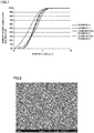
- FIG. 7 illustrates the results of analyzing the hard alloys of Examples 2 and 3 in terms of the number-based cumulative crystal particle size distributions obtained by SEM/EBSD.
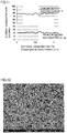
- Fig. 8 illustrates an SEM photograph of a cross-sectional structure of the hard alloy in Example 3.
- Example Designed composition vol%) Complex carbonitride hard phases Ratio D 10 /D 90 Hardness (GPa) Fracture toughness (MPa•m 0.5 ) Homogeneous composition phases
- Phase size D 50 ( ⁇ m) at 50% in number-based cumulative phase size distribution Percentage of cross-sectional area (%) Percentage of number of particles (%) 1 84(Ti 0.75 W 0.25 )CN-8Co-8Ni 82.4 84 0.8 0.30 14.3 8.5 2 88(Ti 0.77 Mo 0.23 )CN-6Co-6Ni 94.4 98 0.6 0.29 14.8 8.3 3 90(Ti 0.85 Nb 0.15 )CN-5Co-5Ni 94.2 94 1.2 0.32 13.2 8.7 4 90(
- both the hardness and the fracture toughness were high in the hard alloys that were produced with use of a complex carbonitride powder including complex carbonitride particles including many homogeneous composition particles homogeneous in composition in the particles and that included complex carbonitride hard phases including many homogeneous composition hard phases homogeneous in composition in the phases.
- Example 2 was subjected to SEM/EDX analysis in terms of a composition distribution in a complex carbonitride hard phase.
- the results are shown in Table 9.
- the analysis was performed for a range of about 0.5 ⁇ m from the center to an end portion of a hard phase using as a target a complex carbonitride hard phase that had a relatively large particle size, a diameter of about 1.1 ⁇ m in terms of a circle having an area equivalent to that of the phase, in the hard alloy.
- the average concentrations of Ti and Mo in all the complex carbonitride hard phases, which were obtained by SEM/EDX analysis were 77.6 atom% and 22.2 atom%, respectively, with the balance being inevitable impurities.
- the complex carbonitride hard phase of the present example were so uniform to have a composition distribution of Ti within 77.6 atom% ⁇ 5 atom% and a composition distribution of the additional element Mo within 22.2 atom% ⁇ 5 atom%.
- the hard alloy was high in both hardness and fracture toughness.
- the hard alloy of Example 3 was subjected to STEM/EDX analysis in terms of a composition distribution in a complex carbonitride hard phase.
- the analysis was performed for a thin film sample taken from a cross section of the hard alloy with use of FIB (focused ion beam), in a range from one end (one side end portion) indicated by an arrow to the other end (the other side end portion) on a complex carbonitride hard phase in Fig. 10 .
- the results are shown in Fig. 11 .
- the average concentrations of Ti and Nb in all the complex carbonitride hard phases, which were obtained by STEM/EDX analysis were 78.2 atom% and 21.2 atom%, respectively, with the balance being inevitable impurities.
- Fig. 11 the average concentrations of Ti and Nb in all the complex carbonitride hard phases, which were obtained by STEM/EDX analysis, were 78.2 atom% and 21.2 atom%, respectively, with the balance being inevitable impurities.
- the complex carbonitride hard phases of the present example were so uniform to have a composition distribution of Ti within 78.2 atom% ⁇ 5 atom% and a composition distribution of the additional element Nb within 21.2 atom% ⁇ 5 atom%.
- the hard alloy was high in both hardness and fracture toughness.
- Hard alloys of Comparative Examples 1 to 3 were obtained in the same manner as in Examples 1 to 3 by a powder metallurgy technique except for using, in place of the complex carbonitride powder, a TiCN powder having a powder particle size of 0.8 ⁇ m at 50% in a number-based cumulative particle size distribution and a WC powder having a powder particle size of 1.1 ⁇ m at 50% in a number-based cumulative particle size distribution, a Mo 2 C powder having a powder particle size of 2.0 ⁇ m at 50% in a number-based cumulative particle size distribution, or a NbC powder having a powder particle size of 0.8 ⁇ m at 50% in a number-based cumulative particle size distribution.
- the obtained hard alloys were subjected to measurement in the same manner as in Example 1 to obtain, on any cross section specified in the obtained hard alloys, a percentage of a cross-sectional area of homogeneous composition hard phases to a cross-sectional area of complex carbonitride hard phases, a percentage of the number of homogeneous composition hard phases to the number of complex carbonitride hard phases, the hardness and the fracture toughness of the hard alloy, crystal particle sizes D 50 , D 10 , and D 90 at 50%, 10%, and 90% in a number-based cumulative particle size distribution, and a ratio D 10 /D 90 of the crystal particle size D 10 at 10% in a number-based cumulative particle size distribution to the crystal particle size D 90 at 90% in a number-based cumulative particle size distribution.
- Fig. 7 illustrates the results of analyzing the hard alloys of Comparative Examples 2 and 3 in terms of the number-based cumulative crystal particle size distributions obtained by SEM/EBSD.
- Fig. 12 illustrates an SEM photograph of a cross-sectional structure of the hard alloy in Comparative Example 3.
- the hard alloys produced with use of the TiCN powder and each of the additional element carbide powders that formed the complex carbonitride hard phases and the metal powders that formed a metal binder phase included complex carbonitride hard phases that hardly included homogeneous composition hard phases homogeneous in composition in the phases, and were low in fracture toughness even though the hardness was high.
- the hard alloy of Comparative Example 2 was subjected to SEM/EDX analysis in terms of a composition distribution in a complex carbonitride hard phase.
- the results are shown in Fig. 13 .
- the analysis was performed in the same manner as in Example 2 for a range of about 0.5 ⁇ m from the center to an end portion of a hard phase using as a target a complex carbonitride hard phase that had a relatively large particle size, a diameter of about 1.1 ⁇ m in terms of a circle having an area equivalent to that of the phase, in the hard alloy.
- the average concentrations of Ti and Mo in all the hard phases, which were obtained by SEM/EDX analysis were 77.4 atom% and 21.8 atom%, respectively, with the balance being inevitable impurities.
- the complex carbonitride hard phases of the present comparative example were ununiform in composition distributions of Ti and the additional element Mo.
- the hard alloy was low in fracture toughness even though the hardness was high.
- the hard alloy of Comparative Example 3 was subjected to STEM/EDX analysis in terms of a composition distribution in a complex carbonitride hard phase.
- Fig. 15 shows STEM/EDX analysis results for a range from one end (one side end portion) indicated by an arrow to the other end (the other side end portion) on the complex carbonitride hard phase in Fig. 14 .
- the average concentrations of Ti and Nb in all the complex carbonitride hard phases, which were obtained by STEM/EDX analysis were 78.6 atom% and 21.0 atom%, respectively, with the balance being inevitable impurities.
- the complex carbonitride hard phases of the present comparative example were ununiform in composition distributions of Ti and the additional element Nb. Thus, it was understood that the hard alloy was low in fracture toughness even though the hardness was high.
- Examples 11 to 13 are examples relating to the cutting tool according to Embodiment 2. As described below, cutting tools were produced.
- Base materials were produced that had a CNMA120404 shape with use of the hard alloys of Examples 1 to 3.
- the base materials were not ground for a flank face and a rake face.
- the base materials were subjected to cutting edge processing.
- a TiAIN film having a thickness of 5 ⁇ m was formed as a hard film by PVD, namely sputtering.
- cutting tools of Examples 11 to 13 were obtained that included the base materials produced with use of the hard alloys of Examples 1 to 3, respectively.
- the wear resistance was high while the chipping resistance was low in the cutting tools each including the base material that was produced with use of the hard alloy that included complex carbonitride hard phases hardly including homogeneous composition hard phases homogeneous in composition in the phases.
- Examples 21 to 23 are examples relating to the hard alloy according to Embodiment 1. Mixtures obtained by mixing the same carbonitride powders of Examples 1 to 3 with a cobalt powder were subjected to press molding and liquid phase sintering under the same conditions as in Examples 1 to 3 to produce SNGN120408-shaped hard alloys.
- the hard alloys were subjected to measurement in the same method as in Examples 1 to 3 to obtain crystal particle sizes D 50 , D 10 , and D 90 of complex carbonitride hard phases at 50%, 10%, and 90% in a number-based cumulative particle size distribution, a ratio D 10 /D 90 of the crystal particle size D 10 at 10% in a number-based cumulative particle size distribution to the crystal particle size D 90 at 90% in a number-based cumulative particle size distribution.
- Table 7 The results are shown in Table 7.
- Hard alloys of Comparative Examples 21 to 23 were obtained in the same manner as in Examples 21 to 23 except for using, in place of the complex carbonitride powder, a TiCN powder having a particle size of 0.8 ⁇ m at 50% in a number-based cumulative particle size distribution and a WC powder having a particle size of 1.1 ⁇ m at 50% in a number-based cumulative particle size distribution, a Mo 2 C powder having a particle size of 2.0 ⁇ m at 50% in a number-based cumulative particle size distribution, or a NbC powder having a particle size of 0.8 ⁇ m at 50% in a number-based cumulative particle size distribution.
- the evaluation results of these hard alloys are shown in Table 8.
- the hard alloys that did not include the complex carbonitride powder were not excellent in both hardness and fracture toughness even though cobalt was used as the metal binder phase. It is considered that the complex carbonitride powder is excellent in sinterability with cobalt, while the carbonitride powders of Comparative Examples 21 to 23 are inferior in sinterability with cobalt, so that sintering cavities are formed in the hard alloys to deteriorate the characteristics.
- the hard alloys of Examples 21 to 23 as base materials were subjected to a known thermal CVD process to form coating of a TiC film on the base materials, thus preparing CNMA120404-shaped surface-coated cutting tools.
- the type of a gas was a mixed gas of TiCl 4 , H 2 , and CH 4
- a film forming pressure was 0.01 MPa
- a film-forming temperature was 1000°C
- a film-forming time was 1 hour.
- the presence or absence of a harmful phase was confirmed for a rake face-end flat portion by XRD (X-ray diffraction). Specifically, the harmful phase was determined to be present when a clear peak derived from Ni 3 Ti and/or NiTi was detected by XRD, and the harmful phase was determined to be absent when peak strength derived from Ni 3 Ti and NiTi was less than or equal to a background level.
- XRD X-ray diffraction
- the cutting tools of Examples 31 to 33 had no harmful phase formed in the coating of the TiC film, and the number of cracks were very small. Therefore, the cutting tools can be expected to be cutting tools excellent in both wear resistance and chipping resistance.
- 1 Complex carbonitride powder 1p Complex carbonitride particle, 1ph Homogeneous composition particle, 10 Hard alloy, 11 Complex carbonitride hard phase, 11h Homogeneous composition hard phase, 11o Single phase, 11p, 11q Core phase, 11s Peripheral phase, 12 Metal binder phase, 100 Heat treatment device, 110 Rotary reaction tube, 110e Gas outlet, 110i Gas inlet, 110s Raw material inlet, 110t Heat-treated product outlet, 120 Rotary mechanism, 130 Heating mechanism, 140 Casing, S10 Step of preparing complex carbonitride powder, S11 Mixing sub step, S12 Granulating sub step, S13 Heat treatment sub step, S20 Step of mixing complex carbonitride powder with metal powder, S30 Step of molding mixture, S40 Step of sintering molded product.
Landscapes
- Chemical & Material Sciences (AREA)
- Organic Chemistry (AREA)
- Engineering & Computer Science (AREA)
- Mechanical Engineering (AREA)
- Materials Engineering (AREA)
- Metallurgy (AREA)
- Inorganic Chemistry (AREA)
- Manufacturing & Machinery (AREA)
- Powder Metallurgy (AREA)
- Cutting Tools, Boring Holders, And Turrets (AREA)
Abstract
Description
- The present invention relates to a hard alloy and a cutting tool. The present application claims priority based on Japanese Patent Application No.
2015-215726 filed on November 2, 2015 - A cermet that is a hard alloy containing Ti as a main component element is excellent in wear resistance and therefore has been suitably used for, for example, cutting tools and wear resistance tools.
- Japanese Patent Laying-Open No.
02-190438 - Japanese Patent Laying-Open No.
2004-292842 - Japanese Patent Laying-Open No.
2006-131975 -
WO 2010/008004 A (PTD 4) discloses a hard powder containing greater than or equal to 90 vol% of a complex carbonitride solid solution represented by (Ti1-x,Mx)(C1-y,Ny), a method of manufacturing the hard powder, and a sintered hard alloy consisting of a hard phase that contains the complex carbonitride solid solution represented by (Ti1-x,Mx)(C1-y,Ny) in an amount of greater than or equal to 90 vol% of the whole hard phase, and a binder phase. -
- PTD 1: Japanese Patent Laying-Open No.
02-190438 - PTD 2: Japanese Patent Laying-Open No.
2004-292842 - PTD 3: Japanese Patent Laying-Open No.
2006-131975 - PTD 4:
WO 2010/008004 A - A hard alloy according to the present disclosure includes a plurality of complex carbonitride hard phases that contain titanium as a main component element and at least one additional element selected from the group consisting of zirconium, hafnium, vanadium, niobium, tantalum, chromium, molybdenum, tungsten, aluminum, and silicon, and a metal binder phase containing an iron group element as a main component element. The plurality of complex carbonitride hard phases include a plurality of homogeneous composition hard phases where in-complex carbonitride hard phase average concentrations of titanium and the additional element have a difference in the range of greater than or equal to -5 atom% and less than or equal to 5 atom% from average concentrations of titanium and the additional element in all the complex carbonitride hard phases. On any cross section specified in the hard alloy, a cross-sectional area of the homogeneous composition hard phases accounts for greater than or equal to 80% of a cross-sectional area of the complex carbonitride hard phases, and the homogeneous composition hard phases account for greater than or equal to 80% of the complex carbonitride hard phases in number.
- A cutting tool according to the present disclosure includes a base material formed of the hard alloy described above.
-
-
Fig. 1 is a schematic view illustrating one example of a cross-sectional structure of a hard alloy according to an aspect of the present invention. -
Fig. 2 is a schematic view illustrating one example of a cross-sectional structure of a conventional hard alloy. -
Fig. 3 is a flow chart illustrating one example of a method of manufacturing a hard alloy according to an aspect of the present invention. -
Fig. 4 is a schematic view illustrating one example of a cross-sectional structure of a complex carbonitride powder used for manufacturing a hard alloy according to an aspect of the present invention. -
Fig. 5 is a flow chart illustrating one example of a step of preparing a complex carbonitride powder used for manufacturing a hard alloy according to an aspect of the present invention. -
Fig. 6 is a schematic view illustrating one example of a heat treatment device used in the step of preparing a complex carbonitride powder used for manufacturing a hard alloy according to an aspect of the present invention. -
Fig. 7 is a graph of number-based cumulative crystal particle size distributions for complex carbonitride hard phases in hard alloys of Examples 2 and 3 and Comparative Examples 2 and 3. -
Fig. 8 is a scanning electron micrograph illustrating a cross-sectional structure of the hard alloy in Example 3. -
Fig. 9 is a graph illustrating concentration distributions of titanium and an additional element in a homogeneous composition hard phase of the complex carbonitride hard phases in the hard alloy of Example 2. -
Fig. 10 is a scanning transmission electron micrograph illustrating a cross-sectional structure of the hard alloy in Example 3. -
Fig. 11 is a graph illustrating concentration distributions of titanium and an additional element in a homogeneous composition hard phase of the complex carbonitride hard phases in the hard alloy of Example 3. -
Fig. 12 is a scanning electron micrograph illustrating a cross-sectional structure of the hard alloy in Comparative Example 3. -
Fig. 13 is a graph illustrating concentration distributions of titanium and an additional element in a homogeneous composition hard phase of the complex carbonitride hard phases in the hard alloy of Comparative Example 2. -
Fig. 14 is a scanning transmission electron micrograph illustrating a cross-sectional structure of the hard alloy in Comparative Example 3. -
Fig. 15 is a graph illustrating concentration distributions of titanium and an additional element in a homogeneous composition hard phase of the complex carbonitride hard phases in the hard alloy of Comparative Example 3. - All the cermets disclosed in Japanese Patent Laying-Open No.
02-190438 2004-292842 2006-131975 -
WO 2010/0080004 A WO 2010/0080004 A - Therefore, an object of the present invention is to solve the problems described above and provide a hard alloy that includes a complex carbonitride hard phase having homogeneous composition and that is high in hardness and fracture toughness and provide a cutting tool high in wear resistance and chipping resistance.
- According to the present disclosure, it is possible to provide a hard alloy that includes a complex carbonitride hard phase having homogeneous composition and that is high in hardness and fracture toughness and provide a cutting tool high in wear resistance and chipping resistance
-
- [1] A hard alloy according to an embodiment of the present invention includes a plurality of complex carbonitride hard phases that contain titanium as a main component element and at least one additional element selected from the group consisting of zirconium, hafnium, vanadium, niobium, tantalum, chromium, molybdenum, tungsten, aluminum, and silicon, and a metal binder phase containing an iron group element as a main component element. The plurality of complex carbonitride hard phases include a plurality of homogeneous composition hard phases where in-complex carbonitride hard phase average concentrations of titanium and the additional element have a difference in a range of greater than or equal to -5 atom% and less than or equal to 5 atom% from average concentrations of titanium and the additional element in all the complex carbonitride hard phases. On any cross section specified in the hard alloy, a cross-sectional area of the homogeneous composition hard phases accounts for greater than or equal to 80% of a cross-sectional area of the complex carbonitride hard phases, and the homogeneous composition hard phases account for greater than or equal to 80% of the complex carbonitride hard phases in number. Many of the complex carbonitride hard phases included in the hard alloy according to the present embodiment are homogeneous composition hard phases that are uniform and have little variation in composition of titanium and the additional element with respect to all the complex carbonitride hard phases, so that the hard alloy is high in both hardness and fracture toughness.
- [2] In the homogeneous composition hard phases of the hard alloy according to the present embodiment, concentration distributions of titanium and the additional element in each of the homogeneous composition hard phases can be set to a range of greater than or equal to -5 atom% and less than or equal to 5 atom% from the average concentrations of titanium and the additional element in all the complex carbonitride hard phases. Such a hard alloy has small concentration distributions of titanium and the additional element in each of the homogeneous composition hard phases, that is, the composition of titanium and the additional element in each of the homogeneous composition hard phases is uniform and has little variation, so that both the hardness and the fracture toughness are high.
- [3] On a cross section specified in the hard alloy according to the present embodiment, the cross-sectional area of the complex carbonitride hard phases can be set to greater than or equal to 80% and less than or equal to 97% of a cross-sectional area of the hard alloy. Such a hard alloy has a suitable cross-sectional area ratio between the complex carbonitride hard phases and the metal binder phase, so that both the hardness and the fracture toughness are high.
- [4] On the cross section specified in the hard alloy according to the present embodiment, a crystal particle size D50 of the complex carbonitride hard phases at 50% in a number-based cumulative particle size distribution can be set to greater than or equal to 0.5 µm and less than or equal to 3.0 µm. Such a hard alloy is high in both hardness and fracture toughness, so that it is particularly suitably used for a cutting tool.
- [5] On the cross section specified in the hard alloy according to the present embodiment, a ratio D10/D90 of a crystal particle size D10 to a crystal particle size D90 of the complex carbonitride hard phases at 10% and 90% in a number-based cumulative particle size distribution can be set to greater than or equal to 0.25. Such a hard alloy has a sharp particle size distribution of the complex carbonitride hard phases, resulting in reduction of a coarse structure that can be an origin of fracture, so that chipping resistance is particularly high.
- [6] In the hard alloy according to the present embodiment, a content of an iron group element except cobalt in the metal binder phase can be set to less than 1 vol%. Such a hard alloy contains cobalt as a main component of the metal binder phase, so that both the hardness and the fracture toughness are high due to the characteristics of cobalt itself.
- [7] The hard alloy according to the present embodiment includes a plurality of complex carbonitride hard phases that contain titanium as a main component element and at least one additional element selected from the group consisting of zirconium, hafnium, vanadium, niobium, tantalum, chromium, molybdenum, tungsten, aluminum, and silicon, and a metal binder phase containing an iron group element as a main component element; the plurality of complex carbonitride hard phases includes a plurality of homogeneous composition hard phases where in-complex carbonitride hard phase average concentrations of titanium and the additional element have a difference in a range of greater than or equal to -5 atom% and less than or equal to 5 atom% from average concentrations of titanium and the additional element in all the complex carbonitride hard phases; in the homogeneous composition hard phases, concentration distributions of titanium and the additional element in each of the homogeneous composition hard phases are set to a range of greater than or equal to -5 atom% and less than or equal to 5 atom% from the average concentrations of titanium and the additional element in all the complex carbonitride hard phases; on any specified cross section, a cross-sectional area of the homogeneous composition hard phases accounts for greater than or equal to 80% of a cross-sectional area of the complex carbonitride hard phases, the homogeneous composition hard phases account for greater than or equal to 80% of the complex carbonitride hard phases in number, the cross-sectional area of the complex carbonitride hard phases is set to greater than or equal to 80% and less than or equal to 97% of a cross-sectional area of the hard alloy, a crystal particle size D50 of the complex carbonitride hard phases at 50% in a number-based cumulative particle size distribution is set to greater than or equal to 0.5 µm and less than or equal to 3.0, and a ratio D10/D90 of a crystal particle size D10 to a crystal particle size D90 of the complex carbonitride hard phases at 10% and 90% in a number-based cumulative particle size distribution can be set to greater than or equal to 0.25; and a content of an iron group element except cobalt in the metal binder phase can be set to less than 1 vol%. Such a hard alloy is high in both hardness and fracture toughness, so that it is particularly suitably used for a cutting tool.
- [8] A cutting tool according to another embodiment of the present invention includes a base material formed of the hard alloy according to the embodiments described above. The cutting tool according to the present embodiment includes the base material formed of the hard alloy high in both hardness and fracture toughness, so that both the wear resistance and the chipping resistance are high.
- [9] The cutting tool according to the present embodiment can further include a hard film that is formed on at least a part of a surface of the base material. Such a cutting tool further includes the hard film, so that both the wear resistance and the chipping resistance are high.
- [10] A cutting tool according to the present embodiment can include a base material formed of the hard alloy according to the embodiments described above, and a hard film that is formed on at least a part of a surface of the base material by physical vapor deposition. Such a cutting tool includes the hard film formed on at least a part of the surface of the hard alloy by physical vapor deposition, so that both the wear resistance and the chipping resistance are high.
- [11] A cutting tool according to the present embodiment can include a base material formed of, among the hard alloys according to the embodiments described above, the hard alloy where the content of an iron group element except cobalt in the metal binder phase is less than 1 mass%, and a hard film formed on at least a part of a surface of the base material by chemical vapor deposition. In such a cutting tool, the hard film can be formed on at least a part of a surface of the base material by chemical vapor deposition without forming a harmful phase, both the wear resistance and the chipping resistance are high, and a thermal expansion coefficient of the base material is approximate to that of the hard film to suppress the generation of thermal cracking after formation of the film.
- As illustrated in
Fig. 1 , ahard alloy 10 according toEmbodiment 1 includes a plurality of complex carbonitride hard phases 11 that contain titanium (Ti) as a main component element and at least one additional element selected from the group consisting of zirconium (Zr), hafnium (Hf), vanadium (V), niobium (Nb), tantalum (Ta), chromium (Cr), molybdenum (Mo), tungsten (W), aluminum (Al), and silicon (Si), and ametal binder phase 12 containing an iron group element as a main component element. The plurality of complex carbonitride hard phases 11 include a plurality of homogeneous compositionhard phases 11h where in-complex carbonitride hard phase average concentrations of Ti and the additional element have a difference in the range of greater than or equal to -5 atom% and less than or equal to 5 atom% from average concentrations of Ti and the additional element in all complex carbonitride hard phases 11. On any cross section specified inhard alloy 10, a cross-sectional area of homogeneous compositionhard phases 11h accounts for greater than or equal to 80% of a cross-sectional area of complex carbonitride hard phases 11, and homogeneous compositionhard phases 11h account for greater than or equal to 80% of complex carbonitride hard phases 11 in number. Many of complex carbonitride hard phases 11 included inhard alloy 10 according to the present embodiment are homogeneous composition hard phases 11h that are uniform and have little variation in composition of Ti and the additional element in the phases, so that the hard alloy is high in both hardness and fracture toughness. Concentration distributions of carbon (C) and nitrogen (N) in complex carbonitride hard phases 11 are not particularly limited. - Ti contained in complex carbonitride hard phases 11 is a main component element, and the average concentration of Ti is greater than 50 atom% relative to the total of Ti and the additional element. Further, the average concentration of Ti is preferably greater than or equal to 60 atom% and less than or equal to 95 atom%, more preferably greater than or equal to 75 atom% and less than or equal to 90 atom%, from the viewpoint that the addition amount of the additional element is set to less than or equal to a solid solubility limit and an effect of the additional element is sufficiently drawn.
- The additional element contained in complex carbonitride hard phases 11 is at least one element selected from the group consisting of Zr, Hf, V, Nb, Ta, Cr, Mo, W, Al, and Si, the average concentration of the additional element is less than 50 atom% relative to the total of Ti and the additional element. Further, the average concentration of the additional element is preferably greater than or equal to 5 atom% and less than or equal to 40 atom%, more preferably greater than or equal to 10 atom% and less than or equal to 25 atom%, from the viewpoint that an effect of the additional element is sufficiently drawn and the addition amount of the additional element is set to less than or equal to a solid solubility limit.
-
Metal binder phase 12 contains the iron group element as a main component element and, in addition to the iron group element, an inevitable element mixed from the complex carbonitride hard phases (i.e., at least a part of the additional element) and a slight amount of an impurity element. The average concentration of the iron group element is preferably greater than or equal to 90 atom%, more preferably greater than or equal to 95 atom%, from the viewpoint that the iron group element keeps a state of a metal and formation of a brittle intermediate compound is avoided. Here, the iron group element refers to the elements ofGroups 8, 9, and 10 in Period 4, i.e., iron (Fe), cobalt (Co), and nickel (Ni). Examples of the element other than the iron group element contained inmetal binder phase 12 include titanium (Ti) and tungsten (W). - Here, the identification of types of Ti and the additional element in complex carbonitride hard phases 11 and the iron group element and a metal element other than the iron group element in
metal binder phase 12 and the measurement of the average concentrations of these elements are performed for a wrapped cut surface obtained by cuttinghard alloy 10 along any specified surface and wrapping the cut surface, by SEM (scanning electron microscope)/EDX (energy dispersive X-ray spectroscopy) and/or EPMA (electron probe microanalyzer). In an SEM composition image of a cut surface ofhard alloy 10, a complex carbonitridehard phase 11 having clear contrast in the phase is understood not to be a homogeneous composition hard phase without the analyses described above. - The plurality of complex carbonitride hard phases 11 contain Ti and the additional element. The plurality of complex carbonitride hard phases 11 include the plurality of homogeneous composition
hard phases 11h where in-complex carbonitridehard phase 11 average concentrations CβTi and CβA (atom%) of Ti and the additional element have differences CβTi - CβTi0 and CβA - CβA0 (atom%) in the range of greater than or equal to -5 atom% and less than or equal to 5 atom% from average concentrations CβTi0 and CβA0 (atom%) of Ti and the additional element in all the plurality of complex carbonitride hard phases 11, from the viewpoint that the composition of Ti and the additional element is made uniform and small in variation (specifically to homogenize the composition) in complex carbonitride hard phases 11. From the viewpoint as described above, at least one of the differences CβTi - CβTi0 and CβA - CβA0 is preferably greater than or equal to -3 atom% and less than or equal to 3 atom%. - On any cross section specified in
hard alloy 10, the cross-sectional area of homogeneous compositionhard phases 11h accounts for greater than or equal to 80% of the cross-sectional area of complex carbonitride hard phases 11, and homogeneous compositionhard phases 11h account for greater than or equal to 80% of complex carbonitride hard phases 11 in number, from the viewpoint that the composition of Ti and the additional element of complex carbonitride hard phases 11 is made uniform and small in variation (specifically to homogenize the composition) in complex carbonitride hard phases 11. From the viewpoint as described above, the cross-sectional area of homogeneous compositionhard phases 11h accounts for preferably greater than or equal to 85%, more preferably greater than or equal to 90% of the cross-sectional area of complex carbonitride hard phases 11. In addition, homogeneous compositionhard phases 11h account for preferably greater than or equal to 85%, more preferably greater than or equal to 90% of complex carbonitride hard phases 11 in number. - In homogeneous composition
hard phases 11h ofhard alloy 10 according to the present embodiment, concentration distributions of titanium and the additional element in each of homogeneous compositionhard phases 11h are preferably in the range of greater than or equal to -5 atom% and less than or equal to 5 atom%, more preferably greater than or equal to -3 atom% and less than or equal to 3 atom% from the average concentrations of titanium and the additional element in all complex carbonitride hard phases 11. Suchhard alloy 10 has small concentration distributions of titanium and the additional element in each of homogeneous compositionhard phases 11h, that is, the composition of titanium and the additional element in each of homogeneous compositionhard phases 11h is uniform and has little variation, so that both the hardness and the fracture toughness are high. - Here, as for homogeneous composition
hard phases 11h, the phrase "a concentration distribution of titanium in each of homogeneous compositionhard phases 11h is in the range of greater than or equal to -5 atom% and less than or equal to 5 atom% or in the range of greater than or equal to -3 atom% and less than or equal to 3 atom% from the average concentration of titanium in all complex carbonitride hard phases 11" refers to that, as for a minimum concentration CβTi-Min (atom%) and a maximum concentration CβTi-Max (atom%) of titanium in each of homogeneous compositionhard phases 11h and an average concentration CβTi0 (atom%) of titanium in all complex carbonitride hard phases 11, CβTi-Min - CβTi0 is greater than or equal to -5 atom% and CβTi-Max - CβTi0 is less than or equal to 5 atom%, or CβTi-Min - CβTi0 is greater than or equal to -3 atom% and CβTi-Max - CβTi0 is less than or equal to 3 atom%. - Here, as for homogeneous composition
hard phases 11h, the phrase "a concentration distribution of the additional element in each of homogeneous compositionhard phases 11h is in the range of greater than or equal to -5 atom% and less than or equal to 5 atom% or in the range of greater than or equal to -3 atom% and less than or equal to 3 atom% from the average concentration of the additional element in all complex carbonitride hard phases 11" refers to that, as for a minimum concentration CβA-Min (atom%) and a maximum concentration CβA-Max (atom%) of the additional element in each of homogeneous compositionhard phases 11h and an average concentration CβA0 (atom%) of the additional element in all complex carbonitride hard phases 11, CβA-Min - CβA0 is greater than or equal to -5 atom% and CβA-Max - CβA0 is less than or equal to 5 atom%, or CβA-Min - CβA0 is greater than or equal to -3 atom% and CβA-Max - CβA0 is less than or equal to 3 atom%. - On the cross section specified in
hard alloy 10 according to the present embodiment, the cross-sectional area of complex carbonitride hard phases 11 accounts for preferably greater than or equal to 80% and less than or equal to 97%, more preferably greater than or equal to 84% and less than or equal to 92% of a cross-sectional area ofhard alloy 10, from the viewpoint ofhard alloy 10 high in both hardness and fracture toughness. That is, a cross-sectional area of the metal binder phase accounts for preferably greater than or equal to 3% and less than or equal to 20%, more preferably greater than or equal to 8% and less than or equal to 16% of the sectional area ofhard alloy 10. - On the cross section specified in
hard alloy 10 according to the present embodiment, a crystal particle size D50 of complex carbonitride hard phases 11 at 50% in a number-based cumulative particle size distribution is preferably greater than or equal to 0.5 µm and less than or equal to 3.0 µm, more preferably greater than or equal to 0.6 µm and less than or equal to 2.0 µm, from the viewpoint ofhard alloy 10 high in both hardness and high fracture toughness. - On the cross section specified in
hard alloy 10 according to the present embodiment, a ratio D10/D90 of a crystal particle size D10 to a crystal particle size D90 of complex carbonitride hard phases 11 at 10% and 90% in a number-based cumulative particle size distribution is preferably greater than or equal to 0.25, more preferably greater than or equal to 0.30, from the viewpoint of complex carbonitride hard phases 11 having a sharp particle size distribution and the hard alloy particularly high in chipping resistance. - In
hard alloy 10 according to the present embodiment, a content of an iron group element except Co in the metal binder phase is preferably less than 1 vol%, more preferably less than 0.5 vol%, from the viewpoint thathard alloy 10 is high in both hardness and fracture toughness due to the characteristics of Co itself when the main component of the metal binder phase is Co. - That is, hard alloy 10 according to the present embodiment includes a plurality of complex carbonitride hard phases 11 that contain Ti as a main component element and at least one additional element selected from the group consisting of Zr, Hf, V, Nb, Ta, Cr, Mo, W, Al, and Si, and a metal binder phase 12 containing an iron group element as a main component element; the plurality of complex carbonitride hard phases 11 include a plurality of homogeneous composition hard phases 11h where in-complex carbonitride hard phase 11 average concentrations of Ti and the additional element have a difference in the range of greater than or equal to -5 atom% and less than or equal to 5 atom% from average concentrations of Ti and the additional element in all complex carbonitride hard phases 11; in homogeneous composition hard phases 11h, concentration distributions of Ti and the additional element in each of homogeneous composition hard phases 11h are set to a range of greater than or equal to -5 atom% and less than or equal to 5 atom% from the average concentrations of Ti and the additional element in all complex carbonitride hard phases 11; on any specified cross section, a cross-sectional area of homogeneous composition hard phases 11h accounts for greater than or equal to 80% of a cross-sectional area of complex carbonitride hard phases 11, homogeneous composition hard phases 11h account for greater than or equal to 80% of complex carbonitride hard phases 11 in number, the cross-sectional area of complex carbonitride hard phases 11 is set to greater than or equal to 80% and less than or equal to 97% of a cross-sectional area of hard alloy 10, a crystal particle size D50 of complex carbonitride hard phases 11 at 50% in a number-based cumulative particle size distribution is set to greater than or equal to 0.5 µm and less than or equal to 3.0, and a ratio D10/D90 of a crystal particle size D10 to a crystal particle size D90 of complex carbonitride hard phases 11 at 10% and 90% in a number-based cumulative particle size distribution can be set to greater than or equal to 0.25; and a content of an iron group element except Co in metal binder phase 12 can be set to less than 1 vol%. Such a hard alloy is high in both hardness and fracture toughness, so that it is particularly suitably used for a cutting tool.
- A method of manufacturing
hard alloy 10 according to the present embodiment is not particularly limited; however, the method is preferably a powder metallurgy technique including step S10 of preparing a complex carbonitride powder, step S20 of mixing the complex carbonitride powder with a metal powder, step S30 of molding the mixture, and step S40 of sintering the molded product as illustrated inFigs. 1 ,3, and 4 , from the viewpoint thathard alloy 10 is efficiently manufactured that includes complex carbonitride hard phases 11 including many homogeneous compositionhard phases 11h uniform and having little variation in composition of Ti and the additional element in the phases, and that is high in hardness and fracture toughness. - As illustrated in
Figs. 3 to 5 , acomplex carbonitride powder 1 prepared in step S10 of preparing a complex carbonitride powder is not particularly limited; however, the complex carbonitride powder preferably contains Ti as a main component element and at least one additional element selected from the group consisting of Zr, Hf, V, Nb, Ta, Cr, Mo, W, Al, and Si, from the viewpoint of efficiently manufacturinghard alloy 10 according to the present embodiment.Complex carbonitride powder 1 preferably includes a plurality ofcomplex carbonitride particles 1p containing Ti and the additional element. The plurality ofcomplex carbonitride particles 1p preferably include a plurality of homogeneous composition particles 1ph where in-complex carbonitride particle 1p average concentrations of Ti and the additional element have a difference in the range of greater than or equal to -5 atom% and less than or equal to 5 atom% from average concentrations of Ti and the additional element in whole complex carbonitride powder. On any cross section specified incomplex carbonitride powder 1 fixed with a binder, a cross-sectional area of homogeneous composition particles 1ph preferably accounts for greater than or equal to 90% of a cross-sectional area ofcomplex carbonitride particles 1p, and homogeneous composition particles 1ph preferably account for greater than or equal to 90% ofcomplex carbonitride particles 1p in number. - Ti contained in
complex carbonitride powder 1 is a main component element, and the average concentration of Ti is greater than 50 atom% relative to the total of Ti and the additional element. Further, the average concentration of Ti is preferably greater than or equal to 60 atom% and less than or equal to 95 atom%, more preferably greater than or equal to 75 atom% and less than or equal to 90 atom%, from the viewpoint that the addition amount of the additional element is set to less than or equal to a solid solubility limit and an effect of the additional element is sufficiently drawn. - The additional element contained in
complex carbonitride powder 1 is at least one element selected from the group consisting of Zr, Hf, V, Nb, Ta, Cr, Mo, W, Al, and Si, and the average concentration of the additional element is less than 50 atom% relative to the total of Ti and the additional element. The average concentration of the additional element is preferably greater than or equal to 5 atom% and less than or equal to 40 atom%, more preferably greater than or equal to 10 atom% and less than or equal to 25 atom%, from the viewpoint that an effect of the additional element is sufficiently drawn and the addition amount of the additional element is set to less than or equal to a solid solubility limit. - Here, the identification of Ti and a type of the additional element in
complex carbonitride powder 1 andcomplex carbonitride particles 1p and the measurement of the average concentrations of these elements are performed for a wrapped cut surface obtained by cutting a product, which is obtained through embedding ofcomplex carbonitride powder 1 in a binder, along any specified surface together with the binder and wrapping the cut surface (that is, any cross section specified incomplex carbonitride powder 1 fixed with a binder), by SEM (scanning electron microscope)/EDX (energy dispersive X-ray spectrometry) and/or EPMA (electron probe microanalyzer). Suitable examples of the binder for embeddingcomplex carbonitride powder 1 therein include an epoxy resin, a polyester resin, a phenol resin, and an acrylic resin. In an SEM composition image of a cut surface ofcomplex carbonitride powder 1, acomplex carbonitride particle 1p having clear contrast in the particle is understood not to be a homogeneous composition particle without the analyses described above. -
Complex carbonitride particles 1p included incomplex carbonitride powder 1 contain Ti and the additional element.Complex carbonitride particles 1p include a plurality of homogeneous composition particles 1ph where in-complex carbonitride particle 1p average concentrations CαTi and CαA (atom%) of Ti and the additional element have differences CαTi - CαTi0 and CαA - CαA0 (atom%) in the range of greater than or equal to -5 atom% and less than or equal to 5 atom% from average concentrations CαTi0 and CαA0 (atom%) of Ti and the additional element in wholecomplex carbonitride powder 1, from the viewpoint that the composition of Ti and the additional element is made uniform and small in variation (specifically to homogenize the composition) incomplex carbonitride particles 1p. From the viewpoint as described above, at least one of the differences CαTi - CαTi0 and CαA - CαA0 is preferably greater than or equal to -3 atom% and less than or equal to 3 atom%. - On any cross section specified in
complex carbonitride powder 1 fixed with a binder, the cross-sectional area of homogeneous composition particles 1ph accounts for greater than or equal to 90% of the cross-sectional area ofcomplex carbonitride particles 1p, and homogeneous composition particles 1ph account for greater than or equal to 90% ofcomplex carbonitride particles 1p in number, from the viewpoint that the composition of Ti and the additional element is made uniform and small in variation (specifically to homogenize the composition) incomplex carbonitride powder 1. From the viewpoint as described above, the cross-sectional area of homogeneous composition particles 1ph accounts for preferably greater than or equal to 92%, more preferably greater than or equal to 94% of the cross-sectional area ofcomplex carbonitride particles 1p. In addition, homogeneous composition particles 1ph account for preferably greater than or equal to 92%, more preferably greater than or equal to 94% ofcomplex carbonitride particles 1p in number. - A crystal particle size D50 of
complex carbonitride particles 1p at 50% in a number-based cumulative particle size distribution is preferably greater than or equal to 0.3 µm and less than or equal to 5.0 µm, from the viewpoint that the volume of the powder is reduced for easy handling and excessive pulverization of the powder that is used as a raw material powder of the hard alloy is made unnecessary, and further, the crystal particle size D50 is more preferably greater than or equal to 0.5 µm and less than or equal to 3.0 µm, from the viewpoint of improving both the hardness and the fracture toughness of a cutting tool. Here, the crystal particle size D50 ofcomplex carbonitride particles 1p at 50% in a number-based cumulative particle size distribution is calculated from a volume-based cumulative particle size distribution of particles measured by a laser diffraction particle size distribution analyzer. - As illustrated in
Figs. 3 to 5 , step S10 of preparing a complex carbonitride powder includes a mixing sub step S11 of mixing a Ti-containing oxide powder, an oxide powder containing at least one additional element selected from the group consisting of Zr, Hf, V, Nb, Ta, Cr, Mo, W, Al, and Si, and a carbon (C)-containing carbon source powder to form a mixed powder; a granulating sub step S12 of granulating the mixed powder to form granules; and a heat treatment sub step S13 of subjecting the granules to a heat treatment at a temperature of greater than or equal to 1800°C in a nitrogen gas-containing nitrogen atmosphere gas to formcomplex carbonitride powder 1, from the viewpoint of efficiently manufacturingcomplex carbonitride powder 1 that includescomplex carbonitride particles 1p including homogeneous composition particles 1ph homogeneous in composition in the particles. - In the method of manufacturing
complex carbonitride powder 1 according to the present embodiment, the Ti-containing oxide powder, the additional element-containing oxide powder, and the C-containing carbon source powder are used as starting raw materials to substantially simultaneously and continuously cause, in heat treatment sub step S13, a reduction reaction of the oxide powders, a solid solution reaction resulting from mutual dispersion between active Ti and additional element of the reduced oxide powders, and a carbonitriding reaction of the powders that have been made into a solid solution, in particular, to remarkably promote the solid solution reaction by retention of the active Ti and additional element immediately after reduction, so thatcomplex carbonitride powder 1 according toEmbodiment 1 can be obtained that includescomplex carbonitride particles 1p including homogeneous composition particles 1ph homogeneous in composition in the particles. - The Ti-containing oxide used as a starting raw material in mixing sub step S11 is not particularly limited, and examples of the Ti-containing oxide include TiO2. A crystal structure of TiO2 is not particularly limited and may be any of a rutile type, an anatase type, and a brookite type. The additional element-containing oxide is not particularly limited, and examples thereof include oxide powders of Zr, Hf, V, Nb, Ta, Cr, Mo, W, Al, and Si, namely, ZrO2, HfO2, V2O5, Nb2O5, Ta2O5, Cr2O3, MoO3, WO3, Al2O3, and SiO2, respectively. Here, the oxidation number of each element and a content of impurities can be changed as long as the change is not against the object. The C-containing carbon source is not particularly limited, and graphite and polysaccharides can be also used, for example.
- Here, at least a part of the Ti-containing oxide and the additional element-containing oxide is preferably a complex oxide containing Ti and the additional element. Thus, the composition in
complex carbonitride particles 1p can be homogenized while the powder particle size ofcomplex carbonitride particles 1p incomplex carbonitride powder 1 is kept small at 50% in a number-based cumulative particle size distribution. The complex oxide containing Ti and the additional element is not particularly limited, and examples of the complex oxide include Ti0.9Zr0.1O2 and Ti0.9W0.1O2. - The mixing method in mixing sub step S11 is not particularly limited; however, suitable examples of the mixing method include mixing by a dry ball mill and mixing by a wet ball mill that have a high pulverization action, from the viewpoint of reducing the powder particle size of the mixed powder (referring to the powder obtained through mixture of powders, the same applies hereinafter) at 50% in a number-based cumulative particle size distribution. Alternatively, mixing with use of, for example, a rotary blade fluidized mixer having a low pulverization action can be applied if primary particles of the starting raw materials have a powder particle size of less than or equal to 0.5 µm at 50% in a number-based cumulative particle size distribution and aggregation of secondary particles is weak. Here, the powder particle size of the mixed powder (referring to the power obtained through mixture of powders, the same applies hereinafter) at 50% in a number-based cumulative particle size distribution can be measured by calculating, with image analysis software, an equivalent circle diameter from an external observation image obtained by an SEM (scanning electron microscope).
- The granulating method in granulating sub step S12 is not particularly limited, and applicable examples of the granulating method include use of known devices such as a spray drier and an extrusion granulation machine. In granulation, binder components such as a wax material may be appropriately used as a binder material. The shape and dimension of the granules are not particularly limited. The granules can be made as a circular column shape having a diameter of 0.5 mm to 5.0 mm and a length of about 5 mm to 20 mm.
- In heat treatment sub step S13, when the granules are subjected to a heat treatment, oxygen (O) in the Ti-containing oxide powder and the additional element-containing oxide powder (including the cases where at least a part of the oxide powders is a complex oxide powder containing Ti and the additional element) first reacts with carbon (C) in the carbon source powder to cause a reduction reaction where the oxide powders are reduced to provide Ti and the additional element. Ti and the additional element in the oxide powders, which have been provided through the reduction, are in a state of being likely to cause a solid solution reaction where Ti and the additional element are made into a solid solution by mutual dispersion. Ti and the additional element in the oxide powders, which have been provided through the reduction, cause a carbonitriding reaction of reacting with nitrogen (N) in the nitrogen atmosphere gas and C in the carbon source powder almost at the same time as the solid solution reaction proceeds, to form
complex carbonitride powder 1 that includescomplex carbonitride particles 1p including homogeneous composition particles that contain Ti and the additional element in homogeneous composition. - On the other hand, the use of metal powders (specifically, a Ti-containing metal powder and an additional element-containing metal powder) or carbonitride powders (specifically, a Ti-containing carbonitride powder and an additional element-containing carbonitride powder) as starting raw materials cannot give a complex carbonitride powder that includes complex carbonitride particles including many homogeneous composition particles homogeneous in composition in the particles. The reason why such a complex carbonitride powder cannot be obtained when the metal powders are used as starting raw materials is that the heat treatment causes the carbonitriding reaction earlier, so that the solid solution reaction resulting from mutual dispersion between Ti and the additional element does not proceed. The reason why such a complex carbonitride powder cannot be obtained when the carbonitride powders are used as starting raw materials is that the carbonitride powders (particularly, the Ti-containing carbonitride powder) are chemically stable even in a high temperature range exceeding 2000°C, so that the solid solution reaction resulting from mutual dispersion between Ti and the additional element does not proceed.
- The atmosphere in the heat treatment of heat treatment sub step S13 is a nitrogen gas (N2 gas)-containing nitrogen atmosphere gas, from the viewpoint of forming the complex carbonitride powder from the oxide powders together with the carbon source powder. The nitrogen atmosphere gas may be a pure N2 gas or a mixed gas obtained by mixing a N2 gas with a hydrogen gas (H2 gas), an argon gas (Ar gas), a helium gas (He gas), or a carbon monoxide gas (CO gas).
- A temperature in the heat treatment of heat treatment sub step S13 is greater than or equal to 1800°C, preferably greater than or equal to 2000°C, from the viewpoint of allowing the reduction reaction, the solid solution reaction, and the carbonitriding reaction of the oxide powders to proceed and promoting these reactions. In particular, the temperature needs to be greater than or equal to 1800°C from the viewpoint of sufficiently reducing, forming a solid solution from, and carbonitriding the Ti-containing oxide powder, and the temperature is preferably greater than or equal to 2000°C from the viewpoint of sufficiently reducing, forming a solid solution from, and carbonitriding an oxide powder containing Al, Zr, and/or Hf as the additional element. In addition, the temperature is preferably less than or equal to 2400°C from the viewpoint of preventing excessive aggregation of fired powders.
- A heat treatment time in heat treatment sub step S13 varies according to the powder particle size of the mixed powder of the oxide powders and the carbon source powder as starting raw materials at 50% in a number-based cumulative particle size distribution. For example, when the powder particle size of the mixed powder at 50% in a number-based cumulative particle size distribution is about 0.3 µm to 0.5 µm, the time is suitably about 15 minutes to 60 minutes.
- Referring to
Figs. 5 and 6 , in the method of manufacturingcomplex carbonitride powder 1 according to the present embodiment, a rotary continuousheat treatment device 100 such as a rotary kiln is used in heat treatment sub step S13. An inclinedrotary reaction tube 110 is heated to greater than or equal to 1800°C, a nitrogen atmosphere gas is flown throughrotary reaction tube 110, granules are continuously supplied from an upper portion ofrotary reaction tube 110, androtary reaction tube 110 is rotated, to perform a heat treatment while the granules move inrotary reaction tube 110, so thatcomplex carbonitride powder 1 is formed and can be extracted from a lower portion ofrotary reaction tube 110. Such a method of manufacturingcomplex carbonitride powder 1 can continuously and efficiently give stable-qualitycomplex carbonitride powder 1 according toEmbodiment 1 that includescomplex carbonitride particles 1p including many homogeneous composition particles 1ph homogeneous in composition in the particles. -
Heat treatment device 100 illustrated inFig. 6 includesrotary reaction tube 110 that rotates around a long axis and is cylindrical; arotary mechanism 120 for rotatingrotary reaction tube 110; aheating mechanism 130 for heatingrotary reaction tube 110; and acasing 140 that stores the heating mechanism.Rotary reaction tube 110 is provided with a gas inlet 110i for introducing the nitrogen atmosphere gas intorotary reaction tube 110; agas outlet 110e for discharging the nitrogen atmosphere gas fromrotary reaction tube 110; araw material inlet 110s for charging starting raw materials intorotary reaction tube 110; and a heat-treatedproduct outlet 110t for extracting the complex carbonitride powder as a heat treated product fromrotary reaction tube 110.Rotary reaction tube 110 rotates around the long axis. - In
heat treatment device 100 illustrated inFig. 6 , gas inlet 110i is provided in the lower portion ofrotary reaction tube 110 whilegas outlet 110e is provided in the upper portion ofrotary reaction tube 110 to give a configuration where the nitrogen atmosphere gas passes from the lower portion toward the upper portion ofrotary reaction tube 110. The configuration, however, may be the other way around so that the nitrogen atmosphere gas passes from the upper portion toward the lower portion ofrotary reaction tube 110. - In heat treatment sub step S13,
heat treatment device 100 illustrated inFig. 6 operates as follows.Rotary reaction tube 110 is heated in advance to greater than or equal to 1800°C byheating mechanism 130 ofheat treatment device 100, while the nitrogen atmosphere gas is introduced intorotary reaction tube 110 from gas inlet 110i.Rotary reaction tube 110 is heated to a predetermined heat treatment temperature of greater than or equal to 1800°C, and then granules are supplied fromraw material inlet 110s intorotary reaction tube 110 whilerotary reaction tube 110 is rotated byrotary mechanism 120. The granules that have been supplied intorotary reaction tube 110 move from the upper portion toward the lower portion ofrotary reaction tube 110 throughrotary reaction tube 110 by rotation ofrotary reaction tube 110 while heated to the above-mentioned heat treatment temperature by heat transferred from an inner wall ofrotary reaction tube 110 and radiant heat. - In the granules that have been heated to a heat treatment temperature of greater than or equal to 1800°C occurs a reduction reaction of the oxide powders (the Ti-containing oxide powder and the additional element-containing oxide powder (including the cases where at least a part of the oxide powders is a complex oxide powder containing Ti and the additional element) in the granules. Active Ti and additional element in the oxide powders, which have been provided through the reduction, promote formation of a solid solution by mutual dispersion between Ti and the additional element. Further, Ti and the additional element react with nitrogen (N) supplied from the gas inlet and carbon (C) in the carbon source powder in the granules, so that a carbonitriding reaction proceeds almost at the same time as the formation of a solid solution. The thus carbonitrided granules reach the lower portion of
rotary reaction tube 110 and are extracted from heat-treatedproduct outlet 110t provided in the lower portion. The extracted granules are pulverized by a known pulverizing method appropriately selected by a person skilled in the art to give a complex carbonitride powder. -
Heat treatment device 100 having the configuration described above can substantially fix heat treatment conditions (heat treatment atmosphere, heat treatment temperature, and heat treatment time) for granules to continuously and efficiently manufacture a complex carbonitride powder stable in quality. - As illustrated in
Fig. 3 , step S20 of mixing the complex carbonitride powder with a metal powder is not particularly limited and can be appropriately selected according to an object of a person skilled in the art. There can be applied, for example, mixing by a dry ball mill and mixing by a wet ball mill that have a high pulverization action, or mixing with use of a rotary blade fluidized mixer or the like having a low pulverization action if aggregation of the powders is weak. - As illustrated in
Fig. 3 , step S30 of molding a mixture is not particularly limited; however, it is preferable to fill a mold with a mixed powder and mold the mixed powder into a predetermined shape under a predetermined pressure. Examples of the molding method include dry pressure molding, cold isostatic molding, injection molding, and extrusion molding. The pressure during the molding is preferably greater than or equal to about 0.5 ton weight/cm2 (about 50 MPa) and less than or equal to about 2.0 ton weight/cm2 (about 200 Mpa). A shape of a compact is appropriately selected according to the shape of a desired product so as to avoid an excessively complicated shape. The compact may be formed into a final form by appropriate machine processing required as necessary after calcining or sintering. - As illustrated in
Fig. 3 , the sintering method in step S40 of sintering a compact is suitably performed by retaining the compact in a temperature range where a liquid phase occurs, for a predetermined time. A sintering temperature is, for example, greater than or equal to about 1300°C and less than or equal to about 1600°C. An excessively high sintering temperature helps growth of particles constituting a hard phase. A retention time is greater than or equal to about 0.5 hours and less than or equal to about 2.0 hours, preferably greater than or equal to about 1.0 hour and less than or equal to about 1.5 hours, in particular. An atmosphere during heating is preferably an inert gas atmosphere of, for example, nitrogen or argon, or a vacuum (less than or equal to about 0.5 Pa). - Thus, the use of
complex carbonitride powder 1 that includescomplex carbonitride particles 1p including many homogeneous composition particles 1ph homogeneous in composition of Ti and the additional element in the particles, as illustrated inFig. 4 , can efficiently givehard alloy 10 according to the present embodiment that includes complex carbonitride hard phases 11 including many homogeneous compositionhard phases 11h homogeneous in composition of Ti and the additional element in the phases, as illustrated inFig. 1 , and that is high both in hardness and fracture toughness. - The use of a conventional complex carbonitride powder that includes conventional complex carbonitride particles hardly including homogeneous composition particles causes a dissolution reprecipitation reaction during sintering of a compact, forming in complex carbonitride hard phases 11 many core structures that include a
core phase peripheral phase 11s that are different from each other in composition of Ti and the additional element, as illustrated inFig. 2 , so that the hard alloy according to the present embodiment cannot be obtained that includes complex carbonitride hard phases including many homogeneous composition hard phases. - A cutting tool according to
Embodiment 2 includes a base material formed of the hard alloy according toEmbodiment 1. The cutting tool according to the present embodiment includes a base material formed of the hard alloy according toEmbodiment 1 that is high in both hardness and fracture toughness, so that both the wear resistance and the chipping resistance are high. - The cutting tool according to the present embodiment can further include a hard film formed on at least a part of a surface of the base material. Such a cutting tool further includes the hard film, so that both the wear resistance and the chipping resistance are high.
- The cutting tool according to the present embodiment can include the base material formed of the hard alloy according to
Embodiment 1 and a hard film formed on at least a part of a surface of the base material by physical vapor deposition (PVD). Such a cutting tool includes the hard film formed on at least a part of the surface of the hard alloy by PVD, so that both the wear resistance and the chipping resistance are high. Here, examples of the PVD include resistive heating vapor deposition, electron beam (EB) vapor deposition, molecular beam epitaxy (MBE), ion plating, ion beam deposition, and sputtering. - The cutting tool according to the present embodiment can include the base material formed of, among the hard alloys according to the embodiments described above, the hard alloy where the content of an iron group element except cobalt (Co) in the metal binder phase is less than 1 vol%, and a hard film formed on at least a part of the surface of the base material by chemical vapor deposition (CVD). In such a cutting tool, the content of an iron group element except Co in the metal binder phase of the hard alloy that forms the base material is less than 1 vol%, that is, the content of nickel (Ni) is less than 1 vol%, so that the hard film can be formed on at least a part of the surface of the base material by CVD without forming a harmful phase that deteriorates the characteristics of the base material. Representative hard films obtained by such CVD (particularly thermal CVD), e.g., an Al2O3 film, a TiCN film, and a TiN film have the same or an approximate linear thermal expansion coefficient to that of the hard alloy, so that the generation of thermal cracking can be suppressed in such a hard film. That is, in such a cutting tool, the hard film can be formed on at least a part of the surface of the base material by chemical vapor deposition without forming a harmful phase, both the wear resistance and the chipping resistance are high, and the generation of thermal cracking can be suppressed. Here, examples of the CVD include thermal CVD, plasma CVD, and MOCVD (metal organic chemical vapor deposition).
- Examples 1 to 10 are examples relating to the hard alloy according to
Embodiment 1. As described below, hard alloys were produced by a powder metallurgy technique. - As starting raw materials, oxide powders, namely a TiO2 powder and an additional element oxide (ZrO2, HfO2, V2O5, Nb2O5, Ta2O5, Cr2O3, MoO3, WO3, Al2O3, and SiO2) powder and a carbon source powder, namely a graphite powder were mixed in blending ratios so as to have designed composition shown in Examples 1 to 10 of Table 1. The mixing was performed by a ball-mill method. A powder particle size of the obtained mixed powder at 50% in a number-based cumulative particle size distribution was measured by calculating, with image analysis software, an equivalent circle diameter from an external photograph obtained by an SEM. The results are shown in Table 1.
- The mixed powder was formed into circular column-shaped granules having an average diameter of 2.4 mm and an average length of about 10 mm by a known extrusion granulation machine (hole diameter: φ2.5 mm). Here, an average diameter and an average length of the granules were measured by a micrometer.
- The granules were subjected to a heat treatment by a
heat treatment device 100 illustrated inFig. 6 , namely a rotary kiln in an atmosphere of a nitrogen gas as a nitrogen atmosphere gas at a heat treatment temperature shown in Table 1 to give a complex carbonitride powder. The granules passed a heating zone with a passing time of about 30 minutes. The obtained complex carbonitride powder was subjected to measurement through SEM/EDX and EPMA for a wrapped cut surface obtained by embeddingcomplex carbonitride powder 1 in a resin, cutting the powder together with the resin, and wrapping the cut surface, to obtain a percentage of a cross-sectional area of homogeneous composition particles 1ph to a cross-sectional area ofcomplex carbonitride particles 1p and a percentage of the number of homogeneous composition particles 1ph to the number ofcomplex carbonitride particles 1p, in the obtained complex carbonitride powder. The results are shown in Table 1.[Table 1] Example Designed composition (atom ratio) Starting raw materials Particle size (µm) of mixed powder at 50% number-based cumulative particle size distribution Heat treatment device Heat treatment temperature (°C) Homogeneous composition particles Percentage of cross-sectional area (%) Percentage of number of particles (%) 1 (Ti0.75W0.25)CN Oxide powders/ Graphite powder 0.33 Rotary kiln 1800 92.1 92 2 (Ti0.77Mo0.23)CN Oxide powders/ Graphite powder 0.29 Rotary kiln 1800 93.3 94 3 (Ti0.85Nb0.15)CN Oxide powders/ Graphite powder 0.25 Rotary kiln 1800 92.7 92 4 (Ti0.80Ta0.20)CN Oxide powders/ Graphite powder 0.26 Rotary kiln 1800 94.7 96 5 (Ti0.95V0.05)CN Oxide powders/ Graphite powder 0.27 Rotary kiln 1800 93.1 94 6 (Ti0.95Cr0.05)CN Oxide powders/ Graphite powder 0.32 Rotary kiln 1800 96.6 96 7 (Ti0.95Si0.05)CN Oxide powders/ Graphite powder 0.32 Rotary kiln 1800 96.5 96 8 (Ti0.95Al0.05)CN Oxide powders/ Graphite powder 0.27 Rotary kiln 2000 93.6 92 9 (Ti0.90Zr0.10)CN Oxide powders/ Graphite powder 0.34 Rotary kiln 2000 94.7 96 10 (Ti0.90Hf0.10)CN Oxide powders/ Graphite powder 0.29 Rotary kiln 2200 93.2 96 - The complex carbonitride powder obtained as described above was mixed with a Co powder and a Ni powder as metal powders in blending ratios so as to have designed composition shown in Examples 1 to 10 of Table 2 by a ball mill for 5 hours to give a mixture.
- The obtained mixture was formed into granules with camphor and ethanol and subjected to press molding at a pressure of 1 ton weight/cm2 (about 98 MPa) to give a compact.
- The obtained compact was subjected to liquid phase sintering in a vacuum (0.1 Pa) atmosphere under the conditions of a maximum temperature of 1410°C and a retention time of 1 hour to give a hard alloy as a sintered body. The obtained hard alloy was subjected to measurement through SEM/EDX (STEM (scanning transmission electron microscope)/EDX in the cases where crystals in the hard alloy had a fine particle size) and EPMA for a wrapped cut surface obtained by cutting the hard alloy and wrapping the cut surface, to obtain, on any cross section specified in the obtained hard alloy, a percentage of a cross-sectional area of homogeneous composition hard phases to a cross-sectional area of complex carbonitride hard phases and a percentage of the number of homogeneous composition hard phases to the number of complex carbonitride hard phases. The hard alloy was subjected to measurement by a Vickers indentation method for the cut surface of the hard alloy that had been mirror-finished, to obtain the hardness and the fracture toughness of the hard alloy. The hard alloy was subjected to measurement by SEM/EBSD (electron backscatter diffraction) for the cut surface of the hard alloy that had been mirror-finished, to obtain crystal particle sizes D50, D10, and D90 at 50%, 10%, and 90% in a number-based cumulative particle size distribution, and a ratio D10/D90 of the crystal particle size D10 at 10% in a number-based cumulative particle size distribution to the crystal particle size D90 at 90% in a number-based cumulative particle size distribution. The results are shown in Table 2.
Fig. 7 illustrates the results of analyzing the hard alloys of Examples 2 and 3 in terms of the number-based cumulative crystal particle size distributions obtained by SEM/EBSD.Fig. 8 illustrates an SEM photograph of a cross-sectional structure of the hard alloy in Example 3.[Table 2] Example Designed composition (vol%) Complex carbonitride hard phases Ratio D10/D90 Hardness (GPa) Fracture toughness (MPa•m0.5) Homogeneous composition phases Phase size D50 (µm) at 50% in number-based cumulative phase size distribution Percentage of cross-sectional area (%) Percentage of number of particles (%) 1 84(Ti0.75W0.25)CN-8Co-8Ni 82.4 84 0.8 0.30 14.3 8.5 2 88(Ti0.77Mo0.23)CN-6Co-6Ni 94.4 98 0.6 0.29 14.8 8.3 3 90(Ti0.85Nb0.15)CN-5Co-5Ni 94.2 94 1.2 0.32 13.2 8.7 4 90(Ti0.80Ta0.20)CN-8Co-2Ni 87.8 86 1.4 0.33 13.7 8.6 5 91(Ti0.95V0.05)CN-6Co-3Ni 82.4 82 2.5 0.28 13.4 8.1 6 88(Ti0.95Cr0.05)CN-6Co-6Ni 97.4 96 2.3 0.29 13.3 8.1 7 88(Ti0.95Si0.05)CN-4Co-8Ni 82.3 82 2.6 0.25 12.9 8.7 8 88(Ti0.95Al0.05)CN-4Co-8Ni 88.9 90 2.7 0.26 12.7 9.1 9 88(Ti0.90Zr0.10)CN -6Co-6Ni 82.2 84 1.1 0.30 13.5 8.0 10 88(Ti0.90Hf0.10)CN-6Co-6Ni 96.3 94 1.3 0.30 13.6 8.2 - As is clear from Table 2 and
Fig. 8 , both the hardness and the fracture toughness were high in the hard alloys that were produced with use of a complex carbonitride powder including complex carbonitride particles including many homogeneous composition particles homogeneous in composition in the particles and that included complex carbonitride hard phases including many homogeneous composition hard phases homogeneous in composition in the phases. - Next, the hard alloy of Example 2 was subjected to SEM/EDX analysis in terms of a composition distribution in a complex carbonitride hard phase. The results are shown in Table 9. The analysis was performed for a range of about 0.5 µm from the center to an end portion of a hard phase using as a target a complex carbonitride hard phase that had a relatively large particle size, a diameter of about 1.1 µm in terms of a circle having an area equivalent to that of the phase, in the hard alloy. Here, the average concentrations of Ti and Mo in all the complex carbonitride hard phases, which were obtained by SEM/EDX analysis, were 77.6 atom% and 22.2 atom%, respectively, with the balance being inevitable impurities. As is clear from
Fig. 9 , the complex carbonitride hard phase of the present example were so uniform to have a composition distribution of Ti within 77.6 atom% ± 5 atom% and a composition distribution of the additional element Mo within 22.2 atom% ± 5 atom%. Thus, it was understood that the hard alloy was high in both hardness and fracture toughness. - Further, the hard alloy of Example 3 was subjected to STEM/EDX analysis in terms of a composition distribution in a complex carbonitride hard phase. The analysis was performed for a thin film sample taken from a cross section of the hard alloy with use of FIB (focused ion beam), in a range from one end (one side end portion) indicated by an arrow to the other end (the other side end portion) on a complex carbonitride hard phase in
Fig. 10 . The results are shown inFig. 11 . Here, the average concentrations of Ti and Nb in all the complex carbonitride hard phases, which were obtained by STEM/EDX analysis, were 78.2 atom% and 21.2 atom%, respectively, with the balance being inevitable impurities. As is also clear fromFig. 11 , the complex carbonitride hard phases of the present example were so uniform to have a composition distribution of Ti within 78.2 atom% ± 5 atom% and a composition distribution of the additional element Nb within 21.2 atom% ± 5 atom%. Thus, it was understood that the hard alloy was high in both hardness and fracture toughness. - Hard alloys of Comparative Examples 1 to 3 were obtained in the same manner as in Examples 1 to 3 by a powder metallurgy technique except for using, in place of the complex carbonitride powder, a TiCN powder having a powder particle size of 0.8 µm at 50% in a number-based cumulative particle size distribution and a WC powder having a powder particle size of 1.1 µm at 50% in a number-based cumulative particle size distribution, a Mo2C powder having a powder particle size of 2.0 µm at 50% in a number-based cumulative particle size distribution, or a NbC powder having a powder particle size of 0.8 µm at 50% in a number-based cumulative particle size distribution. The obtained hard alloys were subjected to measurement in the same manner as in Example 1 to obtain, on any cross section specified in the obtained hard alloys, a percentage of a cross-sectional area of homogeneous composition hard phases to a cross-sectional area of complex carbonitride hard phases, a percentage of the number of homogeneous composition hard phases to the number of complex carbonitride hard phases, the hardness and the fracture toughness of the hard alloy, crystal particle sizes D50, D10, and D90 at 50%, 10%, and 90% in a number-based cumulative particle size distribution, and a ratio D10/D90 of the crystal particle size D10 at 10% in a number-based cumulative particle size distribution to the crystal particle size D90 at 90% in a number-based cumulative particle size distribution. The results are shown in Table 3.
Fig. 7 illustrates the results of analyzing the hard alloys of Comparative Examples 2 and 3 in terms of the number-based cumulative crystal particle size distributions obtained by SEM/EBSD.Fig. 12 illustrates an SEM photograph of a cross-sectional structure of the hard alloy in Comparative Example 3.[Table 3] Comparative Example Designed composition (vol%) Complex carbonitride hard phases Ratio D10/D90 Hardness (GPa) Fracture toughness (MPa•m0.5) Homogeneous composition phases Phase size D50 (µm) at 50% in number-based cumulative phase size distribution Percentage of cross-sectional area (%) Percentage of number of particles (%) 1 59.9TiCN-24.1WC-8Co-8Ni 7.3 14 0.9 0.17 14.3 6.4 2 68.6TiCN-19.4Mo2C-6Co-6Ni 8.2 12 0.6 0.23 14.7 5.9 3 74.9TiCN-15.1NbC-5Co-5Ni 6.0 22 0.8 0.21 14.8 5.1 - As is clear from Table 3 and
Fig. 12 , the hard alloys produced with use of the TiCN powder and each of the additional element carbide powders that formed the complex carbonitride hard phases and the metal powders that formed a metal binder phase included complex carbonitride hard phases that hardly included homogeneous composition hard phases homogeneous in composition in the phases, and were low in fracture toughness even though the hardness was high. - Next, the hard alloy of Comparative Example 2 was subjected to SEM/EDX analysis in terms of a composition distribution in a complex carbonitride hard phase. The results are shown in
Fig. 13 . The analysis was performed in the same manner as in Example 2 for a range of about 0.5 µm from the center to an end portion of a hard phase using as a target a complex carbonitride hard phase that had a relatively large particle size, a diameter of about 1.1 µm in terms of a circle having an area equivalent to that of the phase, in the hard alloy. Here, the average concentrations of Ti and Mo in all the hard phases, which were obtained by SEM/EDX analysis, were 77.4 atom% and 21.8 atom%, respectively, with the balance being inevitable impurities. As is clear fromFig. 13 , the complex carbonitride hard phases of the present comparative example were ununiform in composition distributions of Ti and the additional element Mo. Thus, it was understood that the hard alloy was low in fracture toughness even though the hardness was high. - Further, the hard alloy of Comparative Example 3 was subjected to STEM/EDX analysis in terms of a composition distribution in a complex carbonitride hard phase.
Fig. 15 shows STEM/EDX analysis results for a range from one end (one side end portion) indicated by an arrow to the other end (the other side end portion) on the complex carbonitride hard phase inFig. 14 . Here, the average concentrations of Ti and Nb in all the complex carbonitride hard phases, which were obtained by STEM/EDX analysis, were 78.6 atom% and 21.0 atom%, respectively, with the balance being inevitable impurities. As is also clear fromFig. 15 , the complex carbonitride hard phases of the present comparative example were ununiform in composition distributions of Ti and the additional element Nb. Thus, it was understood that the hard alloy was low in fracture toughness even though the hardness was high. - Examples 11 to 13 are examples relating to the cutting tool according to
Embodiment 2. As described below, cutting tools were produced. - Base materials were produced that had a CNMA120404 shape with use of the hard alloys of Examples 1 to 3. Here, the base materials were not ground for a flank face and a rake face. Then, the base materials were subjected to cutting edge processing. On a surface of each of the base materials having undergone the cutting edge processing, a TiAIN film having a thickness of 5 µm was formed as a hard film by PVD, namely sputtering. Thus, cutting tools of Examples 11 to 13 were obtained that included the base materials produced with use of the hard alloys of Examples 1 to 3, respectively.
- The obtained cutting tools were subjected to a wear resistance test and a chipping resistance test that were shown in Table 4. The results are shown in Table 5.
[Table 4] Wear resistance test Chipping resistance test Target cutting material SCM415 Round bar without grooves SCM435 (Slot grooves, number of grooves: 4) Cutting speed Vc (m/min) 200 250 Feeding f (mm/rev) 0.1 0.25 Cutting depth ap (mm) 1.0 2.0 Cutting state WET WET Evaluation method Wear amount of flank face after 15-minute cutting (µm) Number of impacts (times of impact) with slot grooves of material to be cut until occurrence of chipping in base material [Table 5] Example Designed composition (vol%) Wear resistance (µm) Chipping resistance (Number of times) 11 84(Ti0.75W0.25)CN-8Co-8Ni 0.117 4642 12 88(Ti0.77Mo0.23)CN-6Co-6Ni 0.126 4987 13 90(Ti0.85Nb0.15)CN-5Co-5Ni 0.098 5142 - As is clear from Table 5, both the wear resistance and the chipping resistance were high in the cutting tools each including the base material that was produced with use of the hard alloy that included complex carbonitride hard phases including many homogeneous composition hard phases homogeneous in composition in the phases.
- Cutting tools of Comparative Examples 11 to 13 were obtained in the same manner as in Examples 11 to 13 with use of the hard alloys of Comparative Examples 1 to 3. The obtained cutting tools were subjected to a wear resistance test and a chipping resistance test in the same manner as in Examples 11 to 13. The results are shown in Table 6.
[Table 6] Comparative Example Designed composition (vol%) Wear resistance (µm) Chipping resistance (Number of times) 11 59.9TiCN-24.1WC-8Co-8Ni 0.122 3203 12 68.6TiCN-19.4Mo2C-6Co-6Ni 0.125 3022 13 74.9TiCN-15.1NbC-5Co-5Ni 0.115 3256 - As is clear from Table 6, the wear resistance was high while the chipping resistance was low in the cutting tools each including the base material that was produced with use of the hard alloy that included complex carbonitride hard phases hardly including homogeneous composition hard phases homogeneous in composition in the phases.
- Examples 21 to 23 are examples relating to the hard alloy according to
Embodiment 1. Mixtures obtained by mixing the same carbonitride powders of Examples 1 to 3 with a cobalt powder were subjected to press molding and liquid phase sintering under the same conditions as in Examples 1 to 3 to produce SNGN120408-shaped hard alloys. Further, the hard alloys were subjected to measurement in the same method as in Examples 1 to 3 to obtain crystal particle sizes D50, D10, and D90 of complex carbonitride hard phases at 50%, 10%, and 90% in a number-based cumulative particle size distribution, a ratio D10/D90 of the crystal particle size D10 at 10% in a number-based cumulative particle size distribution to the crystal particle size D90 at 90% in a number-based cumulative particle size distribution. The results are shown in Table 7.[Table 7] Example Designed composition (vol%) Complex carbonitride hard phases Ratio D10/D90 Hardness (GPa) Fracture toughness (MPa•m0.5) Homogeneous composition phases Phase size D50 (µm) at 50% in number-based cumulative phase size distribution Percentage of cross-sectional area (%) Percentage of number of particles (%) 21 84(Ti0.75W0.25)CN-16Co 84.4 82 0.8 0.29 14.8 8.5 22 88(Ti0.77Mo0.23)CN-12Co 90.8 92 0.8 0.26 15.5 8.3 23 90(Ti0.85Nb0.15)CN-10Co 87.6 88 1.3 0.30 14.1 8.6 - As is clear from Table 7, it is understood that both the hardness and the fracture toughness are excellent in the hard alloys of Examples 21 to 23 where the content of an iron group element other than cobalt in a metal binder phase is less than 1 vol%, specifically a main component in the metal binder phase is cobalt.
- Hard alloys of Comparative Examples 21 to 23 were obtained in the same manner as in Examples 21 to 23 except for using, in place of the complex carbonitride powder, a TiCN powder having a particle size of 0.8 µm at 50% in a number-based cumulative particle size distribution and a WC powder having a particle size of 1.1 µm at 50% in a number-based cumulative particle size distribution, a Mo2C powder having a particle size of 2.0 µm at 50% in a number-based cumulative particle size distribution, or a NbC powder having a particle size of 0.8 µm at 50% in a number-based cumulative particle size distribution. The evaluation results of these hard alloys are shown in Table 8.
[Table 8] Comparative Example Designed composition (vol%) Complex carbonitride hard phases Ratio D10/D90 Hardness (GPa) Fracture toughness (MPa•m0.5) Homogeneous composition phases Phase size D50 (µm) at 50% in number-based cumulative phase size distribution Percentage of cross-sectional area (%) Percentage of number of particles (%) 21 59.9TiCN-24.1WC-16Co 10.4 10 1.5 0.12 14.3 5.8 22 68.6TiCN-19.4Mo2C-12Co 8.0 8 1.0 0.23 14.5 4.9 23 74.9TiCN-15.1NbC-10Co 20.8 16 1.2 0.16 14.9 5.1 - As is clear from Table 8, the hard alloys that did not include the complex carbonitride powder were not excellent in both hardness and fracture toughness even though cobalt was used as the metal binder phase. It is considered that the complex carbonitride powder is excellent in sinterability with cobalt, while the carbonitride powders of Comparative Examples 21 to 23 are inferior in sinterability with cobalt, so that sintering cavities are formed in the hard alloys to deteriorate the characteristics.
- In Examples 31 to 33, the hard alloys of Examples 21 to 23 as base materials were subjected to a known thermal CVD process to form coating of a TiC film on the base materials, thus preparing CNMA120404-shaped surface-coated cutting tools. Here, as TiC film-forming conditions, the type of a gas was a mixed gas of TiCl4, H2, and CH4, a film forming pressure was 0.01 MPa, a film-forming temperature was 1000°C, and a film-forming time was 1 hour.
- As for the film-formed cutting tools, the presence or absence of a harmful phase was confirmed for a rake face-end flat portion by XRD (X-ray diffraction). Specifically, the harmful phase was determined to be present when a clear peak derived from Ni3Ti and/or NiTi was detected by XRD, and the harmful phase was determined to be absent when peak strength derived from Ni3Ti and NiTi was less than or equal to a background level.
- Then, the cutting tools were cut in such a manner that the cut portion included the rake face, the cut surface was mirror-finished, and the number of cracks included in the surface coating was measured by an SEM. The measurement was performed in a coating length of 500 µm on the cut surface. These results are shown in Table 9.
[Table 9] Example Base material Presence or absence of harmful phase Number of cracks (crack(s)) 31 Example 21 Absent 1 32 Example 22 Absent 1 33 Example 23 Absent 0 - As is clear from Table 9, the cutting tools of Examples 31 to 33 had no harmful phase formed in the coating of the TiC film, and the number of cracks were very small. Therefore, the cutting tools can be expected to be cutting tools excellent in both wear resistance and chipping resistance.
- Surface-coated cutting tools of Reference Examples 31 to 34 were produced in the same manner as in Examples 31 to 33 except for using, as the base materials, the hard alloys of Examples 1 to 3 (hard alloys including nickel in the metal binder phase) and an ultra hard alloy formed of 84 vol% WC and 16 vol% Co. As for these cutting tools of reference examples, evaluation was performed for the harmful phase and the number of cracks in the same manner as in Examples 31 to 33. The results are shown in Table 10.
[Table 10] Reference Example Base material (vol%) Presence or absence of harmful phase Number of cracks (crack(s)) 31 Example 1 Present 0 32 Example 2 Present 0 33 Example 3 Present 1 34 84WC-16Co Absent 8 - As is clear from Table 10, in the cutting tools of Reference Examples 31 to 33 including Ni in the metal binder phase, the number of cracks in the surface coating was small, while a harmful phase was formed. Therefore, the cutting tools cannot be expected to be used as cutting tools. In the cutting tool of Reference Example 34 including the ultra hard alloy as the base material, although a harmful phase was not detected, many cracks were formed. Therefore, the hard coating is fractured early depending on a cutting condition, so that the cutting tool cannot be expected to be excellent in both wear resistance and chipping resistance.
- The embodiments and the examples that have been disclosed this time should be considered in all aspects as exemplary but not as limiting. The scope of the present invention is defined by the claims, rather than the embodiments described above, and is intended to include any modifications within the scope and meaning equivalent to the claims.
- 1 Complex carbonitride powder, 1p Complex carbonitride particle, 1ph Homogeneous composition particle, 10 Hard alloy, 11 Complex carbonitride hard phase, 11h Homogeneous composition hard phase, 11o Single phase, 11p, 11q Core phase, 11s Peripheral phase, 12 Metal binder phase, 100 Heat treatment device, 110 Rotary reaction tube, 110e Gas outlet, 110i Gas inlet, 110s Raw material inlet, 110t Heat-treated product outlet, 120 Rotary mechanism, 130 Heating mechanism, 140 Casing, S10 Step of preparing complex carbonitride powder, S11 Mixing sub step, S12 Granulating sub step, S13 Heat treatment sub step, S20 Step of mixing complex carbonitride powder with metal powder, S30 Step of molding mixture, S40 Step of sintering molded product.
Claims (11)
- A hard alloy comprising a plurality of complex carbonitride hard phases that contain titanium as a main component element and at least one additional element selected from the group consisting of zirconium, hafnium, vanadium, niobium, tantalum, chromium, molybdenum, tungsten, aluminum, and silicon, and a metal binder phase containing an iron group element as a main component element,
said plurality of complex carbonitride hard phases including a plurality of homogeneous composition hard phases where in-complex carbonitride hard phase average concentrations of titanium and said additional element have a difference in a range of greater than or equal to -5 atom% and less than or equal to 5 atom% from average concentrations of titanium and said additional element in all said complex carbonitride hard phases, and
on any specified cross section, a cross-sectional area of said homogeneous composition hard phases accounting for greater than or equal to 80% of a cross-sectional area of said complex carbonitride hard phases, and said homogeneous composition hard phases accounting for greater than or equal to 80% of said complex carbonitride hard phases in number. - The hard alloy according to claim 1, wherein in said homogeneous composition hard phases, concentration distributions of titanium and said additional element in each of said homogeneous composition hard phases are in a range of greater than or equal to -5 atom% and less than or equal to 5 atom% from the average concentrations of titanium and said additional element in all said complex carbonitride hard phases.
- The hard alloy according to claim 1 or 2, wherein on said specified cross section, the cross-sectional area of said complex carbonitride hard phases accounts for greater than or equal to 80% and less than or equal to 97% of a cross-sectional area of said hard alloy.
- The hard alloy according to any one of claims 1 to 3, wherein on said specified cross section, a crystal particle size D50 of said complex carbonitride hard phases at 50% in a number-based cumulative particle size distribution is greater than or equal to 0.5 µm and less than or equal to 3.0 µm.
- The hard alloy according to any one of claims 1 to 4, wherein on said specified cross section, a ratio D10/D90 of a crystal particle size D10 to a crystal particle size D90 of said complex carbonitride hard phases at 10% and 90% in a number-based cumulative particle size distribution is greater than or equal to 0.25.
- The hard alloy according to any one of claims 1 to 5, wherein a content of an iron group element except cobalt in said metal binder phase is less than 1 vol%.
- A hard alloy comprising a plurality of complex carbonitride hard phases that contain titanium as a main component element and at least one additional element selected from the group consisting of zirconium, hafnium, vanadium, niobium, tantalum, chromium, molybdenum, tungsten, aluminum, and silicon, and a metal binder phase containing an iron group element as a main component element,
said plurality of complex carbonitride hard phases including a plurality of homogeneous composition hard phases where in-complex carbonitride hard phase average concentrations of titanium and said additional element have a difference in a range of greater than or equal to -5 atom% and less than or equal to 5 atom% from average concentrations of titanium and said additional element in all said complex carbonitride hard phases,
in said homogeneous composition hard phases, concentration distributions of titanium and said additional element in each of said homogeneous composition hard phases being in a range of greater than or equal to -5 atom% and less than or equal to 5 atom% from the average concentrations of titanium and said additional element in all said complex carbonitride hard phases,
on any specified cross section, a cross-sectional area of said homogeneous composition hard phases accounting for greater than or equal to 80% of a cross-sectional area of said complex carbonitride hard phases, and said homogeneous composition hard phases accounting for greater than or equal to 80% of said complex carbonitride hard phases in number,
on said specified cross section, the cross-sectional area of said complex carbonitride hard phases accounting for greater than or equal to 80% and less than or equal to 97% of a cross-sectional area of said hard alloy,
on said specified cross section, a crystal particle size D50 of said complex carbonitride hard phases at 50% in a number-based cumulative particle size distribution being greater than or equal to 0.5 µm and less than or equal to 3.0 µm,
on said specified cross section, a ratio D10/D90 of a crystal particle size D10 to a crystal particle size D90 of said complex carbonitride hard phases at 10% and 90% in a number-based cumulative particle size distribution being greater than or equal to 0.25, and
a content of an iron group element except cobalt in said metal binder phase being less than 1 vol%. - A cutting tool comprising a base material formed of the hard alloy according to any one of claims 1 to 7.
- The cutting tool according to claim 8, further comprising a hard film that is formed on at least a part of a surface of said base material.
- A cutting tool comprising a base material formed of the hard alloy according to any one of claims 1 to 7, and a hard film that is formed on at least a part of a surface of said base material by physical vapor deposition.
- A cutting tool comprising a base material formed of the hard alloy according to claim 6, and a hard film that is formed on at least a part of a surface of said base material by chemical vapor deposition.
Applications Claiming Priority (2)
| Application Number | Priority Date | Filing Date | Title |
|---|---|---|---|
| JP2015215726 | 2015-11-02 | ||
| PCT/JP2016/081308 WO2017077884A1 (en) | 2015-11-02 | 2016-10-21 | Hard alloy and cutting tool |
Publications (2)
| Publication Number | Publication Date |
|---|---|
| EP3372701A1 true EP3372701A1 (en) | 2018-09-12 |
| EP3372701A4 EP3372701A4 (en) | 2019-04-24 |
Family
ID=58661868
Family Applications (1)
| Application Number | Title | Priority Date | Filing Date |
|---|---|---|---|
| EP16861947.6A Withdrawn EP3372701A4 (en) | 2015-11-02 | 2016-10-21 | HARD ALLOY AND CUTTING TOOL |
Country Status (6)
| Country | Link |
|---|---|
| US (1) | US10603721B2 (en) |
| EP (1) | EP3372701A4 (en) |
| JP (1) | JP6812984B2 (en) |
| KR (1) | KR101963072B1 (en) |
| CN (1) | CN107429338B (en) |
| WO (1) | WO2017077884A1 (en) |
Cited By (1)
| Publication number | Priority date | Publication date | Assignee | Title |
|---|---|---|---|---|
| KR20210025081A (en) * | 2018-10-04 | 2021-03-08 | 스미또모 덴꼬오 하드메탈 가부시끼가이샤 | Cemented carbide, cutting tool including the same, and method of manufacturing cemented carbide |
Families Citing this family (9)
| Publication number | Priority date | Publication date | Assignee | Title |
|---|---|---|---|---|
| CA3003856C (en) * | 2015-11-02 | 2022-07-19 | A.L.M.T. Corp. | Complex carbonitride powder and method for producing same |
| KR102331061B1 (en) * | 2016-08-22 | 2021-11-25 | 스미토모덴키고교가부시키가이샤 | Hard materials and cutting tools |
| CN111742073B (en) * | 2018-02-21 | 2022-08-02 | 住友电气工业株式会社 | Composite material and method for producing composite material |
| CN109093528B (en) * | 2018-10-16 | 2019-07-23 | 郑州磨料磨具磨削研究所有限公司 | A kind of metal anchoring agent diamond wheel and the method that the grinding wheel is prepared using atomizing granulating technology |
| CN109626338B (en) * | 2019-02-19 | 2022-09-02 | 云南云天化以化磷业研究技术有限公司 | Method for preparing superphosphoric acid by microwave |
| WO2023276067A1 (en) * | 2021-06-30 | 2023-01-05 | 住友電工ハードメタル株式会社 | Cutting tool |
| CN114394839B (en) * | 2022-01-11 | 2023-01-13 | 山东大学 | Carbon nitride based composite ceramic cutter material, preparation method thereof and cutting tool |
| CN115070042A (en) * | 2022-06-07 | 2022-09-20 | 合肥工业大学 | Rare earth oxide modified hard alloy turning tool blade and preparation method thereof |
| CN116162838B (en) * | 2023-04-26 | 2023-06-30 | 崇义章源钨业股份有限公司 | Metal ceramic and preparation method thereof |
Family Cites Families (14)
| Publication number | Priority date | Publication date | Assignee | Title |
|---|---|---|---|---|
| JP2706502B2 (en) | 1989-01-13 | 1998-01-28 | 日本特殊陶業株式会社 | Cermet for tools |
| ES2101149T3 (en) * | 1992-02-20 | 1997-07-01 | Mitsubishi Materials Corp | HARD ALLOY. |
| DE19704242C1 (en) * | 1997-02-05 | 1998-08-27 | Starck H C Gmbh Co Kg | Carbonitride powder, process for their preparation and their use |
| JP2004292842A (en) | 2003-03-25 | 2004-10-21 | Tungaloy Corp | Cermet |
| DE10356470B4 (en) * | 2003-12-03 | 2009-07-30 | Kennametal Inc. | Zirconium and niobium-containing cemented carbide bodies and process for its preparation and its use |
| KR100626224B1 (en) * | 2004-02-14 | 2006-09-20 | 재단법인서울대학교산학협력재단 | Solid solution powder, its manufacturing method, the powder for cermet containing the said solid solution powder, its manufacturing method, and cermet using the said powder for cermet |
| JP2006131975A (en) | 2004-11-08 | 2006-05-25 | Sumitomo Electric Hardmetal Corp | Cermet for saw blade |
| US20110117368A1 (en) | 2008-07-16 | 2011-05-19 | Hideaki Matsubara | Hard Powder, Process for Preparing Hard Powder and Sintered Hard Alloy |
| JP4690475B2 (en) * | 2009-03-24 | 2011-06-01 | 住友電気工業株式会社 | Cermet and coated cermet tools |
| US9943910B2 (en) | 2010-12-25 | 2018-04-17 | Kyocera Corporation | Cutting tool |
| JP5279099B1 (en) * | 2012-03-14 | 2013-09-04 | 住友電工ハードメタル株式会社 | Cutting tools |
| JP5807850B2 (en) * | 2013-06-10 | 2015-11-10 | 住友電気工業株式会社 | Cermet, cermet manufacturing method, and cutting tool |
| JP5807851B1 (en) * | 2014-04-10 | 2015-11-10 | 住友電気工業株式会社 | Cermets and cutting tools |
| KR101609972B1 (en) | 2015-01-08 | 2016-04-06 | 한국야금 주식회사 | Sintered alloy for cutting tools |
-
2016
- 2016-10-21 CN CN201680019593.3A patent/CN107429338B/en not_active Expired - Fee Related
- 2016-10-21 JP JP2017548707A patent/JP6812984B2/en not_active Expired - Fee Related
- 2016-10-21 US US15/552,629 patent/US10603721B2/en active Active
- 2016-10-21 WO PCT/JP2016/081308 patent/WO2017077884A1/en not_active Ceased
- 2016-10-21 EP EP16861947.6A patent/EP3372701A4/en not_active Withdrawn
- 2016-10-21 KR KR1020177027031A patent/KR101963072B1/en not_active Expired - Fee Related
Cited By (2)
| Publication number | Priority date | Publication date | Assignee | Title |
|---|---|---|---|---|
| KR20210025081A (en) * | 2018-10-04 | 2021-03-08 | 스미또모 덴꼬오 하드메탈 가부시끼가이샤 | Cemented carbide, cutting tool including the same, and method of manufacturing cemented carbide |
| EP3862450A4 (en) * | 2018-10-04 | 2022-06-22 | Sumitomo Electric Hardmetal Corp. | CERMET-CARBIDE ALLOY, CUTTING TOOL CONTAINING THE SAME, AND METHOD FOR PRODUCING THE CERMET-CARBIDE ALLOY |
Also Published As
| Publication number | Publication date |
|---|---|
| JPWO2017077884A1 (en) | 2018-09-13 |
| CN107429338A (en) | 2017-12-01 |
| WO2017077884A1 (en) | 2017-05-11 |
| WO2017077884A9 (en) | 2017-08-31 |
| CN107429338B (en) | 2019-06-14 |
| KR20170119718A (en) | 2017-10-27 |
| US10603721B2 (en) | 2020-03-31 |
| US20180036806A1 (en) | 2018-02-08 |
| EP3372701A4 (en) | 2019-04-24 |
| KR101963072B1 (en) | 2019-03-27 |
| JP6812984B2 (en) | 2021-01-13 |
Similar Documents
| Publication | Publication Date | Title |
|---|---|---|
| US10603721B2 (en) | Hard alloy and cutting tool | |
| EP3613864B1 (en) | Cemented carbide and method for preparing cemented carbide | |
| EP3587609B1 (en) | Cemented carbide and production method for cemented carbide | |
| US12005507B2 (en) | Cemented carbide and cutting tool including same as substrate | |
| EP3795706B1 (en) | Cermet, cutting tool containing same, and method for producing cermet | |
| CN112513302B (en) | Cemented carbide, cutting tool containing the cemented carbide, and manufacturing method of cemented carbide | |
| EP3372555A1 (en) | Composite carbonitride powder and method for producing same | |
| EP3502290A1 (en) | Hard material and cutting tool | |
| EP4000778B1 (en) | Cubic boron nitride sintered compact and method for manufacturing same | |
| EP4000779B1 (en) | Cubic boron nitride sintered material |
Legal Events
| Date | Code | Title | Description |
|---|---|---|---|
| STAA | Information on the status of an ep patent application or granted ep patent |
Free format text: STATUS: THE INTERNATIONAL PUBLICATION HAS BEEN MADE |
|
| PUAI | Public reference made under article 153(3) epc to a published international application that has entered the european phase |
Free format text: ORIGINAL CODE: 0009012 |
|
| STAA | Information on the status of an ep patent application or granted ep patent |
Free format text: STATUS: REQUEST FOR EXAMINATION WAS MADE |
|
| 17P | Request for examination filed |
Effective date: 20170914 |
|
| AK | Designated contracting states |
Kind code of ref document: A1 Designated state(s): AL AT BE BG CH CY CZ DE DK EE ES FI FR GB GR HR HU IE IS IT LI LT LU LV MC MK MT NL NO PL PT RO RS SE SI SK SM TR |
|
| AX | Request for extension of the european patent |
Extension state: BA ME |
|
| DAV | Request for validation of the european patent (deleted) | ||
| DAX | Request for extension of the european patent (deleted) | ||
| A4 | Supplementary search report drawn up and despatched |
Effective date: 20190325 |
|
| RIC1 | Information provided on ipc code assigned before grant |
Ipc: B23B 27/14 20060101ALI20190319BHEP Ipc: C22C 29/04 20060101AFI20190319BHEP Ipc: C01B 21/082 20060101ALI20190319BHEP |
|
| STAA | Information on the status of an ep patent application or granted ep patent |
Free format text: STATUS: EXAMINATION IS IN PROGRESS |
|
| 17Q | First examination report despatched |
Effective date: 20191017 |
|
| STAA | Information on the status of an ep patent application or granted ep patent |
Free format text: STATUS: THE APPLICATION IS DEEMED TO BE WITHDRAWN |
|
| 18D | Application deemed to be withdrawn |
Effective date: 20240111 |