EP3372561A1 - Method and device for manufacturing glass frits - Google Patents
Method and device for manufacturing glass frits Download PDFInfo
- Publication number
- EP3372561A1 EP3372561A1 EP17382111.7A EP17382111A EP3372561A1 EP 3372561 A1 EP3372561 A1 EP 3372561A1 EP 17382111 A EP17382111 A EP 17382111A EP 3372561 A1 EP3372561 A1 EP 3372561A1
- Authority
- EP
- European Patent Office
- Prior art keywords
- raw materials
- solar
- crucible
- frits
- glass
- Prior art date
- Legal status (The legal status is an assumption and is not a legal conclusion. Google has not performed a legal analysis and makes no representation as to the accuracy of the status listed.)
- Withdrawn
Links
- 239000011521 glass Substances 0.000 title claims abstract description 62
- 238000000034 method Methods 0.000 title claims abstract description 58
- 238000004519 manufacturing process Methods 0.000 title claims description 28
- 239000002994 raw material Substances 0.000 claims abstract description 62
- 230000005855 radiation Effects 0.000 claims abstract description 21
- 238000002844 melting Methods 0.000 claims description 26
- 230000008018 melting Effects 0.000 claims description 25
- XLYOFNOQVPJJNP-UHFFFAOYSA-N water Substances O XLYOFNOQVPJJNP-UHFFFAOYSA-N 0.000 claims description 13
- 238000000265 homogenisation Methods 0.000 claims description 8
- 238000001816 cooling Methods 0.000 claims description 5
- 230000008569 process Effects 0.000 abstract description 42
- 230000008901 benefit Effects 0.000 abstract description 10
- 238000005265 energy consumption Methods 0.000 abstract description 9
- 230000009467 reduction Effects 0.000 abstract description 7
- 239000000203 mixture Substances 0.000 description 26
- VYPSYNLAJGMNEJ-UHFFFAOYSA-N silicon dioxide Inorganic materials O=[Si]=O VYPSYNLAJGMNEJ-UHFFFAOYSA-N 0.000 description 22
- XLOMVQKBTHCTTD-UHFFFAOYSA-N Zinc monoxide Chemical compound [Zn]=O XLOMVQKBTHCTTD-UHFFFAOYSA-N 0.000 description 19
- 238000010438 heat treatment Methods 0.000 description 17
- 239000000463 material Substances 0.000 description 17
- PNEYBMLMFCGWSK-UHFFFAOYSA-N aluminium oxide Inorganic materials [O-2].[O-2].[O-2].[Al+3].[Al+3] PNEYBMLMFCGWSK-UHFFFAOYSA-N 0.000 description 16
- MCMNRKCIXSYSNV-UHFFFAOYSA-N Zirconium dioxide Chemical compound O=[Zr]=O MCMNRKCIXSYSNV-UHFFFAOYSA-N 0.000 description 13
- JKWMSGQKBLHBQQ-UHFFFAOYSA-N diboron trioxide Chemical compound O=BOB=O JKWMSGQKBLHBQQ-UHFFFAOYSA-N 0.000 description 12
- 239000000126 substance Substances 0.000 description 12
- 229910011255 B2O3 Inorganic materials 0.000 description 11
- 239000000377 silicon dioxide Substances 0.000 description 11
- GWEVSGVZZGPLCZ-UHFFFAOYSA-N Titan oxide Chemical compound O=[Ti]=O GWEVSGVZZGPLCZ-UHFFFAOYSA-N 0.000 description 10
- 239000011787 zinc oxide Substances 0.000 description 10
- 229910052593 corundum Inorganic materials 0.000 description 9
- HTUMBQDCCIXGCV-UHFFFAOYSA-N lead oxide Chemical compound [O-2].[Pb+2] HTUMBQDCCIXGCV-UHFFFAOYSA-N 0.000 description 9
- 229910001845 yogo sapphire Inorganic materials 0.000 description 9
- ODINCKMPIJJUCX-UHFFFAOYSA-N calcium oxide Inorganic materials [Ca]=O ODINCKMPIJJUCX-UHFFFAOYSA-N 0.000 description 8
- 239000000292 calcium oxide Substances 0.000 description 8
- 229910052681 coesite Inorganic materials 0.000 description 8
- 229910052906 cristobalite Inorganic materials 0.000 description 8
- YEXPOXQUZXUXJW-UHFFFAOYSA-N lead(II) oxide Inorganic materials [Pb]=O YEXPOXQUZXUXJW-UHFFFAOYSA-N 0.000 description 8
- 229910052682 stishovite Inorganic materials 0.000 description 8
- 229910052905 tridymite Inorganic materials 0.000 description 8
- 239000000155 melt Substances 0.000 description 7
- 238000010309 melting process Methods 0.000 description 7
- FUJCRWPEOMXPAD-UHFFFAOYSA-N Li2O Inorganic materials [Li+].[Li+].[O-2] FUJCRWPEOMXPAD-UHFFFAOYSA-N 0.000 description 6
- KKCBUQHMOMHUOY-UHFFFAOYSA-N Na2O Inorganic materials [O-2].[Na+].[Na+] KKCBUQHMOMHUOY-UHFFFAOYSA-N 0.000 description 6
- 238000002441 X-ray diffraction Methods 0.000 description 6
- 238000004455 differential thermal analysis Methods 0.000 description 6
- 238000006243 chemical reaction Methods 0.000 description 5
- 230000007797 corrosion Effects 0.000 description 5
- 238000005260 corrosion Methods 0.000 description 5
- XUCJHNOBJLKZNU-UHFFFAOYSA-M dilithium;hydroxide Chemical compound [Li+].[Li+].[OH-] XUCJHNOBJLKZNU-UHFFFAOYSA-M 0.000 description 5
- 239000002803 fossil fuel Substances 0.000 description 5
- 238000009434 installation Methods 0.000 description 5
- 239000012071 phase Substances 0.000 description 5
- QCWXUUIWCKQGHC-UHFFFAOYSA-N Zirconium Chemical compound [Zr] QCWXUUIWCKQGHC-UHFFFAOYSA-N 0.000 description 4
- 229910052796 boron Inorganic materials 0.000 description 4
- 239000000919 ceramic Substances 0.000 description 4
- 239000007788 liquid Substances 0.000 description 4
- 229910052726 zirconium Inorganic materials 0.000 description 4
- ZOXJGFHDIHLPTG-UHFFFAOYSA-N Boron Chemical compound [B] ZOXJGFHDIHLPTG-UHFFFAOYSA-N 0.000 description 3
- RTAQQCXQSZGOHL-UHFFFAOYSA-N Titanium Chemical compound [Ti] RTAQQCXQSZGOHL-UHFFFAOYSA-N 0.000 description 3
- XAGFODPZIPBFFR-UHFFFAOYSA-N aluminium Chemical compound [Al] XAGFODPZIPBFFR-UHFFFAOYSA-N 0.000 description 3
- 229910052782 aluminium Inorganic materials 0.000 description 3
- 150000004649 carbonic acid derivatives Chemical class 0.000 description 3
- 238000012512 characterization method Methods 0.000 description 3
- 238000013461 design Methods 0.000 description 3
- 239000007791 liquid phase Substances 0.000 description 3
- 238000005245 sintering Methods 0.000 description 3
- 239000010936 titanium Substances 0.000 description 3
- 229910052719 titanium Inorganic materials 0.000 description 3
- XEEYBQQBJWHFJM-UHFFFAOYSA-N Iron Chemical compound [Fe] XEEYBQQBJWHFJM-UHFFFAOYSA-N 0.000 description 2
- 229910000831 Steel Inorganic materials 0.000 description 2
- HCHKCACWOHOZIP-UHFFFAOYSA-N Zinc Chemical compound [Zn] HCHKCACWOHOZIP-UHFFFAOYSA-N 0.000 description 2
- 239000004411 aluminium Substances 0.000 description 2
- QVQLCTNNEUAWMS-UHFFFAOYSA-N barium oxide Inorganic materials [Ba]=O QVQLCTNNEUAWMS-UHFFFAOYSA-N 0.000 description 2
- 239000003153 chemical reaction reagent Substances 0.000 description 2
- 210000003298 dental enamel Anatomy 0.000 description 2
- 230000000694 effects Effects 0.000 description 2
- 238000005516 engineering process Methods 0.000 description 2
- 230000003628 erosive effect Effects 0.000 description 2
- 238000002474 experimental method Methods 0.000 description 2
- 239000012467 final product Substances 0.000 description 2
- 238000002354 inductively-coupled plasma atomic emission spectroscopy Methods 0.000 description 2
- CPLXHLVBOLITMK-UHFFFAOYSA-N magnesium oxide Inorganic materials [Mg]=O CPLXHLVBOLITMK-UHFFFAOYSA-N 0.000 description 2
- 239000000843 powder Substances 0.000 description 2
- 238000002360 preparation method Methods 0.000 description 2
- 238000011160 research Methods 0.000 description 2
- 239000007787 solid Substances 0.000 description 2
- 238000001228 spectrum Methods 0.000 description 2
- 239000010959 steel Substances 0.000 description 2
- XOLBLPGZBRYERU-UHFFFAOYSA-N tin dioxide Chemical compound O=[Sn]=O XOLBLPGZBRYERU-UHFFFAOYSA-N 0.000 description 2
- 230000009466 transformation Effects 0.000 description 2
- 238000004876 x-ray fluorescence Methods 0.000 description 2
- 239000011701 zinc Substances 0.000 description 2
- 229910052725 zinc Inorganic materials 0.000 description 2
- MQWCQFCZUNBTCM-UHFFFAOYSA-N 2-tert-butyl-6-(3-tert-butyl-2-hydroxy-5-methylphenyl)sulfanyl-4-methylphenol Chemical compound CC(C)(C)C1=CC(C)=CC(SC=2C(=C(C=C(C)C=2)C(C)(C)C)O)=C1O MQWCQFCZUNBTCM-UHFFFAOYSA-N 0.000 description 1
- BVKZGUZCCUSVTD-UHFFFAOYSA-L Carbonate Chemical compound [O-]C([O-])=O BVKZGUZCCUSVTD-UHFFFAOYSA-L 0.000 description 1
- 241000282376 Panthera tigris Species 0.000 description 1
- 229910001069 Ti alloy Inorganic materials 0.000 description 1
- NRTOMJZYCJJWKI-UHFFFAOYSA-N Titanium nitride Chemical compound [Ti]#N NRTOMJZYCJJWKI-UHFFFAOYSA-N 0.000 description 1
- 239000003513 alkali Substances 0.000 description 1
- 238000004458 analytical method Methods 0.000 description 1
- 239000011230 binding agent Substances 0.000 description 1
- 229910052810 boron oxide Inorganic materials 0.000 description 1
- BRPQOXSCLDDYGP-UHFFFAOYSA-N calcium oxide Chemical compound [O-2].[Ca+2] BRPQOXSCLDDYGP-UHFFFAOYSA-N 0.000 description 1
- 238000000576 coating method Methods 0.000 description 1
- 238000010961 commercial manufacture process Methods 0.000 description 1
- 238000010276 construction Methods 0.000 description 1
- 229910052878 cordierite Inorganic materials 0.000 description 1
- 238000011161 development Methods 0.000 description 1
- 238000004031 devitrification Methods 0.000 description 1
- JSKIRARMQDRGJZ-UHFFFAOYSA-N dimagnesium dioxido-bis[(1-oxido-3-oxo-2,4,6,8,9-pentaoxa-1,3-disila-5,7-dialuminabicyclo[3.3.1]nonan-7-yl)oxy]silane Chemical compound [Mg++].[Mg++].[O-][Si]([O-])(O[Al]1O[Al]2O[Si](=O)O[Si]([O-])(O1)O2)O[Al]1O[Al]2O[Si](=O)O[Si]([O-])(O1)O2 JSKIRARMQDRGJZ-UHFFFAOYSA-N 0.000 description 1
- 230000005611 electricity Effects 0.000 description 1
- 239000002320 enamel (paints) Substances 0.000 description 1
- 238000011156 evaluation Methods 0.000 description 1
- 239000010433 feldspar Substances 0.000 description 1
- 238000010304 firing Methods 0.000 description 1
- 230000004907 flux Effects 0.000 description 1
- 239000006260 foam Substances 0.000 description 1
- 239000000446 fuel Substances 0.000 description 1
- 239000006066 glass batch Substances 0.000 description 1
- 239000000156 glass melt Substances 0.000 description 1
- 230000009477 glass transition Effects 0.000 description 1
- 125000001475 halogen functional group Chemical group 0.000 description 1
- 238000009616 inductively coupled plasma Methods 0.000 description 1
- 238000013383 initial experiment Methods 0.000 description 1
- 229910052742 iron Inorganic materials 0.000 description 1
- 230000001788 irregular Effects 0.000 description 1
- 229910000464 lead oxide Inorganic materials 0.000 description 1
- 238000012423 maintenance Methods 0.000 description 1
- 238000007726 management method Methods 0.000 description 1
- 238000010310 metallurgical process Methods 0.000 description 1
- 230000003287 optical effect Effects 0.000 description 1
- 239000002245 particle Substances 0.000 description 1
- 239000008188 pellet Substances 0.000 description 1
- 239000011148 porous material Substances 0.000 description 1
- NOTVAPJNGZMVSD-UHFFFAOYSA-N potassium monoxide Inorganic materials [K]O[K] NOTVAPJNGZMVSD-UHFFFAOYSA-N 0.000 description 1
- CHWRSCGUEQEHOH-UHFFFAOYSA-N potassium oxide Chemical compound [O-2].[K+].[K+] CHWRSCGUEQEHOH-UHFFFAOYSA-N 0.000 description 1
- 230000035484 reaction time Effects 0.000 description 1
- 238000011084 recovery Methods 0.000 description 1
- 238000004064 recycling Methods 0.000 description 1
- 239000011819 refractory material Substances 0.000 description 1
- 239000004576 sand Substances 0.000 description 1
- 238000004611 spectroscopical analysis Methods 0.000 description 1
- 239000003381 stabilizer Substances 0.000 description 1
- 239000010935 stainless steel Substances 0.000 description 1
- 229910001220 stainless steel Inorganic materials 0.000 description 1
- 238000005496 tempering Methods 0.000 description 1
- 238000001757 thermogravimetry curve Methods 0.000 description 1
- 238000003466 welding Methods 0.000 description 1
- 229910052724 xenon Inorganic materials 0.000 description 1
- FHNFHKCVQCLJFQ-UHFFFAOYSA-N xenon atom Chemical compound [Xe] FHNFHKCVQCLJFQ-UHFFFAOYSA-N 0.000 description 1
Images



Classifications
-
- C—CHEMISTRY; METALLURGY
- C03—GLASS; MINERAL OR SLAG WOOL
- C03B—MANUFACTURE, SHAPING, OR SUPPLEMENTARY PROCESSES
- C03B5/00—Melting in furnaces; Furnaces so far as specially adapted for glass manufacture
- C03B5/16—Special features of the melting process; Auxiliary means specially adapted for glass-melting furnaces
- C03B5/235—Heating the glass
-
- C—CHEMISTRY; METALLURGY
- C03—GLASS; MINERAL OR SLAG WOOL
- C03C—CHEMICAL COMPOSITION OF GLASSES, GLAZES OR VITREOUS ENAMELS; SURFACE TREATMENT OF GLASS; SURFACE TREATMENT OF FIBRES OR FILAMENTS MADE FROM GLASS, MINERALS OR SLAGS; JOINING GLASS TO GLASS OR OTHER MATERIALS
- C03C3/00—Glass compositions
- C03C3/04—Glass compositions containing silica
- C03C3/076—Glass compositions containing silica with 40% to 90% silica, by weight
- C03C3/089—Glass compositions containing silica with 40% to 90% silica, by weight containing boron
-
- C—CHEMISTRY; METALLURGY
- C03—GLASS; MINERAL OR SLAG WOOL
- C03C—CHEMICAL COMPOSITION OF GLASSES, GLAZES OR VITREOUS ENAMELS; SURFACE TREATMENT OF GLASS; SURFACE TREATMENT OF FIBRES OR FILAMENTS MADE FROM GLASS, MINERALS OR SLAGS; JOINING GLASS TO GLASS OR OTHER MATERIALS
- C03C3/00—Glass compositions
- C03C3/04—Glass compositions containing silica
- C03C3/076—Glass compositions containing silica with 40% to 90% silica, by weight
- C03C3/089—Glass compositions containing silica with 40% to 90% silica, by weight containing boron
- C03C3/091—Glass compositions containing silica with 40% to 90% silica, by weight containing boron containing aluminium
- C03C3/093—Glass compositions containing silica with 40% to 90% silica, by weight containing boron containing aluminium containing zinc or zirconium
-
- C—CHEMISTRY; METALLURGY
- C03—GLASS; MINERAL OR SLAG WOOL
- C03C—CHEMICAL COMPOSITION OF GLASSES, GLAZES OR VITREOUS ENAMELS; SURFACE TREATMENT OF GLASS; SURFACE TREATMENT OF FIBRES OR FILAMENTS MADE FROM GLASS, MINERALS OR SLAGS; JOINING GLASS TO GLASS OR OTHER MATERIALS
- C03C3/00—Glass compositions
- C03C3/04—Glass compositions containing silica
- C03C3/076—Glass compositions containing silica with 40% to 90% silica, by weight
- C03C3/102—Glass compositions containing silica with 40% to 90% silica, by weight containing lead
- C03C3/108—Glass compositions containing silica with 40% to 90% silica, by weight containing lead containing boron
-
- C—CHEMISTRY; METALLURGY
- C03—GLASS; MINERAL OR SLAG WOOL
- C03C—CHEMICAL COMPOSITION OF GLASSES, GLAZES OR VITREOUS ENAMELS; SURFACE TREATMENT OF GLASS; SURFACE TREATMENT OF FIBRES OR FILAMENTS MADE FROM GLASS, MINERALS OR SLAGS; JOINING GLASS TO GLASS OR OTHER MATERIALS
- C03C8/00—Enamels; Glazes; Fusion seal compositions being frit compositions having non-frit additions
- C03C8/02—Frit compositions, i.e. in a powdered or comminuted form
-
- C—CHEMISTRY; METALLURGY
- C03—GLASS; MINERAL OR SLAG WOOL
- C03C—CHEMICAL COMPOSITION OF GLASSES, GLAZES OR VITREOUS ENAMELS; SURFACE TREATMENT OF GLASS; SURFACE TREATMENT OF FIBRES OR FILAMENTS MADE FROM GLASS, MINERALS OR SLAGS; JOINING GLASS TO GLASS OR OTHER MATERIALS
- C03C8/00—Enamels; Glazes; Fusion seal compositions being frit compositions having non-frit additions
- C03C8/02—Frit compositions, i.e. in a powdered or comminuted form
- C03C8/10—Frit compositions, i.e. in a powdered or comminuted form containing lead
-
- C—CHEMISTRY; METALLURGY
- C03—GLASS; MINERAL OR SLAG WOOL
- C03C—CHEMICAL COMPOSITION OF GLASSES, GLAZES OR VITREOUS ENAMELS; SURFACE TREATMENT OF GLASS; SURFACE TREATMENT OF FIBRES OR FILAMENTS MADE FROM GLASS, MINERALS OR SLAGS; JOINING GLASS TO GLASS OR OTHER MATERIALS
- C03C8/00—Enamels; Glazes; Fusion seal compositions being frit compositions having non-frit additions
- C03C8/02—Frit compositions, i.e. in a powdered or comminuted form
- C03C8/10—Frit compositions, i.e. in a powdered or comminuted form containing lead
- C03C8/12—Frit compositions, i.e. in a powdered or comminuted form containing lead containing titanium or zirconium
-
- F—MECHANICAL ENGINEERING; LIGHTING; HEATING; WEAPONS; BLASTING
- F24—HEATING; RANGES; VENTILATING
- F24S—SOLAR HEAT COLLECTORS; SOLAR HEAT SYSTEMS
- F24S40/00—Safety or protection arrangements of solar heat collectors; Preventing malfunction of solar heat collectors
- F24S40/10—Protective covers or shrouds; Closure members, e.g. lids
-
- F—MECHANICAL ENGINEERING; LIGHTING; HEATING; WEAPONS; BLASTING
- F24—HEATING; RANGES; VENTILATING
- F24S—SOLAR HEAT COLLECTORS; SOLAR HEAT SYSTEMS
- F24S20/00—Solar heat collectors specially adapted for particular uses or environments
- F24S20/30—Solar heat collectors for heating objects, e.g. solar cookers or solar furnaces
-
- Y—GENERAL TAGGING OF NEW TECHNOLOGICAL DEVELOPMENTS; GENERAL TAGGING OF CROSS-SECTIONAL TECHNOLOGIES SPANNING OVER SEVERAL SECTIONS OF THE IPC; TECHNICAL SUBJECTS COVERED BY FORMER USPC CROSS-REFERENCE ART COLLECTIONS [XRACs] AND DIGESTS
- Y02—TECHNOLOGIES OR APPLICATIONS FOR MITIGATION OR ADAPTATION AGAINST CLIMATE CHANGE
- Y02E—REDUCTION OF GREENHOUSE GAS [GHG] EMISSIONS, RELATED TO ENERGY GENERATION, TRANSMISSION OR DISTRIBUTION
- Y02E10/00—Energy generation through renewable energy sources
- Y02E10/40—Solar thermal energy, e.g. solar towers
Definitions
- the present invention falls under the field of glass frits manufacture.
- a further object of the present invention is a device for carrying out said method comprising elements such as a solar flat mirror, a solar beam shutter and a solar radiation concentrator.
- the device further includes means for storing, feeding and containing the raw materials, such as:
- Frits are glassy materials prepared by melting a mixture of raw materials at high temperature. Frits are the main component of nearly all ceramic glazes. They are also present in many compositions of different materials where a glassy phase is needed as binder. Currently, on the market there are many varieties of frits, with different physicochemical characteristics: composition, phases, melting point, hardness, colour, erosion resistance, brightness, opacity, shading, etc.
- Frit manufacture is a highly intensive energy process, requiring high temperature usually provided by burning fossil fuels.
- the highest energy consumption of the process occurs inside the melting oven; in general, the energy necessary for melting accounts for over 75% of the total energy consumed in the frit manufacturing process.
- the theoretical energy required to convert the raw materials mixture into glass is around 2.7 GJ/t [( Trier, W., Glass Furnaces: Design Construction and Operation; Sheffield: Society of Glass Technology 1987, p. 80 .); ( Scalet, B.M., et al., 2013. European Commission. Best Available Techniques (BAT) Reference Document for the Manufacture of Glass )].
- a first object of the present invention is a method for manufacturing glass frits comprising decarbonation, melting and homogenization of raw materials wherein the required high density power is provided by concentrated solar energy.
- the raw materials are contained in a crucible, being directly heated by means of a concentrated solar beam.
- the measured temperature could be higher, up to 1800°C, depending on the concentrated solar beam.
- the melted raw material is subsequently poured over water for cooling, thereby forming the glass frit.
- a further object of the present invention is a device for carrying out the referred method for manufacturing glass frits, said device comprising:
- the solar radiation concentrator is a parabolic concentrator (1).
- the solar radiation concentrator is a parabolic concentrator (1).
- the crucible (4) is a refractory crucible.
- the device further comprises a water tank (6) for pouring the melted raw materials.
- the invention relates to a new process to obtain glass frits using concentrated solar energy, thereby involving several remarkable advantages in comparison with traditional processes.
- These traditional processes carry out the heating of raw materials in a reactor consisting of a crucible where those materials are heated, decarbonated, melted and homogenized to produce the final product (glass frit).
- Most of furnaces used in the commercial manufacture are both electric and fuel heated furnaces. In both cases there is a huge energy consumption and also a large production of CO 2 .
- This invention proposes a new process for frits manufacture using a specific system of thermal solar energy consisting of a concentrating solar installation of vertical axis custom-built to the characteristics of the process. With this design it is possible to use a very high power density to heat directly and faster the raw materials up to high temperatures.
- the process comprises the direct heating of raw materials with concentrated solar energy for increasing the efficiency in time and energy consumption.
- step "1" Once the crucible (4) is again in vertical position, it is fulfilled with new raw material mixture and the process follows by step “1 ", while the water tank (6) is displaced by an articulate support to a position outside the parabolic concentrator.
- the higher power density of the concentrated solar beam increases the global heat transference to the raw materials batch, with a reduction in heating time and the subsequent increment in productivity.
- the chemical composition of commercial glass frits includes the combination of several components:
- glass compositions belonging to five different frits groups were formulated, namely, crystalline (C); white of zirconium (WZr); middle fusibility (MF); fluxing (F) and matte of titanium (MTi).
- C crystalline
- WZr white of zirconium
- MF middle fusibility
- F fluxing
- MTi matte of titanium
- the raw materials used for obtaining the glass frit were low iron content silica sand, reagent grade Al 2 O 3 , B 2 O 3 , ZnO, PbO and ZrO 2 .
- Alkali and alkaline earth elements were introduced as reagent grade carbonates.
- the mixtures were homogenised in a planetary ball mill (TURBULA) for 15 min.
- TURBULA planetary ball mill
- For comparison of the properties of final frits batches were melted in parallel in a vertical axis parabolic solar furnace and in a traditional electric furnace. In both cases, batches were melted in tabular alumina crucibles. Once melted at specific temperature, the melted liquid was poured on cool water.
- FIG. 1 A scheme of the solar installation used for the manufacture frits with concentrated solar energy is shown in Fig. 1 , wherein the concentrated solar energy is provided by means of a flat mirror (9), a solar beam shutter (7) and a parabolic concentrator (1).
- the raw material is stored into a raw material hopper (2) and is loaded to the crucible (4), placed in the focal spot of the concentrated solar beam, by means of a raw materials feeder (3). Once the load is finished, the raw material feeder (3) is displaced to a position in which it is not damaged by the concentrated solar beam. Additionally, no shadows should are originated by the position of this feeder (3).
- an articulated support displaces a water tank (6) to the adequate position in which the final melt is poured.
- the pouring of the final melt over water for cooling is performed by using a crucible tipper arm (5) that supports the crucible (4).
- This facility was located in the Medium Size Solar Furnaces (MSSFs) of CNRS-PROMESS Solar facilities (Font Romeu-Odeillo, France).
- This solar furnace is a 0.9 kW installation equipped with a parabolic reflector of 1.5 m diameter that produces a focal spot, ca. 15 mm in diameter, with a very high power density ca. 1000 W/m 2 .
- Incident solar radiation has a shutter positioned between the parabolic concentrator and the flat mirror (heliostat). The heliostat follows the sun track and it reflects the sun radiation vertically to the parabolic concentrator.
- the melt was maintained few minutes under solar radiation exposure to get homogenization and then it was poured on water to produce the glass frit.
- the same glass frit compositions were melted in an electric furnace. In both cases, the same type and dimensions of the crucible and batch weight were employed.
- Figure 2 shows the thermal schedule followed for obtaining the frits in both solar and electric furnaces. As it can be seen, the use of concentrated solar energy produces a reduction of the time process higher than 80% in comparison to the conventional electric furnace.
- the results of the characterization of different frits prepared by using both concentrated solar and electric furnace are shown.
- the aim of this characterization is to determine if the type of energy, density power and thermal schedule used in the preparation of frits leads to materials with the same physical-chemical characteristics.
- the chemical analysis of the resulting glass frits was determined by X-ray fluorescence (XRF) using a Bruker S8 Tiger spectrometer on pressed pellets of powder glass samples ( ⁇ 63 ⁇ m).
- the determination of B and Li was performed by optical emission inductively coupled plasma spectrometry (ICP-OES) in a Varian 725-ES spectrometer.
- the evaluation of the amorphous nature of the frits after melting was performed by X-ray diffraction (XRD) using Bruker D8 Advance equipment with Ni-filtered Cu K ⁇ radiation operating at 30 mA and 40 kV. Data were recorded in the 5-60° 2 ⁇ range (step size 0.019732° and 0.5 s counting time for each step).
- the thermal stability of the glass frits was analysed by differential thermal analysis (DTA) on powder ( ⁇ 63 ⁇ m) frit samples. DTA runs were performed from room temperature to 1200 °C, at a heating rate of 50°C ⁇ min -1 under flowing air (100) in TA Instrument (mod SDT-Q600).
- DTA differential thermal analysis
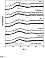
- Figure 3 shows the XRD patterns corresponding to frits obtained in both solar and electric furnace. It can be observed that the XRD profiles of all frits (except the corresponding to WZr frit prepared in electric furnace) only show the characteristic amorphous halo of vitreous materials, in which any diffraction peaks due to crystalline phases are not detected. However, the XRD profile of the frit with the higher melting temperature (WZr) shows small diffraction peaks attributable to ZrO 2 , this indicating that this phase was not completely reacted during the melting process in the electric furnace and it remains as a non-reacted material in the final glass frit.
- WZr melting temperature
- the melting process in a conventional electric furnace originates a high level of corrosion of the crucible wall by the melt, as denoted by the noticeable increasing of alumina content in the final frit composition.
- alumina is detected even in frit composition in which alumina was not added to the raw materials batch.
- the corrosion of crucible is higher as the viscosity of the melt is lower, as expected.
- Table 4 collects the values of Tg for the different glass frits. It can be see that in all cases, glass frits prepared by the use of concentrated solar energy show Tg values lower than those corresponding to frits produced in electric furnace. This result is likely due to differences observed in glass frits compositions. Table 4. Values of Tg (°C) of the glass frits produced in both solar and electric furnace Furnace MF F MTi C WZr Solar 490 574 501 527 554 Electric 552 606 512 553 604
- the short thermal schedule used in solar furnace leads to a lower corrosion of the melt against the walls of the refractory crucibles, thus incorporating low content of alumina to the final glass frit composition.
- boron volatilization is also lower during the melting in the solar furnace.
- the final composition of glass frits prepared in solar furnace shows higher content of fluxing oxides and they will lead to lower viscosity liquids and therefore, to lower Tg values.
- the DTA curves show different exothermic bands indicating that subsequent heat treatments of these glass frits could lead to the devitrification of different crystalline phases.
Landscapes
- Chemical & Material Sciences (AREA)
- Engineering & Computer Science (AREA)
- Materials Engineering (AREA)
- Life Sciences & Earth Sciences (AREA)
- Organic Chemistry (AREA)
- Geochemistry & Mineralogy (AREA)
- General Chemical & Material Sciences (AREA)
- Chemical Kinetics & Catalysis (AREA)
- Sustainable Energy (AREA)
- General Engineering & Computer Science (AREA)
- Mechanical Engineering (AREA)
- Combustion & Propulsion (AREA)
- Thermal Sciences (AREA)
- Physics & Mathematics (AREA)
- Sustainable Development (AREA)
- Glass Compositions (AREA)
Abstract
The present invention relates to a method for preparing glass frits by supplying the total energy required in the process by means of concentrated solar radiation. It is further related with a device for carrying out said method comprising elements such as a solar flat mirror, a solar beam shutter and a solar radiation concentrator. The device further includes means for storing, feeding and containing the raw materials. Several advantages are derived from the use of the method and device of the present invention, which can be summarized in a reduction in energy consumption and an increased productivity of the process.
Description
- The present invention falls under the field of glass frits manufacture.
- It is a first object of the present invention a method for preparing glass frits by supplying the total energy required in the process by means of concentrated solar radiation.
- A further object of the present invention is a device for carrying out said method comprising elements such as a solar flat mirror, a solar beam shutter and a solar radiation concentrator. The device further includes means for storing, feeding and containing the raw materials, such as:
- a raw materials hopper
- a raw materials feeder
- a crucible provided with a tipper arm placed in the focal spot of the concentrated solar radiation
- a water tank for pouring the melted raw materials provided with an articulated support.
- Glass frits are glassy materials prepared by melting a mixture of raw materials at high temperature. Frits are the main component of nearly all ceramic glazes. They are also present in many compositions of different materials where a glassy phase is needed as binder. Currently, on the market there are many varieties of frits, with different physicochemical characteristics: composition, phases, melting point, hardness, colour, erosion resistance, brightness, opacity, shading, etc.
- Nowadays, the production of frits is conducted in continuous melting furnaces and common temperatures in furnaces range between 1350° and 1550°C. Once the raw materials batches are melted, they are cooled in water at high cooling rate; thus, the melt solidifies as small pieces of glass. This melting process implies a significant energy consumption and low efficiency and productivity of the process.
- Frit manufacture is a highly intensive energy process, requiring high temperature usually provided by burning fossil fuels. The highest energy consumption of the process occurs inside the melting oven; in general, the energy necessary for melting accounts for over 75% of the total energy consumed in the frit manufacturing process. The theoretical energy required to convert the raw materials mixture into glass is around 2.7 GJ/t [(Trier, W., Glass Furnaces: Design Construction and Operation; Sheffield: Society of Glass Technology 1987, p. 80.); (Scalet, B.M., et al., 2013. European Commission. Best Available Techniques (BAT) Reference Document for the Manufacture of Glass)].
- This theoretical value takes only into account the chemical heat of reaction and the enthalpy changes associated with heating up the batch from room temperature to the melting temperature. However, from a practical point of view it is required to overcome heat losses linked with upholding the glass melt temperature. The real energy consumption for modern industrial glass melting can vary from 3.5 to 40 GJ/t depending on furnace design and scale [see previous reference by Scalet B.M. et al. (2013)].
- The main drawbacks of the actual procedure are: high cost of furnaces, high energy consumption, low productivity in terms of Kg/h·KJ and high CO2 production. Thus, it is of great importance to search new sustainable processes to reduce energy requirements and moreover to eliminate fossil fuel consumption. Important research work has been carried out aimed to use concentrated solar energy (CSE) in different industrial processes, such as:
- the production of lime from limestone [A. Meier, N. Gremaud, A. Steinfeld. Energy conversion and management 46 (2005) 905],
- alumina from boehmite [I. Padilla, A. López-Delgado, S. López-Andrés, M. Álvarez, R. Galindo, A.J. Vázquez-Vaamonde. The Scientific World Journal (2014); http://dx.doi.org/10.1155/2014/825745] and
- anhydrite from gypsum [A. López-Delgado, S. López-Andrés, I.Padilla, M. Álvarez, R. Galindo, A.J. Vázquez. Geomaterials 4 (2014) 82].
- CSE has also been applied for:
- sintering of alumina [R. Roman, I. Cañadas, J. Rodríguez, M.T. Hernández, M. González. Solar sintering of alumina ceramics: Microstructural development. Solar Energy 82 (2008) 893-902] and
- cordietie-based ceramics [F. Almeida, N. Shohoji, J. Cruz, L. Guerra. Solar sintering of cordierite-based ceramics at low temperatures. Solar Energy 78 (2005) 351-361]
- melting of aluminium from aluminium scrap [Funken, K.-H. et al., 2001. Aluminum remelting using directly solar heated rotary kilns. ASME J. Solar Energy Eng. 123, 117-124],
- production of titanium foams [I. García, E. Gracia-Escosa, M. Bayoda, A. Conde, M.A. Arenas, J. Damborenea, A. Romer, G. Rodríguez. Sustainable production of titanium foams for biomedical applications by Concentrated Solar Energy sintering. Materials Letters 185 (2016) 420-423],
- recovery of zinc from zinc containing materials [Tzouganatos, N. et al. 2013. Thermal recycling of Waelz oxide using concentrated solar energy J. Met. 65, 1733-1743],
- tempering of steels [A. Vázquez, G. P. Rodríguez, J. de Damborenea.Solar EnergyMaterials24 (1991) 751],
- production of titanium nitride [C. Sierra, A. J. Vázquez; Solar Energy Materials and Solar Cells 86 (2005) 86] and
- stainless steel [J. de Damborenea, A.J. Vázquez, B. Fernandez, Materials&Design15 (1994) 41]
- coatings, welding of steels and titanium alloys [A. Romero. I. García, M. A. Arenas, V. López, A. Vázquez. Solar Energy 95 (2013) 131] and
- thermal shock tests on intermetallic materials [D.G. Morris, A. López-Delgado, I. Padilla, M.A. Muñoz-Morris. Solar Energy 112 (2015) 246].
- However, no research has been previously conducted aiming to use CSE for producing glasses or glassy materials such as glass frits or glass enamels. Recently, the feasibility of using concentrated solar radiation to provide a sustainable source of process heat for glass production was investigated [S.Q.S. Ahmad, R.J. Hand, C. Wieckert. Use of concentrated radiation for solar powered glass melting experiments. Solar Energy 109 (2014) 174-182]. Initial experiments involved melting a ternary simple soda-lime-silica (SLS) glass batch, which demonstrated that rapid and full conversion of the crystalline raw materials into an X-ray amorphous vitreous state was possible. The possibility of applying CSE to create a light-beam technology for obtaining art objects with a glass enamel coating has been also explored [V. I. Otmakhov. Firing of glass enamel by concentrated solar radiation. Glass and Ceramics, Vol. 72, Nos. 7-8, 266-268, (2015)]. However it is necessary to point out that the last two mentioned references do not use real CSE to achieve the necessary process energy. Instead, a high flux solar simulator consisting of xenon arc lamps, whose radiation spectrum is close to the solar spectrum, was used as source of heat.
- According to the previous paragraphs there is a need to develop a process wherein real concentrated solar radiation is applied to achieve the energy needed for melting glass frits of different typology.
- Throughout this description the following terms are defined as follows:
- raw materials: any materials that can be used for the manufacture of glass frits such as, but not limited to silica, alkaline/alkalinearth carbonates, alumina, boron oxide, calcium oxide, zirconia, titania, lead oxide, zinc oxide, feldspars and combinations thereof.
- decarbonation: process by which the raw materials used in form of carbonate, i.e. alkaline/alkalinearth carbonates, are decomposed to form the corresponding oxides.
- melting: process by means of which the solid raw materials are transformed into liquid phases.
- homogenization: process by means of which the different liquid phases mix together to get a single liquid melt with physical chemical properties being the same throughout the whole melt.
- A first object of the present invention is a method for manufacturing glass frits comprising decarbonation, melting and homogenization of raw materials wherein the required high density power is provided by concentrated solar energy. In a preferred embodiment, the raw materials are contained in a crucible, being directly heated by means of a concentrated solar beam.
- The raw materials are simultaneously submitted to:
- decarbonation
- melting
- homogenization
- The measured temperature could be higher, up to 1800°C, depending on the concentrated solar beam.
- The melted raw material is subsequently poured over water for cooling, thereby forming the glass frit.
- A further object of the present invention is a device for carrying out the referred method for manufacturing glass frits, said device comprising:
- a solar flat mirror
- a solar beam shutter
- a solar radiation concentrator
- means for storing, feeding and containing the raw materials.
- In a preferred embodiment, the solar radiation concentrator is a parabolic concentrator (1). In a further preferred embodiment:
- the means for storing the raw materials is a hopper (2)
- the means for feeding the raw materials is a feeder (3)
- the means for containing the raw materials is a crucible (4).
- Particularly, the crucible (4) is a refractory crucible.
- The device further comprises a water tank (6) for pouring the melted raw materials.
- Unless otherwise defined, all technical and scientific terms used herein have the same meaning as commonly understood by one of ordinary skilled in the art to which this invention belongs. Methods and materials similar or equivalent to those described herein can be used in the practice of the present invention. Throughout the description and claims the word "comprise" and its variations are not intended to exclude other technical features, elements, or steps. Additional objects, advantages and features of the invention will become apparent to those skilled in the art upon examination of the description or may be learned by practice of the invention. The following examples and drawings are provided by way of illustration and are not intended to be limiting of the present invention.
-
-
Figure 1 : scheme of the solar installation used for carrying out the process of manufacture frits with concentrated solar energy, wherein:- 1. Parabolic concentrator
- 2. Raw materials hopper
- 3. Raw materials feeder
- 4. Crucible
- 5. Crucible tipper arm
- 6. Water tank with articulated support
- 7. Solar beam shutter
- 8. Security sliding floor
- 9. Flat mirror
-
Figure 2 : Temperature-Time registers for the experiment to produce glass frits in solar furnace (thermocouple placed outside in the crucible bottom) and in electric furnace. -
Figure 3 : XRD patterns of the glass frits obtained in solar furnace (gray) and electric furnace (black). -
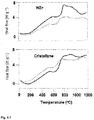
Figures 4.1 and 4.2 : Thermal behaviour of the glass frits obtained in solar furnace (gray) and electric furnace (black). - The invention relates to a new process to obtain glass frits using concentrated solar energy, thereby involving several remarkable advantages in comparison with traditional processes. These traditional processes carry out the heating of raw materials in a reactor consisting of a crucible where those materials are heated, decarbonated, melted and homogenized to produce the final product (glass frit). Most of furnaces used in the commercial manufacture are both electric and fuel heated furnaces. In both cases there is a huge energy consumption and also a large production of CO2.
- In the conventional process to produce frits, raw materials are placed inside a crucible, which is heated from outside to inside. In the present invention (see
Fig. 1 ), using a vertical axis solar radiation parabolic concentrator (1), the heating is focalised directly on the raw materials batch, inside the crucible (4). Accordingly, a huge saving in energy consumption would be obtained because of the higher concentrated solar power density. Additionally, the process duration is drastically reduced because the raw materials are under the solar radiation focal spot, as soon as the crucible (4) is in vertical position and the shutter (7) is opened. Thus, they begin to be immediately heated by the concentrated solar beam coming from the parabolic concentrator (1). As the power density of this concentrated solar beam is much higher than in traditional furnaces, the heating rate is very high, and accordingly the time to achieve the desired reaction temperature is additionally reduced. - This invention proposes a new process for frits manufacture using a specific system of thermal solar energy consisting of a concentrating solar installation of vertical axis custom-built to the characteristics of the process. With this design it is possible to use a very high power density to heat directly and faster the raw materials up to high temperatures. The process comprises the direct heating of raw materials with concentrated solar energy for increasing the efficiency in time and energy consumption.
- Basically the new frit production process is as follows:
- 1.- Raw material batch is introduced in the reactor, i. e., a crucible (4) located in the focal spot of the parabolic solar concentrator (1), by means of a raw materials feeder (3), which one finished the load is displaced to a position outside the parabolic concentrator.
- 2.- The solar beam shutter (7) is opened to allow solar beam to be redirected from the flat mirror (9) to the parabolic concentrator (1).
- 3.- The high solar power density existing in the focal spot produces a fast heating, which leads to the simultaneous decarbonation and melting of raw materials and homogenization of the final melt.
- 3.- Once the melt reaches the required temperature, it is fast cooled by pouring on a water tank (6) to produce a frit. The pouring is carried out by means of the crucible tipper arm (5) which rotates the crucible (4) to permit that the melt pours.
- Once the crucible (4) is again in vertical position, it is fulfilled with new raw material mixture and the process follows by step "1 ", while the water tank (6) is displaced by an articulate support to a position outside the parabolic concentrator.
- With this new process, time required for raw material heating, decarbonation melting and homogenization is extremely short. Consequently, the transformation rate of raw materials in the final glass is much higher than in traditional processes. As it is shown in the preferred embodiments, none of the original raw materials are detected in the final frit. Notwithstanding the shorter process duration, the quality of the final product is similar to that of the same frits melted by a conventional process.
- The process for preparing glass frits according to the present invention has several advantages compared to those using conventional furnaces:
- 1.- Because of the use of solar energy there is not any direct or indirect CO2 emission due to energy generation. This is a clear benefit from the point of view of green house effect. This benefit is very important since glass frit industry is a high consumer of fossil fuel because a high process temperature is required. Even if furnaces are electrically heated there is a hidden fossil fuel consumption because about 35 % of electricity is produced with fossil fuels and the production yield of those plants is about 40 %. Additionally, the losses associated to energy transformation and transport must be considered.
- 2.- The second benefit is that the only cost of this new process is the installation and its maintenance.
- 3.- Raw materials particles have an irregular surface acting as a perfect sink of solar radiation and increasing the global heat transference because there is not any reflection. Even if the concentrated solar beams heat a solid surface, e. g., the inside crucible wall as happens with the radiation of flames in gas furnaces or the heating resistance in electric furnaces, the heat losses would be slightly smaller. Thereby, a reduction in total energy involved in the process is achieved and there is a better global heat transference throughout the surface of raw materials. Traditional processes require higher temperature at the outside crucible wall. The conduction coefficient of the crucible material controls the heating time because conduction coefficient is always the controlling step. However, a higher temperature at the external wall of the crucible is needed for heating the raw material batch inside the crucible. It is well known that an increment in temperature means a cost increment in any process.
- 4.- When raw materials grains in the top of the crucible are melted, the liquid phase originated goes down along the pores heating the grains located in lower layers. This melted liquid is going down vertically heating all the grains it finds. Consequently, the non-reacted raw materials are faster heated due to the larger surface contact between the melted material and the grains surface. The global energy transference is much higher than if the heating were done throughout the walls of crucible as in traditional process, where this effect takes place only near the wall.
- Additionally the higher power density of the concentrated solar beam increases the global heat transference to the raw materials batch, with a reduction in heating time and the subsequent increment in productivity.
- 5.- Because the raw material batch is directly heated, the outside temperature of the crucible is lower than in traditional processes, it means lower heat losses and in consequence a reduction in energy consumption of the process.
- 6.- Concerning the crucible cost, traditional processes use materials with high thermal resistance and simultaneously with a high conduction coefficient. Both characteristics means higher price. In the present invention, raw material batch is directly heated and the crucible can be made with lower cost insulating refractory material. Moreover there is a very important reduction in the mechanical erosion and chemical corrosion of the crucible inner wall increasing its operation life.
- 7.- The final consequence of those previous advantages is that this new process leads to a reduction higher than 80% in the reaction time (heating, decarbonation and melting) than means an increment in productivity of the process.
- The chemical composition of commercial glass frits includes the combination of several components:
- Glass formers: SiO2, B2O3
- Fluxing oxides: Na2O, K2O, PbO, B2O3, Li2O
- Stabilizers: CaO, BaO, MgO, PbO, Al2O3, ZnO
- Opacifyers: ZrO2, SnO2, TiO2
- Devitrifying oxides: ZnO, CaO, BaO, MgO, TiO2
- According to different physical and chemical characteristics, commercial frits are classified in the following six groups:
- 1- Crystalline frits
- 2- White of zirconium frits
- 3- Bright, transparent, middle fusibility frits
- 4- Fluxing frits
- 5- Reactive fluxing frits
- 6- Matte frits
- The chemical composition of the different groups is indicated in Table 1.
Table 1. Chemical composition interval (wt. %) of commercial glass frits. Oxide Crystalline White of zirconium Middle fusibility Fluxing Reactive fluxing Matte Alkaline 3-6 3-7 3-7 0-15 --- 0-10 CaO 4-8 4-8 3-6 0-10 --- 0-20 BaO 0-2 0-2 0-2 --- --- --- ZnO 4-8 4-8 3-6 0-5 --- 0-30 PbO 0-20 0-10 30-40 0-85 45-69 0-35 Al2O3 4-8 4-8 2-4 --- --- 0-5 B2O3 5-15 10-15 5-10 0-30 20 2-40 SiO2 50-60 50-55 40-50 15-50 11-35 30-60 ZrO2 --- 7-12 --- --- --- 0-5 TiO2 --- --- --- --- --- 0-10 - For the embodiments of the present invention, glass compositions belonging to five different frits groups (Table 1) were formulated, namely, crystalline (C); white of zirconium (WZr); middle fusibility (MF); fluxing (F) and matte of titanium (MTi). The compositions of the starting frits are shown in Table 2.
Table 2. Starting chemical composition (wt. %) of the investigated glasses. Oxide C WZr MF F MTi SiO 2 50 50 40 50 40 B2O3 15 15 10 20 20 Al2O3 4 4 2 --- 2 Na2O 3 --- 4 10 2 K2O --- --- --- 10 --- Li2O 3 7 3 --- 2 CaO 8 4 6 10 2 BaO 2 2 2 --- 25 ZnO 5 8 3 --- 7 PbO 10 --- 30 --- --- ZrO2 --- 10 --- --- --- Theoretical Tmelting (°C) 993 1079 822 880 885 - The raw materials used for obtaining the glass frit were low iron content silica sand, reagent grade Al2O3, B2O3, ZnO, PbO and ZrO2. Alkali and alkaline earth elements were introduced as reagent grade carbonates. The mixtures were homogenised in a planetary ball mill (TURBULA) for 15 min. For comparison of the properties of final frits batches were melted in parallel in a vertical axis parabolic solar furnace and in a traditional electric furnace. In both cases, batches were melted in tabular alumina crucibles. Once melted at specific temperature, the melted liquid was poured on cool water.
- For carrying out the preparation of frits using concentrated solar energy, a vertical axis parabolic solar furnace was used.
- A scheme of the solar installation used for the manufacture frits with concentrated solar energy is shown in
Fig. 1 , wherein the concentrated solar energy is provided by means of a flat mirror (9), a solar beam shutter (7) and a parabolic concentrator (1). - The raw material is stored into a raw material hopper (2) and is loaded to the crucible (4), placed in the focal spot of the concentrated solar beam, by means of a raw materials feeder (3). Once the load is finished, the raw material feeder (3) is displaced to a position in which it is not damaged by the concentrated solar beam. Additionally, no shadows should are originated by the position of this feeder (3).
- Once the reaction and melting is concluded and in order to carry out the fast cooling of the final melt, an articulated support displaces a water tank (6) to the adequate position in which the final melt is poured.
- The pouring of the final melt over water for cooling, is performed by using a crucible tipper arm (5) that supports the crucible (4).
- This facility was located in the Medium Size Solar Furnaces (MSSFs) of CNRS-PROMESS Solar facilities (Font Romeu-Odeillo, France).This solar furnace is a 0.9 kW installation equipped with a parabolic reflector of 1.5 m diameter that produces a focal spot, ca. 15 mm in diameter, with a very high power density ca. 1000 W/m2. Incident solar radiation has a shutter positioned between the parabolic concentrator and the flat mirror (heliostat). The heliostat follows the sun track and it reflects the sun radiation vertically to the parabolic concentrator. To measure the temperature under the crucible bottom a type K thermocouple was set.
- Once the raw materials were melted inside the crucible, the melt was maintained few minutes under solar radiation exposure to get homogenization and then it was poured on water to produce the glass frit.
- For comparison of the properties of final frits and the efficiency of the process, the same glass frit compositions were melted in an electric furnace. In both cases, the same type and dimensions of the crucible and batch weight were employed.
-
Figure 2 shows the thermal schedule followed for obtaining the frits in both solar and electric furnaces. As it can be seen, the use of concentrated solar energy produces a reduction of the time process higher than 80% in comparison to the conventional electric furnace. - The results of the characterization of different frits prepared by using both concentrated solar and electric furnace are shown. The aim of this characterization is to determine if the type of energy, density power and thermal schedule used in the preparation of frits leads to materials with the same physical-chemical characteristics.
- The chemical analysis of the resulting glass frits was determined by X-ray fluorescence (XRF) using a Bruker S8 Tiger spectrometer on pressed pellets of powder glass samples (<63 µm). The determination of B and Li was performed by optical emission inductively coupled plasma spectrometry (ICP-OES) in a Varian 725-ES spectrometer. The evaluation of the amorphous nature of the frits after melting was performed by X-ray diffraction (XRD) using Bruker D8 Advance equipment with Ni-filtered Cu Kα radiation operating at 30 mA and 40 kV. Data were recorded in the 5-60° 2θ range (step size 0.019732° and 0.5 s counting time for each step).
- The thermal stability of the glass frits was analysed by differential thermal analysis (DTA) on powder (<63 µm) frit samples. DTA runs were performed from room temperature to 1200 °C, at a heating rate of 50°C·min-1 under flowing air (100) in TA Instrument (mod SDT-Q600).
-
Figure 3 shows the XRD patterns corresponding to frits obtained in both solar and electric furnace. It can be observed that the XRD profiles of all frits (except the corresponding to WZr frit prepared in electric furnace) only show the characteristic amorphous halo of vitreous materials, in which any diffraction peaks due to crystalline phases are not detected. However, the XRD profile of the frit with the higher melting temperature (WZr) shows small diffraction peaks attributable to ZrO2, this indicating that this phase was not completely reacted during the melting process in the electric furnace and it remains as a non-reacted material in the final glass frit. - This is an additional advantage because this new process will allow melting frit compositions with high content of refractory oxide, which are hardly melted in conventional furnaces.
- On the other hand, for each different type of frits, it can be seen that the XRD profiles are very similar. It is worthy that in spite of the shorter time used in the new solar melting process, the structure of the glass network of resulting frits is very similar.
- The chemical composition of the final frits prepared in both solar and electric furnace and determined by XRF and ICP-OES are show in Table 3. The theoretical initial composition of the raw materials mixtures is also included.
Table 3. Chemical composition (% wt) of the frits prepared in both solar and electric furnace. Oxide (% wt) Theoretical composition Electric furnace Solar furnace Fluxing Frit SiO 2 50 47.04 53.72 B2O3 20 11.80 13.4 Al2O3 0 15.00 2.24 Na2O 10 9.07 11.1 K2O 10 6.67 8.74 CaO 10 9.35 10.03 White of Zirconium Frit SiO 2 50 43.47 50.52 B2O3 15 8.74 10.6 Al2O3 4 22.5 5.71 Li2O 7 3.67 5.13 CaO 4 3.34 4.39 BaO 2 1.54 2.29 ZnO 8 6.40 8.10 ZrO2 10 8.27 11.25 Crystalline Frit SiO 2 50 50.30 52.60 B2O3 15 9.75 11.80 Al2O3 4 11.50 5.83 Na2O 3 3.60 3.97 Li2O 3 1.83 2.59 CaO 8 4.33 4.43 BaO 2 1.91 2.33 ZnO 5 5.27 5.38 PbO 10 10.49 10.05 Middle Fusibility Frit SiO 2 40 37.88 40.19 B2O3 10 5.84 7.12 Al2O3 2 11.0 3.98 Na2O 4 4.10 4.70 Li2O 3 1.71 2.24 CaO 6 5.80 6.23 BaO 2 1.71 2.24 ZnO 3 3.00 3.16 PbO 30 28.18 29.52 Matte of Titanium Frit SiO 2 40 41.09 41.81 B2O3 20 14.60 15.1 Al2O3 2 7.76 4.02 Na2O 2 2.13 2.65 Li2O 2 1.28 1.63 ZnO 2 1.69 1.69 PbO 25 24.35 25.59 TiO 27 6.44 6.86 - It can be seen that the melting process in a conventional electric furnace originates a high level of corrosion of the crucible wall by the melt, as denoted by the noticeable increasing of alumina content in the final frit composition. Thus, alumina is detected even in frit composition in which alumina was not added to the raw materials batch. In general the corrosion of crucible is higher as the viscosity of the melt is lower, as expected.
- It is also observed B2O3 losses by volatilization of boron that are much higher when the melting process is performed in the electric furnace than in the glass frits obtained by concentrated solar energy. This result can be attributable to the longer time required for melting in electric furnace. As above mentioned, the use of high power density, as provided by a solar concentrator, to carry out the manufacture of frits allows reducing the process time in about 80% in contrast with the long time required to obtain the same material in a conventional electric furnace. The variation of the rest of components in the composition of frits corresponds to the adjustment of the mass balance.
- Accordingly, it can be concluded that the use of concentrated solar energy to manufacture glass frits presents extra advantages as: lower corrosion of crucible wall and lower volatilization of boron in the melting process.
- The thermal behaviour of the glass frits was evaluated by DTA.
Figures 4.1 and 4.2 show the DTA curves of the glass frits produced in both solar and electric furnace. In general, the curves corresponding to each frit type shows a similar profile, which again denotes that in spite of the shorter time required for completing the melting process in the solar furnace, the structure of the final frits must be analogous to that of frits processed in a electric furnace. All the thermograms show the distinctive endothermic fall in the baseline corresponding to the glass transition temperature (Tg). - Table 4 collects the values of Tg for the different glass frits. It can be see that in all cases, glass frits prepared by the use of concentrated solar energy show Tg values lower than those corresponding to frits produced in electric furnace. This result is likely due to differences observed in glass frits compositions.
Table 4. Values of Tg (°C) of the glass frits produced in both solar and electric furnace Furnace MF F MTi C WZr Solar 490 574 501 527 554 Electric 552 606 512 553 604 - As above mentioned, the short thermal schedule used in solar furnace leads to a lower corrosion of the melt against the walls of the refractory crucibles, thus incorporating low content of alumina to the final glass frit composition. Moreover, boron volatilization is also lower during the melting in the solar furnace. As results, the final composition of glass frits prepared in solar furnace shows higher content of fluxing oxides and they will lead to lower viscosity liquids and therefore, to lower Tg values. At higher temperatures, the DTA curves show different exothermic bands indicating that subsequent heat treatments of these glass frits could lead to the devitrification of different crystalline phases.
Claims (9)
- Method for manufacturing glass frits comprising decarbonation, melting and homogenization of raw materials wherein the required high density power is provided by concentrated solar energy.
- Method for manufacturing glass frits according to claim 1, wherein the raw materials are contained in a crucible (4), said raw materials being directly heated by means of a concentrated solar beam.
- Method for manufacturing glass frits according to either claims 1 or 2, wherein the raw materials are simultaneously submitted to:- decarbonation- melting- homogenizationduring a period ranging from 15 to 45 min at a temperature measured under the crucible bottom higher than 1400°C.
- Method for manufacturing glass frits according to any of the preceding claims, wherein the melted raw material is subsequently poured over water for cooling, thereby forming the glass frit.
- Device for carrying out a method for manufacturing glass frits as defined in claims 1 to 5, said device comprising:- a solar flat mirror (9)- a solar beam shutter (7)- a solar radiation concentrator (1)- means for storing, feeding and containing the raw materials.
- Device according to claim 5, wherein the solar radiation concentrator is a parabolic concentrator (1).
- Device according to either claims 5 or 6, wherein:- the means for storing the raw materials is a hopper (2)- the means for feeding the raw materials is a feeder (3)- the means for containing the raw materials is a crucible (4).
- Device according to claim 7, wherein the crucible (4) is a refractory crucible.
- Device according to any of claims 5 to 8, wherein it further comprises a water tank (6) for pouring the melted raw materials.
Priority Applications (3)
| Application Number | Priority Date | Filing Date | Title |
|---|---|---|---|
| EP17382111.7A EP3372561A1 (en) | 2017-03-06 | 2017-03-06 | Method and device for manufacturing glass frits |
| PCT/EP2018/055296 WO2018162383A1 (en) | 2017-03-06 | 2018-03-05 | Method and device for manufacturing glass frits |
| ES201990069A ES2732490B2 (en) | 2017-03-06 | 2018-03-05 | METHOD AND DEVICE FOR THE MANUFACTURE OF GLASS FRIES |
Applications Claiming Priority (1)
| Application Number | Priority Date | Filing Date | Title |
|---|---|---|---|
| EP17382111.7A EP3372561A1 (en) | 2017-03-06 | 2017-03-06 | Method and device for manufacturing glass frits |
Publications (1)
| Publication Number | Publication Date |
|---|---|
| EP3372561A1 true EP3372561A1 (en) | 2018-09-12 |
Family
ID=58277240
Family Applications (1)
| Application Number | Title | Priority Date | Filing Date |
|---|---|---|---|
| EP17382111.7A Withdrawn EP3372561A1 (en) | 2017-03-06 | 2017-03-06 | Method and device for manufacturing glass frits |
Country Status (3)
| Country | Link |
|---|---|
| EP (1) | EP3372561A1 (en) |
| ES (1) | ES2732490B2 (en) |
| WO (1) | WO2018162383A1 (en) |
Citations (2)
| Publication number | Priority date | Publication date | Assignee | Title |
|---|---|---|---|---|
| CN2808897Y (en) * | 2005-06-30 | 2006-08-23 | 广州赛唯热工设备有限公司 | Glass kiln solar preheating and residual heat recovery device |
| FR3004522A1 (en) * | 2013-04-16 | 2014-10-17 | China Building Material Inst Of Solar Energy Applic Ltd Co | HEATING DEVICE HAVING HIGH TEMPERATURE |
Family Cites Families (1)
| Publication number | Priority date | Publication date | Assignee | Title |
|---|---|---|---|---|
| US9441426B2 (en) * | 2013-05-24 | 2016-09-13 | Oil States Industries, Inc. | Elastomeric sleeve-enabled telescopic joint for a marine drilling riser |
-
2017
- 2017-03-06 EP EP17382111.7A patent/EP3372561A1/en not_active Withdrawn
-
2018
- 2018-03-05 ES ES201990069A patent/ES2732490B2/en not_active Expired - Fee Related
- 2018-03-05 WO PCT/EP2018/055296 patent/WO2018162383A1/en not_active Ceased
Patent Citations (2)
| Publication number | Priority date | Publication date | Assignee | Title |
|---|---|---|---|---|
| CN2808897Y (en) * | 2005-06-30 | 2006-08-23 | 广州赛唯热工设备有限公司 | Glass kiln solar preheating and residual heat recovery device |
| FR3004522A1 (en) * | 2013-04-16 | 2014-10-17 | China Building Material Inst Of Solar Energy Applic Ltd Co | HEATING DEVICE HAVING HIGH TEMPERATURE |
Non-Patent Citations (24)
| Title |
|---|
| A. LOPEZ-DELGADO; S. LÓPEZ-ANDRÉS; I.PADILLA; M. ALVAREZ; R. GALINDO; A.J. VAZQUEZ., GEOMATERIALS, vol. 4, 2014, pages 82 |
| A. MEIER; N. GREMAUD; A. STEINFELD, ENERGY CONVERSION AND MANAGEMENT, vol. 46, 2005, pages 905 |
| A. ROMERO; I. GARCIA; M. A. ARENAS; V. LOPEZ; A. VAZQUEZ, SOLAR ENERGY, vol. 95, 2013, pages 131 |
| A. VAZQUEZ; G. P. RODRIGUEZ; J. DE DAMBORENEA, SOLAR ENERGYMATERIALS, vol. 24, 1991, pages 751 |
| AEO JX: "Markus Kayser - Solar Sinter Project", 27 June 2011 (2011-06-27), XP002773417, Retrieved from the Internet <URL:http://youtu.be/ptUj8JRAYu8> [retrieved on 20170904] * |
| ANONYMOUS: "Solar Furnace", 5 December 2016 (2016-12-05), XP055403777, Retrieved from the Internet <URL:https://en.wikipedia.org/w/index.php?title=Solar_furnace&oldid=753232002> [retrieved on 20170905] * |
| C. SIERRA; A. J. VAZQUEZ, SOLAR ENERGY MATERIALS AND SOLAR CELLS, vol. 86, 2005, pages 86 |
| D.G. MORRIS; A. LOPEZ-DELGADO; I. PADILLA; M.A. MUNOZ-MORRIS, SOLAR ENERGY, vol. 112, 2015, pages 246 |
| F. ALMEIDA; N. SHOHOJI; J. CRUZ; L. GUERRA: "Solar sintering of cordierite-based ceramics at low temperatures", SOLAR ENERGY, vol. 78, 2005, pages 351 - 361 |
| FUNKEN, K.-H. ET AL.: "Aluminum remelting using directly solar heated rotary kilns", ASME J. SOLAR ENERGY ENG., vol. 123, 2001, pages 117 - 124 |
| GREENPOWERSCIENCE: "Fresnel lens sun collector melting glass solar powered foundry", 18 July 2007 (2007-07-18), XP002773416, Retrieved from the Internet <URL:http://youtu.be/_lG1GfKVoYE> [retrieved on 20170904] * |
| I. GARCIA; E. GRACIA-ESCOSA; M. BAYODA, A. CONDE; M.A. ARENAS; J. DAMBORENEA; A. ROMER; G. RODRIGUEZ.: "Sustainable production of titanium foams for biomedical applications by Concentrated Solar Energy sintering", MATERIALS LETTERS, vol. 185, 2016, pages 420 - 423, XP029810639, DOI: doi:10.1016/j.matlet.2016.09.037 |
| I. PADILLA; A. LOPEZ-DELGADO; S. LÓPEZ-ANDRÉS; M. ALVAREZ; R. GALINDO; A.J. VAZQUEZ-VAAMONDE, THE SCIENTIFIC WORLD JOURNAL, 2014, Retrieved from the Internet <URL:http://dx.doi.org/10.1155/2014/825745> |
| J. DE DAMBORENEA; A.J. VAZQUEZ; B. FERNANDEZ, MATERIALS&DESIGN, vol. 15, 1994, pages 41 |
| MICHAEL ELLESTAD: "DIY Fresnel lens solar glass melting foundry", 17 January 2015 (2015-01-17), XP002773415, Retrieved from the Internet <URL:http://youtu.be/xyCH2T5PWUc> [retrieved on 20170904] * |
| R. ROMAN; I. CANADAS; J. RODRIGUEZ; M.T. HERNANDEZ; M. GONZALEZ: "Solar sintering of alumina ceramics: Microstructural development", SOLAR ENERGY, vol. 82, 2008, pages 893 - 902, XP023905031, DOI: doi:10.1016/j.solener.2008.04.002 |
| S.Q.S. AHMAD ET AL: "Use of concentrated radiation for solar powered glass melting experiments", SOLAR ENERGY, vol. 109, November 2014 (2014-11-01), GB, pages 174 - 182, XP055403539, ISSN: 0038-092X, DOI: 10.1016/j.solener.2014.08.007 * |
| S.Q.S. AHMAD; R.J. HAND; C. WIECKERT: "Use of concentrated radiation for solar powered glass melting experiments", SOLAR ENERGY, vol. 109, 2014, pages 174 - 182, XP055403539, DOI: doi:10.1016/j.solener.2014.08.007 |
| SCALET, B.M. ET AL., EUROPEAN COMMISSION. BEST AVAILABLE TECHNIQUES (BAT) REFERENCE DOCUMENT FOR THE MANUFACTURE OF GLASS, 2013 |
| SHEFFIELD, SOCIETY OF GLASS TECHNOLOGY, 1987, pages 80 |
| TRIER, W., GLASS FURNACES: DESIGN CONSTRUCTION AND OPERATION |
| TZOUGANATOS, N. ET AL.: "Thermal recycling of Waelz oxide using concentrated solar energy", J. MET., vol. 65, 2013, pages 1733 - 1743, XP035350822, DOI: doi:10.1007/s11837-013-0778-x |
| V. I. OTMAKHOV: "Firing of glass enamel by concentrated solar radiation", GLASS AND CERAMICS, vol. 72, no. 7 - 8, 2015, pages 266 - 268, XP035909514, DOI: doi:10.1007/s10717-015-9770-y |
| V. I. OTMAKHOV: "Firing of glass enamel by concentrated solar radiation", GLASS AND CERAMICS, vol. 72, no. 7-8, 2015, pages 266 - 268, XP035909514, DOI: 10.1007/s10717-015-9770-y * |
Also Published As
| Publication number | Publication date |
|---|---|
| WO2018162383A1 (en) | 2018-09-13 |
| ES2732490R1 (en) | 2019-12-17 |
| ES2732490A2 (en) | 2019-11-22 |
| ES2732490B2 (en) | 2020-05-07 |
Similar Documents
| Publication | Publication Date | Title |
|---|---|---|
| Sun et al. | Effect of Al2O3 content on BaO–Al2O3–B2O3–SiO2 glass sealant for solid oxide fuel cell | |
| CN101838106B (en) | Borosilicate glass tube for photo-thermal power generation | |
| CN106116144B (en) | A kind of preparation method of red high-boron-silicon glass | |
| CN101428966A (en) | Borosilicate glass suitable for electric light source | |
| CN103833223B (en) | Space flight flexible foundation glass ingredient | |
| CN104176931B (en) | Solar energy high temperature thermal-collecting tube special neutral borosilicate glass tube and preparation method thereof | |
| Ayawanna et al. | Effect of bismuth oxide on crystallization and sealing behavior of barium borosilicate glass sealant for SOFCs | |
| EP4412965A1 (en) | Vacuum insulated panel with tellurium oxide and/or vanadium oxide inclusive seal | |
| Romero et al. | Eco-efficient melting of glass frits by concentrated solar energy | |
| CN101374776A (en) | Method for producing glass composition for lamp, and lamp | |
| Zhang et al. | Tuning the interfacial reaction between bismuth‐containing sealing glasses and Cr‐containing interconnect: effect of ZnO | |
| Yang et al. | Research progress on high-level waste vitrification based on Joule heating ceramic melter | |
| CN101891383B (en) | Glass for photo-thermal generation heat-collecting pipe | |
| Ahmad et al. | Use of concentrated radiation for solar powered glass melting experiments | |
| CN110194591B (en) | Germanate infrared transmitting glass and preparation method thereof | |
| WO2018162383A1 (en) | Method and device for manufacturing glass frits | |
| US20210139366A1 (en) | Sealing compositions | |
| Romero et al. | Method and device for manufacturing glass frits | |
| Flügel et al. | Development of an Improved Devitrifiable Fuel Cell Sealing Glass: I. Bulk Properties | |
| CN100443799C (en) | Micro-crystal glass lampshade and preparation method thereof | |
| Hao et al. | Theoretical calculations of the thermal expansion coefficient of glass-ceramic sealing materials in solid oxide electrolysis cell | |
| CN102390927B (en) | Glass suitable for trough photo-thermal power generation heat collection tube | |
| WO2024112499A1 (en) | Vacuum insulated panel with tellurium oxide and/or boron and bismuth oxide inclusive seal | |
| EP4423024A1 (en) | Vacuum insulated panel seal | |
| US10584065B2 (en) | Refractory block and glass-melting furnace |
Legal Events
| Date | Code | Title | Description |
|---|---|---|---|
| PUAI | Public reference made under article 153(3) epc to a published international application that has entered the european phase |
Free format text: ORIGINAL CODE: 0009012 |
|
| STAA | Information on the status of an ep patent application or granted ep patent |
Free format text: STATUS: THE APPLICATION HAS BEEN PUBLISHED |
|
| AK | Designated contracting states |
Kind code of ref document: A1 Designated state(s): AL AT BE BG CH CY CZ DE DK EE ES FI FR GB GR HR HU IE IS IT LI LT LU LV MC MK MT NL NO PL PT RO RS SE SI SK SM TR |
|
| AX | Request for extension of the european patent |
Extension state: BA ME |
|
| STAA | Information on the status of an ep patent application or granted ep patent |
Free format text: STATUS: THE APPLICATION IS DEEMED TO BE WITHDRAWN |
|
| 18D | Application deemed to be withdrawn |
Effective date: 20190313 |