EP3372526A1 - Container cover that facilitates creating negative pressure and long time sealing - Google Patents
Container cover that facilitates creating negative pressure and long time sealing Download PDFInfo
- Publication number
- EP3372526A1 EP3372526A1 EP18250006.6A EP18250006A EP3372526A1 EP 3372526 A1 EP3372526 A1 EP 3372526A1 EP 18250006 A EP18250006 A EP 18250006A EP 3372526 A1 EP3372526 A1 EP 3372526A1
- Authority
- EP
- European Patent Office
- Prior art keywords
- valve rod
- container
- relief valve
- cover member
- guide block
- Prior art date
- Legal status (The legal status is an assumption and is not a legal conclusion. Google has not performed a legal analysis and makes no representation as to the accuracy of the status listed.)
- Granted
Links
Images






Classifications
-
- B—PERFORMING OPERATIONS; TRANSPORTING
- B65—CONVEYING; PACKING; STORING; HANDLING THIN OR FILAMENTARY MATERIAL
- B65D—CONTAINERS FOR STORAGE OR TRANSPORT OF ARTICLES OR MATERIALS, e.g. BAGS, BARRELS, BOTTLES, BOXES, CANS, CARTONS, CRATES, DRUMS, JARS, TANKS, HOPPERS, FORWARDING CONTAINERS; ACCESSORIES, CLOSURES, OR FITTINGS THEREFOR; PACKAGING ELEMENTS; PACKAGES
- B65D81/00—Containers, packaging elements, or packages, for contents presenting particular transport or storage problems, or adapted to be used for non-packaging purposes after removal of contents
- B65D81/18—Containers, packaging elements, or packages, for contents presenting particular transport or storage problems, or adapted to be used for non-packaging purposes after removal of contents providing specific environment for contents, e.g. temperature above or below ambient
- B65D81/20—Containers, packaging elements, or packages, for contents presenting particular transport or storage problems, or adapted to be used for non-packaging purposes after removal of contents providing specific environment for contents, e.g. temperature above or below ambient under vacuum or superatmospheric pressure, or in a special atmosphere, e.g. of inert gas
- B65D81/2007—Containers, packaging elements, or packages, for contents presenting particular transport or storage problems, or adapted to be used for non-packaging purposes after removal of contents providing specific environment for contents, e.g. temperature above or below ambient under vacuum or superatmospheric pressure, or in a special atmosphere, e.g. of inert gas under vacuum
- B65D81/2038—Containers, packaging elements, or packages, for contents presenting particular transport or storage problems, or adapted to be used for non-packaging purposes after removal of contents providing specific environment for contents, e.g. temperature above or below ambient under vacuum or superatmospheric pressure, or in a special atmosphere, e.g. of inert gas under vacuum with means for establishing or improving vacuum
-
- A—HUMAN NECESSITIES
- A47—FURNITURE; DOMESTIC ARTICLES OR APPLIANCES; COFFEE MILLS; SPICE MILLS; SUCTION CLEANERS IN GENERAL
- A47J—KITCHEN EQUIPMENT; COFFEE MILLS; SPICE MILLS; APPARATUS FOR MAKING BEVERAGES
- A47J47/00—Kitchen containers, stands or the like, not provided for in other groups of this subclass; Cutting-boards, e.g. for bread
- A47J47/02—Closed containers for foodstuffs
- A47J47/08—Closed containers for foodstuffs for non-granulated foodstuffs
- A47J47/10—Closed containers for foodstuffs for non-granulated foodstuffs with arrangements for keeping fresh
-
- B—PERFORMING OPERATIONS; TRANSPORTING
- B65—CONVEYING; PACKING; STORING; HANDLING THIN OR FILAMENTARY MATERIAL
- B65D—CONTAINERS FOR STORAGE OR TRANSPORT OF ARTICLES OR MATERIALS, e.g. BAGS, BARRELS, BOTTLES, BOXES, CANS, CARTONS, CRATES, DRUMS, JARS, TANKS, HOPPERS, FORWARDING CONTAINERS; ACCESSORIES, CLOSURES, OR FITTINGS THEREFOR; PACKAGING ELEMENTS; PACKAGES
- B65D43/00—Lids or covers for rigid or semi-rigid containers
- B65D43/02—Removable lids or covers
-
- B—PERFORMING OPERATIONS; TRANSPORTING
- B65—CONVEYING; PACKING; STORING; HANDLING THIN OR FILAMENTARY MATERIAL
- B65B—MACHINES, APPARATUS OR DEVICES FOR, OR METHODS OF, PACKAGING ARTICLES OR MATERIALS; UNPACKING
- B65B31/00—Packaging articles or materials under special atmospheric or gaseous conditions; Adding propellants to aerosol containers
- B65B31/04—Evacuating, pressurising or gasifying filled containers or wrappers by means of nozzles through which air or other gas, e.g. an inert gas, is withdrawn or supplied
Definitions
- the present invention relates to negative pressure storage container technology and more particularly, to a container cover that enables a pumping piston to pump air out of a container on which the container cover is covered after the user rotates a rotary device.
- US Patent Number 9,296,542 discloses a vacuum storage container, which includes a container housing, a drawer mounted in the container housing and movable between a closed position and an open position, a rotary knob pivotally mounted in a door cover of the drawer, clockwork coupled to the rotary knob, a drive gear affixed to the rotary knob, a transmission gear set rotatable by the drive gear, an eccentric wheel rotatable by the transmission gear set, a pumping pump mounted in the drawer and coupled to the eccentric wheel for creating a vacuum in the container housing, an ejection mechanism adapted for ejecting the drawer out of the container housing, and an operating member control mechanism adapted for locking the drawer to the container housing and operable to unlock the drawer for enabling the drawer to be ejected out of the container housing by the ejection mechanism. Since the transmission gear set is arranged in a transverse direction, if you want to use the container cover in a cylindrical can, a barrel or a bottle-like container, the container cover
- the present invention has been accomplished under the circumstances in view. It is therefore the main object of the present invention to provide a container cover consisting of a rotary device, an outer cover member, an inner cover member, a first guide block, second guide block, a pumping piston and a piston seat, and adapted for covering a storage container.
- the component parts are so arranged that when the rotary device is driven by a user to rotate the first guide block, guide rods of the first guide block are moved along a first continuous wave-shaped track of the second guide block, causing the second guide block and the pumping piston to move alternatively up and to further pump air out of the storage container through an air-pimping hole of the piston seat to create a negative pressure.
- the container cover of the invention has the characteristics of simple structure, space saving a wide application range.
- the container cover can be configured for covering a vacuum storage can, vacuum storage box, vacuum storage bottle, decanter, or any of a variety of storage containers of different shapes and sizes, facilitating creation of a negative pressure in the storage container.
- a vacuum storage can vacuum storage box, vacuum storage bottle, decanter, or any of a variety of storage containers of different shapes and sizes, facilitating creation of a negative pressure in the storage container.
- the storage food ingredients and eatable items in the storage container can be maintained fresh, avoiding ruptured storage items due to moisture or oxidation.
- the container cover further comprises a relief valve rod.
- the relief valve rod has the top end thereof capped with a flexible end cap.
- the flexible end cap will curve down, giving a visual indication of the presence of the negative pressure in the storage container.
- the container cover of this first embodiment comprises a rotary device 1, an outer cover member 2, an inner cover member 3, a first guide block 4, a second guide block 5, a pumping piston 61, and a piston seat 62, and a check valve 64.
- the rotary device 1 in this embodiment is a rotary knob rotatably coupled to the outer cover member 2 and fastened to the first guide block 4 with a plurality of first fasteners 11 or other fastening means.
- the outer cover member 2 is fixedly connected to the inner cover member 3 by means of latches (not shown) and mating latch holes 33 or other fastening means. Further, the outer cover member 2 has a plurality of axially extending guide grooves 22 (see Fig. 8 ).
- the inner cover member 3 is connected to the outer cover member 2 with a packing gasket 30 sealed therebetween so that when the inner cover member 3 is covered with the outer cover member 2 onto an opening 101 of a storage container 10 (see Figs. 5-8 ).
- the storage container 10 can be kept in an airtight condition.
- the first guide block 4 has a plurality of guide rods 41.
- the second guide block 5 has a first continuous wave-shaped track 51 disposed in contact with the guide rods 41.
- the guide rods 41 are moved along the first continuous wave-shaped track 51 of the second guide block 5, causing the second guide block 5 to be moved up and down.
- the second guide block 5 fastened to the pumping piston 61 with third fasteners 53 or other fastening means.
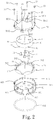
- the pumping piston 61 comprises a plurality of constraint blocks 613 (see Fig. 2 ) respectively coupled to the axially extending guide grooves 22 of the outer cover member 2 (see Fig. 8 ) for vertical movement.
- the pumping piston 61 is adapted for reciprocation in a piston groove 621 of the piston seat 62 axially.
- the pumping piston 61 further comprises an external mounting groove 5 extended around the periphery thereof for the mounting of a first gasket ring 612.
- the piston seat 62 is fastened to the cover member 2 with a plurality of second fasteners 31 or other fastening means, comprising a piston groove 621 that accommodates the pumping piston 61 and allows the pumping piston 61 to reciprocate therein, a second gasket ring 65 mounted around the periphery thereof, and an air-pumping hole 622 cut through a bottom wall thereof (see Fig. 4 and Figs. 7 and 8 ).
- the check valve 64 is mounted in the air-pimping hole 622.
- the guide rods 41 of the first guide block 4 are moved along the first continuous wave-shaped track 51 of the second guide block 5, causing the second guide block 5 and the connected pumping piston 61 to move alternatively up and down along the piston groove 621 of the piston seat 62 (see Figs. 7 and 8 ).
- the pumping piston 61 air is drawn out of the storage container 10 through the air-pimping hole 622 of the piston seat 62, causing reaction of a negative pressure in the storage container 10, and thus, the foods stored in the storage container 10 such as red wine, beverages, fruits, biscuits and other ingredients can be maintained fresh and well protected against oxidation.
- the container cover further comprises a first spring member 63 supported between the pumping piston 61 and the piston groove 621 of the piston seat 62 (see Figs. 7 and 8 ) to balance the axial movement of the pumping piston 61.
- the load In the air-drawing stroke during the reciprocating motion of the piston 61, the load is heavy. On the contrary, in the return action during the reciprocating motion of the piston 61, the load is light. Subject to the arrangement of the first spring member 63, the user's hand can feel smooth when rotating the rotary device (rotary knob) 1.
- an upper rail seat 50 is fastened to the second guide block 5 and the pumping piston 61 by the aforesaid third fasteners 53.
- the upper rail seat 50 defines a second continuous wave-shaped track 501.
- the guide rods 41 of the first guide block 4 are supported between the second continuous wave-shaped track 501 of the upper rail seat 50 and the first continuous wave-shaped track 51 of the second guide block 5 for smooth movement.
- the first continuous wave-shaped track 51 of the second guide block 5 comprises a plurality of low-elevation points 511 and a plurality of high-elevation points 512, wherein each low-elevation point 511 rises gradually to one respective high-elevation point 512; each high-elevation points 512 descends gradually to one respective low-elevation point 511.
- the second continuous wave-shaped track 501 of the upper rail seat 50 comprises a plurality of low-elevation points 5011 and a plurality of high-elevation points 5012, wherein each low-elevation point 5011 rises gradually to one respective high-elevation point 5012; each high-elevation point 5012 descends gradually to one respective low-elevation point 5011.
- the outer cover member 2 further comprises a relief hole 21 (see Fig. 9 ); the inner cover member 3 further comprises a through hole 32 (see Fig. 9 ) corresponding to the relief hole 21.
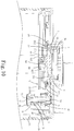
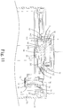
- a relief valve rod 7 is mounted with a gasket ring 71, and movable to close the relief hole 21 of the outer cover member 2 (see Figs. 9 and10) or open relief hole 21 of the outer cover member 2 (see Fig. 11 ).
- a second spring member 70 is mounted between the relief valve rod 7 and the relief hole 21 of the outer cover member 2, and adapted for imparting an elastic restoring energy to the relief valve rod 7 (see Fig.
- the relief valve rod 7 has an internal channel 73 (see Fig. 9 ) extending through opposing top and bottom ends thereof.
- the internal channel 73 has the bottom end thereof disposed in communication with the relief hole 21 of the outer cover member 2, and the opposing top end thereof mounted with a flexible end cap 74 (see Fig. 9 ).
- a flexible end cap 74 will curve down due to the presence of a suction force in the internal channel 73 (see Fig. 10 ).
- the downwardly curving condition of the flexible end cap 74 can be seen, giving a visual negative pressure indication for reference.
- the flexible end cap 74 has a top protrusion 741 made of a different material or in a different color relative to the body of the flexible end cap 74 for easy visual identification of the presence of a negative pressure in the storage container 10.
- dust ring caps 81,82 with respective anti-dust filter meshes 83,84 are respectively mounted in the relief hole 21 of the outer cover member 2 and the air-pimping hole 622 of the piston seat 62, avoiding powder content in the storage container 10 from affecting air tightness or product service life. Further, the dust ring caps 81,82 and the anti-dust filter meshes 83,84 are detachable for easy cleaning or replacement
- the first spring member 63 is eliminated, achieving the same expected effects.
- the relief valve rod 7 is disposed at a different location with the top end thereof facing toward a through hole 12 in the rotary device (rotary knob) 1.
- the piston seat 6 further comprises a relief hole 620; the relief hole 620 of the piston seat 6 can be blocked or opened by the gasket ring 71 of the relief valve rod 7; a second spring member 70 is supported between the relief valve rod 7 and the relief hole 620 of the piston seat 6 to impart an elastic restoring energy to the piston seat 6, forcing the gasket ring 71 of the relief valve rod 7 into abutment against the relief hole 620 of the piston seat 6 after creation of a negative pressure in the storage container 10.
- the relief valve rod 7 has an internal channel 73 extending through opposing top and bottom ends thereof. The bottom end of the internal channel 73 is disposed in communication with the relief hole 620 of the piston seat 62. The opposing top end of the relief valve rod 7 is mounted with a flexible end cap 74.
- the flexible end cap 74 when a negative pressure is created in the storage container 10 after the container cover covered the storage container 10, the flexible end cap 74 will curve down due to a suction force in the internal channel 73 (see Fig. 10 ). The downwardly curving condition of the flexible end cap 74 can be seen, giving a visual negative pressure indication for reference.
- the flexible end cap 74 has a top protrusion 741 made of a different material or in a different color relative to the body of the flexible end cap 74 for easy identification of the presence of a negative pressure in the storage container 10.
- a container cover that facilitates creating negative pressure and long time sealing in accordance with a second embodiment of the present invention is shown.
- the container cover of this second embodiment is substantially similar to the aforesaid first embodiment with the exception that the rotary device 1 in this second embodiment is a motor module.
- the rotary device (motor module) 1 is affixed to the first guide block 4 with fasteners (not shown).
- the mating arrangement between the guide rods 41 of the first guide block 4 and the first continuous wave-shaped track 51 of the second guide block 5 causes the second guide block 5 and the pumping piston 61 to move alternatively up and down in the piston groove 621 of the piston seat 62, thereby drawing air out of the storage container 10 through the air-pimping hole 622 of the piston seat 62, and a negative pressure is thus created in the storage container 10.
- the rotary device (motor module) 1 is electrically connected to a power supply module 12 (for example, battery set).
- the power supply module 12 is electrically coupled to a switch control module 13 that controls on/off of the rotary device (motor module) 1.
Landscapes
- Engineering & Computer Science (AREA)
- Mechanical Engineering (AREA)
- Food Science & Technology (AREA)
- Closures For Containers (AREA)
Abstract
Description
- The present invention relates to negative pressure storage container technology and more particularly, to a container cover that enables a pumping piston to pump air out of a container on which the container cover is covered after the user rotates a rotary device.
-
US Patent Number 9,296,542 - Further, in the use of a conventional mechanical type vacuum storage container, when the internal air of the storage container leaks out, the storage container cannot be automatically inflated. There are electronic type negative pressure storage containers commercially available. However, if the internal air of an electronic type negative pressure storage container leaks out, a vacuum performed again, bringing inconvenience.
- In addition, if the wine in a decanter is not finished soon, it is easy to oxidize and to mature quickly and clumsily, soon deteriorating into a worse state. Further, if a drink in a vessel is not finished, it is pity to discard the drink. Further, people may use a sealing container to store food ingredients. However, because the internal storage chamber of the sealing container is not maintained in a negative pressure status, the sealing container cannot keep the storage food ingredients fresh for long.
- The present invention has been accomplished under the circumstances in view. It is therefore the main object of the present invention to provide a container cover consisting of a rotary device, an outer cover member, an inner cover member, a first guide block, second guide block, a pumping piston and a piston seat, and adapted for covering a storage container. The component parts are so arranged that when the rotary device is driven by a user to rotate the first guide block, guide rods of the first guide block are moved along a first continuous wave-shaped track of the second guide block, causing the second guide block and the pumping piston to move alternatively up and to further pump air out of the storage container through an air-pimping hole of the piston seat to create a negative pressure. Thus, the container cover of the invention has the characteristics of simple structure, space saving a wide application range.
- Further, the container cover can be configured for covering a vacuum storage can, vacuum storage box, vacuum storage bottle, decanter, or any of a variety of storage containers of different shapes and sizes, facilitating creation of a negative pressure in the storage container. When a certain level of negative pressure is created in the storage container, the storage food ingredients and eatable items in the storage container can be maintained fresh, avoiding ruptured storage items due to moisture or oxidation.
- Preferably, the container cover further comprises a relief valve rod. The relief valve rod has the top end thereof capped with a flexible end cap. When a negative pressure is created in the storage container, the flexible end cap will curve down, giving a visual indication of the presence of the negative pressure in the storage container.
-
-
Fig. 1 is an exploded view of a container cover in accordance with a first embodiment of the present invention. -
Fig. 2 is an enlarged view of a part ofFig. 2 . -
Fig. 3 is an oblique bottom elevational view of the container cover in accordance with the first embodiment of the present invention. -
Fig. 4 is a sectional elevational applied view of the first embodiment of the present invention, illustrating the container cover covered a storage container. -
Fig. 5 is an exploded view of the container cover and the storage container in accordance with the first embodiment of the present invention. -
Fig. 6 is an oblique top elevational assembly view ofFig. 5 . -
Fig. 7 is a schematic sectional view of a part of the first embodiment of the present invention, illustrating the guide rods disposed at the low-elevation points of the continuous wave-shaped track. -
Fig. 8 is similar toFig. 7 , illustrating the guide rods disposed at the - high-elevation points of the continuous wave-shaped track. -
Fig. 9 is a schematic sectional view of the first embodiment of the present invention, illustrating the arrangement of the relief valve rod and the surrounding component parts. -
Fig. 10 corresponds toFig. 9 after creation of a negative pressure in the storage container. -
Fig. 11 corresponds toFig. 9 , illustrating the relief valve rod pressed down. -
Fig. 12 is a schematic applied view of the first embodiment of the present invention, illustrating the container cover covered a decanter. -
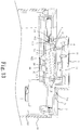
Fig. 13 is a schematic sectional view of the first embodiment of the present invention where the upper rail seat is eliminated. -
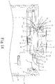
Fig. 14 is a schematic sectional view of the first embodiment of the present invention where the spring member is eliminated. -
Fig. 15 is schematic sectional view of the first embodiment of the present invention, illustrating the position of the relief valve rod changed and the top end of the relief valve rod faced toward the rotary device. -
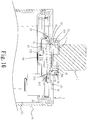
Fig. 16 is a schematic sectional view of a container cover in accordance with a second embodiment of the present invention. -
Fig. 17 is a circuit block diagram of the motor module, power supply module and switch control module of the second embodiment of the present invention. - Referring to
Figs. 1-11 , a container cover that facilitates creating negative pressure and long time sealing in accordance with a first embodiment of the present invention is shown. The container cover of this first embodiment comprises arotary device 1, anouter cover member 2, aninner cover member 3, afirst guide block 4, asecond guide block 5, apumping piston 61, and apiston seat 62, and acheck valve 64. - The
rotary device 1 in this embodiment is a rotary knob rotatably coupled to theouter cover member 2 and fastened to thefirst guide block 4 with a plurality offirst fasteners 11 or other fastening means. - The
outer cover member 2 is fixedly connected to theinner cover member 3 by means of latches (not shown) and matinglatch holes 33 or other fastening means. Further, theouter cover member 2 has a plurality of axially extending guide grooves 22 (seeFig. 8 ). - The
inner cover member 3 is connected to theouter cover member 2 with apacking gasket 30 sealed therebetween so that when theinner cover member 3 is covered with theouter cover member 2 onto an opening 101 of a storage container 10 (seeFigs. 5-8 ). Thestorage container 10 can be kept in an airtight condition. - The
first guide block 4 has a plurality ofguide rods 41. Thesecond guide block 5 has a first continuous wave-shaped track 51 disposed in contact with theguide rods 41. Thus, when thefirst guide block 4 is being rotated with the rotary device (rotary knob) 1, theguide rods 41 are moved along the first continuous wave-shaped track 51 of thesecond guide block 5, causing thesecond guide block 5 to be moved up and down. Further, thesecond guide block 5 fastened to thepumping piston 61 withthird fasteners 53 or other fastening means. - The
pumping piston 61 comprises a plurality of constraint blocks 613 (seeFig. 2 ) respectively coupled to the axially extendingguide grooves 22 of the outer cover member 2 (seeFig. 8 ) for vertical movement. Thepumping piston 61 is adapted for reciprocation in apiston groove 621 of thepiston seat 62 axially. Thepumping piston 61 further comprises anexternal mounting groove 5 extended around the periphery thereof for the mounting of afirst gasket ring 612. - The
piston seat 62 is fastened to thecover member 2 with a plurality ofsecond fasteners 31 or other fastening means, comprising apiston groove 621 that accommodates thepumping piston 61 and allows thepumping piston 61 to reciprocate therein, asecond gasket ring 65 mounted around the periphery thereof, and an air-pumping hole 622 cut through a bottom wall thereof (seeFig. 4 andFigs. 7 and8 ). Thecheck valve 64 is mounted in the air-pimping hole 622. - Thus, when the user operates the rotary device (rotary knob) 1 to rotate the
first guide block 4, theguide rods 41 of thefirst guide block 4 are moved along the first continuous wave-shaped track 51 of thesecond guide block 5, causing thesecond guide block 5 and the connectedpumping piston 61 to move alternatively up and down along thepiston groove 621 of the piston seat 62 (seeFigs. 7 and8 ). During the reciprocating movement of thepumping piston 61, air is drawn out of thestorage container 10 through the air-pimping hole 622 of thepiston seat 62, causing reaction of a negative pressure in thestorage container 10, and thus, the foods stored in thestorage container 10 such as red wine, beverages, fruits, biscuits and other ingredients can be maintained fresh and well protected against oxidation. - The container cover further comprises a
first spring member 63 supported between thepumping piston 61 and thepiston groove 621 of the piston seat 62 (seeFigs. 7 and8 ) to balance the axial movement of thepumping piston 61. - In the air-drawing stroke during the reciprocating motion of the
piston 61, the load is heavy. On the contrary, in the return action during the reciprocating motion of thepiston 61, the load is light. Subject to the arrangement of thefirst spring member 63, the user's hand can feel smooth when rotating the rotary device (rotary knob) 1. - Further, an
upper rail seat 50 is fastened to thesecond guide block 5 and thepumping piston 61 by the aforesaidthird fasteners 53. Theupper rail seat 50 defines a second continuous wave-shapedtrack 501. Theguide rods 41 of thefirst guide block 4 are supported between the second continuous wave-shapedtrack 501 of theupper rail seat 50 and the first continuous wave-shapedtrack 51 of thesecond guide block 5 for smooth movement. - As illustrated in
Fig. 2 , the first continuous wave-shapedtrack 51 of thesecond guide block 5 comprises a plurality of low-elevation points 511 and a plurality of high-elevation points 512, wherein each low-elevation point 511 rises gradually to one respective high-elevation point 512; each high-elevation points 512 descends gradually to one respective low-elevation point 511. - Further, as illustrated in
Fig. 2 , the second continuous wave-shapedtrack 501 of theupper rail seat 50 comprises a plurality of low-elevation points 5011 and a plurality of high-elevation points 5012, wherein each low-elevation point 5011 rises gradually to one respective high-elevation point 5012; each high-elevation point 5012 descends gradually to one respective low-elevation point 5011. - Further, as illustrated in
Figs. 9-11 , theouter cover member 2 further comprises a relief hole 21 (seeFig. 9 ); theinner cover member 3 further comprises a through hole 32 (seeFig. 9 ) corresponding to therelief hole 21. Further, arelief valve rod 7 is mounted with agasket ring 71, and movable to close therelief hole 21 of the outer cover member 2 (seeFigs. 9 and10) oropen relief hole 21 of the outer cover member 2 (seeFig. 11 ). Further, asecond spring member 70 is mounted between therelief valve rod 7 and therelief hole 21 of theouter cover member 2, and adapted for imparting an elastic restoring energy to the relief valve rod 7 (seeFig. 10 ) to force thegasket ring 71 against therelief hole 21 of theouter cover member 2 when the container cover is capped on thestorage container 10 and a negative pressure is created in thestorage container 10. Further, when therelief valve rod 7 is pressed down by an external force (seeFig. 11 ), a gap is created between thegasket ring 71 and therelief hole 21 of theouter cover member 2 for discharge of the negative pressure. When the applied force is released from therelief valve rod 7, the elastic restoring energy of thesecond spring member 70 immediately pushes therelief valve rod 7 upward (seeFig. 9 ), forcing thegasket ring 71 to stop therelief hole 21. Further, therelief valve rod 7 has an internal channel 73 (seeFig. 9 ) extending through opposing top and bottom ends thereof. Theinternal channel 73 has the bottom end thereof disposed in communication with therelief hole 21 of theouter cover member 2, and the opposing top end thereof mounted with a flexible end cap 74 (seeFig. 9 ). Thus, when a negative pressure is created in thestorage container 10 after the container cover covered thestorage container 10, theflexible end cap 74 will curve down due to the presence of a suction force in the internal channel 73 (seeFig. 10 ). The downwardly curving condition of theflexible end cap 74 can be seen, giving a visual negative pressure indication for reference. Theflexible end cap 74 has atop protrusion 741 made of a different material or in a different color relative to the body of theflexible end cap 74 for easy visual identification of the presence of a negative pressure in thestorage container 10. - Further, as illustrated in
Fig. 1 andFig. 9 , dust ring caps 81,82 with respective anti-dust filter meshes 83,84 are respectively mounted in therelief hole 21 of theouter cover member 2 and the air-pimpinghole 622 of thepiston seat 62, avoiding powder content in thestorage container 10 from affecting air tightness or product service life. Further, the dust ring caps 81,82 and the anti-dust filter meshes 83,84 are detachable for easy cleaning or replacement - Referring to
Fig. 13 , in a modification of the first embodiment of the present invention, the aforesaidupper rail seat 50 is eliminated, achieving the same expected effects. - Referring to
Fig. 14 , in another modification of the first embodiment of the present invention, thefirst spring member 63 is eliminated, achieving the same expected effects. - Referring to
Fig. 15 , in still another modification of the first embodiment of the present invention, therelief valve rod 7 is disposed at a different location with the top end thereof facing toward a throughhole 12 in the rotary device (rotary knob) 1. In this embodiment, the piston seat 6 further comprises arelief hole 620; therelief hole 620 of the piston seat 6 can be blocked or opened by thegasket ring 71 of therelief valve rod 7; asecond spring member 70 is supported between therelief valve rod 7 and therelief hole 620 of the piston seat 6 to impart an elastic restoring energy to the piston seat 6, forcing thegasket ring 71 of therelief valve rod 7 into abutment against therelief hole 620 of the piston seat 6 after creation of a negative pressure in thestorage container 10. Further, when therelief valve rod 7 is being held down by an external pressure, a gap is created between thegasket ring 71 and therelief hole 620 of the piston seat 6 for discharging air pressure. When released the downward pressure from therelief valve rod 7, the elastic restoring energy of thesecond spring member 70 immediately pushes therelief valve rod 7 upward, forcing thegasket ring 71 into abutment against therelief hole 620 again. Therelief valve rod 7 has aninternal channel 73 extending through opposing top and bottom ends thereof. The bottom end of theinternal channel 73 is disposed in communication with therelief hole 620 of thepiston seat 62. The opposing top end of therelief valve rod 7 is mounted with aflexible end cap 74. Thus, when a negative pressure is created in thestorage container 10 after the container cover covered thestorage container 10, theflexible end cap 74 will curve down due to a suction force in the internal channel 73 (seeFig. 10 ). The downwardly curving condition of theflexible end cap 74 can be seen, giving a visual negative pressure indication for reference. Theflexible end cap 74 has atop protrusion 741 made of a different material or in a different color relative to the body of theflexible end cap 74 for easy identification of the presence of a negative pressure in thestorage container 10. - Referring to
Figs. 16 and17 , a container cover that facilitates creating negative pressure and long time sealing in accordance with a second embodiment of the present invention is shown. The container cover of this second embodiment is substantially similar to the aforesaid first embodiment with the exception that therotary device 1 in this second embodiment is a motor module. The rotary device (motor module) 1 is affixed to thefirst guide block 4 with fasteners (not shown). When the rotary device (motor module) 1 is driven to rotate thefirst guide block 4, the mating arrangement between theguide rods 41 of thefirst guide block 4 and the first continuous wave-shapedtrack 51 of thesecond guide block 5 causes thesecond guide block 5 and thepumping piston 61 to move alternatively up and down in thepiston groove 621 of thepiston seat 62, thereby drawing air out of thestorage container 10 through the air-pimpinghole 622 of thepiston seat 62, and a negative pressure is thus created in thestorage container 10. - Further, as illustrated in
Fig. 17 , the rotary device (motor module) 1 is electrically connected to a power supply module 12 (for example, battery set). Thepower supply module 12 is electrically coupled to aswitch control module 13 that controls on/off of the rotary device (motor module) 1. - The other structural details and technical features are same as the aforesaid first embodiment. The only difference between the aforesaid first embodiment and this second embodiment is the use of a motor module for the
rotary device 1. Since the contents of the second embodiment are the same as those of the first embodiment, we do not repeat them. - In conclusion, the invention has the features and effects as follows:
- 1. When rotating the
rotary device 1, the mating arrangement between theguide rods 41 of thefirst guide block 4 and the first continuous wave-shapedtrack 51 of thesecond guide block 5 causes thesecond guide block 5 and thepumping piston 61 to move alternatively up and down in thepiston groove 621 of thepiston seat 62, thereby drawing air out of thestorage container 10 to create a negative pressure is thus created in thestorage container 10. Thus, the container cover of the invention has the characteristics of simple structure, space saving a wide application range. - 2. The container cover can be configured for covering a vacuum storage can, vacuum storage box, vacuum storage bottle, decanter, or any of a variety of storage containers of different shapes and sizes.
Fig. 12 illustrates the container cover of the present invention capped on a decanter 10'. - 3. When a certain level of negative pressure is created in the
storage container 10, the storage food ingredients and eatable items in thestorage container 10 can be maintained fresh, avoiding ruptured storage items due to moisture or oxidation. - 4. When a negative pressure is created in the
storage container 10, theflexible end cap 74 of therelief valve rod 7 will curve down, giving a visual indication of the presence of a negative pressure in thestorage container 10; theflexible end cap 74 can be configured to provide atop protrusion 741 that is at the center of the top surface of theflexible end cap 74 and made of a different material in a different color relative to theflexible end cap 74, enhancing the negative pressure identification indication effect.
Claims (12)
- A container cover, comprising a rotary device, an outer cover member, an inner cover member, a first guide block, a second guide block, upper rail seat, a pumping piston, a piston seat, and a check valve, wherein:said rotary device is rotatably coupled to said outer cover member and fixedly connected with said first guide block;said outer cover member is fixedly connected to said inner cover member, said outer cover member comprising a plurality of axially extending guide grooves;said inner cover member is mounted with a packing gasket, said packing gasket being set between said inner cover member and said outer cover member and adapted for sealing a container in an airtight manner when said outer cover member is covered with said inner cover member on said container;said first guide block comprises a plurality of guide rods;said second guide block is fixedly fastened to said pumping piston, comprising a first continuous wave-shaped track disposed in contact with said guide rods at a bottom side for causing said guide rods to move along said first continuous wave-shaped track of said second guide block and said second guide block to move up and down when said first guide block is rotated by said rotary device, said first continuous wave-shaped track of said second guide block comprising a plurality of low-elevation points and a plurality of high-elevation points, each said low-elevation point of said first continuous wave-shaped track rising gradually to one respective said high-elevation points of said first continuous wave-shaped track, each said high-elevation point of said first continuous wave-shaped track descending gradually to one respective said low-elevation point of said first continuous wave-shaped track;said upper rail seat is fixedly fastened to said second guide block and said pumping piston, comprising a second continuous wave-shaped track disposed in contact with said guide rods of said first guide block at a top side, said second continuous wave-shaped track of said upper rail seat comprising a plurality of low-elevation points and a plurality of high-elevation points, each said low-elevation point of said second continuous wave-shaped track rising gradually to one respective said high-elevation points of said second continuous wave-shaped track, each said high-elevation point of said second continuous wave-shaped track descending gradually to one respective said low-elevation point of said second continuous wave-shaped track;said pumping piston is adapted for reciprocation in a piston groove of said piston seat axially, comprising a plurality of constraint blocks respectively coupled to said axially extending guide grooves of said outer cover member for vertical movement and an external mounting groove extended around the periphery thereof and mounted with a first gasket ring;said piston seat is fixedly fastened to said cover member, comprising a piston groove that accommodates said pumping piston and allows said pumping piston to reciprocate therein, a second gasket ring mounted around the periphery thereof, and an air-pumping hole cut through a bottom wall thereof;said check valve is mounted in said air-pimping hole of said piston seat;when said rotary device is driven by an external force to rotate said first guide block, said guide rods are moved along said first continuous wave-shaped track, causing said second guide block and said pumping piston to move alternatively up and down in said piston groove of said piston seat and to further pump air out of said container through said air-pumping hole of said piston seat.
- The container cover as claimed in claim 1, wherein said outer cover member further comprises a relief hole; said inner cover member further comprises a through hole corresponding to said relief hole; the container cover further comprises a relief valve rod mounted with a gasket ring and alternatively movable back and forth to close or open said relief hole of said outer cover member, a second spring member mounted between said relief valve rod and said relief hole of said outer cover member and adapted for imparting an elastic restoring energy to said relief valve rod to force the said gasket ring at said relief valve rod into tightly abutment against said relief hole of said outer cover member when said container cover is capped on said container and a negative pressure is created in said container; when said relief valve rod is pressed down by an external force, a gap is created between the said gasket ring at said relief valve rod and said relief hole of said outer cover member for discharge of said negative pressure. when the applied force is released from the said relief valve rod at said relief valve rod, the elastic restoring energy of said second spring member immediately pushes said relief valve rod upward to force the said gasket ring at said relief valve rod to stop said relief hole, said relief valve rod having an internal channel extending through opposing top and bottom ends thereof, said internal channel having the bottom end thereof disposed in communication with said relief hole of said outer cover member and the opposing top end thereof mounted with a flexible end cap, said flexible end cap being caused to curve down when a negative pressure is created in said container after said container cover covered said container, said flexible end cap having a top protrusion made of a different material n a different color relative to the body of said flexible end cap for quick visual identification of the presence of a negative pressure in said container.
- The container cover as claimed in claim 1, wherein said piston seat further comprises a relief hole; the container cover further comprises a relief valve rod mounted with a gasket ring and alternatively movable back and forth to close or open said relief hole of said outer cover member, a second spring member mounted between said relief valve rod and said relief hole of said piston seat and adapted for imparting an elastic restoring energy to said relief valve rod to force the said gasket ring at said relief valve rod into tightly abutment against said relief hole of said piston seat when said container cover is capped on said container and a negative pressure is created in said container; when said relief valve rod is pressed down by an external force, a gap is created between the said gasket ring at said relief valve rod and said relief hole of said piston seat for discharge of said negative pressure. when the applied force is released from the said relief valve rod at said relief valve rod, the elastic restoring energy of said second spring member immediately pushes said relief valve rod upward to force the said gasket ring at said relief valve rod to stop said relief hole, said relief valve rod having an internal channel extending through opposing top and bottom ends thereof, said internal channel having the bottom end thereof disposed in communication with said relief hole of said piston seat and the opposing top end thereof mounted with a flexible end cap, said flexible end cap being caused to curve down when a negative pressure is created in said container after said container cover covered said container, said flexible end cap having a top protrusion made of a different material n a different color relative to the body of said flexible end cap for quick visual identification of the presence of a negative pressure in said container.
- The container cover as claimed in claim 1, wherein said rotary device comprises a motor module coupled with said first guide block, a power supply module electrically coupled to said motor module, and a switch control module electrically coupled to said power supply module for controlling on/off of said motor module.
- A container cover, comprising a rotary device, an outer cover member, an inner cover member, a first guide block, a second guide block, a pumping piston, a piston seat, a check valve and a first spring member, wherein:said rotary device is rotatably coupled to said outer cover member and fixedly connected with said first guide block;said outer cover member is fixedly connected to said inner cover member, said outer cover member comprising a plurality of axially extending guide grooves;said inner cover member is mounted with a packing gasket, said packing gasket being set between said inner cover member and said outer cover member and adapted for sealing a container in an airtight manner when said outer cover member is covered with said inner cover member on said container;said first guide block comprises a plurality of guide rods;said second guide block is fixedly fastened to said pumping piston, comprising a first continuous wave-shaped track disposed in contact with said guide rods at a bottom side for causing said guide rods to move along said first continuous wave-shaped track of said second guide block and said second guide block to move up and down when said first guide block is rotated by said rotary device, said first continuous wave-shaped track of said second guide block comprising a plurality of low-elevation points and a plurality of high-elevation points, each said low-elevation point of said first continuous wave-shaped track rising gradually to one respective said high-elevation points of said first continuous wave-shaped track, each said high-elevation point of said first continuous wave-shaped track descending gradually to one respective said low-elevation point of said first continuous wave-shaped track;said pumping piston is adapted for reciprocation in a piston groove of said piston seat axially, comprising a plurality of constraint blocks respectively coupled to said axially extending guide grooves of said outer cover member for vertical movement and an external mounting groove extended around the periphery thereof and mounted with a first gasket ring;said piston seat is fixedly fastened to said cover member, comprising a piston groove that accommodates said pumping piston and allows said pumping piston to reciprocate therein, a second gasket ring mounted around the periphery thereof, and an air-pumping hole cut through a bottom wall thereof;said check valve is mounted in said air-pimping hole of said piston seat;said first spring member is mounted between said piston seat and said pumping piston;when said rotary device is driven by an external force to rotate said first guide block, said guide rods are moved along said first continuous wave-shaped track, causing said second guide block and said pumping piston to move alternatively up and down in said piston groove of said piston seat and to further pump air out of said container through said air-pimping hole of said piston seat.
- The container cover as claimed in claim 5, wherein said outer cover member further comprises a relief hole; said inner cover member further comprises a through hole corresponding to said relief hole; the container cover further comprises a relief valve rod mounted with a gasket ring and alternatively movable back and forth to close or open said relief hole of said outer cover member, a second spring member mounted between said relief valve rod and said relief hole of said outer cover member and adapted for imparting an elastic restoring energy to said relief valve rod to force the said gasket ring at said relief valve rod into tightly abutment against said relief hole of said outer cover member when said container cover is capped on said container and a negative pressure is created in said container; when said relief valve rod is pressed down by an external force, a gap is created between the said gasket ring at said relief valve rod and said relief hole of said outer cover member for discharge of said negative pressure. when the applied force is released from the said relief valve rod at said relief valve rod, the elastic restoring energy of said second spring member immediately pushes said relief valve rod upward to force the said gasket ring at said relief valve rod to stop said relief hole, said relief valve rod having an internal channel extending through opposing top and bottom ends thereof, said internal channel having the bottom end thereof disposed in communication with said relief hole of said outer cover member and the opposing top end thereof mounted with a flexible end cap, said flexible end cap being caused to curve down when a negative pressure is created in said container after said container cover covered said container, said flexible end cap having a top protrusion made of a different material n a different color relative to the body of said flexible end cap for quick visual identification of the presence of a negative pressure in said container.
- The container cover as claimed in claim 5, wherein said piston seat further comprises a relief hole; the container cover further comprises a relief valve rod mounted with a gasket ring and alternatively movable back and forth to close or open said relief hole of said outer cover member, a second spring member mounted between said relief valve rod and said relief hole of said piston seat and adapted for imparting an elastic restoring energy to said relief valve rod to force the said gasket ring at said relief valve rod into tightly abutment against said relief hole of said piston seat when said container cover is capped on said container and a negative pressure is created in said container; when said relief valve rod is pressed down by an external force, a gap is created between the said gasket ring at said relief valve rod and said relief hole of said piston seat for discharge of said negative pressure. when the applied force is released from the said relief valve rod at said relief valve rod, the elastic restoring energy of said second spring member immediately pushes said relief valve rod upward to force the said gasket ring at said relief valve rod to stop said relief hole, said relief valve rod having an internal channel extending through opposing top and bottom ends thereof, said internal channel having the bottom end thereof disposed in communication with said relief hole of said piston seat and the opposing top end thereof mounted with a flexible end cap, said flexible end cap being caused to curve down when a negative pressure is created in said container after said container cover covered said container, said flexible end cap having a top protrusion made of a different material n a different color relative to the body of said flexible end cap for quick visual identification of the presence of a negative pressure in said container.
- The container cover as claimed in claim 5, wherein said rotary device comprises a motor module coupled with said first guide block, a power supply module electrically coupled to said motor module, and a switch control module electrically coupled to said power supply module for controlling on/off of said motor module.
- A container cover, comprising a rotary device, an outer cover member, an inner cover member, a first guide block, a second guide block, a pumping piston, a piston seat, a check valve and a first spring member, wherein:said rotary device is rotatably coupled to said outer cover member and fixedly connected with said first guide block;said outer cover member is fixedly connected to said inner cover member, said outer cover member comprising a plurality of axially extending guide grooves;said inner cover member is mounted with a packing gasket, said packing gasket being set between said inner cover member and said outer cover member and adapted for sealing a container in an airtight manner when said outer cover member is covered with said inner cover member on said container;said first guide block comprises a plurality of guide rods;said second guide block is fixedly fastened to said pumping piston, comprising a first continuous wave-shaped track disposed in contact with said guide rods at a bottom side for causing said guide rods to move along said first continuous wave-shaped track of said second guide block and said second guide block to move up and down when said first guide block is rotated by said rotary device, said first continuous wave-shaped track of said second guide block comprising a plurality of low-elevation points and a plurality of high-elevation points, each said low-elevation point of said first continuous wave-shaped track rising gradually to one respective said high-elevation points of said first continuous wave-shaped track, each said high-elevation point of said first continuous wave-shaped track descending gradually to one respective said low-elevation point of said first continuous wave-shaped track;said upper rail seat is fixedly fastened to said second guide block and said pumping piston, comprising a second continuous wave-shaped track disposed in contact with said guide rods of said first guide block at a top side, said second continuous wave-shaped track of said upper rail seat comprising a plurality of low-elevation points and a plurality of high-elevation points, each said low-elevation point of said second continuous wave-shaped track rising gradually to one respective said high-elevation points of said second continuous wave-shaped track, each said high-elevation point of said second continuous wave-shaped track descending gradually to one respective said low-elevation point of said second continuous wave-shaped track;said pumping piston is adapted for reciprocation in a piston groove of said piston seat axially, comprising a plurality of constraint blocks respectively coupled to said axially extending guide grooves of said outer cover member for vertical movement and an external mounting groove extended around the periphery thereof and mounted with a first gasket ring;said piston seat is fixedly fastened to said cover member, comprising a piston groove that accommodates said pumping piston and allows said pumping piston to reciprocate therein, a second gasket ring mounted around the periphery thereof, and an air-pumping hole cut through a bottom wall thereof;said check valve is mounted in said air-pimping hole of said piston seat;said first spring member is mounted between said piston seat and said pumping piston;when said rotary device is driven by an external force to rotate said first guide block, said guide rods are moved along said first continuous wave-shaped track, causing said second guide block and said pumping piston to move alternatively up and down in said piston groove of said piston seat and to further pump air out of said container through said air-pimping hole of said piston seat.
- The container cover as claimed in claim 9, wherein said outer cover member further comprises a relief hole; said inner cover member further comprises a through hole corresponding to said relief hole; the container cover further comprises a relief valve rod mounted with a gasket ring and alternatively movable back and forth to close or open said relief hole of said outer cover member, a second spring member mounted between said relief valve rod and said relief hole of said outer cover member and adapted for imparting an elastic restoring energy to said relief valve rod to force the said gasket ring at said relief valve rod into tightly abutment against said relief hole of said outer cover member when said container cover is capped on said container and a negative pressure is created in said container; when said relief valve rod is pressed down by an external force, a gap is created between the said gasket ring at said relief valve rod and said relief hole of said outer cover member for discharge of said negative pressure, when the applied force is released from the said relief valve rod at said relief valve rod, the elastic restoring energy of said second spring member immediately pushes said relief valve rod upward to force the said gasket ring at said relief valve rod to stop said relief hole, said relief valve rod having an internal channel extending through opposing top and bottom ends thereof, said internal channel having the bottom end thereof disposed in communication with said relief hole of said outer cover member and the opposing top end thereof mounted with a flexible end cap, said flexible end cap being caused to curve down when a negative pressure is created in said container after said container cover covered said container, said flexible end cap having a top protrusion made of a different material n a different color relative to the body of said flexible end cap for quick visual identification of the presence of a negative pressure in said container.
- The container cover as claimed in claim 9, wherein said piston seat further comprises a relief hole; the container cover further comprises a relief valve rod mounted with a gasket ring and alternatively movable back and forth to close or open said relief hole of said outer cover member, a second spring member mounted between said relief valve rod and said relief hole of said piston seat and adapted for imparting an elastic restoring energy to said relief valve rod to force the said gasket ring at said relief valve rod into tightly abutment against said relief hole of said piston seat when said container cover is capped on said container and a negative pressure is created in said container; when said relief valve rod is pressed down by an external force, a gap is created between the said gasket ring at said relief valve rod and said relief hole of said piston seat for discharge of said negative pressure. when the applied force is released from the said relief valve rod at said relief valve rod, the elastic restoring energy of said second spring member immediately pushes said relief valve rod upward to force the said gasket ring at said relief valve rod to stop said relief hole, said relief valve rod having an internal channel extending through opposing top and bottom ends thereof, said internal channel having the bottom end thereof disposed in communication with said relief hole of said piston seat and the opposing top end thereof mounted with a flexible end cap, said flexible end cap being caused to curve down when a negative pressure is created in said container after said container cover covered said container, said flexible end cap having a top protrusion made of a different material n a different color relative to the body of said flexible end cap for quick visual identification of the presence of a negative pressure in said container.
- The container cover as claimed in claim 9, wherein said rotary device comprises a motor module coupled with said first guide block, a power supply module electrically coupled to said motor module, and a switch control module electrically coupled to said power supply module for controlling on/off of said motor module.
Applications Claiming Priority (1)
| Application Number | Priority Date | Filing Date | Title |
|---|---|---|---|
| TW106203394U TWM542630U (en) | 2017-03-10 | 2017-03-10 | Container cover of conveniently manufacturing negative pressure and long term sealing |
Publications (2)
| Publication Number | Publication Date |
|---|---|
| EP3372526A1 true EP3372526A1 (en) | 2018-09-12 |
| EP3372526B1 EP3372526B1 (en) | 2022-10-12 |
Family
ID=59689443
Family Applications (1)
| Application Number | Title | Priority Date | Filing Date |
|---|---|---|---|
| EP18250006.6A Active EP3372526B1 (en) | 2017-03-10 | 2018-01-31 | Container cover that facilitates creating negative pressure and long time sealing |
Country Status (4)
| Country | Link |
|---|---|
| EP (1) | EP3372526B1 (en) |
| AU (1) | AU2018100135A4 (en) |
| ES (1) | ES2931073T3 (en) |
| TW (1) | TWM542630U (en) |
Cited By (3)
| Publication number | Priority date | Publication date | Assignee | Title |
|---|---|---|---|---|
| CN108861041A (en) * | 2018-09-12 | 2018-11-23 | 深圳市集品实业有限公司 | A kind of switching mechanism and red wine machine |
| WO2022239973A1 (en) * | 2021-05-14 | 2022-11-17 | 정병찬 | Cover and sealed container comprising same |
| CN119460424A (en) * | 2024-11-27 | 2025-02-18 | 贵州黔西中水发电有限公司 | Sample barrel |
Families Citing this family (4)
| Publication number | Priority date | Publication date | Assignee | Title |
|---|---|---|---|---|
| CN111109998B (en) * | 2018-10-31 | 2022-10-21 | 浙江苏泊尔家电制造有限公司 | Cooking appliance and pressure control method for cooking appliance |
| CN112623493B (en) * | 2020-12-04 | 2022-10-11 | 浙江千翊科技有限公司 | Fresh-keeping box |
| TWI880654B (en) * | 2024-03-05 | 2025-04-11 | 飛綠股份有限公司 | Manual vacuum container |
| CN222523070U (en) * | 2024-06-12 | 2025-02-25 | 江门市南光电器实业有限公司 | Thermal insulation appliance |
Citations (5)
| Publication number | Priority date | Publication date | Assignee | Title |
|---|---|---|---|---|
| EP1350737A1 (en) * | 2002-03-27 | 2003-10-08 | Tai-In Chang | Container assembly having a cover cap provided with a pump member to pump out air from the container |
| US20050115632A1 (en) * | 2003-12-02 | 2005-06-02 | Shlomo Haimi | Vacuum bottle cap |
| US20050244293A1 (en) * | 2004-04-28 | 2005-11-03 | Lin Yvonne S | Vacuum canister |
| US9296542B2 (en) | 2014-06-23 | 2016-03-29 | Shin Hung Yih Technology Co. Ltd. | Vacuum storage container |
| CN206842124U (en) * | 2017-03-17 | 2018-01-05 | 鑫宏益科技有限公司 | Convenient manufacture container negative pressure and for a long time container cover of sealing |
-
2017
- 2017-03-10 TW TW106203394U patent/TWM542630U/en unknown
-
2018
- 2018-01-31 AU AU2018100135A patent/AU2018100135A4/en not_active Expired
- 2018-01-31 ES ES18250006T patent/ES2931073T3/en active Active
- 2018-01-31 EP EP18250006.6A patent/EP3372526B1/en active Active
Patent Citations (5)
| Publication number | Priority date | Publication date | Assignee | Title |
|---|---|---|---|---|
| EP1350737A1 (en) * | 2002-03-27 | 2003-10-08 | Tai-In Chang | Container assembly having a cover cap provided with a pump member to pump out air from the container |
| US20050115632A1 (en) * | 2003-12-02 | 2005-06-02 | Shlomo Haimi | Vacuum bottle cap |
| US20050244293A1 (en) * | 2004-04-28 | 2005-11-03 | Lin Yvonne S | Vacuum canister |
| US9296542B2 (en) | 2014-06-23 | 2016-03-29 | Shin Hung Yih Technology Co. Ltd. | Vacuum storage container |
| CN206842124U (en) * | 2017-03-17 | 2018-01-05 | 鑫宏益科技有限公司 | Convenient manufacture container negative pressure and for a long time container cover of sealing |
Cited By (3)
| Publication number | Priority date | Publication date | Assignee | Title |
|---|---|---|---|---|
| CN108861041A (en) * | 2018-09-12 | 2018-11-23 | 深圳市集品实业有限公司 | A kind of switching mechanism and red wine machine |
| WO2022239973A1 (en) * | 2021-05-14 | 2022-11-17 | 정병찬 | Cover and sealed container comprising same |
| CN119460424A (en) * | 2024-11-27 | 2025-02-18 | 贵州黔西中水发电有限公司 | Sample barrel |
Also Published As
| Publication number | Publication date |
|---|---|
| EP3372526B1 (en) | 2022-10-12 |
| ES2931073T3 (en) | 2022-12-23 |
| AU2018100135A4 (en) | 2018-03-01 |
| TWM542630U (en) | 2017-06-01 |
Similar Documents
| Publication | Publication Date | Title |
|---|---|---|
| US10654639B2 (en) | Container cover that facilitates creating negative pressure and long time sealing | |
| EP3372526B1 (en) | Container cover that facilitates creating negative pressure and long time sealing | |
| US10138046B2 (en) | Negative pressure storage container | |
| KR101267966B1 (en) | Operation button have airless pump have cosmetic case | |
| US20080135126A1 (en) | Motorized vacuum/pressure marinating food and storage container | |
| EP1689645B1 (en) | Pump bottle cap | |
| KR101831501B1 (en) | One turn actuated duration spray pump mechanism | |
| KR101161732B1 (en) | Vacuum Generating Apparatus and Vacuum Container Using the Same | |
| KR101202284B1 (en) | A airless pump and airless pump have cosmetic case | |
| KR200370575Y1 (en) | A structure of casmetic case which is possible for discharge standard capacity of high viscosity cosmetic | |
| KR101356989B1 (en) | Vacuum compression apparatus using handmixer | |
| US9067723B2 (en) | Container for storing foods | |
| EP3369354B1 (en) | Negative pressure storage container | |
| KR200485788Y1 (en) | Negative pressure storage container | |
| EP3184461B1 (en) | Bottle cover and bottle with the bottle cover | |
| CN208587270U (en) | A kind of portable vacuum device | |
| KR200362416Y1 (en) | A structure of casmetic case which is possible for discharge standard capacity of high viscosity cosmetic | |
| KR101084365B1 (en) | Storage container | |
| KR200465229Y1 (en) | A airless pump have cosmetic case of pumping apparatus | |
| KR200388134Y1 (en) | Electromotive cosmetic case | |
| JP6088615B2 (en) | Continuous spray pump mechanism operating at one revolution | |
| CN221520600U (en) | Rotary movable cover plate with sealing structure and storage box thereof | |
| JPH081172B2 (en) | Hand-operated vacuum pump that reduces the pressure inside the container | |
| KR20140008179A (en) | Vaccum pump and vaccum container having the same | |
| EP2030943A1 (en) | Liquid dispenser |
Legal Events
| Date | Code | Title | Description |
|---|---|---|---|
| PUAI | Public reference made under article 153(3) epc to a published international application that has entered the european phase |
Free format text: ORIGINAL CODE: 0009012 |
|
| STAA | Information on the status of an ep patent application or granted ep patent |
Free format text: STATUS: THE APPLICATION HAS BEEN PUBLISHED |
|
| AK | Designated contracting states |
Kind code of ref document: A1 Designated state(s): AL AT BE BG CH CY CZ DE DK EE ES FI FR GB GR HR HU IE IS IT LI LT LU LV MC MK MT NL NO PL PT RO RS SE SI SK SM TR |
|
| AX | Request for extension of the european patent |
Extension state: BA ME |
|
| STAA | Information on the status of an ep patent application or granted ep patent |
Free format text: STATUS: REQUEST FOR EXAMINATION WAS MADE |
|
| 17P | Request for examination filed |
Effective date: 20190311 |
|
| RBV | Designated contracting states (corrected) |
Designated state(s): AL AT BE BG CH CY CZ DE DK EE ES FI FR GB GR HR HU IE IS IT LI LT LU LV MC MK MT NL NO PL PT RO RS SE SI SK SM TR |
|
| RIN1 | Information on inventor provided before grant (corrected) |
Inventor name: YI-HUNG, HO |
|
| RAP1 | Party data changed (applicant data changed or rights of an application transferred) |
Owner name: SHIN HUNG YIH TECHNOLOGY CO., LTD. |
|
| STAA | Information on the status of an ep patent application or granted ep patent |
Free format text: STATUS: EXAMINATION IS IN PROGRESS |
|
| 17Q | First examination report despatched |
Effective date: 20210611 |
|
| GRAP | Despatch of communication of intention to grant a patent |
Free format text: ORIGINAL CODE: EPIDOSNIGR1 |
|
| STAA | Information on the status of an ep patent application or granted ep patent |
Free format text: STATUS: GRANT OF PATENT IS INTENDED |
|
| INTG | Intention to grant announced |
Effective date: 20220531 |
|
| GRAS | Grant fee paid |
Free format text: ORIGINAL CODE: EPIDOSNIGR3 |
|
| GRAA | (expected) grant |
Free format text: ORIGINAL CODE: 0009210 |
|
| STAA | Information on the status of an ep patent application or granted ep patent |
Free format text: STATUS: THE PATENT HAS BEEN GRANTED |
|
| AK | Designated contracting states |
Kind code of ref document: B1 Designated state(s): AL AT BE BG CH CY CZ DE DK EE ES FI FR GB GR HR HU IE IS IT LI LT LU LV MC MK MT NL NO PL PT RO RS SE SI SK SM TR |
|
| REG | Reference to a national code |
Ref country code: GB Ref legal event code: FG4D |
|
| REG | Reference to a national code |
Ref country code: CH Ref legal event code: EP |
|
| REG | Reference to a national code |
Ref country code: DE Ref legal event code: R096 Ref document number: 602018041636 Country of ref document: DE |
|
| REG | Reference to a national code |
Ref country code: IE Ref legal event code: FG4D |
|
| REG | Reference to a national code |
Ref country code: AT Ref legal event code: REF Ref document number: 1524061 Country of ref document: AT Kind code of ref document: T Effective date: 20221115 |
|
| REG | Reference to a national code |
Ref country code: NL Ref legal event code: FP |
|
| REG | Reference to a national code |
Ref country code: ES Ref legal event code: FG2A Ref document number: 2931073 Country of ref document: ES Kind code of ref document: T3 Effective date: 20221223 |
|
| REG | Reference to a national code |
Ref country code: LT Ref legal event code: MG9D |
|
| REG | Reference to a national code |
Ref country code: AT Ref legal event code: MK05 Ref document number: 1524061 Country of ref document: AT Kind code of ref document: T Effective date: 20221012 |
|
| PG25 | Lapsed in a contracting state [announced via postgrant information from national office to epo] |
Ref country code: SE Free format text: LAPSE BECAUSE OF FAILURE TO SUBMIT A TRANSLATION OF THE DESCRIPTION OR TO PAY THE FEE WITHIN THE PRESCRIBED TIME-LIMIT Effective date: 20221012 Ref country code: PT Free format text: LAPSE BECAUSE OF FAILURE TO SUBMIT A TRANSLATION OF THE DESCRIPTION OR TO PAY THE FEE WITHIN THE PRESCRIBED TIME-LIMIT Effective date: 20230213 Ref country code: NO Free format text: LAPSE BECAUSE OF FAILURE TO SUBMIT A TRANSLATION OF THE DESCRIPTION OR TO PAY THE FEE WITHIN THE PRESCRIBED TIME-LIMIT Effective date: 20230112 Ref country code: LT Free format text: LAPSE BECAUSE OF FAILURE TO SUBMIT A TRANSLATION OF THE DESCRIPTION OR TO PAY THE FEE WITHIN THE PRESCRIBED TIME-LIMIT Effective date: 20221012 Ref country code: FI Free format text: LAPSE BECAUSE OF FAILURE TO SUBMIT A TRANSLATION OF THE DESCRIPTION OR TO PAY THE FEE WITHIN THE PRESCRIBED TIME-LIMIT Effective date: 20221012 Ref country code: AT Free format text: LAPSE BECAUSE OF FAILURE TO SUBMIT A TRANSLATION OF THE DESCRIPTION OR TO PAY THE FEE WITHIN THE PRESCRIBED TIME-LIMIT Effective date: 20221012 |
|
| PGFP | Annual fee paid to national office [announced via postgrant information from national office to epo] |
Ref country code: FR Payment date: 20230113 Year of fee payment: 6 Ref country code: ES Payment date: 20230206 Year of fee payment: 6 Ref country code: CH Payment date: 20230126 Year of fee payment: 6 |
|
| PG25 | Lapsed in a contracting state [announced via postgrant information from national office to epo] |
Ref country code: RS Free format text: LAPSE BECAUSE OF FAILURE TO SUBMIT A TRANSLATION OF THE DESCRIPTION OR TO PAY THE FEE WITHIN THE PRESCRIBED TIME-LIMIT Effective date: 20221012 Ref country code: PL Free format text: LAPSE BECAUSE OF FAILURE TO SUBMIT A TRANSLATION OF THE DESCRIPTION OR TO PAY THE FEE WITHIN THE PRESCRIBED TIME-LIMIT Effective date: 20221012 Ref country code: LV Free format text: LAPSE BECAUSE OF FAILURE TO SUBMIT A TRANSLATION OF THE DESCRIPTION OR TO PAY THE FEE WITHIN THE PRESCRIBED TIME-LIMIT Effective date: 20221012 Ref country code: IS Free format text: LAPSE BECAUSE OF FAILURE TO SUBMIT A TRANSLATION OF THE DESCRIPTION OR TO PAY THE FEE WITHIN THE PRESCRIBED TIME-LIMIT Effective date: 20230212 Ref country code: HR Free format text: LAPSE BECAUSE OF FAILURE TO SUBMIT A TRANSLATION OF THE DESCRIPTION OR TO PAY THE FEE WITHIN THE PRESCRIBED TIME-LIMIT Effective date: 20221012 Ref country code: GR Free format text: LAPSE BECAUSE OF FAILURE TO SUBMIT A TRANSLATION OF THE DESCRIPTION OR TO PAY THE FEE WITHIN THE PRESCRIBED TIME-LIMIT Effective date: 20230113 |
|
| PGFP | Annual fee paid to national office [announced via postgrant information from national office to epo] |
Ref country code: IT Payment date: 20230125 Year of fee payment: 6 Ref country code: GB Payment date: 20230113 Year of fee payment: 6 Ref country code: DE Payment date: 20230127 Year of fee payment: 6 Ref country code: BE Payment date: 20230118 Year of fee payment: 6 |
|
| PGFP | Annual fee paid to national office [announced via postgrant information from national office to epo] |
Ref country code: NL Payment date: 20230118 Year of fee payment: 6 |
|
| REG | Reference to a national code |
Ref country code: DE Ref legal event code: R097 Ref document number: 602018041636 Country of ref document: DE |
|
| PG25 | Lapsed in a contracting state [announced via postgrant information from national office to epo] |
Ref country code: SM Free format text: LAPSE BECAUSE OF FAILURE TO SUBMIT A TRANSLATION OF THE DESCRIPTION OR TO PAY THE FEE WITHIN THE PRESCRIBED TIME-LIMIT Effective date: 20221012 Ref country code: RO Free format text: LAPSE BECAUSE OF FAILURE TO SUBMIT A TRANSLATION OF THE DESCRIPTION OR TO PAY THE FEE WITHIN THE PRESCRIBED TIME-LIMIT Effective date: 20221012 Ref country code: EE Free format text: LAPSE BECAUSE OF FAILURE TO SUBMIT A TRANSLATION OF THE DESCRIPTION OR TO PAY THE FEE WITHIN THE PRESCRIBED TIME-LIMIT Effective date: 20221012 Ref country code: DK Free format text: LAPSE BECAUSE OF FAILURE TO SUBMIT A TRANSLATION OF THE DESCRIPTION OR TO PAY THE FEE WITHIN THE PRESCRIBED TIME-LIMIT Effective date: 20221012 Ref country code: CZ Free format text: LAPSE BECAUSE OF FAILURE TO SUBMIT A TRANSLATION OF THE DESCRIPTION OR TO PAY THE FEE WITHIN THE PRESCRIBED TIME-LIMIT Effective date: 20221012 |
|
| PLBE | No opposition filed within time limit |
Free format text: ORIGINAL CODE: 0009261 |
|
| STAA | Information on the status of an ep patent application or granted ep patent |
Free format text: STATUS: NO OPPOSITION FILED WITHIN TIME LIMIT |
|
| PG25 | Lapsed in a contracting state [announced via postgrant information from national office to epo] |
Ref country code: SK Free format text: LAPSE BECAUSE OF FAILURE TO SUBMIT A TRANSLATION OF THE DESCRIPTION OR TO PAY THE FEE WITHIN THE PRESCRIBED TIME-LIMIT Effective date: 20221012 Ref country code: AL Free format text: LAPSE BECAUSE OF FAILURE TO SUBMIT A TRANSLATION OF THE DESCRIPTION OR TO PAY THE FEE WITHIN THE PRESCRIBED TIME-LIMIT Effective date: 20221012 |
|
| 26N | No opposition filed |
Effective date: 20230713 |
|
| PG25 | Lapsed in a contracting state [announced via postgrant information from national office to epo] |
Ref country code: LU Free format text: LAPSE BECAUSE OF NON-PAYMENT OF DUE FEES Effective date: 20230131 |
|
| PG25 | Lapsed in a contracting state [announced via postgrant information from national office to epo] |
Ref country code: SI Free format text: LAPSE BECAUSE OF FAILURE TO SUBMIT A TRANSLATION OF THE DESCRIPTION OR TO PAY THE FEE WITHIN THE PRESCRIBED TIME-LIMIT Effective date: 20221012 |
|
| PG25 | Lapsed in a contracting state [announced via postgrant information from national office to epo] |
Ref country code: IE Free format text: LAPSE BECAUSE OF NON-PAYMENT OF DUE FEES Effective date: 20230131 |
|
| PG25 | Lapsed in a contracting state [announced via postgrant information from national office to epo] |
Ref country code: MC Free format text: LAPSE BECAUSE OF FAILURE TO SUBMIT A TRANSLATION OF THE DESCRIPTION OR TO PAY THE FEE WITHIN THE PRESCRIBED TIME-LIMIT Effective date: 20221012 |
|
| PG25 | Lapsed in a contracting state [announced via postgrant information from national office to epo] |
Ref country code: MC Free format text: LAPSE BECAUSE OF FAILURE TO SUBMIT A TRANSLATION OF THE DESCRIPTION OR TO PAY THE FEE WITHIN THE PRESCRIBED TIME-LIMIT Effective date: 20221012 |
|
| REG | Reference to a national code |
Ref country code: DE Ref legal event code: R119 Ref document number: 602018041636 Country of ref document: DE |
|
| REG | Reference to a national code |
Ref country code: CH Ref legal event code: PL |
|
| REG | Reference to a national code |
Ref country code: NL Ref legal event code: MM Effective date: 20240201 |
|
| GBPC | Gb: european patent ceased through non-payment of renewal fee |
Effective date: 20240131 |
|
| PG25 | Lapsed in a contracting state [announced via postgrant information from national office to epo] |
Ref country code: DE Free format text: LAPSE BECAUSE OF NON-PAYMENT OF DUE FEES Effective date: 20240801 |
|
| PG25 | Lapsed in a contracting state [announced via postgrant information from national office to epo] |
Ref country code: GB Free format text: LAPSE BECAUSE OF NON-PAYMENT OF DUE FEES Effective date: 20240131 |
|
| PG25 | Lapsed in a contracting state [announced via postgrant information from national office to epo] |
Ref country code: BE Free format text: LAPSE BECAUSE OF NON-PAYMENT OF DUE FEES Effective date: 20240131 |
|
| PG25 | Lapsed in a contracting state [announced via postgrant information from national office to epo] |
Ref country code: FR Free format text: LAPSE BECAUSE OF NON-PAYMENT OF DUE FEES Effective date: 20240131 |
|
| PG25 | Lapsed in a contracting state [announced via postgrant information from national office to epo] |
Ref country code: NL Free format text: LAPSE BECAUSE OF NON-PAYMENT OF DUE FEES Effective date: 20240201 |
|
| PG25 | Lapsed in a contracting state [announced via postgrant information from national office to epo] |
Ref country code: CH Free format text: LAPSE BECAUSE OF NON-PAYMENT OF DUE FEES Effective date: 20240131 |
|
| PG25 | Lapsed in a contracting state [announced via postgrant information from national office to epo] |
Ref country code: NL Free format text: LAPSE BECAUSE OF NON-PAYMENT OF DUE FEES Effective date: 20240201 Ref country code: GB Free format text: LAPSE BECAUSE OF NON-PAYMENT OF DUE FEES Effective date: 20240131 Ref country code: FR Free format text: LAPSE BECAUSE OF NON-PAYMENT OF DUE FEES Effective date: 20240131 Ref country code: DE Free format text: LAPSE BECAUSE OF NON-PAYMENT OF DUE FEES Effective date: 20240801 Ref country code: CH Free format text: LAPSE BECAUSE OF NON-PAYMENT OF DUE FEES Effective date: 20240131 Ref country code: BE Free format text: LAPSE BECAUSE OF NON-PAYMENT OF DUE FEES Effective date: 20240131 |
|
| REG | Reference to a national code |
Ref country code: BE Ref legal event code: MM Effective date: 20240131 |
|
| PG25 | Lapsed in a contracting state [announced via postgrant information from national office to epo] |
Ref country code: BG Free format text: LAPSE BECAUSE OF FAILURE TO SUBMIT A TRANSLATION OF THE DESCRIPTION OR TO PAY THE FEE WITHIN THE PRESCRIBED TIME-LIMIT Effective date: 20221012 |
|
| PG25 | Lapsed in a contracting state [announced via postgrant information from national office to epo] |
Ref country code: BG Free format text: LAPSE BECAUSE OF FAILURE TO SUBMIT A TRANSLATION OF THE DESCRIPTION OR TO PAY THE FEE WITHIN THE PRESCRIBED TIME-LIMIT Effective date: 20221012 |
|
| PG25 | Lapsed in a contracting state [announced via postgrant information from national office to epo] |
Ref country code: IT Free format text: LAPSE BECAUSE OF NON-PAYMENT OF DUE FEES Effective date: 20240131 |
|
| PG25 | Lapsed in a contracting state [announced via postgrant information from national office to epo] |
Ref country code: ES Free format text: LAPSE BECAUSE OF NON-PAYMENT OF DUE FEES Effective date: 20240201 |
|
| PG25 | Lapsed in a contracting state [announced via postgrant information from national office to epo] |
Ref country code: CY Free format text: LAPSE BECAUSE OF FAILURE TO SUBMIT A TRANSLATION OF THE DESCRIPTION OR TO PAY THE FEE WITHIN THE PRESCRIBED TIME-LIMIT; INVALID AB INITIO Effective date: 20180131 |
|
| PG25 | Lapsed in a contracting state [announced via postgrant information from national office to epo] |
Ref country code: HU Free format text: LAPSE BECAUSE OF FAILURE TO SUBMIT A TRANSLATION OF THE DESCRIPTION OR TO PAY THE FEE WITHIN THE PRESCRIBED TIME-LIMIT; INVALID AB INITIO Effective date: 20180131 |
|
| PG25 | Lapsed in a contracting state [announced via postgrant information from national office to epo] |
Ref country code: TR Free format text: LAPSE BECAUSE OF FAILURE TO SUBMIT A TRANSLATION OF THE DESCRIPTION OR TO PAY THE FEE WITHIN THE PRESCRIBED TIME-LIMIT Effective date: 20221012 |