EP3372509A1 - Method and system for aircraft taxi strike alerting - Google Patents
Method and system for aircraft taxi strike alerting Download PDFInfo
- Publication number
- EP3372509A1 EP3372509A1 EP18160177.4A EP18160177A EP3372509A1 EP 3372509 A1 EP3372509 A1 EP 3372509A1 EP 18160177 A EP18160177 A EP 18160177A EP 3372509 A1 EP3372509 A1 EP 3372509A1
- Authority
- EP
- European Patent Office
- Prior art keywords
- light
- spatially
- camera
- scene
- pulse
- Prior art date
- Legal status (The legal status is an assumption and is not a legal conclusion. Google has not performed a legal analysis and makes no representation as to the accuracy of the status listed.)
- Granted
Links
Images

Classifications
-
- G—PHYSICS
- G08—SIGNALLING
- G08G—TRAFFIC CONTROL SYSTEMS
- G08G5/00—Traffic control systems for aircraft
- G08G5/80—Anti-collision systems
-
- B—PERFORMING OPERATIONS; TRANSPORTING
- B64—AIRCRAFT; AVIATION; COSMONAUTICS
- B64D—EQUIPMENT FOR FITTING IN OR TO AIRCRAFT; FLIGHT SUITS; PARACHUTES; ARRANGEMENT OR MOUNTING OF POWER PLANTS OR PROPULSION TRANSMISSIONS IN AIRCRAFT
- B64D47/00—Equipment not otherwise provided for
- B64D47/02—Arrangements or adaptations of signal or lighting devices
-
- B—PERFORMING OPERATIONS; TRANSPORTING
- B64—AIRCRAFT; AVIATION; COSMONAUTICS
- B64D—EQUIPMENT FOR FITTING IN OR TO AIRCRAFT; FLIGHT SUITS; PARACHUTES; ARRANGEMENT OR MOUNTING OF POWER PLANTS OR PROPULSION TRANSMISSIONS IN AIRCRAFT
- B64D47/00—Equipment not otherwise provided for
- B64D47/08—Arrangements of cameras
-
- B—PERFORMING OPERATIONS; TRANSPORTING
- B64—AIRCRAFT; AVIATION; COSMONAUTICS
- B64F—GROUND OR AIRCRAFT-CARRIER-DECK INSTALLATIONS SPECIALLY ADAPTED FOR USE IN CONNECTION WITH AIRCRAFT; DESIGNING, MANUFACTURING, ASSEMBLING, CLEANING, MAINTAINING OR REPAIRING AIRCRAFT, NOT OTHERWISE PROVIDED FOR; HANDLING, TRANSPORTING, TESTING OR INSPECTING AIRCRAFT COMPONENTS, NOT OTHERWISE PROVIDED FOR
- B64F1/00—Ground or aircraft-carrier-deck installations
- B64F1/002—Taxiing aids
-
- G—PHYSICS
- G06—COMPUTING OR CALCULATING; COUNTING
- G06T—IMAGE DATA PROCESSING OR GENERATION, IN GENERAL
- G06T7/00—Image analysis
- G06T7/50—Depth or shape recovery
- G06T7/521—Depth or shape recovery from laser ranging, e.g. using interferometry; from the projection of structured light
-
- G—PHYSICS
- G06—COMPUTING OR CALCULATING; COUNTING
- G06T—IMAGE DATA PROCESSING OR GENERATION, IN GENERAL
- G06T7/00—Image analysis
- G06T7/50—Depth or shape recovery
- G06T7/55—Depth or shape recovery from multiple images
-
- G—PHYSICS
- G06—COMPUTING OR CALCULATING; COUNTING
- G06V—IMAGE OR VIDEO RECOGNITION OR UNDERSTANDING
- G06V10/00—Arrangements for image or video recognition or understanding
- G06V10/10—Image acquisition
- G06V10/12—Details of acquisition arrangements; Constructional details thereof
- G06V10/14—Optical characteristics of the device performing the acquisition or on the illumination arrangements
- G06V10/143—Sensing or illuminating at different wavelengths
-
- G—PHYSICS
- G06—COMPUTING OR CALCULATING; COUNTING
- G06V—IMAGE OR VIDEO RECOGNITION OR UNDERSTANDING
- G06V10/00—Arrangements for image or video recognition or understanding
- G06V10/10—Image acquisition
- G06V10/12—Details of acquisition arrangements; Constructional details thereof
- G06V10/14—Optical characteristics of the device performing the acquisition or on the illumination arrangements
- G06V10/145—Illumination specially adapted for pattern recognition, e.g. using gratings
-
- G—PHYSICS
- G06—COMPUTING OR CALCULATING; COUNTING
- G06V—IMAGE OR VIDEO RECOGNITION OR UNDERSTANDING
- G06V20/00—Scenes; Scene-specific elements
- G06V20/50—Context or environment of the image
- G06V20/56—Context or environment of the image exterior to a vehicle by using sensors mounted on the vehicle
- G06V20/58—Recognition of moving objects or obstacles, e.g. vehicles or pedestrians; Recognition of traffic objects, e.g. traffic signs, traffic lights or roads
-
- G—PHYSICS
- G08—SIGNALLING
- G08G—TRAFFIC CONTROL SYSTEMS
- G08G5/00—Traffic control systems for aircraft
- G08G5/50—Navigation or guidance aids
- G08G5/51—Navigation or guidance aids for control when on the ground, e.g. taxiing or rolling
-
- H—ELECTRICITY
- H04—ELECTRIC COMMUNICATION TECHNIQUE
- H04N—PICTORIAL COMMUNICATION, e.g. TELEVISION
- H04N23/00—Cameras or camera modules comprising electronic image sensors; Control thereof
- H04N23/20—Cameras or camera modules comprising electronic image sensors; Control thereof for generating image signals from infrared radiation only
-
- H—ELECTRICITY
- H04—ELECTRIC COMMUNICATION TECHNIQUE
- H04N—PICTORIAL COMMUNICATION, e.g. TELEVISION
- H04N23/00—Cameras or camera modules comprising electronic image sensors; Control thereof
- H04N23/56—Cameras or camera modules comprising electronic image sensors; Control thereof provided with illuminating means
-
- H—ELECTRICITY
- H04—ELECTRIC COMMUNICATION TECHNIQUE
- H04N—PICTORIAL COMMUNICATION, e.g. TELEVISION
- H04N7/00—Television systems
- H04N7/18—Closed-circuit television [CCTV] systems, i.e. systems in which the video signal is not broadcast
- H04N7/183—Closed-circuit television [CCTV] systems, i.e. systems in which the video signal is not broadcast for receiving images from a single remote source
Definitions
- Pilots are located in a central cockpit where they are well positioned to observe objects that are directly in front of the cabin of the aircraft. Wings extend laterally from the cabin in both directions. Some commercial and some military aircraft have large wingspans, and so the wings on these aircraft laterally extend a great distance from the cabin and are thus positioned behind and out of the field of view of the cabin. Some commercial and some military planes have engines that hang below the wings of the aircraft. Pilots, positioned in the cabin, can have difficulty knowing the risk of collisions bet ween the wingtips and/or engines and other objects external to the aircraft. An aircraft on-ground collision alerting system would be useful to survey the area forward or aft of the tail, wingtips and/or engines, to detect obstructions in a potential collision path, and to provide visual and audible alerts to the cockpit.
- Apparatus and associated methods relate to a system for calculating trajectory and/or range data of object(s) external to an aircraft.
- the system includes a light projector configured to be mounted at a projector location on the aircraft and to project pulses of spatially-patterned light from the light projector onto a scene external to the aircraft, thereby providing rapidly-changing illumination of a spatially-patterned portion of the scene.
- the system includes a camera configured to be mounted at a camera location on the aircraft and to receive a portion of the projected pulses of spatially-patterned light reflected by the scene. The camera is further configured to focus the received portion onto a focal plane array comprising a plurality of light-sensitive pixels.
- the camera has a pulse-mode in which the camera forms a pulse image comprising pixel data generated by the plurality of light-sensitive pixels.
- the pixel data is indicative of a rate of change of light intensity focused thereon exceeding a predetermined threshold.
- the system also includes an image processor configured to identify pixel coordinates corresponding to a subset of the plurality of light-sensitive pixels indicative of the rate change of light intensity focused thereon exceeding a predetermined threshold.
- the image processor is further configured to calculate, based on the projector locations of the light projector, the camera location of the camera and the identified pixel coordinates, trajectory and/or range data of object(s) in the scene from which the spatially-patterned light projected by the light projector is reflected.
- Some embodiments relate to a method for generating an alert signal of a potential aircraft collision.
- the method includes projecting pulses of spatially-patterned light from the light projector onto a scene external to an aircraft, thereby providing pulsed illumination of a spatially-patterned portion of the scene.
- the spatially-patterned portion of the scene thereby receives a rapid change in illumination.
- the method includes receiving a portion of the projected pulses of spatially-pattern light reflected by the scene.
- the method includes focusing the received portion onto a focal plane array comprising a plurality of light-sensitive pixels.
- the method includes forming a pulse image indicative of a change of light intensity exceeding a predetermined threshold.
- the pulse image includes pixel data generated by the plurality of light-sensitive pixels.
- the method includes identifying pixel coordinates corresponding to a subset of the plurality of light-sensitive pixels that are indicative of the rapid change of light intensity exceeding a predetermined threshold.
- the method also includes calculating, based on the projector locations of the light projector, the camera location of the camera and the identified pixel coordinates, trajectory and/or range data of object(s) in the scene from which the spatially-patterned light projected by the light projector is reflected.
- Apparatus and associated methods relate to ranging object(s) nearby an aircraft using triangulation of pulses of spatially-patterned light projected upon and reflected by the object(s).
- the projected pulses provide rapidly-changing illumination of a spatially patterned portion of the scene.
- a camera receives a reflected portion of the projected pulse and focuses the received portion onto a plurality of light-sensitive pixels, thereby forming a pulse image.
- the pulse image includes pixel data indicative of a rate of change of light intensity focused thereon exceeding a predetermined threshold. Pixel coordinates, corresponding to a subset of the plurality of light-sensitive pixels that are indicative of the rate of change of light intensity exceeding a predetermined threshold, are identified. Trajectory and/or range data of object(s) in the scene are calculated, based on a projector location, a camera location, and the identified pixel coordinates.
- pulse images of the object are captured both with and without pulsed illumination by the spatially-patterned light. A difference between these two pulse images can be used to help isolate the reflections of the spatially-patterned light, by removing persistent sources of rapidly-changing light (e.g., a flashing beacon).
- the camera is further configured to generate standard-contrast images in which light is integrated over an exposure time. Standard-contrast images can be used in conjunction with the pulse images. For example, standard images may be presented to a pilot annotated by range data captured by the pulse images. Standard images can be used in conjunction with the pulse images to identify pixel boundaries of the object and to calculate range values of portions of the object corresponding to pixels imaging the spatially-patterned light projected onto the scene.
- range For pixels imaging reflections of the spatially-patterned light, triangulation can be used to calculate range. For pixels not imaging reflections of the spatially-patterned light, range can be calculated using one or more calculated ranges corresponding to nearby pixels imaging the spatially-patterned light reflected from the object. Using these two ranging techniques provides pixel level resolution of trajectory and/or range data, while requiring only sparse illumination of objects by spatially-patterned light.
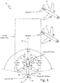
- FIG. 1 is a schematic view of an exemplary aircraft collision alerting system used by a taxiing aircraft.
- aircraft taxi scenario 10 includes taxiing aircraft 12 and two parked aircraft 14, 16.
- Taxiing aircraft 12 has cabin 18, left wing 20, right wing 22 and tail 24.
- Tail 24 has vertical stabilizer 26.
- Left engine 28 hangs from left wing 20, and right engine 30 hangs from right wing 22.
- Taxiing aircraft 12 is equipped with one embodiment of aircraft collision alerting system 32.
- Aircraft collision alerting system 32 includes light projector 34, left-side camera 36, and right-side camera 38. In the depicted embodiment, light projector 34 is mounted on vertical stabilizer 26 of tail 24.
- Light projector 34 is configured to project pulses of spatially-patterned light onto a scene external to taxiing aircraft 12, thereby providing rapidly-changing illumination of a spatially-patterned portion of the scene.
- the scene may include objects nearby and external to taxiing aircraft 12.
- Light projector 34 can be mounted at other locations on taxiing aircraft 12 in other embodiments..
- Light projector 34 projects the pulses of spatially-patterned light over a solid angle of illumination.
- the projected pulses of spatially-patterned light illuminate objects that reside within the solid angle of illumination.
- light projector 34 has an optical axis that is coplanar with cabin axis 40 of taxiing aircraft 12.
- Light projector 34 is shown illuminating objects that are within an azimuthal range of +/- 85 degrees, for example, of cabin axis 40 of taxiing aircraft 12, and within an elevation range of a projection horizon of light projector 34.
- the elevation range of projection for example, can be from about +3, +5, +10, +12, or +15 degrees to about -2, -5, -8, or -10 degrees of projection from a vertical location of light projector 34, sufficient to encompass the wingtips of left wing 20 and right wing 22, as well as a plane extending forward of these wingtips parallel to cabin axis 40.
- the projected pulses of spatially-patterned light can intermittently illuminate objects within the solid angle of illumination.
- illumination may use light of various wavelengths.
- infrared light being invisible to humans, can be used to provide illumination of objects within the solid angle of illumination.
- Infrared light can advantageously be non-distractive to pilots and to other people upon whom the pulses of spatially-patterned light is projected.
- a temporal change in the intensity of the illuminating pulses is controllable. Such temporal changes in the intensity of illuminating pulses can be controlled, for example, by controlling a rise time and/or a peak power of the illuminating pulses.
- the spatially-patterned light is pulsed for a limited time, with image capture synchronized with the projector illumination.
- left-side camera 36 and right-side camera 38 are synchronized with light projector 34.
- Left-side camera 36 and right-side camera 38 are configured with a pulse mode in which pulse images, which are indicative of a measure of a rate of change of light incident on a focal plane array, are generated.
- pulse images can be binary images, in which pixels indicate a binary condition.
- One exemplary binary condition may be whether the rate of change of light intensity incident upon each pixel is greater than a predetermined threshold.
- the threshold used in comparison with the temporal change in light intensity is controllable.
- Such pulse-mode operation can advantageously permit low-power pulsing of the spatially-patterned light. Because the pulse images are indicative of changes in light intensity, a pulse can be very short in duration and still provide rapidly-changing illumination.
- the synchronized exposure timings of the pulse images can be correspondingly short in duration.
- the synchronized exposures timings should include at least a rapidly-changing beam-intensity portion of each of the projected pulses. Such short duration exposures reduce the amount of light from sources other than light projector 34 from being received and focused on the focal plane array.
- left-side camera 36 and right-side camera 38 are also configured with a normal mode in which standard-contrast images are generated.
- Standard-contrast images are indicative of a measure of integrated light intensity over an exposure time.
- Each pixel of a focal plane array may generate a word of data indicative of the light intensity integrated over the exposure time.
- the word depth can be eight, sixteen, twenty-four, or thirty-two bits, or other numbers of bits. The larger word depths are capable of providing data indicative of finer resolutions than the smaller word depths.
- the standard-contrast images can be used in conjunction with the pulse images as will be explained below.
- light having wavelengths within an atmospheric absorption band can be used. Careful selection of projector wavelength can permit light projector 34 to compete less with the solar energy. There are, however, certain wavelengths where the atmospheric absorption is so great that both projector energy and solar energy are attenuated equally.
- Light is broadband as emitted from the sun with a maximum intensity falling in the visible light spectrum. Sunlight having wavelengths within the infrared spectrum is of lower intensity than the visible band. And so, projected light having such wavelengths need not compete with the sunlight. Using light having such wavelengths can thereby permit reduced power levels in projecting pulses of spatially-patterned light. Atmospheric absorption bands may further reduce solar infrared illumination.
- atmospheric absorption bands include infrared wavelengths of between about 1.35-1.4, 1.8-1.95, 2.5-2.9, and 5.5-7.2 microns.
- the pulses of spatially-patterned light that are projected by light projector 34 can be identified in images formed by cameras 36, 38. Using knowledge of the location from which the pulses were projected (e.g., the location of image projector 34), the location of the cameras 36, 38 and the location within the pulse images (e.g., pixel coordinates) where the feature is imaged can permit location determination using triangulation. For example, light projector 34 can be located at an elevation on taxiing aircraft 12 that is higher than an elevation where cameras 36, 38 are located. A location of the imaged feature can be used to determine trajectory and/or range data (e.g., distance) to the object(s) from which that specific feature is reflected.
- trajectory and/or range data e.g., distance
- Light projector 34 can emit a structured beam of light to produce a pattern that, when reflected from a screen having a normal direction to cabin axis 40, is imaged as horizontal lines by cameras 36 and 38.
- One structured beam might be projected at an angle of elevation of zero degrees (i.e., directed parallel to the horizon).
- a second structured beam might be projected at an angle of negative five degrees from the horizon (i.e., directed at a slightly downward angle from light projector 34).
- Each of these projected structured beams of light when reflected from an object, will be imaged at a different vertical location (e.g., each will have a different vertical pixel coordinate) within the camera image, depending on the range distance between the reflecting object and taxiing aircraft 12.
- Knowing the elevation of light projector 34, the elevations of cameras 36, 38, the specific feature of the projected pulses of spatially-patterned light (e.g., which horizontal line is imaged), and the location within the camera image where the specific feature is imaged can permit a determination of the range of the object from which the specific feature has been reflected.
- pilots taxiing aircraft 12 can be informed of any potential collision hazards within the scene illuminated by light projector 34. Pilots of taxiing aircraft 12 can steer aircraft 12 to avoid wingtip collisions and/or engine collisions based on the trajectory and/or range information that is calculated by aircraft collision alerting system 32.
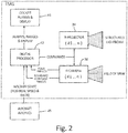
- FIG. 2 is a block diagram of an exemplary aircraft collision alerting system.
- Aircraft collision alerting system 32 includes infrared light projector(s) 34, camera(s) 36, image processor 42, and cockpit alarm and display module 44.
- Infrared light projector(s) 34 is configured to be mounted at a projector location on an aircraft.
- Infrared light projector(s) 34 is further configured to project spatially-patterned light from infrared light projector(s) 34 onto a scene external to the aircraft, thereby illuminating a spatially-patterned portion of the scene.
- Camera(s) 36 is configured to be mounted at one or more camera locations on the aircraft. Camera(s) 36 is further configured to receive light reflected from the scene. Camera(s) 36 is further configured to focus the received light onto a focal plane array comprising a plurality of light-sensitive pixels, thereby forming an image of the scene.
- the image can include pixel data generated by the plurality of light-sensitive pixels.
- camera(s) 36 generates a pulse image and a standard-contrast image.
- Digital processor 42 receives inputs from camera(s) 36 and from aircraft avionics 45. Digital processor 42 generates commands that control the operation of infrared light projector(s) 34 and camera(s) 36. Digital processor 42 outputs alarms, calculate ranges of object(s), and images to cockpit alarms and display module 44. Digital processor 42 is configured to identify pixel coordinates corresponding to a subset of the plurality of light-sensitive pixels upon which the spatially-patterned light projected by infrared light projector(s) 34 and reflected from the spatially-patterned portion of the scene is focused.
- Digital processor 42 is further configured to use triangulation, based on the projector location of infrared light projector(s) 34, the location(s) of camera(s) 36 and the identified pixel coordinates corresponding to pixels receiving rapidly-changing light intensities, to calculate range value data of object(s) in the scene from which the spatially-patterned light projected by infrared light projector(s) 34 is reflected.
- FIG. 3 is a detailed block diagram of the exemplary aircraft collision alerting system depicted in FIG. 2 .
- Aircraft collision alerting system 32 includes infrared light projector(s) 34, camera(s) 36, image processor 42, and cockpit alarm and display module 44.
- Infrared light projector(s) 34 is configured to be mounted at a projector location on an aircraft.
- Infrared light projector(s) 34 is further configured to project pulses of spatially-patterned light from infrared light projector(s) 34 onto a scene external to the aircraft, thereby providing rapidly-changing illumination of a spatially-patterned portion of the scene.
- Image processor 42 is shown in greater detail than shown in FIG. 2 .
- Image processor 42 includes imaging control logic 46, detector 48, object boundary modeler 50, zone checker 52 and Simultaneous Localization And Mapping (SLAM) and Detection And Tracking of Moving Objects (DATMO) module 54.
- Imaging control logic 46 can generate commands that control operation of infrared light projector(s) 34 and camera(s) 36. For example, imaging control logic 46 can control a timing of when infrared light projector(s) 34 generates pulses of spatially-patterned light and projects the pulses of spatially-patterned light upon a scene external to the aircraft.
- Imaging control logic 46 can be configured to control a peak intensity of the pulses and a rise time for the pulses, the rise time being the time interval in which the intensity of the pulse changes from zero power to peak power.
- Imaging control logic 46 can be configured to direct infrared light projector(s) 34 to emit different pulse intensities and pulse rise times into different areas of the spatial pattern. Imaging control logic 46 can adjust the intensities of the projected pulses so as to compensate, for example, for distances to objects, surface angles of objects, and/or reflectivities of objects. Imaging control logic 46 can control a timing of when camera(s) 36 generates images of the scene (e.g., pulse images and/or standard-contrast images). Such timing coordination can be used to ensure that images generated by camera(s) 36 contain and/or exclude the pulses of spatially-patterned light projected from infrared light projector(s) 34, for example.
- Detector 48 is configured to receive the pulse images generated by camera(s) 36. Detector 48 is further configured to identify locations within the received pulse images that include light of the projected pulses of spatially-patterned light reflected from an object in the scene. Detector 48 is further configured to identify the specific features of the pulses of spatially-patterned light corresponding to the identified locations. For example, detector 48 may identify a first subset of the plurality of pixels of the image as being associated with a first horizontal line, and a second subset of the plurality of pixels with a second horizontal line.
- Detector 48 can use pulse image pairs in identifying locations within the received images that include light of the projected pulses of spatially-patterned light reflected from an object in the scene. For example, a first image of the received image pair can be generated by camera(s) 36 at a time when infrared light projector(s) 34 is providing pulsed illumination of the scene. A second image of the received image pair can be generated by camera(s) 36 at a time when infrared light projector(s) 34 is not providing pulsed illumination of the scene. These first images of the received image pairs thereby contain light projected by infrared light projector(s) 34 and reflected from the objects in the scene.
- the second images of the received image pairs do not contain light projected by infrared light projector(s) 34 and reflected from the objects in the scene, but only light reflected from the objects that is projected thereon from other sources or light emitted from various sources in the scene.
- Detector 48 can generate a difference image based on a difference between the first and second images of each image pair. This technique can at least partially reduce the pixel response of light produced by sources other than infrared light projector(s) 34. In some embodiments, negative values generated by taking the difference between the first and second images of these image pairs are set to zero.
- each feature is encoded by modulating the intensity of that feature in the time domain and/or in the spatial domain.
- each horizontal line can be encoded in the time domain using pulse rise-time modulation and/or pulse peak modulation.
- each horizontal line can be encoded differently in the spatial domain as different dashed patterns, for example.
- each feature may be illuminated at a different time. Multiple images can be generated by the camera, so as to sequentially capture each of the separately timed features.
- different frequencies of light can be used for different features.
- Object boundary modeler 50 receives the pulse locations identified by detector 50. Object boundary modeler 50 also receives the passive images (e.g., those images that do not contain light projected by infrared light projector(s) 34) from camera(s) 36. Object boundary modeler 50 determines pixel boundaries of various objects imaged in passive images received by camera(s) 36. Object boundary modeler 50 may use local groupings of the received pulse locations and the corresponding calculated ranges corresponding to these pulse locations to identify separate structures or a continuum of a single structure. For example, local groupings of identified pulse locations that have similar corresponding locations might be associated with a common object. The passive image can be processed using various boundary and/or edge detection algorithms to identify potential object boundaries.
- Local groupings having similar corresponding calculated ranges can be used to annotate objects with identified boundary edges.
- the passive images with identified boundary edges can be used to show the spatial extent of the ranged objects.
- Object boundary modeler can be used to interpolate the range of every pixel within the identified boundary edges using the nearby members of the grouping of calculated ranges.
- Zone checker 52 receives the identified boundaries of ranged objects from object boundary modeler 50. Zone checker 52 then compares the trajectory and/or range of such objects with the taxi path of taxiing airplane 12 and determines a collision risk score. If, for example, the collision risk score exceeds a predetermined value, then zone checker 52 may generate an alert signal and output it to cockpit alarms and display module 44. Zone checker 52 may also output passive images annotated with range values corresponding to detected objects for visual display on a display screen of cockpit alarms and display module 44.
- Zone checker 52 can use a zone or multiple zones in determining a risk score.
- a zone for example, can be a keep-out box surrounding the aircraft or some portion of the aircraft. Any object detected to be within the keep-out zone can cause zone checker 52 to generate an alert signal.
- a series of zones around key aircraft components may be used, such as, for example, around wing-tips and/or engines. These zones can extend above and/or below the occupied region of these aircraft components to include a safety margin in elevation. These zones can also extend forward/aft or inboard/outboard of the aircraft components to provide safety margin in the direction of a plane trajectory.
- a volume of an audible alert signal can be adapted to the closing speed and/or range of the objects which are on a collision course with taxiing aircraft 12. For example, a risk score may be increased for an object in a forward zone as the speed of taxiing aircraft 12 increases. In some embodiments, a lateral danger zone for objects located laterally from the wingtips of taxiing aircraft 12 can be reduced as taxiing aircraft 12 slows down to permit the pilot to crawl past objects in tight quarters.
- SLAM-DATMO module 54 is configured to track the detected and ranged objects. SLAM-DATMO module 54 receives the object boundaries detected by object boundary modeler 50 and receives the location values of such objects as inputs. In some embodiments, SLAM-DATMO module 54 also receives the passive images generated by camera(s) 36. SLAM-DATMO module 54 includes object association module 56, object mapping module 58, and predictor module 60. Object association module 56 associates detected objects in a current frame of a passive image with corresponding detected objects in a previous frame of a passive image.
- SLAM-DATMO module 54 can track a lateral movement (e.g., in the x and y pixel coordinate directions) and the range movement (e.g., toward or away from taxiing aircraft 12) of the detected objects.
- SLAM-DATMO module 54 can determine if the detected objects are stationary or moving. This information, in conjunction with outputs from object body modeler 50, can enhance ability to characterize object type.
- Predictor 60 can then use this information along with the past and current movements of the detected objects to predict future ranges and movements of these detected objects. Predictor 60 can then output these future predictions to zone checker 52 for use in identifying a collision risk score. In some embodiments, predictor 60 can predict a time to impact of the aircraft and the detected objects.
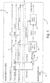
- FIG. 4 is a timing diagram depicting the timing of various operations of the exemplary aircraft collision alerting system depicted in FIGS. 2-3 .
- timing diagram 62 has horizontal axis 64. Horizontal axis 64 corresponds to time.
- Timing diagram 62 includes light projector timing signal 66, pulse image exposure timing signal 68, and standard-contrast image exposure timing signal 70.
- Light projector timing signal 66 controls the projection of pulses of spatially-patterned light by infrared light projector(s) 34.
- Pulse image exposure timing signal 68 controls the timing of pulse image generation by camera(s) 36.
- Standard-contrast image exposure timing signal 68 controls the timing of standard-contrast image generation by camera(s) 36.
- Each of the control signals 66, 68 and 70 are depicted for two periodic cycles in timing diagram 62.
- Each periodic cycle of timing diagram 62 depicts camera exposure timing signals that command camera(s) 36 to obtain three different images per periodic cycle.
- Camera(s) 36 is commanded to generate a first pulse image during a time span in which projector timing signal 66 commands infrared light projector(s) 34 to project pulses of spatially-patterned light upon the scene.
- Camera(s) 36 is commanded to generate a second pulse image during a time span in which projector timing signal 66 commands infrared light projector(s) 34 to be in an off state.
- Camera(s) 36 is commanded to generate a standard-contrast image during a time span in which projector timing signal 66 commands infrared light projector(s) 34 again to be in an off state.
- Exposure timing of the standard-contrast image may be increased to improve the quality of the standard-contrast image, for example.
- FIG. 4 also depicts a simplified block diagram of a portion of aircraft collision alerting system 32 for the purpose of explaining how the three images captured by camera(s) 36 can be used to provide trajectory and/or range data to a pilot of an aircraft.
- Aircraft collision alerting system 32 includes difference image generator 74, structured-light analysis module 76 and image overlay engine 78.
- Difference image generator 74 generates an image corresponding to a difference between the first and second pulse images generated by camera(s) 36.
- Structured light analysis module 76 receives the generated difference image and calculates trajectory and/or range data based on the received difference image.
- Image overlay engine 78 receives the standard-contrast image generated by camera(s) 36 and annotates the received standard-contrast image with the calculated trajectory and/or range data received from structured light analysis module 76.
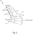
- FIG. 5 is a schematic diagram depicting object range determination using both active and passive imaging.
- camera image 80 of tail 82 of aircraft 14 external to taxiing aircraft 12 is shown.
- Camera image 80 is composed from intensity data of a two-dimensional array of light-sensitive pixels (not individually depicted).
- Tail 82 includes vertical stabilizer 84 and horizontal stabilizer 86.
- Vertical stabilizer 84 depicts features 88 of pulses of spatially-patterned light projected thereon.
- Features 88 are diagonal lines of light.
- Features 88 are imaged by a subset of the two-dimensional array of light-sensitive pixels composing the image. For each of the subset of the two-dimensional array of light-sensitive pixels containing the pulses of spatially-patterned light projected upon tail 82, a range value is calculated.
- range values can be calculated using the already calculated range values corresponding to nearby pixels.
- range values can be calculated for the pixels determined to be boundary pixels of an object.
- Range values for boundary pixels 90 may be calculated by modeling the range variations within a single object as a polynomial function of spatial coordinates, for example. Such a model may be used to calculate range values using the pixel coordinates and corresponding range values of pixels having already calculated range values that reside within the object boundary associated with boundary pixels 90.
- Various embodiments can use various configurations of spatially-patterned light having various features. For example, in some embodiments, vertical or diagonal lines can be projected upon a scene. In some embodiments, spots of light can be projected upon a scene. In an exemplary embodiment, both vertical lines and horizontal lines can be projected upon a scene, using projectors that are horizontally and/or vertically displaced, respectively, from the camera location.
- Apparatus and associated methods relate to a system for calculating trajectory and/or range data of object(s) external to an aircraft.
- the system includes a light projector configured to be mounted at a projector location on the aircraft and to project pulses of spatially-patterned light from the light projector onto a scene external to the aircraft, thereby providing rapidly-changing illumination of a spatially-patterned portion of the scene.
- the system includes a camera configured to be mounted at a camera location on the aircraft and to receive a portion of the projected pulses of spatially-patterned light reflected by the scene. The camera is further configured to focus the received portion onto a focal plane array comprising a plurality of light-sensitive pixels.
- the camera has a pulse-mode in which the camera forms a pulse image comprising pixel data generated by the plurality of light-sensitive pixels.
- the pixel data is indicative of a rate of change of light intensity focused thereon exceeding a predetermined threshold.
- the system also includes an image processor configured to identify pixel coordinates corresponding to a subset of the plurality of light-sensitive pixels indicative of the rate change of light intensity focused thereon exceeding a predetermined threshold.
- the image processor is further configured to calculate, based on the projector location of the light projector, the camera location of the camera and the identified pixel coordinates, trajectory and/or range data of object(s) in the scene from which the spatially-patterned light projected by the light projector is reflected.
- the system of the preceding paragraph can optionally include, additionally and/or alternatively, any one or more of the following features, configurations and/or additional components:
- a further embodiment of the foregoing system wherein the camera is configured to form a first pulse image while the light projector is projecting a pulse of spatially-patterned light onto the scene.
- a further embodiment of any of the foregoing systems wherein the camera is configured to form a second pulse image while the light projector is not projecting a pulse of spatially-patterned light onto the scene.
- the image processor is configured to generate a difference image based on a difference of the first and second pulse images.
- the image processor is configured to control a rise time and/or a peak power of the projected pulses of spatially-patterned light.
- the image processor is configured to generate a standard-contrast image while the light projector is not projecting a pulse of spatially patterned light onto the scene.
- spatially-patterned light comprises a series of spatially-separated lines or points of light.
- the spatially-patterned light projected by the light projector comprises infrared light and the camera is an infrared camera and each of the plurality of light-sensitive pixels is sensitive to infrared light.
- the spatially-patterned light projected by the light projector comprises infrared light having a wavelength corresponding to a lower solar intensity portion or to an atmospheric absorption band.
- a further embodiment of any of the foregoing systems further including a cockpit notification system configured to generate an alert signal if the calculated trajectory and/or range data of object(s) indicate that object(s) are within a collision zone or on a collision trajectory.
- cockpit notification system includes an audible alarm that is activated when the calculated trajectory and/or range data indicates one or more of the object(s) in the scene has a combination of an object range and an object direction relative to the aircraft corresponding to a risk of collision.
- cockpit notification system includes a display device configured to display the one or more images of the scene annotated with the calculated trajectory and/or range data.
- apparatus and associated methods relate to a method for generating an alert signal of a potential aircraft collision.
- the method includes projecting pulses of spatially-patterned light from a light projector onto a scene external to an aircraft, thereby providing pulsed illumination of a spatially-patterned portion of the scene.
- the spatially-patterned portion of the scene thereby receives a rapid change in illumination.
- the method includes receiving a portion of the projected pulses of spatially-patterned light reflected by the scene.
- the method includes focusing, by a camera, the received portion onto a focal plane array comprising a plurality of light-sensitive pixels.
- the method includes forming, by the camera, a pulse image indicative of a change of reflected light intensity exceeding a predetermined threshold.
- the pulse image includes pixel data generated by the plurality of light-sensitive pixels.
- the method includes identifying pixel coordinates corresponding to a subset of the plurality of light-sensitive pixels that are indicative of the rapid change of light intensity exceeding a predetermined threshold.
- the method includes calculating, based on a projector location of the light projector, a camera location of the camera and the identified pixel coordinates, trajectory and/or range data of object(s) in the scene from which the spatially-patterned light projected by the light projector is reflected.
- the method also includes outputting an alert signal if the calculated trajectory and/or range data of object(s) indicates one or more of the object(s) in the scene has a combination of a range and/or a trajectory relative to the aircraft corresponding to a risk of collision.
- the method of the preceding paragraph can optionally include, additionally and/or alternatively, any one or more of the following features, configurations and/or additional components:
- the pulse image is a first pulse image.
- the method further includes forming, by the camera, a second pulse image indicative of a rapid change of reflected light intensity.
- the pulse image includes pixel data generated by the plurality of light-sensitive pixels.
- the first pulse image is formed when one of pulses of spatially-patterned light is projected onto the scene and the second pulse image is formed when none of the pulses of spatially-patterned light is projected onto the scene.
- a further embodiment of any of the foregoing methods further including generating a difference image based on a difference of the first and second pulse images.
- a further embodiment of any of the foregoing methods further including controlling a rise time and/or a peak power of the projected pulses of spatially-patterned light.
- a further embodiment of any of the foregoing methods further including activating an audible alarm in response to outputting the alert signal.
- a further embodiment of any of the foregoing methods further including forming, by the camera, a standard-contrast image indicative of integrated light intensity over an exposure time.
- a further embodiment of any of the foregoing methods further including displaying the standard-contrast image of the scene annotated with the calculated trajectory and/or range data.
Landscapes
- Engineering & Computer Science (AREA)
- Physics & Mathematics (AREA)
- General Physics & Mathematics (AREA)
- Multimedia (AREA)
- Theoretical Computer Science (AREA)
- Aviation & Aerospace Engineering (AREA)
- Computer Vision & Pattern Recognition (AREA)
- Signal Processing (AREA)
- Mechanical Engineering (AREA)
- Optics & Photonics (AREA)
- Artificial Intelligence (AREA)
- Measurement Of Optical Distance (AREA)
- Optical Radar Systems And Details Thereof (AREA)
- Traffic Control Systems (AREA)
Abstract
Description
- Each year, significant time and money are lost due to commercial aircraft accidents and incidents during ground operations, of which significant portions occur during taxiing maneuvers. During ground operations, aircraft share the taxiways with other aircraft, fuel vehicles, baggage carrying trains, mobile stairways and many other objects. Aircrafts often taxi to and/or from fixed buildings and other fixed objects. Should an aircraft collide with any of these objects, the aircraft must be repaired and recertified as capable of operation. The cost of repair and recertification, as well as the lost opportunity costs associated with the aircraft being unavailable for use can be very expensive.
- Pilots are located in a central cockpit where they are well positioned to observe objects that are directly in front of the cabin of the aircraft. Wings extend laterally from the cabin in both directions. Some commercial and some military aircraft have large wingspans, and so the wings on these aircraft laterally extend a great distance from the cabin and are thus positioned behind and out of the field of view of the cabin. Some commercial and some military planes have engines that hang below the wings of the aircraft. Pilots, positioned in the cabin, can have difficulty knowing the risk of collisions bet ween the wingtips and/or engines and other objects external to the aircraft. An aircraft on-ground collision alerting system would be useful to survey the area forward or aft of the tail, wingtips and/or engines, to detect obstructions in a potential collision path, and to provide visual and audible alerts to the cockpit.
- Apparatus and associated methods relate to a system for calculating trajectory and/or range data of object(s) external to an aircraft. The system includes a light projector configured to be mounted at a projector location on the aircraft and to project pulses of spatially-patterned light from the light projector onto a scene external to the aircraft, thereby providing rapidly-changing illumination of a spatially-patterned portion of the scene. The system includes a camera configured to be mounted at a camera location on the aircraft and to receive a portion of the projected pulses of spatially-patterned light reflected by the scene. The camera is further configured to focus the received portion onto a focal plane array comprising a plurality of light-sensitive pixels. The camera has a pulse-mode in which the camera forms a pulse image comprising pixel data generated by the plurality of light-sensitive pixels. The pixel data is indicative of a rate of change of light intensity focused thereon exceeding a predetermined threshold. The system also includes an image processor configured to identify pixel coordinates corresponding to a subset of the plurality of light-sensitive pixels indicative of the rate change of light intensity focused thereon exceeding a predetermined threshold. The image processor is further configured to calculate, based on the projector locations of the light projector, the camera location of the camera and the identified pixel coordinates, trajectory and/or range data of object(s) in the scene from which the spatially-patterned light projected by the light projector is reflected.
- Some embodiments relate to a method for generating an alert signal of a potential aircraft collision. The method includes projecting pulses of spatially-patterned light from the light projector onto a scene external to an aircraft, thereby providing pulsed illumination of a spatially-patterned portion of the scene. The spatially-patterned portion of the scene thereby receives a rapid change in illumination. The method includes receiving a portion of the projected pulses of spatially-pattern light reflected by the scene. The method includes focusing the received portion onto a focal plane array comprising a plurality of light-sensitive pixels. The method includes forming a pulse image indicative of a change of light intensity exceeding a predetermined threshold. The pulse image includes pixel data generated by the plurality of light-sensitive pixels. The method includes identifying pixel coordinates corresponding to a subset of the plurality of light-sensitive pixels that are indicative of the rapid change of light intensity exceeding a predetermined threshold. The method also includes calculating, based on the projector locations of the light projector, the camera location of the camera and the identified pixel coordinates, trajectory and/or range data of object(s) in the scene from which the spatially-patterned light projected by the light projector is reflected.
-
-
FIG. 1 is a schematic view of an exemplary aircraft collision alerting system used by an aircraft during on-ground operations. -
FIG. 2 is a block diagram of an exemplary aircraft collision alerting system. -
FIG. 3 is a detailed block diagram of the exemplary aircraft collision alerting system depicted inFIG. 2 . -
FIG. 4 is a timing diagram depicting the timing of various operations of the exemplary aircraft collision alerting system depicted inFIGS. 2-3 . -
FIG. 5 is a schematic diagram depicting object range determination using both active and passive imaging. - Apparatus and associated methods relate to ranging object(s) nearby an aircraft using triangulation of pulses of spatially-patterned light projected upon and reflected by the object(s). The projected pulses provide rapidly-changing illumination of a spatially patterned portion of the scene. A camera receives a reflected portion of the projected pulse and focuses the received portion onto a plurality of light-sensitive pixels, thereby forming a pulse image. The pulse image includes pixel data indicative of a rate of change of light intensity focused thereon exceeding a predetermined threshold. Pixel coordinates, corresponding to a subset of the plurality of light-sensitive pixels that are indicative of the rate of change of light intensity exceeding a predetermined threshold, are identified. Trajectory and/or range data of object(s) in the scene are calculated, based on a projector location, a camera location, and the identified pixel coordinates.
- In some embodiments, pulse images of the object are captured both with and without pulsed illumination by the spatially-patterned light. A difference between these two pulse images can be used to help isolate the reflections of the spatially-patterned light, by removing persistent sources of rapidly-changing light (e.g., a flashing beacon). In some embodiments, the camera is further configured to generate standard-contrast images in which light is integrated over an exposure time. Standard-contrast images can be used in conjunction with the pulse images. For example, standard images may be presented to a pilot annotated by range data captured by the pulse images. Standard images can be used in conjunction with the pulse images to identify pixel boundaries of the object and to calculate range values of portions of the object corresponding to pixels imaging the spatially-patterned light projected onto the scene. For pixels imaging reflections of the spatially-patterned light, triangulation can be used to calculate range. For pixels not imaging reflections of the spatially-patterned light, range can be calculated using one or more calculated ranges corresponding to nearby pixels imaging the spatially-patterned light reflected from the object. Using these two ranging techniques provides pixel level resolution of trajectory and/or range data, while requiring only sparse illumination of objects by spatially-patterned light.
-
FIG. 1 is a schematic view of an exemplary aircraft collision alerting system used by a taxiing aircraft. InFIG. 1 ,aircraft taxi scenario 10 includes taxiingaircraft 12 and two parkedaircraft Taxiing aircraft 12 hascabin 18,left wing 20,right wing 22 andtail 24.Tail 24 hasvertical stabilizer 26.Left engine 28 hangs fromleft wing 20, andright engine 30 hangs fromright wing 22.Taxiing aircraft 12 is equipped with one embodiment of aircraftcollision alerting system 32. Aircraftcollision alerting system 32 includeslight projector 34, left-side camera 36, and right-side camera 38. In the depicted embodiment,light projector 34 is mounted onvertical stabilizer 26 oftail 24.Light projector 34 is configured to project pulses of spatially-patterned light onto a scene external to taxiingaircraft 12, thereby providing rapidly-changing illumination of a spatially-patterned portion of the scene. The scene may include objects nearby and external to taxiingaircraft 12.Light projector 34 can be mounted at other locations on taxiingaircraft 12 in other embodiments.. -
Light projector 34 projects the pulses of spatially-patterned light over a solid angle of illumination. The projected pulses of spatially-patterned light illuminate objects that reside within the solid angle of illumination. In the depicted embodiment,light projector 34 has an optical axis that is coplanar withcabin axis 40 of taxiingaircraft 12.Light projector 34 is shown illuminating objects that are within an azimuthal range of +/- 85 degrees, for example, ofcabin axis 40 of taxiingaircraft 12, and within an elevation range of a projection horizon oflight projector 34. The elevation range of projection, for example, can be from about +3, +5, +10, +12, or +15 degrees to about -2, -5, -8, or -10 degrees of projection from a vertical location oflight projector 34, sufficient to encompass the wingtips ofleft wing 20 andright wing 22, as well as a plane extending forward of these wingtips parallel tocabin axis 40. - In some embodiments, the projected pulses of spatially-patterned light can intermittently illuminate objects within the solid angle of illumination. Such illumination may use light of various wavelengths. For example, in some embodiments, infrared light, being invisible to humans, can be used to provide illumination of objects within the solid angle of illumination. Infrared light can advantageously be non-distractive to pilots and to other people upon whom the pulses of spatially-patterned light is projected. In some embodiments, a temporal change in the intensity of the illuminating pulses is controllable. Such temporal changes in the intensity of illuminating pulses can be controlled, for example, by controlling a rise time and/or a peak power of the illuminating pulses.
- In some embodiments, the spatially-patterned light is pulsed for a limited time, with image capture synchronized with the projector illumination. In some embodiments, left-
side camera 36 and right-side camera 38 are synchronized withlight projector 34. Left-side camera 36 and right-side camera 38 are configured with a pulse mode in which pulse images, which are indicative of a measure of a rate of change of light incident on a focal plane array, are generated. In some embodiments, such pulse images can be binary images, in which pixels indicate a binary condition. One exemplary binary condition may be whether the rate of change of light intensity incident upon each pixel is greater than a predetermined threshold. Pixels upon which the incident light intensity changes at a rate greater than the predetermined threshold may indicate such a condition by producing a signal of a first state. Pixels upon which the incident light intensity changes at a rate not greater than the predetermined threshold may indicate such a condition by producing a signal of a second state. In some embodiments, the threshold used in comparison with the temporal change in light intensity is controllable. - Such pulse-mode operation can advantageously permit low-power pulsing of the spatially-patterned light. Because the pulse images are indicative of changes in light intensity, a pulse can be very short in duration and still provide rapidly-changing illumination. The synchronized exposure timings of the pulse images can be correspondingly short in duration. The synchronized exposures timings should include at least a rapidly-changing beam-intensity portion of each of the projected pulses. Such short duration exposures reduce the amount of light from sources other than
light projector 34 from being received and focused on the focal plane array. - In some embodiments, left-
side camera 36 and right-side camera 38 are also configured with a normal mode in which standard-contrast images are generated. Standard-contrast images are indicative of a measure of integrated light intensity over an exposure time. Each pixel of a focal plane array may generate a word of data indicative of the light intensity integrated over the exposure time. In some embodiments, the word depth can be eight, sixteen, twenty-four, or thirty-two bits, or other numbers of bits. The larger word depths are capable of providing data indicative of finer resolutions than the smaller word depths. The standard-contrast images can be used in conjunction with the pulse images as will be explained below. - In some embodiments, light having wavelengths within an atmospheric absorption band can be used. Careful selection of projector wavelength can permit
light projector 34 to compete less with the solar energy. There are, however, certain wavelengths where the atmospheric absorption is so great that both projector energy and solar energy are attenuated equally. Light is broadband as emitted from the sun with a maximum intensity falling in the visible light spectrum. Sunlight having wavelengths within the infrared spectrum is of lower intensity than the visible band. And so, projected light having such wavelengths need not compete with the sunlight. Using light having such wavelengths can thereby permit reduced power levels in projecting pulses of spatially-patterned light. Atmospheric absorption bands may further reduce solar infrared illumination. For example, atmospheric absorption bands include infrared wavelengths of between about 1.35-1.4, 1.8-1.95, 2.5-2.9, and 5.5-7.2 microns. - The pulses of spatially-patterned light that are projected by
light projector 34 can be identified in images formed bycameras cameras light projector 34 can be located at an elevation on taxiingaircraft 12 that is higher than an elevation wherecameras -
Light projector 34, for example, can emit a structured beam of light to produce a pattern that, when reflected from a screen having a normal direction tocabin axis 40, is imaged as horizontal lines bycameras aircraft 12. Knowing the elevation oflight projector 34, the elevations ofcameras - Using the calculated range information,
pilots taxiing aircraft 12 can be informed of any potential collision hazards within the scene illuminated bylight projector 34. Pilots of taxiingaircraft 12 can steeraircraft 12 to avoid wingtip collisions and/or engine collisions based on the trajectory and/or range information that is calculated by aircraftcollision alerting system 32. -
FIG. 2 is a block diagram of an exemplary aircraft collision alerting system. Aircraftcollision alerting system 32 includes infrared light projector(s) 34, camera(s) 36,image processor 42, and cockpit alarm anddisplay module 44. Infrared light projector(s) 34 is configured to be mounted at a projector location on an aircraft. Infrared light projector(s) 34 is further configured to project spatially-patterned light from infrared light projector(s) 34 onto a scene external to the aircraft, thereby illuminating a spatially-patterned portion of the scene. - Camera(s) 36 is configured to be mounted at one or more camera locations on the aircraft. Camera(s) 36 is further configured to receive light reflected from the scene. Camera(s) 36 is further configured to focus the received light onto a focal plane array comprising a plurality of light-sensitive pixels, thereby forming an image of the scene. The image can include pixel data generated by the plurality of light-sensitive pixels. In the depicted embodiment camera(s) 36 generates a pulse image and a standard-contrast image.
-
Digital processor 42 receives inputs from camera(s) 36 and fromaircraft avionics 45.Digital processor 42 generates commands that control the operation of infrared light projector(s) 34 and camera(s) 36.Digital processor 42 outputs alarms, calculate ranges of object(s), and images to cockpit alarms anddisplay module 44.Digital processor 42 is configured to identify pixel coordinates corresponding to a subset of the plurality of light-sensitive pixels upon which the spatially-patterned light projected by infrared light projector(s) 34 and reflected from the spatially-patterned portion of the scene is focused.Digital processor 42 is further configured to use triangulation, based on the projector location of infrared light projector(s) 34, the location(s) of camera(s) 36 and the identified pixel coordinates corresponding to pixels receiving rapidly-changing light intensities, to calculate range value data of object(s) in the scene from which the spatially-patterned light projected by infrared light projector(s) 34 is reflected. -
FIG. 3 is a detailed block diagram of the exemplary aircraft collision alerting system depicted inFIG. 2 . Aircraftcollision alerting system 32 includes infrared light projector(s) 34, camera(s) 36,image processor 42, and cockpit alarm anddisplay module 44. Infrared light projector(s) 34 is configured to be mounted at a projector location on an aircraft. Infrared light projector(s) 34 is further configured to project pulses of spatially-patterned light from infrared light projector(s) 34 onto a scene external to the aircraft, thereby providing rapidly-changing illumination of a spatially-patterned portion of the scene.Image processor 42 is shown in greater detail than shown inFIG. 2 . -
Image processor 42 includesimaging control logic 46,detector 48,object boundary modeler 50,zone checker 52 and Simultaneous Localization And Mapping (SLAM) and Detection And Tracking of Moving Objects (DATMO)module 54.Imaging control logic 46 can generate commands that control operation of infrared light projector(s) 34 and camera(s) 36. For example,imaging control logic 46 can control a timing of when infrared light projector(s) 34 generates pulses of spatially-patterned light and projects the pulses of spatially-patterned light upon a scene external to the aircraft.Imaging control logic 46 can be configured to control a peak intensity of the pulses and a rise time for the pulses, the rise time being the time interval in which the intensity of the pulse changes from zero power to peak power.Imaging control logic 46 can be configured to direct infrared light projector(s) 34 to emit different pulse intensities and pulse rise times into different areas of the spatial pattern.Imaging control logic 46 can adjust the intensities of the projected pulses so as to compensate, for example, for distances to objects, surface angles of objects, and/or reflectivities of objects.Imaging control logic 46 can control a timing of when camera(s) 36 generates images of the scene (e.g., pulse images and/or standard-contrast images). Such timing coordination can be used to ensure that images generated by camera(s) 36 contain and/or exclude the pulses of spatially-patterned light projected from infrared light projector(s) 34, for example. -
Detector 48 is configured to receive the pulse images generated by camera(s) 36.Detector 48 is further configured to identify locations within the received pulse images that include light of the projected pulses of spatially-patterned light reflected from an object in the scene.Detector 48 is further configured to identify the specific features of the pulses of spatially-patterned light corresponding to the identified locations. For example,detector 48 may identify a first subset of the plurality of pixels of the image as being associated with a first horizontal line, and a second subset of the plurality of pixels with a second horizontal line. -
Detector 48 can use pulse image pairs in identifying locations within the received images that include light of the projected pulses of spatially-patterned light reflected from an object in the scene. For example, a first image of the received image pair can be generated by camera(s) 36 at a time when infrared light projector(s) 34 is providing pulsed illumination of the scene. A second image of the received image pair can be generated by camera(s) 36 at a time when infrared light projector(s) 34 is not providing pulsed illumination of the scene. These first images of the received image pairs thereby contain light projected by infrared light projector(s) 34 and reflected from the objects in the scene. Conversely, the second images of the received image pairs do not contain light projected by infrared light projector(s) 34 and reflected from the objects in the scene, but only light reflected from the objects that is projected thereon from other sources or light emitted from various sources in the scene.Detector 48 can generate a difference image based on a difference between the first and second images of each image pair. This technique can at least partially reduce the pixel response of light produced by sources other than infrared light projector(s) 34. In some embodiments, negative values generated by taking the difference between the first and second images of these image pairs are set to zero. - Various methods for identifying the features imaged by camera(s) 36 can be used. In some embodiments, each feature is encoded by modulating the intensity of that feature in the time domain and/or in the spatial domain. For example, each horizontal line can be encoded in the time domain using pulse rise-time modulation and/or pulse peak modulation. In some embodiments, each horizontal line can be encoded differently in the spatial domain as different dashed patterns, for example. In some embodiments each feature may be illuminated at a different time. Multiple images can be generated by the camera, so as to sequentially capture each of the separately timed features. In some embodiments, different frequencies of light can be used for different features.
-
Object boundary modeler 50 receives the pulse locations identified bydetector 50.Object boundary modeler 50 also receives the passive images (e.g., those images that do not contain light projected by infrared light projector(s) 34) from camera(s) 36.Object boundary modeler 50 determines pixel boundaries of various objects imaged in passive images received by camera(s) 36.Object boundary modeler 50 may use local groupings of the received pulse locations and the corresponding calculated ranges corresponding to these pulse locations to identify separate structures or a continuum of a single structure. For example, local groupings of identified pulse locations that have similar corresponding locations might be associated with a common object. The passive image can be processed using various boundary and/or edge detection algorithms to identify potential object boundaries. Local groupings having similar corresponding calculated ranges can be used to annotate objects with identified boundary edges. The passive images with identified boundary edges can be used to show the spatial extent of the ranged objects. Object boundary modeler can be used to interpolate the range of every pixel within the identified boundary edges using the nearby members of the grouping of calculated ranges. -
Zone checker 52 receives the identified boundaries of ranged objects fromobject boundary modeler 50.Zone checker 52 then compares the trajectory and/or range of such objects with the taxi path of taxiingairplane 12 and determines a collision risk score. If, for example, the collision risk score exceeds a predetermined value, thenzone checker 52 may generate an alert signal and output it to cockpit alarms anddisplay module 44.Zone checker 52 may also output passive images annotated with range values corresponding to detected objects for visual display on a display screen of cockpit alarms anddisplay module 44. -
Zone checker 52 can use a zone or multiple zones in determining a risk score. A zone, for example, can be a keep-out box surrounding the aircraft or some portion of the aircraft. Any object detected to be within the keep-out zone can causezone checker 52 to generate an alert signal. In some embodiments, a series of zones around key aircraft components may be used, such as, for example, around wing-tips and/or engines. These zones can extend above and/or below the occupied region of these aircraft components to include a safety margin in elevation. These zones can also extend forward/aft or inboard/outboard of the aircraft components to provide safety margin in the direction of a plane trajectory. A volume of an audible alert signal can be adapted to the closing speed and/or range of the objects which are on a collision course with taxiingaircraft 12. For example, a risk score may be increased for an object in a forward zone as the speed of taxiingaircraft 12 increases. In some embodiments, a lateral danger zone for objects located laterally from the wingtips of taxiingaircraft 12 can be reduced as taxiingaircraft 12 slows down to permit the pilot to crawl past objects in tight quarters. - SLAM-
DATMO module 54 is configured to track the detected and ranged objects. SLAM-DATMO module 54 receives the object boundaries detected byobject boundary modeler 50 and receives the location values of such objects as inputs. In some embodiments, SLAM-DATMO module 54 also receives the passive images generated by camera(s) 36. SLAM-DATMO module 54 includesobject association module 56,object mapping module 58, andpredictor module 60.Object association module 56 associates detected objects in a current frame of a passive image with corresponding detected objects in a previous frame of a passive image. Using different frames of passive images, SLAM-DATMO module 54 can track a lateral movement (e.g., in the x and y pixel coordinate directions) and the range movement (e.g., toward or away from taxiing aircraft 12) of the detected objects. Using aircraft inputs, SLAM-DATMO module 54 can determine if the detected objects are stationary or moving. This information, in conjunction with outputs fromobject body modeler 50, can enhance ability to characterize object type.Predictor 60 can then use this information along with the past and current movements of the detected objects to predict future ranges and movements of these detected objects.Predictor 60 can then output these future predictions tozone checker 52 for use in identifying a collision risk score. In some embodiments,predictor 60 can predict a time to impact of the aircraft and the detected objects. -
FIG. 4 is a timing diagram depicting the timing of various operations of the exemplary aircraft collision alerting system depicted inFIGS. 2-3 . InFIG. 4 , timing diagram 62 hashorizontal axis 64.Horizontal axis 64 corresponds to time. Timing diagram 62 includes lightprojector timing signal 66, pulse imageexposure timing signal 68, and standard-contrast imageexposure timing signal 70. Lightprojector timing signal 66 controls the projection of pulses of spatially-patterned light by infrared light projector(s) 34. Pulse imageexposure timing signal 68 controls the timing of pulse image generation by camera(s) 36. Standard-contrast imageexposure timing signal 68 controls the timing of standard-contrast image generation by camera(s) 36. Each of the control signals 66, 68 and 70 are depicted for two periodic cycles in timing diagram 62. - Each periodic cycle of timing diagram 62 depicts camera exposure timing signals that command camera(s) 36 to obtain three different images per periodic cycle. Camera(s) 36 is commanded to generate a first pulse image during a time span in which
projector timing signal 66 commands infrared light projector(s) 34 to project pulses of spatially-patterned light upon the scene. Camera(s) 36 is commanded to generate a second pulse image during a time span in whichprojector timing signal 66 commands infrared light projector(s) 34 to be in an off state. Camera(s) 36 is commanded to generate a standard-contrast image during a time span in whichprojector timing signal 66 commands infrared light projector(s) 34 again to be in an off state. Exposure timing of the standard-contrast image may be increased to improve the quality of the standard-contrast image, for example. -
FIG. 4 also depicts a simplified block diagram of a portion of aircraftcollision alerting system 32 for the purpose of explaining how the three images captured by camera(s) 36 can be used to provide trajectory and/or range data to a pilot of an aircraft. Aircraftcollision alerting system 32 includesdifference image generator 74, structured-light analysis module 76 andimage overlay engine 78.Difference image generator 74 generates an image corresponding to a difference between the first and second pulse images generated by camera(s) 36. Structuredlight analysis module 76 receives the generated difference image and calculates trajectory and/or range data based on the received difference image.Image overlay engine 78 receives the standard-contrast image generated by camera(s) 36 and annotates the received standard-contrast image with the calculated trajectory and/or range data received from structuredlight analysis module 76. -
FIG. 5 is a schematic diagram depicting object range determination using both active and passive imaging. InFIG. 5 ,camera image 80 oftail 82 ofaircraft 14 external to taxiingaircraft 12 is shown.Camera image 80 is composed from intensity data of a two-dimensional array of light-sensitive pixels (not individually depicted).Tail 82 includesvertical stabilizer 84 andhorizontal stabilizer 86.Vertical stabilizer 84 depictsfeatures 88 of pulses of spatially-patterned light projected thereon.Features 88 are diagonal lines of light.Features 88 are imaged by a subset of the two-dimensional array of light-sensitive pixels composing the image. For each of the subset of the two-dimensional array of light-sensitive pixels containing the pulses of spatially-patterned light projected upontail 82, a range value is calculated. - Between the subset of pixels that have calculated range values are pixels upon which the pulses of spatially-patterned light has not been projected. For some, if not all, of these pixels, range values can be calculated using the already calculated range values corresponding to nearby pixels. For example, range values can be calculated for the pixels determined to be boundary pixels of an object. Range values for
boundary pixels 90 may be calculated by modeling the range variations within a single object as a polynomial function of spatial coordinates, for example. Such a model may be used to calculate range values using the pixel coordinates and corresponding range values of pixels having already calculated range values that reside within the object boundary associated withboundary pixels 90. - Various embodiments can use various configurations of spatially-patterned light having various features. For example, in some embodiments, vertical or diagonal lines can be projected upon a scene. In some embodiments, spots of light can be projected upon a scene. In an exemplary embodiment, both vertical lines and horizontal lines can be projected upon a scene, using projectors that are horizontally and/or vertically displaced, respectively, from the camera location.
- The following are non-exclusive descriptions of possible embodiments of the present invention.
- Apparatus and associated methods relate to a system for calculating trajectory and/or range data of object(s) external to an aircraft. The system includes a light projector configured to be mounted at a projector location on the aircraft and to project pulses of spatially-patterned light from the light projector onto a scene external to the aircraft, thereby providing rapidly-changing illumination of a spatially-patterned portion of the scene. The system includes a camera configured to be mounted at a camera location on the aircraft and to receive a portion of the projected pulses of spatially-patterned light reflected by the scene. The camera is further configured to focus the received portion onto a focal plane array comprising a plurality of light-sensitive pixels. The camera has a pulse-mode in which the camera forms a pulse image comprising pixel data generated by the plurality of light-sensitive pixels. The pixel data is indicative of a rate of change of light intensity focused thereon exceeding a predetermined threshold. The system also includes an image processor configured to identify pixel coordinates corresponding to a subset of the plurality of light-sensitive pixels indicative of the rate change of light intensity focused thereon exceeding a predetermined threshold. The image processor is further configured to calculate, based on the projector location of the light projector, the camera location of the camera and the identified pixel coordinates, trajectory and/or range data of object(s) in the scene from which the spatially-patterned light projected by the light projector is reflected.
- The system of the preceding paragraph can optionally include, additionally and/or alternatively, any one or more of the following features, configurations and/or additional components:
- A further embodiment of the foregoing system, wherein the camera is configured to form a first pulse image while the light projector is projecting a pulse of spatially-patterned light onto the scene.
- A further embodiment of any of the foregoing systems, wherein the camera is configured to form a second pulse image while the light projector is not projecting a pulse of spatially-patterned light onto the scene.
- A further embodiment of any of the foregoing systems, wherein the image processor is configured to generate a difference image based on a difference of the first and second pulse images.
- A further embodiment of any of the foregoing systems, wherein the image processor is configured to control a rise time and/or a peak power of the projected pulses of spatially-patterned light.
- A further embodiment of any of the foregoing systems, wherein the camera is further configured to form a standard-contrast image indicative of integrated light intensity over an exposure time.
- A further embodiment of any of the foregoing systems, wherein the image processor is configured to generate a standard-contrast image while the light projector is not projecting a pulse of spatially patterned light onto the scene.
- A further embodiment of any of the foregoing systems, wherein the spatially-patterned light comprises a series of spatially-separated lines or points of light.
- A further embodiment of any of the foregoing systems, wherein the spatially-patterned light projected by the light projector comprises infrared light and the camera is an infrared camera and each of the plurality of light-sensitive pixels is sensitive to infrared light.
- A further embodiment of any of the foregoing systems, wherein the spatially-patterned light projected by the light projector comprises infrared light having a wavelength corresponding to a lower solar intensity portion or to an atmospheric absorption band.
- A further embodiment of any of the foregoing systems, further including a cockpit notification system configured to generate an alert signal if the calculated trajectory and/or range data of object(s) indicate that object(s) are within a collision zone or on a collision trajectory.
- A further embodiment of any of the foregoing systems, wherein the cockpit notification system includes an audible alarm that is activated when the calculated trajectory and/or range data indicates one or more of the object(s) in the scene has a combination of an object range and an object direction relative to the aircraft corresponding to a risk of collision.
- A further embodiment of any of the foregoing systems, wherein the cockpit notification system includes a display device configured to display the one or more images of the scene annotated with the calculated trajectory and/or range data.
- In some embodiments, apparatus and associated methods relate to a method for generating an alert signal of a potential aircraft collision. The method includes projecting pulses of spatially-patterned light from a light projector onto a scene external to an aircraft, thereby providing pulsed illumination of a spatially-patterned portion of the scene. The spatially-patterned portion of the scene thereby receives a rapid change in illumination. The method includes receiving a portion of the projected pulses of spatially-patterned light reflected by the scene. The method includes focusing, by a camera, the received portion onto a focal plane array comprising a plurality of light-sensitive pixels. The method includes forming, by the camera, a pulse image indicative of a change of reflected light intensity exceeding a predetermined threshold. The pulse image includes pixel data generated by the plurality of light-sensitive pixels. The method includes identifying pixel coordinates corresponding to a subset of the plurality of light-sensitive pixels that are indicative of the rapid change of light intensity exceeding a predetermined threshold. The method includes calculating, based on a projector location of the light projector, a camera location of the camera and the identified pixel coordinates, trajectory and/or range data of object(s) in the scene from which the spatially-patterned light projected by the light projector is reflected. The method also includes outputting an alert signal if the calculated trajectory and/or range data of object(s) indicates one or more of the object(s) in the scene has a combination of a range and/or a trajectory relative to the aircraft corresponding to a risk of collision.
- The method of the preceding paragraph can optionally include, additionally and/or alternatively, any one or more of the following features, configurations and/or additional components:
- A further embodiment of the foregoing method, wherein the pulse image is a first pulse image. The method further includes forming, by the camera, a second pulse image indicative of a rapid change of reflected light intensity. The pulse image includes pixel data generated by the plurality of light-sensitive pixels. The first pulse image is formed when one of pulses of spatially-patterned light is projected onto the scene and the second pulse image is formed when none of the pulses of spatially-patterned light is projected onto the scene.
- A further embodiment of any of the foregoing methods, further including generating a difference image based on a difference of the first and second pulse images.
- A further embodiment of any of the foregoing methods, further including controlling a rise time and/or a peak power of the projected pulses of spatially-patterned light.
- A further embodiment of any of the foregoing methods, further including activating an audible alarm in response to outputting the alert signal.
- A further embodiment of any of the foregoing methods, further including forming, by the camera, a standard-contrast image indicative of integrated light intensity over an exposure time.
- A further embodiment of any of the foregoing methods, further including displaying the standard-contrast image of the scene annotated with the calculated trajectory and/or range data.
- While the invention has been described with reference to an exemplary embodiment(s), it will be understood by those skilled in the art that various changes may be made and equivalents may be substituted for elements thereof without departing from the scope of the invention. In addition, many modifications may be made to adapt a particular situation or material to the teachings of the invention without departing from the essential scope thereof. Therefore, it is intended that the invention not be limited to the particular embodiment(s) disclosed, but that the invention will include all embodiments falling within the scope of the appended claims.
Claims (15)
- A system for calculating trajectory and/or range data of object(s) external to an aircraft (12), the system comprising:a light projector /34) configured to be mounted at a projector location on the aircraft and to project pulses of spatially-patterned light from the light projector onto a scene external to the aircraft, thereby providing rapidly-changing illumination of a spatially-patterned portion of the scene;a camera (36, 38) configured to be mounted at a camera location on the aircraft and to receive a portion of the projected pulses of spatially-patterned light reflected by the scene, and further configured to focus the received portion onto a focal plane array comprising a plurality of light-sensitive pixels, the camera having a pulse-mode in which the camera forms a pulse image comprising pixel data generated by the plurality of light-sensitive pixels, the pixel data indicative of a rate of change of light intensity focused thereon exceeding a predetermined threshold; andan image processor (42) configured to identify pixel coordinates corresponding to a subset of the plurality of light-sensitive pixels indicative of the rate change of light intensity focused thereon exceeding a predetermined threshold, the image processor further configured to calculate, based on the projector location of the light projector, the camera location of the camera and the identified pixel coordinates, trajectory and/or range data of object(s) in the scene from which the spatially-patterned light projected by the light projector is reflected.
- The system of claim 1, wherein the camera (36, 38) is configured to form a first pulse image while the light projector (34) is projecting a pulse of spatially-patterned light onto the scene.
- The system of claim 2, wherein the camera (36, 38) is configured to form a second pulse image while the light projector (34) is not projecting a pulse of spatially-patterned light onto the scene.
- The system of claim 3, wherein the image processor (42) is configured to generate a difference image based on a difference of the first and second pulse images.
- The system of any preceding claim, wherein the image processor (42) is configured to control a rise time and/or a peak power of the projected pulses of spatially-patterned light.
- The system of any preceding claim, wherein the camera (36, 38) is further configured to form a standard-contrast image indicative of integrated light intensity over an exposure time.
- The system of claim 6, wherein the image processor (42) is configured to generate a standard-contrast image while the light projector (34) is not projecting a pulse of spatially patterned light onto the scene.
- The system of any preceding claim, wherein the spatially-patterned light comprises a series of spatially-separated lines or points of light.
- The system of any preceding claim, wherein the spatially-patterned light projected by the light projector comprises infrared light and the camera is an infrared camera and each of the plurality of light-sensitive pixels is sensitive to infrared light, and preferably wherein the spatially-patterned light projected by the light projector comprises infrared light having a wavelength corresponding to a lower solar intensity portion or to an atmospheric absorption band.
- The system of any preceding claim, further comprising a cockpit notification system (44) configured to generate an alert signal if the calculated trajectory and/or range data of object(s) indicate that object(s) are within a collision zone or on a collision trajectory, and preferably wherein the cockpit notification system includes an audible alarm that is activated when the calculated trajectory and/or range data indicates one or more of the object(s) in the scene has a combination of an object range and an object direction relative to the aircraft corresponding to a risk of collision, or wherein the cockpit notification system includes a display device configured to display the one or more images of the scene annotated with the calculated trajectory and/or range data.
- A method for generating an alert signal of a potential aircraft collision, the method comprising the steps of:projecting pulses of spatially-patterned light from a light projector onto a scene external to an aircraft, thereby providing pulsed illumination of a spatially-patterned portion of the scene, the spatially-patterned portion of the scene thereby receiving a rapid change in illumination;receiving a portion of the projected pulses of spatially-patterned light reflected by the scene;focusing, by a camera, the received portion onto a focal plane array comprising a plurality of light-sensitive pixels;forming, by the camera, a pulse image indicative of a change of reflected light intensity exceeding a predetermined threshold, the pulse image comprising pixel data generated by the plurality of light-sensitive pixels;identifying pixel coordinates corresponding to a subset of the plurality of light-sensitive pixels that are indicative of the rapid change of light intensity exceeding a predetermined threshold;calculating, based on a projector location of the light projector, a camera location of the camera and the identified pixel coordinates, trajectory and/or range data of object(s) in the scene from which the spatially-patterned light projected by the light projector is reflected; andoutputting an alert signal if the calculated trajectory and/or range data of object(s) indicates one or more of the object(s) in the scene has a combination of a range and/or a trajectory relative to the aircraft corresponding to a risk of collision.
- The method of claim 11, wherein the pulse image is a first pulse image, the method further comprisingforming, by the camera, a second pulse image indicative of a rapid change of reflected light intensity, the pulse image comprising pixel data generated by the plurality of light-sensitive pixels,wherein the first pulse image is formed when one of pulses of spatially-patterned light is projected onto the scene and the second pulse image is formed when none of the pulses of spatially-patterned light is projected onto the scene.
- The method of claim 12, further comprising:generating a difference image based on a difference of the first and second pulse images.
- The method of claim 13, further comprising:controlling a rise time and/or a peak power of the projected pulses of spatially-patterned light.
- The method of any of claims 11 to 14, further comprising:forming, by the camera, a standard-contrast image indicative of integrated light intensity over an exposure time.
Applications Claiming Priority (1)
| Application Number | Priority Date | Filing Date | Title |
|---|---|---|---|
| US15/450,835 US10559213B2 (en) | 2017-03-06 | 2017-03-06 | Method and system for aircraft taxi strike alerting |
Publications (2)
| Publication Number | Publication Date |
|---|---|
| EP3372509A1 true EP3372509A1 (en) | 2018-09-12 |
| EP3372509B1 EP3372509B1 (en) | 2019-10-23 |
Family
ID=61580963
Family Applications (1)
| Application Number | Title | Priority Date | Filing Date |
|---|---|---|---|
| EP18160177.4A Active EP3372509B1 (en) | 2017-03-06 | 2018-03-06 | Method and system for aircraft taxi strike alerting |
Country Status (2)
| Country | Link |
|---|---|
| US (1) | US10559213B2 (en) |
| EP (1) | EP3372509B1 (en) |
Families Citing this family (5)
| Publication number | Priority date | Publication date | Assignee | Title |
|---|---|---|---|---|
| US10217371B1 (en) * | 2017-08-22 | 2019-02-26 | Rosemount Aerospace Inc. | Method and system for aircraft taxi strike alerting using adaptive field of view |
| US11482124B2 (en) * | 2019-09-27 | 2022-10-25 | Jeffrey Brian Sassinsky | Aerospace hazard detection, recognition, prioritization and warning device, system and associated methods |
| US12017791B2 (en) | 2020-09-03 | 2024-06-25 | Rockwell Collins, Inc. | System and method for interpreting gestures and providing control signals |
| US11635523B2 (en) * | 2020-09-29 | 2023-04-25 | Gulfstream Aerospace Corporation | Aircraft laser collision detection system |
| CN119356350A (en) * | 2023-07-19 | 2025-01-24 | 空中客车简化股份公司 | Aircraft ground collision avoidance system and method |
Citations (3)
| Publication number | Priority date | Publication date | Assignee | Title |
|---|---|---|---|---|
| US6754370B1 (en) * | 2000-08-14 | 2004-06-22 | The Board Of Trustees Of The Leland Stanford Junior University | Real-time structured light range scanning of moving scenes |
| WO2017009848A1 (en) * | 2015-07-14 | 2017-01-19 | Brightway Vision Ltd. | Gated structured imaging |
| EP3235735A1 (en) * | 2016-04-18 | 2017-10-25 | Rosemount Aerospace Inc. | Method and system for aircraft taxi strike alerting |
Family Cites Families (45)
| Publication number | Priority date | Publication date | Assignee | Title |
|---|---|---|---|---|
| US6405975B1 (en) | 1995-12-19 | 2002-06-18 | The Boeing Company | Airplane ground maneuvering camera system |
| US6571166B1 (en) | 2000-06-23 | 2003-05-27 | Rockwell Collins, Inc. | Airport surface operation advisory system |
| FR2854129B1 (en) | 2003-04-28 | 2007-06-01 | Airbus France | DISPLAY DEVICE IN AN AIRCRAFT COCKPIT WITH INFORMATION ABOUT SURROUNDING TRAFFIC |
| US8098275B2 (en) * | 2003-12-30 | 2012-01-17 | The Trustees Of The Stevens Institute Of Technology | Three-dimensional imaging system using optical pulses, non-linear optical mixers and holographic calibration |
| MX2007008736A (en) * | 2005-01-18 | 2007-09-11 | Vulco Sa | Cushioning element for mill liner. |
| US7623044B2 (en) | 2006-04-06 | 2009-11-24 | Honeywell International Inc. | Runway and taxiway turning guidance |
| US7592929B2 (en) | 2006-04-06 | 2009-09-22 | Honeywell International Inc. | Runway and taxiway turning guidance |
| US7737867B2 (en) | 2006-04-13 | 2010-06-15 | The United States Of America As Represented By The United States National Aeronautics And Space Administration | Multi-modal cockpit interface for improved airport surface operations |
| KR100818088B1 (en) * | 2006-06-29 | 2008-03-31 | 주식회사 하이닉스반도체 | Semiconductor package and manufacturing method thereof |
| US7974773B1 (en) | 2007-06-21 | 2011-07-05 | Rockwell Collins, Inc. | Methods and devices of an aircraft taxi navigation system |
| CA2691375C (en) | 2007-07-18 | 2014-05-20 | Elbit Systems Ltd. | Aircraft landing assistance |
| US9245450B1 (en) | 2008-07-03 | 2016-01-26 | Rockwell Collins, Inc. | System, apparatus, and method for generating runway visual aids on an aircraft display unit |
| US8849477B2 (en) | 2008-10-14 | 2014-09-30 | Honeywell International Inc. | Avionics display system and method for generating three dimensional display including error-compensated airspace |
| US8883407B2 (en) * | 2009-06-12 | 2014-11-11 | Rohm And Haas Electronic Materials Llc | Coating compositions suitable for use with an overcoated photoresist |
| US7973276B2 (en) * | 2009-07-29 | 2011-07-05 | Ut-Battelle, Llc | Calibration method for video and radiation imagers |
| US8279420B2 (en) * | 2009-08-06 | 2012-10-02 | ISC8 Inc. | Phase sensing and scanning time of flight LADAR using atmospheric absorption bands |
| FR2959052B1 (en) | 2010-04-16 | 2012-12-28 | Thales Sa | ON-BOARD ASSISTANCE DEVICE FOR MONITORING AN AIRCRAFT ROUTE BY AN AIRCRAFT |
| US8400330B2 (en) | 2010-09-07 | 2013-03-19 | Honeywell International Inc. | System for displaying multiple overlaid images to a pilot of an aircraft during flight |
| IL208568B (en) | 2010-10-07 | 2018-06-28 | Elbit Systems Ltd | Mapping, detecting and tracking objects in an arbitrary outdoor scene using active vision |
| US20120224058A1 (en) | 2011-03-02 | 2012-09-06 | Rosemount Aerospace Inc. | Airplane cockpit video system |
| FR2973343B1 (en) | 2011-04-01 | 2013-11-29 | Latecoere | AIRCRAFT COMPRISING AN ENVIRONMENTAL OBSERVATION SYSTEM OF THIS AIRCRAFT |
| US8928735B2 (en) * | 2011-06-14 | 2015-01-06 | Microsoft Corporation | Combined lighting, projection, and image capture without video feedback |
| DE102011107866A1 (en) * | 2011-07-18 | 2013-01-24 | Novoferm Tormatic Gmbh | Method for operating a building closure |
| US9013330B2 (en) | 2011-09-01 | 2015-04-21 | Honeywell International Inc. | Electric taxi system guidance |
| US9958867B2 (en) | 2012-01-13 | 2018-05-01 | Borealis Technical Limited | Monitoring and control system for enhancing ground movement safety in aircraft equipped with non-engine drive means |
| US8577116B2 (en) * | 2012-02-01 | 2013-11-05 | Molecular Devices, Llc | Assay image acquisition system and method |
| JP5998544B2 (en) * | 2012-03-13 | 2016-09-28 | アイシン精機株式会社 | Impeller manufacturing method and impeller |
| US9091748B2 (en) | 2012-04-18 | 2015-07-28 | Raytheon Company | Methods and apparatus for 3D UV imaging |
| US9007438B2 (en) | 2012-05-21 | 2015-04-14 | Xerox Corporation | 3D imaging using structured light for accurate vehicle occupancy detection |
| US8797191B2 (en) | 2012-07-13 | 2014-08-05 | Honeywell International Inc. | Systems and methods for displaying runway information |
| US9048634B2 (en) * | 2012-07-18 | 2015-06-02 | Rheem Manufacturing Company | Water resistant direct spark igniter |
| FR2998752B1 (en) * | 2012-11-27 | 2016-01-01 | E2V Semiconductors | IMAGE CAPTURE METHOD WITH VERY SHORT INTEGRATION TIME |
| CN105122271B (en) | 2012-12-10 | 2018-05-29 | 因维萨热技术公司 | Capture of scenes and events in space and time |
| US11004337B2 (en) * | 2012-12-28 | 2021-05-11 | Balu Subramanya | Advanced parking management system |
| US9047771B1 (en) * | 2014-03-07 | 2015-06-02 | The Boeing Company | Systems and methods for ground collision avoidance |
| US9686490B2 (en) | 2014-04-01 | 2017-06-20 | Sensors Unlimited, Inc. | Integrating pixels and methods of operation |
| US9174746B1 (en) | 2014-06-26 | 2015-11-03 | Rockwell Collins, Inc. | Visual aid generating system, device, and method |
| FR3023406B1 (en) | 2014-07-07 | 2019-07-12 | Airbus | METHOD FOR AIDING THE FLIGHT OF AN AIRCRAFT AND SYSTEM FOR ITS IMPLEMENTATION |
| US9912302B2 (en) | 2015-01-20 | 2018-03-06 | Sensors Unlimited, Inc. | Pulse detection amplifier |
| US9698182B2 (en) | 2015-03-30 | 2017-07-04 | Hamilton Sundstrand Corporation | Digital imaging and pulse detection array |
| US9886620B2 (en) * | 2015-06-12 | 2018-02-06 | Google Llc | Using a scene illuminating infrared emitter array in a video monitoring camera to estimate the position of the camera |
| US10653061B2 (en) * | 2015-07-07 | 2020-05-19 | Deere & Company | Method and apparatus for harvesting crop material |
| US9989357B2 (en) * | 2015-09-09 | 2018-06-05 | Faro Technologies, Inc. | Aerial device that cooperates with an external projector to measure three-dimensional coordinates |
| CN105391975A (en) | 2015-11-02 | 2016-03-09 | 中国民用航空总局第二研究所 | Video processing method in scene monitoring, device and scene monitoring system |
| US11319086B2 (en) | 2016-05-23 | 2022-05-03 | Rosemount Aerospace Inc. | Method and system for aligning a taxi-assist camera |
-
2017
- 2017-03-06 US US15/450,835 patent/US10559213B2/en active Active
-
2018
- 2018-03-06 EP EP18160177.4A patent/EP3372509B1/en active Active
Patent Citations (3)
| Publication number | Priority date | Publication date | Assignee | Title |
|---|---|---|---|---|
| US6754370B1 (en) * | 2000-08-14 | 2004-06-22 | The Board Of Trustees Of The Leland Stanford Junior University | Real-time structured light range scanning of moving scenes |
| WO2017009848A1 (en) * | 2015-07-14 | 2017-01-19 | Brightway Vision Ltd. | Gated structured imaging |
| EP3235735A1 (en) * | 2016-04-18 | 2017-10-25 | Rosemount Aerospace Inc. | Method and system for aircraft taxi strike alerting |
Also Published As
| Publication number | Publication date |
|---|---|
| US20180253983A1 (en) | 2018-09-06 |
| US10559213B2 (en) | 2020-02-11 |
| EP3372509B1 (en) | 2019-10-23 |
Similar Documents
| Publication | Publication Date | Title |
|---|---|---|
| US10043404B2 (en) | Method and system for aircraft taxi strike alerting | |
| EP3372508B1 (en) | Method and system for aircraft taxi strike alerting | |
| EP3372509B1 (en) | Method and system for aircraft taxi strike alerting | |
| US10591601B2 (en) | Camera-gated lidar system | |
| US10217371B1 (en) | Method and system for aircraft taxi strike alerting using adaptive field of view | |
| US9369680B2 (en) | Protecting roadside personnel using a camera and a projection system | |
| EP3392152B1 (en) | Method and system for aircraft taxi strike alerting | |
| US20120130566A1 (en) | Method and system for facilitating autonomous landing of aerial vehicles on a surface | |
| EP3392153B1 (en) | Method and system for providing docking guidance to a pilot of a taxiing aircraft | |
| CN110286388A (en) | Lidar system and method and medium for detecting objects using the same | |
| US10838068B2 (en) | Obstacle avoidance system for aircraft | |
| KR20190074769A (en) | Apparatus for Light Detection and Ranging | |
| US20240125936A1 (en) | Time-resolved contrast imaging for lidar | |
| EP3597545B1 (en) | Taxi strike alert system | |
| EP3546884B1 (en) | Ranging objects external to an aircraft using multi-camera triangulation | |
| CN109385939B (en) | Multi-inlet runway scratch-proof system | |
| US11521504B2 (en) | Method and system for aircraft taxi strike alerting | |
| CN106768369A (en) | Airborne alarm device | |
| BR102017006726B1 (en) | AIRCRAFT COLLISION WARNING SYSTEM, AND METHOD FOR GENERATING A WARNING SIGNAL OF A POTENTIAL AIRCRAFT COLLISION | |
| KR20220060891A (en) | Apparatus for LIDAR |
Legal Events
| Date | Code | Title | Description |
|---|---|---|---|
| PUAI | Public reference made under article 153(3) epc to a published international application that has entered the european phase |
Free format text: ORIGINAL CODE: 0009012 |
|
| STAA | Information on the status of an ep patent application or granted ep patent |
Free format text: STATUS: THE APPLICATION HAS BEEN PUBLISHED |
|
| AK | Designated contracting states |
Kind code of ref document: A1 Designated state(s): AL AT BE BG CH CY CZ DE DK EE ES FI FR GB GR HR HU IE IS IT LI LT LU LV MC MK MT NL NO PL PT RO RS SE SI SK SM TR |
|
| AX | Request for extension of the european patent |
Extension state: BA ME |
|
| STAA | Information on the status of an ep patent application or granted ep patent |
Free format text: STATUS: REQUEST FOR EXAMINATION WAS MADE |
|
| 17P | Request for examination filed |
Effective date: 20190312 |
|
| RBV | Designated contracting states (corrected) |
Designated state(s): AL AT BE BG CH CY CZ DE DK EE ES FI FR GB GR HR HU IE IS IT LI LT LU LV MC MK MT NL NO PL PT RO RS SE SI SK SM TR |
|
| GRAP | Despatch of communication of intention to grant a patent |
Free format text: ORIGINAL CODE: EPIDOSNIGR1 |
|
| STAA | Information on the status of an ep patent application or granted ep patent |
Free format text: STATUS: GRANT OF PATENT IS INTENDED |
|
| RIC1 | Information provided on ipc code assigned before grant |
Ipc: B64D 47/02 20060101AFI20190403BHEP Ipc: G06K 9/00 20060101ALI20190403BHEP Ipc: B64F 1/00 20060101ALI20190403BHEP Ipc: G06T 7/55 20170101ALI20190403BHEP Ipc: G06T 7/521 20170101ALI20190403BHEP Ipc: G06K 9/20 20060101ALI20190403BHEP Ipc: B64D 47/08 20060101ALI20190403BHEP |
|
| INTG | Intention to grant announced |
Effective date: 20190503 |
|
| GRAS | Grant fee paid |
Free format text: ORIGINAL CODE: EPIDOSNIGR3 |
|
| GRAA | (expected) grant |
Free format text: ORIGINAL CODE: 0009210 |
|
| STAA | Information on the status of an ep patent application or granted ep patent |
Free format text: STATUS: THE PATENT HAS BEEN GRANTED |
|
| AK | Designated contracting states |
Kind code of ref document: B1 Designated state(s): AL AT BE BG CH CY CZ DE DK EE ES FI FR GB GR HR HU IE IS IT LI LT LU LV MC MK MT NL NO PL PT RO RS SE SI SK SM TR |
|
| REG | Reference to a national code |
Ref country code: GB Ref legal event code: FG4D |
|
| REG | Reference to a national code |
Ref country code: CH Ref legal event code: EP |
|
| REG | Reference to a national code |
Ref country code: IE Ref legal event code: FG4D |
|
| REG | Reference to a national code |
Ref country code: DE Ref legal event code: R096 Ref document number: 602018000933 Country of ref document: DE |
|
| REG | Reference to a national code |
Ref country code: AT Ref legal event code: REF Ref document number: 1193376 Country of ref document: AT Kind code of ref document: T Effective date: 20191115 |
|
| REG | Reference to a national code |
Ref country code: NL Ref legal event code: MP Effective date: 20191023 |
|
| REG | Reference to a national code |
Ref country code: LT Ref legal event code: MG4D |
|
| PG25 | Lapsed in a contracting state [announced via postgrant information from national office to epo] |
Ref country code: PL Free format text: LAPSE BECAUSE OF FAILURE TO SUBMIT A TRANSLATION OF THE DESCRIPTION OR TO PAY THE FEE WITHIN THE PRESCRIBED TIME-LIMIT Effective date: 20191023 Ref country code: LT Free format text: LAPSE BECAUSE OF FAILURE TO SUBMIT A TRANSLATION OF THE DESCRIPTION OR TO PAY THE FEE WITHIN THE PRESCRIBED TIME-LIMIT Effective date: 20191023 Ref country code: NO Free format text: LAPSE BECAUSE OF FAILURE TO SUBMIT A TRANSLATION OF THE DESCRIPTION OR TO PAY THE FEE WITHIN THE PRESCRIBED TIME-LIMIT Effective date: 20200123 Ref country code: GR Free format text: LAPSE BECAUSE OF FAILURE TO SUBMIT A TRANSLATION OF THE DESCRIPTION OR TO PAY THE FEE WITHIN THE PRESCRIBED TIME-LIMIT Effective date: 20200124 Ref country code: NL Free format text: LAPSE BECAUSE OF FAILURE TO SUBMIT A TRANSLATION OF THE DESCRIPTION OR TO PAY THE FEE WITHIN THE PRESCRIBED TIME-LIMIT Effective date: 20191023 Ref country code: PT Free format text: LAPSE BECAUSE OF FAILURE TO SUBMIT A TRANSLATION OF THE DESCRIPTION OR TO PAY THE FEE WITHIN THE PRESCRIBED TIME-LIMIT Effective date: 20200224 Ref country code: FI Free format text: LAPSE BECAUSE OF FAILURE TO SUBMIT A TRANSLATION OF THE DESCRIPTION OR TO PAY THE FEE WITHIN THE PRESCRIBED TIME-LIMIT Effective date: 20191023 Ref country code: BG Free format text: LAPSE BECAUSE OF FAILURE TO SUBMIT A TRANSLATION OF THE DESCRIPTION OR TO PAY THE FEE WITHIN THE PRESCRIBED TIME-LIMIT Effective date: 20200123 Ref country code: LV Free format text: LAPSE BECAUSE OF FAILURE TO SUBMIT A TRANSLATION OF THE DESCRIPTION OR TO PAY THE FEE WITHIN THE PRESCRIBED TIME-LIMIT Effective date: 20191023 Ref country code: SE Free format text: LAPSE BECAUSE OF FAILURE TO SUBMIT A TRANSLATION OF THE DESCRIPTION OR TO PAY THE FEE WITHIN THE PRESCRIBED TIME-LIMIT Effective date: 20191023 |
|
| PG25 | Lapsed in a contracting state [announced via postgrant information from national office to epo] |
Ref country code: HR Free format text: LAPSE BECAUSE OF FAILURE TO SUBMIT A TRANSLATION OF THE DESCRIPTION OR TO PAY THE FEE WITHIN THE PRESCRIBED TIME-LIMIT Effective date: 20191023 Ref country code: RS Free format text: LAPSE BECAUSE OF FAILURE TO SUBMIT A TRANSLATION OF THE DESCRIPTION OR TO PAY THE FEE WITHIN THE PRESCRIBED TIME-LIMIT Effective date: 20191023 Ref country code: IS Free format text: LAPSE BECAUSE OF FAILURE TO SUBMIT A TRANSLATION OF THE DESCRIPTION OR TO PAY THE FEE WITHIN THE PRESCRIBED TIME-LIMIT Effective date: 20200224 |
|
| PG25 | Lapsed in a contracting state [announced via postgrant information from national office to epo] |
Ref country code: AL Free format text: LAPSE BECAUSE OF FAILURE TO SUBMIT A TRANSLATION OF THE DESCRIPTION OR TO PAY THE FEE WITHIN THE PRESCRIBED TIME-LIMIT Effective date: 20191023 |
|
| REG | Reference to a national code |
Ref country code: DE Ref legal event code: R097 Ref document number: 602018000933 Country of ref document: DE |
|
| PG2D | Information on lapse in contracting state deleted |
Ref country code: IS |
|
| PG25 | Lapsed in a contracting state [announced via postgrant information from national office to epo] |
Ref country code: ES Free format text: LAPSE BECAUSE OF FAILURE TO SUBMIT A TRANSLATION OF THE DESCRIPTION OR TO PAY THE FEE WITHIN THE PRESCRIBED TIME-LIMIT Effective date: 20191023 Ref country code: CZ Free format text: LAPSE BECAUSE OF FAILURE TO SUBMIT A TRANSLATION OF THE DESCRIPTION OR TO PAY THE FEE WITHIN THE PRESCRIBED TIME-LIMIT Effective date: 20191023 Ref country code: RO Free format text: LAPSE BECAUSE OF FAILURE TO SUBMIT A TRANSLATION OF THE DESCRIPTION OR TO PAY THE FEE WITHIN THE PRESCRIBED TIME-LIMIT Effective date: 20191023 Ref country code: DK Free format text: LAPSE BECAUSE OF FAILURE TO SUBMIT A TRANSLATION OF THE DESCRIPTION OR TO PAY THE FEE WITHIN THE PRESCRIBED TIME-LIMIT Effective date: 20191023 Ref country code: EE Free format text: LAPSE BECAUSE OF FAILURE TO SUBMIT A TRANSLATION OF THE DESCRIPTION OR TO PAY THE FEE WITHIN THE PRESCRIBED TIME-LIMIT Effective date: 20191023 Ref country code: IS Free format text: LAPSE BECAUSE OF FAILURE TO SUBMIT A TRANSLATION OF THE DESCRIPTION OR TO PAY THE FEE WITHIN THE PRESCRIBED TIME-LIMIT Effective date: 20200223 |
|
| REG | Reference to a national code |
Ref country code: AT Ref legal event code: MK05 Ref document number: 1193376 Country of ref document: AT Kind code of ref document: T Effective date: 20191023 |
|
| PLBE | No opposition filed within time limit |
Free format text: ORIGINAL CODE: 0009261 |
|
| STAA | Information on the status of an ep patent application or granted ep patent |
Free format text: STATUS: NO OPPOSITION FILED WITHIN TIME LIMIT |
|
| PG25 | Lapsed in a contracting state [announced via postgrant information from national office to epo] |
Ref country code: SK Free format text: LAPSE BECAUSE OF FAILURE TO SUBMIT A TRANSLATION OF THE DESCRIPTION OR TO PAY THE FEE WITHIN THE PRESCRIBED TIME-LIMIT Effective date: 20191023 Ref country code: IT Free format text: LAPSE BECAUSE OF FAILURE TO SUBMIT A TRANSLATION OF THE DESCRIPTION OR TO PAY THE FEE WITHIN THE PRESCRIBED TIME-LIMIT Effective date: 20191023 Ref country code: SM Free format text: LAPSE BECAUSE OF FAILURE TO SUBMIT A TRANSLATION OF THE DESCRIPTION OR TO PAY THE FEE WITHIN THE PRESCRIBED TIME-LIMIT Effective date: 20191023 |
|
| 26N | No opposition filed |
Effective date: 20200724 |
|
| PG25 | Lapsed in a contracting state [announced via postgrant information from national office to epo] |
Ref country code: MC Free format text: LAPSE BECAUSE OF FAILURE TO SUBMIT A TRANSLATION OF THE DESCRIPTION OR TO PAY THE FEE WITHIN THE PRESCRIBED TIME-LIMIT Effective date: 20191023 |
|
| PG25 | Lapsed in a contracting state [announced via postgrant information from national office to epo] |
Ref country code: AT Free format text: LAPSE BECAUSE OF FAILURE TO SUBMIT A TRANSLATION OF THE DESCRIPTION OR TO PAY THE FEE WITHIN THE PRESCRIBED TIME-LIMIT Effective date: 20191023 Ref country code: SI Free format text: LAPSE BECAUSE OF FAILURE TO SUBMIT A TRANSLATION OF THE DESCRIPTION OR TO PAY THE FEE WITHIN THE PRESCRIBED TIME-LIMIT Effective date: 20191023 |
|
| REG | Reference to a national code |
Ref country code: BE Ref legal event code: MM Effective date: 20200331 |
|
| PG25 | Lapsed in a contracting state [announced via postgrant information from national office to epo] |
Ref country code: LU Free format text: LAPSE BECAUSE OF NON-PAYMENT OF DUE FEES Effective date: 20200306 |
|
| PG25 | Lapsed in a contracting state [announced via postgrant information from national office to epo] |
Ref country code: IE Free format text: LAPSE BECAUSE OF NON-PAYMENT OF DUE FEES Effective date: 20200306 |
|
| PG25 | Lapsed in a contracting state [announced via postgrant information from national office to epo] |
Ref country code: BE Free format text: LAPSE BECAUSE OF NON-PAYMENT OF DUE FEES Effective date: 20200331 |
|
| REG | Reference to a national code |
Ref country code: CH Ref legal event code: PL |
|
| PG25 | Lapsed in a contracting state [announced via postgrant information from national office to epo] |
Ref country code: CH Free format text: LAPSE BECAUSE OF NON-PAYMENT OF DUE FEES Effective date: 20210331 Ref country code: LI Free format text: LAPSE BECAUSE OF NON-PAYMENT OF DUE FEES Effective date: 20210331 |
|
| PG25 | Lapsed in a contracting state [announced via postgrant information from national office to epo] |
Ref country code: TR Free format text: LAPSE BECAUSE OF FAILURE TO SUBMIT A TRANSLATION OF THE DESCRIPTION OR TO PAY THE FEE WITHIN THE PRESCRIBED TIME-LIMIT Effective date: 20191023 Ref country code: MT Free format text: LAPSE BECAUSE OF FAILURE TO SUBMIT A TRANSLATION OF THE DESCRIPTION OR TO PAY THE FEE WITHIN THE PRESCRIBED TIME-LIMIT Effective date: 20191023 Ref country code: CY Free format text: LAPSE BECAUSE OF FAILURE TO SUBMIT A TRANSLATION OF THE DESCRIPTION OR TO PAY THE FEE WITHIN THE PRESCRIBED TIME-LIMIT Effective date: 20191023 |
|
| PG25 | Lapsed in a contracting state [announced via postgrant information from national office to epo] |
Ref country code: MK Free format text: LAPSE BECAUSE OF FAILURE TO SUBMIT A TRANSLATION OF THE DESCRIPTION OR TO PAY THE FEE WITHIN THE PRESCRIBED TIME-LIMIT Effective date: 20191023 |
|
| P01 | Opt-out of the competence of the unified patent court (upc) registered |
Free format text: CASE NUMBER: UPC_APP_0017177_3372509/2025 Effective date: 20251211 |
|
| PGFP | Annual fee paid to national office [announced via postgrant information from national office to epo] |
Ref country code: GB Payment date: 20260219 Year of fee payment: 9 |
|
| PGFP | Annual fee paid to national office [announced via postgrant information from national office to epo] |
Ref country code: DE Payment date: 20260219 Year of fee payment: 9 |
|
| PGFP | Annual fee paid to national office [announced via postgrant information from national office to epo] |
Ref country code: FR Payment date: 20260219 Year of fee payment: 9 |