EP3372497A1 - Variable sweep rotorcraft blade tip - Google Patents
Variable sweep rotorcraft blade tip Download PDFInfo
- Publication number
- EP3372497A1 EP3372497A1 EP18157737.0A EP18157737A EP3372497A1 EP 3372497 A1 EP3372497 A1 EP 3372497A1 EP 18157737 A EP18157737 A EP 18157737A EP 3372497 A1 EP3372497 A1 EP 3372497A1
- Authority
- EP
- European Patent Office
- Prior art keywords
- main body
- blade
- blade tip
- rotorcraft
- tip
- Prior art date
- Legal status (The legal status is an assumption and is not a legal conclusion. Google has not performed a legal analysis and makes no representation as to the accuracy of the status listed.)
- Granted
Links
Images




Classifications
-
- B—PERFORMING OPERATIONS; TRANSPORTING
- B64—AIRCRAFT; AVIATION; COSMONAUTICS
- B64C—AEROPLANES; HELICOPTERS
- B64C27/00—Rotorcraft; Rotors peculiar thereto
- B64C27/32—Rotors
- B64C27/46—Blades
- B64C27/463—Blade tips
-
- B—PERFORMING OPERATIONS; TRANSPORTING
- B64—AIRCRAFT; AVIATION; COSMONAUTICS
- B64C—AEROPLANES; HELICOPTERS
- B64C27/00—Rotorcraft; Rotors peculiar thereto
- B64C27/32—Rotors
- B64C27/37—Rotors having articulated joints
-
- B—PERFORMING OPERATIONS; TRANSPORTING
- B64—AIRCRAFT; AVIATION; COSMONAUTICS
- B64C—AEROPLANES; HELICOPTERS
- B64C27/00—Rotorcraft; Rotors peculiar thereto
- B64C27/32—Rotors
- B64C27/37—Rotors having articulated joints
- B64C27/39—Rotors having articulated joints with individually articulated blades, i.e. with flapping or drag hinges
-
- B—PERFORMING OPERATIONS; TRANSPORTING
- B64—AIRCRAFT; AVIATION; COSMONAUTICS
- B64C—AEROPLANES; HELICOPTERS
- B64C27/00—Rotorcraft; Rotors peculiar thereto
- B64C27/32—Rotors
- B64C27/46—Blades
- B64C27/473—Constructional features
Definitions
- helicopters comprise rotor blades that have conventional fixed blade tips that may be optimized for a specific tip speed or relatively small range of tip speeds.
- embodiments disclosed herein provide a reconfigurable blade tip that allows adjustment of a tip angle relative to a main blade body during flight so that the blade can be optimized for a particular flight speed and/or flight regime. Accordingly, a tip Mach number can be managed while in flight to accommodate a desired speed range or flight envelope. In some embodiments, the blade tip can be retracted toward a fully retracted position to reduce tip Mach numbers. By changing the blade tip position, tip shockwaves and tip vortexes can be managed, in some cases, to reduce the compressible waves at the blade tip.
- a rotorcraft blade assembly 100 is shown as comprising a main body 102 and a blade tip 104 that is selectively movable relative to the main body 102.
- the main body 102 comprises a leading blade profile 106 and a trailing blade profile 108.
- the blade tip 104 comprises a leading tip profile 110 and a trailing tip profile 112.
- the rotorcraft blade assembly 100 comprises a structural spar 114 that serves as a primary path for centrifugal force acting on the rotorcraft blade assembly 100.
- the spar 114 comprises a tubular structure that is constructed of composite materials.
- a spar may be substantially solid.
- spar may be constructed of materials other than composite material, such as, but no limited to, metals.
- the spar 114 serves as a primary structural element for the main body 102.
- the rotorcraft blade assembly 100 further comprises a linear motor 116 fixed relative to the main body 102.
- the linear motor 116 is attached to the spar 114.
- the linear motor 116 is configured to push and/or pull an input rod 118 in directions generally along the length of the rotorcraft blade assembly 100.
- the input rod 118 is connected to a bellcrank 120 via an input pivot connection 119 to a crank arm 123 and the crank arm 123 is further connected to an output rod 122 via an output pivot connection 125.
- the crank arm 123 is pivotably secured relative to the main body 102 using a crank pin 121 or other suitable structure and the crank pin 121 is disposed between the input pivot connection 119 and the output pivot connection 125.
- Actuation of the linear motor 116 can selectively translate the input rod 118 along the length of the rotorcraft blade assembly 100 toward the bellcrank 120 to rotate the bellcrank 120 about the crank pin 121 and resultantly translate the output rod 122 along the length of the rotorcraft blade assembly 100 toward the linear motor 116.
- the blade tip 104 is urged toward a relatively more retracted position and/or to a fully retracted position, the fully retracted position being shown in Figures 2 , 4 , and 8 .
- the bellcrank 120 can be configured to provide a change in mechanical advantage by providing different spacing between the input pivot connection 119 and the crank pin 121 as compared to the spacing between the crank pin 121 and the output pivot connection 125.
- the linear motor 116 can be actuated to selectively translate the input rod 118 along the length of the rotorcraft blade assembly 100 toward the linear motor 116 to rotate the bellcrank 120 about the crank pin 121 and resultantly translate the output rod 122 along the length of the rotorcraft blade assembly 100 away from the linear motor 116.
- the blade tip 104 is urged toward a relatively more extended position and/or to a fully extended position, the fully extended position being shown in Figures 1 , 3 , 5 , and 7 .
- the output rod 122 is connected to the blade tip 104 via a tip pivot connection 127.
- Each of the input pivot connection 119, output pivot connection 125, and tip pivot connection 127 can be achieved by utilizing pins and forked rod end connectors.
- the blade tip 104 is movably connected to the main body 102 utilizing a pin 124 and/or associated bearings and/or bushings, operation of the linear motor 116 disposed near a center of gravity of the rotorcraft blade assembly 100 can cause rotation of the blade tip 104 about a central axis 131 of the pin 124.
- the pin 124 extends through the spar 114, the blade tip 104 and outer skin 126 of the main body 102.
- the outer skin 126 may be configured to lay over the pin 124.
- the pin 124 extends through an upper aperture 132 of the spar 114 and through a lower aperture 134 of the spar 114, with the pin 124, the upper aperture 132, and the lower aperture 134 being substantially coaxially disposed with the central axis 131.
- Some rotorcraft blades comprise complicated shapes along their leading edges. Accordingly, some blade tips contemplated by this disclosure comprise an at least partially torus-shaped leading tip profile so that although blade tip is rotated about the pin, the clearance and/or type of contact between the blade tip and the main body remains substantially constant.
- the leading tip profile 110 remains in contact with the main body 102, namely, at least partially nested behind leading blade profile 106.
- the rotorcraft blade assembly100 comprises consistently faired leading surfaces and/or surface transitions. In operation, the rotorcraft blade assemblies 100 can be rotated about a mast axis of a helicopter and during such rotation about the mast axis, the blade tip 104 can be moved relative to the main body 102.
- the blade tip is received inside the main body and/or is nested relative to the main body to be offset and/or complimentary to the main body.
- the trailing blade profile is configured so that the outer skin 126 of the main body is not sealed near the blade tip so that the blade tip 104 can be slid between the upper and lower portions of the outer skin 126.
- the outer skin 126 can comprise as few as three to six plies of composite material and can be about fifty thousandths of an inch thick. In some cases, drag, vibration, and noise can be managed and/or reduced by moving the blade tip 104 relative to the main body 102.
- Helicopter 200 comprises a rotor system 202 comprising a rotorcraft blade assembly 203, a fuselage 208, a tail 210, and landing gear 212.
- the rotorcraft blade assembly 203 comprises a main body 204 and a movable blade tip 206.
- the blade tip 206 is movable relative to the main body 204 is a substantially similar manner as blade tip 104 is movable relative to main body 102. However, in this embodiment, the blade tip 206 does not maintain contact with the main body 204 at the lengthwise end of the main body 204.
- a gap 214 is provided at a trailing blade profile 216 of the main body into which gap 214 portions of the blade tip 206 may be selectively received.
- a gap distance varies (as a function of an elasticity of the trailing blade profile 216) to accommodate any changes in thickness of the blade tip 206 received within the gap 214.
- the rotorcraft blade assemblies 203 can be rotated about a mast axis 218 of the helicopter 200 and during such rotation about the mast axis 218, the blade tip 206 can be moved relative to the main body 204.
- the method 300 begins at block 302 by providing a helicopter comprising a rotorcraft blade assembly (e.g., rotorcraft blade assemblies 100 or 203) comprising a main body (e.g., main body 102 or 204) and a blade tip (e.g., blade tip 104 or 206) selectively moveable relative to the main body.
- the method 300 continues at block 304 by rotating the rotorcraft blade assembly about a mast axis of the helicopter.
- the method 300 further continues at block 306 by, while rotating the rotorcraft blade assembly about the mast axis, selectively moving the blade tip relative to the main body.
- a method of operating a helicopter my comprise moving the blade tip relative to the main body while the rotorcraft blade assembly is substantially stationary relative to the mast axis.
- a linear actuator can provide motive force to rotate a shaped blade tip about a pivot point through the main CF-bearing structural tube spar in the blade.
- a bellcrank or other mechanism allow actuation in the small volume afterbody of typical blades without locating the actuator in the same constrained space and maintaining a less severe CG shift.
- the blade tip is shaped to maintain contact on the leading edge through a sweep profile and blade trailing edge skins are flexible enough to allow the tip trailing edge to nest within the afterbody while maintaining contact with skin inner mold lines.
- R R1 +k * (Ru-R1), wherein k is a variable ranging from 1 percent to 100 percent with a 1 percent increment, i.e., k is 1 percent, 2 percent, 3 percent, 4 percent, 5 percent,...50 percent, 51 percent, 52 percent,..., 95 percent, 96 percent, 95 percent, 98 percent, 99 percent, or 100 percent.
- R R1 +k * (Ru-R1), wherein k is a variable ranging from 1 percent to 100 percent with a 1 percent increment, i.e., k is 1 percent, 2 percent, 3 percent, 4 percent, 5 percent,...50 percent, 51 percent, 52 percent,..., 95 percent, 96 percent, 95 percent, 98 percent, 99 percent, or 100 percent.
- any numerical range defined by two R numbers as defined in the above is also specifically disclosed.
Landscapes
- Engineering & Computer Science (AREA)
- Mechanical Engineering (AREA)
- Aviation & Aerospace Engineering (AREA)
- Toys (AREA)
Abstract
Description
- This patent application claims the benefit of the filing date of
U.S. Provisional Patent Application Serial No. 62/468,342, filed on 7 March 2017 - Not applicable.
- Most helicopters comprise rotor blades that have conventional fixed blade tips that may be optimized for a specific tip speed or relatively small range of tip speeds.
-
-
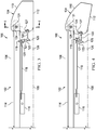
Figure 1 is a top view of a rotorcraft blade assembly with a blade tip in a fully extended configuration according to an embodiment of this disclosure; -
Figure 2 is a top view of the rotorcraft blade assembly ofFigure 1 with the blade tip in a fully retracted configuration; -
Figure 3 is a top schematic view of the rotorcraft blade assembly ofFigure 1 with the blade tip in a fully extended configuration; -
Figure 4 is a top schematic view of the rotorcraft blade assembly ofFigure 1 with the blade tip in a fully retracted configuration; -
Figure 5 is an oblique view of the rotorcraft blade assembly ofFigure 1 with the blade tip in a fully extended configuration; -
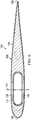
Figure 6 is a cross-sectional view of the rotorcraft blade assembly taken along cutting line 6-6 ofFigure 3 ; -
Figure 7 is an oblique view of the rotorcraft blade assembly ofFigure 1 with the blade tip in a fully extended configuration; -
Figure 8 is an oblique view of the rotorcraft blade assembly ofFigure 1 with the blade tip in a fully retracted configuration; -
Figure 9 is an oblique view of a helicopter comprising a rotorcraft blade assembly according to another embodiment; -
Figure 10 is another oblique view of the helicopter ofFigure 9 ; and -
Figure 11 is a flowchart of a method of operating a helicopter. - In this disclosure, reference may be made to the spatial relationships between various components and to the spatial orientation of various aspects of components as the devices are depicted in the attached drawings. However, as will be recognized by those skilled in the art after a complete reading of this disclosure, the devices, members, apparatuses, etc. described herein may be positioned in any desired orientation. Thus, the use of terms such as "above," "below," "upper," "lower," or other like terms to describe a spatial relationship between various components or to describe the spatial orientation of aspects of such components should be understood to describe a relative relationship between the components or a spatial orientation of aspects of such components, respectively, as the device described herein may be oriented in any desired direction.
- Most generally, embodiments disclosed herein provide a reconfigurable blade tip that allows adjustment of a tip angle relative to a main blade body during flight so that the blade can be optimized for a particular flight speed and/or flight regime. Accordingly, a tip Mach number can be managed while in flight to accommodate a desired speed range or flight envelope. In some embodiments, the blade tip can be retracted toward a fully retracted position to reduce tip Mach numbers. By changing the blade tip position, tip shockwaves and tip vortexes can be managed, in some cases, to reduce the compressible waves at the blade tip.
- Referring to
Figures 1-8 , arotorcraft blade assembly 100 is shown as comprising amain body 102 and ablade tip 104 that is selectively movable relative to themain body 102. Most generally, themain body 102 comprises a leadingblade profile 106 and atrailing blade profile 108. Similarly, theblade tip 104 comprises a leadingtip profile 110 and atrailing tip profile 112. Therotorcraft blade assembly 100 comprises astructural spar 114 that serves as a primary path for centrifugal force acting on therotorcraft blade assembly 100. In this embodiment, thespar 114 comprises a tubular structure that is constructed of composite materials. In alternative embodiments, a spar may be substantially solid. In other embodiments, spar may be constructed of materials other than composite material, such as, but no limited to, metals. Thespar 114 serves as a primary structural element for themain body 102. - The
rotorcraft blade assembly 100 further comprises alinear motor 116 fixed relative to themain body 102. In this embodiment, thelinear motor 116 is attached to thespar 114. Thelinear motor 116 is configured to push and/or pull aninput rod 118 in directions generally along the length of therotorcraft blade assembly 100. Theinput rod 118 is connected to abellcrank 120 via aninput pivot connection 119 to acrank arm 123 and thecrank arm 123 is further connected to anoutput rod 122 via anoutput pivot connection 125. Thecrank arm 123 is pivotably secured relative to themain body 102 using acrank pin 121 or other suitable structure and thecrank pin 121 is disposed between theinput pivot connection 119 and theoutput pivot connection 125. Actuation of thelinear motor 116 can selectively translate theinput rod 118 along the length of therotorcraft blade assembly 100 toward thebellcrank 120 to rotate thebellcrank 120 about thecrank pin 121 and resultantly translate theoutput rod 122 along the length of therotorcraft blade assembly 100 toward thelinear motor 116. In response to theinput rod 118 being moved toward thebellcrank 120 and theoutput rod 122 being moved toward thelinear motor 116, theblade tip 104 is urged toward a relatively more retracted position and/or to a fully retracted position, the fully retracted position being shown inFigures 2 ,4 , and8 . In some cases, thebellcrank 120 can be configured to provide a change in mechanical advantage by providing different spacing between theinput pivot connection 119 and thecrank pin 121 as compared to the spacing between thecrank pin 121 and theoutput pivot connection 125. - To achieve an opposite movement of the
blade tip 104, thelinear motor 116 can be actuated to selectively translate theinput rod 118 along the length of therotorcraft blade assembly 100 toward thelinear motor 116 to rotate thebellcrank 120 about thecrank pin 121 and resultantly translate theoutput rod 122 along the length of therotorcraft blade assembly 100 away from thelinear motor 116. In response to theinput rod 118 being moved toward thelinear motor 116, theblade tip 104 is urged toward a relatively more extended position and/or to a fully extended position, the fully extended position being shown inFigures 1 ,3 ,5 , and7 . Theoutput rod 122 is connected to theblade tip 104 via atip pivot connection 127. Each of theinput pivot connection 119,output pivot connection 125, andtip pivot connection 127 can be achieved by utilizing pins and forked rod end connectors. - Because the
blade tip 104 is movably connected to themain body 102 utilizing apin 124 and/or associated bearings and/or bushings, operation of thelinear motor 116 disposed near a center of gravity of therotorcraft blade assembly 100 can cause rotation of theblade tip 104 about acentral axis 131 of thepin 124. In some embodiments, thepin 124 extends through thespar 114, theblade tip 104 andouter skin 126 of themain body 102. In some embodiments, theouter skin 126 may be configured to lay over thepin 124. In this embodiment, thepin 124 extends through anupper aperture 132 of thespar 114 and through alower aperture 134 of thespar 114, with thepin 124, theupper aperture 132, and thelower aperture 134 being substantially coaxially disposed with thecentral axis 131. - Some rotorcraft blades comprise complicated shapes along their leading edges. Accordingly, some blade tips contemplated by this disclosure comprise an at least partially torus-shaped leading tip profile so that although blade tip is rotated about the pin, the clearance and/or type of contact between the blade tip and the main body remains substantially constant. In this embodiment, the leading
tip profile 110 remains in contact with themain body 102, namely, at least partially nested behind leadingblade profile 106. Accordingly, although theblade tip 104 is movable, the rotorcraft blade assembly100 comprises consistently faired leading surfaces and/or surface transitions. In operation, therotorcraft blade assemblies 100 can be rotated about a mast axis of a helicopter and during such rotation about the mast axis, theblade tip 104 can be moved relative to themain body 102. - In some embodiments, the blade tip is received inside the main body and/or is nested relative to the main body to be offset and/or complimentary to the main body. In some embodiments, the trailing blade profile is configured so that the
outer skin 126 of the main body is not sealed near the blade tip so that theblade tip 104 can be slid between the upper and lower portions of theouter skin 126. In some embodiments, theouter skin 126 can comprise as few as three to six plies of composite material and can be about fifty thousandths of an inch thick. In some cases, drag, vibration, and noise can be managed and/or reduced by moving theblade tip 104 relative to themain body 102. - Referring now to
Figures 9 and10 , ahelicopter 200 is shown.Helicopter 200 comprises arotor system 202 comprising arotorcraft blade assembly 203, afuselage 208, atail 210, andlanding gear 212. Therotorcraft blade assembly 203 comprises amain body 204 and amovable blade tip 206. Theblade tip 206 is movable relative to themain body 204 is a substantially similar manner asblade tip 104 is movable relative tomain body 102. However, in this embodiment, theblade tip 206 does not maintain contact with themain body 204 at the lengthwise end of themain body 204. Agap 214 is provided at atrailing blade profile 216 of the main body into whichgap 214 portions of theblade tip 206 may be selectively received. In this embodiment, a gap distance varies (as a function of an elasticity of the trailing blade profile 216) to accommodate any changes in thickness of theblade tip 206 received within thegap 214. In operation, therotorcraft blade assemblies 203 can be rotated about amast axis 218 of thehelicopter 200 and during such rotation about themast axis 218, theblade tip 206 can be moved relative to themain body 204. - Referring now to
Figure 11 , a flowchart of amethod 300 of operating a helicopter (e.g.,helicopter 200 or a helicopter comprising rotorcraft blade assembly 100) is shown. Themethod 300 begins atblock 302 by providing a helicopter comprising a rotorcraft blade assembly (e.g.,rotorcraft blade assemblies 100 or 203) comprising a main body (e.g.,main body 102 or 204) and a blade tip (e.g.,blade tip 104 or 206) selectively moveable relative to the main body. Themethod 300 continues atblock 304 by rotating the rotorcraft blade assembly about a mast axis of the helicopter. Themethod 300 further continues atblock 306 by, while rotating the rotorcraft blade assembly about the mast axis, selectively moving the blade tip relative to the main body. In alternative embodiments, a method of operating a helicopter my comprise moving the blade tip relative to the main body while the rotorcraft blade assembly is substantially stationary relative to the mast axis. - Explained another way, a variable-swept blade tip device and associated mechanism and interface layout for helicopter rotor blades is disclosed. A linear actuator can provide motive force to rotate a shaped blade tip about a pivot point through the main CF-bearing structural tube spar in the blade. A bellcrank or other mechanism allow actuation in the small volume afterbody of typical blades without locating the actuator in the same constrained space and maintaining a less severe CG shift. The blade tip is shaped to maintain contact on the leading edge through a sweep profile and blade trailing edge skins are flexible enough to allow the tip trailing edge to nest within the afterbody while maintaining contact with skin inner mold lines.
- At least one embodiment is disclosed, and variations, combinations, and/or modifications of the embodiment(s) and/or features of the embodiment(s) made by a person having ordinary skill in the art are within the scope of this disclosure. Alternative embodiments that result from combining, integrating, and/or omitting features of the embodiment(s) are also within the scope of this disclosure. Where numerical ranges or limitations are expressly stated, such express ranges or limitations should be understood to include iterative ranges or limitations of like magnitude falling within the expressly stated ranges or limitations (e.g., from about 1 to about 10 includes, 2, 3, 4, etc.; greater than 0.10 includes 0.11, 0.12, 0.13, etc.). For example, whenever a numerical range with a lower limit, R1, and an upper limit, Ru, is disclosed, any number falling within the range is specifically disclosed. In particular, the following numbers within the range are specifically disclosed: R=R1 +k * (Ru-R1), wherein k is a variable ranging from 1 percent to 100 percent with a 1 percent increment, i.e., k is 1 percent, 2 percent, 3 percent, 4 percent, 5 percent,...50 percent, 51 percent, 52 percent,..., 95 percent, 96 percent, 95 percent, 98 percent, 99 percent, or 100 percent. Moreover, any numerical range defined by two R numbers as defined in the above is also specifically disclosed. Use of the term "optionally" with respect to any element of a claim means that the element is required, or alternatively, the element is not required, both alternatives being within the scope of the claim. Use of broader terms such as comprises, includes, and having should be understood to provide support for narrower terms such as consisting of, consisting essentially of, and comprised substantially of. Accordingly, the scope of protection is not limited by the description set out above but is defined by the claims that follow, that scope including all equivalents of the subject matter of the claims. Each and every claim is incorporated as further disclosure into the specification and the claims are embodiment(s) of the present invention. Also, the phrases "at least one of A, B, and C" and "A and/or B and/or C" should each be interpreted to include only A, only B, only C, or any combination of A, B, and C.
Claims (15)
- A rotorcraft blade assembly, comprising:a main body; anda blade tip movable relative to the main body.
- The rotorcraft blade assembly of claim 1, wherein a contact between the blade tip and the main body is maintained throughout movement of the blade tip relative to the main body.
- The rotorcraft blade assembly of claim 1 or of claim 2, wherein the blade tip is rotatable relative to the main body.
- The rotorcraft blade assembly of claim 3, wherein the blade tip is connected to the main body using a pin.
- The rotorcraft blade assembly of claim 4, wherein the pin extends through a spar of the main body.
- The rotorcraft blade assembly of claim 5, wherein the spar is tubular.
- The rotorcraft blade assembly of claim 1 or of any of claims 2 to 6, wherein movement of the blade tip relative to the main body is accomplished using at least one of a linear motor disposed within the main body and a bellcrank disposed within the main body.
- The rotor blade assembly of claim 1 or of any of claims 2 to 7, wherein a trailing blade profile is flexible and configured to receive a portion of the blade tip in a gap formed by the trailing blade profile.
- A helicopter, comprising:a mast axis; anda rotorcraft blade assembly, comprising:a main body; anda blade tip movable relative to the main body;wherein the rotorcraft blade assembly is selectively rotatable about the mast axis.
- The helicopter of claim 9, wherein a contact between the blade tip and the main body is maintained throughout movement of the blade tip relative to the main body.
- The helicopter of claim 9 or of claim 10, wherein the blade tip is rotatable relative to the main body.
- The helicopter of claim 9, wherein a contact between the blade tip and the main body is maintained throughout movement of the blade tip relative to the main body.
- The helicopter of claim 12, wherein:-(i) the maintained contact comprises contact between the blade tip and a leading blade profile of the main body; or(ii) the maintained contact comprises contact between the blade tip and a trailing blade profile of the main body.
- A method of operating a helicopter, comprising:providing a helicopter comprising:a rotorcraft blade assembly, comprising:a main body; anda blade tip that is selectively movable relative to the main body; andmoving the blade tip relative to the main body.
- The method of claim 14, wherein the moving the blade tip relative to the main body is performed while rotating the rotorcraft blade assembly about a mast axis of the helicopter, and optionally or preferably further comprising:maintaining a contact between the blade tip and the main body throughout movement of the blade tip relative to the main body.
Applications Claiming Priority (2)
| Application Number | Priority Date | Filing Date | Title |
|---|---|---|---|
| US201762468342P | 2017-03-07 | 2017-03-07 | |
| US15/871,002 US10787251B2 (en) | 2017-03-07 | 2018-01-14 | Variable sweep rotorcraft blade tip |
Publications (2)
| Publication Number | Publication Date |
|---|---|
| EP3372497A1 true EP3372497A1 (en) | 2018-09-12 |
| EP3372497B1 EP3372497B1 (en) | 2019-08-28 |
Family
ID=61256618
Family Applications (1)
| Application Number | Title | Priority Date | Filing Date |
|---|---|---|---|
| EP18157737.0A Active EP3372497B1 (en) | 2017-03-07 | 2018-02-20 | Variable sweep rotorcraft blade tip |
Country Status (2)
| Country | Link |
|---|---|
| US (1) | US10787251B2 (en) |
| EP (1) | EP3372497B1 (en) |
Families Citing this family (3)
| Publication number | Priority date | Publication date | Assignee | Title |
|---|---|---|---|---|
| US12202600B1 (en) | 2023-10-06 | 2025-01-21 | Textron Innovations Inc. | High-speed tiltrotor aircraft having a variable-sweep wing |
| US12352185B1 (en) * | 2024-07-19 | 2025-07-08 | Rtx Corporation | Open rotor variable pitch blade with retracting inboard trailing edge |
| CN120364130B (en) * | 2025-06-26 | 2025-10-14 | 中国东方航空设备集成有限公司 | A variable-sweep rotor |
Citations (16)
| Publication number | Priority date | Publication date | Assignee | Title |
|---|---|---|---|---|
| FR817657A (en) * | 1936-05-15 | 1937-09-08 | Asboth Helicopters Ltd | Rotary wing system for rotary wing aircraft |
| US2451541A (en) * | 1945-05-24 | 1948-10-19 | United Aireraft Corp | Dynamic balancer for rotor blades |
| US3005496A (en) * | 1959-08-24 | 1961-10-24 | Hiller Aircraft Corp | Airfoil boundary layer control means |
| DE1134593B (en) * | 1960-11-14 | 1962-08-09 | Boelkow Entwicklungen Kg | Rotor for rotary wing aircraft |
| US3814351A (en) * | 1972-12-06 | 1974-06-04 | United Aircraft Corp | Coaxial rotor yaw control |
| JPH0481391A (en) * | 1990-07-23 | 1992-03-16 | Mitsubishi Heavy Ind Ltd | Helicopter |
| JPH04176795A (en) * | 1990-11-13 | 1992-06-24 | Mitsubishi Heavy Ind Ltd | Helicopter rotating blade |
| JPH05694A (en) * | 1991-06-25 | 1993-01-08 | Mitsubishi Heavy Ind Ltd | Rotor blade of helicopter |
| EP1127786A1 (en) * | 2000-02-23 | 2001-08-29 | Fuji Jukogyo Kabushiki Kaisha | Rotary blade of helicopter |
| US6394397B1 (en) * | 2000-12-06 | 2002-05-28 | The Boeing Company | Lifting surface with active variable tip member and method for influencing lifting surface behavior therewith |
| WO2006098749A1 (en) * | 2004-07-23 | 2006-09-21 | The Boeing Company | System and method for improved rotor tip performance |
| KR20100111983A (en) * | 2009-04-08 | 2010-10-18 | 건국대학교 산학협력단 | Rotor blade for rotorcraft to change sweep-back angle of the blade tip actively |
| EP2740663A1 (en) * | 2012-12-05 | 2014-06-11 | The Boeing Company | Apparatus, system, and method for pitching and twisting a blade of a rotorcraft |
| US20150360773A1 (en) * | 2013-09-27 | 2015-12-17 | Dann M Allen | Helicopter rotor with a mechanical means for configuring rotor tips to control brown outs |
| US20160075430A1 (en) * | 2014-09-15 | 2016-03-17 | Bell Helicopter Textron Inc. | Variable anhedral tip rotor blade |
| EP3293112A1 (en) * | 2016-09-07 | 2018-03-14 | Leonardo S.p.A. | Rotor for a hover-capable aircraft and related method of control |
Family Cites Families (5)
| Publication number | Priority date | Publication date | Assignee | Title |
|---|---|---|---|---|
| US8800145B2 (en) * | 2008-12-30 | 2014-08-12 | Sikorsky Aircraft Corporation | Refurbishing method and system for a main rotor blade spar |
| EP2514668B1 (en) * | 2011-04-18 | 2016-11-02 | Claverham Limited | Active gurney flap |
| US9908612B2 (en) * | 2011-10-01 | 2018-03-06 | The Boeing Company | Fold wing tip having stub spar |
| WO2015133980A1 (en) * | 2014-03-03 | 2015-09-11 | Sikorsky Aircraft Corporation | Single actuator blade fold linkage |
| US10569906B2 (en) * | 2016-06-30 | 2020-02-25 | Sikorsky Aircraft Corporation | Apparatus and methods for making rotorcraft rotor blades |
-
2018
- 2018-01-14 US US15/871,002 patent/US10787251B2/en active Active
- 2018-02-20 EP EP18157737.0A patent/EP3372497B1/en active Active
Patent Citations (16)
| Publication number | Priority date | Publication date | Assignee | Title |
|---|---|---|---|---|
| FR817657A (en) * | 1936-05-15 | 1937-09-08 | Asboth Helicopters Ltd | Rotary wing system for rotary wing aircraft |
| US2451541A (en) * | 1945-05-24 | 1948-10-19 | United Aireraft Corp | Dynamic balancer for rotor blades |
| US3005496A (en) * | 1959-08-24 | 1961-10-24 | Hiller Aircraft Corp | Airfoil boundary layer control means |
| DE1134593B (en) * | 1960-11-14 | 1962-08-09 | Boelkow Entwicklungen Kg | Rotor for rotary wing aircraft |
| US3814351A (en) * | 1972-12-06 | 1974-06-04 | United Aircraft Corp | Coaxial rotor yaw control |
| JPH0481391A (en) * | 1990-07-23 | 1992-03-16 | Mitsubishi Heavy Ind Ltd | Helicopter |
| JPH04176795A (en) * | 1990-11-13 | 1992-06-24 | Mitsubishi Heavy Ind Ltd | Helicopter rotating blade |
| JPH05694A (en) * | 1991-06-25 | 1993-01-08 | Mitsubishi Heavy Ind Ltd | Rotor blade of helicopter |
| EP1127786A1 (en) * | 2000-02-23 | 2001-08-29 | Fuji Jukogyo Kabushiki Kaisha | Rotary blade of helicopter |
| US6394397B1 (en) * | 2000-12-06 | 2002-05-28 | The Boeing Company | Lifting surface with active variable tip member and method for influencing lifting surface behavior therewith |
| WO2006098749A1 (en) * | 2004-07-23 | 2006-09-21 | The Boeing Company | System and method for improved rotor tip performance |
| KR20100111983A (en) * | 2009-04-08 | 2010-10-18 | 건국대학교 산학협력단 | Rotor blade for rotorcraft to change sweep-back angle of the blade tip actively |
| EP2740663A1 (en) * | 2012-12-05 | 2014-06-11 | The Boeing Company | Apparatus, system, and method for pitching and twisting a blade of a rotorcraft |
| US20150360773A1 (en) * | 2013-09-27 | 2015-12-17 | Dann M Allen | Helicopter rotor with a mechanical means for configuring rotor tips to control brown outs |
| US20160075430A1 (en) * | 2014-09-15 | 2016-03-17 | Bell Helicopter Textron Inc. | Variable anhedral tip rotor blade |
| EP3293112A1 (en) * | 2016-09-07 | 2018-03-14 | Leonardo S.p.A. | Rotor for a hover-capable aircraft and related method of control |
Also Published As
| Publication number | Publication date |
|---|---|
| US10787251B2 (en) | 2020-09-29 |
| US20180257767A1 (en) | 2018-09-13 |
| EP3372497B1 (en) | 2019-08-28 |
Similar Documents
| Publication | Publication Date | Title |
|---|---|---|
| EP3464061B1 (en) | Propeller-hub assembly with folding blades for vtol aircraft | |
| JP6108804B2 (en) | Rear edge tip of wing variable camber | |
| US6045096A (en) | Variable camber airfoil | |
| US8272599B2 (en) | Control lever assembly for a tilt-rotor aircraft | |
| JP7433254B2 (en) | tail sitter | |
| US9567070B2 (en) | Tiltrotor control system with two rise/fall actuators | |
| US10787251B2 (en) | Variable sweep rotorcraft blade tip | |
| US3921942A (en) | Rudder boundary layer control device | |
| KR102069783B1 (en) | Helicopter aerofoil with trailing edge flap | |
| EP2604513A1 (en) | Blade-pitch control system with feedback lever | |
| US10882611B2 (en) | Augmented swashplate assembly | |
| EP3310652B1 (en) | Aircraft wing system | |
| IL153055A (en) | Aerodynamic control surface system | |
| US11053003B2 (en) | Cyclorotor thrust control, transmission and mounting system | |
| EP2982597B1 (en) | Tail spar spring | |
| KR20130077242A (en) | Tilt rotor aircraft | |
| GB1083309A (en) | Variable-geometry aircraft | |
| CN116635299B (en) | Aircraft with a plurality of aircraft seats | |
| CN111448135A (en) | Thrust reversing type airplane and control method thereof | |
| GB1308023A (en) | Bladed rotors | |
| US3129769A (en) | Fail safe device for servo flap controlled rotor blades | |
| US10343764B2 (en) | Aircraft wheel fairing drag device | |
| KR101663814B1 (en) | Tail-sitter airplane | |
| US11492098B2 (en) | High-lift device, wing, and aircraft | |
| WO2016200458A2 (en) | Mono-cyclic swashplate |
Legal Events
| Date | Code | Title | Description |
|---|---|---|---|
| STAA | Information on the status of an ep patent application or granted ep patent |
Free format text: STATUS: EXAMINATION IS IN PROGRESS |
|
| PUAI | Public reference made under article 153(3) epc to a published international application that has entered the european phase |
Free format text: ORIGINAL CODE: 0009012 |
|
| 17P | Request for examination filed |
Effective date: 20180220 |
|
| AK | Designated contracting states |
Kind code of ref document: A1 Designated state(s): AL AT BE BG CH CY CZ DE DK EE ES FI FR GB GR HR HU IE IS IT LI LT LU LV MC MK MT NL NO PL PT RO RS SE SI SK SM TR |
|
| AX | Request for extension of the european patent |
Extension state: BA ME |
|
| GRAP | Despatch of communication of intention to grant a patent |
Free format text: ORIGINAL CODE: EPIDOSNIGR1 |
|
| STAA | Information on the status of an ep patent application or granted ep patent |
Free format text: STATUS: GRANT OF PATENT IS INTENDED |
|
| INTG | Intention to grant announced |
Effective date: 20190405 |
|
| GRAS | Grant fee paid |
Free format text: ORIGINAL CODE: EPIDOSNIGR3 |
|
| GRAA | (expected) grant |
Free format text: ORIGINAL CODE: 0009210 |
|
| STAA | Information on the status of an ep patent application or granted ep patent |
Free format text: STATUS: THE PATENT HAS BEEN GRANTED |
|
| AK | Designated contracting states |
Kind code of ref document: B1 Designated state(s): AL AT BE BG CH CY CZ DE DK EE ES FI FR GB GR HR HU IE IS IT LI LT LU LV MC MK MT NL NO PL PT RO RS SE SI SK SM TR |
|
| REG | Reference to a national code |
Ref country code: GB Ref legal event code: FG4D |
|
| REG | Reference to a national code |
Ref country code: CH Ref legal event code: EP |
|
| REG | Reference to a national code |
Ref country code: DE Ref legal event code: R096 Ref document number: 602018000491 Country of ref document: DE |
|
| REG | Reference to a national code |
Ref country code: AT Ref legal event code: REF Ref document number: 1172090 Country of ref document: AT Kind code of ref document: T Effective date: 20190915 |
|
| REG | Reference to a national code |
Ref country code: IE Ref legal event code: FG4D |
|
| REG | Reference to a national code |
Ref country code: NL Ref legal event code: MP Effective date: 20190828 |
|
| REG | Reference to a national code |
Ref country code: LT Ref legal event code: MG4D |
|
| PG25 | Lapsed in a contracting state [announced via postgrant information from national office to epo] |
Ref country code: PT Free format text: LAPSE BECAUSE OF FAILURE TO SUBMIT A TRANSLATION OF THE DESCRIPTION OR TO PAY THE FEE WITHIN THE PRESCRIBED TIME-LIMIT Effective date: 20191230 Ref country code: FI Free format text: LAPSE BECAUSE OF FAILURE TO SUBMIT A TRANSLATION OF THE DESCRIPTION OR TO PAY THE FEE WITHIN THE PRESCRIBED TIME-LIMIT Effective date: 20190828 Ref country code: LT Free format text: LAPSE BECAUSE OF FAILURE TO SUBMIT A TRANSLATION OF THE DESCRIPTION OR TO PAY THE FEE WITHIN THE PRESCRIBED TIME-LIMIT Effective date: 20190828 Ref country code: NL Free format text: LAPSE BECAUSE OF FAILURE TO SUBMIT A TRANSLATION OF THE DESCRIPTION OR TO PAY THE FEE WITHIN THE PRESCRIBED TIME-LIMIT Effective date: 20190828 Ref country code: SE Free format text: LAPSE BECAUSE OF FAILURE TO SUBMIT A TRANSLATION OF THE DESCRIPTION OR TO PAY THE FEE WITHIN THE PRESCRIBED TIME-LIMIT Effective date: 20190828 Ref country code: HR Free format text: LAPSE BECAUSE OF FAILURE TO SUBMIT A TRANSLATION OF THE DESCRIPTION OR TO PAY THE FEE WITHIN THE PRESCRIBED TIME-LIMIT Effective date: 20190828 Ref country code: BG Free format text: LAPSE BECAUSE OF FAILURE TO SUBMIT A TRANSLATION OF THE DESCRIPTION OR TO PAY THE FEE WITHIN THE PRESCRIBED TIME-LIMIT Effective date: 20191128 Ref country code: NO Free format text: LAPSE BECAUSE OF FAILURE TO SUBMIT A TRANSLATION OF THE DESCRIPTION OR TO PAY THE FEE WITHIN THE PRESCRIBED TIME-LIMIT Effective date: 20191128 |
|
| PG25 | Lapsed in a contracting state [announced via postgrant information from national office to epo] |
Ref country code: AL Free format text: LAPSE BECAUSE OF FAILURE TO SUBMIT A TRANSLATION OF THE DESCRIPTION OR TO PAY THE FEE WITHIN THE PRESCRIBED TIME-LIMIT Effective date: 20190828 Ref country code: IS Free format text: LAPSE BECAUSE OF FAILURE TO SUBMIT A TRANSLATION OF THE DESCRIPTION OR TO PAY THE FEE WITHIN THE PRESCRIBED TIME-LIMIT Effective date: 20191228 Ref country code: LV Free format text: LAPSE BECAUSE OF FAILURE TO SUBMIT A TRANSLATION OF THE DESCRIPTION OR TO PAY THE FEE WITHIN THE PRESCRIBED TIME-LIMIT Effective date: 20190828 Ref country code: GR Free format text: LAPSE BECAUSE OF FAILURE TO SUBMIT A TRANSLATION OF THE DESCRIPTION OR TO PAY THE FEE WITHIN THE PRESCRIBED TIME-LIMIT Effective date: 20191129 Ref country code: RS Free format text: LAPSE BECAUSE OF FAILURE TO SUBMIT A TRANSLATION OF THE DESCRIPTION OR TO PAY THE FEE WITHIN THE PRESCRIBED TIME-LIMIT Effective date: 20190828 Ref country code: ES Free format text: LAPSE BECAUSE OF FAILURE TO SUBMIT A TRANSLATION OF THE DESCRIPTION OR TO PAY THE FEE WITHIN THE PRESCRIBED TIME-LIMIT Effective date: 20190828 |
|
| REG | Reference to a national code |
Ref country code: AT Ref legal event code: MK05 Ref document number: 1172090 Country of ref document: AT Kind code of ref document: T Effective date: 20190828 |
|
| PG25 | Lapsed in a contracting state [announced via postgrant information from national office to epo] |
Ref country code: TR Free format text: LAPSE BECAUSE OF FAILURE TO SUBMIT A TRANSLATION OF THE DESCRIPTION OR TO PAY THE FEE WITHIN THE PRESCRIBED TIME-LIMIT Effective date: 20190828 |
|
| PG25 | Lapsed in a contracting state [announced via postgrant information from national office to epo] |
Ref country code: DK Free format text: LAPSE BECAUSE OF FAILURE TO SUBMIT A TRANSLATION OF THE DESCRIPTION OR TO PAY THE FEE WITHIN THE PRESCRIBED TIME-LIMIT Effective date: 20190828 Ref country code: EE Free format text: LAPSE BECAUSE OF FAILURE TO SUBMIT A TRANSLATION OF THE DESCRIPTION OR TO PAY THE FEE WITHIN THE PRESCRIBED TIME-LIMIT Effective date: 20190828 Ref country code: AT Free format text: LAPSE BECAUSE OF FAILURE TO SUBMIT A TRANSLATION OF THE DESCRIPTION OR TO PAY THE FEE WITHIN THE PRESCRIBED TIME-LIMIT Effective date: 20190828 Ref country code: PL Free format text: LAPSE BECAUSE OF FAILURE TO SUBMIT A TRANSLATION OF THE DESCRIPTION OR TO PAY THE FEE WITHIN THE PRESCRIBED TIME-LIMIT Effective date: 20190828 Ref country code: RO Free format text: LAPSE BECAUSE OF FAILURE TO SUBMIT A TRANSLATION OF THE DESCRIPTION OR TO PAY THE FEE WITHIN THE PRESCRIBED TIME-LIMIT Effective date: 20190828 |
|
| PG25 | Lapsed in a contracting state [announced via postgrant information from national office to epo] |
Ref country code: SM Free format text: LAPSE BECAUSE OF FAILURE TO SUBMIT A TRANSLATION OF THE DESCRIPTION OR TO PAY THE FEE WITHIN THE PRESCRIBED TIME-LIMIT Effective date: 20190828 Ref country code: SK Free format text: LAPSE BECAUSE OF FAILURE TO SUBMIT A TRANSLATION OF THE DESCRIPTION OR TO PAY THE FEE WITHIN THE PRESCRIBED TIME-LIMIT Effective date: 20190828 Ref country code: IS Free format text: LAPSE BECAUSE OF FAILURE TO SUBMIT A TRANSLATION OF THE DESCRIPTION OR TO PAY THE FEE WITHIN THE PRESCRIBED TIME-LIMIT Effective date: 20200224 Ref country code: CZ Free format text: LAPSE BECAUSE OF FAILURE TO SUBMIT A TRANSLATION OF THE DESCRIPTION OR TO PAY THE FEE WITHIN THE PRESCRIBED TIME-LIMIT Effective date: 20190828 |
|
| REG | Reference to a national code |
Ref country code: DE Ref legal event code: R097 Ref document number: 602018000491 Country of ref document: DE |
|
| PLBE | No opposition filed within time limit |
Free format text: ORIGINAL CODE: 0009261 |
|
| STAA | Information on the status of an ep patent application or granted ep patent |
Free format text: STATUS: NO OPPOSITION FILED WITHIN TIME LIMIT |
|
| PG2D | Information on lapse in contracting state deleted |
Ref country code: IS |
|
| 26N | No opposition filed |
Effective date: 20200603 |
|
| PG25 | Lapsed in a contracting state [announced via postgrant information from national office to epo] |
Ref country code: SI Free format text: LAPSE BECAUSE OF FAILURE TO SUBMIT A TRANSLATION OF THE DESCRIPTION OR TO PAY THE FEE WITHIN THE PRESCRIBED TIME-LIMIT Effective date: 20190828 |
|
| REG | Reference to a national code |
Ref country code: BE Ref legal event code: MM Effective date: 20200229 |
|
| PG25 | Lapsed in a contracting state [announced via postgrant information from national office to epo] |
Ref country code: MC Free format text: LAPSE BECAUSE OF FAILURE TO SUBMIT A TRANSLATION OF THE DESCRIPTION OR TO PAY THE FEE WITHIN THE PRESCRIBED TIME-LIMIT Effective date: 20190828 Ref country code: LU Free format text: LAPSE BECAUSE OF NON-PAYMENT OF DUE FEES Effective date: 20200220 |
|
| PG25 | Lapsed in a contracting state [announced via postgrant information from national office to epo] |
Ref country code: IE Free format text: LAPSE BECAUSE OF NON-PAYMENT OF DUE FEES Effective date: 20200220 |
|
| PG25 | Lapsed in a contracting state [announced via postgrant information from national office to epo] |
Ref country code: BE Free format text: LAPSE BECAUSE OF NON-PAYMENT OF DUE FEES Effective date: 20200229 |
|
| PG25 | Lapsed in a contracting state [announced via postgrant information from national office to epo] |
Ref country code: LI Free format text: LAPSE BECAUSE OF NON-PAYMENT OF DUE FEES Effective date: 20210228 Ref country code: CH Free format text: LAPSE BECAUSE OF NON-PAYMENT OF DUE FEES Effective date: 20210228 |
|
| PG25 | Lapsed in a contracting state [announced via postgrant information from national office to epo] |
Ref country code: MT Free format text: LAPSE BECAUSE OF FAILURE TO SUBMIT A TRANSLATION OF THE DESCRIPTION OR TO PAY THE FEE WITHIN THE PRESCRIBED TIME-LIMIT Effective date: 20190828 Ref country code: CY Free format text: LAPSE BECAUSE OF FAILURE TO SUBMIT A TRANSLATION OF THE DESCRIPTION OR TO PAY THE FEE WITHIN THE PRESCRIBED TIME-LIMIT Effective date: 20190828 |
|
| PG25 | Lapsed in a contracting state [announced via postgrant information from national office to epo] |
Ref country code: MK Free format text: LAPSE BECAUSE OF FAILURE TO SUBMIT A TRANSLATION OF THE DESCRIPTION OR TO PAY THE FEE WITHIN THE PRESCRIBED TIME-LIMIT Effective date: 20190828 |
|
| P01 | Opt-out of the competence of the unified patent court (upc) registered |
Effective date: 20230602 |
|
| PGFP | Annual fee paid to national office [announced via postgrant information from national office to epo] |
Ref country code: GB Payment date: 20260227 Year of fee payment: 9 |
|
| PGFP | Annual fee paid to national office [announced via postgrant information from national office to epo] |
Ref country code: DE Payment date: 20260227 Year of fee payment: 9 |
|
| PGFP | Annual fee paid to national office [announced via postgrant information from national office to epo] |
Ref country code: IT Payment date: 20260219 Year of fee payment: 9 |
|
| PGFP | Annual fee paid to national office [announced via postgrant information from national office to epo] |
Ref country code: FR Payment date: 20260225 Year of fee payment: 9 |