EP3372490A1 - Flexible control surfaces and related methods - Google Patents
Flexible control surfaces and related methods Download PDFInfo
- Publication number
- EP3372490A1 EP3372490A1 EP18160272.3A EP18160272A EP3372490A1 EP 3372490 A1 EP3372490 A1 EP 3372490A1 EP 18160272 A EP18160272 A EP 18160272A EP 3372490 A1 EP3372490 A1 EP 3372490A1
- Authority
- EP
- European Patent Office
- Prior art keywords
- control surface
- skin
- flexible
- airfoil
- perforations
- Prior art date
- Legal status (The legal status is an assumption and is not a legal conclusion. Google has not performed a legal analysis and makes no representation as to the accuracy of the status listed.)
- Granted
Links
Images





Classifications
-
- B—PERFORMING OPERATIONS; TRANSPORTING
- B64—AIRCRAFT; AVIATION; COSMONAUTICS
- B64C—AEROPLANES; HELICOPTERS
- B64C9/00—Adjustable control surfaces or members, e.g. rudders
- B64C9/14—Adjustable control surfaces or members, e.g. rudders forming slots
- B64C9/16—Adjustable control surfaces or members, e.g. rudders forming slots at the rear of the wing
-
- B—PERFORMING OPERATIONS; TRANSPORTING
- B64—AIRCRAFT; AVIATION; COSMONAUTICS
- B64C—AEROPLANES; HELICOPTERS
- B64C3/00—Wings
- B64C3/26—Construction, shape, or attachment of separate skins, e.g. panels
-
- B—PERFORMING OPERATIONS; TRANSPORTING
- B64—AIRCRAFT; AVIATION; COSMONAUTICS
- B64C—AEROPLANES; HELICOPTERS
- B64C3/00—Wings
- B64C3/28—Leading or trailing edges attached to primary structures, e.g. forming fixed slots
-
- B—PERFORMING OPERATIONS; TRANSPORTING
- B64—AIRCRAFT; AVIATION; COSMONAUTICS
- B64C—AEROPLANES; HELICOPTERS
- B64C3/00—Wings
- B64C3/38—Adjustment of complete wings or parts thereof
- B64C3/44—Varying camber
- B64C3/48—Varying camber by relatively-movable parts of wing structures
-
- B—PERFORMING OPERATIONS; TRANSPORTING
- B64—AIRCRAFT; AVIATION; COSMONAUTICS
- B64C—AEROPLANES; HELICOPTERS
- B64C3/00—Wings
- B64C3/38—Adjustment of complete wings or parts thereof
- B64C3/52—Warping
-
- B—PERFORMING OPERATIONS; TRANSPORTING
- B64—AIRCRAFT; AVIATION; COSMONAUTICS
- B64C—AEROPLANES; HELICOPTERS
- B64C9/00—Adjustable control surfaces or members, e.g. rudders
- B64C9/08—Adjustable control surfaces or members, e.g. rudders bodily displaceable
-
- B—PERFORMING OPERATIONS; TRANSPORTING
- B64—AIRCRAFT; AVIATION; COSMONAUTICS
- B64C—AEROPLANES; HELICOPTERS
- B64C9/00—Adjustable control surfaces or members, e.g. rudders
- B64C9/12—Adjustable control surfaces or members, e.g. rudders surfaces of different type or function being simultaneously adjusted
-
- B—PERFORMING OPERATIONS; TRANSPORTING
- B64—AIRCRAFT; AVIATION; COSMONAUTICS
- B64C—AEROPLANES; HELICOPTERS
- B64C9/00—Adjustable control surfaces or members, e.g. rudders
- B64C9/14—Adjustable control surfaces or members, e.g. rudders forming slots
- B64C9/16—Adjustable control surfaces or members, e.g. rudders forming slots at the rear of the wing
- B64C9/18—Adjustable control surfaces or members, e.g. rudders forming slots at the rear of the wing by single flaps
-
- B—PERFORMING OPERATIONS; TRANSPORTING
- B64—AIRCRAFT; AVIATION; COSMONAUTICS
- B64C—AEROPLANES; HELICOPTERS
- B64C3/00—Wings
- B64C3/38—Adjustment of complete wings or parts thereof
- B64C3/44—Varying camber
- B64C2003/445—Varying camber by changing shape according to the speed, e.g. by morphing
-
- B—PERFORMING OPERATIONS; TRANSPORTING
- B64—AIRCRAFT; AVIATION; COSMONAUTICS
- B64C—AEROPLANES; HELICOPTERS
- B64C3/00—Wings
- B64C3/38—Adjustment of complete wings or parts thereof
- B64C3/54—Varying in area
- B64C2003/543—Varying in area by changing shape according to the speed, e.g. by morphing
-
- Y—GENERAL TAGGING OF NEW TECHNOLOGICAL DEVELOPMENTS; GENERAL TAGGING OF CROSS-SECTIONAL TECHNOLOGIES SPANNING OVER SEVERAL SECTIONS OF THE IPC; TECHNICAL SUBJECTS COVERED BY FORMER USPC CROSS-REFERENCE ART COLLECTIONS [XRACs] AND DIGESTS
- Y02—TECHNOLOGIES OR APPLICATIONS FOR MITIGATION OR ADAPTATION AGAINST CLIMATE CHANGE
- Y02T—CLIMATE CHANGE MITIGATION TECHNOLOGIES RELATED TO TRANSPORTATION
- Y02T50/00—Aeronautics or air transport
- Y02T50/10—Drag reduction
-
- Y—GENERAL TAGGING OF NEW TECHNOLOGICAL DEVELOPMENTS; GENERAL TAGGING OF CROSS-SECTIONAL TECHNOLOGIES SPANNING OVER SEVERAL SECTIONS OF THE IPC; TECHNICAL SUBJECTS COVERED BY FORMER USPC CROSS-REFERENCE ART COLLECTIONS [XRACs] AND DIGESTS
- Y02—TECHNOLOGIES OR APPLICATIONS FOR MITIGATION OR ADAPTATION AGAINST CLIMATE CHANGE
- Y02T—CLIMATE CHANGE MITIGATION TECHNOLOGIES RELATED TO TRANSPORTATION
- Y02T50/00—Aeronautics or air transport
- Y02T50/30—Wing lift efficiency
Definitions
- This disclosure relates generally to aircraft and, more particularly, to flexible control surfaces and related methods.
- Aircraft are typically equipped with control surfaces to maneuver the aircraft during flight.
- the control surfaces are typically hingedly attached to wings. As the control surfaces are rotated with respect to the wings, air flowing over the wings is deflected and causes the attitude and/or flight path of the aircraft to change. Based on the locations and relative rotation directions of the control surfaces, the aircraft may ascend, descend, roll, and/or turn. Further, deflection of the control surfaces may slow the aircraft, for example, in preparation for landing.
- an apparatus in one example, includes an airfoil including a skin, the skin having perforations filled with an elastomer to increase a flexibility of the skin; and a flexible core adjacent the perforations of the skin to support the skin.
- an apparatus in another example, includes a control surface of an aircraft, the control surface having a flexible core and a flexible skin covering the flexible core, the flexible skin including a plurality of elastomer filled openings to increase a flexibility of the skin.
- a method in another example, includes deflecting a control surface of an aircraft a first amount; maintaining a position of a seal over a gap between the deflected control surface and an airfoil of the aircraft when the control surface is deflected the first amount to maintain a seamless transition between the deflected control surface and the airfoil to reduce pressure leakage across opposing surfaces of the airfoil; and deflecting the control surface a second amount greater than the first amount such that the control surface and the airfoil establish an abrupt transition at the gap between the control surface and the airfoil.
- any part e.g., a layer, film, area, or plate
- any part is in any way positioned on (e.g., positioned on, located on, disposed on, or formed on, etc.) another part
- the referenced part is either in contact with the other part, or that the referenced part is above the other part with one or more intermediate part(s) located therebetween.
- Stating that any part is in contact with another part means that there is no intermediate part between the two parts.
- the example flexible control surfaces described herein may be used with aircraft wings to provide improved aerodynamics over the wings.
- the example flexible control surfaces described herein provide significantly increased efficiency of air movement over the wings of aircraft (e.g., reduce drag) during maneuvering and in-flight aircraft attitude adjustments.
- the example flexible control surfaces described herein include fewer and lighter components than some known control surfaces.
- the example flexible control surfaces described herein provide significantly increased fuel efficiency and/or range to aircraft.
- Example flexible control surfaces described herein are composed of a flexible portion and opposing rotatable seals. Unlike the above-mentioned known control surfaces, the flexible control surfaces described herein flex (e.g., bend, deflect, twist, warp, etc.) to provide a continuous substantially smooth geometrically variable wing surface to achieve relatively small aircraft maneuvers. Additionally, the flexible control surfaces articulate (e.g., rotate relative to the wing) to provide a discontinuous wing surface to achieve relatively large aircraft maneuvers. More specifically, the flexible portion includes a corrugated core adhered to a partially perforated skin to produce rigid and flexible regions of the flexible portion. The opposing rotatable seals are engaged with inboard and outboard ends of the flexible portion.
- flex e.g., bend, deflect, twist, warp, etc.
- the flexible control surfaces articulate (e.g., rotate relative to the wing) to provide a discontinuous wing surface to achieve relatively large aircraft maneuvers.
- the flexible portion includes a corrugated core adhered to
- the flexible control surfaces described herein can provide both smooth (e.g., continuous) and abrupt changes to wing geometry.
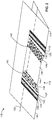
- FIG. 1 is a top perspective view of a wing 110 implemented with an example control surface 112 described herein.
- the control surface 112 includes a flexible portion 114, an inboard articulating seal 116, an outboard articulating seal 118, a first inboard cap 120, and a first outboard cap 122.
- the wing 110 includes an airfoil surface 124, a second inboard cap 126, a second outboard cap 128, and a hinge line 130 (hidden in FIG. 1 and denoted by a dashed line).
- the hinge line 130 is a rod extending through the wing 110 about which the control surface 112 rotates.
- the wing 110 also includes a first actuator, a second actuator, and a third actuator (not shown in FIG. 1 ).
- the first, second, and third actuators are disposed inside the wing 110.
- the flexible portion 114 includes a first rigid region 132, a second rigid region 134, a third rigid region 136, a first flexible region 138, and a second flexible region 140.
- the first outboard cap 122 is attached (e.g., adhered, glued, engaged to, fastened to, cemented to, etc.) to the first rigid region 132.
- the first inboard cap 120 is attached to the third rigid region 136.
- the first rigid region 132 is connected to the first actuator.
- the second rigid region 134 is connected to the second actuator.
- the third rigid region 136 is connected to the third actuator.
- the first flexible region 138 and the second flexible region 140 are defined by perforations 142 in the flexible portion 114.
- the perforations 142 are filled with an elastomer and will be described in greater detail in conjunction with FIGS. 7 , 8 , 9 , and 12 .
- the second rigid region 134 is rotated downwardly relative to the wing 110 about the hinge line 130 by the second actuator while the first rigid region 132 and the first outboard cap 122 are held stationary with respect to the wing 110 by the first actuator.
- the third rigid region 136 and the first inboard cap 120 are held stationary with respect to the wing 110 by the third actuator.
- the first and second flexible regions 138, 140 are flexed to smoothly deflect a trailing edge 144 of the wing 110 downward.
- the first and second flexible regions 138, 140 provide smooth transitions between the first, second, and third rigid regions 132, 134, 136.
- FIG. 2 illustrates the example control surface 112 of FIG. 1 flexed upwardly.
- the second rigid region 134 is rotated upwardly relative to the wing 110 about the hinge line 130 (hidden in FIG. 2 and denoted by a dashed line) by the second actuator while the first rigid region 132 and the first outboard cap 122 are held stationary with respect to the wing 110 by the first actuator and the third rigid region 136 and the first inboard cap 120 are held stationary with respect to the wing 110 by the third actuator.
- the first and second flexible regions 138, 140 are flexed to smoothly deflect the trailing edge 144 of the wing 110 upward.
- FIG. 3 illustrates the example control surface of FIG. 1 articulated downwardly.
- the outboard articulating seal 118 includes a first upper seal assembly 312 and a first lower seal assembly 314.
- the first upper seal assembly 312 is rotatably (e.g., articualbly, pivotably, swingably, hingedly, etc.) engaged with the first lower seal assembly 314 about the hinge line 130 (hidden in FIG. 3 and denoted as a dashed line).
- the inboard articulating seal 116 includes a second upper seal assembly 316 and a second lower seal assembly 318.
- the second upper seal assembly 316 is rotatably engaged with the second lower seal assembly 318 about the hinge line 130.
- the first rigid region 132, the first outboard cap 122, and the first lower seal assembly 314 are rotated downwardly about the hinge line 130 by the first actuator relative to the first and second upper seal assemblies 312, 316 and the wing 110.
- the second rigid region 134 is rotated downwardly about the hinge line 130 by the second actuator relative to the first and second upper seal assemblies 312, 316 and the wing 110.
- the third rigid region 136, the first inboard cap 120, and the second lower seal assembly 318 are rotated downwardly about the hinge line 130 by the third actuator relative to the first and second upper seal assemblies 312, 316 and the wing 110.
- first and second lower seal assemblies 314, 318 and the flexible portion 114 are articulated downwardly relative to the first and second upper seal assemblies 312, 316, and the wing 110 about the hinge line 130.
- the articulated control surface 112 forms an abrupt downward change in the airfoil surface 124.
- the first rigid region 132, the first outboard cap 122, and the first lower seal assembly 314 are held stationary in a downward first position 320 by the first actuator and the third rigid region 136, the first inboard cap 120, and the second lower seal assembly 318 are held stationary by the third actuator in the downward first position 320 while the second rigid region 134 is rotated to a further downward second position 322 by the second actuator.
- the first and second flexible regions 138, 140 are flexed.
- a smooth deflection is formed in the trailing edge 144 along the flexible portion 114.
- the second rigid region 134 is rotated to the downward first position 320 by the second actuator such that the first and second flexible regions 138, 140 are not flexed (not shown in FIG. 3 ).
- the first and third rigid regions 132, 136 are rotated to the downward second position 322 while the second rigid region 134 is rotated to the downward first position 320 to flex the first and second flexible regions 138, 140 (not shown in FIG. 3 ).
- FIG. 4 illustrates the example control surface 112 of FIG. 1 articulated upwardly.
- the first rigid region 132 hidden in FIG. 4
- the first outboard cap 122 and the first upper seal assembly 312 are rotated upwardly about the hinge line 130 by the first actuator relative to the first and second lower seal assemblies 314, 318 and the wing 110.
- the second rigid region 134 is rotated upwardly about the hinge line 130 by the second actuator relative to the first and second lower seal assemblies 314, 318 and the wing 110.
- the third rigid region 136 (hidden in FIG.
- the first inboard cap 120, and the second upper seal assembly 316 are rotated upwardly about the hinge line 130 by the third actuator relative to the first and second lower seal assemblies 314, 318 and the wing 110.
- the first and second upper seal assemblies 312, 316 and the flexible portion 114 are articulated upwardly relative to the first and second lower seal assemblies 314, 318, and the wing 110 about the hinge line 130 (hidden in FIG. 4 and denoted as a dashed line).
- the articulated control surface 112 forms an abrupt upward change in the airfoil surface 124.
- the first rigid region 132, the first outboard cap 122, and the first upper seal assembly 312 are held stationary in an upward first position 412 by the first actuator and the third rigid region 136, the first inboard cap 120, and the second upper seal assembly 316 are held stationary in the upward first position 412 by the third actuator while the second rigid region 134 is rotated to a further upward second position 414 by the second actuator.
- the first and second flexible regions 138, 140 are flexed.
- a smooth deflection is formed in the trailing edge 144 along the flexible portion 114.
- the second rigid region 134 is rotated to the upward first position 412 by the second actuator such that the first and second flexible regions 138, 140 are not flexed (not shown in FIG. 4 ).
- the first and third rigid regions 132, 136 are rotated to the upward second position 414 while the second rigid region 134 is rotated to the upward first position 412 to flex the first and second flexible regions 138, 140 (not shown in FIG. 4 ).
- FIG. 5 is a partial exploded view of the example control surface 112 of FIG. 1 .
- the first upper seal assembly 312 of the outboard articulating seal 118 includes a first upper flap 512 and a first upper rib 514.
- the first lower seal assembly 314 of the outboard articulating seal 118 includes a first lower flap 516 and a first lower rib 518.
- the second upper seal assembly 316 of the inboard articulating seal 116 (not pictured in FIG. 5 ) correspondingly includes a second upper flap and a second upper rib (not pictured in FIG. 5 ).
- the second lower seal assembly 318 of the inboard articulating seal (not pictured in FIG. 5 ) correspondingly includes a second lower flap and a second lower rib (not pictured in FIG. 5 ).
- the first outboard cap 122 covers an outboard end 520 of the control surface 112.
- the second outboard cap 128 covers a first face 522 and a portion of the airfoil surface 124 of the wing 110.
- the first upper rib 514 includes a first hinge engagement hole 524.
- the first lower rib 518 includes a second hinge engagement hole 526.
- the first upper seal assembly 312 and the first lower seal assembly 314 rotate relative to one another about the hinge line 130 (depicted as a line in FIG. 5 ) via the first and second hinge engagement holes 524, 526.
- the second upper and lower ribs correspondingly respectively include a third hinge engagement hole and a fourth hinge engagement hole (not pictured in FIG. 5 ).
- the second upper seal assembly 316 and the second lower seal assembly 318 (not pictured in FIG. 5 ) rotate relative to one another about the hinge line 130 via the third and fourth hinge engagement holes.
- first upper flap 512 and the second upper flap selectively sealingly bridge an upper surface 528 of the control surface 112 and an upper portion 530 of the airfoil surface 124.
- first lower flap 516 and the second lower flap selectively sealingly bridge a lower surface 532 of the control surface 112 and a lower portion 534 of the airfoil surface 124.
- FIG. 6 is a bottom view of the example control surface 112 of FIG. 1 articulated downwardly.
- the first upper flap 512 is engaged with the upper portion 530 and the upper surface 528 is rotated away from the upper flap 512.
- the first lower flap 516 is engaged with the lower surface 532 and rotated away from the lower portion 534.
- Articulating the outboard articulating seal 118 forms a first outboard gap 612 between the first lower rib 518 and the second outboard cap 128 and a second outboard gap 614 between the first upper rib 514 and the first outboard cap 122.
- articulating the inboard articulating seal 116 forms a first inboard gap between the second lower rib and the second inboard cap 126 and a second inboard gap between the second upper rib and the first inboard cap 120 (not pictured in FIG. 6 ).
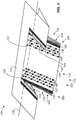
- FIG. 7 is an enlarged perspective cutaway view of the flexible portion 114 of the control surface 112 of FIG. 1 .
- the flexible portion 114 includes a skin 712 and a flexible core 714.
- the flexible core 714 is generally wedge-shaped.
- the skin 712 includes the perforations 142 (e.g., holes, punctures, etc.) filled with an elastomer (e.g., rubber, synthetic rubber, silicone, silicone rubber, fluorosilicone, thermoplastic elastomer, ethylene-vinyl acetate, polyether block amide, chlorosulfonated polyethylene, etc.).
- the perforations 142 are defined by interconnected transverse supports 716 and longitudinal links 718 of the skin 712.
- the perforations 142 are depicted as rounded rectangular openings in FIG. 7 , the perforations 142 may be any shape (e.g., quadrilateral, triangular, hexagonal, circular, polygonal, etc.).
- the skin 712 is adhered (e.g., glued, epoxied, cemented, pasted, etc.) to the flexible core 714. Perforated portions of the skin 712 are bonded to the core 714 using a flexible adhesive (silicone, fluorosilicone, thermoplastic elastomer, polysulfide, flexible epoxy, etc.).
- Unperforated portions of the skin 712 are bonded to the core 714 using a rigid adhesive (epoxy, cynate ester, bismaleimide, polyimide, etc.).
- the first flexible region 138 is formed where the elastomer-filled perforations 142 are adjacent to the flexible core 714.
- the second flexible region 140 is likewise formed by elastomer-filled perforations in the skin 712 adjacent to the flexible core 714 (not pictured in FIG. 7 ).
- the first and second rigid regions 132, 134 are formed where unperforated portions of the skin 712 are adjacent to the flexible core 714.
- the flexible portion 114 is rigid and where portions of the skin 712 including elastomer-filled perforations 142 are adhered to the flexible core 714, the flexible portion 114 is flexible. Additionally or alternatively, the perforated and unperforated portions of the skin 712 may formed from different materials joined via mechanical fasteners and/or adhered together.
- FIG. 8 is an enlarged top view of the flexible portion 114 of FIG. 7 .
- the flexible core 714 is a corrugated structure including corrugations 812 (shown in phantom) defining a matrix of cells 814.
- the flexible core 714 may be formed of any corrugated material (e.g., meta-aramid paper, polyethylene paper, carbon fiber thermoplastic composite, fiberglass fiber thermoplastic composite, metallic foil, carbon fiber thermoset composite, fiberglass thermoset composite, pressboard, etc.).
- any corrugated material e.g., meta-aramid paper, polyethylene paper, carbon fiber thermoplastic composite, fiberglass fiber thermoplastic composite, metallic foil, carbon fiber thermoset composite, fiberglass thermoset composite, pressboard, etc.
- the corrugations 812 may be any shape (e.g., rectilinear, hexagonal, polygonal, rounded, circular, etc.).
- the scallop-shaped corrugations 812 are located adjacent to a portion of the skin 712 including the elastomer-filled perforations 142 and the chevron-shaped corrugations 812 are located adjacent to unperforated portions of the skin 712.
- the corrugations 812 transition from chevron-shaped to scallop-shaped adjacent to where the skin 712 transitions from being unperforated to including elastomer-filled perforations 142 and vice versa. Differing shapes of the corrugations 812, transverse supports 716, longitudinal links 718, and/or perforations 142 may provide differing stiffnesses to the flexible portion 114.
- the materials of the flexible core 714 and of the skin 712 may be shaped (e.g., molded, cut, extruded, perforated, etc.) and bonded to form additional aircraft structures (e.g., the wing 110 of FIG. 1 , fuselages, elevators, rudders, etc.).
- the aircraft structures may include one or more flexible regions (e.g., regions with elastomer-filled perforations in the skin material) to provide a variable internal volume of the aircraft (e.g., to provide additional storage, to change the aerodynamic characteristics of the aircraft, etc.).
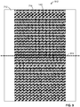
- FIG. 9 is a top view of the skin 712 used to form the flexible portion 114 of FIG. 7 .
- the perforations 142 are arranged in a pattern 912 (e.g., a lattice, a grid, a trellis, a web, etc.) that includes a discontinuity 914 (denoted along a dashed line) along which no transverse supports 716 are present.
- the skin 712 may be bent along the discontinuity 914 when conforming the skin 712 into the airfoil shape of the flexible portion 114, described in greater detail in conjunction with FIGS. 10-11 .
- the skin 712 may be formed of any sheet-type material (e.g., sheet metal, plastic, fiberglass, carbon fiber, plastic, fiber reinforced thermoset composite laminate, fiber reinforced plastic composite laminate, fiber reinforced polyimide composite laminate, etc.).
- the perforations 142 may be cut into the skin 712 and then filled with the elastomer. Thus, the elastomer-filled perforations 142 form a sealed flat spring.
- FIG. 10 is a view of the skin 712 of FIG. 9 conformed to the airfoil shape of the flexible portion 114 of FIG. 7 .
- the skin 712 is bent along the discontinuity 914.
- the discontinuity 914 may aid in conforming the skin 712 to the airfoil shape because less skin 712 material is present along the discontinuity 914. Further, the discontinuity 914 may aid in smoothly deflecting the trailing edge 144 because the longitudinal links 718 along the discontinuity 914 are free to move relative to one another.
- FIG. 11 is an enlarged cutaway view of the flexible portion 114 of FIG. 7 in the upwardly flexed position of FIG. 2 .
- the first outboard cap 122 is adhered to a portion of the first rigid region 132 and the flexible core 714 (hidden in FIG. 12 ) to seal the flexible core 714.
- the transverse supports 716, the longitudinal links 718, the elastomer filling the perforations 142 and the flexible core 714 of the first flexible region 138 bend as the second rigid region 134 is rotated relative to the first rigid region 132.
- FIG. 12 is a cross-sectional view of the control surface 112 and the wing 110 of FIG. 1 .
- the second actuator 1210 and the hinge line 130 described above are visible.
- the wing 110 further includes a closeout structure 1212, a first bracket 1214, and a second bracket 1216.
- the upper portion 530 of the airfoil surface 124 includes an upper hinge cover 1218.
- the lower portion 534 of the airfoil surface 124 includes a lower hinge cover 1220.
- the control surface 112 includes an actuation member 1222.
- the second actuator 1210 includes an arm 1224.
- the second bracket 1216 is attached to the lower portion 534 and supports the hinge line 130.
- the closeout structure 1212 is attached to the upper and lower portions 530, 534 of the airfoil surface 124.
- the first bracket 1214 is attached to the closeout structure 1212.
- the second actuator 1210 is attached to the first bracket 1214.
- the actuation member 1222 is connected to the arm 1224 and rotatably engaged with the hinge line 130.
- the actuation member 1222 is adhered to the skin 712 and to the flexible core 714 to seal (e.g., encapsulate) the flexible core 714.
- the actuation member 1222 includes an interfacing cap to adhere the actuation member 1222 to the flexible core 714 (not shown in FIG. 12 ).
- the skin 712 is slidably engaged with the upper and lower hinge covers 1218, 1220.
- the second actuator 1210 extends and retracts the arm 1224 to rotate the control surface 112 about the hinge line 130.
- the upper and lower hinge covers 1218, 1220 bend and slide on the skin 712 to seal the control surface 112 to the wing 110 as the control surface 112 rotates.
- FIG. 13 is a flowchart of a method 1310 that may be performed to produce the example flexible portion 114 of FIGS. 1 , 2 , 3 , 4 , 5 , 6 , 7 , 8 , 12 , and/or 12.
- the skin 712 is prepared (block 1312).
- a sheet of fiberglass fabric may be saturated with epoxy and cured, a sheet of sheet metal may be unfurled, a sheet of plastic may be extruded, etc.
- the perforations 142 are cut into the skin 712 to form the pattern 912 (block 1316).
- the perforations 142 may be cut by machining, water-jet cutting, die cutting, laser cutting, plasma cutting, etc.
- the perforations 142 may be molded into the skin 712.
- the skin 712 is cleaned (block 1318).
- stray fiberglass threads may be cut, abraded, and/or burned away from the skin 712, burrs may be removed, sharp edges and/or corners may be filed, etc.
- the perforations 142 are filled with the elastomer (block 1320).
- the elastomer may be poured, scooped, spread, injected, molded, etc. into the perforations 142.
- the skin 712 is formed (e.g., bent over a fixture, pressed in a die, rolled, etc.) into an airfoil shape (block 1322).
- the skin 712 is bonded (e.g., adhered, epoxied, glued, etc.) to the flexible core 714 (block 1324).
- a flexible first adhesive bonds the flexible core 714 to perforated portions of the skin 712.
- a rigid second adhesive bonds the flexible core 714 to unperforated (e.g., solid) regions of the skin 712.
- the method 1310 then ends.
- the above disclosed flexible control surfaces and related methods provide control surfaces for aircraft wings that may be deflected to maneuver the aircraft while maintaining smooth (e.g., efficient) airflow over the airfoil surface of the wing. Further, the disclosed flexible control surfaces and related methods provide lightweight and robust structures. Utilizing the disclosed flexible control surfaces and related methods in aircraft manufacture may increase the fuel efficiency and/or range of aircraft. Additionally, the disclosed flexible control surfaces and related methods provide control surfaces that deflect airflow for relatively small flight path adjustments and for large maneuvers. Thus, the number of structures required in an aircraft wing to control the aircraft and associated production and maintenance costs may be reduced.
Landscapes
- Engineering & Computer Science (AREA)
- Aviation & Aerospace Engineering (AREA)
- Mechanical Engineering (AREA)
- Casting Or Compression Moulding Of Plastics Or The Like (AREA)
- Structures Of Non-Positive Displacement Pumps (AREA)
- Turbine Rotor Nozzle Sealing (AREA)
- Toys (AREA)
Abstract
Description
- This disclosure relates generally to aircraft and, more particularly, to flexible control surfaces and related methods.
- Aircraft are typically equipped with control surfaces to maneuver the aircraft during flight. The control surfaces are typically hingedly attached to wings. As the control surfaces are rotated with respect to the wings, air flowing over the wings is deflected and causes the attitude and/or flight path of the aircraft to change. Based on the locations and relative rotation directions of the control surfaces, the aircraft may ascend, descend, roll, and/or turn. Further, deflection of the control surfaces may slow the aircraft, for example, in preparation for landing.
- In one example, an apparatus includes an airfoil including a skin, the skin having perforations filled with an elastomer to increase a flexibility of the skin; and a flexible core adjacent the perforations of the skin to support the skin.
- In another example, an apparatus includes a control surface of an aircraft, the control surface having a flexible core and a flexible skin covering the flexible core, the flexible skin including a plurality of elastomer filled openings to increase a flexibility of the skin.
- In another example, a method includes deflecting a control surface of an aircraft a first amount; maintaining a position of a seal over a gap between the deflected control surface and an airfoil of the aircraft when the control surface is deflected the first amount to maintain a seamless transition between the deflected control surface and the airfoil to reduce pressure leakage across opposing surfaces of the airfoil; and deflecting the control surface a second amount greater than the first amount such that the control surface and the airfoil establish an abrupt transition at the gap between the control surface and the airfoil.
- The following are a series of clauses that disclose features of further aspects of the invention, which may be claimed. The clauses that do not refer to a preceding clause contain essential features of that aspect; the clauses that do refer to one or more preceding clause contain optional features of that aspect.
- 1. An apparatus comprising:
- an airfoil including a skin, the skin having perforations filled with an elastomer to increase a flexibility of the skin; and
- a flexible core adjacent the perforations of the skin to support the skin.
- 2. The apparatus of clause 1, where the perforations are arranged in a lattice pattern.
- 3. The apparatus of
clause 2, wherein the lattice pattern includes a discontinuity of the perforations. - 4. The apparatus of
clause 1 or 2 wherein the skin includes sheet metal, fiberglass plastic, fiber reinforced thermoset composite laminate, fiber reinforced plastic composite laminate, or fiber reinforced polyimide composite laminate. - 5. The apparatus of clause 1,
clause 2, or clause 4 wherein the flexible core is a corrugated structure. - 6. The apparatus of clause 1,
clause 2, clause 4 or clause 5 wherein the skin includes a first portion including the perforations and a second portion adjacent the first portion, the second portion not including the perforations so that that the second portion is less flexible than the first portion. - 7. The apparatus of clause 6 further including an articulating seal to extend over a gap between the second portion and a third portion of the skin adjacent the second portion.
- 8. The apparatus of
clause 7 wherein the articulating seal includes first and second seals on opposing sides of the airfoil, the seals fixed to respective first and second ribs, the first rib to rotate in a first direction while the second rib remains stationary to hold the second seal over a first side of the gap, the second rib to rotate in a second direction away from the first direction while the first rib remains stationary to hold the first seal over a second side of the gap opposite the first side of the gap. - 9. An apparatus comprising:
- a control surface of an aircraft, the control surface having a flexible core and a flexible skin covering the flexible core, the flexible skin including a plurality of elastomer filled openings to increase a flexibility of the skin.
- 10. The apparatus of clause 9 wherein the control surface further includes first and second rigid regions, a flexible transition region coupled between the first and second rigid regions to enable deflection of the second rigid region relative to the first rigid region, the flexible transition region being formed by the flexible skin having the plurality of elastomer filled openings.
- 11. The apparatus of clause 10, wherein the flexible transition region forms a seamless transition between the first and second rigid regions.
- 12. The apparatus of any of clauses 9 to 11, wherein the elastomer filled openings form a grid pattern.
- 13. The apparatus of
clause 12, wherein the grid pattern includes a discontinuity. - 14. The apparatus of any of clauses 9 to 13, wherein the flexible core includes a matrix of cells.
- 15. The apparatus of any of clauses 9 to 14, further including an articulating seal to extend over a gap between the control surface and a wing portion of the aircraft adjacent the control surface.
- 16. The apparatus of clause 15, wherein the articulating seal includes first and second seals on opposing sides of the control surface, the seals fixed to respective first and second ribs, the first rib to rotate in a first direction while the second rib remains stationary to hold the second seal over a first side of the gap, the second rib to rotate in a second direction away from the first direction while the first rib remains stationary to hold the first seal over a second side of the gap opposite the first side of the gap.
- 17. A method comprising:
- deflecting a control surface of an aircraft a first amount;
- maintaining a position of a seal over a gap between the deflected control surface and an airfoil of the aircraft when the control surface is deflected the first amount to maintain a seamless transition between the deflected control surface and the airfoil to reduce pressure leakage across opposing surfaces of the airfoil; and
- deflecting the control surface a second amount greater than the first amount such that the control surface and the airfoil establish an abrupt transition at the gap between the control surface and the airfoil.
- 18. The method of clause 17, wherein the seal articulates when the control surface is deflected the second amount.
- 19. The method of clause 17 or 18 wherein an actuator retains a portion of the control surface when the control surface deflects the first amount and further including releasing a portion of the seal with the actuator to permit deflection of the control surface by the second amount.
- 20. The method of any of clauses 17 to 19 wherein a first rigid region of the control surface deflects relative to a second rigid region of the control surface via a flexible transition region when the control surface deflects the first amount.
-
-
FIG. 1 is a top perspective view of a wing implemented with an example control surface of described herein. -
FIG. 2 illustrates the example control surface ofFIG. 1 flexed upwardly. -
FIG. 3 illustrates the example control surface ofFIG. 1 articulated downwardly. -
FIG. 4 illustrates the example control surface ofFIG. 1 articulated upwardly. -
FIG. 5 is a partial exploded view of the example control surface ofFIG. 1 . -
FIG. 6 is a bottom view of the example control surface ofFIG. 1 articulated downwardly. -
FIG. 7 is an enlarged cutaway perspective view of a flexible portion of the control surface ofFIG. 1 . -
FIG. 8 is an enlarged top view of the flexible portion ofFIG. 7 . -
FIG. 9 is a top view of the skin used to form the flexible portion ofFIG. 7 . -
FIG. 10 is a view of the skin ofFIG. 9 conformed to the airfoil shape of the flexible portion ofFIG. 7 . -
FIG. 11 is an enlarged cutaway view of the flexible portion ofFIG. 7 in the upwardly flexed position ofFIG. 2 . -
FIG. 12 is a cross-sectional view of the control surface and the wing ofFIG. 1 . -
FIG. 13 is a flowchart of a method that may be performed to produce the example flexible portion ofFIGS. 1 ,2 ,3 ,4 ,5 ,6 ,7 ,8 ,12 , and/or 13. - The figures are not to scale. Instead, to clarify multiple layers and regions, the thickness of the layers may be enlarged in the drawings. Wherever possible, the same reference numbers will be used throughout the drawing(s) and accompanying written description to refer to the same or like parts. As used in this patent, stating that any part (e.g., a layer, film, area, or plate) is in any way positioned on (e.g., positioned on, located on, disposed on, or formed on, etc.) another part, means that the referenced part is either in contact with the other part, or that the referenced part is above the other part with one or more intermediate part(s) located therebetween. Stating that any part is in contact with another part means that there is no intermediate part between the two parts.
- In general, the example flexible control surfaces described herein may be used with aircraft wings to provide improved aerodynamics over the wings. The example flexible control surfaces described herein provide significantly increased efficiency of air movement over the wings of aircraft (e.g., reduce drag) during maneuvering and in-flight aircraft attitude adjustments. Further, the example flexible control surfaces described herein include fewer and lighter components than some known control surfaces. Thus, the example flexible control surfaces described herein provide significantly increased fuel efficiency and/or range to aircraft.
- Example flexible control surfaces described herein are composed of a flexible portion and opposing rotatable seals. Unlike the above-mentioned known control surfaces, the flexible control surfaces described herein flex (e.g., bend, deflect, twist, warp, etc.) to provide a continuous substantially smooth geometrically variable wing surface to achieve relatively small aircraft maneuvers. Additionally, the flexible control surfaces articulate (e.g., rotate relative to the wing) to provide a discontinuous wing surface to achieve relatively large aircraft maneuvers. More specifically, the flexible portion includes a corrugated core adhered to a partially perforated skin to produce rigid and flexible regions of the flexible portion. The opposing rotatable seals are engaged with inboard and outboard ends of the flexible portion. By rotating the rigid regions of the flexible portion relative to one another to flex the flexible regions and sealing the inboard and outboard ends of the flexible portion with adjacent portions of an aircraft wing, the overall shape and, thus, aerodynamics of the wing are changed without creating abrupt changes in the surface of the wing. As a result, air is smoothly deflected over the wing to maneuver the aircraft with minimized drag when making relatively small aircraft attitude and/or flight path adjustments. Further, by rotating or articulating the flexible portion and releasing the opposing seals at the inboard and outboard ends of the flexible portion, abrupt changes are produced in the surface of the wing. As a result, air is turbulently deflected over the wing to slow the aircraft and/or make sudden and/or relatively large maneuvers. Therefore, the flexible control surfaces described herein can provide both smooth (e.g., continuous) and abrupt changes to wing geometry.
-
FIG. 1 is a top perspective view of awing 110 implemented with anexample control surface 112 described herein. In the illustrated example ofFIG. 1 , thecontrol surface 112 includes aflexible portion 114, aninboard articulating seal 116, anoutboard articulating seal 118, a firstinboard cap 120, and a firstoutboard cap 122. Thewing 110 includes anairfoil surface 124, a secondinboard cap 126, a secondoutboard cap 128, and a hinge line 130 (hidden inFIG. 1 and denoted by a dashed line). Thehinge line 130 is a rod extending through thewing 110 about which thecontrol surface 112 rotates. Thewing 110 also includes a first actuator, a second actuator, and a third actuator (not shown inFIG. 1 ). The first, second, and third actuators are disposed inside thewing 110. Theflexible portion 114 includes a firstrigid region 132, a secondrigid region 134, a thirdrigid region 136, a firstflexible region 138, and a secondflexible region 140. The firstoutboard cap 122 is attached (e.g., adhered, glued, engaged to, fastened to, cemented to, etc.) to the firstrigid region 132. The firstinboard cap 120 is attached to the thirdrigid region 136. The firstrigid region 132 is connected to the first actuator. The secondrigid region 134 is connected to the second actuator. The thirdrigid region 136 is connected to the third actuator. The firstflexible region 138 and the secondflexible region 140 are defined byperforations 142 in theflexible portion 114. Theperforations 142 are filled with an elastomer and will be described in greater detail in conjunction withFIGS. 7 ,8 ,9 , and12 . - In the illustrated example of
FIG. 1 , the secondrigid region 134 is rotated downwardly relative to thewing 110 about thehinge line 130 by the second actuator while the firstrigid region 132 and the firstoutboard cap 122 are held stationary with respect to thewing 110 by the first actuator. Also, the thirdrigid region 136 and the firstinboard cap 120 are held stationary with respect to thewing 110 by the third actuator. Thus, the first and secondflexible regions edge 144 of thewing 110 downward. Thus, the first and secondflexible regions rigid regions -
FIG. 2 illustrates theexample control surface 112 ofFIG. 1 flexed upwardly. In the illustrated example ofFIG. 2 , the secondrigid region 134 is rotated upwardly relative to thewing 110 about the hinge line 130 (hidden inFIG. 2 and denoted by a dashed line) by the second actuator while the firstrigid region 132 and the firstoutboard cap 122 are held stationary with respect to thewing 110 by the first actuator and the thirdrigid region 136 and the firstinboard cap 120 are held stationary with respect to thewing 110 by the third actuator. Thus, the first and secondflexible regions edge 144 of thewing 110 upward. -
FIG. 3 illustrates the example control surface ofFIG. 1 articulated downwardly. As shown inFIG. 3 , theoutboard articulating seal 118 includes a firstupper seal assembly 312 and a firstlower seal assembly 314. The firstupper seal assembly 312 is rotatably (e.g., articualbly, pivotably, swingably, hingedly, etc.) engaged with the firstlower seal assembly 314 about the hinge line 130 (hidden inFIG. 3 and denoted as a dashed line). As shown inFIG. 3 , theinboard articulating seal 116 includes a secondupper seal assembly 316 and a secondlower seal assembly 318. The secondupper seal assembly 316 is rotatably engaged with the secondlower seal assembly 318 about thehinge line 130. - In the illustrated example of
FIG. 3 , the firstrigid region 132, the firstoutboard cap 122, and the firstlower seal assembly 314 are rotated downwardly about thehinge line 130 by the first actuator relative to the first and secondupper seal assemblies wing 110. In the illustrated example ofFIG. 3 , the secondrigid region 134 is rotated downwardly about thehinge line 130 by the second actuator relative to the first and secondupper seal assemblies wing 110. In the illustrated example ofFIG. 3 , the thirdrigid region 136, the firstinboard cap 120, and the secondlower seal assembly 318 are rotated downwardly about thehinge line 130 by the third actuator relative to the first and secondupper seal assemblies wing 110. Thus, the first and secondlower seal assemblies flexible portion 114 are articulated downwardly relative to the first and secondupper seal assemblies wing 110 about thehinge line 130. Thus, the articulatedcontrol surface 112 forms an abrupt downward change in theairfoil surface 124. - In the illustrated example of
FIG. 3 , the firstrigid region 132, the firstoutboard cap 122, and the firstlower seal assembly 314 are held stationary in a downwardfirst position 320 by the first actuator and the thirdrigid region 136, the firstinboard cap 120, and the secondlower seal assembly 318 are held stationary by the third actuator in the downwardfirst position 320 while the secondrigid region 134 is rotated to a further downwardsecond position 322 by the second actuator. Thus, the first and secondflexible regions FIG. 3 , while thecontrol surface 112 is articulated downwardly relative to thewing 110, a smooth deflection is formed in the trailingedge 144 along theflexible portion 114. In some examples, the secondrigid region 134 is rotated to the downwardfirst position 320 by the second actuator such that the first and secondflexible regions FIG. 3 ). In some examples, the first and thirdrigid regions second position 322 while the secondrigid region 134 is rotated to the downwardfirst position 320 to flex the first and secondflexible regions 138, 140 (not shown inFIG. 3 ). -
FIG. 4 illustrates theexample control surface 112 ofFIG. 1 articulated upwardly. In the illustrated example ofFIG. 4 , the first rigid region 132 (hidden inFIG. 4 ), the firstoutboard cap 122, and the firstupper seal assembly 312 are rotated upwardly about thehinge line 130 by the first actuator relative to the first and secondlower seal assemblies wing 110. In the illustrated example ofFIG. 3 , the secondrigid region 134 is rotated upwardly about thehinge line 130 by the second actuator relative to the first and secondlower seal assemblies wing 110. In the illustrated example ofFIG. 3 , the third rigid region 136 (hidden inFIG. 4 ), the firstinboard cap 120, and the secondupper seal assembly 316 are rotated upwardly about thehinge line 130 by the third actuator relative to the first and secondlower seal assemblies wing 110. Thus, the first and secondupper seal assemblies flexible portion 114 are articulated upwardly relative to the first and secondlower seal assemblies wing 110 about the hinge line 130 (hidden inFIG. 4 and denoted as a dashed line). Thus, the articulatedcontrol surface 112 forms an abrupt upward change in theairfoil surface 124. - In the illustrated example of
FIG. 4 , the firstrigid region 132, the firstoutboard cap 122, and the firstupper seal assembly 312 are held stationary in an upwardfirst position 412 by the first actuator and the thirdrigid region 136, the firstinboard cap 120, and the secondupper seal assembly 316 are held stationary in the upwardfirst position 412 by the third actuator while the secondrigid region 134 is rotated to a further upwardsecond position 414 by the second actuator. Thus, the first and secondflexible regions control surface 112 is articulated upwardly relative to thewing 110, a smooth deflection is formed in the trailingedge 144 along theflexible portion 114. In some examples, the secondrigid region 134 is rotated to the upwardfirst position 412 by the second actuator such that the first and secondflexible regions FIG. 4 ). In some examples, the first and thirdrigid regions second position 414 while the secondrigid region 134 is rotated to the upwardfirst position 412 to flex the first and secondflexible regions 138, 140 (not shown inFIG. 4 ). -
FIG. 5 is a partial exploded view of theexample control surface 112 ofFIG. 1 . In the illustrated example ofFIG. 5 , the firstupper seal assembly 312 of theoutboard articulating seal 118 includes a firstupper flap 512 and a firstupper rib 514. The firstlower seal assembly 314 of theoutboard articulating seal 118 includes a firstlower flap 516 and a firstlower rib 518. - The second
upper seal assembly 316 of the inboard articulating seal 116 (not pictured inFIG. 5 ) correspondingly includes a second upper flap and a second upper rib (not pictured inFIG. 5 ). The secondlower seal assembly 318 of the inboard articulating seal (not pictured inFIG. 5 ) correspondingly includes a second lower flap and a second lower rib (not pictured inFIG. 5 ). - The first
outboard cap 122 covers anoutboard end 520 of thecontrol surface 112. The secondoutboard cap 128 covers afirst face 522 and a portion of theairfoil surface 124 of thewing 110. The firstupper rib 514 includes a firsthinge engagement hole 524. The firstlower rib 518 includes a secondhinge engagement hole 526. The firstupper seal assembly 312 and the firstlower seal assembly 314 rotate relative to one another about the hinge line 130 (depicted as a line inFIG. 5 ) via the first and second hinge engagement holes 524, 526. - The second upper and lower ribs correspondingly respectively include a third hinge engagement hole and a fourth hinge engagement hole (not pictured in
FIG. 5 ). The secondupper seal assembly 316 and the second lower seal assembly 318 (not pictured inFIG. 5 ) rotate relative to one another about thehinge line 130 via the third and fourth hinge engagement holes. - In operation, the first
upper flap 512 and the second upper flap selectively sealingly bridge anupper surface 528 of thecontrol surface 112 and anupper portion 530 of theairfoil surface 124. In operation, the firstlower flap 516 and the second lower flap selectively sealingly bridge alower surface 532 of thecontrol surface 112 and alower portion 534 of theairfoil surface 124. -
FIG. 6 is a bottom view of theexample control surface 112 ofFIG. 1 articulated downwardly. In the illustrated example ofFIG. 6 , the firstupper flap 512 is engaged with theupper portion 530 and theupper surface 528 is rotated away from theupper flap 512. The firstlower flap 516 is engaged with thelower surface 532 and rotated away from thelower portion 534. Articulating theoutboard articulating seal 118 forms a firstoutboard gap 612 between the firstlower rib 518 and the secondoutboard cap 128 and a secondoutboard gap 614 between the firstupper rib 514 and the firstoutboard cap 122. - Correspondingly, articulating the
inboard articulating seal 116 forms a first inboard gap between the second lower rib and the secondinboard cap 126 and a second inboard gap between the second upper rib and the first inboard cap 120 (not pictured inFIG. 6 ). -
FIG. 7 is an enlarged perspective cutaway view of theflexible portion 114 of thecontrol surface 112 ofFIG. 1 . In the illustrated example ofFIG. 7 , theflexible portion 114 includes askin 712 and aflexible core 714. Theflexible core 714 is generally wedge-shaped. Theskin 712 includes the perforations 142 (e.g., holes, punctures, etc.) filled with an elastomer (e.g., rubber, synthetic rubber, silicone, silicone rubber, fluorosilicone, thermoplastic elastomer, ethylene-vinyl acetate, polyether block amide, chlorosulfonated polyethylene, etc.). Theperforations 142 are defined by interconnectedtransverse supports 716 andlongitudinal links 718 of theskin 712. Although theperforations 142 are depicted as rounded rectangular openings inFIG. 7 , theperforations 142 may be any shape (e.g., quadrilateral, triangular, hexagonal, circular, polygonal, etc.). Theskin 712 is adhered (e.g., glued, epoxied, cemented, pasted, etc.) to theflexible core 714. Perforated portions of theskin 712 are bonded to thecore 714 using a flexible adhesive (silicone, fluorosilicone, thermoplastic elastomer, polysulfide, flexible epoxy, etc.). Unperforated portions of theskin 712 are bonded to thecore 714 using a rigid adhesive (epoxy, cynate ester, bismaleimide, polyimide, etc.). The firstflexible region 138 is formed where the elastomer-filledperforations 142 are adjacent to theflexible core 714. The secondflexible region 140 is likewise formed by elastomer-filled perforations in theskin 712 adjacent to the flexible core 714 (not pictured inFIG. 7 ). The first and secondrigid regions skin 712 are adjacent to theflexible core 714. In other words, where unperforated portions of theskin 712 are adhered to theflexible core 714, theflexible portion 114 is rigid and where portions of theskin 712 including elastomer-filledperforations 142 are adhered to theflexible core 714, theflexible portion 114 is flexible. Additionally or alternatively, the perforated and unperforated portions of theskin 712 may formed from different materials joined via mechanical fasteners and/or adhered together. -
FIG. 8 is an enlarged top view of theflexible portion 114 ofFIG. 7 . In the illustrated example ofFIG. 8 , theflexible core 714 is a corrugated structure including corrugations 812 (shown in phantom) defining a matrix ofcells 814. Theflexible core 714 may be formed of any corrugated material (e.g., meta-aramid paper, polyethylene paper, carbon fiber thermoplastic composite, fiberglass fiber thermoplastic composite, metallic foil, carbon fiber thermoset composite, fiberglass thermoset composite, pressboard, etc.). In the illustrated example ofFIG. 8 , although thecorrugations 812 are depicted as chevron-shaped and as scallop-shaped, thecorrugations 812 maybe any shape (e.g., rectilinear, hexagonal, polygonal, rounded, circular, etc.). In the illustrated example ofFIG. 8 , the scallop-shapedcorrugations 812 are located adjacent to a portion of theskin 712 including the elastomer-filledperforations 142 and the chevron-shapedcorrugations 812 are located adjacent to unperforated portions of theskin 712. Thecorrugations 812 transition from chevron-shaped to scallop-shaped adjacent to where theskin 712 transitions from being unperforated to including elastomer-filledperforations 142 and vice versa. Differing shapes of thecorrugations 812,transverse supports 716,longitudinal links 718, and/orperforations 142 may provide differing stiffnesses to theflexible portion 114. - Additionally or alternatively, the materials of the
flexible core 714 and of theskin 712 may be shaped (e.g., molded, cut, extruded, perforated, etc.) and bonded to form additional aircraft structures (e.g., thewing 110 ofFIG. 1 , fuselages, elevators, rudders, etc.). In some such examples, the aircraft structures may include one or more flexible regions (e.g., regions with elastomer-filled perforations in the skin material) to provide a variable internal volume of the aircraft (e.g., to provide additional storage, to change the aerodynamic characteristics of the aircraft, etc.). -
FIG. 9 is a top view of theskin 712 used to form theflexible portion 114 ofFIG. 7 . In the illustrated example ofFIG. 9 , theperforations 142 are arranged in a pattern 912 (e.g., a lattice, a grid, a trellis, a web, etc.) that includes a discontinuity 914 (denoted along a dashed line) along which no transverse supports 716 are present. Theskin 712 may be bent along thediscontinuity 914 when conforming theskin 712 into the airfoil shape of theflexible portion 114, described in greater detail in conjunction withFIGS. 10-11 . Theskin 712 may be formed of any sheet-type material (e.g., sheet metal, plastic, fiberglass, carbon fiber, plastic, fiber reinforced thermoset composite laminate, fiber reinforced plastic composite laminate, fiber reinforced polyimide composite laminate, etc.). Theperforations 142 may be cut into theskin 712 and then filled with the elastomer. Thus, the elastomer-filledperforations 142 form a sealed flat spring. -
FIG. 10 is a view of theskin 712 ofFIG. 9 conformed to the airfoil shape of theflexible portion 114 ofFIG. 7 . In the illustrated example ofFIG. 10 , theskin 712 is bent along thediscontinuity 914. Thediscontinuity 914 may aid in conforming theskin 712 to the airfoil shape becauseless skin 712 material is present along thediscontinuity 914. Further, thediscontinuity 914 may aid in smoothly deflecting the trailingedge 144 because thelongitudinal links 718 along thediscontinuity 914 are free to move relative to one another. -
FIG. 11 is an enlarged cutaway view of theflexible portion 114 ofFIG. 7 in the upwardly flexed position ofFIG. 2 . In the illustrated example ofFIG. 12 , the firstoutboard cap 122 is adhered to a portion of the firstrigid region 132 and the flexible core 714 (hidden inFIG. 12 ) to seal theflexible core 714. In operation, the transverse supports 716, thelongitudinal links 718, the elastomer filling theperforations 142 and theflexible core 714 of the firstflexible region 138 bend as the secondrigid region 134 is rotated relative to the firstrigid region 132. -
FIG. 12 is a cross-sectional view of thecontrol surface 112 and thewing 110 ofFIG. 1 . In the illustrated example, thesecond actuator 1210 and thehinge line 130 described above are visible. In the illustrated example, thewing 110 further includes acloseout structure 1212, afirst bracket 1214, and asecond bracket 1216. Theupper portion 530 of theairfoil surface 124 includes anupper hinge cover 1218. Thelower portion 534 of theairfoil surface 124 includes alower hinge cover 1220. Thecontrol surface 112 includes anactuation member 1222. Thesecond actuator 1210 includes anarm 1224. Thesecond bracket 1216 is attached to thelower portion 534 and supports thehinge line 130. Thecloseout structure 1212 is attached to the upper andlower portions airfoil surface 124. Thefirst bracket 1214 is attached to thecloseout structure 1212. Thesecond actuator 1210 is attached to thefirst bracket 1214. Theactuation member 1222 is connected to thearm 1224 and rotatably engaged with thehinge line 130. Theactuation member 1222 is adhered to theskin 712 and to theflexible core 714 to seal (e.g., encapsulate) theflexible core 714. In some examples, theactuation member 1222 includes an interfacing cap to adhere theactuation member 1222 to the flexible core 714 (not shown inFIG. 12 ). Theskin 712 is slidably engaged with the upper and lower hinge covers 1218, 1220. - In operation, the
second actuator 1210 extends and retracts thearm 1224 to rotate thecontrol surface 112 about thehinge line 130. The upper and lower hinge covers 1218, 1220 bend and slide on theskin 712 to seal thecontrol surface 112 to thewing 110 as thecontrol surface 112 rotates. -
FIG. 13 is a flowchart of amethod 1310 that may be performed to produce the exampleflexible portion 114 ofFIGS. 1 ,2 ,3 ,4 ,5 ,6 ,7 ,8 ,12 , and/or 12. Initially, theskin 712 is prepared (block 1312). For example, atblock 1312, a sheet of fiberglass fabric may be saturated with epoxy and cured, a sheet of sheet metal may be unfurled, a sheet of plastic may be extruded, etc. Then, theperforations 142 are cut into theskin 712 to form the pattern 912 (block 1316). For example, atblock 1316, theperforations 142 may be cut by machining, water-jet cutting, die cutting, laser cutting, plasma cutting, etc. Additionally, or alternatively, atblock 1316, theperforations 142 may be molded into theskin 712. Next, theskin 712 is cleaned (block 1318). For example, atblock 1318, stray fiberglass threads may be cut, abraded, and/or burned away from theskin 712, burrs may be removed, sharp edges and/or corners may be filed, etc. Further, theperforations 142 are filled with the elastomer (block 1320). For example, atblock 1320, the elastomer may be poured, scooped, spread, injected, molded, etc. into theperforations 142. Then, theskin 712 is formed (e.g., bent over a fixture, pressed in a die, rolled, etc.) into an airfoil shape (block 1322). Next, theskin 712 is bonded (e.g., adhered, epoxied, glued, etc.) to the flexible core 714 (block 1324). In some examples, a flexible first adhesive bonds theflexible core 714 to perforated portions of theskin 712. In some examples, a rigid second adhesive bonds theflexible core 714 to unperforated (e.g., solid) regions of theskin 712. Themethod 1310 then ends. - From the foregoing, it will be appreciated that the above disclosed flexible control surfaces and related methods provide control surfaces for aircraft wings that may be deflected to maneuver the aircraft while maintaining smooth (e.g., efficient) airflow over the airfoil surface of the wing. Further, the disclosed flexible control surfaces and related methods provide lightweight and robust structures. Utilizing the disclosed flexible control surfaces and related methods in aircraft manufacture may increase the fuel efficiency and/or range of aircraft. Additionally, the disclosed flexible control surfaces and related methods provide control surfaces that deflect airflow for relatively small flight path adjustments and for large maneuvers. Thus, the number of structures required in an aircraft wing to control the aircraft and associated production and maintenance costs may be reduced.
- Although certain example methods, apparatus and articles of manufacture have been disclosed herein, the scope of coverage of this patent is not limited thereto. On the contrary, this patent covers all methods, apparatus and articles of manufacture fairly falling within the scope of the claims of this patent.
Claims (12)
- An apparatus comprising:an airfoil including a skin, the skin having perforations filled with an elastomer to increase a flexibility of the skin; anda flexible core adjacent the perforations of the skin to support the skin.
- The apparatus of claim 1, where the perforations are arranged in a lattice pattern.
- The apparatus of claim 2, wherein the lattice pattern includes a discontinuity of the perforations.
- The apparatus of claim 1 or claim 2 wherein the skin includes sheet metal, fiberglass plastic, fiber reinforced thermoset composite laminate, fiber reinforced plastic composite laminate, or fiber reinforced polyimide composite laminate.
- The apparatus of claim 1, claim 2, or claim 4 wherein the flexible core is a corrugated structure.
- The apparatus of claim 1, claim 2, claim 4 or claim 5 wherein the skin includes a first portion including the perforations and a second portion adjacent the first portion, the second portion not including the perforations so that that the second portion is less flexible than the first portion.
- The apparatus of claim 6 further including an articulating seal to extend over a gap between the second portion and a third portion of the skin adjacent the second portion.
- The apparatus of claim 7 wherein the articulating seal includes first and second seals on opposing sides of the airfoil, the seals fixed to respective first and second ribs, the first rib to rotate in a first direction while the second rib remains stationary to hold the second seal over a first side of the gap, the second rib to rotate in a second direction away from the first direction while the first rib remains stationary to hold the first seal over a second side of the gap opposite the first side of the gap.
- A method comprising:deflecting a control surface of an aircraft a first amount;maintaining a position of a seal over a gap between the deflected control surface and an airfoil of the aircraft when the control surface is deflected the first amount to maintain a seamless transition between the deflected control surface and the airfoil to reduce pressure leakage across opposing surfaces of the airfoil; anddeflecting the control surface a second amount greater than the first amount such that the control surface and the airfoil establish an abrupt transition at the gap between the control surface and the airfoil.
- The method of claim 9, wherein the seal articulates when the control surface is deflected the second amount.
- The method of claim 9 or 10 wherein an actuator retains a portion of the control surface when the control surface deflects the first amount and further including releasing a portion of the seal with the actuator to permit deflection of the control surface by the second amount.
- The method of any of claims 9 to 11 wherein a first rigid region of the control surface deflects relative to a second rigid region of the control surface via a flexible transition region when the control surface deflects the first amount.
Applications Claiming Priority (1)
| Application Number | Priority Date | Filing Date | Title |
|---|---|---|---|
| US15/452,993 US10549838B2 (en) | 2017-03-08 | 2017-03-08 | Flexible control surfaces and related methods |
Publications (2)
| Publication Number | Publication Date |
|---|---|
| EP3372490A1 true EP3372490A1 (en) | 2018-09-12 |
| EP3372490B1 EP3372490B1 (en) | 2021-05-05 |
Family
ID=61581022
Family Applications (1)
| Application Number | Title | Priority Date | Filing Date |
|---|---|---|---|
| EP18160272.3A Active EP3372490B1 (en) | 2017-03-08 | 2018-03-06 | Flexible control surfaces and related methods |
Country Status (3)
| Country | Link |
|---|---|
| US (1) | US10549838B2 (en) |
| EP (1) | EP3372490B1 (en) |
| CN (1) | CN108569389B (en) |
Cited By (1)
| Publication number | Priority date | Publication date | Assignee | Title |
|---|---|---|---|---|
| WO2023037120A1 (en) * | 2021-09-13 | 2023-03-16 | Mbda Uk Limited | Foldable moveable member for an air vehicle |
Families Citing this family (6)
| Publication number | Priority date | Publication date | Assignee | Title |
|---|---|---|---|---|
| GB201615399D0 (en) * | 2016-09-09 | 2016-10-26 | Univ Brunel | Blade or wing |
| US10843788B2 (en) * | 2017-06-29 | 2020-11-24 | Textron Innovations Inc. | Damping structures for tiltrotor aircraft wings |
| US11046415B1 (en) * | 2018-06-20 | 2021-06-29 | United States of Americas as represented by the Secretary of the Air Force | Multi-material printed control surface |
| US11691357B2 (en) | 2020-02-03 | 2023-07-04 | Rohr, Inc. | Thermoplastic composite panel systems and methods |
| CN112455651B (en) * | 2020-11-02 | 2022-05-03 | 哈尔滨工业大学 | Flexible bionic wing folding and unfolding mechanism based on lead screw transmission self-locking scheme |
| CN114291249B (en) * | 2021-12-31 | 2023-08-04 | 中国飞机强度研究所 | Variable-thickness wing structure |
Citations (9)
| Publication number | Priority date | Publication date | Assignee | Title |
|---|---|---|---|---|
| US5518210A (en) * | 1994-04-11 | 1996-05-21 | Mcdonnell Douglas Corporation | Seal plate for aircraft movable flight control surfaces |
| US6145791A (en) * | 1998-01-09 | 2000-11-14 | Northrop Grumman Corporation | Elastomeric transition for aircraft control surface |
| US6173924B1 (en) * | 1999-06-15 | 2001-01-16 | Northrop Grumman Corporation | Low density flexible edge transition |
| US6209824B1 (en) * | 1997-09-17 | 2001-04-03 | The Boeing Company | Control surface for an aircraft |
| US20050151015A1 (en) * | 2003-04-09 | 2005-07-14 | United States Of America As Represented By The Administrator Of The Nasa | Adaptive composite skin technology (ACTS) |
| US20060163431A1 (en) * | 2004-11-24 | 2006-07-27 | Airbus Deutschland Gmbh | Cover skin for a variable-shape aerodynamic area |
| EP2397403A2 (en) * | 2010-06-15 | 2011-12-21 | The Boeing Company | Morphing control surface transition |
| US20130064666A1 (en) * | 2008-07-29 | 2013-03-14 | The Government Of The Us, As Represented By The Secretary Of The Navy | Active twist hollow beam system |
| EP2987628A1 (en) * | 2014-08-15 | 2016-02-24 | The Boeing Company | Conductive thermoplastic ground plane for use in an aircraft |
Family Cites Families (21)
| Publication number | Priority date | Publication date | Assignee | Title |
|---|---|---|---|---|
| US3991245A (en) | 1974-09-18 | 1976-11-09 | Hexcel Corporation | Flexible honeycomb structure |
| US5222699A (en) | 1990-04-16 | 1993-06-29 | Ltv Aerospace And Defense Company | Variable control aircraft control surface |
| US5431980A (en) | 1993-02-01 | 1995-07-11 | Mccarthy; Daniel J. | Formable cellular material with synclastic behavior |
| US5662294A (en) * | 1994-02-28 | 1997-09-02 | Lockheed Martin Corporation | Adaptive control surface using antagonistic shape memory alloy tendons |
| US5794893A (en) | 1995-06-07 | 1998-08-18 | Northrop Grumman Corporation | Elastomeric transition for aircraft control surface |
| US5803405A (en) | 1995-06-07 | 1998-09-08 | Northrop Grumman Corporation | Expandable aircraft section |
| US5810291A (en) | 1996-03-19 | 1998-09-22 | Geiger; Michael Watson | Continuous moldline technology system |
| US6027074A (en) | 1997-02-27 | 2000-02-22 | Mcdonnell Douglas | Reinforced elastomer panel |
| US5941480A (en) | 1997-05-08 | 1999-08-24 | Mcdonnell Douglas | Hinge line skin system for an aircraft |
| US5927651A (en) | 1997-05-15 | 1999-07-27 | Mcdonnell Douglas | Expandable fuel cell |
| US5931422A (en) | 1997-06-09 | 1999-08-03 | Mcdonnell Douglas | Active reinforced elastomer system |
| US5887828A (en) * | 1997-11-13 | 1999-03-30 | Northrop Grumman Corporation | Seamless mission adaptive control surface |
| US6015115A (en) | 1998-03-25 | 2000-01-18 | Lockheed Martin Corporation | Inflatable structures to control aircraft |
| US6068219A (en) | 1998-04-13 | 2000-05-30 | Northrop Grumman Corporation | Single surface multi axis aircraft control |
| US6173925B1 (en) | 1998-04-16 | 2001-01-16 | Daimlerchrysler Ag | Skin-rib structure |
| US6575407B2 (en) | 2000-10-18 | 2003-06-10 | Lockheed Martin Corporation | Subdermally-reinforced elastomeric transitions |
| DE10317258B4 (en) | 2003-04-14 | 2006-09-07 | Eads Deutschland Gmbh | Adjustment mechanism for a shape-variable wing |
| US20070138341A1 (en) | 2004-12-07 | 2007-06-21 | Joshi Shiv P | Transformable skin |
| DE102005061751B4 (en) * | 2005-12-21 | 2013-09-19 | Eurocopter Deutschland Gmbh | Rotor blade for a rotary wing aircraft |
| US8844879B2 (en) * | 2011-12-12 | 2014-09-30 | The Boeing Company | Wing variable camber trailing edge tip |
| US9975623B2 (en) * | 2016-03-08 | 2018-05-22 | Northrop Grumman Systems Corporation | Elastomeric transition |
-
2017
- 2017-03-08 US US15/452,993 patent/US10549838B2/en active Active
-
2018
- 2018-03-01 CN CN201810170353.4A patent/CN108569389B/en active Active
- 2018-03-06 EP EP18160272.3A patent/EP3372490B1/en active Active
Patent Citations (9)
| Publication number | Priority date | Publication date | Assignee | Title |
|---|---|---|---|---|
| US5518210A (en) * | 1994-04-11 | 1996-05-21 | Mcdonnell Douglas Corporation | Seal plate for aircraft movable flight control surfaces |
| US6209824B1 (en) * | 1997-09-17 | 2001-04-03 | The Boeing Company | Control surface for an aircraft |
| US6145791A (en) * | 1998-01-09 | 2000-11-14 | Northrop Grumman Corporation | Elastomeric transition for aircraft control surface |
| US6173924B1 (en) * | 1999-06-15 | 2001-01-16 | Northrop Grumman Corporation | Low density flexible edge transition |
| US20050151015A1 (en) * | 2003-04-09 | 2005-07-14 | United States Of America As Represented By The Administrator Of The Nasa | Adaptive composite skin technology (ACTS) |
| US20060163431A1 (en) * | 2004-11-24 | 2006-07-27 | Airbus Deutschland Gmbh | Cover skin for a variable-shape aerodynamic area |
| US20130064666A1 (en) * | 2008-07-29 | 2013-03-14 | The Government Of The Us, As Represented By The Secretary Of The Navy | Active twist hollow beam system |
| EP2397403A2 (en) * | 2010-06-15 | 2011-12-21 | The Boeing Company | Morphing control surface transition |
| EP2987628A1 (en) * | 2014-08-15 | 2016-02-24 | The Boeing Company | Conductive thermoplastic ground plane for use in an aircraft |
Cited By (5)
| Publication number | Priority date | Publication date | Assignee | Title |
|---|---|---|---|---|
| WO2023037120A1 (en) * | 2021-09-13 | 2023-03-16 | Mbda Uk Limited | Foldable moveable member for an air vehicle |
| GB2610813A (en) * | 2021-09-13 | 2023-03-22 | Mbda Uk Ltd | Foldable moveable member for an air vehicle |
| GB2610813B (en) * | 2021-09-13 | 2024-02-21 | Mbda Uk Ltd | Foldable moveable member for an air vehicle |
| GB2625666A (en) * | 2021-09-13 | 2024-06-26 | Mbda Uk Ltd | Foldable moveable member for an air vehicle |
| US12601574B2 (en) | 2021-09-13 | 2026-04-14 | Mbda Uk Limited | Foldable moveable member for an air vehicle with fold region having a plurality of holes |
Also Published As
| Publication number | Publication date |
|---|---|
| US20180257759A1 (en) | 2018-09-13 |
| EP3372490B1 (en) | 2021-05-05 |
| CN108569389B (en) | 2023-05-30 |
| CN108569389A (en) | 2018-09-25 |
| US10549838B2 (en) | 2020-02-04 |
Similar Documents
| Publication | Publication Date | Title |
|---|---|---|
| US10549838B2 (en) | Flexible control surfaces and related methods | |
| US7243881B2 (en) | Multi-function trailing edge devices and associated methods | |
| US10654557B2 (en) | Morphing skin for an aircraft | |
| US5222699A (en) | Variable control aircraft control surface | |
| US5794893A (en) | Elastomeric transition for aircraft control surface | |
| US5388788A (en) | Hinge fairings for control surfaces | |
| EP2604509B1 (en) | Wing variable camber trailing edge tip | |
| US7028948B2 (en) | Apparatus for increase of aircraft lift and maneuverability | |
| US11964758B2 (en) | Airfoil of an aerodynamic surface | |
| EP1206382B1 (en) | A fairing arrangement for an aircraft | |
| US20040004162A1 (en) | Method and apparatus for controlling airflow with a gapped trailing edge device having a flexible flow surface | |
| US9862480B2 (en) | Aerodynamic device | |
| US6164598A (en) | Adaptive control surface apparatus | |
| WO2008054360A2 (en) | Seal assemblies for use with drooped spoilers and other control surfaces on aircraft | |
| JP2011518712A (en) | Aircraft wing | |
| US8876051B2 (en) | Bridging seal | |
| US11834959B1 (en) | Morphing airfoil | |
| CN108082453A (en) | Aircraft air-flow changes device and the vortex generator structure for aircraft | |
| CN101804864B (en) | bionic wing of ornithopter | |
| CA2788274A1 (en) | Active gurney flap | |
| CN110001925B (en) | Sealing plate for aerodynamic surfaces | |
| CN113173243B (en) | Piezoelectric fishbone wing structure | |
| IL142411A (en) | Movable surface on an aircraft |
Legal Events
| Date | Code | Title | Description |
|---|---|---|---|
| PUAI | Public reference made under article 153(3) epc to a published international application that has entered the european phase |
Free format text: ORIGINAL CODE: 0009012 |
|
| STAA | Information on the status of an ep patent application or granted ep patent |
Free format text: STATUS: REQUEST FOR EXAMINATION WAS MADE |
|
| 17P | Request for examination filed |
Effective date: 20180306 |
|
| AK | Designated contracting states |
Kind code of ref document: A1 Designated state(s): AL AT BE BG CH CY CZ DE DK EE ES FI FR GB GR HR HU IE IS IT LI LT LU LV MC MK MT NL NO PL PT RO RS SE SI SK SM TR |
|
| AX | Request for extension of the european patent |
Extension state: BA ME |
|
| STAA | Information on the status of an ep patent application or granted ep patent |
Free format text: STATUS: EXAMINATION IS IN PROGRESS |
|
| 17Q | First examination report despatched |
Effective date: 20190509 |
|
| RIC1 | Information provided on ipc code assigned before grant |
Ipc: B64C 3/26 20060101ALI20200528BHEP Ipc: B64C 9/18 20060101ALI20200528BHEP Ipc: B64C 3/48 20060101ALI20200528BHEP Ipc: B64C 3/52 20060101AFI20200528BHEP Ipc: B64C 9/08 20060101ALI20200528BHEP |
|
| GRAP | Despatch of communication of intention to grant a patent |
Free format text: ORIGINAL CODE: EPIDOSNIGR1 |
|
| STAA | Information on the status of an ep patent application or granted ep patent |
Free format text: STATUS: GRANT OF PATENT IS INTENDED |
|
| INTG | Intention to grant announced |
Effective date: 20200713 |
|
| GRAJ | Information related to disapproval of communication of intention to grant by the applicant or resumption of examination proceedings by the epo deleted |
Free format text: ORIGINAL CODE: EPIDOSDIGR1 |
|
| STAA | Information on the status of an ep patent application or granted ep patent |
Free format text: STATUS: EXAMINATION IS IN PROGRESS |
|
| INTC | Intention to grant announced (deleted) | ||
| GRAP | Despatch of communication of intention to grant a patent |
Free format text: ORIGINAL CODE: EPIDOSNIGR1 |
|
| STAA | Information on the status of an ep patent application or granted ep patent |
Free format text: STATUS: GRANT OF PATENT IS INTENDED |
|
| INTG | Intention to grant announced |
Effective date: 20201207 |
|
| GRAS | Grant fee paid |
Free format text: ORIGINAL CODE: EPIDOSNIGR3 |
|
| GRAA | (expected) grant |
Free format text: ORIGINAL CODE: 0009210 |
|
| STAA | Information on the status of an ep patent application or granted ep patent |
Free format text: STATUS: THE PATENT HAS BEEN GRANTED |
|
| AK | Designated contracting states |
Kind code of ref document: B1 Designated state(s): AL AT BE BG CH CY CZ DE DK EE ES FI FR GB GR HR HU IE IS IT LI LT LU LV MC MK MT NL NO PL PT RO RS SE SI SK SM TR |
|
| REG | Reference to a national code |
Ref country code: GB Ref legal event code: FG4D |
|
| REG | Reference to a national code |
Ref country code: CH Ref legal event code: EP |
|
| REG | Reference to a national code |
Ref country code: AT Ref legal event code: REF Ref document number: 1389510 Country of ref document: AT Kind code of ref document: T Effective date: 20210515 |
|
| REG | Reference to a national code |
Ref country code: IE Ref legal event code: FG4D |
|
| REG | Reference to a national code |
Ref country code: DE Ref legal event code: R096 Ref document number: 602018016429 Country of ref document: DE |
|
| REG | Reference to a national code |
Ref country code: LT Ref legal event code: MG9D |
|
| REG | Reference to a national code |
Ref country code: AT Ref legal event code: MK05 Ref document number: 1389510 Country of ref document: AT Kind code of ref document: T Effective date: 20210505 |
|
| PG25 | Lapsed in a contracting state [announced via postgrant information from national office to epo] |
Ref country code: HR Free format text: LAPSE BECAUSE OF FAILURE TO SUBMIT A TRANSLATION OF THE DESCRIPTION OR TO PAY THE FEE WITHIN THE PRESCRIBED TIME-LIMIT Effective date: 20210505 Ref country code: BG Free format text: LAPSE BECAUSE OF FAILURE TO SUBMIT A TRANSLATION OF THE DESCRIPTION OR TO PAY THE FEE WITHIN THE PRESCRIBED TIME-LIMIT Effective date: 20210805 Ref country code: AT Free format text: LAPSE BECAUSE OF FAILURE TO SUBMIT A TRANSLATION OF THE DESCRIPTION OR TO PAY THE FEE WITHIN THE PRESCRIBED TIME-LIMIT Effective date: 20210505 Ref country code: FI Free format text: LAPSE BECAUSE OF FAILURE TO SUBMIT A TRANSLATION OF THE DESCRIPTION OR TO PAY THE FEE WITHIN THE PRESCRIBED TIME-LIMIT Effective date: 20210505 Ref country code: LT Free format text: LAPSE BECAUSE OF FAILURE TO SUBMIT A TRANSLATION OF THE DESCRIPTION OR TO PAY THE FEE WITHIN THE PRESCRIBED TIME-LIMIT Effective date: 20210505 |
|
| PG25 | Lapsed in a contracting state [announced via postgrant information from national office to epo] |
Ref country code: IS Free format text: LAPSE BECAUSE OF FAILURE TO SUBMIT A TRANSLATION OF THE DESCRIPTION OR TO PAY THE FEE WITHIN THE PRESCRIBED TIME-LIMIT Effective date: 20210905 Ref country code: GR Free format text: LAPSE BECAUSE OF FAILURE TO SUBMIT A TRANSLATION OF THE DESCRIPTION OR TO PAY THE FEE WITHIN THE PRESCRIBED TIME-LIMIT Effective date: 20210806 Ref country code: PT Free format text: LAPSE BECAUSE OF FAILURE TO SUBMIT A TRANSLATION OF THE DESCRIPTION OR TO PAY THE FEE WITHIN THE PRESCRIBED TIME-LIMIT Effective date: 20210906 Ref country code: NO Free format text: LAPSE BECAUSE OF FAILURE TO SUBMIT A TRANSLATION OF THE DESCRIPTION OR TO PAY THE FEE WITHIN THE PRESCRIBED TIME-LIMIT Effective date: 20210805 Ref country code: LV Free format text: LAPSE BECAUSE OF FAILURE TO SUBMIT A TRANSLATION OF THE DESCRIPTION OR TO PAY THE FEE WITHIN THE PRESCRIBED TIME-LIMIT Effective date: 20210505 Ref country code: PL Free format text: LAPSE BECAUSE OF FAILURE TO SUBMIT A TRANSLATION OF THE DESCRIPTION OR TO PAY THE FEE WITHIN THE PRESCRIBED TIME-LIMIT Effective date: 20210505 Ref country code: RS Free format text: LAPSE BECAUSE OF FAILURE TO SUBMIT A TRANSLATION OF THE DESCRIPTION OR TO PAY THE FEE WITHIN THE PRESCRIBED TIME-LIMIT Effective date: 20210505 Ref country code: SE Free format text: LAPSE BECAUSE OF FAILURE TO SUBMIT A TRANSLATION OF THE DESCRIPTION OR TO PAY THE FEE WITHIN THE PRESCRIBED TIME-LIMIT Effective date: 20210505 |
|
| REG | Reference to a national code |
Ref country code: NL Ref legal event code: MP Effective date: 20210505 |
|
| PG25 | Lapsed in a contracting state [announced via postgrant information from national office to epo] |
Ref country code: NL Free format text: LAPSE BECAUSE OF FAILURE TO SUBMIT A TRANSLATION OF THE DESCRIPTION OR TO PAY THE FEE WITHIN THE PRESCRIBED TIME-LIMIT Effective date: 20210505 |
|
| PG25 | Lapsed in a contracting state [announced via postgrant information from national office to epo] |
Ref country code: SM Free format text: LAPSE BECAUSE OF FAILURE TO SUBMIT A TRANSLATION OF THE DESCRIPTION OR TO PAY THE FEE WITHIN THE PRESCRIBED TIME-LIMIT Effective date: 20210505 Ref country code: SK Free format text: LAPSE BECAUSE OF FAILURE TO SUBMIT A TRANSLATION OF THE DESCRIPTION OR TO PAY THE FEE WITHIN THE PRESCRIBED TIME-LIMIT Effective date: 20210505 Ref country code: ES Free format text: LAPSE BECAUSE OF FAILURE TO SUBMIT A TRANSLATION OF THE DESCRIPTION OR TO PAY THE FEE WITHIN THE PRESCRIBED TIME-LIMIT Effective date: 20210505 Ref country code: EE Free format text: LAPSE BECAUSE OF FAILURE TO SUBMIT A TRANSLATION OF THE DESCRIPTION OR TO PAY THE FEE WITHIN THE PRESCRIBED TIME-LIMIT Effective date: 20210505 Ref country code: RO Free format text: LAPSE BECAUSE OF FAILURE TO SUBMIT A TRANSLATION OF THE DESCRIPTION OR TO PAY THE FEE WITHIN THE PRESCRIBED TIME-LIMIT Effective date: 20210505 Ref country code: CZ Free format text: LAPSE BECAUSE OF FAILURE TO SUBMIT A TRANSLATION OF THE DESCRIPTION OR TO PAY THE FEE WITHIN THE PRESCRIBED TIME-LIMIT Effective date: 20210505 Ref country code: DK Free format text: LAPSE BECAUSE OF FAILURE TO SUBMIT A TRANSLATION OF THE DESCRIPTION OR TO PAY THE FEE WITHIN THE PRESCRIBED TIME-LIMIT Effective date: 20210505 |
|
| REG | Reference to a national code |
Ref country code: DE Ref legal event code: R097 Ref document number: 602018016429 Country of ref document: DE |
|
| PLBE | No opposition filed within time limit |
Free format text: ORIGINAL CODE: 0009261 |
|
| STAA | Information on the status of an ep patent application or granted ep patent |
Free format text: STATUS: NO OPPOSITION FILED WITHIN TIME LIMIT |
|
| 26N | No opposition filed |
Effective date: 20220208 |
|
| PG25 | Lapsed in a contracting state [announced via postgrant information from national office to epo] |
Ref country code: IS Free format text: LAPSE BECAUSE OF FAILURE TO SUBMIT A TRANSLATION OF THE DESCRIPTION OR TO PAY THE FEE WITHIN THE PRESCRIBED TIME-LIMIT Effective date: 20210905 Ref country code: AL Free format text: LAPSE BECAUSE OF FAILURE TO SUBMIT A TRANSLATION OF THE DESCRIPTION OR TO PAY THE FEE WITHIN THE PRESCRIBED TIME-LIMIT Effective date: 20210505 |
|
| PG25 | Lapsed in a contracting state [announced via postgrant information from national office to epo] |
Ref country code: IT Free format text: LAPSE BECAUSE OF FAILURE TO SUBMIT A TRANSLATION OF THE DESCRIPTION OR TO PAY THE FEE WITHIN THE PRESCRIBED TIME-LIMIT Effective date: 20210505 |
|
| PG25 | Lapsed in a contracting state [announced via postgrant information from national office to epo] |
Ref country code: MC Free format text: LAPSE BECAUSE OF FAILURE TO SUBMIT A TRANSLATION OF THE DESCRIPTION OR TO PAY THE FEE WITHIN THE PRESCRIBED TIME-LIMIT Effective date: 20210505 |
|
| REG | Reference to a national code |
Ref country code: CH Ref legal event code: PL |
|
| REG | Reference to a national code |
Ref country code: BE Ref legal event code: MM Effective date: 20220331 |
|
| PG25 | Lapsed in a contracting state [announced via postgrant information from national office to epo] |
Ref country code: LU Free format text: LAPSE BECAUSE OF NON-PAYMENT OF DUE FEES Effective date: 20220306 Ref country code: LI Free format text: LAPSE BECAUSE OF NON-PAYMENT OF DUE FEES Effective date: 20220331 Ref country code: IE Free format text: LAPSE BECAUSE OF NON-PAYMENT OF DUE FEES Effective date: 20220306 Ref country code: CH Free format text: LAPSE BECAUSE OF NON-PAYMENT OF DUE FEES Effective date: 20220331 |
|
| PG25 | Lapsed in a contracting state [announced via postgrant information from national office to epo] |
Ref country code: BE Free format text: LAPSE BECAUSE OF NON-PAYMENT OF DUE FEES Effective date: 20220331 |
|
| P01 | Opt-out of the competence of the unified patent court (upc) registered |
Effective date: 20230516 |
|
| PG25 | Lapsed in a contracting state [announced via postgrant information from national office to epo] |
Ref country code: HU Free format text: LAPSE BECAUSE OF FAILURE TO SUBMIT A TRANSLATION OF THE DESCRIPTION OR TO PAY THE FEE WITHIN THE PRESCRIBED TIME-LIMIT; INVALID AB INITIO Effective date: 20180306 |
|
| PG25 | Lapsed in a contracting state [announced via postgrant information from national office to epo] |
Ref country code: MK Free format text: LAPSE BECAUSE OF FAILURE TO SUBMIT A TRANSLATION OF THE DESCRIPTION OR TO PAY THE FEE WITHIN THE PRESCRIBED TIME-LIMIT Effective date: 20210505 Ref country code: CY Free format text: LAPSE BECAUSE OF FAILURE TO SUBMIT A TRANSLATION OF THE DESCRIPTION OR TO PAY THE FEE WITHIN THE PRESCRIBED TIME-LIMIT Effective date: 20210505 |
|
| PG25 | Lapsed in a contracting state [announced via postgrant information from national office to epo] |
Ref country code: TR Free format text: LAPSE BECAUSE OF FAILURE TO SUBMIT A TRANSLATION OF THE DESCRIPTION OR TO PAY THE FEE WITHIN THE PRESCRIBED TIME-LIMIT Effective date: 20210505 |
|
| PG25 | Lapsed in a contracting state [announced via postgrant information from national office to epo] |
Ref country code: MT Free format text: LAPSE BECAUSE OF FAILURE TO SUBMIT A TRANSLATION OF THE DESCRIPTION OR TO PAY THE FEE WITHIN THE PRESCRIBED TIME-LIMIT Effective date: 20210505 |
|
| PGFP | Annual fee paid to national office [announced via postgrant information from national office to epo] |
Ref country code: GB Payment date: 20260327 Year of fee payment: 9 |
|
| PGFP | Annual fee paid to national office [announced via postgrant information from national office to epo] |
Ref country code: DE Payment date: 20260327 Year of fee payment: 9 |
|
| PGFP | Annual fee paid to national office [announced via postgrant information from national office to epo] |
Ref country code: FR Payment date: 20260325 Year of fee payment: 9 |