EP3372189A2 - Medical multi-link boom - Google Patents
Medical multi-link boom Download PDFInfo
- Publication number
- EP3372189A2 EP3372189A2 EP18159919.2A EP18159919A EP3372189A2 EP 3372189 A2 EP3372189 A2 EP 3372189A2 EP 18159919 A EP18159919 A EP 18159919A EP 3372189 A2 EP3372189 A2 EP 3372189A2
- Authority
- EP
- European Patent Office
- Prior art keywords
- horizontally aligned
- arm assembly
- aligned members
- suspension arm
- boom
- Prior art date
- Legal status (The legal status is an assumption and is not a legal conclusion. Google has not performed a legal analysis and makes no representation as to the accuracy of the status listed.)
- Granted
Links
Images






Classifications
-
- F—MECHANICAL ENGINEERING; LIGHTING; HEATING; WEAPONS; BLASTING
- F16—ENGINEERING ELEMENTS AND UNITS; GENERAL MEASURES FOR PRODUCING AND MAINTAINING EFFECTIVE FUNCTIONING OF MACHINES OR INSTALLATIONS; THERMAL INSULATION IN GENERAL
- F16M—FRAMES, CASINGS OR BEDS OF ENGINES, MACHINES OR APPARATUS, NOT SPECIFIC TO ENGINES, MACHINES OR APPARATUS PROVIDED FOR ELSEWHERE; STANDS; SUPPORTS
- F16M13/00—Other supports for positioning apparatus or articles; Means for steadying hand-held apparatus or articles
- F16M13/02—Other supports for positioning apparatus or articles; Means for steadying hand-held apparatus or articles for supporting on, or attaching to, an object, e.g. tree, gate, window-frame, cycle
- F16M13/027—Ceiling supports
-
- A—HUMAN NECESSITIES
- A61—MEDICAL OR VETERINARY SCIENCE; HYGIENE
- A61G—TRANSPORT, PERSONAL CONVEYANCES, OR ACCOMMODATION SPECIALLY ADAPTED FOR PATIENTS OR DISABLED PERSONS; OPERATING TABLES OR CHAIRS; CHAIRS FOR DENTISTRY; FUNERAL DEVICES
- A61G12/00—Accommodation for nursing, e.g. in hospitals, not covered by groups A61G1/00 - A61G11/00, e.g. trolleys for transport of medicaments or food; Prescription lists
- A61G12/002—Supply appliances, e.g. columns for gas, fluid, electricity supply
- A61G12/004—Supply appliances, e.g. columns for gas, fluid, electricity supply mounted on the ceiling
-
- A—HUMAN NECESSITIES
- A61—MEDICAL OR VETERINARY SCIENCE; HYGIENE
- A61B—DIAGNOSIS; SURGERY; IDENTIFICATION
- A61B90/00—Instruments, implements or accessories specially adapted for surgery or diagnosis and not covered by any of the groups A61B1/00 - A61B50/00, e.g. for luxation treatment or for protecting wound edges
- A61B90/30—Devices for illuminating a surgical field, the devices having an interrelation with other surgical devices or with a surgical procedure
- A61B90/35—Supports therefor
-
- A—HUMAN NECESSITIES
- A61—MEDICAL OR VETERINARY SCIENCE; HYGIENE
- A61B—DIAGNOSIS; SURGERY; IDENTIFICATION
- A61B90/00—Instruments, implements or accessories specially adapted for surgery or diagnosis and not covered by any of the groups A61B1/00 - A61B50/00, e.g. for luxation treatment or for protecting wound edges
- A61B90/50—Supports for surgical instruments, e.g. articulated arms
-
- F—MECHANICAL ENGINEERING; LIGHTING; HEATING; WEAPONS; BLASTING
- F16—ENGINEERING ELEMENTS AND UNITS; GENERAL MEASURES FOR PRODUCING AND MAINTAINING EFFECTIVE FUNCTIONING OF MACHINES OR INSTALLATIONS; THERMAL INSULATION IN GENERAL
- F16M—FRAMES, CASINGS OR BEDS OF ENGINES, MACHINES OR APPARATUS, NOT SPECIFIC TO ENGINES, MACHINES OR APPARATUS PROVIDED FOR ELSEWHERE; STANDS; SUPPORTS
- F16M11/00—Stands or trestles as supports for apparatus or articles placed thereon ; Stands for scientific apparatus such as gravitational force meters
- F16M11/20—Undercarriages with or without wheels
- F16M11/2007—Undercarriages with or without wheels comprising means allowing pivoting adjustment
- F16M11/2014—Undercarriages with or without wheels comprising means allowing pivoting adjustment around a vertical axis
-
- F—MECHANICAL ENGINEERING; LIGHTING; HEATING; WEAPONS; BLASTING
- F21—LIGHTING
- F21S—NON-PORTABLE LIGHTING DEVICES; SYSTEMS THEREOF; VEHICLE LIGHTING DEVICES SPECIALLY ADAPTED FOR VEHICLE EXTERIORS
- F21S8/00—Lighting devices intended for fixed installation
- F21S8/04—Lighting devices intended for fixed installation intended only for mounting on a ceiling or the like overhead structures
- F21S8/06—Lighting devices intended for fixed installation intended only for mounting on a ceiling or the like overhead structures by suspension
- F21S8/063—Lighting devices intended for fixed installation intended only for mounting on a ceiling or the like overhead structures by suspension with a rigid pendant, i.e. a pipe or rod
-
- H—ELECTRICITY
- H02—GENERATION; CONVERSION OR DISTRIBUTION OF ELECTRIC POWER
- H02G—INSTALLATION OF ELECTRIC CABLES OR LINES, OR OF COMBINED OPTICAL AND ELECTRIC CABLES OR LINES
- H02G3/00—Installations of electric cables or lines or protective tubing therefor in or on buildings, equivalent structures or vehicles
- H02G3/02—Details
- H02G3/04—Protective tubing or conduits, e.g. cable ladders or cable troughs
- H02G3/0462—Tubings, i.e. having a closed section
- H02G3/0475—Tubings, i.e. having a closed section formed by a succession of articulated units
-
- A—HUMAN NECESSITIES
- A61—MEDICAL OR VETERINARY SCIENCE; HYGIENE
- A61B—DIAGNOSIS; SURGERY; IDENTIFICATION
- A61B90/00—Instruments, implements or accessories specially adapted for surgery or diagnosis and not covered by any of the groups A61B1/00 - A61B50/00, e.g. for luxation treatment or for protecting wound edges
- A61B90/50—Supports for surgical instruments, e.g. articulated arms
- A61B2090/508—Supports for surgical instruments, e.g. articulated arms with releasable brake mechanisms
-
- F—MECHANICAL ENGINEERING; LIGHTING; HEATING; WEAPONS; BLASTING
- F16—ENGINEERING ELEMENTS AND UNITS; GENERAL MEASURES FOR PRODUCING AND MAINTAINING EFFECTIVE FUNCTIONING OF MACHINES OR INSTALLATIONS; THERMAL INSULATION IN GENERAL
- F16M—FRAMES, CASINGS OR BEDS OF ENGINES, MACHINES OR APPARATUS, NOT SPECIFIC TO ENGINES, MACHINES OR APPARATUS PROVIDED FOR ELSEWHERE; STANDS; SUPPORTS
- F16M2200/00—Details of stands or supports
-
- F—MECHANICAL ENGINEERING; LIGHTING; HEATING; WEAPONS; BLASTING
- F16—ENGINEERING ELEMENTS AND UNITS; GENERAL MEASURES FOR PRODUCING AND MAINTAINING EFFECTIVE FUNCTIONING OF MACHINES OR INSTALLATIONS; THERMAL INSULATION IN GENERAL
- F16M—FRAMES, CASINGS OR BEDS OF ENGINES, MACHINES OR APPARATUS, NOT SPECIFIC TO ENGINES, MACHINES OR APPARATUS PROVIDED FOR ELSEWHERE; STANDS; SUPPORTS
- F16M2200/00—Details of stands or supports
- F16M2200/02—Locking means
- F16M2200/021—Locking means for rotational movement
-
- F—MECHANICAL ENGINEERING; LIGHTING; HEATING; WEAPONS; BLASTING
- F16—ENGINEERING ELEMENTS AND UNITS; GENERAL MEASURES FOR PRODUCING AND MAINTAINING EFFECTIVE FUNCTIONING OF MACHINES OR INSTALLATIONS; THERMAL INSULATION IN GENERAL
- F16M—FRAMES, CASINGS OR BEDS OF ENGINES, MACHINES OR APPARATUS, NOT SPECIFIC TO ENGINES, MACHINES OR APPARATUS PROVIDED FOR ELSEWHERE; STANDS; SUPPORTS
- F16M2200/00—Details of stands or supports
- F16M2200/06—Arms
- F16M2200/068—Arms being part of the undercarriage
-
- F—MECHANICAL ENGINEERING; LIGHTING; HEATING; WEAPONS; BLASTING
- F21—LIGHTING
- F21W—INDEXING SCHEME ASSOCIATED WITH SUBCLASSES F21K, F21L, F21S and F21V, RELATING TO USES OR APPLICATIONS OF LIGHTING DEVICES OR SYSTEMS
- F21W2131/00—Use or application of lighting devices or systems not provided for in codes F21W2102/00-F21W2121/00
- F21W2131/20—Lighting for medical use
- F21W2131/205—Lighting for medical use for operating theatres
Definitions
- the present invention relates to a suspension arm assembly, and in particular to a multi-link boom.
- Surgical service heads are configured to provide outlets for electricity, data, gases and/or fluids for use by the medical personnel in a medical room and/or to assist the medical personnel in the room to perform various functions.
- surgical lights have been used in operating rooms to provide increased light to a specific area of the room.
- the surgical light can be positioned within an operating room and can provide increased light to a specific area of a person being operated on within the operating room.
- surgical devices such as speakers, joysticks, keyboards and cameras, have been used in operating rooms to provide information to a surgeon or other person in the operating room (e.g., images from a camera or patient vital information).
- the present invention is directed to a suspension arm assembly including at least three horizontally aligned members relatively rotatable about each other, with each adjacent pair of members being connected to each other by a joint and with each of the at least three horizontally aligned members defining a load bearing periphery, and at least one conduit extending along the at least three horizontally aligned members, with the at least one conduit not being located within the load bearing periphery of the at least three horizontally aligned members.
- Yet another aspect of the present invention is to provide a medical suspension arm assembly including a ceiling attachment member for connecting the medical suspension arm assembly to a ceiling, at least three horizontally aligned members relatively rotatable about each other, with each adjacent pair of members being connected to each other by a joint and with each of the at least three horizontally aligned members defining a load bearing periphery, a medical device for providing medical services or information, and at least one conduit extending along the ceiling attachment member, with the at least three horizontally aligned members and to the medical device, the at least one conduit not being located within the load bearing periphery of the at least three horizontally aligned members.
- Another aspect of the present invention is to provide a medical suspension arm assembly including an attachment member for connecting the medical suspension arm assembly to a support structure, at least three horizontally aligned members relatively rotatable about each other, with each adjacent pair of members being connected to each other by a joint and with each of the at least three horizontally aligned members having an arm horizontal length smaller than 25% of a total horizontal length of all of the horizontally aligned members, a medical device for providing medical services or information, and at least one conduit extending along the ceiling attachment member, with the at least three horizontally aligned members and to the medical device, the at least one conduit being routed horizontally and not vertically between adjacent pairs of the horizontally aligned members.
- the medical suspension arm assembly includes an attachment member for connecting the medical suspension arm assembly to a support structure, at least three horizontally aligned members relatively rotatable about each other, with each adjacent pair of members being connected to each other by a joint, a medical device for providing medical services or information, and at least one conduit extending along the attachment member, the at least three horizontally aligned members and to the medical device.
- Each joint has a brake system for selectively preventing movement of adjacent ones of the at least three horizontally aligned members about the joint, with each brake system being located outside a periphery of an associated one of the at least three horizontally aligned members.
- Another aspect of the present invention is to provide a method of using a suspension arm assembly including providing at least three horizontally aligned members relatively rotatable about each other, connecting each adjacent pair of members to each other by a joint, with each of the at least three horizontally aligned members defining a load bearing periphery, and extending at least one conduit along the at least three horizontally aligned members, with the at least one conduit not being located within the load bearing periphery of the at least three horizontally aligned members.
- the reference number 10 ( FIG. 1A ) generally designates a suspension arm assembly of the present invention.
- the suspension arm assembly 10 includes a ceiling connector 12, a service head 14 and a multi-link boom 16 between the ceiling connector 12 and the service head 14.
- the multi-link boom 16 includes a plurality of boom arms 18 (see FIGS. 2-4 , 7 and 8 ) each covered by a boom arm shell 20. Each of the boom arms 18 can rotate relative to each other to provide for multiple end locations for the service head 14.
- the illustrated suspension arm assembly 10 is configured to be positioned within a room (e.g., an operating room or a patient care area) and, in the illustrated embodiment, includes the service head 14, which is configured to provide outlets for electricity, data, gases and/or fluids for use by the medical personnel in the room and/or to assist the medical personnel in the room in performing various functions. It is contemplated that other items (e.g., a surgical light 14a as illustrated in FIG. 1C , a display monitor, dual displays, cameras, microphones, etc.) can be located at the end of the suspension arm assembly 10 instead of the service head 14.
- a surgical light 14a as illustrated in FIG. 1C
- a display monitor dual displays, cameras, microphones, etc.
- the suspension arm assembly 10 is connected to a ceiling and supports the service head 14 above a support surface, such as a floor.
- the suspension arm assembly 10 includes the ceiling connector 12, the multi-link boom 16 and the service head 14. While the multi-link boom 16 is illustrated as having five boom arms 18, it is contemplated that the suspension arm assembly 10 could have any number of boom arms 18.
- the suspension arm assembly 10 includes the ceiling connector 12 for connecting the suspension arm assembly 10 to a ceiling, it is contemplated that the ceiling connector 12 could be used to connect the suspension arm assembly 10 to any structure (fixed or movable) above a support surface, such as a floor, wall or pedestal.
- the multi-link boom 16 can include a single, flexible boom sleeve 20a (see FIG. 1B ) functioning as a bellows and/or is elastic at joints instead of a plurality of boom arm shells 20 covering the multi-link boom 16.
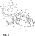
- the illustrated suspension arm assembly 10 includes conduits 22 for electricity, power, video, data, gases and/or liquids routed through the ceiling connector 12 and the boom arms 18 for the service head 14 (see FIG. 2 ).
- the illustrated ceiling connector 12 connects a first one of the boom arms 18 of the multi-link boom 16 to a support as illustrated in FIG. 2 .
- the ceiling connector 12 ( FIGS. 2 , 5 and 6 ) includes a center cylinder 24, a top plate 26, a bottom rim 31, a side connection arm 30 and a pivot pin 32.
- the side connection arm 30 has the first one of the boom arms 18 connected thereto for rotation about the pivot pin 32.
- the top plate 26 is configured to connect the ceiling connector 12, and thereby the entire suspension arm assembly 10, to a support.
- the top plate 26 can be stationary and fixed to the support or can be configured to pivot about the support. If pivotable, it is contemplated that the top plate 26 can have a limited range of motion relative to the support (e.g., by using stops).
- the ceiling connector 12 could have infinite rotation relative to the support by housing a slip ring or a fiber optic rotary joint therein (e.g., in the center cylinder 24), such as those disclosed in U.S. Patent Application Publication No. 2016/0091117 entitled FIBER OPTIC SLIP RING ROTARY JOINT FOR SUSPENSION ARM or in U.S. Patent Application No. 62/361 301 entitled SEPARABLE INFINITE ROTATION FIBER OPTIC AND SLIP RING ROTARY JOINT FOR SUSPENSION ARM, the entire contents of both of which are incorporated herein by reference.
- the center cylinder 24 is connected to a bottom of the top plate 26 and the bottom rim 31 is connected to a bottom of the center cylinder 24.
- the center cylinder 24 includes a bottom enclosure at the bottom rim 31 for enclosing a bottom of the center cylinder 24.
- the ceiling connector 12 includes the side connection arm 30 for connecting the boom arms 18 to the support for the suspension arm assembly 10.
- the center cylinder 24 is connected to a bottom of the top plate 26 and the side connection arm 30 extends laterally from an outside surface 28 of the center cylinder 24 (see FIG. 6 ).
- the conduits 22 extend around the top plate 26 and through a top wire routing holder 120 as discussed in more detail below.
- the pivot pin 32 allows the adjacent boom arm 18 to rotate about the ceiling connector 12.
- the side connection arm 30 includes a central block portion 40 that can include a plurality of cutouts 42 therethrough or therein to reduce weight of the side connection arm 30.
- the side connection arm 30 has an arcuate free end 44 having a plurality of vertical downwardly facing steps 46 becoming smaller going downward. The steps 46 allow for easy connection of the boom arm 18 to the ceiling connector 12 as discussed in more detail below.
- the illustrated pivot pin 32 is located in a vertical aperture 48 adjacent the arcuate free end 44 of the side connection arm 30.
- the pivot pin 32 includes a top portion 50 extending upwardly from a top surface 52 of the central block portion 40 of the side connection arm 30 and a bottom portion 54 extending downwardly from a bottom surface 56 of the central block portion 40 of the side connection arm 30.
- the top portion 50 includes a plurality of aligned cylinders including a lower cylinder 58, a middle cylinder 60 and an upper cylinder 62.
- the middle cylinder 60 extends into the central block portion 40 and includes at least one internal step supported on ledges within the vertical aperture 48 for supporting the pivot pin 32 within the central block portion 40.
- the bottom portion 54 of the pivot pin 32 includes a plurality of aligned cylinders including a top cylinder 64 and a bottom cylinder 66. It is contemplated that the top portion 50 and the bottom portion 54 of the pivot pin 32 can be integral or separate.
- the boom arm 18 adjacent the ceiling connector 12 pivots about the pivot pin 32.
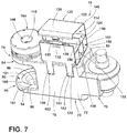
- the boom arm 18 ( FIGS. 7 and 8 ) includes a hollow structural main portion 70 having a central body 72, a proximal connection portion 74 and a boom arm side connection arm 76.
- the structural main portion 70 is hollow, but comprises the load bearing portion of the boom arm 18 for supporting the load (e.g., the weight of the arms distal to the present arm 18 and the service head 14) at the end of the multi-link boom 16.
- the central body 72 has a substantially rectangular cross-sectional shape with a pair of side walls 78, a top wall 80 and a bottom wall 82.
- the illustrated proximal connection portion 74 of the structural main portion 70 of the first boom arm 18 is located adjacent the ceiling connector 12 and connects the first boom arm 18 to the ceiling connector 12.
- the proximal connection portion 74 includes a proximal side top connection plate 84 extending laterally from the top wall 80 of the central body 72 and a proximal side bottom connection plate 86 extending laterally from the bottom wall 82 of the central body 72.
- the proximal side top connection plate 84 includes a top pin opening for accepting the middle cylinder 60 of the top portion 50 of the pivot pin 32 of the ceiling connector 12 therein.
- a top bushing can be located within the top pin opening between a peripheral wall thereof and a top bearing race 88 surrounding the middle cylinder 60 of the top portion 50 of the pivot pin 32 for allowing the first boom arm 18 to easily rotate about the pivot pin 32.
- a top bearing race 88 is shown about a pivot pin 32' of the first boom arm 18 in FIGS. 7 and 8 , which is identical to the pivot pin 32 of the ceiling connector 12 as discussed in more detail below.
- the proximal side bottom connection plate 86 includes a pair of fingers 90 and a C-shaped lock flange 92 connected to ends 94 of the fingers 90.
- the C-shaped lock flange 92 is not connected to the fingers 90, thereby allowing the bottom portion 54 of the pivot pin 32 to be received within an arcuate surface 96 between the fingers 90.
- a bottom bushing 101 and a bottom bearing race 98 are positioned on the bottom portion 54 of the pivot pin 32 for allowing the first boom arm 18 to easily rotate about the pivot pin 32.
- a bottom bearing race 98 is shown about a pivot pin 32' of the first boom arm 18 in FIGS. 7 and 8 .
- the illustrated boom arm 18 includes a brake system 104 for selectively preventing rotation of the boom arm 18 adjacent the ceiling connector 12 about the pivot pin 32.
- the pivot pin 32 is fixed in position in the vertical aperture 48 of the ceiling connector 12 and selectively locked in position relative to the adjacent boom arm 18 by the brake system 104.
- the brake system 104 is disc-shaped and includes a central opening 108. The upper cylinder 62 of the top portion 50 of the pivot pin 32 is received within the central opening 108 of the brake system 104. As shown in FIG.
- the upper cylinder 62 of the top portion 50 includes a laterally extending lock pin 106.
- the lock pin 106 is located within a circular run 110 outside the central opening 108 of the brake system 104.
- the brake system 104 is configured to selectively stop movement of the lock pin 106, thereby preventing rotation of the boom arm 18 about the pivot pin 32 and locking the boom arm 18 is position relative to the boom arm 18.
- the boom arm side connection arm 76 of the boom arm 18 is identical to the side connection arm 30 of the ceiling connector 12 and includes the pivot pin 32', which is identical to the pivot pin 32, such that a detailed discussion of the boom arm side connection arm 76, the pivot pin 32' and connection thereof to an adjacent boom arm 18 is not necessary.
- the boom arm side connection arm 76 of the boom arm 18 allows the boom arm 18 to be connected to an adjacent boom arm 18 as illustrated in FIG. 3 .
- Each boom arm 18 forming the multi-link boom 16 is either connected to the ceiling connector 12 or an adjacent boom arm 18. Furthermore, all boom arms 18 except for the first boom arm 18 connected to the ceiling connector 12 and the last boom arm 18 connected to the service head 14 are flanked by a pair of boom arms 18.
- the illustrated conduits 22 of the suspension arm assembly 10 are supported by the boom arms 18, but are not located within (i.e., are outside of) the load bearing portion of the boom arm 18 comprising the structural main portion 70. Therefore, the conduits 22 have a larger range of motion for bending to prevent breakage of the conduits 22 and also allow for easier routing of and access to the wires in the boom arms 18.
- the conduits 22 are routed through a top wire routing holder 120.
- the top wire routing holder 120 includes a rectangular shell 122 having open ends 124.
- the shell 122 includes a top door 126 shown partially open in FIGS. 2-4 , 7 and 8 .
- the top door 126 includes a latch 128 having a hook 130 configured to be inserted into a hole 132 to close the top door 126 and form a periphery about the conduits 22. It is contemplated that the top door 126 can be pivotable about a living hinge 140 for allowing the top door 126 to rotate relative to the rest of the rectangular shell 122.
- the top wire routing holder 120 can include a plurality of partitions 150 forming dividing cells 152 for assisting in routing the conduits 22 and keeping the conduits 22 separate from other conduits 22 within the top wire routing holder 120.
- the top wire routing holder 120 can include a pair of resilient legs 160 that snap fit into slots 162 on each of the side walls 78 of the central body 72 to connect the top wire routing holder 120 to the structural main portion 70 of the boom arms 18.
- the service head 14 can include a boom connecting assembly 200 for connecting the multi-link boom 16 to the service head 14.
- the boom connecting assembly 200 can include a pivot connection 202 identical to the proximal connection portion 74 of the boom arms 18.
- the boom connecting assembly 200 connects to the pivot pin 32' of the adjacent boom arm 18 in the same manner that adjacent boom arms 18 are connected together such that additional discussion on the connection is not necessary.
- the boom connecting assembly 200 also includes a brake system 104 for breaking rotation of the service head 14 relative to the multi-link boom 16.
- the boom connecting assembly 200 also includes a funnel 210 for routing and accommodating the conduits 22 from the multi-link boom 16 to a drop tube (not shown) and a service head main portion 212 (see FIG. 1 ) along with accommodating the conduits to allow for rotation of the service head 14 and vertical movement of the service head 14.
- the conduits 22 are routed out of the top wire routing holder 120 of the last boom arm 18, through a collection gate 214 at a top edge of the funnel 210 and into a bottom tube 220 of the funnel 210.
- the conduits 22 are then routed through a pair of telescoping tubes 230 connected to the service head mean portion 212.
- the pair of telescoping tubes 230 allow for the pair of telescoping tubes 230 to be lowered and raised.
- each of the boom arms 18 includes the boom arm shell 20 thereon.
- the boom arm shells 20 allow for the multi-link boom 16 to be covered and allow for each boom arm 18 to rotate relative to an adjacent boom arm 18, the ceiling connector 12 or the service head 14.
- Each boom arm shell 20 includes a bottom surface, a top surface 300 and a pair of side surfaces 302.
- FIG. 9 illustrates a pair of boom arm shells 20 and the manner in which adjacent boom arm shells 20 move relative to each other and continue to cover the boom arms 18.
- Each side surface 302 of the boom arm shell 20 includes a rigid portion 304 and a flexible portion 306.
- the rigid portion 304 of each side surface 302 of the boom arm shell 20 covers a side of the boom arm 18 and includes a straight portion 310 and an arcuate portion 312.
- the arcuate portion 312 surrounds the pivot pin 32, 32' at the proximal side of the boom arm 18 (i.e., the side nearest the ceiling connector 12).
- Each straight portion 310 of the rigid portion 304 of the side surface 302 includes a pocket 330 accepting the flexible portion 306 of the side surface 302 of the adjacent boom arm shell 20. As the boom arms 18 rotate relative to each other, the flexible portions 306 slide further into and out of the pockets 330. The flexible portions 306 are sufficiently long to always cover the boom arms 18.
- the boom arm shells 20 could include a top split 375 with associated connector to allow the boom arm shells 20 to be positioned over the boom arms 18 by splitting the boom arm shells 20 at the top split 375, wrapping the boom arm shells 20 about the boom arms 18 and then connecting the boom arm shells 20 at the top split 375.
- the top split 375 may also be opened to allow easy access to the conduits 22 for placement and/or service.
- a service head cover 400 includes a pair of side surfaces 402 with an arcuate portion 404 covering the pivot pin 32' of the adjacent boom arm 18 and a flexible portion 406 received within the pocket 330 of the adjacent boom arm shell 20.
- a ceiling connector cover 500 includes a rigid side 502 with a pocket receiving the flexible portion 306 of the adjacent boom arm shell 20.
- the single boom sleeve 20a is a flexible tube with bellows or elastic material at seams thereof that covers all of the boom arms 18 (instead of the shells).
- While a particular braking assembly has been illustrated to allow the boom arms 18 to brake in a selected rotated position relative to each other, to the ceiling connector 12 and to the service head 14, it is contemplated that other schemes to lock the boom arms 18 in position could be used.
- other brake assemblies that prevent rotation about the pivot pins 32, 32' could be used.
- single pivot pins 32, 32' that connect at top and bottoms thereof to adjacent structures are illustrated, it is contemplated that the pivot pins 32, 32' could be configured as separate top portions and bottom portions.
- the brake systems 104 could be activated and deactivated in any manner.
- the service head 14 could include a button that is depressed to unlock the brake systems 104 to allow the boom arms 18 to rotate and that locks the brake systems when not depressed.
- a handle 603 on a shelf 601 connected to poles 600 of the service head or anywhere else on the service head 14 (or item at the end of the boom) could include a capacitance touch system to lock the suspension arm assembly 10 in a selected position once the handle 603 is released such that grasping the handle 603 allows the suspension arm assembly 10 to be moved to a selected position (either immediately or after a pre-programmed delay).
- a capacitance touch system that releases all brake systems when the handle 603 is grasped and that locks all brake systems when the handle 603 is released is described in U.S. Patent No. 4 517 632 entitled OPERATING THEATRE LAMP, the entire contents of which are incorporated herein by reference. If the surgical light 14a is used with the suspension arm assembly 10, the handle for the surgical light 14a could include the capacitance touch system.
- the brake system 104 can include a positive braking system or a clutch system for impeding rotational movement of the boom arms 18.
- the capacitance touch brake system could include a two-touch system wherein two spaced locations 605, 607 (see FIGS. 11A and 11B ) need to be simultaneously touched to release the brake systems 104 to allow the suspension arm assembly 10 to move. In the two-touch system, both of the locations 605, 607 must be touched at the same time. It is contemplated that there may be single or multiple instances of a first one of the locations 605 and/or single or multiple instances of a second one of the locations 607. FIGS.
- 11A and 11B illustrate two instances of the first one of the locations 605 and a single instance of the second one of the locations 607. It is contemplated that the locations 605, 607 can be activated by touching a thin plastic element with a wire affixed to an interior side of the element or through direct contact with a metallic element. If direct contact with a metallic element contact is employed, it is contemplated that the metallic element contact would not directly contact any other metals and would not sense any other metallic objects near the metallic element contact (e.g., by using insulating materials such as plastic washers and intermediate materials (for example, a polycarbonate spacer) between two metallic components). It is contemplated that if the wire affixed to a thin plastic element is used that the wire be distanced from other metal objects.
- Another version of the brake release system has the brake systems 104 releasing based upon both activation of a single capacitance touch sensor (e.g., one of the sensors 805 on the handle 803a in FIG. 13A or the sensor 807 on the handle 803b in FIG. 13B ) and a force sensor (e.g., the force sensors 810a in FIG. 13A or the sensors 810b in FIG. 13B ).
- the force sensors 810a, 810b can be a single sensor or multiple sensors anywhere on the service head or elsewhere (for example, as shown in FIGS. 13A and 13B ).
- the force sensor e.g., a load cell, a strain gauge, a torsion sensor or a pressure sensor
- the control system senses activation of the capacitance touch sensor
- the brake systems 104 release in a predictable manner.
- the suspension arm assembly 10 could include indicator light(s) anywhere thereon (e.g., on the handle), with the indicator light(s) indicating that the capacitance touch sensor is sensing contact and that the force sensor is sensing a force.
- a single light could illuminate when both sensors are activated or multiple lights could be used, one for each sensor.
- a force sensor alone could be used to release the brake systems 104 in a predictable manner.
- a brake release system of the suspension arm assembly 10 When a brake release system of the suspension arm assembly 10 is activated, it is contemplated that all of the brake systems 104 could be released at the same time to allow all of the booms arms 18 to move. Alternatively, it is contemplated that the brake systems 104 could be released in a particular order. For example, it is contemplated that the brake system 104 of the boom arm 18 closest to the service head 14 and the boom arm 18 connected to the ceiling connector 12 (or other support structure) release first and that after a predetermined time period the brake systems 104 adjacent to the already released brake systems are also released and so on until the brake system 104 (or brake systems) at a central location of the multi-link boom 16 are released. Such a system is illustrated in FIG.
- the brake systems 104a are released first, followed by the brake systems 104b after a certain time period and finally the brake system 104c after a certain time period.
- the brake system 104 at the service head 14 can be released first and then each adjacent brake system 104 moving toward the ceiling connector 12 can be released after a certain time period.
- the boom arm 18 closest to the service head 14 releases first and then each adjacent brake system 104 moving toward the ceiling connector 12 is released after a certain time period.
- the brake system 104 at the service head 14 can remain engaged even when all the other brake systems 104a, 104b, 104c, etc.
- each of the brake systems 104 could individually be selectively activated (or remain braked) with all remaining brake systems 104, 104a, 104b, 104c, etc. becoming released (or the opposite, with selected brake systems being released with all remaining being braked). For example, if only the brake system 104 of the most proximal joint and the middle joint are disengaged, the multi-link boom 16 would behave like a traditional, two-link boom. In general, it is contemplated that the brake systems 104 of any adjacent boom arms 18 could be selected to remain engaged when other brake systems 104 are disengaged by a user to move the multi-link boom 16.
- the braking control system can also incorporate position sensors (e.g. encoders, potentiometers) at each joint, and release subsequent joints after joints have articulated a distance, achieved a speed, or the arm has reached a predetermined posture.
- FIG. 12 illustrates schematically a powered movement system 700 for the boom arm assembly 10.
- the powered movement system 700 includes a first direction powered spool 702 and a second direction powered spool 704.
- the first direction powered spool 702 and the second direction powered spool 704 are located adjacent the ceiling connector 12 (or other support structure).
- the first direction powered spool 702 and the second direction powered spool 704 can be located on the ceiling connector 12 or on the boom arm 16 adjacent the ceiling connector 12.
- the first direction powered spool 702 includes a first link 706 wrapped thereon.
- the first link 706 can be flexible (e.g., cables or rope) or formed of rigid link sections.
- the first link 706 is connected to an end of the boom arm assembly 10 (e.g., to the service head 14 or the boom arm 18 adjacent the service head 14) at a first direction end point 708.
- the second direction powered spool 704 includes a second link 710 wrapped thereon.
- the second link 710 can be flexible (e.g., cables or rope) or formed of rigid link sections.
- the second link 710 is connected to an end of the boom arm assembly 10 (e.g., to the service head 14 or the boom arm 18 adjacent the service head 14) at a second direction end point 712.
- the illustrated powered movement system 700 is configured to assist in moving the service head 14.
- the first direction powered spool 702 and the second direction powered spool 704 can be selectively activated to pull in the first link 706 and the second link 710, respectively.
- the first link 706 is pulled, the end of the multi-link boom 16 moves in the first direction 714 as illustrated in FIG. 12 .
- the second link 710 is pulled, the end of the multi-link boom 16 moves in the second direction 716 as illustrated in FIG. 12 .
- the brake systems could be modulated or selectively activated to select which joints between adjacent boom arms 18 (and between the boom arms 18 and adjacent ceiling connectors and end device) are allowed to move.
- the joints between adjacent boom arms 18 may contain position sensors and a microprocessor could be used to implement a control system for the powered movement system 700.
- a microprocessor could be used to implement a control system for the powered movement system 700. If the first link 706 and the second link 710 are semirigid (e.g. spooled sheet metal), the powered movement system 700 could allow for pushing in addition to pulling forces to be applied.
- both the first direction powered spool 702 and the second direction powered spool 704 could be activated to fold the multi-link boom 16 into a fully retracted position. It is further contemplated that in addition to a winding or unwinding of the first direction powered spool 702 and the second direction powered spool 704, tension in the first link 706 and the second link 710 can be controlled (e.g., with pneumatic or hydraulic cylinders).
- the powered movement system 700 could be designed with the ability to learn movement if a preferred series of steps was desired to reach a desired location.
- the powered movement system 700 could unlock all brake system 104 along with both the first direction powered spool 702 and the second direction powered spool 704 to map a path of the service head 14 that would be saved as a preset.
- the powered movement system 700 could also be used to identify areas of the room where the boom arm assembly 10 would not be allowed to travel to prevent the boom arm assembly 10 from hitting walls or colliding with other ceiling mounted equipment. It is contemplated that the boom arm assembly 10 could require the user to engage and maintain the powered movement system 700 or that the boom arm assembly 10 could move under control solely of the powered movement system 700. It is also contemplated that instead of powered spools, other actuators (e.g., hydraulic and/or pneumatic linear actuators) could be used or a single spool could be used for pulling on a pair of links.
- powered spools other actuators (e.g., hydraulic and/or pneumatic linear actuators) could be used or a single spool could be used for pulling on a pair of links.
- the illustrated suspension arm assembly 10 having the multi-link boom 16 allows for easy movement of the service head 14 (or other device located on the end of the multi-link boom 16), compact storage and easy routing of at least one conduit. Since the multi-link boom 16 include many boom arms 18, the multi-link boom 16 can be easily adjusted around other objects in a room and can be folded to be in a compact configuration. Furthermore, since the boom arms 18 of the multi-link boom 16 are horizontally aligned, the suspension arm assembly 10 has a short vertical profile and thereby takes up less room than prior art suspension arm assemblies.
- each arm of the multi-link boom is illustrated as being substantially identical, it is contemplated that the arm closest to the ceiling attachment member could be the largest (e.g, be the longest and/or have the greatest thickness) and the end arm could be the smallest (e.g., be the shortest and/or have the slightest thickness), with each arm having a different size (e.g., length and/or thickness) or some adjacent arms have the same size (e.g., length and/or thickness).
- the illustrated suspension arm assembly 10 could also include a force sensor 900 (e.g., a load cell, a strain gauge, a torsion sensor or a pressure sensor) adjacent the ceiling connector 12 (see FIG. 1 ) for sensing a weight of the remainder of the suspension arm assembly 10 (i.e., the weight of the suspension arm assembly 10 distal to the sensor 900 or moving away from the ceiling connector 12). If the weight of the remainder of the suspension arm assembly 10 is too great, an indicator 901 can be illuminated to indicate that more weight should not be added to the suspension arm assembly 10 and that some weight should be removed. Weight can be lessened, for example, by removing elements of the service head 14 (or other item at the end of the multi-link boom 16) or shortening the multi-link boom 16.
- a force sensor 900 e.g., a load cell, a strain gauge, a torsion sensor or a pressure sensor
Landscapes
- Health & Medical Sciences (AREA)
- Engineering & Computer Science (AREA)
- Life Sciences & Earth Sciences (AREA)
- Surgery (AREA)
- General Engineering & Computer Science (AREA)
- Animal Behavior & Ethology (AREA)
- General Health & Medical Sciences (AREA)
- Public Health (AREA)
- Veterinary Medicine (AREA)
- Biomedical Technology (AREA)
- Oral & Maxillofacial Surgery (AREA)
- Nuclear Medicine, Radiotherapy & Molecular Imaging (AREA)
- Heart & Thoracic Surgery (AREA)
- Medical Informatics (AREA)
- Molecular Biology (AREA)
- Pathology (AREA)
- Mechanical Engineering (AREA)
- Architecture (AREA)
- Structural Engineering (AREA)
- Nursing (AREA)
- Civil Engineering (AREA)
- Forklifts And Lifting Vehicles (AREA)
- Manipulator (AREA)
- Accommodation For Nursing Or Treatment Tables (AREA)
- Surgical Instruments (AREA)
Abstract
Description
- This claims the benefit of
U.S. Provisional Application Serial No. 62/467 893, filed March 7, 2017 - The present invention relates to a suspension arm assembly, and in particular to a multi-link boom.
- Surgical service heads are configured to provide outlets for electricity, data, gases and/or fluids for use by the medical personnel in a medical room and/or to assist the medical personnel in the room to perform various functions. Moreover, surgical lights have been used in operating rooms to provide increased light to a specific area of the room. For example, the surgical light can be positioned within an operating room and can provide increased light to a specific area of a person being operated on within the operating room. Furthermore, surgical devices, such as speakers, joysticks, keyboards and cameras, have been used in operating rooms to provide information to a surgeon or other person in the operating room (e.g., images from a camera or patient vital information).
- It is desired to have an easier way to position the surgical devices.
- The present invention, according to one aspect, is directed to a suspension arm assembly including at least three horizontally aligned members relatively rotatable about each other, with each adjacent pair of members being connected to each other by a joint and with each of the at least three horizontally aligned members defining a load bearing periphery, and at least one conduit extending along the at least three horizontally aligned members, with the at least one conduit not being located within the load bearing periphery of the at least three horizontally aligned members.
- Yet another aspect of the present invention is to provide a medical suspension arm assembly including a ceiling attachment member for connecting the medical suspension arm assembly to a ceiling, at least three horizontally aligned members relatively rotatable about each other, with each adjacent pair of members being connected to each other by a joint and with each of the at least three horizontally aligned members defining a load bearing periphery, a medical device for providing medical services or information, and at least one conduit extending along the ceiling attachment member, with the at least three horizontally aligned members and to the medical device, the at least one conduit not being located within the load bearing periphery of the at least three horizontally aligned members.
- Another aspect of the present invention is to provide a medical suspension arm assembly including an attachment member for connecting the medical suspension arm assembly to a support structure, at least three horizontally aligned members relatively rotatable about each other, with each adjacent pair of members being connected to each other by a joint and with each of the at least three horizontally aligned members having an arm horizontal length smaller than 25% of a total horizontal length of all of the horizontally aligned members, a medical device for providing medical services or information, and at least one conduit extending along the ceiling attachment member, with the at least three horizontally aligned members and to the medical device, the at least one conduit being routed horizontally and not vertically between adjacent pairs of the horizontally aligned members.
- Yet another aspect of the present invention is to provide a medical suspension arm assembly. The medical suspension arm assembly includes an attachment member for connecting the medical suspension arm assembly to a support structure, at least three horizontally aligned members relatively rotatable about each other, with each adjacent pair of members being connected to each other by a joint, a medical device for providing medical services or information, and at least one conduit extending along the attachment member, the at least three horizontally aligned members and to the medical device. Each joint has a brake system for selectively preventing movement of adjacent ones of the at least three horizontally aligned members about the joint, with each brake system being located outside a periphery of an associated one of the at least three horizontally aligned members.
- Another aspect of the present invention is to provide a method of using a suspension arm assembly including providing at least three horizontally aligned members relatively rotatable about each other, connecting each adjacent pair of members to each other by a joint, with each of the at least three horizontally aligned members defining a load bearing periphery, and extending at least one conduit along the at least three horizontally aligned members, with the at least one conduit not being located within the load bearing periphery of the at least three horizontally aligned members.
- One or more embodiments of the present invention are illustrated by way of example and should not be construed as being limited to the specific embodiments depicted in the accompanying drawings, in which like reference numerals indicate similar elements.
-
FIG. 1A illustrates a perspective view of a first embodiment of a suspension arm assembly having a multi-link boom including a plurality of boom shells according to the present invention and including a service head connected thereto. -
FIG. 1B illustrates a perspective view of a second embodiment of a suspension arm assembly having the multi-link boom including a single boom sleeve according to the present invention and including the service head connected thereto. -
FIG. 1C illustrates a perspective view of a third embodiment of a suspension arm assembly having the multi-link boom including the plurality of boom shells according to the present invention and including a surgical light connected thereto. -
FIG. 2 is a perspective view of a ceiling connector and first boom arm of the multi-link boom according to the present invention. -
FIG. 3 is a perspective view of a pair of boom arms of the multi-link boom according to the present invention. -
FIG. 4 is a perspective view of an end boom arm of the multi-link boom according to the present invention connected to a service head connector. -
FIG. 5 is a perspective view of the ceiling connector according to the present invention. -
FIG. 6 is a side view of the ceiling connector according to the present invention. -
FIG. 7 is a perspective view of the boom arm according to the present invention. -
FIG. 8 is a side view of the boom arm according to the present invention. -
FIG. 9 is a schematic cross-sectional view of a pair of boom arm shells according to the present invention. -
FIG. 10 is a schematic view of the suspension arm assembly of the present invention illustrating a scheme for releasing brake systems of the present invention. -
FIG. 11A is a front perspective view of a shelf of the suspension arm assembly of the present invention illustrating a first method of moving the suspension arm assembly. -
FIG. 11B is a rear perspective view of a shelf of the suspension arm assembly of the present invention illustrating the first method of moving the suspension arm assembly. -
FIG. 12 is a top schematic view of the suspension arm assembly of the present invention having a powered system for moving the boom arms of the multi-link boom of the present invention. -
FIG. 13A is a front perspective view of a shelf of the suspension arm assembly of the present invention illustrating a second method of moving the suspension arm assembly. -
FIG. 13B is a rear perspective view of a shelf of the suspension arm assembly of the present invention illustrating a third method of moving the suspension arm assembly. - The specific devices and processes illustrated in the attached drawings, and described in the following specification are simply exemplary embodiments of the inventive concepts. Hence, specific dimensions and other physical characteristics relating to the embodiments disclosed herein are not to be considered as limiting.
- The reference number 10 (
FIG. 1A ) generally designates a suspension arm assembly of the present invention. Thesuspension arm assembly 10 includes aceiling connector 12, aservice head 14 and amulti-link boom 16 between theceiling connector 12 and theservice head 14. Themulti-link boom 16 includes a plurality of boom arms 18 (seeFIGS. 2-4 ,7 and8 ) each covered by aboom arm shell 20. Each of theboom arms 18 can rotate relative to each other to provide for multiple end locations for theservice head 14. The illustratedsuspension arm assembly 10 is configured to be positioned within a room (e.g., an operating room or a patient care area) and, in the illustrated embodiment, includes theservice head 14, which is configured to provide outlets for electricity, data, gases and/or fluids for use by the medical personnel in the room and/or to assist the medical personnel in the room in performing various functions. It is contemplated that other items (e.g., asurgical light 14a as illustrated inFIG. 1C , a display monitor, dual displays, cameras, microphones, etc.) can be located at the end of thesuspension arm assembly 10 instead of theservice head 14. - In the illustrated example, the
suspension arm assembly 10 is connected to a ceiling and supports theservice head 14 above a support surface, such as a floor. Thesuspension arm assembly 10 includes theceiling connector 12, themulti-link boom 16 and theservice head 14. While themulti-link boom 16 is illustrated as having fiveboom arms 18, it is contemplated that thesuspension arm assembly 10 could have any number ofboom arms 18. Furthermore, while thesuspension arm assembly 10 includes theceiling connector 12 for connecting thesuspension arm assembly 10 to a ceiling, it is contemplated that theceiling connector 12 could be used to connect thesuspension arm assembly 10 to any structure (fixed or movable) above a support surface, such as a floor, wall or pedestal. Moreover, as discussed in more detail below, themulti-link boom 16 can include a single,flexible boom sleeve 20a (seeFIG. 1B ) functioning as a bellows and/or is elastic at joints instead of a plurality ofboom arm shells 20 covering themulti-link boom 16. The illustratedsuspension arm assembly 10 includesconduits 22 for electricity, power, video, data, gases and/or liquids routed through theceiling connector 12 and theboom arms 18 for the service head 14 (seeFIG. 2 ). - The illustrated
ceiling connector 12 connects a first one of theboom arms 18 of themulti-link boom 16 to a support as illustrated inFIG. 2 . The ceiling connector 12 (FIGS. 2 ,5 and6 ) includes acenter cylinder 24, atop plate 26, abottom rim 31, aside connection arm 30 and apivot pin 32. Theside connection arm 30 has the first one of theboom arms 18 connected thereto for rotation about thepivot pin 32. Thetop plate 26 is configured to connect theceiling connector 12, and thereby the entiresuspension arm assembly 10, to a support. Thetop plate 26 can be stationary and fixed to the support or can be configured to pivot about the support. If pivotable, it is contemplated that thetop plate 26 can have a limited range of motion relative to the support (e.g., by using stops). If theconduits 22 only carry electricity, power, video or data, it is contemplated that the ceiling connector 12 (or adjacent structure) could have infinite rotation relative to the support by housing a slip ring or a fiber optic rotary joint therein (e.g., in the center cylinder 24), such as those disclosed inU.S. Patent Application Publication No. 2016/0091117 entitled FIBER OPTIC SLIP RING ROTARY JOINT FOR SUSPENSION ARM or inU.S. Patent Application No. 62/361 301 center cylinder 24 is connected to a bottom of thetop plate 26 and thebottom rim 31 is connected to a bottom of thecenter cylinder 24. Thecenter cylinder 24 includes a bottom enclosure at thebottom rim 31 for enclosing a bottom of thecenter cylinder 24. - In the illustrated example, the
ceiling connector 12 includes theside connection arm 30 for connecting theboom arms 18 to the support for thesuspension arm assembly 10. Thecenter cylinder 24 is connected to a bottom of thetop plate 26 and theside connection arm 30 extends laterally from anoutside surface 28 of the center cylinder 24 (seeFIG. 6 ). As shown inFIG. 2 , theconduits 22 extend around thetop plate 26 and through a topwire routing holder 120 as discussed in more detail below. Thepivot pin 32 allows theadjacent boom arm 18 to rotate about theceiling connector 12. Theside connection arm 30 includes acentral block portion 40 that can include a plurality ofcutouts 42 therethrough or therein to reduce weight of theside connection arm 30. Theside connection arm 30 has an arcuatefree end 44 having a plurality of vertical downwardly facingsteps 46 becoming smaller going downward. Thesteps 46 allow for easy connection of theboom arm 18 to theceiling connector 12 as discussed in more detail below. - The illustrated
pivot pin 32 is located in avertical aperture 48 adjacent the arcuatefree end 44 of theside connection arm 30. As illustrated inFIGS 5 and6 , thepivot pin 32 includes atop portion 50 extending upwardly from atop surface 52 of thecentral block portion 40 of theside connection arm 30 and abottom portion 54 extending downwardly from abottom surface 56 of thecentral block portion 40 of theside connection arm 30. Thetop portion 50 includes a plurality of aligned cylinders including alower cylinder 58, amiddle cylinder 60 and anupper cylinder 62. Themiddle cylinder 60 extends into thecentral block portion 40 and includes at least one internal step supported on ledges within thevertical aperture 48 for supporting thepivot pin 32 within thecentral block portion 40. Thebottom portion 54 of thepivot pin 32 includes a plurality of aligned cylinders including atop cylinder 64 and abottom cylinder 66. It is contemplated that thetop portion 50 and thebottom portion 54 of thepivot pin 32 can be integral or separate. - In the illustrated example, the
boom arm 18 adjacent theceiling connector 12 pivots about thepivot pin 32. The boom arm 18 (FIGS. 7 and8 ) includes a hollow structuralmain portion 70 having acentral body 72, aproximal connection portion 74 and a boom armside connection arm 76. The structuralmain portion 70 is hollow, but comprises the load bearing portion of theboom arm 18 for supporting the load (e.g., the weight of the arms distal to thepresent arm 18 and the service head 14) at the end of themulti-link boom 16. Thecentral body 72 has a substantially rectangular cross-sectional shape with a pair ofside walls 78, atop wall 80 and abottom wall 82. - The illustrated
proximal connection portion 74 of the structuralmain portion 70 of thefirst boom arm 18 is located adjacent theceiling connector 12 and connects thefirst boom arm 18 to theceiling connector 12. Theproximal connection portion 74 includes a proximal sidetop connection plate 84 extending laterally from thetop wall 80 of thecentral body 72 and a proximal sidebottom connection plate 86 extending laterally from thebottom wall 82 of thecentral body 72. The proximal sidetop connection plate 84 includes a top pin opening for accepting themiddle cylinder 60 of thetop portion 50 of thepivot pin 32 of theceiling connector 12 therein. A top bushing can be located within the top pin opening between a peripheral wall thereof and atop bearing race 88 surrounding themiddle cylinder 60 of thetop portion 50 of thepivot pin 32 for allowing thefirst boom arm 18 to easily rotate about thepivot pin 32. Atop bearing race 88 is shown about a pivot pin 32' of thefirst boom arm 18 inFIGS. 7 and8 , which is identical to thepivot pin 32 of theceiling connector 12 as discussed in more detail below. During assembly, thetop portion 50 of thepivot pin 32 of theceiling connector 12 is inserted into the top pin opening of the proximal sidetop connection plate 84 and the structuralmain portion 70 is rotated clockwise as viewed in the orientation ofFIG. 2 to connect theceiling connector 12 to thefirst boom arm 18. Thesteps 46 of the arcuatefree end 44 of theside connection arm 30 of theceiling connector 12 provide clearance for the proximal sidebottom connection plate 86 to be positioned under theside connection arm 30 of theceiling connector 12. - In the illustrated example, the proximal side
bottom connection plate 86 includes a pair offingers 90 and a C-shapedlock flange 92 connected to ends 94 of thefingers 90. During connection of theboom arm 18 to theceiling connector 12, the C-shapedlock flange 92 is not connected to thefingers 90, thereby allowing thebottom portion 54 of thepivot pin 32 to be received within anarcuate surface 96 between thefingers 90. Abottom bushing 101 and abottom bearing race 98 are positioned on thebottom portion 54 of thepivot pin 32 for allowing thefirst boom arm 18 to easily rotate about thepivot pin 32. Abottom bearing race 98 is shown about a pivot pin 32' of thefirst boom arm 18 inFIGS. 7 and8 . After thebottom bushing 101, thebottom bearing race 98 and thebottom portion 54 of thepivot pin 32 are received within thearcuate surface 96 between thefingers 90, ends 100 of the C-shapedlock flange 92 are positioned against theends 94 of thefingers 90 and fasteners are inserted intoopenings 102 in the C-shapedlock flange 92 and into thefingers 90 to form the proximal sidebottom connection plate 86 and thereby fix thefirst boom arm 18 to theceiling connector 12. - The
illustrated boom arm 18 includes abrake system 104 for selectively preventing rotation of theboom arm 18 adjacent theceiling connector 12 about thepivot pin 32. In the illustrated example, thepivot pin 32 is fixed in position in thevertical aperture 48 of theceiling connector 12 and selectively locked in position relative to theadjacent boom arm 18 by thebrake system 104. However, it is contemplated that thepivot pin 32 could be fixed in position relative to theboom arm 18 and selectively locked in position relative to theceiling connector 12 by thebrake system 104. As illustrated inFIG. 7 , thebrake system 104 is disc-shaped and includes acentral opening 108. Theupper cylinder 62 of thetop portion 50 of thepivot pin 32 is received within thecentral opening 108 of thebrake system 104. As shown inFIG. 6 , theupper cylinder 62 of thetop portion 50 includes a laterally extendinglock pin 106. Thelock pin 106 is located within acircular run 110 outside thecentral opening 108 of thebrake system 104.
Thebrake system 104 is configured to selectively stop movement of thelock pin 106, thereby preventing rotation of theboom arm 18 about thepivot pin 32 and locking theboom arm 18 is position relative to theboom arm 18. - In the illustrated example, the boom arm
side connection arm 76 of theboom arm 18 is identical to theside connection arm 30 of theceiling connector 12 and includes the pivot pin 32', which is identical to thepivot pin 32, such that a detailed discussion of the boom armside connection arm 76, the pivot pin 32' and connection thereof to anadjacent boom arm 18 is not necessary. The boom armside connection arm 76 of theboom arm 18 allows theboom arm 18 to be connected to anadjacent boom arm 18 as illustrated inFIG. 3 . Eachboom arm 18 forming themulti-link boom 16 is either connected to theceiling connector 12 or anadjacent boom arm 18. Furthermore, all boomarms 18 except for thefirst boom arm 18 connected to theceiling connector 12 and thelast boom arm 18 connected to theservice head 14 are flanked by a pair ofboom arms 18. - The illustrated
conduits 22 of thesuspension arm assembly 10 are supported by theboom arms 18, but are not located within (i.e., are outside of) the load bearing portion of theboom arm 18 comprising the structuralmain portion 70. Therefore, theconduits 22 have a larger range of motion for bending to prevent breakage of theconduits 22 and also allow for easier routing of and access to the wires in theboom arms 18. As illustrated inFIG. 2 , theconduits 22 are routed through a topwire routing holder 120. The topwire routing holder 120 includes arectangular shell 122 having open ends 124. Theshell 122 includes atop door 126 shown partially open inFIGS. 2-4 ,7 and8 . Thetop door 126 includes alatch 128 having ahook 130 configured to be inserted into ahole 132 to close thetop door 126 and form a periphery about theconduits 22. It is contemplated that thetop door 126 can be pivotable about aliving hinge 140 for allowing thetop door 126 to rotate relative to the rest of therectangular shell 122. The topwire routing holder 120 can include a plurality ofpartitions 150 forming dividingcells 152 for assisting in routing theconduits 22 and keeping theconduits 22 separate fromother conduits 22 within the topwire routing holder 120. The topwire routing holder 120 can include a pair ofresilient legs 160 that snap fit intoslots 162 on each of theside walls 78 of thecentral body 72 to connect the topwire routing holder 120 to the structuralmain portion 70 of theboom arms 18. - In the illustrated example, the
last boom arm 18 is connected to theservice head 14. As illustrated inFIG. 4 , theservice head 14 can include aboom connecting assembly 200 for connecting themulti-link boom 16 to theservice head 14. Theboom connecting assembly 200 can include apivot connection 202 identical to theproximal connection portion 74 of theboom arms 18. Theboom connecting assembly 200 connects to the pivot pin 32' of theadjacent boom arm 18 in the same manner thatadjacent boom arms 18 are connected together such that additional discussion on the connection is not necessary. Theboom connecting assembly 200 also includes abrake system 104 for breaking rotation of theservice head 14 relative to themulti-link boom 16. Theboom connecting assembly 200 also includes afunnel 210 for routing and accommodating theconduits 22 from themulti-link boom 16 to a drop tube (not shown) and a service head main portion 212 (seeFIG. 1 ) along with accommodating the conduits to allow for rotation of theservice head 14 and vertical movement of theservice head 14. Theconduits 22 are routed out of the topwire routing holder 120 of thelast boom arm 18, through acollection gate 214 at a top edge of thefunnel 210 and into abottom tube 220 of thefunnel 210. Theconduits 22 are then routed through a pair oftelescoping tubes 230 connected to the service head meanportion 212. The pair oftelescoping tubes 230 allow for the pair oftelescoping tubes 230 to be lowered and raised. - In the illustrated example, each of the
boom arms 18 includes theboom arm shell 20 thereon. Theboom arm shells 20 allow for themulti-link boom 16 to be covered and allow for eachboom arm 18 to rotate relative to anadjacent boom arm 18, theceiling connector 12 or theservice head 14. Eachboom arm shell 20 includes a bottom surface, atop surface 300 and a pair of side surfaces 302.FIG. 9 illustrates a pair ofboom arm shells 20 and the manner in which adjacentboom arm shells 20 move relative to each other and continue to cover theboom arms 18. Eachside surface 302 of theboom arm shell 20 includes arigid portion 304 and aflexible portion 306. Therigid portion 304 of eachside surface 302 of theboom arm shell 20 covers a side of theboom arm 18 and includes astraight portion 310 and anarcuate portion 312. Thearcuate portion 312 surrounds thepivot pin 32, 32' at the proximal side of the boom arm 18 (i.e., the side nearest the ceiling connector 12). Eachstraight portion 310 of therigid portion 304 of theside surface 302 includes apocket 330 accepting theflexible portion 306 of theside surface 302 of the adjacentboom arm shell 20. As theboom arms 18 rotate relative to each other, theflexible portions 306 slide further into and out of thepockets 330. Theflexible portions 306 are sufficiently long to always cover theboom arms 18. It is contemplated that theboom arm shells 20 could include atop split 375 with associated connector to allow theboom arm shells 20 to be positioned over theboom arms 18 by splitting theboom arm shells 20 at thetop split 375, wrapping theboom arm shells 20 about theboom arms 18 and then connecting theboom arm shells 20 at thetop split 375. Thetop split 375 may also be opened to allow easy access to theconduits 22 for placement and/or service. - As illustrated in
FIG. 1 , aservice head cover 400 includes a pair of side surfaces 402 with anarcuate portion 404 covering the pivot pin 32' of theadjacent boom arm 18 and aflexible portion 406 received within thepocket 330 of the adjacentboom arm shell 20. Likewise, aceiling connector cover 500 includes arigid side 502 with a pocket receiving theflexible portion 306 of the adjacentboom arm shell 20. InFIG. 1B , thesingle boom sleeve 20a is a flexible tube with bellows or elastic material at seams thereof that covers all of the boom arms 18 (instead of the shells). - While a particular braking assembly has been illustrated to allow the
boom arms 18 to brake in a selected rotated position relative to each other, to theceiling connector 12 and to theservice head 14, it is contemplated that other schemes to lock theboom arms 18 in position could be used. For example, other brake assemblies that prevent rotation about the pivot pins 32, 32' could be used. Furthermore, while single pivot pins 32, 32' that connect at top and bottoms thereof to adjacent structures are illustrated, it is contemplated that the pivot pins 32, 32' could be configured as separate top portions and bottom portions. - Furthermore, it is contemplated that the
brake systems 104 could be activated and deactivated in any manner. For example, theservice head 14 could include a button that is depressed to unlock thebrake systems 104 to allow theboom arms 18 to rotate and that locks the brake systems when not depressed. Moreover, it is contemplated that ahandle 603 on ashelf 601 connected topoles 600 of the service head or anywhere else on the service head 14 (or item at the end of the boom) could include a capacitance touch system to lock thesuspension arm assembly 10 in a selected position once thehandle 603 is released such that grasping thehandle 603 allows thesuspension arm assembly 10 to be moved to a selected position (either immediately or after a pre-programmed delay). A capacitance touch system that releases all brake systems when thehandle 603 is grasped and that locks all brake systems when thehandle 603 is released is described inU.S. Patent No. 4 517 632 entitled OPERATING THEATRE LAMP, the entire contents of which are incorporated herein by reference. If thesurgical light 14a is used with thesuspension arm assembly 10, the handle for thesurgical light 14a could include the capacitance touch system. Thebrake system 104 can include a positive braking system or a clutch system for impeding rotational movement of theboom arms 18. - In the illustrated example, if a capacitance touch brake system is used, there could be a single location that needs to be touched to release the
brake systems 104. Alternatively, the capacitance touch brake system could include a two-touch system wherein two spacedlocations 605, 607 (seeFIGS. 11A and 11B ) need to be simultaneously touched to release thebrake systems 104 to allow thesuspension arm assembly 10 to move. In the two-touch system, both of thelocations locations 605 and/or single or multiple instances of a second one of thelocations 607.FIGS. 11A and 11B illustrate two instances of the first one of thelocations 605 and a single instance of the second one of thelocations 607. It is contemplated that thelocations - Another version of the brake release system has the
brake systems 104 releasing based upon both activation of a single capacitance touch sensor (e.g., one of the sensors 805 on thehandle 803a inFIG. 13A or the sensor 807 on thehandle 803b inFIG. 13B ) and a force sensor (e.g., theforce sensors 810a inFIG. 13A or thesensors 810b inFIG. 13B ). Theforce sensors FIGS. 13A and 13B ). As the force sensor (e.g., a load cell, a strain gauge, a torsion sensor or a pressure sensor) senses a force and the control system senses activation of the capacitance touch sensor, thebrake systems 104 release in a predictable manner. It is contemplated that thesuspension arm assembly 10 could include indicator light(s) anywhere thereon (e.g., on the handle), with the indicator light(s) indicating that the capacitance touch sensor is sensing contact and that the force sensor is sensing a force. For example, a single light could illuminate when both sensors are activated or multiple lights could be used, one for each sensor. It is contemplated that a force sensor alone could be used to release thebrake systems 104 in a predictable manner. - When a brake release system of the
suspension arm assembly 10 is activated, it is contemplated that all of thebrake systems 104 could be released at the same time to allow all of thebooms arms 18 to move. Alternatively, it is contemplated that thebrake systems 104 could be released in a particular order. For example, it is contemplated that thebrake system 104 of theboom arm 18 closest to theservice head 14 and theboom arm 18 connected to the ceiling connector 12 (or other support structure) release first and that after a predetermined time period thebrake systems 104 adjacent to the already released brake systems are also released and so on until the brake system 104 (or brake systems) at a central location of themulti-link boom 16 are released. Such a system is illustrated inFIG. 10 wherein thebrake systems 104a are released first, followed by thebrake systems 104b after a certain time period and finally thebrake system 104c after a certain time period. Alternatively, it is contemplated that thebrake system 104 at theservice head 14 can be released first and then eachadjacent brake system 104 moving toward theceiling connector 12 can be released after a certain time period. For example, when the user engages the brake release system and exerts force to the right, theboom arm 18 closest to theservice head 14 releases first and then eachadjacent brake system 104 moving toward theceiling connector 12 is released after a certain time period. It is further contemplated that thebrake system 104 at theservice head 14 can remain engaged even when all theother brake systems brake systems 104 could individually be selectively activated (or remain braked) with all remainingbrake systems brake system 104 of the most proximal joint and the middle joint are disengaged, themulti-link boom 16 would behave like a traditional, two-link boom. In general, it is contemplated that thebrake systems 104 of anyadjacent boom arms 18 could be selected to remain engaged whenother brake systems 104 are disengaged by a user to move themulti-link boom 16. The braking control system can also incorporate position sensors (e.g. encoders, potentiometers) at each joint, and release subsequent joints after joints have articulated a distance, achieved a speed, or the arm has reached a predetermined posture. -
FIG. 12 illustrates schematically apowered movement system 700 for theboom arm assembly 10. Thepowered movement system 700 includes a first direction poweredspool 702 and a second direction poweredspool 704. The first direction poweredspool 702 and the second direction poweredspool 704 are located adjacent the ceiling connector 12 (or other support structure). For example, the first direction poweredspool 702 and the second direction poweredspool 704 can be located on theceiling connector 12 or on theboom arm 16 adjacent theceiling connector 12. The first direction poweredspool 702 includes afirst link 706 wrapped thereon. Thefirst link 706 can be flexible (e.g., cables or rope) or formed of rigid link sections. Thefirst link 706 is connected to an end of the boom arm assembly 10 (e.g., to theservice head 14 or theboom arm 18 adjacent the service head 14) at a firstdirection end point 708. Likewise, the second direction poweredspool 704 includes asecond link 710 wrapped thereon. Thesecond link 710 can be flexible (e.g., cables or rope) or formed of rigid link sections. Thesecond link 710 is connected to an end of the boom arm assembly 10 (e.g., to theservice head 14 or theboom arm 18 adjacent the service head 14) at a seconddirection end point 712. - The illustrated
powered movement system 700 is configured to assist in moving theservice head 14. Under control of a control system, the first direction poweredspool 702 and the second direction poweredspool 704 can be selectively activated to pull in thefirst link 706 and thesecond link 710, respectively. When thefirst link 706 is pulled, the end of themulti-link boom 16 moves in thefirst direction 714 as illustrated inFIG. 12 . Likewise, when thesecond link 710 is pulled, the end of themulti-link boom 16 moves in thesecond direction 716 as illustrated inFIG. 12 . In the illustrated example, the brake systems could be modulated or selectively activated to select which joints between adjacent boom arms 18 (and between theboom arms 18 and adjacent ceiling connectors and end device) are allowed to move. In such a system, the joints between adjacent boom arms 18 (and between theboom arms 18 and adjacent ceiling connectors and end device) may contain position sensors and a microprocessor could be used to implement a control system for thepowered movement system 700. If thefirst link 706 and thesecond link 710 are semirigid (e.g. spooled sheet metal), thepowered movement system 700 could allow for pushing in addition to pulling forces to be applied. - In the illustrated example, itis contemplated that both the first direction powered
spool 702 and the second direction poweredspool 704 could be activated to fold themulti-link boom 16 into a fully retracted position. It is further contemplated that in addition to a winding or unwinding of the first direction poweredspool 702 and the second direction poweredspool 704, tension in thefirst link 706 and thesecond link 710 can be controlled (e.g., with pneumatic or hydraulic cylinders). Thepowered movement system 700 could be designed with the ability to learn movement if a preferred series of steps was desired to reach a desired location. For example, thepowered movement system 700 could unlock allbrake system 104 along with both the first direction poweredspool 702 and the second direction poweredspool 704 to map a path of theservice head 14 that would be saved as a preset. Thepowered movement system 700 could also be used to identify areas of the room where theboom arm assembly 10 would not be allowed to travel to prevent theboom arm assembly 10 from hitting walls or colliding with other ceiling mounted equipment. It is contemplated that theboom arm assembly 10 could require the user to engage and maintain thepowered movement system 700 or that theboom arm assembly 10 could move under control solely of thepowered movement system 700. It is also contemplated that instead of powered spools, other actuators (e.g., hydraulic and/or pneumatic linear actuators) could be used or a single spool could be used for pulling on a pair of links. - The illustrated
suspension arm assembly 10 having themulti-link boom 16 allows for easy movement of the service head 14 (or other device located on the end of the multi-link boom 16), compact storage and easy routing of at least one conduit. Since themulti-link boom 16 includemany boom arms 18, themulti-link boom 16 can be easily adjusted around other objects in a room and can be folded to be in a compact configuration. Furthermore, since theboom arms 18 of themulti-link boom 16 are horizontally aligned, thesuspension arm assembly 10 has a short vertical profile and thereby takes up less room than prior art suspension arm assemblies. While each arm of the multi-link boom is illustrated as being substantially identical, it is contemplated that the arm closest to the ceiling attachment member could be the largest (e.g, be the longest and/or have the greatest thickness) and the end arm could be the smallest (e.g., be the shortest and/or have the slightest thickness), with each arm having a different size (e.g., length and/or thickness) or some adjacent arms have the same size (e.g., length and/or thickness). - The illustrated
suspension arm assembly 10 could also include a force sensor 900 (e.g., a load cell, a strain gauge, a torsion sensor or a pressure sensor) adjacent the ceiling connector 12 (seeFIG. 1 ) for sensing a weight of the remainder of the suspension arm assembly 10 (i.e., the weight of thesuspension arm assembly 10 distal to thesensor 900 or moving away from the ceiling connector 12). If the weight of the remainder of thesuspension arm assembly 10 is too great, anindicator 901 can be illuminated to indicate that more weight should not be added to thesuspension arm assembly 10 and that some weight should be removed. Weight can be lessened, for example, by removing elements of the service head 14 (or other item at the end of the multi-link boom 16) or shortening themulti-link boom 16. - Although particular preferred embodiments of the invention have been disclosed in detail for illustrative purposes, it will be recognized that variations or modifications of the disclosed apparatus, including the rearrangement of parts, lie within the scope of the present invention.
Claims (15)
- A suspension arm assembly comprising:at least three horizontally aligned members relatively rotatable about each other, each adjacent pair of members being connected to each other by a joint, each of the at least three horizontally aligned members defining a load bearing periphery; andat least one conduit extending along the at least three horizontally aligned members, the at least one conduit not being located within the load bearing periphery of the at least three horizontally aligned members.
- A medical suspension arm assembly comprising:an attachment member for connecting the medical suspension arm assembly to a support structure;at least three horizontally aligned members relatively rotatable about each other, each adjacent pair of members being connected to each other by a joint;a medical device for providing medical services or information; andat least one conduit extending along the attachment member, the at least three horizontally aligned members and to the medical device, the at least one conduit being routed horizontally and not vertically between adjacent pairs of the horizontally aligned members, and in particular wherein:
at least one of the at least three horizontally aligned members have an arm horizontal length smaller than 25% of a total horizontal length of all of the horizontally aligned members. - A medical suspension arm assembly comprising:an attachment member for connecting the medical suspension arm assembly to a support structure;at least three horizontally aligned members relatively rotatable about each other, each adjacent pair of members being connected to each other by a joint;a medical device for providing medical services or information; andat least one conduit extending along the attachment member, the at least three horizontally aligned members and to the medical device;each joint having a brake system for selectively preventing movement of adjacent ones of the at least three horizontally aligned members about the joint, with each brake system being located outside a periphery of an associated one of the at least three horizontally aligned members, and in particular wherein:the brake system provides for sequential release of brakes of the brake system, or wherein:each brake system is released when at least two spaced capacitance touch sensors are touched along with a force sensor sensing a movement force.
- The suspension arm assembly of Claim 1 or Claim 3, wherein:
the at least one conduit is routed horizontally and not vertically between adjacent pairs of the horizontally aligned members. - The suspension arm assembly of Claims 1-3, further including:at least one boom shell about the at least three horizontally aligned members;wherein each of the horizontally aligned members includes a at least one conduit routing housing located between the load bearing periphery and the at least one boom shell, each at least one conduit routing housing having the at least one conduit being routed therethrough.
- The suspension arm assembly of Claims 1-3, further including:
a boom shell about each of the at least three horizontally aligned members. - The suspension arm assembly of Claims 1-3, wherein:
each of the horizontally aligned members includes at least one conduit routing housing located outside of the load bearing periphery and having the at least one conduit therein. - The suspension arm assembly of Claims 1-3, wherein:
each of the horizontally aligned members includes a pivot pin located between adjacent pairs of the horizontally aligned members, each pivot pin engaging a brake system for selectively preventing rotation of at least one of the adjacent pairs of the horizontally aligned members from rotating about the pivot pin. - The suspension arm assembly of Claim 8, wherein:
each of the horizontally aligned members includes a removable C-shaped flange for selectively locking the pivot pin in position on the horizontally aligned members. - The suspension arm assembly of Claim 8, wherein:
each brake system is released by activating at least two sensors. - The suspension arm assembly of Claim 10, wherein:
the at least two sensors comprise at least two spaced capacitance touch sensors. - The suspension arm assembly of Claims 1-3, wherein:
each of the horizontally aligned members are hollow and have a substantially rectangular cross-sectional shape, or wherein:
at least two of the at least three horizontally aligned members are substantially identical, or further including:
a powered system for selectively causing rotations of at least two of the at least three horizontally aligned members about each other, or further including:
a brake system for selectively preventing rotation of at least one of the adjacent pairs of the horizontally aligned members. - The suspension arm assembly of Claim 12, wherein:
the brake system provides for sequential release of brakes of the brake system. - The suspension arm assembly of Claim 1, further including:a ceiling attachment member for connecting the suspension arm assembly to a ceiling at a first end of the suspension arm assembly; anda medical device for providing medical services or information at a second end of the suspension arm assembly, and in particular wherein:the medical device comprises a service head, or wherein:the medical device comprises a surgical light.
- A method of using a suspension arm assembly comprising:providing at least three horizontally aligned members relatively rotatable about each other;connecting each adjacent pair of members to each other by a joint, each of the at least three horizontally aligned members defining a load bearing periphery; andextending at least one conduit along the at least three horizontally aligned members, the at least one conduit not being located within the load bearing periphery of the at least three horizontally aligned members, and in particular further including:
providing a brake system for selectively preventing rotation of at least one of the adjacent pairs of the horizontally aligned members, or further including:
sequentially releasing brakes of the brake system, or wherein:the brake system comprises a brake between the adjacent pairs of the horizontally aligned members; andfurther including releasing at least one but not all of the brakes to reduce degrees of freedom of movement of the suspension arm assembly.
Applications Claiming Priority (1)
| Application Number | Priority Date | Filing Date | Title |
|---|---|---|---|
| US201762467893P | 2017-03-07 | 2017-03-07 |
Publications (3)
| Publication Number | Publication Date |
|---|---|
| EP3372189A2 true EP3372189A2 (en) | 2018-09-12 |
| EP3372189A3 EP3372189A3 (en) | 2018-12-05 |
| EP3372189B1 EP3372189B1 (en) | 2026-04-08 |
Family
ID=61691202
Family Applications (1)
| Application Number | Title | Priority Date | Filing Date |
|---|---|---|---|
| EP18159919.2A Active EP3372189B1 (en) | 2017-03-07 | 2018-03-05 | Medical multi-link boom |
Country Status (4)
| Country | Link |
|---|---|
| US (2) | US11732841B2 (en) |
| EP (1) | EP3372189B1 (en) |
| AU (1) | AU2018201287B2 (en) |
| CA (1) | CA2996550A1 (en) |
Cited By (1)
| Publication number | Priority date | Publication date | Assignee | Title |
|---|---|---|---|---|
| EP3646839A1 (en) * | 2018-11-05 | 2020-05-06 | Ondal Medical Systems GmbH | Support arm system for a medical device, method for operating a support arm system and a method for forming a support arm system |
Families Citing this family (9)
| Publication number | Priority date | Publication date | Assignee | Title |
|---|---|---|---|---|
| KR102263247B1 (en) | 2012-10-24 | 2021-06-10 | 스트리커 코포레이션 | Waste collection system for medical/surgical waste having a mobile cart with a vacuum source and a mobile cart with a waste container that is coupled to the act with the suction pump |
| CN106794103B (en) * | 2014-07-30 | 2020-11-03 | 欧达尔医疗系统有限责任公司 | Shaft sleeve, bearing arm and bearing system for medical hanger device |
| US11732841B2 (en) * | 2017-03-07 | 2023-08-22 | Stryker Corporation | Medical multi-link boom |
| US11121583B2 (en) * | 2018-01-23 | 2021-09-14 | Stryker Corporation | Operating room wireless power transfer |
| US11123249B2 (en) | 2018-05-02 | 2021-09-21 | Stryker Corporation | Vertically adjustable boom head and cable management therefor |
| WO2020117587A2 (en) | 2018-12-05 | 2020-06-11 | Stryker Corporation | A medical waste management system integrated within a medical facility |
| EP3927273B1 (en) * | 2019-02-22 | 2023-01-04 | American Sterilizer Company | Mounting plate for medical device suspension system |
| CN111911781B (en) * | 2020-08-03 | 2021-11-30 | 杭州羽豪科技有限公司 | Teaching data recording device |
| CN117053072B (en) * | 2023-09-18 | 2025-10-10 | 中交资产管理有限公司 | A connecting rod type camera maintenance and repair non-climbing installation bracket |
Citations (2)
| Publication number | Priority date | Publication date | Assignee | Title |
|---|---|---|---|---|
| US4517632A (en) | 1982-11-25 | 1985-05-14 | Delma- Elektro- Und Medizinische Apparatebau Gesellschaft Mbh | Operating theatre lamp |
| US20160091117A1 (en) | 2014-09-29 | 2016-03-31 | Gianni Ronald BOCCOLERI | Fiber optic and slip ring rotary joint for suspension arm |
Family Cites Families (35)
| Publication number | Priority date | Publication date | Assignee | Title |
|---|---|---|---|---|
| US3858578A (en) | 1974-01-21 | 1975-01-07 | Pravel Wilson & Matthews | Surgical retaining device |
| JPS6397375A (en) * | 1986-10-09 | 1988-04-28 | Kawasaki Heavy Ind Ltd | Robot for spot welding |
| DE3805424C1 (en) | 1988-02-22 | 1988-12-01 | Rittal-Werk Rudolf Loh Gmbh & Co Kg, 6348 Herborn, De | |
| US5014693A (en) | 1989-10-25 | 1991-05-14 | St. Luke's Episcopal Hospital | Ceiling-mounted gas delivering unit for use in a catheter laboratory |
| CA2017674C (en) | 1990-05-30 | 1995-06-13 | Henning Hansen | Articulated support arm for welding equipment |
| US5524180A (en) | 1992-08-10 | 1996-06-04 | Computer Motion, Inc. | Automated endoscope system for optimal positioning |
| JPH07241300A (en) | 1994-03-04 | 1995-09-19 | Olympus Optical Co Ltd | Holder of medical treatment appliance |
| NL1004116C2 (en) | 1996-09-26 | 1998-03-27 | Vogel S Holding Bv | Devices for supporting an electrical appliance. |
| DE19748480B4 (en) | 1997-11-03 | 2012-08-16 | Michael Schmidt | Carrier system for arranging electrical devices |
| US6095468A (en) * | 1998-03-27 | 2000-08-01 | Hill-Rom, Inc. | Support arm for a service column |
| DE69940850D1 (en) * | 1998-08-04 | 2009-06-18 | Intuitive Surgical Inc | Articular device for positioning a manipulator for robotic surgery |
| US6569084B1 (en) * | 1999-03-31 | 2003-05-27 | Olympus Optical Co., Ltd. | Endoscope holder and endoscope device |
| FR2801369B1 (en) | 1999-11-18 | 2001-12-21 | Erard Sa | ARTICULATED WALL MOUNT FOR TELEVISION |
| JP2007068708A (en) * | 2005-09-06 | 2007-03-22 | Olympus Medical Systems Corp | Medical equipment |
| US7240477B1 (en) * | 2006-03-20 | 2007-07-10 | Dade Behring Inc. | Flexible router for liquid tubes and electrical ribbon cables |
| CA2664385C (en) * | 2006-09-28 | 2014-12-16 | Stryker Corporation | Medical equipment transfer arrangement |
| DE102007048598A1 (en) * | 2007-10-10 | 2009-04-23 | Ondal Industrietechnik Gmbh | suspension |
| JP4508263B2 (en) * | 2008-04-24 | 2010-07-21 | トヨタ自動車株式会社 | Power assist device and control method thereof |
| MX2011002747A (en) * | 2008-09-16 | 2011-09-27 | Kuka Systems Corp North America | Multi-tool positioner for flexible manufacturing of fixture joining components. |
| US20100181440A1 (en) | 2009-01-21 | 2010-07-22 | Ortronics, Inc. | Articulated Cable Management Systems and Methods For Use Thereof |
| JP4658221B1 (en) * | 2009-11-26 | 2011-03-23 | 株式会社椿本チエイン | Articulated cable protection guide device |
| WO2012075571A1 (en) | 2010-12-07 | 2012-06-14 | Socpra Sciences Et Génie S.E.C. | Positioning apparatus for biomedical use |
| US9857024B1 (en) * | 2012-04-01 | 2018-01-02 | Modular Services Company | Overhead support for medical equipment |
| US20130330043A1 (en) * | 2012-06-12 | 2013-12-12 | CABLExpress | Ladder Rack Enclosure |
| EP2873403A1 (en) * | 2013-11-18 | 2015-05-20 | Ondal Medical Systems GmbH | Stand device with collision monitor and method for monitoring collisions |
| US9945498B2 (en) * | 2013-12-27 | 2018-04-17 | Stryker Corporation | Multi-stage rotary overtravel stop |
| US10046421B2 (en) * | 2014-06-11 | 2018-08-14 | Andersen Industries, Inc. | Welding apparatus |
| CN106794103B (en) | 2014-07-30 | 2020-11-03 | 欧达尔医疗系统有限责任公司 | Shaft sleeve, bearing arm and bearing system for medical hanger device |
| US20160120720A1 (en) * | 2014-10-31 | 2016-05-05 | Children's Hospital Medical Center | Patient support coupled medical accessory support |
| EP3995097B1 (en) * | 2014-11-14 | 2022-09-21 | Brainlab Robotics GmbH | Smart support arm for head surgery with touch sensitive control |
| EP3130305B1 (en) * | 2015-08-12 | 2021-01-13 | medineering GmbH | Medical holding arm |
| KR102521934B1 (en) * | 2016-06-13 | 2023-04-18 | 삼성디스플레이 주식회사 | Touch sensor and method for sensing touch using thereof |
| US10656341B2 (en) | 2016-07-12 | 2020-05-19 | Stryker Corporation | Separable infinite rotation fiber optic and slip ring rotary joint for suspension arm |
| US11732841B2 (en) * | 2017-03-07 | 2023-08-22 | Stryker Corporation | Medical multi-link boom |
| US11123249B2 (en) * | 2018-05-02 | 2021-09-21 | Stryker Corporation | Vertically adjustable boom head and cable management therefor |
-
2018
- 2018-02-22 US US15/902,288 patent/US11732841B2/en active Active
- 2018-02-22 AU AU2018201287A patent/AU2018201287B2/en not_active Ceased
- 2018-02-26 CA CA2996550A patent/CA2996550A1/en not_active Abandoned
- 2018-03-05 EP EP18159919.2A patent/EP3372189B1/en active Active
-
2023
- 2023-08-21 US US18/453,284 patent/US12540705B2/en active Active
Patent Citations (2)
| Publication number | Priority date | Publication date | Assignee | Title |
|---|---|---|---|---|
| US4517632A (en) | 1982-11-25 | 1985-05-14 | Delma- Elektro- Und Medizinische Apparatebau Gesellschaft Mbh | Operating theatre lamp |
| US20160091117A1 (en) | 2014-09-29 | 2016-03-31 | Gianni Ronald BOCCOLERI | Fiber optic and slip ring rotary joint for suspension arm |
Cited By (5)
| Publication number | Priority date | Publication date | Assignee | Title |
|---|---|---|---|---|
| EP3646839A1 (en) * | 2018-11-05 | 2020-05-06 | Ondal Medical Systems GmbH | Support arm system for a medical device, method for operating a support arm system and a method for forming a support arm system |
| WO2020094518A1 (en) * | 2018-11-05 | 2020-05-14 | Ondal Medical Systems Gmbh | Supporting arm system for a medical device, method for operating a supporting arm system, and method for designing a supporting arm system |
| CN113164313A (en) * | 2018-11-05 | 2021-07-23 | 昂达尔医疗系统公司 | Support arm system for a medical device, method for operating a support arm system and method for designing a support arm system |
| CN113164313B (en) * | 2018-11-05 | 2022-11-04 | 昂达尔医疗系统公司 | Support arm system for medical equipment, method for operating a support arm system, and method for designing a support arm system |
| US12167983B2 (en) | 2018-11-05 | 2024-12-17 | Ondal Medical Systems Gmbh | Supporting arm system for a medical device, method for operating a support arm system for a medical device, method for operating a support arm system, and method for designing a support arm system |
Also Published As
| Publication number | Publication date |
|---|---|
| US12540705B2 (en) | 2026-02-03 |
| EP3372189B1 (en) | 2026-04-08 |
| AU2018201287A1 (en) | 2018-09-27 |
| CA2996550A1 (en) | 2018-09-07 |
| US20240044447A1 (en) | 2024-02-08 |
| AU2018201287B2 (en) | 2019-01-03 |
| EP3372189A3 (en) | 2018-12-05 |
| US11732841B2 (en) | 2023-08-22 |
| US20180259122A1 (en) | 2018-09-13 |
Similar Documents
| Publication | Publication Date | Title |
|---|---|---|
| US12540705B2 (en) | Medical multi-link boom | |
| JP6783925B2 (en) | Robot arm | |
| US20230210616A1 (en) | Length conservative surgical instrument | |
| KR102708970B1 (en) | Surgical drape and systems including surgical drape and attachment sensor | |
| CN110063794B (en) | Articulated tool positioner and system using the same | |
| EP3485838B1 (en) | Constant force spring with active bias | |
| KR101925398B1 (en) | Scissor bias for direct pull surgical instrument | |
| CN103476355B (en) | Articulating arm with locking function | |
| EP4065026B1 (en) | Controlling a surgical instrument | |
| US20160338792A1 (en) | Extra-Hospital Medical Workstation | |
| US20210015578A1 (en) | Surgical drape with integral emi shielding | |
| JP2020039914A (en) | Remote manipulator device | |
| JP6894497B2 (en) | Patient support and patient positioning system | |
| US12279847B2 (en) | Sterile channel pre-drape assembly | |
| JP2021035507A (en) | Robotic arm | |
| JP2563281B2 (en) | Endoscope holding device | |
| US20040217245A1 (en) | Swivel arm of a ceiling-mounted stand | |
| JP3549435B2 (en) | Endoscope device | |
| EP1661671B1 (en) | Robot with managing device for an umbilical member | |
| JPH0533624B2 (en) | ||
| JP2025004024A (en) | COMPACT ACTIVATION ARRANGEMENT AND EXPANDABLE INSTRUMENT RECEIVER FOR ROBOTICALLY CONTROLLED SURGICAL INSTRUMENTS - Patent application | |
| CN118555993A (en) | Operation input device and operation console device | |
| CN114305692B (en) | A wire frame support device for a surgical robot system | |
| CN213521222U (en) | A wire rack support device | |
| CN116236277B (en) | Flexible arm device and medical device with the flexible arm |
Legal Events
| Date | Code | Title | Description |
|---|---|---|---|
| STAA | Information on the status of an ep patent application or granted ep patent |
Free format text: STATUS: UNKNOWN |
|
| PUAI | Public reference made under article 153(3) epc to a published international application that has entered the european phase |
Free format text: ORIGINAL CODE: 0009012 |
|
| STAA | Information on the status of an ep patent application or granted ep patent |
Free format text: STATUS: THE APPLICATION HAS BEEN PUBLISHED |
|
| AK | Designated contracting states |
Kind code of ref document: A2 Designated state(s): AL AT BE BG CH CY CZ DE DK EE ES FI FR GB GR HR HU IE IS IT LI LT LU LV MC MK MT NL NO PL PT RO RS SE SI SK SM TR |
|
| AX | Request for extension of the european patent |
Extension state: BA ME |
|
| PUAL | Search report despatched |
Free format text: ORIGINAL CODE: 0009013 |
|
| AK | Designated contracting states |
Kind code of ref document: A3 Designated state(s): AL AT BE BG CH CY CZ DE DK EE ES FI FR GB GR HR HU IE IS IT LI LT LU LV MC MK MT NL NO PL PT RO RS SE SI SK SM TR |
|
| AX | Request for extension of the european patent |
Extension state: BA ME |
|
| RIC1 | Information provided on ipc code assigned before grant |
Ipc: H02G 11/00 20060101ALI20181031BHEP Ipc: A61B 90/00 20160101AFI20181031BHEP Ipc: A61B 90/50 20160101ALN20181031BHEP Ipc: A61G 12/00 20060101ALI20181031BHEP |
|
| RIN1 | Information on inventor provided before grant (corrected) |
Inventor name: REAVILL, JAMES DULIN Inventor name: LEE, CASEY Inventor name: CHASE, DAVID P. Inventor name: ALEXANDERSON, JAMES K. Inventor name: HALCOM, LANCER DRAKE Inventor name: TIMOSZYK, WOJCIECH KAZIMIERZ Inventor name: JACQUES II, WILLIAM LOWELL Inventor name: DUSTIN RYAN CAMPBELL |
|
| STAA | Information on the status of an ep patent application or granted ep patent |
Free format text: STATUS: REQUEST FOR EXAMINATION WAS MADE |
|
| 17P | Request for examination filed |
Effective date: 20190605 |
|
| RBV | Designated contracting states (corrected) |
Designated state(s): AL AT BE BG CH CY CZ DE DK EE ES FI FR GB GR HR HU IE IS IT LI LT LU LV MC MK MT NL NO PL PT RO RS SE SI SK SM TR |
|
| STAA | Information on the status of an ep patent application or granted ep patent |
Free format text: STATUS: EXAMINATION IS IN PROGRESS |
|
| 17Q | First examination report despatched |
Effective date: 20220531 |
|
| RAP3 | Party data changed (applicant data changed or rights of an application transferred) |
Owner name: STRYKER CORPORATION |
|
| GRAP | Despatch of communication of intention to grant a patent |
Free format text: ORIGINAL CODE: EPIDOSNIGR1 |
|
| STAA | Information on the status of an ep patent application or granted ep patent |
Free format text: STATUS: GRANT OF PATENT IS INTENDED |
|
| RIC1 | Information provided on ipc code assigned before grant |
Ipc: A61B 90/00 20160101AFI20250618BHEP Ipc: A61G 12/00 20060101ALI20250618BHEP Ipc: H02G 11/00 20060101ALI20250618BHEP Ipc: A61B 90/50 20160101ALN20250618BHEP |
|
| RIC1 | Information provided on ipc code assigned before grant |
Ipc: A61B 90/00 20160101AFI20250627BHEP Ipc: A61G 12/00 20060101ALI20250627BHEP Ipc: H02G 11/00 20060101ALI20250627BHEP Ipc: A61B 90/50 20160101ALN20250627BHEP |
|
| INTG | Intention to grant announced |
Effective date: 20250715 |
|
| GRAJ | Information related to disapproval of communication of intention to grant by the applicant or resumption of examination proceedings by the epo deleted |
Free format text: ORIGINAL CODE: EPIDOSDIGR1 |
|
| STAA | Information on the status of an ep patent application or granted ep patent |
Free format text: STATUS: EXAMINATION IS IN PROGRESS |
|
| GRAP | Despatch of communication of intention to grant a patent |
Free format text: ORIGINAL CODE: EPIDOSNIGR1 |
|
| STAA | Information on the status of an ep patent application or granted ep patent |
Free format text: STATUS: GRANT OF PATENT IS INTENDED |
|
| INTC | Intention to grant announced (deleted) | ||
| RIC1 | Information provided on ipc code assigned before grant |
Ipc: H02G 11/00 20060101ALI20251114BHEP Ipc: A61B 90/50 20160101ALN20251114BHEP Ipc: A61B 90/00 20160101AFI20251114BHEP Ipc: A61G 12/00 20060101ALI20251114BHEP |
|
| INTG | Intention to grant announced |
Effective date: 20251201 |
|
| GRAS | Grant fee paid |
Free format text: ORIGINAL CODE: EPIDOSNIGR3 |
|
| GRAA | (expected) grant |
Free format text: ORIGINAL CODE: 0009210 |
|
| STAA | Information on the status of an ep patent application or granted ep patent |
Free format text: STATUS: THE PATENT HAS BEEN GRANTED |
|
| AK | Designated contracting states |
Kind code of ref document: B1 Designated state(s): AL AT BE BG CH CY CZ DE DK EE ES FI FR GB GR HR HU IE IS IT LI LT LU LV MC MK MT NL NO PL PT RO RS SE SI SK SM TR |
|
| REG | Reference to a national code |
Ref country code: CH Ref legal event code: F10 Free format text: ST27 STATUS EVENT CODE: U-0-0-F10-F00 (AS PROVIDED BY THE NATIONAL OFFICE) Effective date: 20260408 Ref country code: GB Ref legal event code: FG4D |
|
| P01 | Opt-out of the competence of the unified patent court (upc) registered |
Free format text: CASE NUMBER: UPC_APP_0009673_3372189/2026 Effective date: 20260312 |
|
| REG | Reference to a national code |
Ref country code: DE Ref legal event code: R096 Ref document number: 602018090360 Country of ref document: DE |